Embed Size (px)
Citation preview
FACULTY OF ENGINEERING CHULALONGKORN UNIVERSITY
2103213 ENG MECHANICS I Year 2nd, First Semester, Mid Term Examination. July 21, 2008. Time 13.00-15.00
---------------------------------------------------------------------------------------------------------------------------------------- ชอ-นามสกล.………………………….. เลขประจาตว……………………. เลขทใน CR58.…… หมายเหต
1. ขอสอบมทงหมด …4…….. ขอ ในกระดาษคาถาม ……4….. หนา แตละขอมคะแนน 10 คะแนน 2. ไมอนญาตใหนาตาราและเอกสารใดๆ เขาในหองสอบ 3. อนญาตใหใชเครองคานวณธรรมดาได 4. ใหเขยนชอ-เลขประจาตวทกแผน 5. ใหเขยนตอบลงในกระดาษคาตอบของขอเทานน 6. หามการหยบยมสงใดๆ ทงสน จากผสอบอนๆ เวนแตผคมสอบจะหยบยมให 7. หามนาสวนใดสวนหนงของขอสอบออกจากหองสอบ 8. ผทประสงคจะออกจากหองสอบกอนหมดเวลาสอบ แตตองไมนอยกวา 45 นาท 9. เมอหมดเวลาสอบ ผเขาสอบตองหยดการเขยนใดๆ ทงสน 10. ผทปฏบตเขาขายทจรตในการสอบ ตามประกาศคณะวศวกรรมศาสตร
มโทษ คอ ไดรบสญลกษณ F ในรายวชาททจรต และพกการศกษาอยางนอย 1 ภาคการศกษา รบทราบ ลงชอนสต (…………………..…………….)
2103213 Engineering Mechanics I ID…………………..………….…Name……………………………………………………………CR58…………
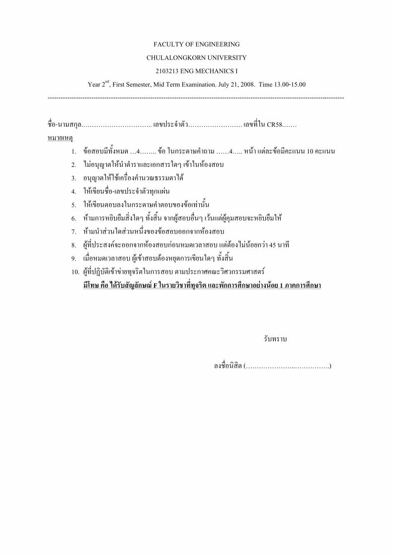
1. The uniform I-beam of mass m is supported at its ends on two fixed horizontal rails as shown. Determine the maximum horizontal force P which can be applied without causing the beam to slip, and find the corresponding value of the friction force at A. The coefficient of static friction between the beam and the rails is sμ . Also, take
2/ lb < .
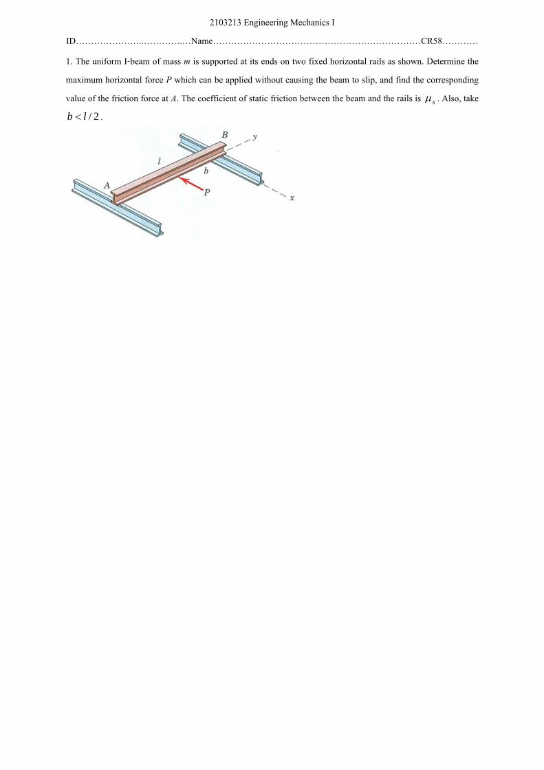
Figure 1: Free body diagram of problem 1
Solution: The approach to this problem is to determine the force P that wouldmake the ends A and B start to slip. The one which requires less magnitudewould be the answer.
Free body diagram of the beam is drawn in fig. 1. By the symmetrical supportof the I-beam, the normal force developed at each end would be the same andequal to half of the beam’s weight. FA and FB denote the corresponding frictionforces. If the beam is about to slip at end A,
FA = µsmg
2,
assuming support B has not yet reached the impending motion status. Take themoment about B along the z-axis,
[ΣMBz= 0] −Pb + µs
mg2
l = 0,
P = µsmgl2b
.
Instead, had the beam is to slip at end B first, the friction at B would be thestatic friction;
FB = µsmg
2.
Chulalongkorn University Phongsaen PITAKWATCHARA
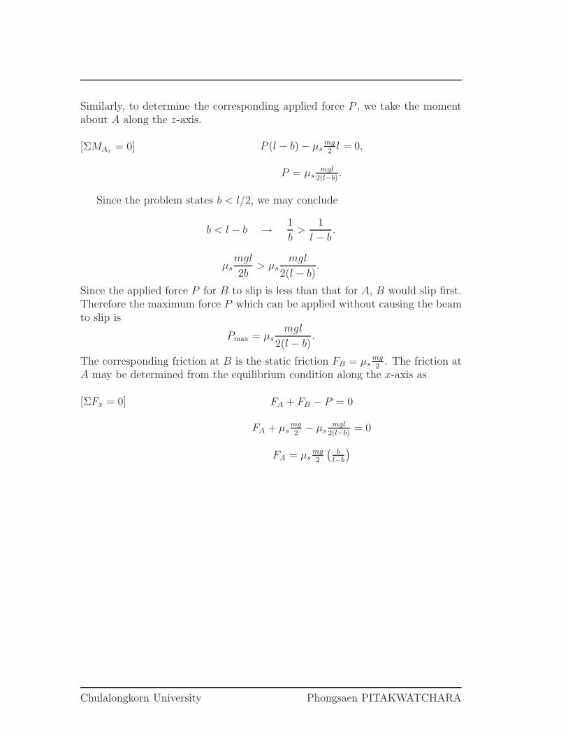
Similarly, to determine the corresponding applied force P , we take the momentabout A along the z-axis.
[ΣMAz= 0] P (l − b) − µs
mg2
l = 0,
P = µsmgl
2(l−b).
Since the problem states b < l/2, we may conclude
b < l − b → 1
b>
1
l − b.
µsmgl
2b> µs
mgl
2(l − b).
Since the applied force P for B to slip is less than that for A, B would slip first.Therefore the maximum force P which can be applied without causing the beamto slip is
Pmax = µsmgl
2(l − b).
The corresponding friction at B is the static friction FB = µsmg2
. The friction atA may be determined from the equilibrium condition along the x-axis as
[ΣFx = 0] FA + FB − P = 0
FA + µsmg2− µs
mgl2(l−b)
= 0
FA = µsmg2
(
bl−b
)
Chulalongkorn University Phongsaen PITAKWATCHARA
2103213 Engineering Mechanics I ID…………………..………….…Name……………………………………………………………CR58…………
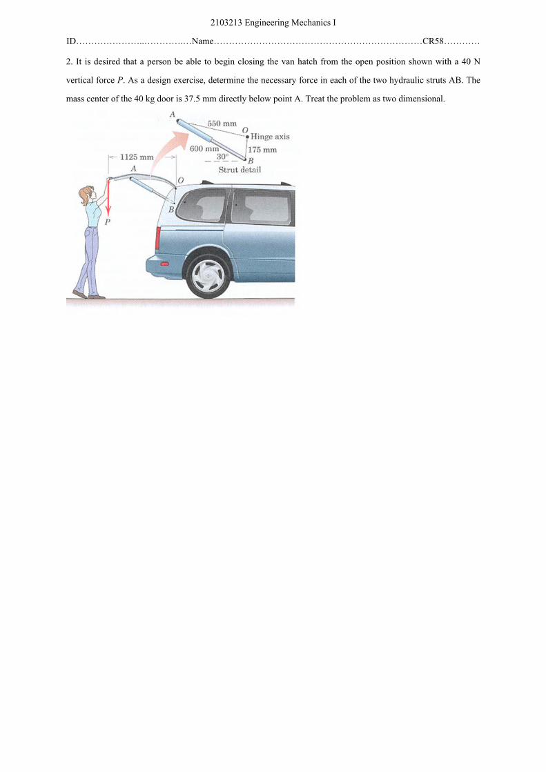
2. It is desired that a person be able to begin closing the van hatch from the open position shown with a 40 N vertical force P. As a design exercise, determine the necessary force in each of the two hydraulic struts AB. The mass center of the 40 kg door is 37.5 mm directly below point A. Treat the problem as two dimensional.
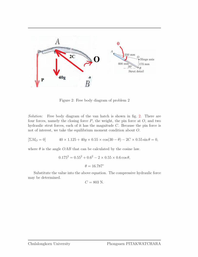
Figure 2: Free body diagram of problem 2
Solution: Free body diagram of the van hatch is shown in fig. 2. There arefour forces, namely the closing force P , the weight, the pin force at O, and twohydraulic strut forces, each of it has the magnitude C. Because the pin force isnot of interest, we take the equilibrium moment condition about O.
[ΣMO = 0] 40 × 1.125 + 40g × 0.55 × cos(30 − θ) − 2C × 0.55 sin θ = 0,
where θ is the angle OAB that can be calculated by the cosine law.
0.1752 = 0.552 + 0.62 − 2 × 0.55 × 0.6 cos θ,
θ = 16.787◦
Substitute the value into the above equation. The compressive hydraulic forcemay be determined.
C = 803 N.
Chulalongkorn University Phongsaen PITAKWATCHARA
2103213 Engineering Mechanics I ID…………………..………….…Name……………………………………………………………CR58…………
3. One of the vertical walls supporting end B of the 200 kg uniform shaft is turned through a o30 angle as shown here. End A is still supported by the ball and socket connection in the horizontal x-y plane. Calculate the magnitudes of the forces P and R exerted on the ball end B of the shaft by the vertical walls C and D, respectively.
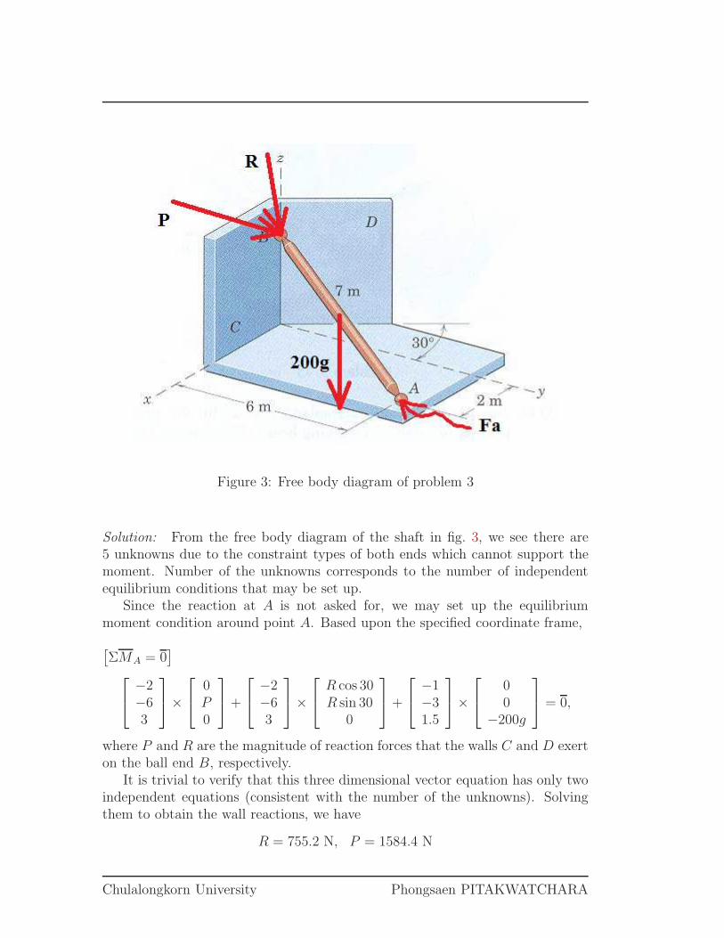
Figure 3: Free body diagram of problem 3
Solution: From the free body diagram of the shaft in fig. 3, we see there are5 unknowns due to the constraint types of both ends which cannot support themoment. Number of the unknowns corresponds to the number of independentequilibrium conditions that may be set up.
Since the reaction at A is not asked for, we may set up the equilibriummoment condition around point A. Based upon the specified coordinate frame,
[
ΣMA = 0]
−2−63
×
0P0
+
−2−63
×
R cos 30R sin 30
0
+
−1−31.5
×
00
−200g
= 0,
where P and R are the magnitude of reaction forces that the walls C and D exerton the ball end B, respectively.
It is trivial to verify that this three dimensional vector equation has only twoindependent equations (consistent with the number of the unknowns). Solvingthem to obtain the wall reactions, we have
R = 755.2 N, P = 1584.4 N
Chulalongkorn University Phongsaen PITAKWATCHARA
2103213 Engineering Mechanics I ID…………………..………….…Name……………………………………………………………CR58…………
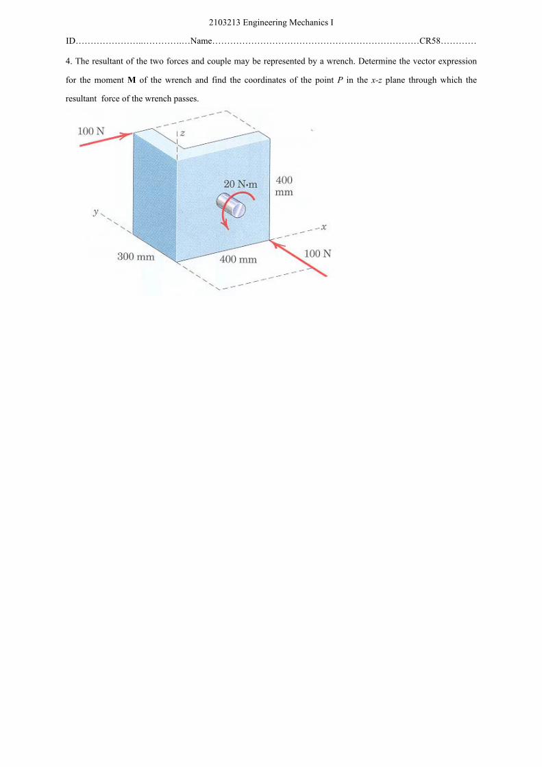
4. The resultant of the two forces and couple may be represented by a wrench. Determine the vector expression for the moment M of the wrench and find the coordinates of the point P in the x-z plane through which the resultant force of the wrench passes.
Solution 1: First, choose the origin O and determine the equivalent force-coupleresultant. Hence,
R = 100i + 100j N
MO = 0.4 × 100k − 0.3 × 100k + 0.4 × 100j− 20j = 20j + 10k Nm
Next, project the couple MO onto the direction parallel and perpendicular tonR, for which its value is
nR =R
|R| =1√2i +
1√2j
Consequently, the components of MO are
M‖ = (MO · nR)nR = 10i + 10j Nm
M⊥ = MO −M‖ = −10i + 10j + 10k Nm
Thirdly, transform the couple M⊥ into pair of forces R and −R. −R is atthe origin O. R is along the line through which it passes the point P in the x-zplane. Let r be the position vector of that point P .
r = xi + zk m
Consistency in the transformation requires the induced moment of R aboutO be equal to the couple M⊥:
M⊥ = r ×R
−10i + 10j + 10k = (xi + zk) × (100i + 100j)
Solving the above vector equation yields the coordinate values:
x = 0.1 m z = 0.1 m
To conclude, the equivalent wrench system consists of the couple M‖,
M‖ = 10i + 10j Nm
and the force R,R = 100i + 100j N
of which its line of action passes through the point P ,
x = 0.1 m z = 0.1 m
in the x-z plane.
Chulalongkorn University Phongsaen PITAKWATCHARA
Solution 2: The resultant force is just simply
R = 100i + 100j N
Another way to determine the wrench is to assume the point where the wrenchpasses. Let point P in the x-z plane, where the wrench passes, has the coordinate(x, 0, z). Consequently, the moment of the force system about P is
MP = 100 × zi + 100 × (0.4 − x)k + 100 × (0.4 − z) j− 100 × 0.3k − 20j= 100zi + (20 − 100z) j + (10 − 100x)k Nm
Note that this moment at P must be equal to the couple of the wrench passingthrough P , which is parallel to the resultant force. That is, MP ‖ R. Theconstraint eqautions are obtained by comparing the ratio of their components:
100
100z=
100
20 − 100z
and10 − 100x = 0
As the result,x = 0.1 m, z = 0.1 m
and substituting back into the moment equation, we have
MP = 10i + 10j Nm
Chulalongkorn University Phongsaen PITAKWATCHARA

FACULTY OF ENGINEERING CHULALONGKORN UNIVERSITY
2103213 ENG MECHANICS I Year 2nd, First Semester, Final Examination. September 22, 2008. Time 13.00-15.00
---------------------------------------------------------------------------------------------------------------------------------------- ชอ-นามสกล.………………………….. เลขประจาตว……………………. เลขทใน CR58.…… หมายเหต
1. ขอสอบมทงหมด …5….. ขอ ในกระดาษคาถาม ……5….. หนา แตละขอมคะแนน 10 คะแนน 2. ไมอนญาตใหนาตาราและเอกสารใดๆ เขาในหองสอบ 3. อนญาตใหใชเครองคานวณธรรมดาได 4. ใหเขยนชอ-เลขประจาตวทกแผน 5. ใหเขยนตอบลงในกระดาษคาตอบของขอเทานน 6. หามการหยบยมสงใดๆ ทงสน จากผสอบอนๆ เวนแตผคมสอบจะหยบยมให 7. หามนาสวนใดสวนหนงของขอสอบออกจากหองสอบ 8. ผทประสงคจะออกจากหองสอบกอนหมดเวลาสอบ แตตองไมนอยกวา 45 นาท 9. เมอหมดเวลาสอบ ผเขาสอบตองหยดการเขยนใดๆ ทงสน 10. ผทปฏบตเขาขายทจรตในการสอบ ตามประกาศคณะวศวกรรมศาสตร
มโทษ คอ ไดรบสญลกษณ F ในรายวชาททจรต และพกการศกษาอยางนอย 1 ภาคการศกษา รบทราบ ลงชอนสต (…………………..…………….)
2103213 Engineering Mechanics I ID…………………..………….…Name……………………………………………………………CR58…………
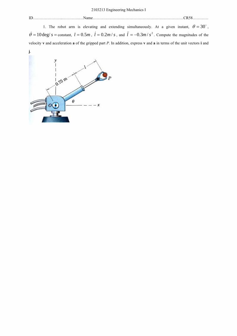
1. The robot arm is elevating and extending simultaneously. At a given instant, o30=θ , == sdeg/10θ& constant, ml 5.0= , sml /2.0=& , and 2/3.0 sml −=&& . Compute the magnitudes of the
velocity v and acceleration a of the gripped part P. In addition, express v and a in terms of the unit vectors i and j.
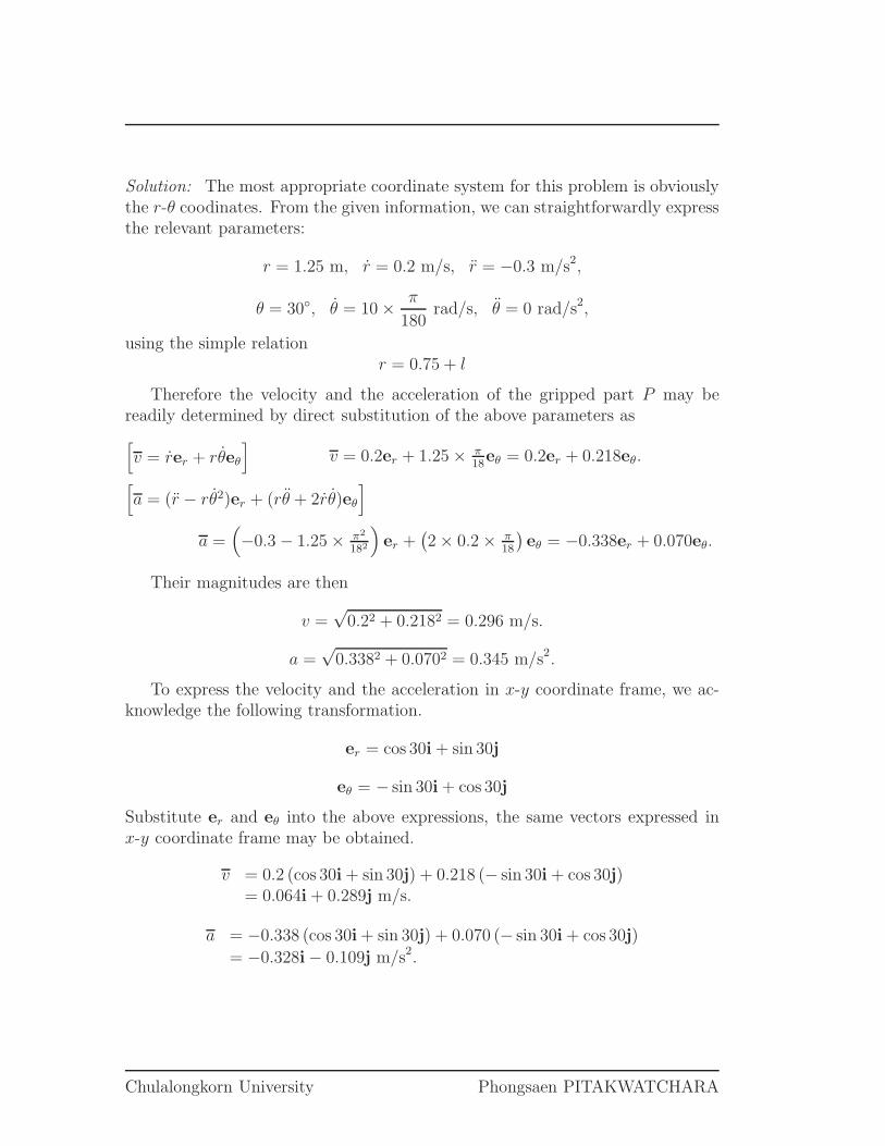
Solution: The most appropriate coordinate system for this problem is obviouslythe r-θ coodinates. From the given information, we can straightforwardly expressthe relevant parameters:
r = 1.25 m, r = 0.2 m/s, r = −0.3 m/s2,
θ = 30◦, θ = 10 × π
180rad/s, θ = 0 rad/s2,
using the simple relationr = 0.75 + l
Therefore the velocity and the acceleration of the gripped part P may bereadily determined by direct substitution of the above parameters as
[
v = rer + rθeθ
]
v = 0.2er + 1.25 × π18
eθ = 0.2er + 0.218eθ.
[
a = (r − rθ2)er + (rθ + 2rθ)eθ
]
a =(
−0.3 − 1.25 × π2
182
)
er +(
2 × 0.2 × π18
)
eθ = −0.338er + 0.070eθ.
Their magnitudes are then
v =√
0.22 + 0.2182 = 0.296 m/s.
a =√
0.3382 + 0.0702 = 0.345 m/s2.
To express the velocity and the acceleration in x-y coordinate frame, we ac-knowledge the following transformation.
er = cos 30i + sin 30j
eθ = − sin 30i + cos 30j
Substitute er and eθ into the above expressions, the same vectors expressed inx-y coordinate frame may be obtained.
v = 0.2 (cos 30i + sin 30j) + 0.218 (− sin 30i + cos 30j)= 0.064i + 0.289j m/s.
a = −0.338 (cos 30i + sin 30j) + 0.070 (− sin 30i + cos 30j)
= −0.328i − 0.109j m/s2.
Chulalongkorn University Phongsaen PITAKWATCHARA
2103213 Engineering Mechanics I ID…………………..………….…Name……………………………………………………………CR58…………
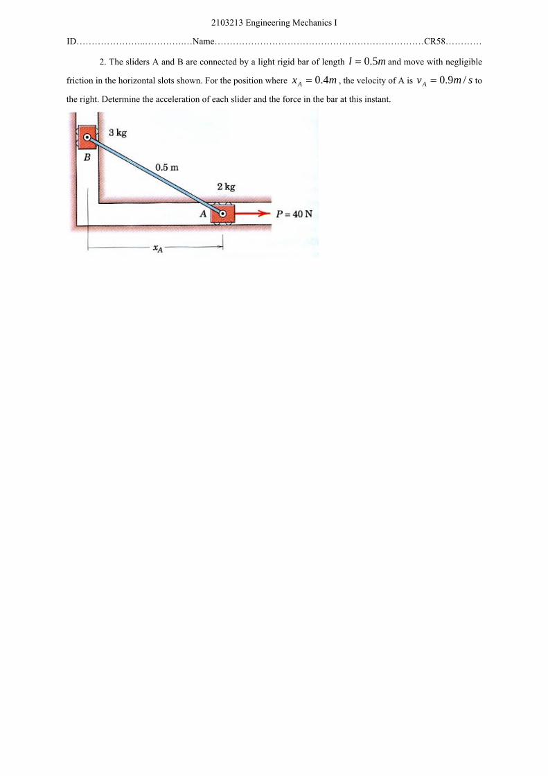
2. The sliders A and B are connected by a light rigid bar of length ml 5.0= and move with negligible friction in the horizontal slots shown. For the position where mxA 4.0= , the velocity of A is smvA /9.0= to the right. Determine the acceleration of each slider and the force in the bar at this instant.
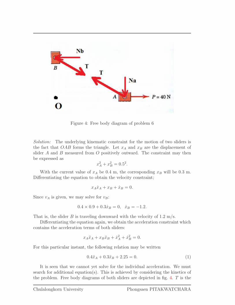
Figure 4: Free body diagram of problem 6
Solution: The underlying kinematic constraint for the motion of two sliders isthe fact that OAB forms the triangle. Let xA and xB are the displacement ofslider A and B measured from O positively outward. The constraint may thenbe expressed as
x2A + x2
B = 0.52.
With the current value of xA be 0.4 m, the corresponding xB will be 0.3 m.Differentiating the equation to obtain the velocity constraint;
xAxA + xB + xB = 0.
Since vA is given, we may solve for vB:
0.4 × 0.9 + 0.3xB = 0, xB = −1.2.
That is, the slider B is traveling downward with the velocity of 1.2 m/s.Differentiating the equation again, we obtain the acceleration constraint which
contains the acceleration terms of both sliders:
xAxA + xB xB + x2A + x2
B = 0.
For this particular instant, the following relation may be written
0.4xA + 0.3xB + 2.25 = 0. (1)
It is seen that we cannot yet solve for the individual acceleration. We mustsearch for additional equation(s). This is achieved by considering the kinetics ofthe problem. Free body diagrams of both sliders are depicted in fig. 4. T is the
Chulalongkorn University Phongsaen PITAKWATCHARA
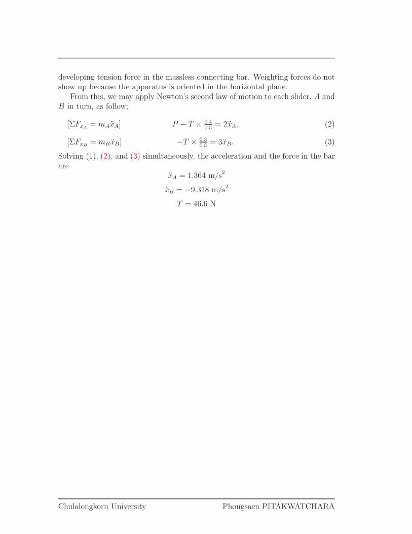
developing tension force in the massless connecting bar. Weighting forces do notshow up because the apparatus is oriented in the horizontal plane.
From this, we may apply Newton’s second law of motion to each slider, A andB in turn, as follow;
[ΣFxA= mAxA] P − T × 0.4
0.5= 2xA. (2)
[ΣFxB= mBxB] −T × 0.3
0.5= 3xB. (3)
Solving (1), (2), and (3) simultaneously, the acceleration and the force in the barare
xA = 1.364 m/s2
xB = −9.318 m/s2
T = 46.6 N
Chulalongkorn University Phongsaen PITAKWATCHARA
2103213 Engineering Mechanics I ID…………………..………….…Name……………………………………………………………CR58…………
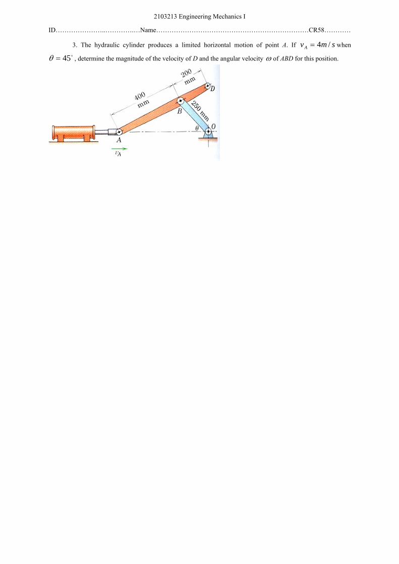
3. The hydraulic cylinder produces a limited horizontal motion of point A. If smvA /4= when o45=θ , determine the magnitude of the velocity of D and the angular velocity ω of ABD for this position.
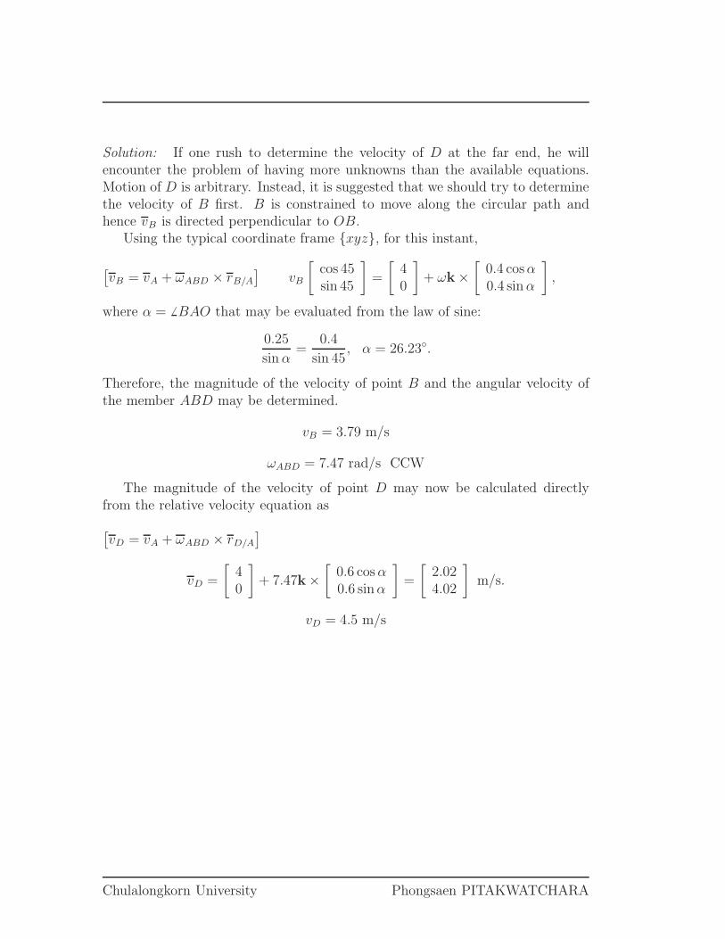
Solution: If one rush to determine the velocity of D at the far end, he willencounter the problem of having more unknowns than the available equations.Motion of D is arbitrary. Instead, it is suggested that we should try to determinethe velocity of B first. B is constrained to move along the circular path andhence vB is directed perpendicular to OB.
Using the typical coordinate frame {xyz}, for this instant,
[
vB = vA + ωABD × rB/A
]
vB
[
cos 45sin 45
]
=
[
40
]
+ ωk ×[
0.4 cosα0.4 sin α
]
,
where α = 6 BAO that may be evaluated from the law of sine:
0.25
sin α=
0.4
sin 45, α = 26.23◦.
Therefore, the magnitude of the velocity of point B and the angular velocity ofthe member ABD may be determined.
vB = 3.79 m/s
ωABD = 7.47 rad/s CCW
The magnitude of the velocity of point D may now be calculated directlyfrom the relative velocity equation as
[
vD = vA + ωABD × rD/A
]
vD =
[
40
]
+ 7.47k ×[
0.6 cos α0.6 sinα
]
=
[
2.024.02
]
m/s.
vD = 4.5 m/s
Chulalongkorn University Phongsaen PITAKWATCHARA
2103213 Engineering Mechanics I ID…………………..………….…Name……………………………………………………………CR58…………
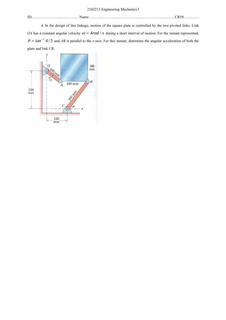
4. In the design of this linkage, motion of the square plate is controlled by the two pivoted links. Link OA has a constant angular velocity srad /4=ω during a short interval of motion. For the instant represented,
3/4tan 1−=θ and AB is parallel to the x-axis. For this instant, determine the angular acceleration of both the plate and link CB.
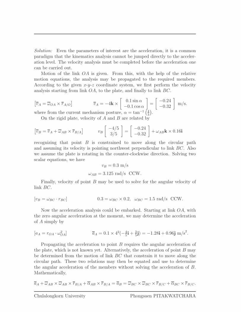
Solution: Even the parameters of interest are the acceleration, it is a commonparadigm that the kinematics analysis cannot be jumped directly to the acceler-ation level. The velocity analysis must be completed before the acceleration onecan be carried out.
Motion of the link OA is given. From this, with the help of the relativemotion equations, the analysis may be propagated to the required members.According to the given x-y-z coordinate system, we first perform the velocityanalysis starting from link OA, to the plate, and finally to link BC.
[
vA = ωOA × rA/O
]
vA = −4k ×[
0.1 sin α−0.1 cos α
]
=
[
−0.24−0.32
]
m/s.
where from the current mechanism posture, α = tan−1(
43
)
.On the rigid plate, velocity of A and B are related by
[
vB = vA + ωAB × rB/A
]
vB
[
−4/53/5
]
=
[
−0.24−0.32
]
+ ωABk × 0.16i
recognizing that point B is constrained to move along the circular pathand assuming its velocity is pointing northwest perpendicular to link BC. Alsowe assume the plate is rotating in the counter-clockwise direction. Solving twoscalar equations, we have
vB = 0.3 m/s
ωAB = 3.125 rad/s CCW.
Finally, velocity of point B may be used to solve for the angular velocity oflink BC.
[vB = ωBC · rBC ] 0.3 = ωBC × 0.2, ωBC = 1.5 rad/s CCW.
Now the acceleration analysis could be embarked. Starting at link OA, withthe zero angular acceleration at the moment, we may determine the accelerationof A simply by
[aA = rOA · ω2OA] aA = 0.1 × 42(−4
5i + 3
5j) = −1.28i + 0.96j m/s2.
Propagating the acceleration to point B requires the angular acceleration ofthe plate, which is not known yet. Alternatively, the acceleration of point B maybe determined from the motion of link BC that constrain it to move along thecircular path. These two relations may then be equated and use to determinethe angular acceleration of the members without solving the acceleration of B.Mathematically,
aA + ωAB × ωAB × rB/A + αAB × rB/A = aB = ωBC × ωBC × rB/C + αBC × rB/C .
Chulalongkorn University Phongsaen PITAKWATCHARA
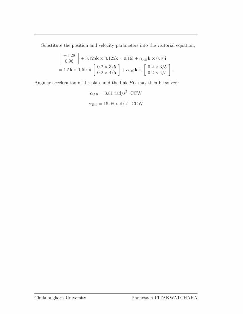
Substitute the position and velocity parameters into the vectorial equation,
[
−1.280.96
]
+ 3.125k× 3.125k× 0.16i + αABk × 0.16i
= 1.5k × 1.5k ×[
0.2 × 3/50.2 × 4/5
]
+ αBCk ×[
0.2 × 3/50.2 × 4/5
]
.
Angular acceleration of the plate and the link BC may then be solved:
αAB = 3.81 rad/s2 CCW
αBC = 16.08 rad/s2 CCW
Chulalongkorn University Phongsaen PITAKWATCHARA
2103213 Engineering Mechanics I ID…………………..………….…Name……………………………………………………………CR58…………
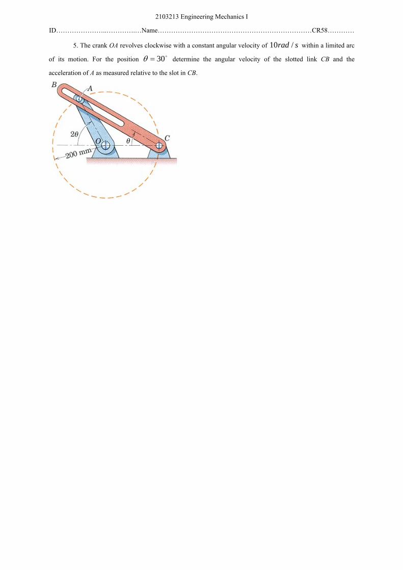
5. The crank OA revolves clockwise with a constant angular velocity of srad /10 within a limited arc of its motion. For the position o30=θ determine the angular velocity of the slotted link CB and the acceleration of A as measured relative to the slot in CB.
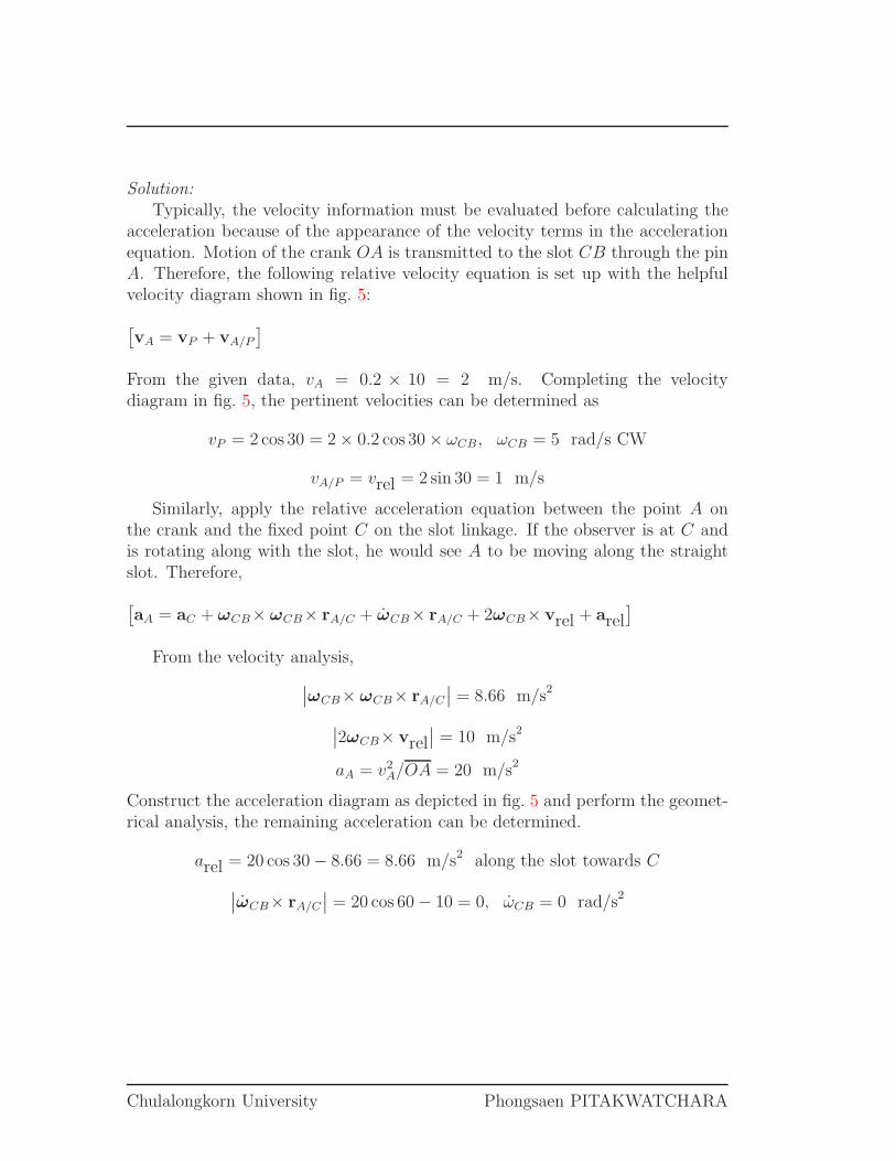
Solution:
Typically, the velocity information must be evaluated before calculating theacceleration because of the appearance of the velocity terms in the accelerationequation. Motion of the crank OA is transmitted to the slot CB through the pinA. Therefore, the following relative velocity equation is set up with the helpfulvelocity diagram shown in fig. 5:
[
vA = vP + vA/P
]
From the given data, vA = 0.2 × 10 = 2 m/s. Completing the velocitydiagram in fig. 5, the pertinent velocities can be determined as
vP = 2 cos 30 = 2 × 0.2 cos 30 × ωCB, ωCB = 5 rad/s CW
vA/P = vrel = 2 sin 30 = 1 m/s
Similarly, apply the relative acceleration equation between the point A onthe crank and the fixed point C on the slot linkage. If the observer is at C andis rotating along with the slot, he would see A to be moving along the straightslot. Therefore,
[
aA = aC + ωCB× ωCB× rA/C + ωCB× rA/C + 2ωCB× vrel + arel]
From the velocity analysis,
∣
∣
ωCB× ωCB× rA/C
∣
∣ = 8.66 m/s2
∣
∣2ωCB× vrel∣
∣ = 10 m/s2
aA = v2A/OA = 20 m/s2
Construct the acceleration diagram as depicted in fig. 5 and perform the geomet-rical analysis, the remaining acceleration can be determined.
arel = 20 cos 30 − 8.66 = 8.66 m/s2 along the slot towards C
∣
∣
ωCB× rA/C
∣
∣ = 20 cos 60 − 10 = 0, ωCB = 0 rad/s2
Chulalongkorn University Phongsaen PITAKWATCHARA
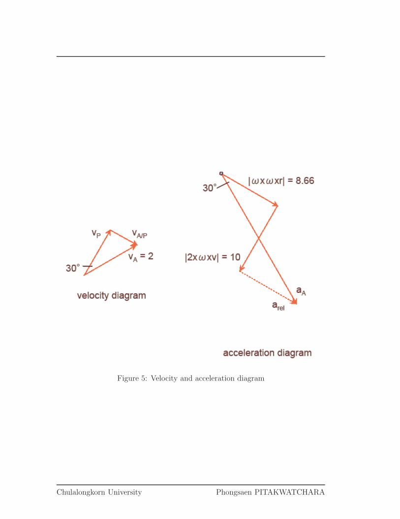
Figure 5: Velocity and acceleration diagram
Chulalongkorn University Phongsaen PITAKWATCHARA