Embed Size (px)
Citation preview

8/3/2019 Fluid Mechanics Benno 7
http://slidepdf.com/reader/full/fluid-mechanics-benno-7 1/25
TL2101
Mekanika Fluida I
Benno Rahardyan
Pertemuan 7
8/3/2019 Fluid Mechanics Benno 7
http://slidepdf.com/reader/full/fluid-mechanics-benno-7 2/25
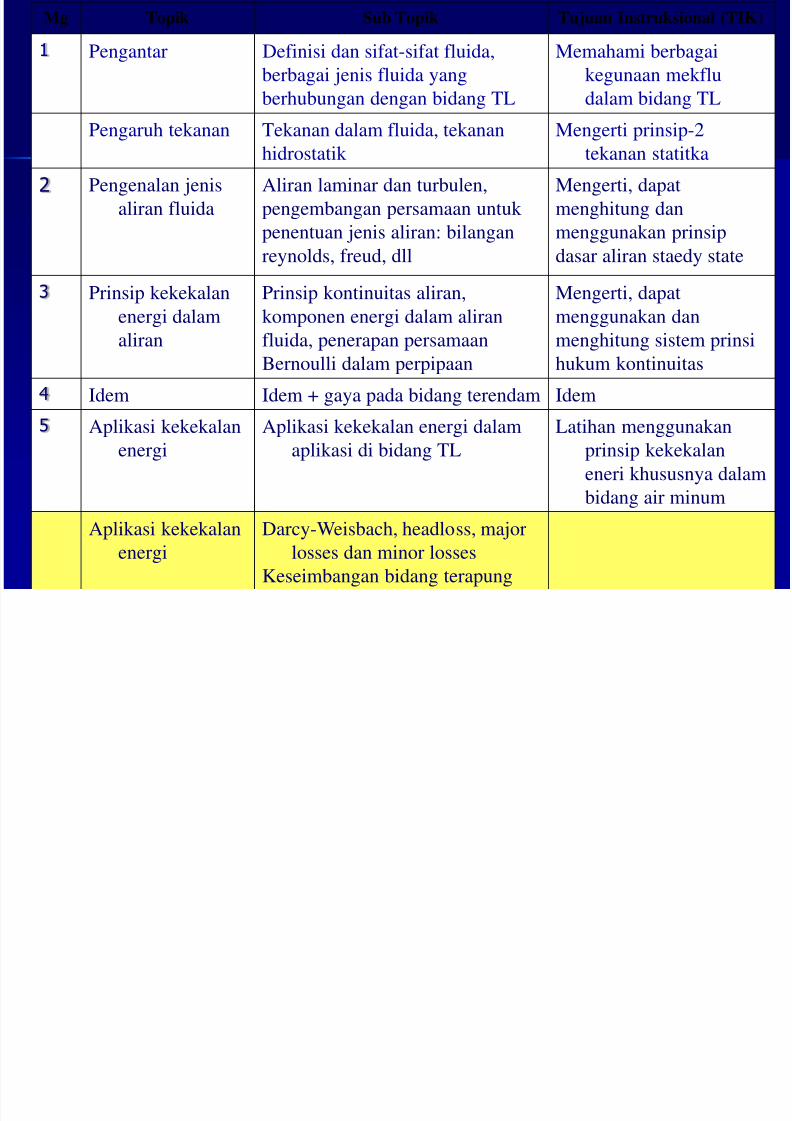
Mg Topik Sub Topik Tujuan Instruksional (TIK)
1 Pengantar Definisi dan sifat-sifat fluida,
berbagai jenis fluida yang
berhubungan dengan bidang TL
Memahami berbagai
kegunaan mekflu
dalam bidang TL
Pengaruh tekanan Tekanan dalam fluida, tekananhidrostatik Mengerti prinsip-2tekanan statitka
2 Pengenalan jenis
aliran fluida Aliran laminar dan turbulen,
pengembangan persamaan untuk
penentuan jenis aliran: bilangan
reynolds, freud, dll
Mengerti, dapat
menghitung dan
menggunakan prinsip
dasar aliran staedy state
3 Prinsip kekekalan
energi dalam
aliran
Prinsip kontinuitas aliran,
komponen energi dalam aliran
fluida, penerapan persamaan
Bernoulli dalam perpipaan
Mengerti, dapat
menggunakan dan
menghitung sistem prinsi
hukum kontinuitas
4 Idem Idem + gaya pada bidang terendam Idem
5 Aplikasi kekekalan
energi Aplikasi kekekalan energi dalam
aplikasi di bidang TL Latihan menggunakan
prinsip kekekalan
eneri khususnya dalam
bidang air minum
Aplikasi kekekalan
energi
Darcy-Weisbach, headloss, major
losses dan minor lossesKeseimbangan bidang terapung
8/3/2019 Fluid Mechanics Benno 7
http://slidepdf.com/reader/full/fluid-mechanics-benno-7 3/25
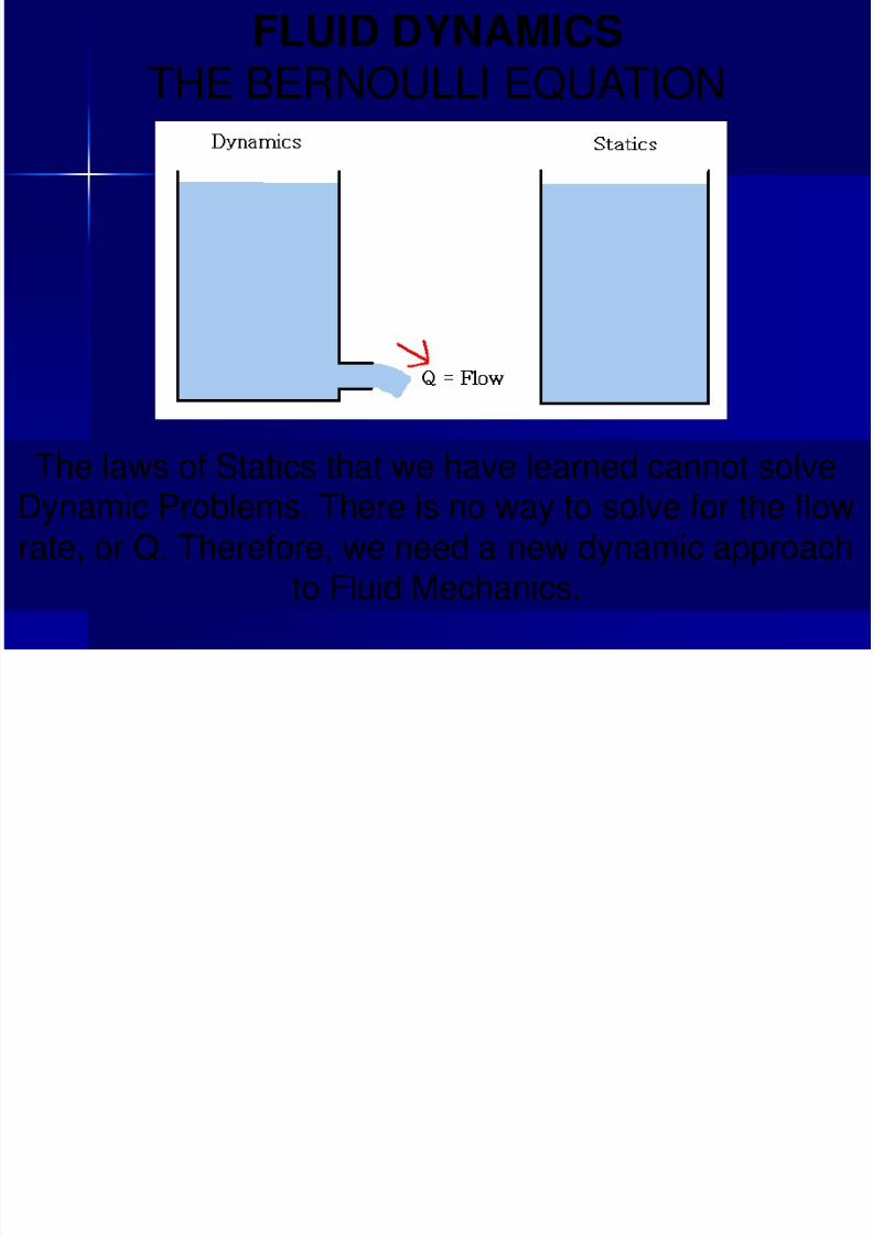
FLUID DYNAMICS
THE BERNOULLI EQUATION
The laws of Statics that we have learned cannot solveDynamic Problems. There is no way to solve for the flowrate, or Q. Therefore, we need a new dynamic approach
to Fluid Mechanics.
8/3/2019 Fluid Mechanics Benno 7
http://slidepdf.com/reader/full/fluid-mechanics-benno-7 4/25
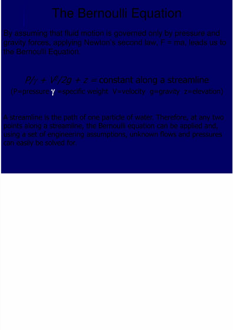
The Bernoulli Equation
By assuming that fluid motion is governed only by pressure and
gravity forces, applying Newton’s second law, F = ma, leads us tothe Bernoulli Equation.
P/ g + V 2 /2g + z = constant along a streamline (P=pressure g =specific weight V=velocity g=gravity z=elevation)
A streamline is the path of one particle of water. Therefore, at any twopoints along a streamline, the Bernoulli equation can be applied and,using a set of engineering assumptions, unknown flows and pressurescan easily be solved for.
8/3/2019 Fluid Mechanics Benno 7
http://slidepdf.com/reader/full/fluid-mechanics-benno-7 5/25
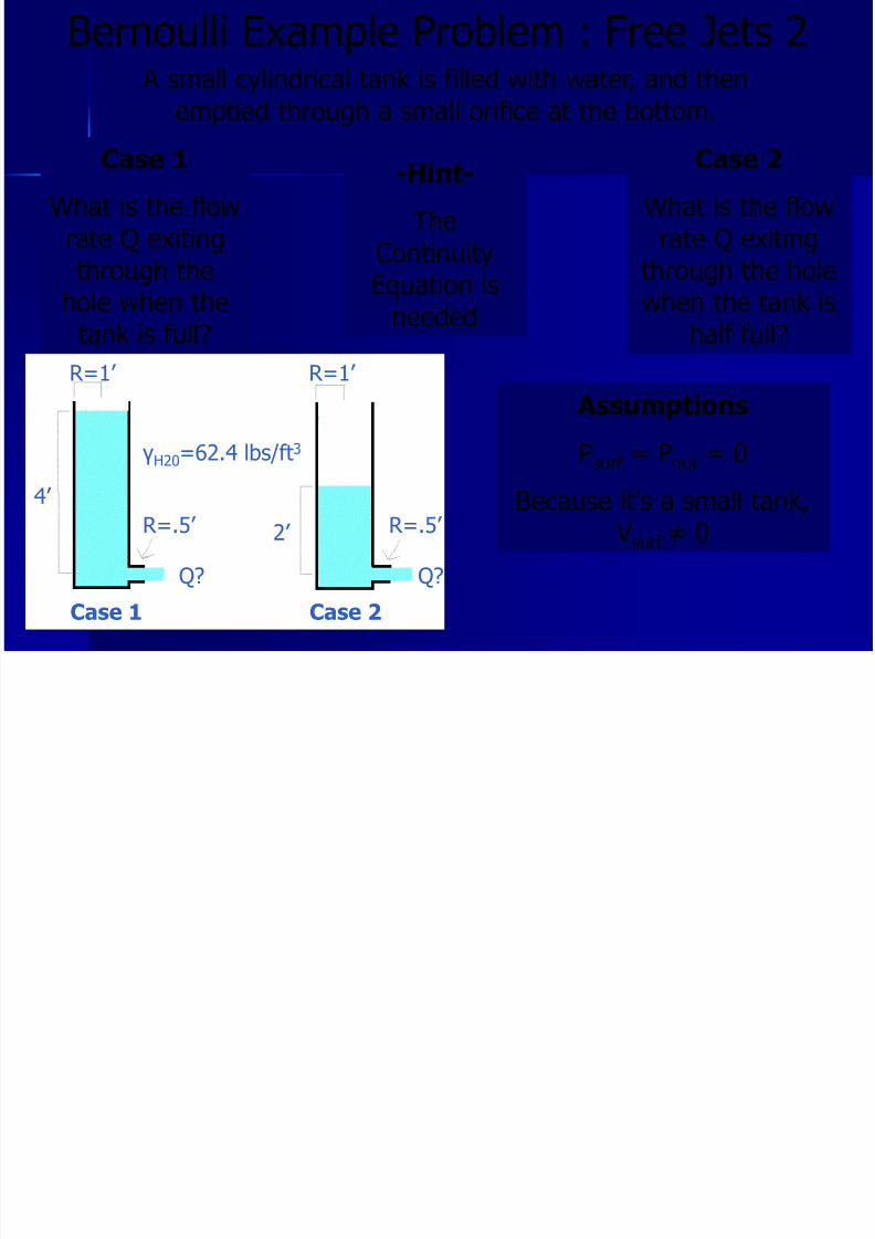
Bernoulli Example Problem : Free Jets 2
R=1’ R=1’
4’
R=.5’ R=.5’ 2’
γH20=62.4 lbs/ft3
Q? Q?
Case 1 Case 2
A small cylindrical tank is filled with water, and thenemptied through a small orifice at the bottom.
Case 1
What is the flowrate Q exitingthrough the
hole when thetank is full?
Case 2
What is the flowrate Q exiting
through the hole
when the tank ishalf full?
-Hint-
TheContinuityEquation is
needed
Assumptions
Psurf = Pout = 0Because it’s a small tank,
Vsurf ≠ 0
8/3/2019 Fluid Mechanics Benno 7
http://slidepdf.com/reader/full/fluid-mechanics-benno-7 6/25
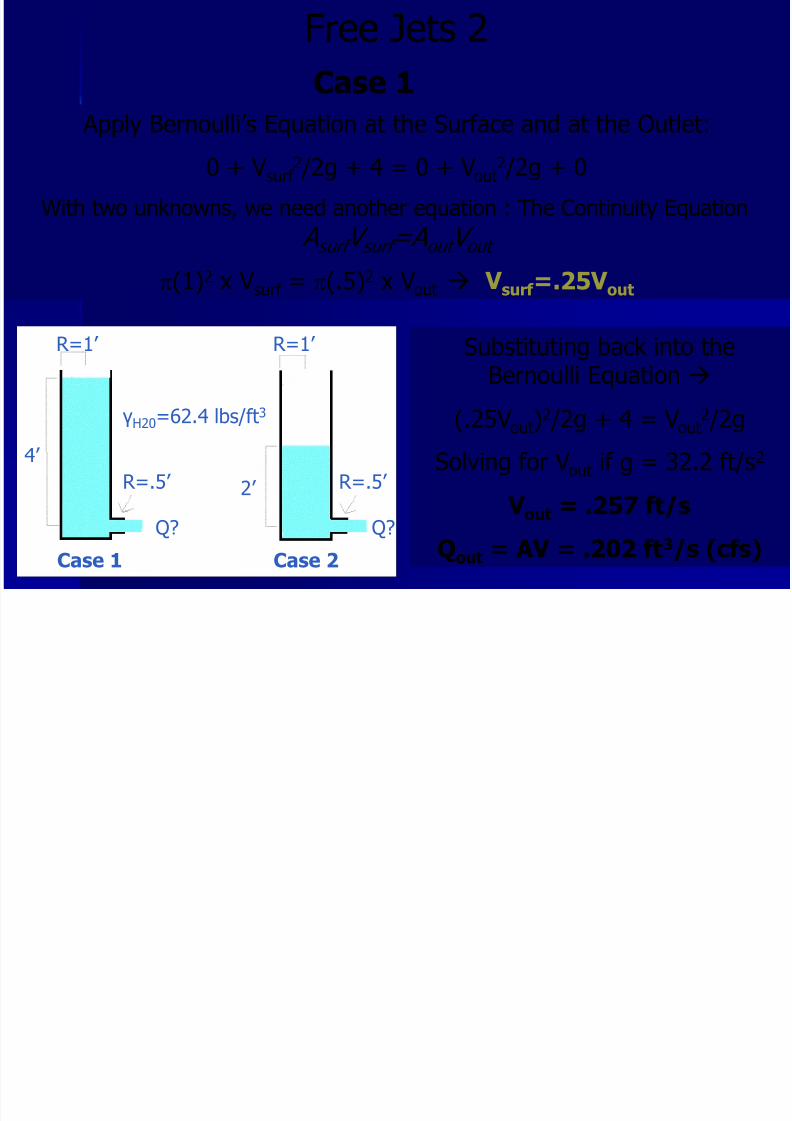
Free Jets 2
R=1’ R=1’
4’
R=.5’ R=.5’ 2’
γH20=62.4 lbs/ft3
Q? Q?
Case 1 Case 2
Case 1
Apply Bernoulli’s Equation at the Surface and at the Outlet:
0 + Vsurf 2 /2g + 4 = 0 + Vout
2 /2g + 0
With two unknowns, we need another equation : The Continuity Equation
A surf V surf =A out V out
p(1)2 x Vsurf = p(.5)2 x Vout V surf =.25V out
Substituting back into theBernoulli Equation
(.25Vout)2 /2g + 4 = Vout2 /2g
Solving for Vout if g = 32.2 ft/s2
V out = .257 ft/s
Qout = AV = .202 ft3/s (cfs)
8/3/2019 Fluid Mechanics Benno 7
http://slidepdf.com/reader/full/fluid-mechanics-benno-7 7/25
Bernoulli Example Problem : Free Jets 2
R=1’ R=1’
4’
R=.5’ R=.5’ 2’
γH20=62.4 lbs/ft3
Q? Q?
Case 1 Case 2
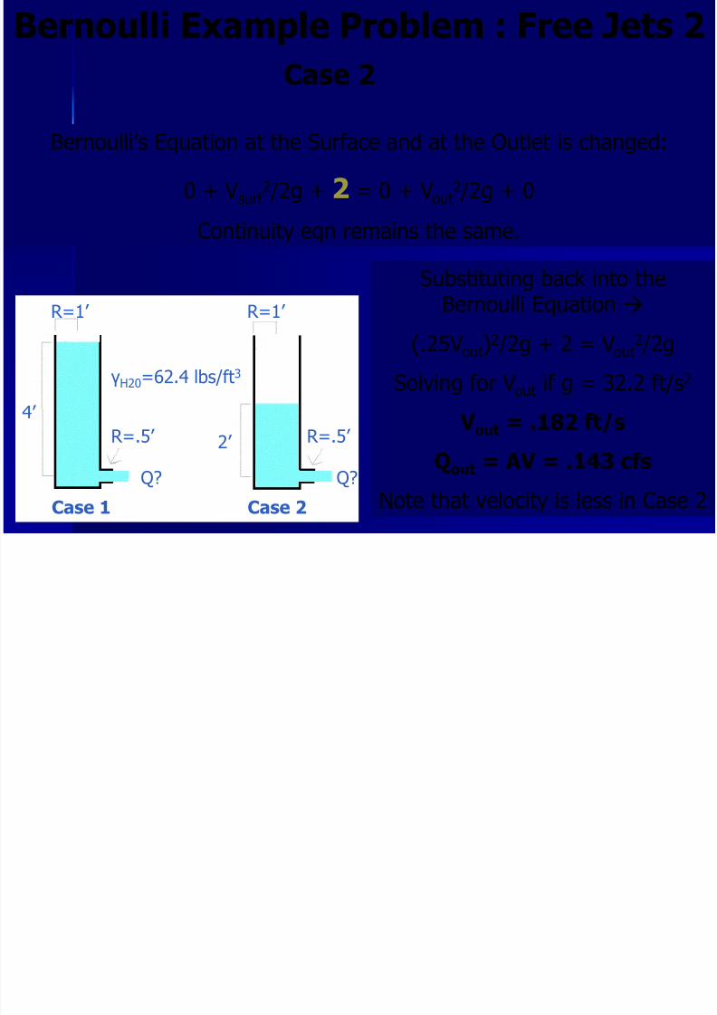
Case 2
Bernoulli’s Equation at the Surface and at the Outlet is changed:
0 + Vsurf 2 /2g + 2 = 0 + Vout
2 /2g + 0
Continuity eqn remains the same.
Substituting back into theBernoulli Equation
(.25Vout)2 /2g + 2 = Vout
2 /2g
Solving for Vout if g = 32.2 ft/s2
V out = .182 ft/s
Qout = AV = .143 cfs
Note that velocity is less in Case 2
8/3/2019 Fluid Mechanics Benno 7
http://slidepdf.com/reader/full/fluid-mechanics-benno-7 8/25
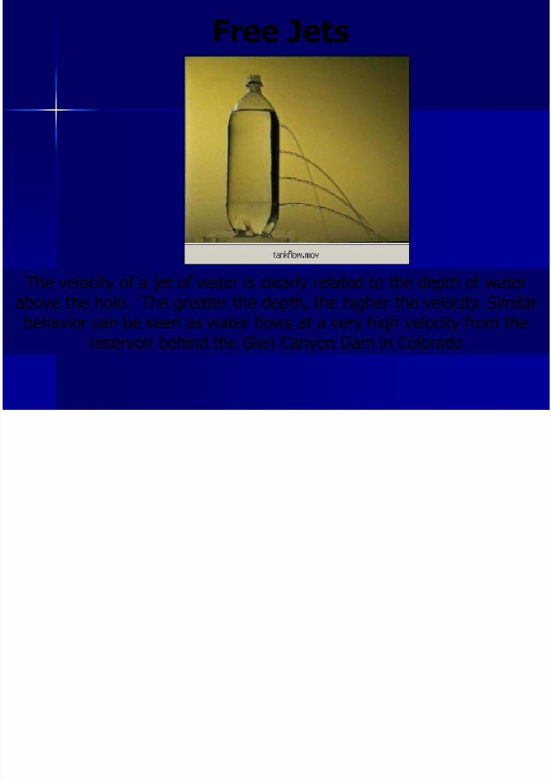
Free Jets
The velocity of a jet of water is clearly related to the depth of waterabove the hole. The greater the depth, the higher the velocity. Similarbehavior can be seen as water flows at a very high velocity from the
reservoir behind the Glen Canyon Dam in Colorado
8/3/2019 Fluid Mechanics Benno 7
http://slidepdf.com/reader/full/fluid-mechanics-benno-7 9/25
The Energy Line and the Hydraulic Grade Line
Looking at the Bernoulli equation again:
P/γ + V2 /2g + z = constant on a streamlineThis constant is called the total head (energy), H
Because energy is assumed to be conserved, at any point alongthe streamline, the total head is always constant
Each term in the Bernoulli equation is a type of head.
P/γ = Pressure Head
V2 /2g = Velocity Head
Z = elevation head
These three heads, summed together, will always equal H
Next we will look at this graphically…
8/3/2019 Fluid Mechanics Benno 7
http://slidepdf.com/reader/full/fluid-mechanics-benno-7 10/25
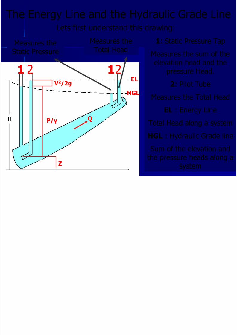
The Energy Line and the Hydraulic Grade LineLets first understand this drawing:
Q
Measures theStatic Pressure
Measures theTotal Head
1 2
Z
P/γ
V 2/2gEL
HGL
12
1: Static Pressure Tap
Measures the sum of theelevation head and the
pressure Head.
2: Pilot Tube
Measures the Total Head
EL : Energy Line
Total Head along a systemHGL : Hydraulic Grade line
Sum of the elevation andthe pressure heads along a
system
8/3/2019 Fluid Mechanics Benno 7
http://slidepdf.com/reader/full/fluid-mechanics-benno-7 11/25
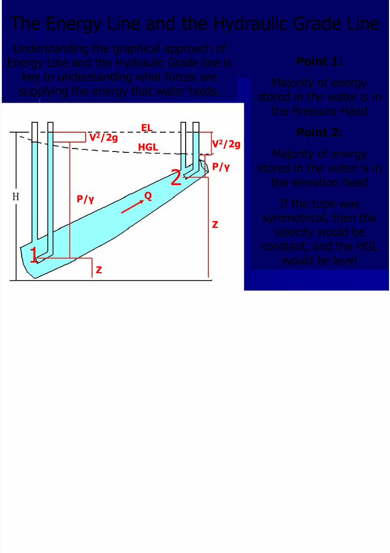
The Energy Line and the Hydraulic Grade Line
Q
Z
P/γ
V 2/2g
EL
HGL
Understanding the graphical approach of
Energy Line and the Hydraulic Grade line iskey to understanding what forces aresupplying the energy that water holds.
V 2/2g
P/γ
Z
1
2
Point 1:
Majority of energystored in the water is in
the Pressure Head
Point 2:Majority of energy
stored in the water is inthe elevation head
If the tube wassymmetrical, then the
velocity would beconstant, and the HGL
would be level
8/3/2019 Fluid Mechanics Benno 7
http://slidepdf.com/reader/full/fluid-mechanics-benno-7 12/25
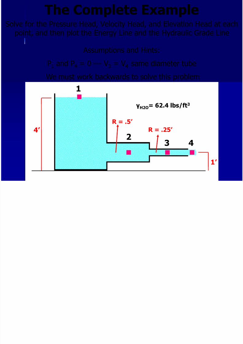
The Complete ExampleSolve for the Pressure Head, Velocity Head, and Elevation Head at each
point, and then plot the Energy Line and the Hydraulic Grade Line
1
23 4
1’
4’
γH2O= 62.4 lbs/ft3
Assumptions and Hints:
P1 and P4 = 0 --- V3 = V4 same diameter tube
We must work backwards to solve this problem
R = .5’
R = .25’
8/3/2019 Fluid Mechanics Benno 7
http://slidepdf.com/reader/full/fluid-mechanics-benno-7 13/25
1
23 4
1’
4’
γH2O= 62.4 lbs/ft3
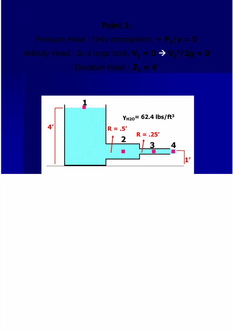
Point 1:
Pressure Head : Only atmospheric P1/γ = 0 Velocity Head : In a large tank, V 1 = 0 V 1
2/2g = 0
Elevation Head : Z1 = 4’
R = .5’ R = .25’
8/3/2019 Fluid Mechanics Benno 7
http://slidepdf.com/reader/full/fluid-mechanics-benno-7 14/25
1
23 4
1’
4’
γH2O= 62.4 lbs/ft3
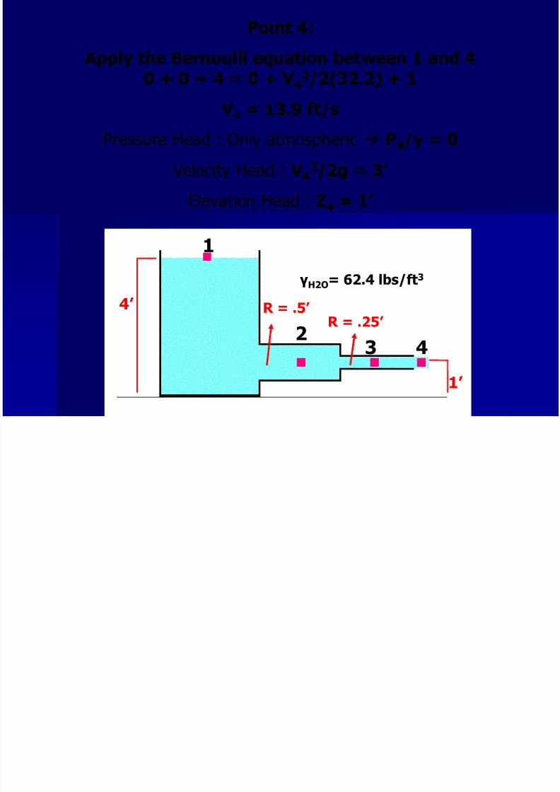
Point 4:
Apply the Bernoulli equation between 1 and 40 + 0 + 4 = 0 + V 4
2/2(32.2) + 1
V 4 = 13.9 ft/s
Pressure Head : Only atmospheric P4/γ = 0
Velocity Head : V 42/2g = 3’
Elevation Head : Z4 = 1’
R = .5’ R = .25’

8/3/2019 Fluid Mechanics Benno 7
http://slidepdf.com/reader/full/fluid-mechanics-benno-7 15/25
1
23 4
1’
4’
γH2O= 62.4 lbs/ft3
Point 3:
Apply the Bernoulli equation between 3 and 4 (V 3=V 4)P3/62.4 + 3 + 1 = 0 + 3 + 1
P3 = 0
Pressure Head : P3/γ = 0
Velocity Head : V 32/2g = 3’
Elevation Head : Z3 = 1’
R = .5’ R = .25’
8/3/2019 Fluid Mechanics Benno 7
http://slidepdf.com/reader/full/fluid-mechanics-benno-7 16/25
1
23 4
1’
4’
γH2O= 62.4 lbs/ft3
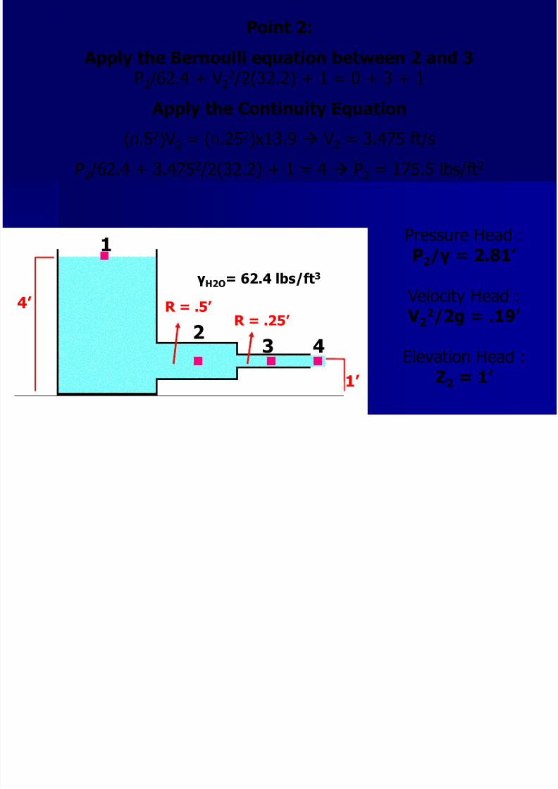
Point 2:
Apply the Bernoulli equation between 2 and 3P2 /62.4 + V2
2 /2(32.2) + 1 = 0 + 3 + 1
Apply the Continuity Equation
(Π.52)V2 = (Π.252)x13.9 V2 = 3.475 ft/s
P2 /62.4 + 3.4752 /2(32.2) + 1 = 4 P2 = 175.5 lbs/ft2
R = .5’ R = .25’
Pressure Head :P2/γ = 2.81’
Velocity Head : V 2
2/2g = .19’
Elevation Head :Z2 = 1’
8/3/2019 Fluid Mechanics Benno 7
http://slidepdf.com/reader/full/fluid-mechanics-benno-7 17/25
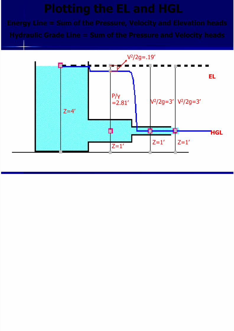
Plotting the EL and HGLEnergy Line = Sum of the Pressure, Velocity and Elevation heads
Hydraulic Grade Line = Sum of the Pressure and Velocity heads
EL
HGL
Z=1’ Z=1’ Z=1’
V2 /2g=3’ V2 /2g=3’
Z=4’
P/γ =2.81’
V2 /2g=.19’
8/3/2019 Fluid Mechanics Benno 7
http://slidepdf.com/reader/full/fluid-mechanics-benno-7 18/25
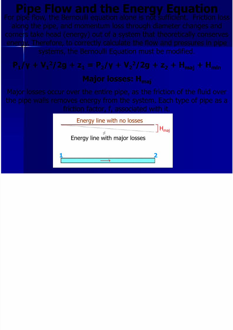
Pipe Flow and the Energy EquationFor pipe flow, the Bernoulli equation alone is not sufficient. Friction loss
along the pipe, and momentum loss through diameter changes andcorners take head (energy) out of a system that theoretically conserves
energy. Therefore, to correctly calculate the flow and pressures in pipesystems, the Bernoulli Equation must be modified.
P1/γ + V 12/2g + z1 = P2/γ + V 2
2/2g + z2 + Hmaj + Hmin
Major losses: Hmaj Major losses occur over the entire pipe, as the friction of the fluid overthe pipe walls removes energy from the system. Each type of pipe as a
friction factor, f, associated with it.
Hmaj Energy line with no losses
Energy line with major losses
1 2
8/3/2019 Fluid Mechanics Benno 7
http://slidepdf.com/reader/full/fluid-mechanics-benno-7 19/25
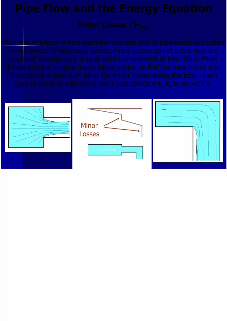
Pipe Flow and the Energy Equation
Minor Losses : Hmin
Momentum losses in Pipe diameter changes and in pipe bends are calledminor losses. Unlike major losses, minor losses do not occur over thelength of the pipe, but only at points of momentum loss. Since Minorlosses occur at unique points along a pipe, to find the total minor lossthroughout a pipe, sum all of the minor losses along the pipe. Each
type of bend, or narrowing has a loss coefficient, K L to go with it.
MinorLosses
8/3/2019 Fluid Mechanics Benno 7
http://slidepdf.com/reader/full/fluid-mechanics-benno-7 20/25
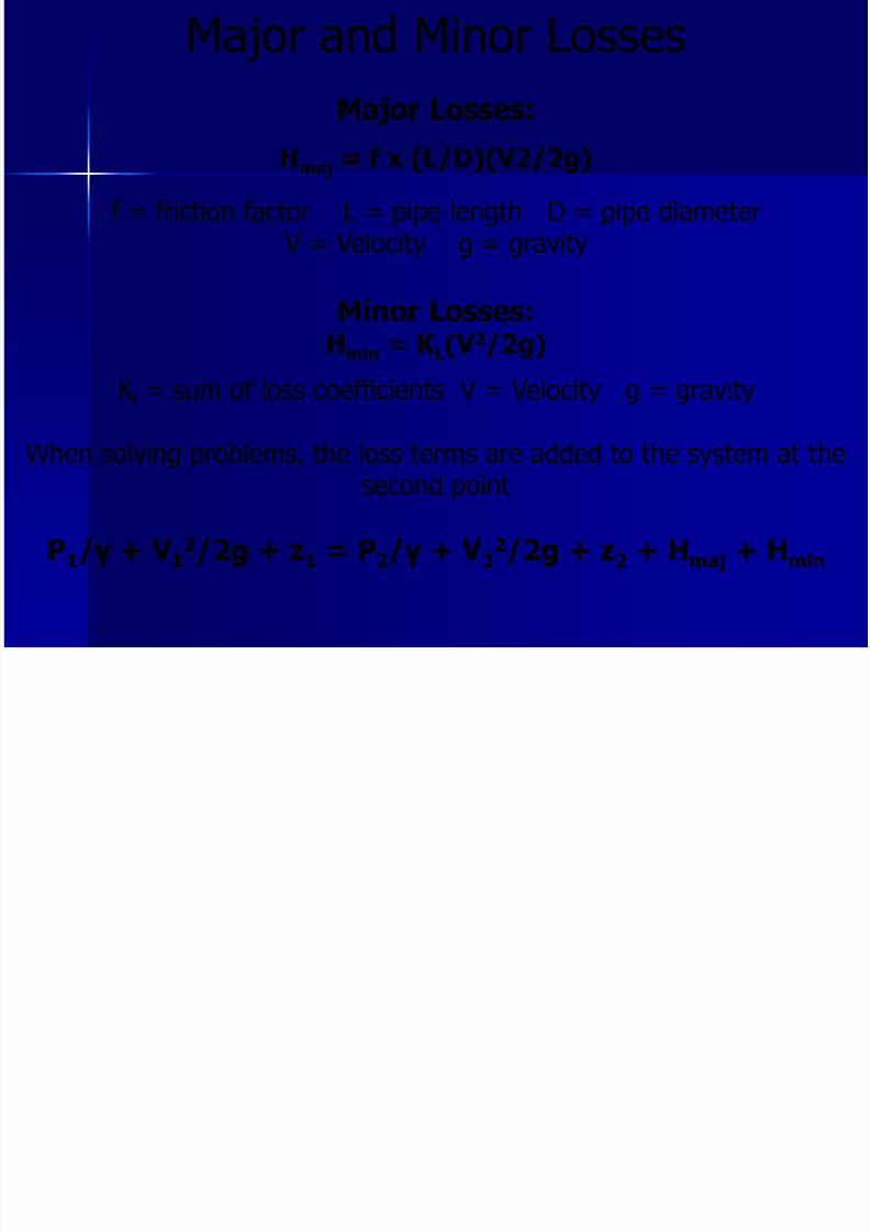
Major and Minor Losses
Major Losses:
Hmaj = f x (L/D)(V2/2g)
f = friction factor L = pipe length D = pipe diameter V = Velocity g = gravity
Minor Losses:Hmin = K L(V 2/2g)
K l = sum of loss coefficients V = Velocity g = gravity
When solving problems, the loss terms are added to the system at thesecond point
P1/γ + V 12/2g + z1 = P2/γ + V 2
2/2g + z2 + Hmaj + Hmin
8/3/2019 Fluid Mechanics Benno 7
http://slidepdf.com/reader/full/fluid-mechanics-benno-7 21/25
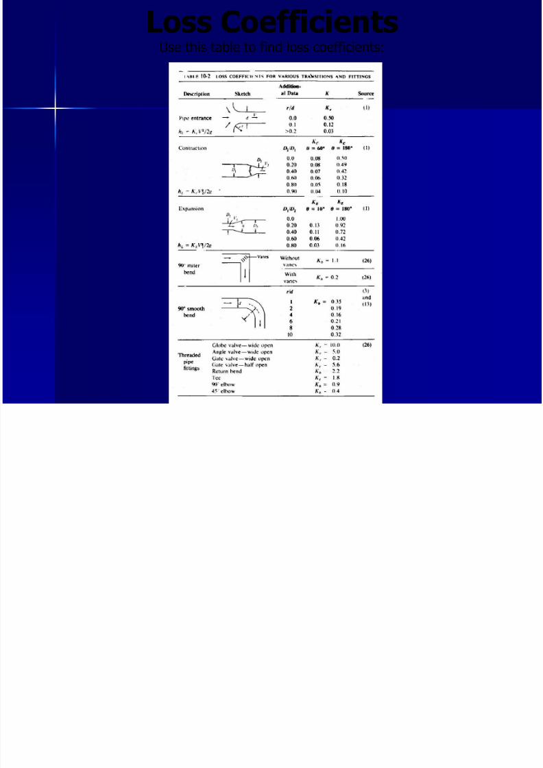
Loss Coefficients
Use this table to find loss coefficients:
i l l
8/3/2019 Fluid Mechanics Benno 7
http://slidepdf.com/reader/full/fluid-mechanics-benno-7 22/25
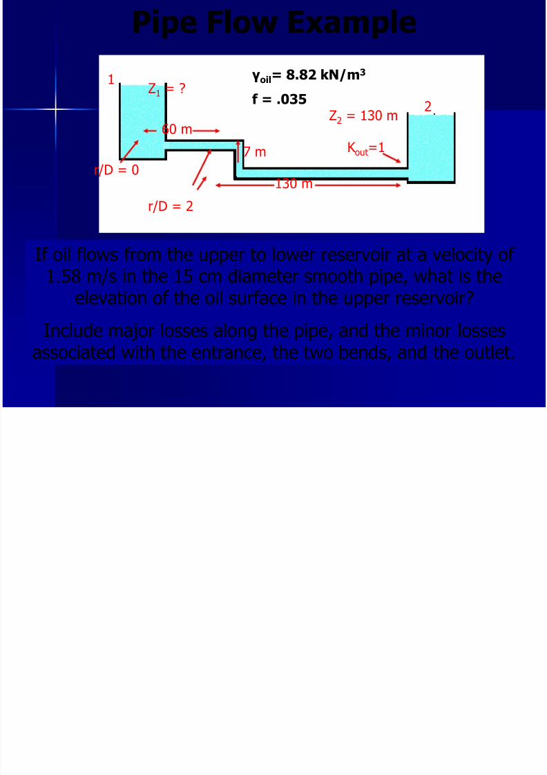
Pipe Flow Example
1
2Z2 = 130 m
130 m
7 m
60 m
r/D = 2
Z1
= ?γoil= 8.82 kN/m3
f = .035
If oil flows from the upper to lower reservoir at a velocity of 1.58 m/s in the 15 cm diameter smooth pipe, what is the
elevation of the oil surface in the upper reservoir?
Include major losses along the pipe, and the minor lossesassociated with the entrance, the two bends, and the outlet.
K out=1
r/D = 0
i l l

8/3/2019 Fluid Mechanics Benno 7
http://slidepdf.com/reader/full/fluid-mechanics-benno-7 23/25
Pipe Flow Example
1
2Z2 = 130 m
130 m
7 m
60 m
r/D = 2
Z1
= ?γoil= 8.82 kN/m3
f = .035
K out=1
r/D = 0
Apply Bernoulli’s equation between points 1 and 2: Assumptions: P1 = P2 = Atmospheric = 0 V1 = V2 = 0 (large tank)
0 + 0 + Z1 = 0 + 0 + 130m + Hmaj + Hmin
Hmaj = (fxLxV2) /(Dx2g)=(.035 x 197m x (1.58m/s)2)/(.15 x 2 x 9.8m/s2)
Hmaj= 5.85m
Pi Fl E l
8/3/2019 Fluid Mechanics Benno 7
http://slidepdf.com/reader/full/fluid-mechanics-benno-7 24/25
Pipe Flow Example
1
2Z2 = 130 m
130 m
7 m
60 m
r/D = 2
Z1
= ?γoil= 8.82 kN/m3
f = .035
K out=1
r/D = 0
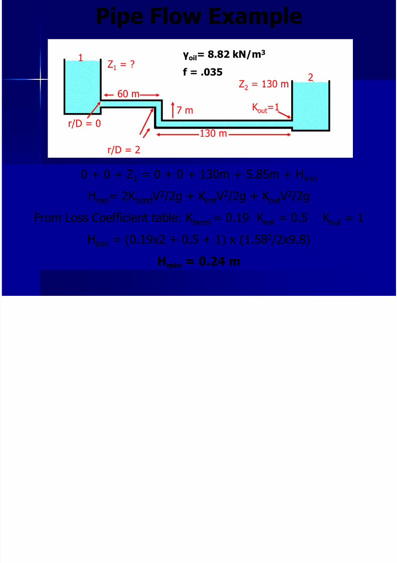
0 + 0 + Z1 = 0 + 0 + 130m + 5.85m + Hmin
Hmin= 2K bend V2 /2g + K ent V
2 /2g + K out V2 /2g
From Loss Coefficient table: K bend = 0.19 K ent = 0.5 K out = 1
Hmin = (0.19x2 + 0.5 + 1) x (1.582 /2x9.8)
Hmin = 0.24 m
Pi Fl E l

8/3/2019 Fluid Mechanics Benno 7
http://slidepdf.com/reader/full/fluid-mechanics-benno-7 25/25
Pipe Flow Example
1
2Z2 = 130 m
130 m
7 m
60 m
r/D = 2
Z1
= ?γoil= 8.82 kN/m3
f = .035
K out=1
r/D = 0
0 + 0 + Z1 = 0 + 0 + 130m + Hmaj + Hmin
0 + 0 + Z1 = 0 + 0 + 130m + 5.85m + 0.24m
Z1 = 136.09 meters