Embed Size (px)
Citation preview

Getting Started with pcDuino a learn.sparkfun.com tutorial
Contents
IntroductionHardware TourDVI Video FixSerial DebuggingWireless NetworkingTips and TricksChanging the OSGoing Further
Introduction
This article should give you a leg up on developing a project around the pcDuino. Getting started is easy: just plug in the cables, and away you go!
Okay, so that bit was easy. But what’s next? Now that you’ve got the machine up and running, what do you actually do with it?
We’re here to help. In the following pages, you’ll find some handy mini-tutorials to add features, change settings, write code, and just generally get more out of your pcDuino. All of these things assume that you’re running the standard Linux distribution that came with the pcDuino; as time goes by we’ll add some content covering Android as well.
Hardware Tour
Here’s a brief visual rundown of the hardware on the pcDuino.
Top side

Debugging serial port - a root-level session is initiated to this serial port at power up. It can be accessed as a 3.3V serial port, 8-N-1, no handshaking. For more information, see this page.Android buttons - these duplicate the functions of the hardware buttons on many Android-based tablets and phones. In Android programming, these buttons have a special function.GPIO - four 3.3V GPIO pins.SPI - two dedicated SPI peripheral headers. J6 is the SPI2 peripheral; J7 is the SPI0 peripheral, which is also broken out to the appropriate pins on the Arduino-ish headers. SPI0 pins also provide access to two more UARTs and external interrupts, as well.Arduino-ish headers - these pins closely follow the functionality of the pins on standard Arduino-compatible boards: I2C, SPI, UART, PWM, and ADC. The mapping is the same as it would be on a standard Arduino-compatible, as well, making it easy to convert Arduino shields to work with pcDuino.
Bottom side

MicroUSB power port - this port is for power only- the data pins don’t connect to anything. The board uses about 500mA under normal circumstances, meaning it can be powered from most USB ports; most modern cellular phone chargers use microUSB as well, making finding a power supply easy.USB-OTG port - this port can be used either as a standard USB port (with the appropriate converter) or to connect the pcDuino to another PC for debugging and upgrading the onboard software. The board can be powered through this port for debugging.
DVI Video Fix
The first-generation pcDuino has an issue with its display setup, which causes it to fail to properly display images on some DVI monitors. In future hardware revisions, this fix will ship with the device; for now, you may need to apply it manually.
Download these files to the root directory of a USB flash drive or microSD card:
dvi_20130225.tgzupdate_for_dvi
If your display is working, but the color is “off”, follow these instructions:
Insert the USB drive or microSD card into the pcDuino.Launch LXTerminal from the link on the pcDuino desktop.
Enter the following commands at the prompt:
cd /media/*sudo bash ./update_for_dvi
The patch will be applied automatically; it takes a few seconds. You should get a message stating that the pcDuino will restart in 10 seconds; after the restart, the problem should be solved.
If you cannot see the image on your display, the process is slightly more complicated. You’ll need to connect to the onboard serial debugging port. For instructions on how to do this, visit this page.
Now go ahead and connect the power to the pcDuino. You should see the light next to the reset button (between the HDMI and Ethernet ports) come on, and text should start scrolling by in the console. If that doesn’t happen, you may need to check the connection between your pcDuino and the serial bridge to make sure the wires are in right.
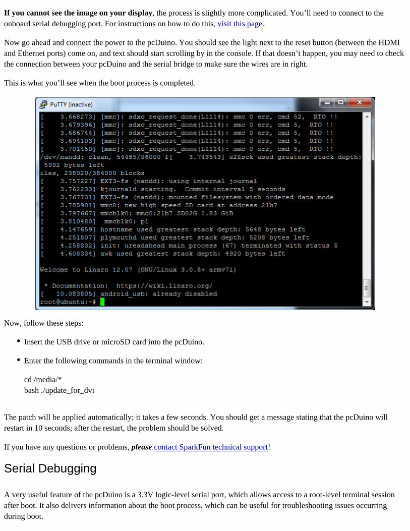
This is what you’ll see when the boot process is completed.
Now, follow these steps:
Insert the USB drive or microSD card into the pcDuino.
Enter the following commands in the terminal window:
cd /media/*bash ./update_for_dvi
The patch will be applied automatically; it takes a few seconds. You should get a message stating that the pcDuino will restart in 10 seconds; after the restart, the problem should be solved.
If you have any questions or problems, please contact SparkFun technical support!
Serial Debugging
A very useful feature of the pcDuino is a 3.3V logic-level serial port, which allows access to a root-level terminal session after boot. It also delivers information about the boot process, which can be useful for troubleshooting issues occurring during boot.

Connecting to this is simple, and there are many options for doing so. Here, I’ll give you instructions on using an FTDI Basic board, an FTDI cable, or an Arduino-compatible board. You’ll need either some female-male jumper wires or (second best option) some male header pins and female-female jumper wires.
FTDI Basic
The FTDI Basic connection is easy, since the pins on the FTDI Basic board are labeled.

FTDI Cable
The FTDI cable has no label on the connector, but the pinout is (for this use, anyway) the same as that for the FTDI Basic.
Arduino-Compatible board
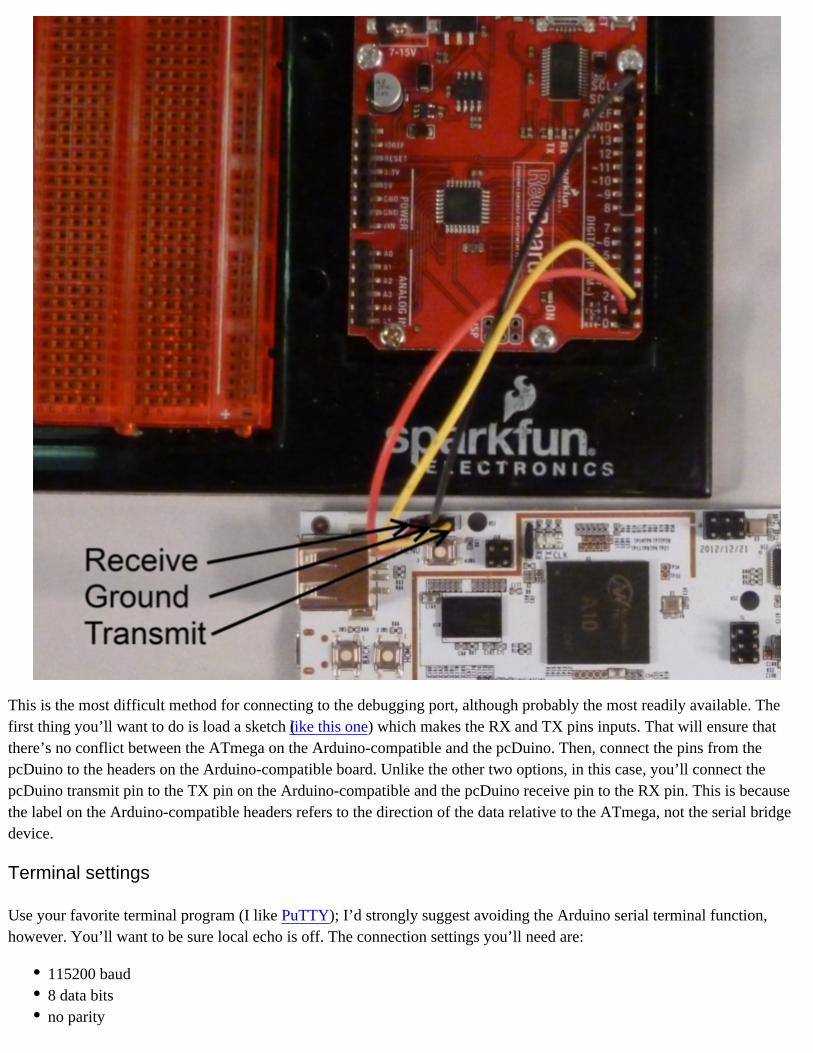
This is the most difficult method for connecting to the debugging port, although probably the most readily available. The first thing you’ll want to do is load a sketch (like this one) which makes the RX and TX pins inputs. That will ensure that there’s no conflict between the ATmega on the Arduino-compatible and the pcDuino. Then, connect the pins from the pcDuino to the headers on the Arduino-compatible board. Unlike the other two options, in this case, you’ll connect the pcDuino transmit pin to the TX pin on the Arduino-compatible and the pcDuino receive pin to the RX pin. This is because the label on the Arduino-compatible headers refers to the direction of the data relative to the ATmega, not the serial bridge device.
Terminal settings
Use your favorite terminal program (I like PuTTY); I’d strongly suggest avoiding the Arduino serial terminal function, however. You’ll want to be sure local echo is off. The connection settings you’ll need are:
115200 baud8 data bitsno parity

1 stop bitno handshaking
Wireless Networking
The minimalist Linux installation that comes with the pcDuino supports wireless networking, but you’ll have to get your hands a little dirty to get it to work. Here’s a walkthrough for getting the USB wifi dongle we sell working with your pcDuino:
Boot the pcDuino.
Plug in the dongle.
Open the “Network Connections” utility, under the “Preferences” submenu in the system menu.
Under the “Wireless” tab, click the “Add” button.
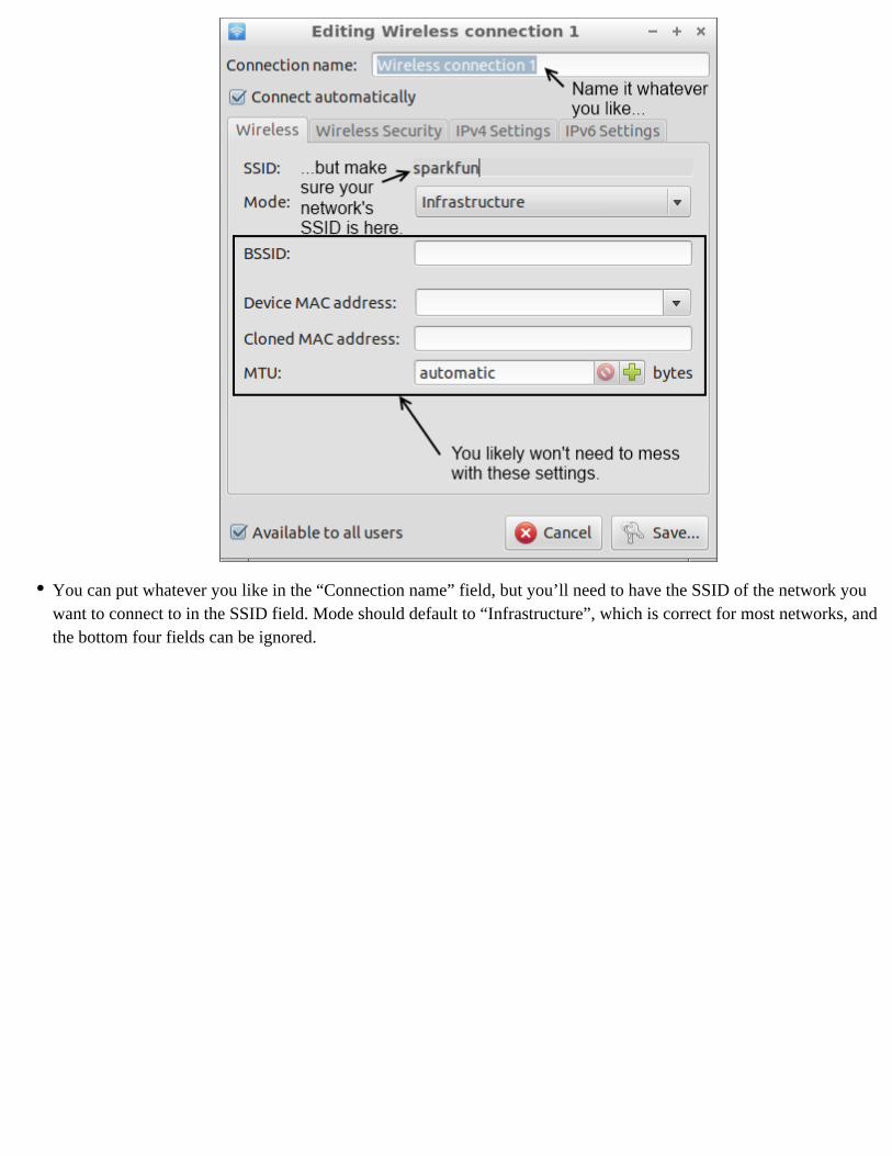
You can put whatever you like in the “Connection name” field, but you’ll need to have the SSID of the network you want to connect to in the SSID field. Mode should default to “Infrastructure”, which is correct for most networks, and the bottom four fields can be ignored.

In the “Wireless Security” tab, you can set the network security options for your network. We won’t attempt to cover this, because it’s too big a topic; the fields should be pretty similar to those on other devices, so copy the settings from something else if necessary.
The last two tabs, “IPV4 Settings” and “IPV6 Settings”, you can probably ignore. If you do need to use them, you likely know that you do, and you probably quit reading this page a while ago.
Hit the “Save” button to return to the “Network Connections” utility. You’ll see your new connection in the list; the “Last Used” column will say “never” next to this connection. That’s okay. Go ahead and close the window and your connection should be ready to go!
Tips and Tricks
Now that you’re up and running, there are a few things you may find useful to do immediately.
Change/disable screensaver timeout
The default screensaver settings will cause the monitor to blank almost immediately after boot. If that’s not to your liking, here’s how to change it.
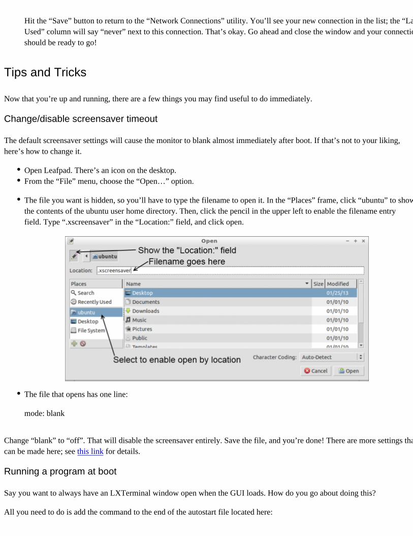
Open Leafpad. There’s an icon on the desktop.From the “File” menu, choose the “Open…” option.
The file you want is hidden, so you’ll have to type the filename to open it. In the “Places” frame, click “ubuntu” to show the contents of the ubuntu user home directory. Then, click the pencil in the upper left to enable the filename entry field. Type “.xscreensaver” in the “Location:” field, and click open.
The file that opens has one line:
mode: blank
Change “blank” to “off”. That will disable the screensaver entirely. Save the file, and you’re done! There are more settings that can be made here; see this link for details.
Running a program at boot
Say you want to always have an LXTerminal window open when the GUI loads. How do you go about doing this?
All you need to do is add the command to the end of the autostart file located here:
/etc/xdg/lxsession/Lubuntu/autostart
For instance, to launch LXTerminal at boot, add the line “lxterm” to the end of the file.
Stopping the GUI from automatically loading on boot
If you’re using a pcDuino in an embedded application, it may be helpful to prevent the GUI from loading, to conserve processor resources. To log in only as root, with access only via the debugging serial port, open this file:
/etc/lightdm/lightdm.conf
Delete all of the content after [SeatDefaults]. This will stop it from launching the window manager and logging you in.
If you only want to stop the automatic login, just remove the last line (“autologin-user=ubuntu”) from the file, and you’ll be presented with a login screen at reboot.
Changing the OS
The last thing you might be interested in doing is reloading or changing the operating system on the device. There are two methods for doing this: LiveSuit (sometimes found on the internet as “LiveSuite”) and PhoenixCard. LiveSuit can be used to load either Lubuntu or Android; PhoenixCard can only be used to load Linux. We’ll only be covering LiveSuit, as it is the easier and preferred means for doing this.
LiveSuit is available in a Windows (32-bit) version, a Windows 7 (64-bit) version, or in a Linux (64-bit-only) version. We’ll skip over installation of the tool; the linked website explains how to install the Linux version, and the Windows versions don’t need to be installed, merely extracted.
You’ll also need the appropriate image file. Here’s the Lubuntu image that ships with the pcDuino, and this Android image can be loaded as well.
Installing drivers (Windows only)
Before going any farther, you should install the drivers for the pcDuino debugging port. Make sure that you have the right version of LiveSuit–the drivers in the 32-bit version won’t work on a 64-bit system!
Plug a microUSB cable into your computer. While holding the button marked SW2 on your pcDuino, plug the other end of the cable into the USB-OTG port on your pcDuino.

In Windows XP, you’ll see a driver installation query pop up. In Windows 7, you’ll probably have to open the device manager. The device will appear as “USB Device(VID_1f3a_PIDefe8)” under the “Universal Serial Bus controllers” section. The drivers are in the LiveSuit directory, in the “UsbDriver” directory.
Once driver installation has completed, unplug the pcDuino.
Installing Android
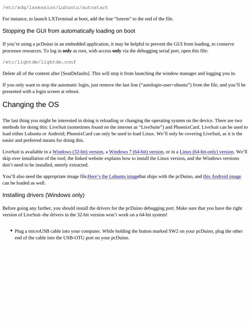
Launch the LiveSuit application.Select the Android image file you downloaded above.
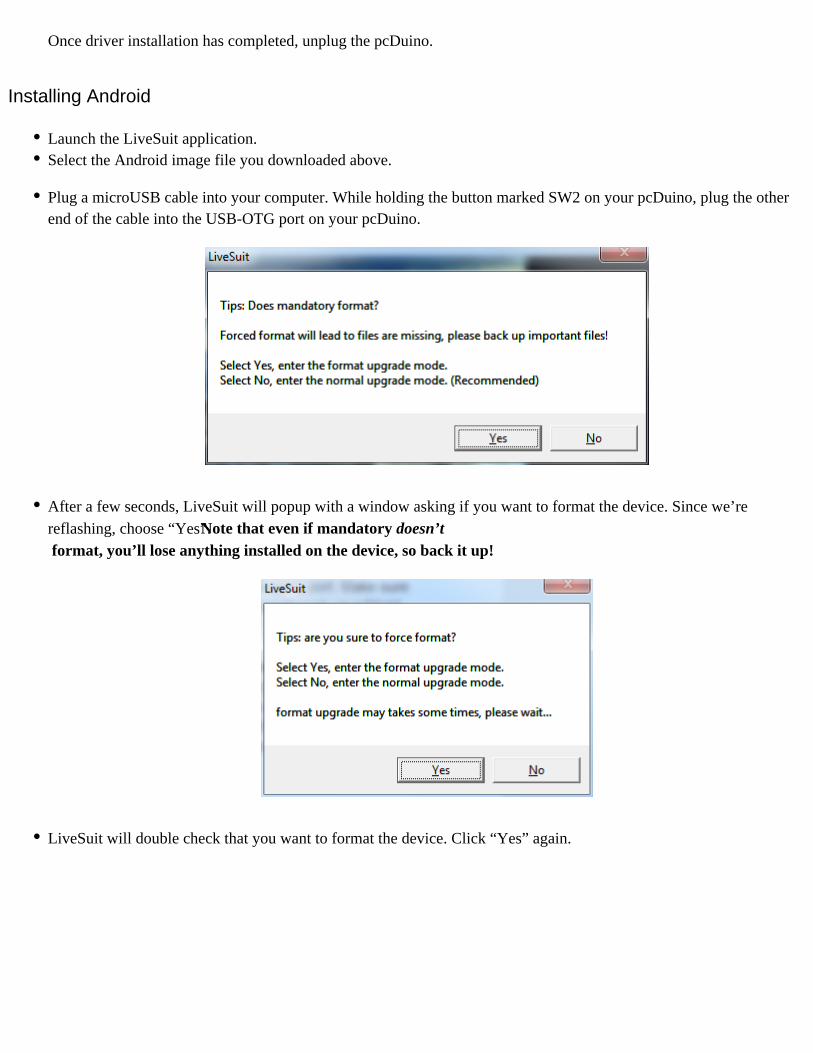
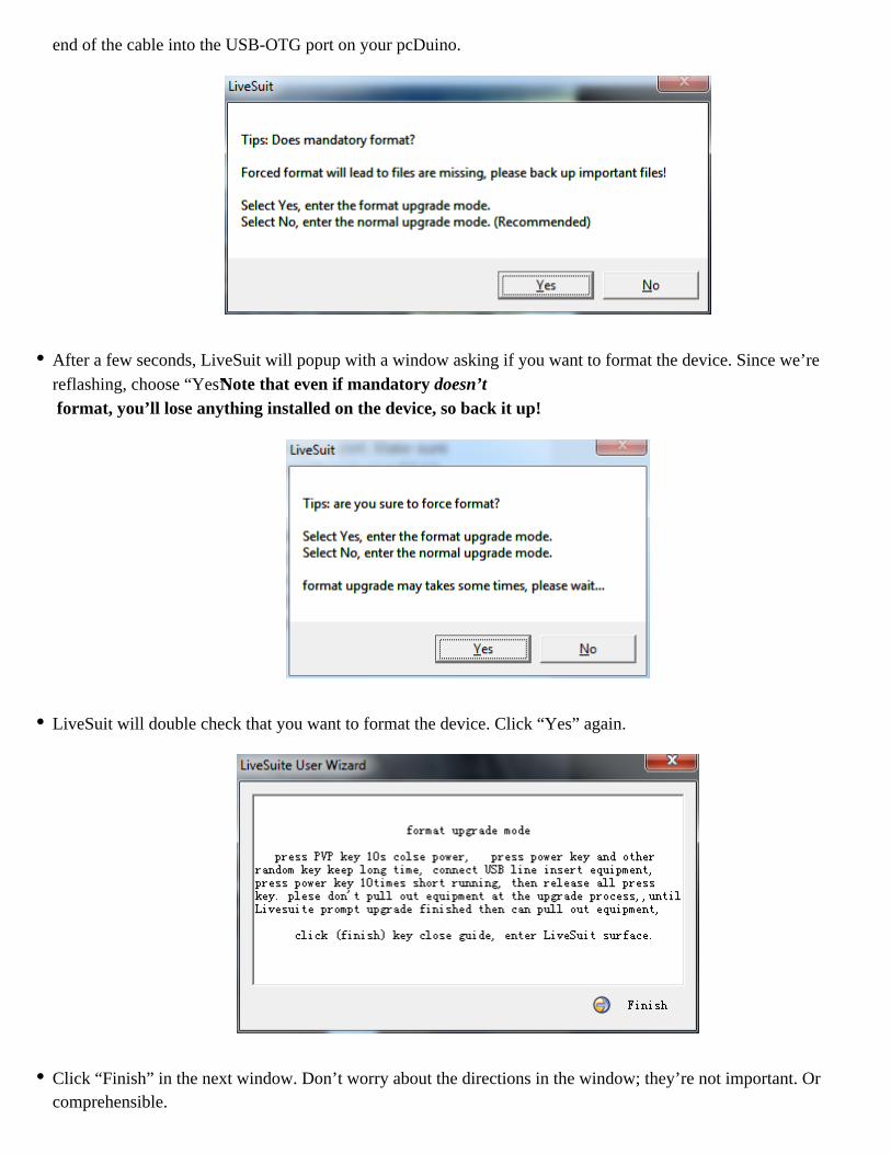
Plug a microUSB cable into your computer. While holding the button marked SW2 on your pcDuino, plug the other end of the cable into the USB-OTG port on your pcDuino.
After a few seconds, LiveSuit will popup with a window asking if you want to format the device. Since we’re reflashing, choose “Yes”. Note that even if mandatory doesn’t format, you’ll lose anything installed on the device, so back it up!
LiveSuit will double check that you want to format the device. Click “Yes” again.

Click “Finish” in the next window. Don’t worry about the directions in the window; they’re not important. Or comprehensible.
The progress bar will fill in, and if you’ve got a connection on the serial port terminal, you can watch the progress there as well. Don’t be alarmed if there are some long pauses during the update, although the whole process should not take more than five minutes.
LiveSuit will give you an “Update success” window, and the pcDuino will automatically reboot into Android. Note that when watching the serial debugger port output, Android doesn’t give you any kind of a prompt–just a blank line, into which you can enter commands.
Installing Ubuntu
Launch the LiveSuit application.Extract the Ubuntu archive you downloaded above. In it are two image files: “a10_kernel_20130203.img” and “ubuntu_20130203.img”. Select the “a10_kernel_20130203.img” file.Copy the files “env_nandd.fex”, “ubuntu_20130203.img”, and “update.sh” from the Ubuntu directory you just extracted to either a microSD card or a flash drive. Make sure the files are in the root directory of the drive!Insert the flash drive or microSD card into the pcDuino.
Plug a microUSB cable into your computer. While holding the button marked SW2 on your pcDuino, plug the other
end of the cable into the USB-OTG port on your pcDuino.
After a few seconds, LiveSuit will popup with a window asking if you want to format the device. Since we’re reflashing, choose “Yes”. Note that even if mandatory doesn’t format, you’ll lose anything installed on the device, so back it up!
LiveSuit will double check that you want to format the device. Click “Yes” again.
Click “Finish” in the next window. Don’t worry about the directions in the window; they’re not important. Or comprehensible.

The progress bar will fill in, and if you’ve got a connection on the serial port terminal, you can watch the progress there, as well. Don’t be alarmed if there are some long pauses during the update, but it won’t take more than five minutes to complete.
LiveSuit will open an “Update success” message. Do not disconnect the power from the pcDuino at this time.
If you’re connected to the serial monitor, you can watch the device update from the external memory. It takes some time–several minutes at least–and at the end, an “update complete” message will appear on the serial monitor.
If you’re not connected to the serial monitor, you’ll know the update process is completed when the RXLED and TXLED will blink slowly, in unison. While the upgrade is underway, RX will be solid on and TX will be blinking.
Once the upgrade is complete, you may restart the pcDuino.
Going Further
Here are a few links that may be useful:
pcDuino.com - The official pcDuino websiteLubuntu - This is the Linux distribution that comes with the pcDuinoTech specs on the processor - Allwinner isn’t terribly forthcoming about the A10 processor on this board, but this website has some good resources about it.LXDE - The desktop manager installed by defaultpcDuino on GitHub - The official GitHub repo for the Arduino-compatibility features on the pcDuino

SparkFun’s pcDuino repository - For work from within SparkFunChanging the pcDuino display resolution - Written by one of our customers. Thanks Bill!
learn.sparkfun.com | CC BY-SA 3.0 | SparkFun Electronics | Boulder, Colorado