Embed Size (px)
Citation preview

UPTEC IT 09 015
Examensarbete 30 hpSeptember 2009
Graphical Interface Framework for Control System Environments
Jonas Lindholm


Teknisk- naturvetenskaplig fakultet UTH-enheten
Besöksadress: Ångströmlaboratoriet Lägerhyddsvägen 1 Hus 4, Plan 0
Postadress: Box 536 751 21 Uppsala
Telefon:018 – 471 30 03
Telefax: 018 – 471 30 00
Hemsida:http://www.teknat.uu.se/student
Abstract
Graphical Interface Framework for Control SystemEnvironments
Jonas Lindholm
Industry machines and vehicles are becoming more and more complex and are todayoften operated through a control system. Such control system must be able tooperate in rough environments. It is also becoming more and more common thatthese systems make use of a display to present and control the system. In such case agraphical user interface (GUI) will be built. Controller Development System(CoDeSys) is a development environment platform for control systems. It handlesdevelopment of automation as well as GUIs.
Today CoDeSys exists in two versions, CoDeSys V2 and CoDeSys V3. This thesisconducts a qualitative evaluation and comparison of these to platforms. Theevaluation covers the basic functionality of the two platforms, the developmentenvironments, how custom elements can be built and integrated, and a performancetest. The focus of the evaluation is put on how custom element development is doneand the performance test. The comparison shows that both platforms supportdevelopment of custom elements, but also that the newer version of CoDeSys takenthe process one step further. As for performance the result shows that unless GUIsare built in certain ways the working load for the control system will be too high.
Tryckt av: Reprocentralen ITCISSN: 1401-5749, UPTEC IT09 015Examinator: Anders JanssonÄmnesgranskare: Bengt SandbladHandledare: Tobias Andersson


Table of contents 1 Introduction and Background ............................................................................... 5
1.1 Purpose ............................................................................................................. 5 1.2 Method .............................................................................................................. 5 1.3 Delimitations ..................................................................................................... 7 1.4 Source Evaluation ............................................................................................. 8 1.5 Name guideline ................................................................................................. 8
2 Environment of operation ..................................................................................... 9
2.1 The CCP XS .................................................................................................... 10 2.2 CoDeSys (Controller Development System) ................................................... 10
2.2.1 IEC 61131-3 ............................................................................................. 11 3 Platform Goals ..................................................................................................... 12 4 Evaluation of CoDeSys V2 .................................................................................. 13
4.1 Development environment .............................................................................. 13 4.2 Visualizations .................................................................................................. 14 4.3 Basic elements ................................................................................................ 14 4.4 Advanced elements ......................................................................................... 15 4.5 Custom element API ....................................................................................... 16
4.5.1 Communication with CoDeSys ................................................................. 16 4.5.2 Element structure ..................................................................................... 16 4.5.3 Available components .............................................................................. 17
4.6 Limitations ....................................................................................................... 17 4.7 Performance ................................................................................................... 17
4.7.1 Element types ........................................................................................... 19 4.7.2 Visualization cycle measurements ............................................................ 19 4.7.3 Multiple elements measurements ............................................................. 20
5 Evaluation of CoDeSys V3 .................................................................................. 21
5.1 Development environment .............................................................................. 21 5.2 Elements ......................................................................................................... 22 5.3 Custom element API ....................................................................................... 22
6 Comparison and results ...................................................................................... 23
6.1 Support development of custom element ........................................................ 23 6.1.1 Integration in the platform ......................................................................... 23 6.1.2 Means to distribute and install .................................................................. 23 6.1.3 Simplicity and Adoptability ........................................................................ 24
6.2 Performance criteria ........................................................................................ 24 6.3 Custom element development tool .................................................................. 24 6.4 Development environment .............................................................................. 25
7 Conclusion ........................................................................................................... 26 8 Future work .......................................................................................................... 27 9 References ........................................................................................................... 28

9.1 Bibliography .................................................................................................... 28 9.2 Other printed references ................................................................................. 28 9.3 Electronic references ...................................................................................... 28 9.4 Oral and email communication ........................................................................ 29
10 Appendix ............................................................................................................ 30
10.1 Appendix I: Dictionary ................................................................................... 30 10.2 Appendix II: Custom element communication with CoDeSys ........................ 30 10.3 Appendix III: Element IDs for custom elements ............................................ 31
10.3.1 Resource.h ............................................................................................. 31 10.3.2 globals.h ................................................................................................. 31 10.3.3 ElementDLL.cpp ..................................................................................... 31
10.4 Appendix IV: VisualElem Class References .................................................. 32 10.5 Appendix V: IVisualElement Interface References ........................................ 34

Foreword I would like to thank my supervisor at CC Systems, Tobias Andersson, for all the guidance and support he has provided during my thesis time at CC Systems. I would also like to thank CC Systems in general for taking on my thesis project, it has been a great experience. Andreas Wikensjö, thank for showing me around the office as a fellow thesis student when I started out.


5
1 Introduction and Background In today’s industrial machines and vehicles embedded systems has become more and more common. The systems are used for everything from collecting and handling large amount of diagnostic data to navigate and control the machines. Cross Country Systems AB (henceforth CC Systems) develops and delivers advanced control systems for industrial vehicles and machines in rough environments, with the aim to make them more reliable, intelligent and productive. Examples of machines they deliver systems for are container spreaders, forestry machines, mining equipment and trains. The company has several offices and facilities located in Sweden, Finland and Malaysia where they cover both hardware and software development of the systems to production. (http://www.cc-systems.com/) The control systems software is often built with the software platform Controller Development System (henceforth CoDeSys) developed by 3S – Smart Software Solutions (henceforth 3S). This platform provides a software-Programmable Logical Controller, or soft-PLC, which is a program that handles signals for controlling machines. In a lot of today’s cases the control system uses a display. In such a case CC Systems or its customer designs a Graphical User Interface (GUI) using CoDeSys Visualization editor (CoDeSys Visu). CoDeSys Visu has a natural connection to the CoDeSys runtime which makes the development of GUIs simple and intuitive by allowing easy access to Input/Output (I/O) data and offering a set of simple standard components. (CC Systems, 2008) Today CoDeSys exists in two versions, Version 2 (V2) and Version 3 (V3). Development for CoDeSys V2 is discontinued but 3S still offers support for the system, while all new development is done on CoDeSys V3. CC Systems products are currently compatible with CoDeSys V2 and a transition to start develop with CoDeSys V3 would require an investment in time to port the soft PLC to CC Systems products. (Andersson, 2009a) There have been some thesis projects involving CoDeSys earlier. However they have been looking at the possibility to connect external GUIs with application software built in CoDeSys or how to port CoDeSys to a specific platform. The possibilities within the CoDeSys Visu platform have thus not been explored to a great extent.
1.1 Purpose The focus of this thesis project is to evaluate the platforms CoDeSys Visu V2 and CoDeSys Visu V3. CC Systems want to explore the possibilities of the platforms, if it fulfils their requirements and how it fits in their graphical framework. More specifically there is a need to support development of custom elements in order to produce a customized graphical profile. The elements should furthermore have the properties to integration naturally in the CoDeSys platform, be able to distribute and install target customer systems, and sustain simplicity and adoptability. Hence possibility of creating such custom elements will be investigated. There is also criterion on performance of the platform which is tested. (CC Systems, 2008)
1.2 Method To evaluate the CoDeSys Visu platform a qualitative evaluation method is used. Traditionally technical evaluations have adopted the qualitative ways of evaluating. Sometime during the

6
nineties the qualitative process became more accepted and popular (Hoepfl, 1997). There has been a lot of researching on the subject of quantitative evaluation. One researcher that has examined the paradigm is for example Michael Quinn Patton (1990). The qualitative research can be any research that realizes its findings without any statistical procedures or other quantifications, as opposed to the quantitative research paradigm where hard measurements is preferred. (Hoepfl, 1997)
The way I have decided to perform the evaluation is adopted from a method explained by Cronholm & Goldkuhl (2003). The evaluation is done by defining a set of specific goals for the system, and then determines if the system fulfils these goals. These goals are derived from a human or organizational context and will puts a focus on the system fulfilling the task it is intended for. This method is then used in combination with the quantitative research paradigm explained by Hoepfl (1997). Hoepfl defines nine steps of how to design a research, these steps has been used to outline the method. This method allows me to act as an expert evaluator by examining the system at hand (Cronholm & Goldkuhl, 2003). CC Systems has a clear idea of what they want their platform to achieve. The platform goal, discussed in section 3, specifies the requirements for the evaluation. Another reason for the use of this paradigm is that there are no real user cases to observe. The purpose of the thesis is not to perform a usability test, how an operator interacts with the platform, but what possibilities the platform itself possess. For example, can the platform offer support to create a customized profile of elements? The questions allows for empiric investigation off the platform and its documentation, as opposed to observations of user cases. It lets me, the researcher, act as a human instrument of data collection. The research design, adopted from the nine steps defined by Hopfels (1997), is now described. The data needed for the evaluation has been acquired by studying the platforms documentation as well as a series of open-ended interviews with CC Systems employees and email conversations with employees at 3S. Both the people at CC Systems and 3S has been working with CoDeSys for a long time, 3S is even the company developing the platform, and can thus be view as experts on the system. Remaining questions, which has been unanswered by CC Systems and 3S, has been empirically tested on the platform. The study has been divided into three phases. The first phase was to establish the platform goals, which the study has been based on. This was partially already done since there was a specification from CC Systems side on what they wanted to investigate, but the goals had to be untangled and some missing information had to be gathered. The second phase was to evaluate CoDeSys Visu V2. In order to do this I had to start by getting familiar with the platform. This was done by studying the platform documentation, examining old GUIs developed by CC Systems and examining the custom elements API. There is little documentation on how the custom elements API works so I had to empirically test it by constructing a few components. These components where later used for the performance test, which is also the last part of the evaluation of CoDeSys Visu V2. When all this information was gathered the evaluation was conducted. In the same fashion CoDeSys Visu V3 was examined and evaluated. The difference here was that no performance test was done due to technical reasons, more on this in section 1.3. The

7
custom element API for CoDeSys Visu V3 has no documentation at all, when the thesis started the API was not even released. Instead I had Lars Lodin at Best Engineering Scandinavia demonstrate it during an interview. I have been looking at the same key features for both platforms when making the evaluation in order to be able to perform a fair comparison. You will see in the evaluation parts that some things are brought up for one platform but not the other, this has been necessary in order to enlighten the differences of the platform. Especially in CoDeSys Visu V3 there are some new features that do not appear in CoDeSys Visu V2 that are of great value. The last phase of the study is the actual analysis. The analysis consists of a compression of the two platforms in order to distinguish them from each other. This is done by applying the platform goals, defined in section 3, on the result from the evaluation to see if and how the goals are achieved. The method presented fits the purpose of this paper relatively good. The drawback is that it relies heavily on the evaluator making the correct decision or appreciation, the method is no better then the evaluator. Since I act as the expert evaluator, and are aware of the importance of me staying objective, I will focus on not let subjective judgment affect the outcome of the study. To be source critical is one way to prevent misjudgement, the importance of this is brought up in section 1.4. Another aspect the method lacks is the input of users and usability tests. I have already stated that the purpose of the thesis is not to perform a usability test, which will be discussed further in section 1.3. Regarding input of users CC Systems employees can be viewed as users. Since a lot of information used in the evaluation comes from them the aspects of the users are included by indirect means.
1.3 Delimitations A delimitation to only look at CoDeSys Visu V2 and CoDeSys Visu V3 has been made. There could have been other graphic platforms involved in the evaluation, such as Qt (http://www.qtsoftware.com/). This would have given an interesting perspective on how CoDeSys distinguishes itself from another platform. This however has not been included due to the following reasons. First of all it would give the thesis a different focus. Instead of the main focus being on how CoDeSys Visu V3 distinguishes from CoDeSys Visu V2, which has been CC Systems aim, it would be on how different platforms build GUIs. Secondly CoDeSys consists of several parts, the visualization editor being one. If another platform was used for GUI development remaining parts of the control system would still be developed in CoDeSys. So extracting the GUI from CoDeSys would create a need of a signal layer between the GUI and CoDeSys. Developing such a layer would require a thesis of its own. With that said a complete development environment is a key reason for choosing CoDeSys Visu over another graphical platform (Andersson, 2009a). As mentioned earlier the purpose of the thesis does not involve the aspect of usability, nor are any user cases done. I have chose to do so in order to get a clearer focus on the goals CC Systems has asked for. If the thesis were to evaluate the actual GUIs created usability would be a highly interesting aspect. Here I have been looking at the properties and possibilities of the platform; hence usability is not of such great importance. A performance test has only been done on the CoDeSys V2 platform. CoDeSys V3 is not used by CC Systems today and porting a soft PLC to CC Systems machines for this thesis is not a

8
viable option. Therefore there is no CoDeSys V3 soft PLC developed for the computer used to test the performance on.
1.4 Source Evaluation The documentation of the CoDeSys platforms is scarce. It mostly covers the basic functionality of the tool, although it is somewhat better for CoDeSys V2 then V3. Because of this a lot of the information has been gathered from the employees at CC Systems and 3S. With such sources comes a risk of bias, especially 3S has something to gain form selling their platform. All the information has thus been critically considered and tested in practice. The credibility of the report relies a lot on me, as the evaluator, making the appropriate decisions, due to the qualitative approach of the research methodology. Whether I am qualified as an evaluator is up to CC Systems, the client, to decide. Since they approved me to perform the study I can only assume they deem me qualified.
1.5 Name guideline So far in the paper the visualization part of CoDeSys has been distinguished from CoDeSys by calling it CoDeSys Visu. This has been done to point out that the visualization editor is only one part off CoDeSys. Exactly how CoDeSys works will be further explained in section 2.2. From now on CoDeSys will be used when referring to the platform whether it is the visualization editor being mentioned or some other part of the platform. CoDeSys V3 and CoDeSys V2 will be used to separate the two versions from each other.

9
2 Environment of operation CC Systems has developed several products which all are part of the control system platform CrossTalk. It consists of various hardware units designed for different purposes in a control system for example handling I/O, display data or send data over Bluetooth. Examples of such hardware units is the CrossFire, specified on handling hydraulic I/O, or CrossCode, specified on handling human machine interaction controls such as joysticks switches or LEDs. The communication is done via CANopen, a communication protocol specified for embedded system used in automation, which makes it easy for integration of third party hardware. CrossTalk utilizes CoDeSys. (CC Systems, 2007)
Examples of control systems based on CrossTalk CC Systems works with a variety of machines and systems. Each system has to be tailored to its machine, but the CrossTalk platform will lower the development time and cost of the system. The CrossTalk platform is targeted for competitive machines with advanced system functionality such as diagnostics, prognostics, GPS positioning and mobile communication. (CC Systems, 2007)

10
2.1 The CCP XS The Cross Country Pilot XS (CCP XS) is one of the on-board computers CC Systems offer in the CrossTalk platform and it has been used in this thesis project. It functions as the central component in a mobile control system. The CCP XS is light-weighted and has a slim design to fit in rough environments where it is meant to operate and can handle temperatures from -40oC to +65oC. It runs the operation system Windows Embedded Compact 5.0 (Windows CE) which is a version of Windows designed for minimalistic computers and embedded systems. (CC Systems, 2008)
The CCP XS
The CCP XS comes in three different models, basic, extended and all-integrated. I used an CCP XS all-integrated for this project with the technical specification as follows:
Processor Intel XScale, IXP425, 533 MHz
RAM Memory 256 MB SDRAM
Compact Flash Memory 1 GB
Operating System Windows CE 5.0
Display 10”4 Touch screen, SVGA 800x600
A specification of the essential technical data of the CCP XS use in the thesis project As stated in the specification the CCP XS comes with a 10”4 resistive touch screen. This opens up for a lot of possibilities when it comes to interaction and GUI design.
2.2 CoDeSys (Controller Development System) CoDeSys is a complete PLC development environment. It lets the developer create a complete system with only one tool. It offers tools to solve automation tasks, setup hardware components and display visualizations. A CoDeSys project consists of Program Organization Units (POU), data types, visualizations and recourses. One of the Recourses is the PLC Configuration, where you on a drag and drop basis can add and configure different hardware parts like a CrossCode or CrossFire to your PLC. When this is done the I/O-ports of these controls will automatically be added to the variable pool, where they can be used in the POUs. (3S-Software, 2009)

11
The communication between the PLC parts happens in a layer beneath CoDeSys over CANopen. The drivers for this is already implemented so when the developer wants to setup a new project the developer can focus on developing the application for the PLC and not having to start from scratch every time building a communication layer. This and the ease to develop automation software in CoDeSys will save the developer up to a month in development time not having to write his own CANopen stack. (Wahlström, 2009) Companies that develop products using CoDeSys are members of the CoDeSys Automation Alliance (CAA). These companies can share their products with each other and there will be no need to implement new drivers and such since they all use the same CANopen standard. If CC Systems products fail to solve a specific task asked for by a customer CC Systems could simply buy a product that will solve the task from a CAA member. (Wahlström, 2009) Compared to other platforms CoDeSys offers a relatively free environment. When using other PLC systems you might be locked to that company’s products and platform. The alternative to use a platform such as CoDeSys would be to develop everything from scratch. This would give the developer the freedom to create a system that operated exactly as he sees fit and there would be no limitation to what is possible. One has to keep in mind that developing something from scratch does require a lot of time. (Wahlström, 2009)
2.2.1 IEC 61131-3 The International Electrotechnical Commission (IEC) is an international standards organization that publishes standards for electrotechnologies. They have developed the IEC 61131-3 standard, which CoDeSys follows. The standard deals with PLC programming languages and defines four such languages. Two of them are graphical, Ladder Diagram (LD) and Function Block Diagram (FBD), the other two are textual, Structured Text (ST) and Instruction List (IL). While the graphical languages deals with circuits, IL, and function blocks, FBD, the textual languages resembles Pascal, ST, and an assembly language, IL. (Wikipedia, 2009)

12
3 Platform Goals The platform goals are what CC Systems wants their graphical platform to achieve. They are of both technical and more organizational nature. These goals will be the basis for what I look at when evaluating the platforms. When the evaluations are done the goals will be applied on the results and the two platforms will be compared. The main goal CC Systems has set up is the possibility to create their own graphical profile. This is presumably done by finding an approach to develop customized elements which will integrate naturally with the CoDeSys platform. As well as integration, distribution is an important feature of such profile. How would it be distributed and installed on CC Systems customers target systems. (Lans, 2009) The graphical profile developed should constitute simplicity. Simplicity, as defined by John Maeda (http://lawsofsimplicity.com/), is achieved through reducing, organizing and saving time. This is essential since the intended user of the profile is the customers of CC Systems. They are usually not software engineers and thus not always familiar with the concepts of GUI development. Simplicity being a sales argument is another reason for prioritizing it. Being able to show simple GUI creation with a good result is a selling point of a system which CC Systems want to utilize. (Lans, 2009; Wahlström, 2009) CC Systems products are developed for a variety of systems and sold to a diversity of companies. This demands certain adoptability from the components in the graphical profile (Wahlström, 2009). Adoptability in the sense that even though simplicity is a key feature of a component it is still possible for a component to adopt a specific theme to fit a GUI. Take a meter element for example, simplicity can be achieved by reducing and organizing the options needed for the scale, while adoptability can be achieved by offering a standard background as well as the option to select your own bitmap as background. The last criteria for the platform are that the GUIs created needs to have a reasonable performance on the CCP XS. This will be measured by looking at CPU usage. There is no hard criteria on what percentage is acceptable, what is asked for is an examination of how resource-demanding GUIs are and what parameters might effect this. (Andersson, 2009a) All in all we can distinguish the following goals for the graphical platform:
• Support development of custom elements with the following properties: o Integration in the platform o Means to distribute and install o Simplicity o Adoptability
• Criteria on performance of GUIs developed with the platform As reflected by the goals the ability to customize elements and develop advanced elements is important. CC Systems are already using, as stated earlier, CoDeSys V2 as their visualization platform today. They have realized that this platform, or the way they utilize it today, is not enough for their needs. This is why it is so important that there are possibilities for further development within the platform. (Andersson, 2009a)

13
4 Evaluation of CoDeSys V2 CoDeSys offers an integrated environment for both application and visualization development. Since everything is integrated in the same tool you can smoothly bind your application variables to the visualization element by accessing an input assistant dialog displaying all your variables and constants in your project. Hence no signal layer between application and visualization is needed, which often is difficult to configure. (3S-Software, 2007)
4.1 Development environment The development environment is divided into four main parts, the object organizer, the toolbar, the visualization objects and project output window, all shown below in figure 1. The object organizer contains a list of all visualization objects in the current project. A project can contain several visualization objects and they can be renamed and added from the object organizer. If opened visualization objects are displayed in the centre of the environment, you can see an open visualization object in figure 1. One visualization object is configured as the master layout and will be the start screen when the project runs. There are several elements, explained in section 4.1.2 and 4.1.3, available in the toolbar which can be added to a visualization object on a drag and drop basis. An element can be another visualization objects which makes it possible to create a GUI consisting of several pages. Finally there is the project output window which allows for compilation feedback and error message handling. (3S-Software, 2008)
Figure 1 - The CoDeSys V2 Visualization editor

14
4.2 Visualizations The position of all elements in a visualization are controlled from a master element list. This element list is a simple table with the columns number, type and position. The number and type is represented with an integer and a string while the position is a list of four integers representing the top left and bottom right corner of the element, {x1, y1, x2, y2}. (3S-Software, 2008) Another feature of a visualization is that it is possible to use a bitmap as background. This background bitmap will be placed underneath all elements and the repainting of this background will only take place on the part that is affected by an update (3S-Software, 2008). This will also be shown by the performance test in section 4.6.
4.3 Basic elements Elements are the building blocks of visualizations. All the basic elements operates in similar manners. The elements are:
Element Description Rectangle Regular rectangle shaped object
Ellipse Ellipse shaped object
Rounded Rectangle Rounded rectangle shaped object
Polygon Polygon shaped object
Polyline Line drawn from two or more control points
Curve Curve calculated from two or more control points
Bitmap Imported image file of bmp, tif or jpg format
Button Windows style button Every element has a modal configuration dialog where the functionality for the element is configured. The functionality can be divided into two groups, animations and input possibilities. The following animations are available for all basic elements:
Animation Description
Text display
Text can be displayed on the element. This can be entered directly or a variable can be defined which will determine the text string. If you include a c-format string, i.e. “%s”, in online mode this string will be replaced by the content of the variable defined.
Color changes Inside and frame colors can be set static and/or through variables
Visible/invisible Elements can be set to visible resp. invisible by switching a boolean variable.
Shift Shifts are possible in a left-right or up-down direction.
Rotation Circles an element around its turning point¸ a polygon will rotate every point.
Scaling Changes the size of an element according to a variable connected to it.

15
And the input possibilities are:
Input Description
Toggle/tap In online mode a boolean variable can be toggled or tapped by clicking an element. Any element can be configured for this.
Text input Elements can be set to act as text fields. The text entered in the element will be located in a variable.
Change of visualization All of the above animations can be started or stopped by using a toggle/tap button and connecting it to desired animation.
Special actions Leave visualization, switch language and call external executable are also features available.
4.4 Advanced elements The advanced elements are more customized for their purposse then the basic ones. The configuration dialog for these elements all looks different depending on the purpose of the element. I will not explain all of the advanced elements, mainly because they are very specific and not used to a great extend. Some of the advanced elements available are:
Element Description
Histogram Used to visualize an array by bars. The bars are placed side by side each indicating its value by the length.
Bar Display A bar with optional frame and scale. Parameters for scale, color, variables and more are available.
Meter
Provides a scale which is defined as a sector of a circular arc with a pointer element. There are various parameters for the display and control of the meter.
ActiveX Control
Can be controlled via a DLL. The communication only work one way, it is possible to send data to the control but not to receive and store data from it.
Visualization Inserts a visualization as an element in the current visualization.
Most of the advanced elements are built from basic elements and wrapped with a toolbar icon and a configuration dialog. This wrapping is done with the custom element API explained in section 4.1.4. (Lodin, 2009a)

16
4.5 Custom element API The basic elements allows a user to create more complex masks such as a histogram or a bar element. A Meter could be created with polygons, lines and labels. Advanced elements like this are needed quite often, therefore an API for creating masks are introduced with CoDeSys. Integrated custom elements like this are defined in a Windows DLL and the import and export between CoDeSys and the DLL is realized through a XML file. This allows the user to create custom elements masks that can be reused. The element can, apart from having a component mask, also be given its own icon, pointer, name and configuration dialog. (Pfob, 2002)
4.5.1 Communication with CoDeSys Elements are represented by an XML structure that is sent from CoDeSys to the DLL and back. When CoDeSys launches it will ask the DLL for the icons of the available elements and present them in the toolbar. When an element is created or reconfigured CoDeSys sends an XML structure to the DLL. The DLL then reads the data from about the current element from the XML, if this is a new element being created there will be no data to read. The DLL will now run the configuration dialog and ask for new input data. A new element is created and returned to CoDeSys as an XML structure. (Pfob, 2002)
4.5.2 Element structure As explained by Michael Pfob, (Pfob, 2002), every element is represented by a class which has three functional areas it needs to handle. Extracting XML data and assembling an XML from an element, present a configuration dialog, create an element mask. An example element could be defined like this:
class ExempleElem : public ExtElement {
public: // Constructor CCMeterElem(void); // Destructor ~CCMeterElem(void); // Extracts data from an existing XML structure virtual bool ParseXML(XMLTagNode* pXMLRoot); // Launches a configuration dialog virtual bool Configure(HWND hParent); // Creates a new element virtual bool CreateElement(); // Assembeles and returns a XML from a new element virtual XMLTagNode* CreateXMLTree();
}
Declaration of an example element

17
4.5.3 Available components When creating an element it is done by assembling basic elements. The basic elements and their functionality are explained in section 4.3. The custom element API supplies a C++ API representing the basic elements. A class hierarchy of the basic elements is shown below in figure 2. VisualElem being the base class contains most of the functionality for the elements. A complete index of VisualElems class reference can be found in appendix IV.
Figure 2 - Hierarchy of the element API for custom element creation
An example element created with the custom element API could be for example a meter. In order to create it I would use a VisualBitmap as background and on top of it use VisualLabels to create a scale.
4.6 Limitations The custom element API contains some limitations. For one there is no built in event handling. The DLL acts more as a blueprint for how to put together the basic components, which results in a static behaviour. The only way to interact with a component is by utilizing the tap and toggle options of the simple components and there is no possibility for an element to run any code while in online mode. Furthermore there is not support for displaying transparent elements or drawing gradients. If a gradient is needed the only way to produce one is by creating several lines with different color to reproduce the effect of a gradient. (Pfob, 2009) Since the API is extended from CoDeSys another tool such as Microsoft Visual Studio is needed for the development of the DLL.
4.7 Performance The performance was measured by running different GUIs on a CCP XS while measuring the CPU performance. A Windows CE Task Manager was used to monitor all process running on the CCP XS. The test program consisted of one automation POU containing a machine that increased the value of a variable by one every cycle until it reached 100 then it subtracted one from the variable until it reached zero again and restarted the process. The test program also consisted of a visualization task, which looks different depending on the test performed. The machine was used as input for this visualization task.
18
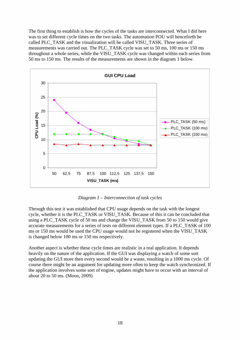
The first thing to establish is how the cycles of the tasks are interconnected. What I did here was to set different cycle times on the two tasks. The automation POU will henceforth be called PLC_TASK and the visualization will be called VISU_TASK. Three series of measurements was carried out. The PLC_TASK cycle was set to 50 ms, 100 ms or 150 ms throughout a whole series, while the VISU_TASK cycle was changed within each series from 50 ms to 150 ms. The results of the measurements are shown in the diagram 1 below.
GUI CPU Load
0
5
10
15
20
25
30
50 62,5 75 87,5 100 112,5 125 137,5 150
VISU_TASK (ms)
CP
U L
oad
(%
)
PLC_TASK (50 ms)
PLC_TASK (100 ms)
PLC_TASK (150 ms)
Diagram 1 – Interconnection of task cycles
Through this test it was established that CPU usage depends on the task with the longest cycle, whether it is the PLC_TASK or VISU_TASK. Because of this it can be concluded that using a PLC_TASK cycle of 50 ms and change the VISU_TASK from 50 to 150 would give accurate measurements for a series of tests on different element types. If a PLC_TASK of 100 ms or 150 ms would be used the CPU usage would not be registered when the VISU_TASK is changed below 100 ms or 150 ms respectively. Another aspect is whether these cycle times are realistic in a real application. It depends heavily on the nature of the application. If the GUI was displaying a watch of some sort updating the GUI more then every second would be a waste, resulting in a 1000 ms cycle. Of course there might be an argument for updating more often to keep the watch synchronized. If the application involves some sort of engine, updates might have to occur with an interval of about 20 to 50 ms. (Moon, 2009)

19
4.7.1 Element types After establishing appropriate cycle intervals the actual experiment could now be carried out. Two different tests were performed. Both were done by comparing the CPU load of three different kinds of elements. The elements are:
• Bitmap and arrow • Background bitmap and arrow • Custom element
The bitmap and arrow element is a basic bitmap element with a polygon, representing an arrow, connected to the PLC_TASK. The arrow is set up to rotate around its turning point, located on the blunt side of the arrow. The background bitmap and arrow makes use of the background bitmap option, described in section 4.1, placed on top of the background is the same arrow element as in the previous element. The last element used is an element developed with the custom element API. As described earlier a custom element is a collection of basic elements. The element used here, representing a round meter, has been constructed from a bitmap element, six labels representing a scale, an arrow element as described earlier and also a label which displays the current value of the PLC_TASK variable.
4.7.2 Visualization cycle measurements In the first test each series run with a PLC_TASK cycle of 50 ms and a VISU_TASK cycle going from 50 to 150 ms. Each series used one of the three element types, the VISU_TASK consisted of only one element. The results are shown below in diagram 2.
Element CPU Load
0
5
10
15
20
25
30
35
50 62,5 75 87,5 100 113 125 138 150
VISU_TASK (ms)
Ele
men
t C
PU
Lo
ad (
%)
Bitmap and Arrow
Background Bitmap andArrow
Custom Element

20
Diagram 2 – Visualization cycle measurements
4.7.3 Multiple elements measurements In this test both the PLC_TASK and the VISU_TASK was assigned a static value throughout the series. Instead the number of elements included in the VISU_TASK was used as the variable, increasing from one to six during the series. Six elements cover the whole screen of the CCP XS.
GUI CPU Load
0
10
20
30
40
50
60
70
80
90
100
1 2 3 4 5 6
Number of Elements
GU
I CP
U L
oad Bitmap and Arrow
Background Bitmap andArrow
Custom Element
Diagram 3 – Multiple elements measurements

21
5 Evaluation of CoDeSys V3 CoDeSys V3 is redeveloped from scratch. This made it possible to change fundamental aspects of how development with the tool is functioning. It offers object oriented development within POUs and libraries. The library handling is extended and the Library Manager has integrated documentation. When developing a library it can easily be compiled for distribution and included by customers. Another new feature is the ability to only update the part of the screen that is needed, thus reducing the time it takes to repaint a screen. This feature is something that has been presented to be included in CoDeSys V3 by 3S, but not explicitly tested in the paper. (Lodin, 2009b)
5.1 Development environment The development environment in CoDeSys V3 has a modular structure. The modules can be moved around and anchored as seen fit by the developer. In figure 3 the standard setup for development is show. The POUs view organizes the POUs, visualizations etc. in a tree structure. A project can have one or more device resources; these are organized in the device view. The editor view is where you design your code or visualization. The message window supplies information about compilation and error handling. The toolbox organizes the elements used to construct visualizations with. There are several sections for basic, windows and complex elements. Bellow the Toolbox is the element properties view where an elements property can be configured. Several elements can be configured simultaneously. Too keep track of all the images included in the project there are image pools. (Lodin, 2009b)
Figure 3 – The CoDeSys V3 development environment

22
5.2 Elements The element toolbox offers the same elements as in CoDeSys V2. There are some minor upgrades. You can for example include a Windows Metafile Format (WMF) file in the image element. The elements are grouped into different categories, basic, windows and complex controls. More tabs can be added with the custom element API. (CoDeSys V3)
5.3 Custom element API Custom element development is in CoDeSys V3 integrated in CoDeSys environment. An element is constructed by writing a library in IEC code. All elements implements the class IVisualElement which defines a standard structure for what functions an element need, class references can be found in appendix V. When the development of an element is finished it will be added to the toolbox through the Visual Element Repository which keeps track of all elements and their versions. It is possible to customize the name, icon and group of the element for the toolbox. (Lodin, 2009b) Construction is still done with the basic elements, as in CoDeSys V2, but the custom elements handle updates and can trigger events during runtime. For example if we design a slider element an update function would be called when the knob is moved. There is also a paint function included in the elements which allows us to be more specific with what we want to repaint. Being able to dynamically change our element makes it possible to create additional elements in our element during runtime. (Lodin, 2009b)

23
6 Comparison and results Let’s go back to the goals defined in section 3, platform goals, and apply these goals one by one on the facts brought up in the evaluations.
6.1 Support development of custom element This goal has four sub criteria but let us start with looking if custom elements are something that is supported at all by the platforms. As explained by Pfob (2002) and Lodin (2009b) there is possibilities for developing custom elements for both platforms. The initial observation is that the same basic elements are offered as building blocks in both versions of CoDeSys. When comparing the interfaces further to build an element in CoDeSys V2 a blueprint is designed. A blueprint for how to layout the components that forms an element. It is not a complete interface and the elements will be very static since it is not possible to interact with it other then by clicking it to tap or toggle a Boolean value during runtime. This is no the case in CoDeSys V3 where the components can raise events and be updated during runtime as well as repainted in any fashion seen fit. This makes it possible to create for example a slider component or determine when two elements collide. When it comes to the actual development of elements it is done in either C++, for CoDeSys V2, or IEC code, for CoDeSys V3. There is no better or worse here, a programmer being fluent in C++ but had no prior experience with IEC code would find the C++ API more intuitive and the other way around. What can be said is that the win32 API used to create the configuration dialogs for CoDeSys V2 is somewhat outdated compared to today’s standards. In CoDeSys V3 a configuration dialog is simply defined in the main file of the element class.
6.1.1 Integration in the platform Let us now look at the first of the properties desired to be supported from the custom elements API which is integration in the platform. Integration here means if the elements can be implemented to be a part of the natural toolbox in CoDeSys. The answer is yes, we can accomplish this on both platforms. In CoDeSys V2 we add an icon file and define a name for the element in its resource file. For CoDeSys V3 the name, icon and also group is defined in the main class of the element. Both platforms performs this task satisfactory, as mentioned CoDeSys V3 do offer to group your own components in its own group taking the customization a small step further.
6.1.2 Means to distribute and install Furthermore there is the goal to provide means to distribute and install the elements on a target developer’s machine. In CoDeSys V2 all elements are located in a DLL which have to be located in a subfolder of the CoDeSys installation. So in order to distribute and install the elements on a customer’s machine some kind of installation script would be needed. This could be done by an already existing script CC Systems provide for customizing CoDeSys for their products according to Andersson (2009b). The library management in CoDeSys V3 is extended compared to how it functions in CoDeSys V2. It is easy to browse and has an interface for showing documentation about the classes, function and input/output values of the library. This can be compared to CoDeSys V2 where a library simply is a collection of POUs. An element in CoDeSys V3 is written in a library, it is possible to have multiple elements in

24
the same library or use one library for each element. In order to distribute an element for CoDeSys V3 a library needs to be distributed. These libraries can be compiled and then distributed in the same manner as a DLL. When the library is distributed to the target system it is included in the toolbox through the Visual Element Repository. This was demonstrated by Lodin (2009b).
6.1.3 Simplicity and Adoptability The two last aspects of the elements are actual properties of the elements. Simplicity is asked for due to it being a sales argument and also to make it easier for the would-be developer. The adoptability is needed to satisfy the demands of different customers wanting unique GUIs. A custom element functions in the same way as any basic or advanced element in both CoDeSys V2 and V3. I would like to claim that both environments are built to provide simplicity. They provide a simple drag and drop interface, as opposed to a code-driven interface where the elements would be coded in an html fashion. The configuration is done by a dialog where all available options are presented to offer an overview of the possibilities. These abstractions are in line with what the laws of simplicity (http://lawsofsimplicity.com/) demands to provide simplicity. When creating a custom element how the developer chooses to design the choices in the configuration dialog as well as what choices the developer chooses to feature will make the adoptability and simplicity on an element level. There is possibility for both properties. It is up to the developer to emphasize on them by removing unnecessary dialog choices and still keep the customization of the element available.
6.2 Performance criteria What can be concluded from the performance tests and is shown very clear in both diagram 2 and diagram 3 is that by putting a bitmap in the background the CPU load is lowered significant. The other two elements do not differ much in CPU usage, even though the custom element is made up of more elements. When the element CPU load in the first test is examined it is clear that at low cycle times, such as 50 ms, the percentage tends to be too high for what is acceptable. As stated in the performance goal there is no hard limit for this, but when discussing the diagrams with Tobias Andersson (2009c) it was determined that this result was too high. This is shown even clearer in the second test where six meters would fully occupy the CPU. One possible solution for this problem is to better monitor what to repaint in the GUI, which has been presented to be a feature of CoDeSys V3.
6.3 Custom element development tool When developing components for CoDeSys V2 there is also the drawback of using Microsoft Visual Studio. Not that the tool in itself is bad, but it forces the use of two tools, both CoDeSys and Microsoft Visual Studio. Only using one tool can be a big advantage since more then one software results in more licenses costs and the developer will need to be familiar with more than one tool. In CoDeSys V3 the element development is integrated in the environment and is done in IEC code. A feature appreciated by Andersson (2009a).

25
6.4 Development environment The development environments have the same basic functionality, the POU and visualization organizers are there and the main edit window is very similar in the two versions. Still CoDeSys V3 have a fundamental difference in how it is built. The modularity gives the developer a more open and customizable environment, compared to the static layout in CoDeSys V2. The other major improvement, in CoDeSys V3, is how the element properties are configured. Instead of the modal configuration dialogs there is the element properties view which is always visible, easier to access since it is not modal and has the ability to configure multiple elements simultaneously. There is also the image pool too keep track of all the images you are using in your project. It is possible to name the images to project specific names to keep order of them easier. The environment feels, even more then before, like one tool.

26
7 Conclusion I can conclude that the platform goals set up for the evaluation has been met, apart from the performance criteria. In the case of CoDeSys V3 no test has been performed since there is no soft PLC to run on the CCP XS. For CoDeSys V2 test where performed and the results show that in order to build GUIs that are actually realizable all bitmaps need to be put in the background and the cycle time needs to be lower then what might be possible in order to show data in a real application. With that stated the interesting observation is not if goals have been met but how they have been met. It is possible to create custom elements for both platforms, the elements will be integrated in the environment, it is possible to distribute and install then on other machine. The elements can be designed to support simplicity and adoptability. These are facts, but what distinguishes the platforms from each other? Since CoDeSys V3 is redeveloped from scratch 3S has taken time to rethink some of the fundamental aspects of the platform. Introducing object orientation improves how both automation and element classes are constructed. It has made the custom element development more integrated in CoDeSys V3 since it is no longer an external interface next to the platform. This has also created a close connection between the custom elements and CoDeSys V3. It is possible to interact with the element while in online mode by firing events to the component which opens up for new ways to interact and control a GUI. The library management in CoDeSys V3 is easy to browse and has an interface for showing documentation about the classes, function and input/output values of the library. This can be compared to CoDeSys V2 where a library simply is a collection of POUs. The library management in combination with the integrated element development and the Visual Element Repository in CoDeSys V3 make the handling of elements a smooth process. In CoDeSys V3 everything comes together and makes CoDeSys act as one tool more then before. It keeps track of your images in the project with image pool, the library handling is improved to handle both automation, visualizations and the element development is done in ETC code and can be distributed as a CoDeSys library. On thing to keep in mind is that concepts CoDeSys have missed might also be left out in this evaluation. There are some aspects brought up in the limitations parts of the evaluation but there could be other platforms better suited for CC Systems needs. This however has been a comparison of the two CoDeSys platforms and with this intended focus overlooking other options was necessary.

27
8 Future work There are a few things I could not accomplish due to technical reasons or due to me not having enough experience and information to make proper judgement about the issue. First there is the performance test for the CoDeSys V3 platform which was not concluded. It can be done on a PC, but this would not give a fair view of the platforms performance. Another aspect left out is how mature the V3 platform is. It is hard to elaborate on this issue since any real test can not be carried out before the platform is ported to CC Systems products. Some indications on the state of the platform can be achieved by looking on the bug reports found on 3S-Softwares website, (http://www.3s-software.com). About 900 bugs have been reported on the CoDeSys V3 platform during 2009, until 5th of June, the same amount as 2008 during the same period. It was brought up during the source discussion that the documentation of CoDeSys V3 is inadequate especially when it comes to the custom element API. In order to utilize the possibilities within the platform some kind of documentation off the API is needed. Not only for how an element is designed, this can be apprehended relatively easy, but how the underlying structure with events and such works. Furthermore an investigation on how GUIs for machines and vehicles should be constructed could be interesting to CC Systems. Questions like how GUIs should be built to optimize usability have not been covered at all in this report. When discussing GUIs with some employees at CC Systems several aspects has come up such as options to offer a high contrast view for when working in daylight. There has been a lot of research done on the area of usability and how operation of control system is done. A good place to start could be Automation and Human Performance (Endsley, M.R., 1996) or Usability Design: A Framework for Designing Usable Interactive Systems in Practice by Göransson (2001). The CCP XS is a very complex display unit, how could the touch screen be used to a wider extent then it is today. During this evaluation the argument for having graphically advanced GUIs since it will sell the product has been brought up several times. How does the selling point of a GUI correspond to what the end user wants of the GUI? These are questions not asked or answered in this paper which CC System could benefit from looking into.

28
9 References
9.1 Bibliography Cronholm, Stefan & Goldkuhl, Göran (2003), Strategies for Information Systems Evaluation
– Six Generic Types, Electronic Journal of Information Systems Evaluation, vol. 6: 2, ss. 65-74. Also available at http://www.ejise.com/volume6-issue2/issue2-art8-cronholm.pdf
Endsley, M.R.: Automation and situation awareness. In R. Parasuraman & M. Mouloua (Eds), Automation and Human performance: Theory and applications (Oxford : Taylor & Francis, Inc, 1996)
Göransson, Bengt: Usability Design: A Framework for Designing Usable Interactive Systems In Practice (Uppsala: Department of Informations Technology, Uppsala Universistet, 2001)
Hoepfl, Marie C (1997), Choosing Qualitative Reasearch: A Primer for Technology Education Researchers, Journal of Technological Education, vol 9: 1. Also available at http://scholar.lib.vt.edu/ejournals/JTE/v9n1/hoepfl.html
Patton, M. Q: Qualitative Evaluation and Research Methods (2nd ed.). (Newbury Park, CA: Sage Publications, Inc, 1990)
9.2 Other printed references 3S-Software, User Manual for PLC Programming with CoDeSys 2.3, user manual (Uppsala :
3S-Software, 2007)
3S-Software, CoDeSys Visualization, user manual (Uppsala : 3S-Software, 2008)
CC Systems, Beskrivning av examanesarbete – Graphical interface framework for control
system environments, document (Uppsala : CC Systems, 2009) CC Systems, CrossTalk, information leaflet (Uppsala : CC Systems, 2007). Also available at http://www.cc-systems.com/Portals/0/PDF/Products/Leaflet/CrossTalk2007.pdf CC Systems, CC Pilot XS, information leaflet (Uppsala : CC Systems, 2008). Also available
at http://www.ccsystems.com/Portals/0/PDF/Products/Leaflet/CCPilotXSAll-Integrated-Adress.pdf
Pfob, Michael, Plugin Interface for the CoDeSys Visualisation, user manual (Uppsala: CC Systems, 2002)
9.3 Electronic references CC Systems website http://www.cc-systems.com, retrieved 2009-05-06

29
3S-Softwares website http://www.3s-software.com, retrieved 2009-05-06 The laws of simplicity
http://lawsofsimplicity.com/, retrieved 2009-05-06
Qt-software http://www.qtsoftware.com/, retrieved 2009-06-05
CoDeSys V3, Online Help Documentation, retrieved 2009-05-05 Wikipedia 2009, article about IEC 61131-3 http://en.wikipedia.org/wiki/IEC_61131-1, retrieved 2009-02-04
9.4 Oral and email communication Andersson, Tobias (a), Software developer at CC Systems, Uppsala 2009-02-27 Andersson, Tobias (b), Software developer at CC Systems, Uppsala 2009-03-05 Bäckström, Johan, Software developer at CC Systems, Uppsala 2009-03-04 Gustafsson, Lars, Software developer at CC Systems, Uppsala 2009-03-04 Lans, Fredrik, Software development manager at CC Systems, Uppsala 2009-02-27 Lodin, Lars (a), CoDeSys Expert at Best Engineering Scandinavia, Järvsö 2009-02-11 Lodin, Lars (b), CoDeSys Expert at Best Engineering Scandinavia, Järvsö 2009-05-05 Moon, Carl-Magnus, Software developer at CC Systems, Uppsala 2009-04-05 Pfob, Michael, Software developer at 3S-Software, Kempten 2009-03-02 Wahlström, Fredrik, Software developer at CC Systems, Uppsala 2009-03-09 Wendebaum, Jochen, Software developer at CC Systems, Västerås 2009-04-07

30
10 Appendix
10.1 Appendix I: Dictionary API Application Programming Interface, a set of data structures and object
classes provided to support building of applications CoDeSys Controller Development System, a PLC development platform developed
by 3S-Software. CoDeSys Visu Controller Development System Visualization, the visualization editor of
CoDeSys, used to create GUIs with. GUI Graphical User Interface, an user interface that allows a user to interact
with electronic devices. PLC Programmable Logic Controller, a digital computer used for automation
of industrial processes. POU Program Organization Unit, a code file used in CoDeSys V2 and
CoDeSys V3. IEC International Electrotechnical Commission, an international standards
organization dealing with electrical, electronic and related technologies IEC 61131-3 A programming language standard developed by the International
Electrotechnical Commission Visualization Another term for a GUI, frequently used in CoDeSys documentation.
10.2 Appendix II: Custom element communication with CoDeSys The interface of the DLL is called by CoDeSys for information about the custom elements and needs to be named *.ete. The interface consists of the following functions:
int GetElementsCount ();
Returns the number of available control elements
const char* GetElementName (int iElemNr);
Returns the name of the control element with the number iElemNr
WORD GetElementIcon(int iElemNr);
Returns the IconID of the control element with the number iElemNr
XMLTagNode* CreateElement(int iElemNr, XMLTagNode* pXMLRoot, HWND hParent, void (*SubClassEdit)(HWND));
Generates the dialogue for the generation of a new control element with the number iElemNr out of the transferred XML tree pXMLRoot. hParent is the handle of the window which

31
possesses the dialogue. SubClassEdit is a pointer to the function which permits access to the already declared variables via Intellisense. If this function is called in a dialogue (e.g. during WM_INITDIALOG) with the handle of an edit control then this edit determines controls the Intellisense function of CoDeSys. The XML tree of the generated control element is returned. In case the dialogue is cancelled with ‘Cancel’ a ZERO will be returned.
void DeleteXMLTree (XMLTagNode* pXMLRoot);
Releases the XML tree generated by CreateElement. This routine is necessary. Otherwise there may be problems if memory in the executable which was reserved in the DLL is released.
10.3 Appendix III: Element IDs for custom elements The range of possible custom elements starts by 46040 and ends by 46065. Up to 25 different element types can be created. The IDs of the elements which may generate a DLL must be consecutively numbered beginning with 0 up to the total number of possible elements minus 1. Here follows an example of how a “test element” is defined:
10.3.1 Resource.h #define IDM_INSERTTESTELEM 46040 #define IDS_NAME_TESTELEM 46140 #define IDI_TESTELEM 46040
10.3.2 globals.h #define ELEMCOUNT 1 #define TESTELEMID 0
10.3.3 ElementDLL.cpp ELEMENTDLL_API int GetElementsCount(void) { return ELEMCOUNT; } ELEMENTDLL_API WORD GetElementId (int iNr) { switch (iNr) { case TESTELEMID: { return IDM_INSERTTESTELEM; }
/* + 100 means, that name of the element is requested so the resource ID of the string is returned */
case TESTELEMID + 100: {
return IDS_NAME_TESTELEM; }
/* + 200 means, that cursor of the element is requested so the resource ID of the cursor is returned. */
case TESTELEMID + 200:

32
{ return IDC_CUR_TESTELEM;
} /* + 300 means, that icon of the element is requested so the resource ID of the icon is returned */
case TESTELEMID + 300: {
return IDI_TESTELEM; } default: { return 0; } } }
10.4 Appendix IV: VisualElem Class References Public Member Functions virtual XMLTagNode * GetXMLNode ()
virtual void SetFrameColor (COLORREF col)
virtual void SetInsideColor (COLORREF col)
virtual void SetFrameColorAlarm (COLORREF col)
virtual void SetInsideColorArarm (COLORREF col)
virtual void SetHasFrameColor (bool val)
virtual void SetHasInsideColor (bool val)
virtual void SetLineWidth (int width)
virtual void SetExprXOffset (string expr)
virtual void SetExprYOffset (string expr)
virtual void SetExprScale (string expr)
virtual void SetExprAngle (string expr)
virtual void SetExprInvisible (string expr)
virtual void SetExprAlarm (string expr)
virtual void SetCenter (Point center)
virtual void SetToggleVariable (string var)
virtual void SetZoomVisu (string var)
virtual void SetExec (string var)
virtual void SetTapVariable (string var)
virtual void SetCalculatedCenter ()=0
virtual COLORREF GetFrameColor () virtual COLORREF GetInsideColor () virtual COLORREF GetFrameColorAlarm ()
virtual COLORREF GetInsideColorArarm ()
virtual int GetLineWidth ()
virtual string GetExprXOffset () virtual string GetExprYOffset () virtual string GetExprScale ()

33
Protected Member Functions
VisualElem (const VisualElem &VElem)
virtual void PaintText (HWND hwnd, HDC hdc, RECT rect, Point OutTopLeft, Point OutBottomRight, int iSizeX, int iSizeY)
XMLTagNode * GetExprNode (const string &strMainTag, const string &strVar, bool isVar=true)
Protected Attributes bool m_bHasFrameColor bool m_bHasInsideColor
COLORREF m_FrameColor COLORREF m_InsideColor COLORREF m_FrameColorAlarm
virtual string GetExprAngle ()
virtual string GetExprInvisible ()
virtual string GetExprAlarm ()
virtual Point GetCenter () virtual string GetToggleVariable ()
virtual string GetZoomVisu ()
virtual string GetExec ()
virtual string GetTapVariable ()
virtual bool HasFrameColor () virtual bool HasInsideColor ()
virtual int GetFontSize ()
virtual string GetHorzAlignment () virtual string GetVertAlignment ()
virtual void SetItalic (BOOL val)
virtual void SetStrikedOut (BOOL val)
virtual void SetUnderlined (BOOL val)
virtual void SetFontWeight (int weight)
virtual void SetCharSet (unsigned char charset)
virtual void SetFontColor (COLORREF col)
virtual void SetAlignHorz (HorzAlignment horz)
virtual void SetAlignVert (VertAlignment vert)
virtual void SetFontSize (int size)
virtual void SetLabelText (string text)
virtual void SetFontName (string name)
virtual void SetTextVariable (string var)
virtual void SetFont (const CHOOSEFONT &chFont)
virtual BOOL CalculateTextSize (SIZE *sz)
virtual void PaintElement (HWND hwnd, HDC hdc, RECT rect, int iSizeX, int iSizeY)=0

34
COLORREF m_InsideColorAlarm int m_iLineWidth
string m_strExprXOffset string m_strExprYOffset string m_strExprScale string m_strExprAngle string m_strExprInvisible string m_strExprAlarm string m_strToggleVariable string m_strZoomVisu string m_strExec string m_strTapVariable Point m_CenterPoint
HorzAlignment m_iAlignHorz VertAlignment m_iAlignVert
CHOOSEFONT m_ChooseFont LOGFONT m_LogFont
string m_strText string m_strTextVariable
10.5 Appendix V: IVisualElement Interface References
BOOL ContainPoint (VisuStructPoint pt)
BOOL Destruct ()
INT ElementInfo (POINTER TO Visu_StructElementInfo pData)
POINTER TO VisuStructClientData
GetClientData ()
POINTER TO BYTE GetClientSpecificData (POINTER TO STRING pst)
VisuStructSimpleRectangle GetSurroundingRect ()
BOOL
GetTextProperties (POINTER TO VisuStructFont pFont, POINTER TO DWORD pOptAlignment, POINTER TO STRING pText, POINTER TO POINTER TO STRING ppTooltip, POINTER TO DWORD pFlags)
BOOL GetUpdateRects (INT elemIndex)
BOOL HandleInput (POINTER TO VisuStructEvent pEvent)
BOOL Initialize (IVisualization parentVisu)
BOOL Point (POINTER TO VisuTbCommandBuffer pPaintBuffer, BOOL pStatic, BOOL bDynamic)
BOOL SetClientData (POINTER TO VisuStructClientData pClientData)
BOOL SetStaticState ()
BOOL Update ()
IVisualElement Interface References