Embed Size (px)
Citation preview
Hydraulic Calculations
Objectives
• We will cover the following:– The basic formulas for calculating:
• Determining pump discharge pressure• Determining flow• Calculating friction loss•

It’s about the math
• Yep it’s algebra, get over it
• This is why your Mom and Dad told you to pay attention in school
• I know most of you haven’t done math since you left school
• I was worse at math than you

Too much time
• Most guys will spend MOST of their time preparing for the Drivers test studying the math
• Realistically it’s less than 30% of the test
• It’s the most important 30% but still it’s only 30%
This is just a review
• This is not an algebra course, we don’t have the time for that
• It’s just a review of the formulas and a chance for us to make sure you are working them correctly
Pump Discharge Pressure
• Pump discharge pressure is the SUM total of ALL losses– Friction loss– Nozzle pressure– Elevation loss– Appliance loss
• Formula – PDP=NP+FL+EL+AL
LET’S START WITH FRICTION LOSS
Friction Loss
• Standard Calculation:– CQ2L
• C=Coefficient (from chart)
• Q=Flow (gpm/100)
• L=Length (figured in 100 foot lengths)
Coefficients – (C)
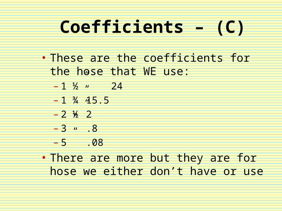
• These are the coefficients for the hose that WE use:– 1 ½” 24– 1 ¾” 15.5– 2 ½” 2– 3” .8– 5” .08
• There are more but they are for hose we either don’t have or use
How to determine flow – (Q)
• There are three possibilities when it comes to Q:– Smooth bore nozzles have to be
calculated based on tip size– Selectable gallon nozzles are determined
by the selected flow– Automatic nozzles are determined
desired flow
Calculating flow
• Smooth bore formula:– 29.7 X D2 X √np– 29.7 is a constant
– D2 is the nozzle tip size squared– Square root of the nozzle pressure
• Hand lines – 7• Master streams - 9
The constant
•29.7
Diameter squared
• 1” tip– d=1, d2= 1 x 1 or 1
• 1 ½” tip– d=1.5, d2= 1.5 x 1.5 or 2.25
• 2” tip– d=2, d2= 2 x 2 or 4
• The principle is the same for ANY smooth bore orifice regardless of size
Square root of NP
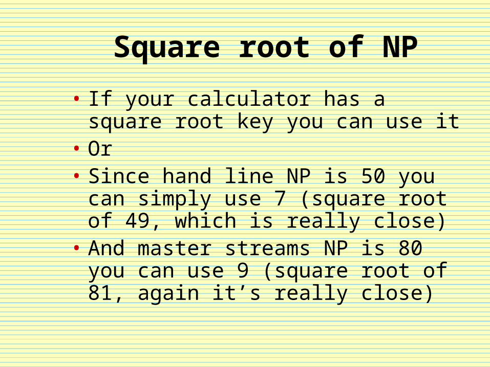
• If your calculator has a square root key you can use it
• Or• Since hand line NP is 50 you can
simply use 7 (square root of 49, which is really close)
• And master streams NP is 80 you can use 9 (square root of 81, again it’s really close)
Example for finding (Q)
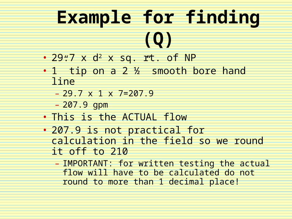
• 29.7 x d2 x sq. rt. of NP• 1” tip on a 2 ½” smooth bore hand line
– 29.7 x 1 x 7=207.9– 207.9 gpm
• This is the ACTUAL flow • 207.9 is not practical for calculation in the
field so we round it off to 210– IMPORTANT: for written testing the actual flow
will have to be calculated do not round to more than 1 decimal place!
Rounded field flow
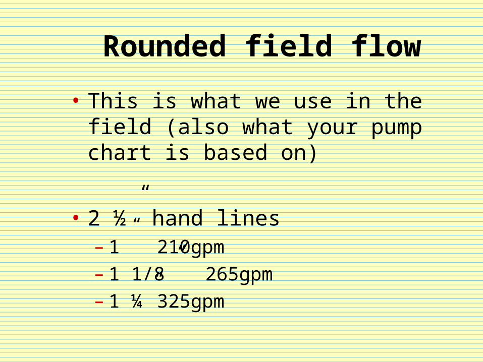
• This is what we use in the field (also what your pump chart is based on)
• 2 ½” hand lines– 1” 210gpm– 1 1/8”265gpm– 1 ¼” 325gpm
Calculated and field flows
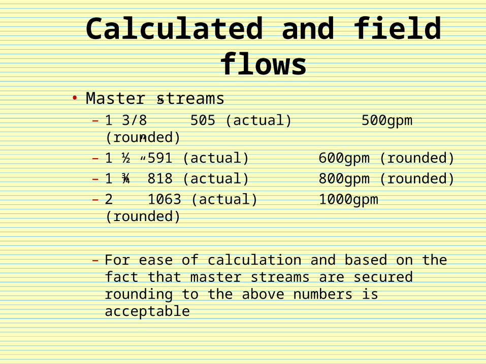
• Master streams– 1 3/8” 505 (actual) 500gpm (rounded)– 1 ½” 591 (actual) 600gpm (rounded)– 1 ¾” 818 (actual) 800gpm (rounded)– 2” 1063 (actual) 1000gpm (rounded)
– For ease of calculation and based on the fact that master streams are secured rounding to the above numbers is acceptable
Known Flow (Q)
• For known flows from selectable gallonage nozzles
• For automatic nozzles where you set the DESIRED gallonage
• Example:– 1 ¾” nozzle SET at 125gpm– Automatic nozzle where 125gpm is
desired
Determining Q
• Q simply stands for quantity
• In order to get Q to fit in the equation we have to work a formula to get a small number
• Otherwise we would have a large number that is unwieldy
• We simply divide GPM by 100 and then square the result
It’s really simple
• Q=GPM/1002
• 125gpm/1002
• 125/100=1.25• 1.25x1.25=1.56 (rounded to 2 decimal places)
• Q=1.56
Length – (L)
• This is the multiplier for your calculation of friction loss
• Since all calculations are figured on 100 foot sections we need to have a way to distribute your work to the entire system
• Each 100’ section gets a value of 1
• Example: 200’ of hose = 2
Putting it together
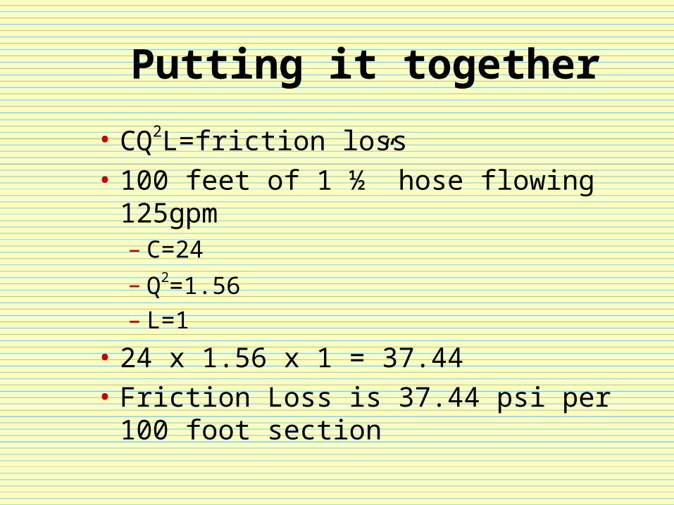
• CQ2L=friction loss
• 100 feet of 1 ½” hose flowing 125gpm– C=24
– Q2=1.56– L=1
• 24 x 1.56 x 1 = 37.44
• Friction Loss is 37.44 psi per 100 foot section
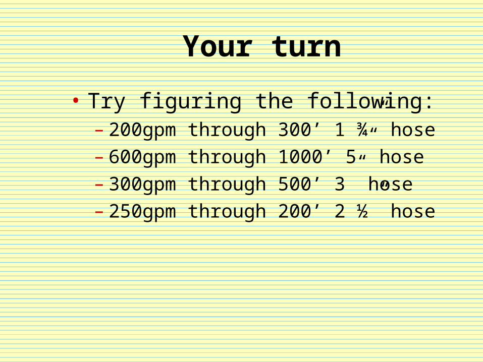
Your turn
• Try figuring the following:– 200gpm through 300’ 1 ¾” hose– 600gpm through 1000’ 5” hose– 300gpm through 500’ 3” hose– 250gpm through 200’ 2 ½” hose
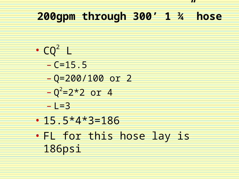
200gpm through 300’ 1 ¾” hose
• CQ2 L– C=15.5– Q=200/100 or 2
– Q2=2*2 or 4– L=3
• 15.5*4*3=186
• FL for this hose lay is 186psi
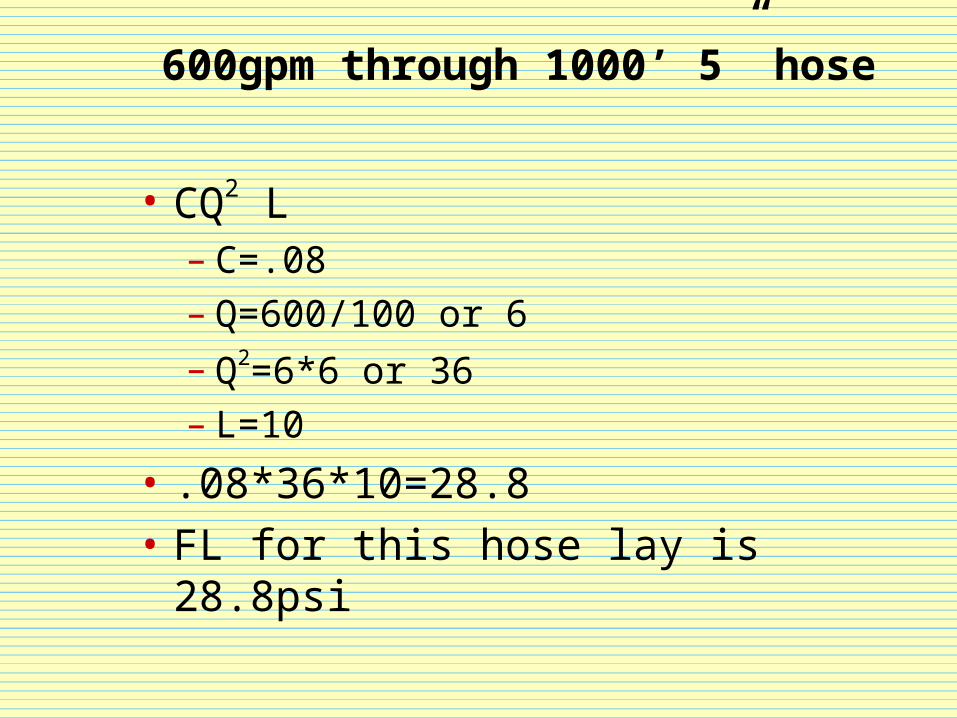
600gpm through 1000’ 5” hose
• CQ2 L– C=.08– Q=600/100 or 6
– Q2=6*6 or 36– L=10
• .08*36*10=28.8
• FL for this hose lay is 28.8psi
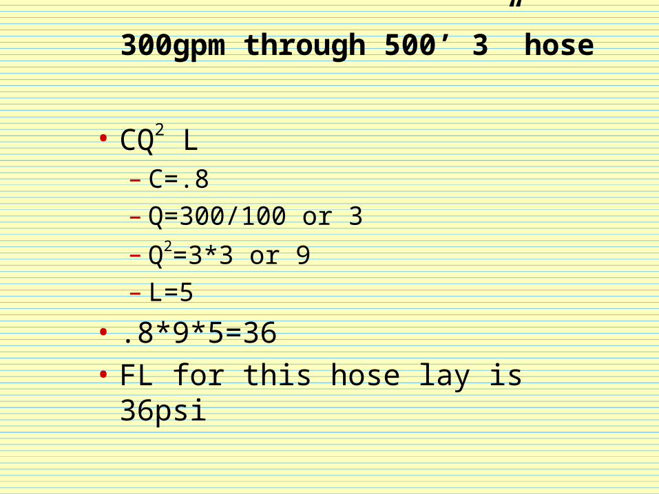
300gpm through 500’ 3” hose
• CQ2 L– C=.8– Q=300/100 or 3
– Q2=3*3 or 9– L=5
• .8*9*5=36
• FL for this hose lay is 36psi
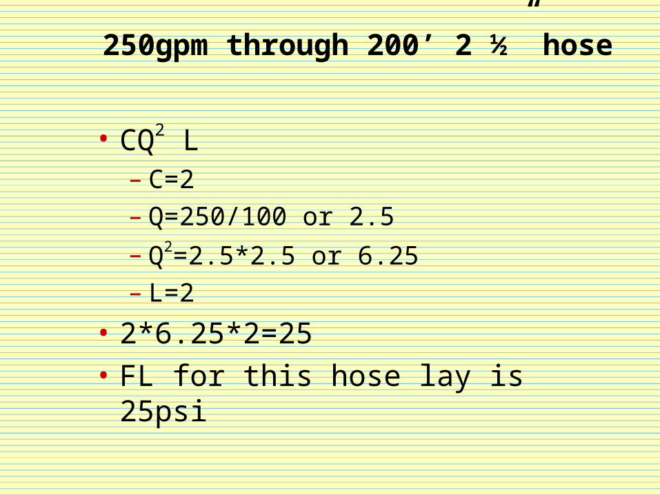
250gpm through 200’ 2 ½” hose
• CQ2 L– C=2– Q=250/100 or 2.5
– Q2=2.5*2.5 or 6.25– L=2
• 2*6.25*2=25
• FL for this hose lay is 25psi

NOW LET’S ADD THE NOZZLES
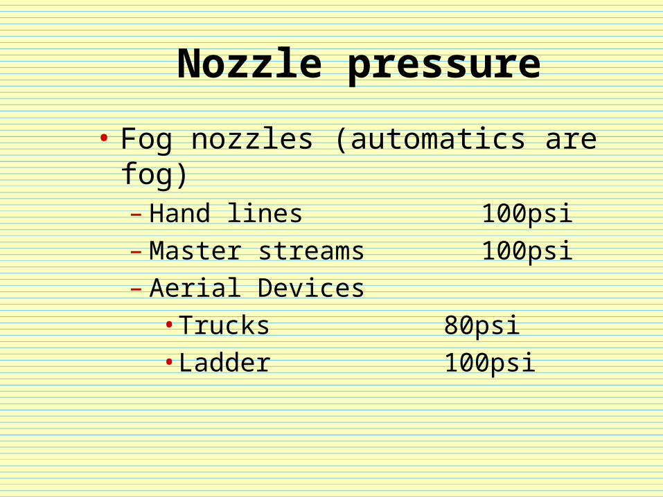
Nozzle pressure
• Fog nozzles (automatics are fog)– Hand lines 100psi– Master streams 100psi– Aerial Devices
• Trucks 80psi• Ladder 100psi
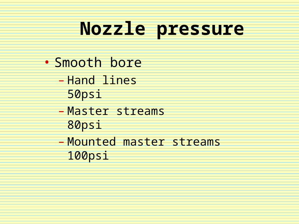
Nozzle pressure
• Smooth bore– Hand lines 50psi– Master streams 80psi– Mounted master streams 100psi

ELEVATION IS NEXT
Elevation Loss/Gain
• A column of water 1 foot tall exerts .434psi at it’s base
• We round this up to .5psi or ½ pound per foot
• This pressure works either for us or against us
Elevation Gain (head pressure)
• If we stay with the ½ pound per foot then we gain 5 pounds of force for every 10 feet
• 10*.5=5
• Example – A 100 foot water tower generates 50psi head pressure at its base
Elevation Loss
• If we have to move water up, the pressure is reversed
• Elevation loss is ½ pound per foot• 100 feet of elevation = 50psi of loss
Buildings and EL
• It’s just a little different, and really only applies to standpipes
• Floor height is considered to be 10 feet• Multiply 10 feet by .5 and the result is 5• Standard elevation loss is 5psi per floor
(not including the first floor)
AND FINISH WITH APPLIANCES
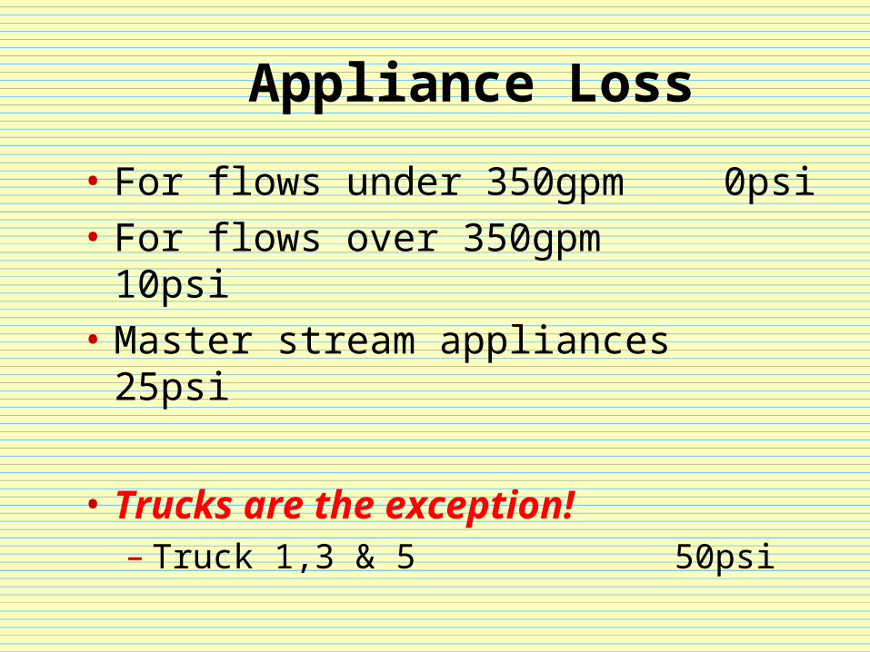
Appliance Loss
• For flows under 350gpm 0psi
• For flows over 350gpm 10psi
• Master stream appliances 25psi
• Trucks are the exception!– Truck 1,3 & 5 50psi
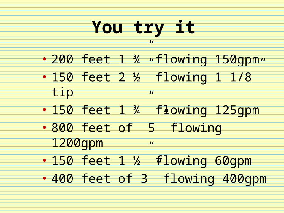
You try it
• 200 feet 1 ¾” flowing 150gpm
• 150 feet 2 ½” flowing 1 1/8” tip
• 150 feet 1 ¾” flowing 125gpm
• 800 feet of 5” flowing 1200gpm
• 150 feet 1 ½” flowing 60gpm
• 400 feet of 3” flowing 400gpm
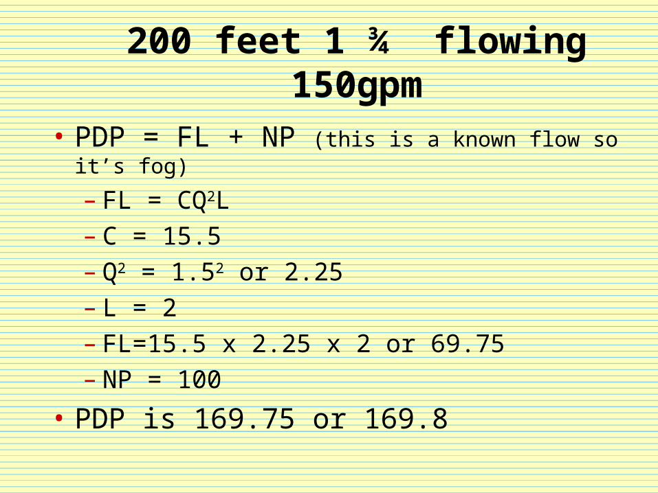
200 feet 1 ¾” flowing 150gpm
• PDP = FL + NP (this is a known flow so it’s fog)
– FL = CQ2L– C = 15.5– Q2 = 1.52 or 2.25– L = 2– FL=15.5 x 2.25 x 2 or 69.75– NP = 100
• PDP is 169.75 or 169.8
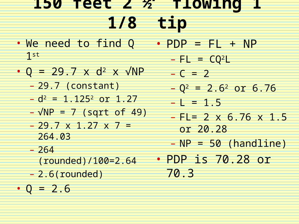
150 feet 2 ½” flowing 1 1/8” tip
• We need to find Q 1st • Q = 29.7 x d2 x √NP
– 29.7 (constant)– d2 = 1.1252 or 1.27– √NP = 7 (sqrt of 49)– 29.7 x 1.27 x 7 = 264.03– 264 (rounded)/100=2.64– 2.6(rounded)
• Q = 2.6
• PDP = FL + NP– FL = CQ2L– C = 2– Q2 = 2.62 or 6.76– L = 1.5– FL= 2 x 6.76 x 1.5 or
20.28– NP = 50 (handline)
• PDP is 70.28 or 70.3
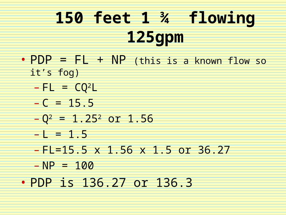
150 feet 1 ¾” flowing 125gpm
• PDP = FL + NP (this is a known flow so it’s fog)
– FL = CQ2L– C = 15.5– Q2 = 1.252 or 1.56– L = 1.5– FL=15.5 x 1.56 x 1.5 or 36.27– NP = 100
• PDP is 136.27 or 136.3
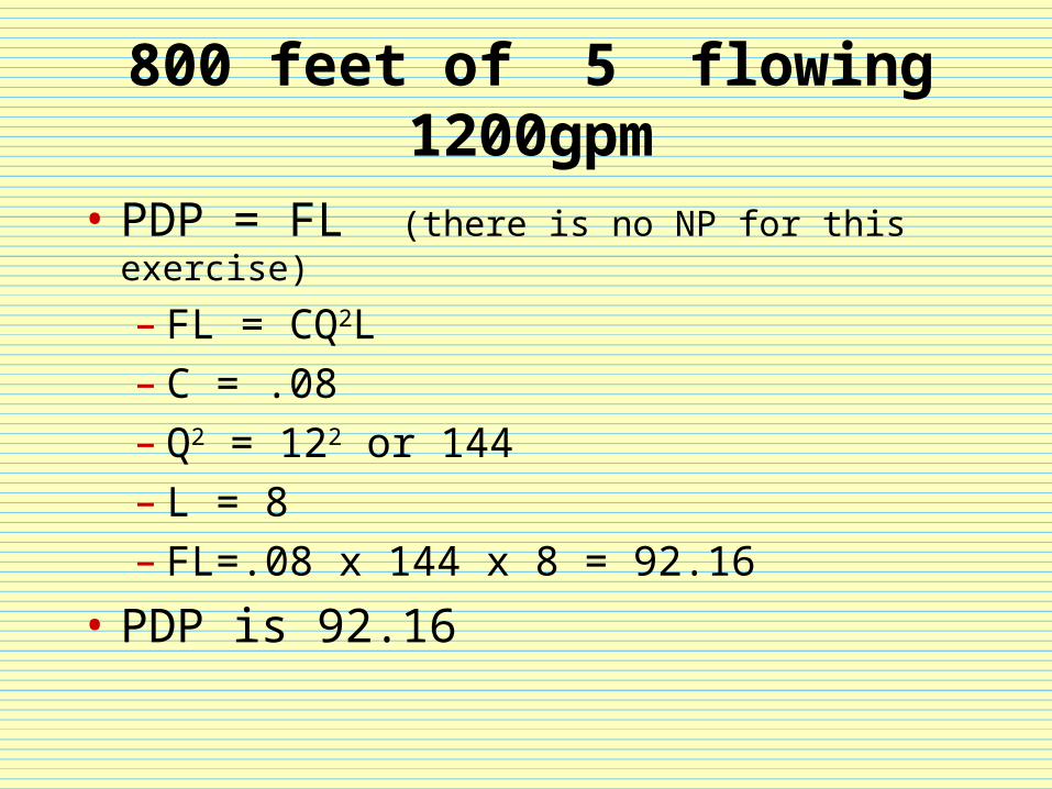
800 feet of 5” flowing 1200gpm
• PDP = FL (there is no NP for this exercise)
– FL = CQ2L– C = .08– Q2 = 122 or 144– L = 8– FL=.08 x 144 x 8 = 92.16
• PDP is 92.16
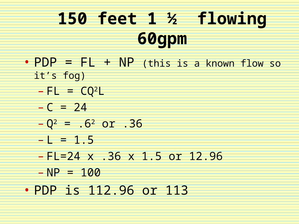
150 feet 1 ½” flowing 60gpm
• PDP = FL + NP (this is a known flow so it’s fog)
– FL = CQ2L– C = 24– Q2 = .62 or .36– L = 1.5– FL=24 x .36 x 1.5 or 12.96– NP = 100
• PDP is 112.96 or 113
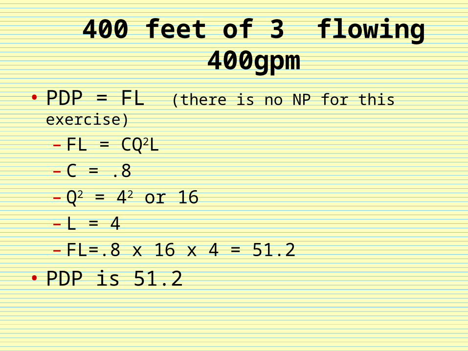
400 feet of 3” flowing 400gpm
• PDP = FL (there is no NP for this exercise)
– FL = CQ2L– C = .8– Q2 = 42 or 16– L = 4– FL=.8 x 16 x 4 = 51.2
• PDP is 51.2
COMPLEX HOSE LAYS
Complex hose lays
• Complex hose lays are nothing more than a series of simple lays strung together
• Complex lays are either wyed apart (flow is combined) or siamesed together (flow is divided)
• Major concern with multiple lines is length, diameter and flow per line
Pressure is the killer
• The reason we end up with complex lays is because of pressure
• High GPM flows generally equal high pressure
• The only way we reduce pressure is to reduce flow per line
• The way we do that is by adding lines to divide the flow
Two things
• The two factors we need to address are:– Maximum efficient flow– Percent of test pressure
Maximum efficient flow
• While it is theoretically possible to flow water forever there are real limits to how far we can shove water and still have a usable stream
• This is referred to as Maximum Efficient Flow (MEF)
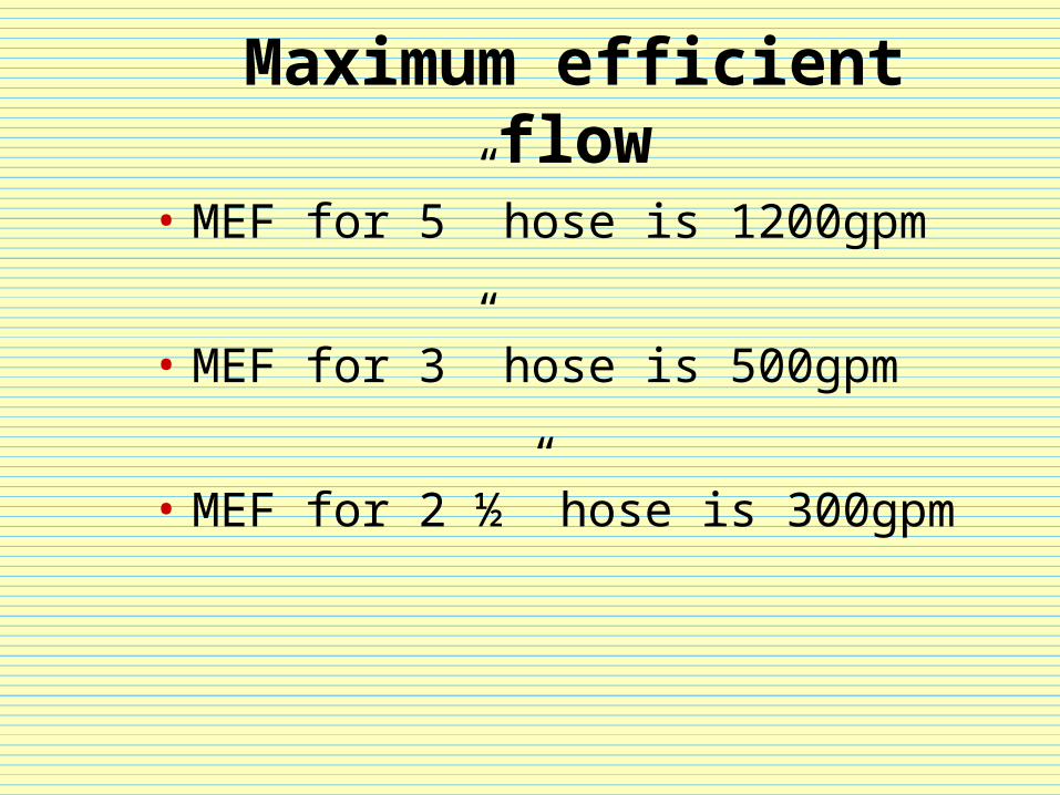
Maximum efficient flow
• MEF for 5” hose is 1200gpm
• MEF for 3” hose is 500gpm
• MEF for 2 ½” hose is 300gpm
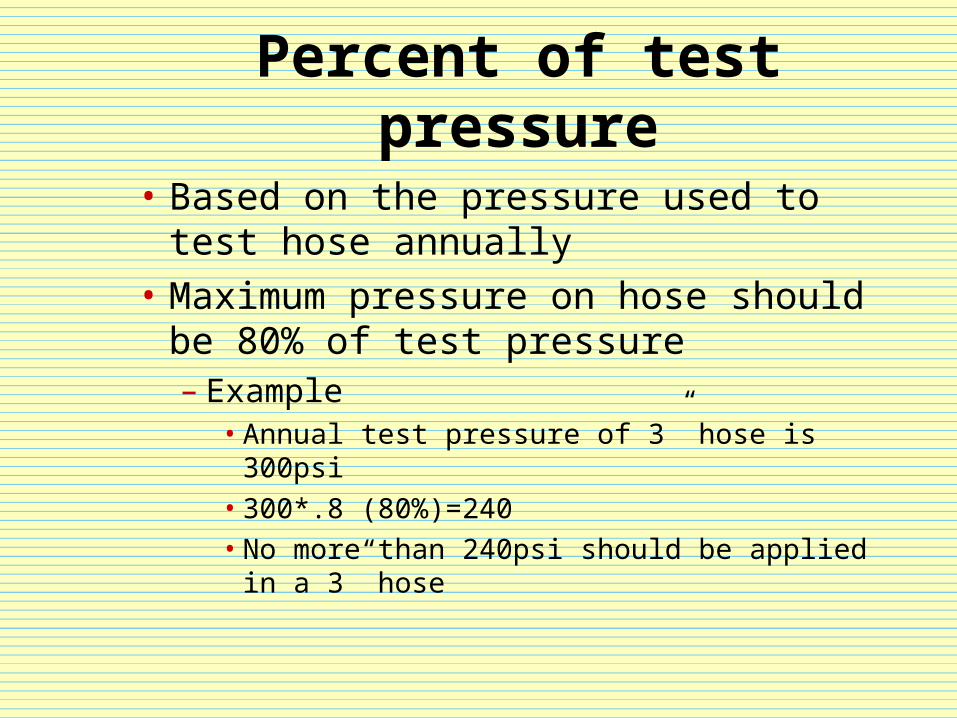
Percent of test pressure
• Based on the pressure used to test hose annually
• Maximum pressure on hose should be 80% of test pressure– Example
• Annual test pressure of 3” hose is 300psi• 300*.8 (80%)=240• No more than 240psi should be applied in a 3”
hose
So how do we reduce
• By either splitting the flow into additional same size lines or increasing the line size
Multiple supply/siamesed lines
• Multiple lines that supply a device (truck, standpipe, sprinkler etc.) that a single line would not be capable of supplying by itself
• Example – A portable monitor flowing 800gpm would
require at least dual 3” lines because of MEF.– The flow is divided equally between the 3” lines. – Friction loss is calculated based on a single 3”
line flowing 400gpm
Wyed lines
• Primarily lines are wyed when friction loss is a concern due to distance or elevation
• Example– Laying an 1 ¾” attack line that is 400’ long and going up 6
floors trying to flow 200gpm requires 378psi of pressure.– This exceeds the % of test pressure we are in danger of
bursting the line– By replacing 300’ of the lay with 2 ½” and then wying off
on the fire floor we now only need 216psi pressure, which is under the % of test pressure for the lines

YOUR TURN
PDP Examples
• 300 feet dual 3” hose with a total flow of 600gpm
• 1000 feet triple 3” hose with a total flow 1000gpm
• 300 feet 2 ½” hose wyed into two 1 ¾” lines each 100 feet flowing 125gpm
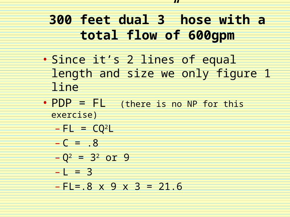
300 feet dual 3” hose with a total flow of 600gpm
• Since it’s 2 lines of equal length and size we only figure 1 line
• PDP = FL (there is no NP for this exercise)
– FL = CQ2L– C = .8– Q2 = 32 or 9– L = 3– FL=.8 x 9 x 3 = 21.6
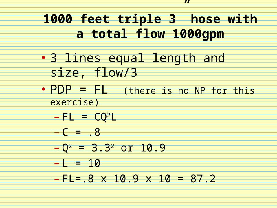
1000 feet triple 3” hose with a total flow 1000gpm
• 3 lines equal length and size, flow/3• PDP = FL (there is no NP for this exercise)
– FL = CQ2L– C = .8– Q2 = 3.32 or 10.9– L = 10– FL=.8 x 10.9 x 10 = 87.2
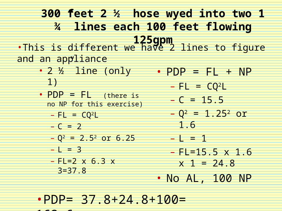
300 feet 2 ½” hose wyed into two 1 ¾” lines each 100 feet flowing 125gpm
• 2 ½” line (only 1)• PDP = FL (there is no
NP for this exercise)
– FL = CQ2L– C = 2– Q2 = 2.52 or 6.25– L = 3– FL=2 x 6.3 x 3=37.8
• PDP = FL + NP– FL = CQ2L– C = 15.5– Q2 = 1.252 or 1.6– L = 1– FL=15.5 x 1.6 x 1 =
24.8
• No AL, 100 NP
•This is different we have 2 lines to figure and an appliance
•PDP= 37.8+24.8+100= 162.6
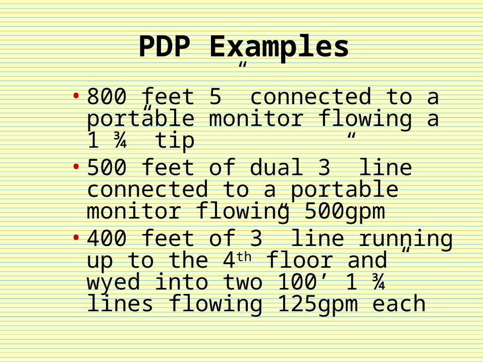
PDP Examples
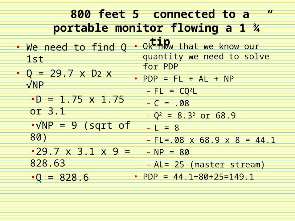
• 800 feet 5” connected to a portable monitor flowing a 1 ¾” tip
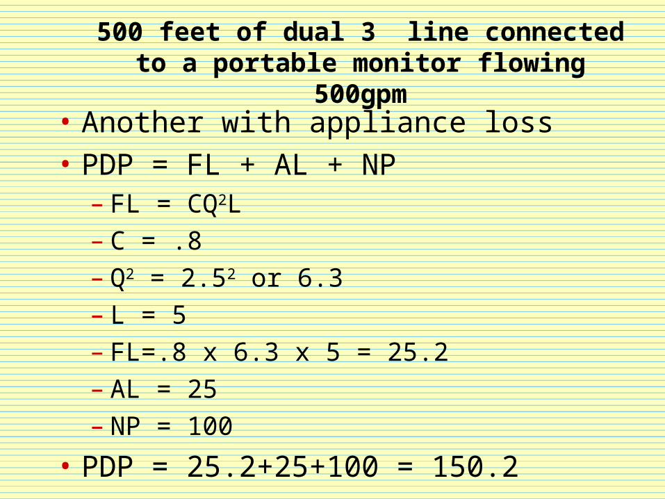
• 500 feet of dual 3” line connected to a portable monitor flowing 500gpm
• 400 feet of 3” line running up to the 4th floor and wyed into two 100’ 1 ¾” lines flowing 125gpm each
800 feet 5” connected to a portable monitor flowing a 1 ¾” tip
• Ok now that we know our quantity we need to solve for PDP
• PDP = FL + AL + NP– FL = CQ2L– C = .08– Q2 = 8.32 or 68.9– L = 8– FL=.08 x 68.9 x 8 = 44.1– NP = 80– AL= 25 (master stream)
• PDP = 44.1+80+25=149.1
• We need to find Q 1st • Q = 29.7 x D2 x √NP
•D = 1.75 x 1.75 or 3.1•√NP = 9 (sqrt of 80)•29.7 x 3.1 x 9 = 828.63•Q = 828.6
500 feet of dual 3” line connected to a portable monitor flowing 500gpm
• Another with appliance loss
• PDP = FL + AL + NP– FL = CQ2L– C = .8– Q2 = 2.52 or 6.3– L = 5– FL=.8 x 6.3 x 5 = 25.2– AL = 25– NP = 100
• PDP = 25.2+25+100 = 150.2
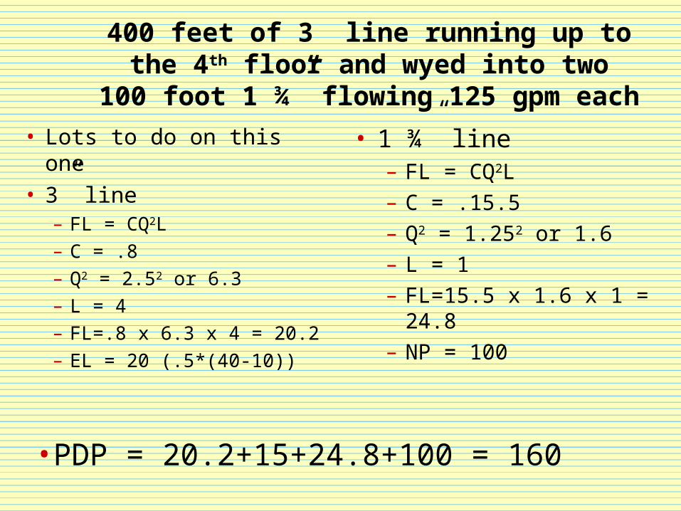
400 feet of 3” line running up to the 4th floor and wyed into two 100 foot 1 ¾”
flowing 125 gpm each
• Lots to do on this one• 3” line
– FL = CQ2L– C = .8– Q2 = 2.52 or 6.3– L = 4– FL=.8 x 6.3 x 4 = 20.2– EL = 20 (.5*(40-10))
• 1 ¾” line– FL = CQ2L– C = .15.5– Q2 = 1.252 or 1.6– L = 1– FL=15.5 x 1.6 x 1 = 24.8– NP = 100
•PDP = 20.2+15+24.8+100 = 160
Relay pumping calculations
• Things to consider:– The amount of water to be relayed– The distance between apparatus– The capacity of the pumps– The size of available hose– Residual pressure to attack apparatus
(20psi minimum, 50psi maximum)
Relay pumping calculations
• The weakest link in any relay system is the size of hose available
• Attack hose (2 ½” & 3”) capable of high pressure (tested to 300psi)
• Supply hose (5”) is low pressure (tested to 200psi)
• Maximum pressure on hose should be 80% of test pressure
Relay pumping calculations
• If 5” is used in the relay then the PDP can not exceed 160psi– Maximum efficient flow through a 5” hose
is 1200gpm– Maximum efficient flow through a 3” hose
is 500gpm– Maximum efficient flow through a 2 ½”
hose is 300gpm
Relay pumping calculations
• Calculating distance between apparatus in a relay:– 160/FLx100– 160 – maximum PDP– FL – friction loss in hose– 100 – constant feet
Special appliances
• Cellar nozzle
• Stand pipes
• Sprinkler systems
• Foam systems
Special appliances
• Cellar nozzle– 280gpm– 100psi nozzle pressure– 18psi friction loss per 100 feet 2 ½” hose
Special appliances
• Standpipe systems– Appliance loss for standpipe systems
depends on the diameter of the pipe– System friction loss can be calculated the
same as hose friction loss (CQ2L)– C=.374 – 4”, .126 – 5”, .052 – 6”– 4”standpipe, 300gpm, 9th floor(80feet)– Example - .347x9x.8=2.5psi loss for the
system
Special appliances
• Standpipe systems cont.
– PDP=EL+FL(both the supply & attack line)+NP– Standpipe systems with 6” pipe provide negligible
loss– 10psi of system loss should be considered if the total
flow exceeds 350gpm– Example – 150’ 1 ¾” line flowing 125gpm on the 9th
floor– PDP=EL(40)+FL(36)+NP(100)=176psi
Special appliances
• Sprinkler systems– These are easy– System needs to be supplied with 150psi
discharge pressure from engine– It is always easier to push water than
pull, in other words consider placing the engine at the hydrant and calculate maximum discharge from the engine and adjust pressure as necessary
Foam calculations
• V=RAT– V – volume of finished foam– R – rate, application rate– A – area in square feet– T – time, 60 min application period
Foam calculations
• V=RAT• Volume – will be the result of the
calculation
• Area – 100’ x 100’=10,000 sqft
• Rate – 3% foam
• Time – 60 min application time
Foam calculations
• Put it together– 10,000 x .03=300– 300x60=18,000– 18,000 gals of finished foam– 540 gals of foam concentrate
Foam
• Equipment must match application
• Line lengths vary with equipment– Two different pieces of equipment
• Inline eductor• Foam nozzle with pick up tube (end line
eductor)
Foam
• In line eductor– Eductor must be supplied with 200psi– 3 different flows
• 60gpm, 95gpm, 120gpm
– Positioning and line limitations• In line eductor must be within 6’ of pump
elevation• JFD uses 95gpm in line eductors • Hose length cannot exceed 300’ beyond the
eductor
Foam
• Foam nozzle and pick up tube (end line)– Hose length does not matter– You must supply 95gpm to the nozzle– Pick up tube must be supplied with
100psi