Embed Size (px)
Citation preview
Image-based skin color and texture analysis/synthesis by extracting hemoglobin and melanin information in the skin
Norimichi Tsumura* Nobutoshi Ojima† Kayoko Sato* Mitsuhiro Shiraishi† Hideto Shimizu* Hirohide Nabeshima† Syuuichi Akazaki† Kimihiko Hori† Yoichi Miyake*
*Chiba Univerisity †Kao Corporation
Abstract This paper proposes an E-cosmetic function for digital images based on physics and physiologically-based image processing. A practical skin color and texture analysis/synthesis technique is introduced for this E-cosmetic function. Shading on the face is removed by a simple color vector analysis in the optical density domain as an inverse lighting technique. The image without shading is analyzed by a previously introduced technique that extracts hemoglobin and melanin components by independent component analysis. Experimental results using UV-B irradiation and the application of methyl nicotinate on the arms support the physiological validity of the analysis and the effectiveness of the proposed shading removal. We synthesized the way facial images changed due to tanning or alcohol consumption, and compared the synthesized images with images of actual changes in skin color. The comparison shows an excellent match between the synthesized and actual images of changes due to tanning and alcohol consumption. We also proposed a technique to synthesize the change of texture in pigment due to aging or the application of cosmetics. The pyramid-based texture analysis/synthesis technique was used for the spatial processing of texture. Using the proposed technique, we could realistically change the skin color and texture of a 50 year-old woman to that of a 20 year-old woman. CR Categories: I.3.3 [Computer Graphics] Picture/Image Generation; I.4.7 [Image Processing]: Feature Measurement; I.4.10 [Image Processing]: Image Representation Keywords: skin color, skin texture, melanin, hemoglobin, inverse lighting, independent component analysis, pyramid-based texture analysis and synthesis, physiologically-based rendering 1 Introduction The reproduction of human skin color and texture may be considered the most important function of various imaging systems. With the recent progress of various imaging systems, --------------------------------------------
such as mobile phones with CCD cameras, cosmetic advisory systems [Ojima et al. 2002], and telemedicine systems, the reproduction of skin color and texture has become increasingly important for image communication, cosmetic recommendations, medical diagnosis, and so on.
Reproduced skin color and texture depends on imaging devices, illuminants and environments. As a result of the recent progress of color management technology, imaging devices and the color of an illuminant can be calibrated by device profiles (see [ICC 1998, IEC 1999] for examples). High-fidelity reproduction is not always effective in the practical imaging systems used for facial imaging; therefore, additional functions for color and texture reproduction [Hunt 1995] are required. These functions can be labeled "E-cosmetic," "digital cosmetic," and also "E-make" [Numata et al. 1999].
Comparing the use of facial cosmetics in America and Europe, and Asia, it seems that lipstick and makeup with some color is generally preferred in Europe and America. In Asia, however, it seems that more subtle or natural changes in skin color and cosmetics for skin care purposes, such as whitening essence, are generally preferred. In this paper, the "E-cosmetic" function focuses on Asian people. The inverse lighting technique (see [Marschner, and Greenberg 1997, Marschner 1998, Blanz and Vetter 1999, Ramamoorthi and Hanrahan 2001] as examples) is the key technology for E-cosmetic, because it is necessary to obtain a unique reflectance on the skin by discounting illuminants. E-cosmetic appropriately applies image-processing techniques based on the original skin color.
With the help of computer graphics, computer vision and image-processing techniques, skin color and texture reproduction techniques are expected to be developed into the skin color and texture analysis/synthesis techniques used for E-cosmetic. Here, we will briefly review skin color and texture synthesis using computer graphics and computer vision techniques. The traditional technique for skin color synthesis is to map the skin image on a mesh of the face. This texture-mapping technique is very simple and easily implemented on computer hardware. However, texture mapping and Phong shading are not enough to represent accurate shading of skin color. Hanrahan and Krueger [1993] have modeled skin subsurface structure and photon migration in the skin, and have simulated the shading of skin color. Ishii et al. [1993] also generated human skin texture, based on optical scattering in the skin layer with a 3D mesh structure of the skin surface. They reproduced the change in texture appearance for various scattering coefficients in the skin. Jensen et al. [2001,2002] reproduced very realistic facial images quickly, based on photon mapping or the diffusion equation technique for subsurface scattering. Skin color and texture will also change according to the environmental illuminant. Debevec et al. [2000] proposed a technique to obtain the reflectance field of a face at each point by rotating the light source around the face. They could reproduce the facial image under an arbitrary environmental illuminant, based on the obtained reflectance field. If it can be
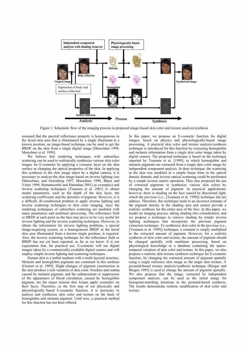
Figure 1. Schematic flow of the imaging process in proposed image-based skin color and texture analysis/synthesis assumed that the spectral reflectance property is homogeneous in the facial skin area that is illuminated by a single illuminant at a known position, an image-based technique can be used to get the BRDF on the skin from a single digital image [Marschner 1998, Marschner et al. 1999].
We believe that rendering techniques with subsurface scattering can be used to realistically synthesize various skin color images for E-cosmetic by applying a cosmetic layer on the skin surface or changing the optical properties of the skin. In applying this synthesis to the skin image taken by a digital camera, it is necessary to analyze the skin image based on inverse lighting (see [Marschner, and Greenberg 1997, Marschner 1998, Blanz and Vetter 1999, Ramamoorthi and Hanrahan 2001] as examples) and inverse scattering techniques [Tsumura et al. 2001] to obtain model parameters, such as the depth of the skin layer, the scattering coefficients and the densities of pigment. However, it is a difficult, ill-conditioned problem to apply inverse lighting and inverse scattering techniques to skin color imaging, since the rendering techniques of subsurface scattering are modeled with many parameters and nonlinear processing. The reflectance field or BRDF at each point on the face may prove to be very useful for inverse lighting and the inverse scattering techniques. However, to obtain the information for inverse lighting problems, a special image-acquiring system, or a homogeneous BRDF in the facial skin area illuminated from a known single position, is required. Also, the inverse scattering technique for the reflectance field or BRDF has not yet been reported, as far as we know. It is our expectation that, for practical use, E-cosmetic will use digital images taken by a commercially-available digital camera and will employ simple inverse lighting and scattering techniques.
Human skin is a turbid medium with a multi-layered structure. Melanin and hemoglobin pigments are contained in this medium [Gemert et al. 1989]. Slight changes of pigment construction in the skin produce a rich variation of skin color. Freckles and suntan, caused by melanin pigment, and the enhancement or suppression of the appearance of blood circulation, caused by hemoglobin pigment, are the major reasons that Asians apply cosmetics on their faces. Therefore, as the first step of our physically and physiologically-based E-cosmetic function, it is necessary to analyze and synthesize skin color and texture on the basis of hemoglobin and melanin pigment. Until now, a practical method for this function has not been offered.
In this paper, we propose an E-cosmetic function for digital images, based on physics and physiologically-based image processing. A practical skin color and texture analysis/synthesis technique is introduced for this function by extracting hemoglobin and melanin information from a single skin color image taken by digital camera. The proposed technique is based on the technique reported by Tsumura et al. [1999], in which hemoglobin and melanin pigments are extracted from a single skin color image by independent component analysis. In their technique, the scattering in the skin was modeled in a simple linear form in the optical density domain, and inverse optical scattering could be performed by a simple inverse matrix operation. They also proposed the use of extracted pigments to synthesize various skin colors by changing the amount of pigment. In practical applications, however, there is shading on the face caused by directional light, which the previous (i.e., [Tsumura et al. 1999]) technique did not address. Therefore, this technique leads to an incorrect estimate of the pigment density in the shading area and cannot provide a realistic synthesis for the entire area of the face. In this paper, we model an imaging process, taking shading into consideration, and we propose a technique to remove shading by simple inverse lighting techniques that incorporate the previous pigment extraction technique. To synthesize skin color in the previous (i.e., [Tsumura et al. 1999]) technique, a constant is simply multiplied to the extracted amount of pigment. However, for a realistic synthesis of skin color and texture, the amount of pigment should be changed spatially with nonlinear processing, based on physiological knowledge or a database containing the spatio-temporal variation of skin color and texture. In this paper, we also propose a realistic skin texture synthesis technique for E-cosmetic function, by changing the extracted amount of pigment spatially using a single reference skin image as the target skin texture. A pyramid-based texture analysis/synthesis technique [Heeger and Bergen 1995] is used to change the amount of pigment spatially. We also propose that the image, extracted by independent component analysis, can be used as the initial image for histogram-matching iterations in the pyramid-based synthesis. The results demonstrate realistic modification of skin color and texture.
Physiologically-basedimage processing
Independent component analysis with shading removal
Separation of body and surface reflection
Surface reflection
Body reflection
Shading
Hemoglobin
Melanin
Analysis SynthesisProcess
Original image Synthesized image
Physiologically-basedimage processing
Independent component analysis with shading removal
Separation of body and surface reflection
Surface reflection
Body reflection
Shading
Hemoglobin
Melanin
Analysis SynthesisProcess
Original image Synthesized image
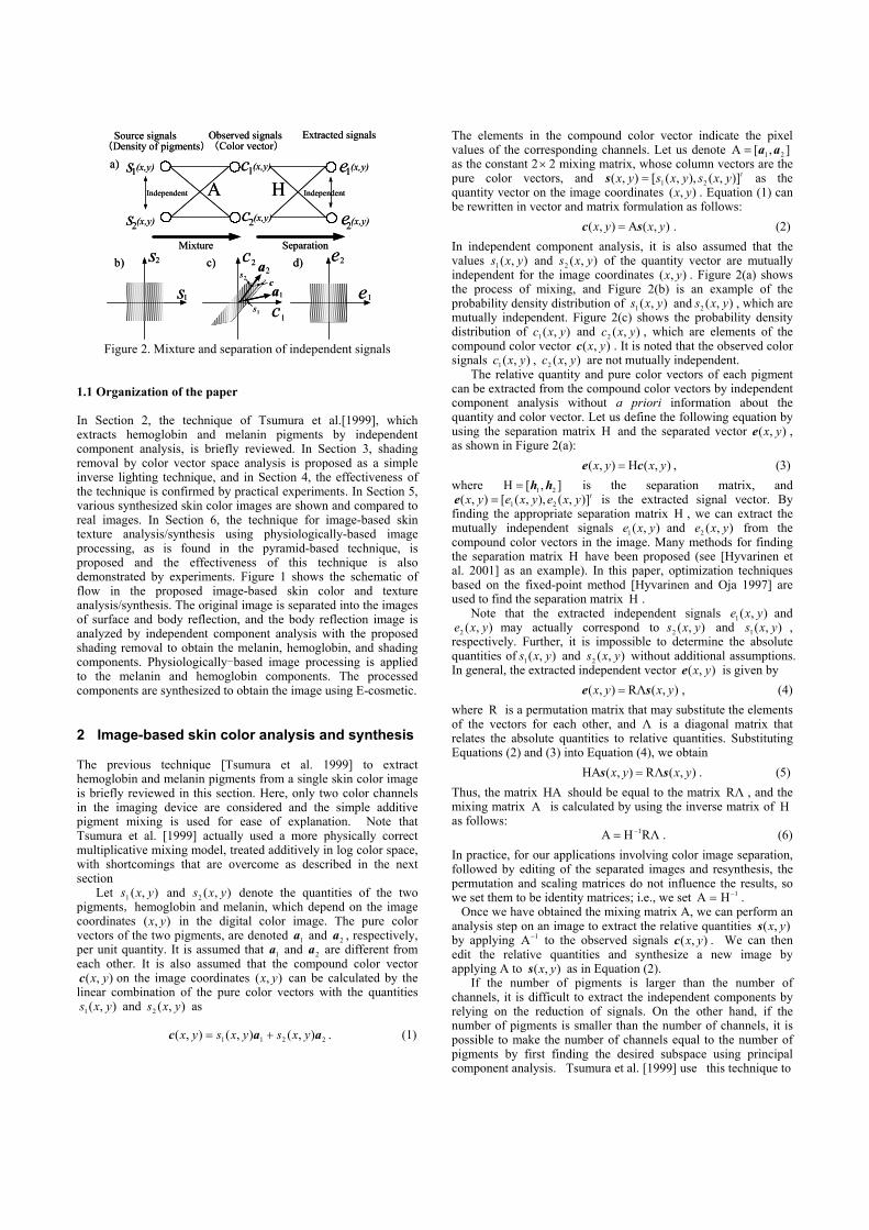
Figure 2. Mixture and separation of independent signals 1.1 Organization of the paper In Section 2, the technique of Tsumura et al.[1999], which extracts hemoglobin and melanin pigments by independent component analysis, is briefly reviewed. In Section 3, shading removal by color vector space analysis is proposed as a simple inverse lighting technique, and in Section 4, the effectiveness of the technique is confirmed by practical experiments. In Section 5, various synthesized skin color images are shown and compared to real images. In Section 6, the technique for image-based skin texture analysis/synthesis using physiologically-based image processing, as is found in the pyramid-based technique, is proposed and the effectiveness of this technique is also demonstrated by experiments. Figure 1 shows the schematic of flow in the proposed image-based skin color and texture analysis/synthesis. The original image is separated into the images of surface and body reflection, and the body reflection image is analyzed by independent component analysis with the proposed shading removal to obtain the melanin, hemoglobin, and shading components. Physiologically-based image processing is applied to the melanin and hemoglobin components. The processed components are synthesized to obtain the image using E-cosmetic. 2 Image-based skin color analysis and synthesis The previous technique [Tsumura et al. 1999] to extract hemoglobin and melanin pigments from a single skin color image is briefly reviewed in this section. Here, only two color channels in the imaging device are considered and the simple additive pigment mixing is used for ease of explanation. Note that Tsumura et al. [1999] actually used a more physically correct multiplicative mixing model, treated additively in log color space, with shortcomings that are overcome as described in the next section
Let ),(1 yxs and ),(2 yxs denote the quantities of the two pigments, hemoglobin and melanin, which depend on the image coordinates ),( yx in the digital color image. The pure color vectors of the two pigments, are denoted 1a and 2a , respectively, per unit quantity. It is assumed that 1a and 2a are different from each other. It is also assumed that the compound color vector
),( yxc on the image coordinates ),( yx can be calculated by the linear combination of the pure color vectors with the quantities
),(1 yxs and ),(2 yxs as
2211 ),(),(),( aac yxsyxsyx += . (1)
The elements in the compound color vector indicate the pixel values of the corresponding channels. Let us denote ],[A 21 aa= as the constant 2× 2 mixing matrix, whose column vectors are the pure color vectors, and tyxsyxsyx )],(),,([),( 21=s as the quantity vector on the image coordinates ),( yx . Equation (1) can be rewritten in vector and matrix formulation as follows:
),(A),( yxyx sc = . (2) In independent component analysis, it is also assumed that the values ),(1 yxs and ),(2 yxs of the quantity vector are mutually independent for the image coordinates ),( yx . Figure 2(a) shows the process of mixing, and Figure 2(b) is an example of the probability density distribution of ),(1 yxs and ),(2 yxs , which are mutually independent. Figure 2(c) shows the probability density distribution of ),(1 yxc and ),(2 yxc , which are elements of the compound color vector ),( yxc . It is noted that the observed color signals ),(1 yxc , ),(2 yxc are not mutually independent.
The relative quantity and pure color vectors of each pigment can be extracted from the compound color vectors by independent component analysis without a priori information about the quantity and color vector. Let us define the following equation by using the separation matrix H and the separated vector ),( yxe , as shown in Figure 2(a):
),(H),( yxyx ce = , (3) where ],[H 21 hh= is the separation matrix, and
tyxeyxeyx )],(),,([),( 21=e is the extracted signal vector. By finding the appropriate separation matrix H , we can extract the mutually independent signals ),(1 yxe and ),(2 yxe from the compound color vectors in the image. Many methods for finding the separation matrix H have been proposed (see [Hyvarinen et al. 2001] as an example). In this paper, optimization techniques based on the fixed-point method [Hyvarinen and Oja 1997] are used to find the separation matrix H .
Note that the extracted independent signals ),(1 yxe and ),(2 yxe may actually correspond to ),(2 yxs and ),(1 yxs ,
respectively. Further, it is impossible to determine the absolute quantities of ),(1 yxs and ),(2 yxs without additional assumptions. In general, the extracted independent vector ),( yxe is given by ),(RΛ),( yxyx se = , (4) where R is a permutation matrix that may substitute the elements of the vectors for each other, and Λ is a diagonal matrix that relates the absolute quantities to relative quantities. Substituting Equations (2) and (3) into Equation (4), we obtain
),(RΛ),(HA yxyx ss = . (5) Thus, the matrix HA should be equal to the matrix RΛ , and the mixing matrix A is calculated by using the inverse matrix of H as follows:
RΛHA 1−= . (6) In practice, for our applications involving color image separation, followed by editing of the separated images and resynthesis, the permutation and scaling matrices do not influence the results, so we set them to be identity matrices; i.e., we set 1HA −= . Once we have obtained the mixing matrix A, we can perform an analysis step on an image to extract the relative quantities ),( yxs by applying 1A− to the observed signals ),( yxc . We can then edit the relative quantities and synthesize a new image by applying A to ),( yxs as in Equation (2).
If the number of pigments is larger than the number of channels, it is difficult to extract the independent components by relying on the reduction of signals. On the other hand, if the number of pigments is smaller than the number of channels, it is possible to make the number of channels equal to the number of pigments by first finding the desired subspace using principal component analysis. Tsumura et al. [1999] use this technique to
s1(x,y)
Observed signals(Color vector)
Source signals (Density of pigments)
2s
a1
a2c
1
s2
s
c
c
e
e
1s
2c
1c
2e
1es
Mixture Separation
Independent A H Independent
a)
b) c) d)
2(x,y) 2(x,y)
1(x,y) 1(x,y)
2(x,y)
Extracted signals
s1(x,y)
Observed signals(Color vector)
Source signals (Density of pigments)
2s
a1
a2c
1
s2
s
c
c
e
e
1s
2c
1c
2e
1es
Mixture Separation
Independent A H Independent
a)
b) c) d)
2(x,y) 2(x,y)
1(x,y) 1(x,y)
2(x,y)
Extracted signals
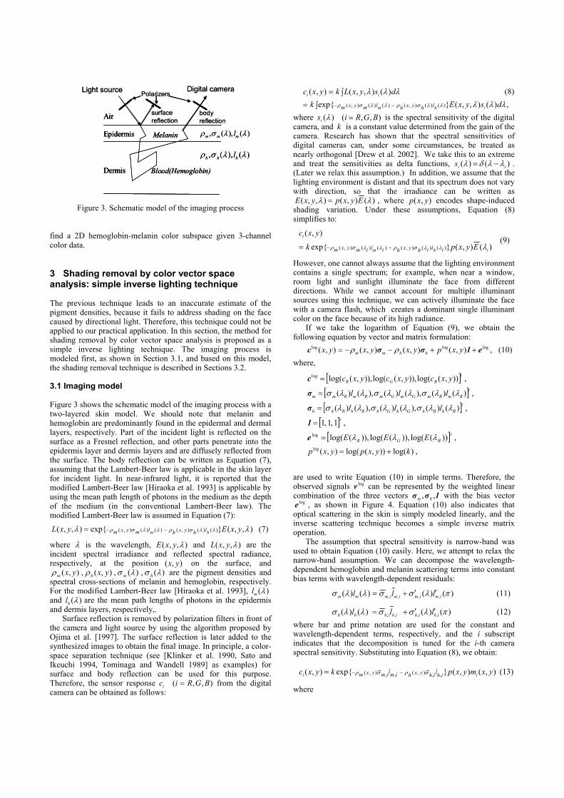
Figure 3. Schematic model of the imaging process find a 2D hemoglobin-melanin color subspace given 3-channel color data. 3 Shading removal by color vector space analysis: simple inverse lighting technique The previous technique leads to an inaccurate estimate of the pigment densities, because it fails to address shading on the face caused by directional light. Therefore, this technique could not be applied to our practical application. In this section, the method for shading removal by color vector space analysis is proposed as a simple inverse lighting technique. The imaging process is modeled first, as shown in Section 3.1, and based on this model, the shading removal technique is described in Sections 3.2. 3.1 Imaging model Figure 3 shows the schematic model of the imaging process with a two-layered skin model. We should note that melanin and hemoglobin are predominantly found in the epidermal and dermal layers, respectively. Part of the incident light is reflected on the surface as a Fresnel reflection, and other parts penetrate into the epidermis layer and dermis layers and are diffusely reflected from the surface. The body reflection can be written as Equation (7), assuming that the Lambert-Beer law is applicable in the skin layer for incident light. In near-infrared light, it is reported that the modified Lambert-Beer law [Hiraoka et al. 1993] is applicable by using the mean path length of photons in the medium as the depth of the medium (in the conventional Lambert-Beer law). The modified Lambert-Beer law is assumed in Equation (7):
),,(}exp{),,( )()(),()()(),( λλ λλσρλλσρ yxEyxL hm lhyxhlmyxm −−= (7) where λ is the wavelength, ),,( λyxE and ),,( λyxL are the incident spectral irradiance and reflected spectral radiance, respectively, at the position ),( yx on the surface, and
),( yxmρ , ),( yxhρ , )(λσ m , )(λσ h are the pigment densities and spectral cross-sections of melanin and hemoglobin, respectively. For the modified Lambert-Beer law [Hiraoka et al. 1993], )(λml and )(λhl are the mean path lengths of photons in the epidermis and dermis layers, respectively,.
Surface reflection is removed by polarization filters in front of the camera and light source by using the algorithm proposed by Ojima et al. [1997]. The surface reflection is later added to the synthesized images to obtain the final image. In principle, a color-space separation technique (see [Klinker et al. 1990, Sato and Ikeuchi 1994, Tominaga and Wandell 1989] as examples) for surface and body reflection can be used for this purpose. Therefore, the sensor response ),,( BGRici = from the digital camera can be obtained as follows:
∫= λλλ dsyxLkyxc ii )(),,(),( (8)
,)(),,(}exp{ )()(),()()(),(∫= −− λλλλλσρλλσρ dsyxEk ihm lhyxhlmyxm where ),,()( BGRisi =λ is the spectral sensitivity of the digital camera, and k is a constant value determined from the gain of the camera. Research has shown that the spectral sensitivities of digital cameras can, under some circumstances, be treated as nearly orthogonal [Drew et al. 2002]. We take this to an extreme and treat the sensitivities as delta functions, )()( iis λλδλ −= . (Later we relax this assumption.) In addition, we assume that the lighting environment is distant and that its spectrum does not vary with direction, so that the irradiance can be written as
)(),(),,( λλ EyxpyxE = , where ),( yxp encodes shape-induced shading variation. Under these assumptions, Equation (8) simplifies to:
)(),(}exp{
),(
)()(),()()(),( ihm
i
Eyxpk
yxc
ilihyxhilimyxm λλλσρλλσρ −−= (9)
However, one cannot always assume that the lighting environment contains a single spectrum; for example, when near a window, room light and sunlight illuminate the face from different directions. While we cannot account for multiple illuminant sources using this technique, we can actively illuminate the face with a camera flash, which creates a dominant single illuminant color on the face because of its high radiance.
If we take the logarithm of Equation (9), we obtain the following equation by vector and matrix formulation:
logloglog ),(),(),(),( e1σσc ++−−= yxpyxyxyx hhmm ρρ , (10) where,
[ ]tBGR yxcyxcyxc )),(log()),,(log()),,(log(log =c ,
[ ]tBmBmGmGmRmRmm lll )()(),()(),()( λλσλλσλλσ=σ ,
[ ]tBhBhGhGhRhRhh lll )()(),()(),()( λλσλλσλλσ=σ ,
[ ]t1,1,1=1 ,
[ ]tBGR EEE ))(log()),(log()),(log(log λλλ=e ,
)log()),(log(),(log kyxpyxp += ,
are used to write Equation (10) in simple terms. Therefore, the observed signals logv can be represented by the weighted linear combination of the three vectors 1σσ ,, hm with the bias vector
loge , as shown in Figure 4. Equation (10) also indicates that optical scattering in the skin is simply modeled linearly, and the inverse scattering technique becomes a simple inverse matrix operation.
The assumption that spectral sensitivity is narrow-band was used to obtain Equation (10) easily. Here, we attempt to relax the narrow-band assumption. We can decompose the wavelength-dependent hemoglobin and melanin scattering terms into constant bias terms with wavelength-dependent residuals:
)()()()( ,,,, πλσσλλσ imimimimmm lll ′′+= (11)
)()()()( ,,,, πλσσλλσ ihihihihhh lll ′′+= (12) where bar and prime notation are used for the constant and wavelength-dependent terms, respectively, and the i subscript indicates that the decomposition is tuned for the i-th camera spectral sensitivity. Substituting into Equation (8), we obtain:
),(),(}exp{),( ,,),(,,),( yxmyxpkyxc ii ihlihyxhimlimyxm σρσρ −−= (13)
where
Air
Epidermis
Dermis
Melanin
Blood(Hemoglobin)
Light source Digital camera
surface reflection
bodyreflection
)(),(, λλσρ mmm l
)(),(, λλσρ hhh l
Polarizers
Air
Epidermis
Dermis
Melanin
Blood(Hemoglobin)
Air
Epidermis
Dermis
Melanin
Blood(Hemoglobin)
Light source Digital camera
surface reflection
bodyreflection
)(),(, λλσρ mmm l
)(),(, λλσρ hhh l
Polarizers
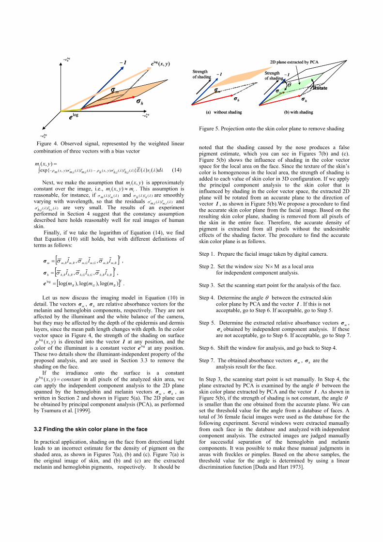
Figure 4. Observed signal, represented by the weighted linear
combination of three vectors with a bias vector
=),( yxmi ∫ ′′−′′− λλλλλσρλλσρ disEihlihyxhimlimyxm )()(}exp{ )(,)(,),()(,)(,),( (14)
Next, we make the assumption that ),( yxmi is approximately
constant over the image, i.e., ii myxm ≈),( . This assumption is reasonable, for instance, if )()( λλσ mlm and )()( λλσ hlh are smoothly varying with wavelength, so that the residuals )()(, , λλσ imlim ′′ and
)()(, , λλσ ihlih ′′ are very small. The results of an experiment performed in Section 4 suggest that the constancy assumption described here holds reasonably well for real images of human skin.
Finally, if we take the logarithm of Equation (14), we find that Equation (10) still holds, but with different definitions of terms as follows:
[ ]tBmBmGmGmRmRmm lll ,,,,,, ,, σσσ=σ ,
[ ]tBhBhGhGhRhRhh lll ,,,,,, ,, σσσ=σ ,
[ ]tBGR mmm )log(),log(),log(log =e .
Let us now discuss the imaging model in Equation (10) in detail. The vectors mσ , hσ are relative absorbance vectors for the melanin and hemoglobin components, respectively. They are not affected by the illuminant and the white balance of the camera, but they may be affected by the depth of the epidermis and dermis layers, since the mean path length changes with depth. In the color vector space in Figure 4, the strength of the shading on surface
),(log yxp is directed into the vector 1 at any position, and the color of the illuminant is a constant vector loge at any position. These two details show the illuminant-independent property of the proposed analysis, and are used in Section 3.3 to remove the shading on the face.
If the irradiance onto the surface is a constant constantyxp =),(log in all pixels of the analyzed skin area, we
can apply the independent component analysis to the 2D plane spanned by the hemoglobin and melanin vectors mσ , hσ , as written in Section 2 and shown in Figure 5(a). The 2D plane can be obtained by principal component analysis (PCA), as performed by Tsumura et al. [1999]. 3.2 Finding the skin color plane in the face In practical application, shading on the face from directional light leads to an incorrect estimate for the density of pigment on the shaded area, as shown in Figures 7(a), (b) and (c). Figure 7(a) is the original image of skin, and (b) and (c) are the extracted melanin and hemoglobin pigments, respectively. It should be
Figure 5. Projection onto the skin color plane to remove shading noted that the shading caused by the nose produces a false pigment estimate, which you can see in Figures 7(b) and (c). Figure 5(b) shows the influence of shading in the color vector space for the local area on the face. Since the texture of the skin’s color is homogeneous in the local area, the strength of shading is added to each value of skin color in 3D configuration. If we apply the principal component analysis to the skin color that is influenced by shading in the color vector space, the extracted 2D plane will be rotated from an accurate plane to the direction of vector 1 , as shown in Figure 5(b).We propose a procedure to find the accurate skin color plane from the facial image. Based on the resulting skin color plane, shading is removed from all pixels of the skin in the entire face. Therefore, the accurate density of pigment is extracted from all pixels without the undesirable effects of the shading factor. The procedure to find the accurate skin color plane is as follows. Step 1. Prepare the facial image taken by digital camera. Step 2. Set the window size MN× as a local area
for independent component analysis. Step 3. Set the scanning start point for the analysis of the face. Step 4. Determine the angle θ between the extracted skin
color plane by PCA and the vector 1 . If this is not acceptable, go to Step 6. If acceptable, go to Step 5.
Step 5. Determine the extracted relative absorbance vectors mσ ,
hσ obtained by independent component analysis. If these are not acceptable, go to Step 6. If acceptable, go to Step 7.
Step 6. Shift the window for analysis, and go back to Step 4. Step 7. The obtained absorbance vectors mσ , hσ are the
analysis result for the face. In Step 3, the scanning start point is set manually. In Step 4, the plane extracted by PCA is examined by the angle θ between the skin color plane extracted by PCA and the vector 1 . As shown in Figure 5(b), if the strength of shading is not constant, the angle θ is smaller than the one obtained from the accurate plane. We can set the threshold value for the angle from a database of faces. A total of 36 female facial images were used as the database for the following experiment. Several windows were extracted manually from each face in the database and analyzed with independent component analysis. The extracted images are judged manually for successful separation of the hemoglobin and melanin components. It was possible to make these manual judgments in areas with freckles or pimples. Based on the above samples, the threshold value for the angle is determined by using a linear discrimination function [Duda and Hart 1973].
(a) without shading
Strength of shading 1−
mσ
hσ
(b) with shading
θ Rotate
2D plane extracted by PCA
Strength of shading
1−
mσhσ
(a) without shading
Strength of shading 1−
mσ
hσ
(b) with shading
θ Rotate
2D plane extracted by PCA
Strength of shading
1−
mσhσ
loge
1−
mσ
hσ
),(log yxc
logRc−
logGc−
logBc−
loge
1−
mσ
hσ
),(log yxc
logRc−
logGc−
logBc−
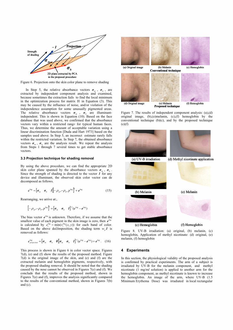
Figure 6. Projection onto the skin color plane to remove shading
In Step 5, the relative absorbance vectors mσ , hσ , are extracted by independent component analysis and examined, because sometimes the extraction fails to find the local minimum in the optimization process for matrix H in Equation (3). This may be caused by the influence of noise, and/or violation of the independence assumption for some unusually pigmented areas. The relative absorbance vectors mσ , hσ are illuminant-independent. This is shown in Equation (10). Based on the face database that was used above, we confirmed that the absorbance vectors vary within a restricted range for typical human faces. Thus, we determine the amount of acceptable variation using a linear discrimination function [Duda and Hart 1973] based on the samples used above. In Step 5, an incorrect estimate rarely falls within the restricted variation. In Step 7, the obtained absorbance vectors mσ , hσ are the analysis result. We repeat the analysis from Steps 1 through 7 several times to get stable absorbance vectors. 3.3 Projection technique for shading removal By using the above procedure, we can find the appropriate 2D skin color plane spanned by the absorbance vectors mσ , hσ . Since the strength of shading is directed to the vector 1 for any device and illuminant, the observed skin color vector can de decomposed as follows.
[ ][ ] logloglog ,, e1σσc +−−=tphmhm ρρ (15)
Rearranging, we arrive at:,
[ ] [ ] )(,, loglog1log ec1σσ −=−− −hmhm
tpρρ The bias vector loge is unknown. Therefore, if we assume that the smallest value of each pigment in the skin image is zero, then loge is calculated by )),((min log
,
log yxve iyxi = for each band of color. Based on the above decomposition, the shading term 1pw is removed as follows:
[ ][ ] logloglog1log )( eec1σσ0σσc +−= −hmhmprojection . (16)
This process is shown in Figure 6 in color vector space. Figures 7(d), (e) and (f) show the results of the proposed method. Figure 7(d) is the original image of the skin, and (e) and (f) are the extracted melanin and hemoglobin pigments, respectively, with the proposed shading removal. It should be noted that the shading caused by the nose cannot be observed in Figures 7(e) and (f). We conclude that the results of the proposed method, shown in Figures 7(e) and (f), improves the analysis significantly compared to the results of the conventional method, shown in Figures 7(b) and (c).
Figure 7. The results of independent component analysis: (a),(d) original image, (b),(e)melanin, (c),(f) hemoglobin by the conventional technique (b)(c), and by the proposed technique (e)(f) Figure 8. UV-B irradiation: (a) original, (b) melanin, (c) hemoglobin, Application of methyl nicotinate: (d) original, (e) melanin, (f) hemoglobin 4 Experiments In this section, the physiological validity of the proposed analysis is confirmed by practical experiments. The arm of a subject is irradiated by UV-B for the melanin component, and methyl nicotinate (1 mg/ml solution) is applied to another arm for the hemoglobin component, as methyl nicotinate is known to increase the hemoglobin. An image of the arm, where UV-B (1.5 Minimum Erythema Dose) was irradiated in local rectangular
2D plane extracted by PCA in the proposed procedure
Strength of shading
1−
mσ
hσ
Projection
2D plane extracted by PCA in the proposed procedure
Strength of shading
1−
mσ
hσ
Projection
(a) Original image (b) Melanin (c) Hemoglobin
(d) Original image (e) Melanin (f) Hemoglobin
Conventional technique
Proposed technique
(a) Original image (b) Melanin (c) Hemoglobin
(d) Original image (e) Melanin (f) Hemoglobin
Conventional technique
Proposed technique
(a) UV-B irradiation
(b) Melanin
(c) Hemoglobin
(e) Melanin
(f) Hemoglobin
(d) Methyl nicotinate application(a) UV-B irradiation
(b) Melanin
(c) Hemoglobin
(e) Melanin
(f) Hemoglobin
(d) Methyl nicotinate application
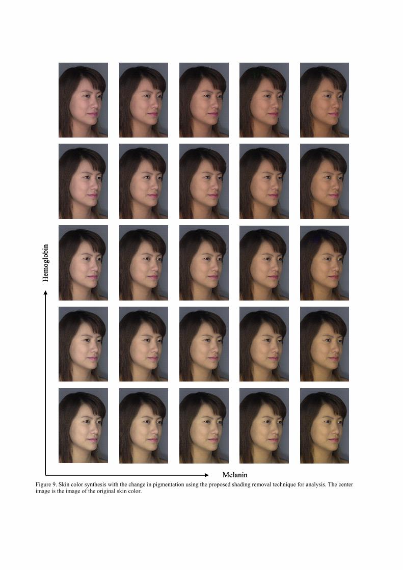
Figure 9. Skin color synthesis with the change in pigmentation using the proposed shading removal technique for analysis. The center image is the image of the original skin color.
Melanin
Hem
oglo
bin
Melanin
Hem
oglo
bin
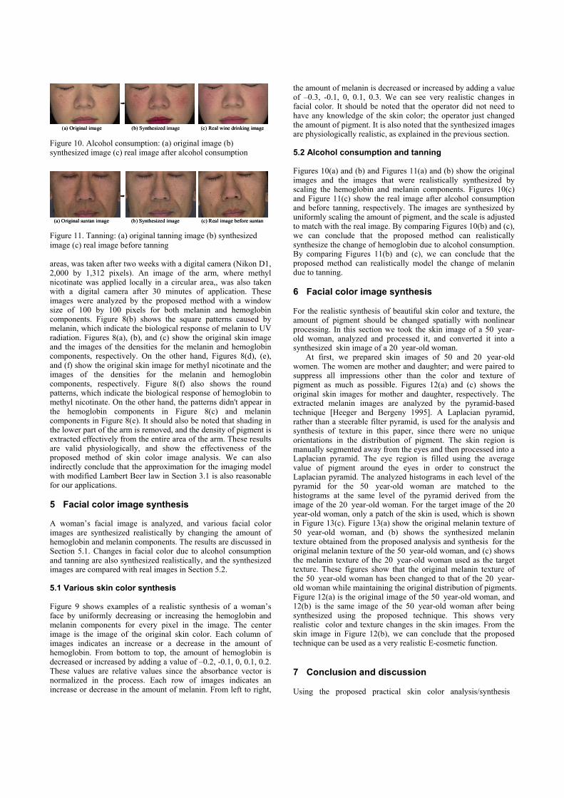
Figure 10. Alcohol consumption: (a) original image (b) synthesized image (c) real image after alcohol consumption Figure 11. Tanning: (a) original tanning image (b) synthesized image (c) real image before tanning areas, was taken after two weeks with a digital camera (Nikon D1, 2,000 by 1,312 pixels). An image of the arm, where methyl nicotinate was applied locally in a circular area,, was also taken with a digital camera after 30 minutes of application. These images were analyzed by the proposed method with a window size of 100 by 100 pixels for both melanin and hemoglobin components. Figure 8(b) shows the square patterns caused by melanin, which indicate the biological response of melanin to UV radiation. Figures 8(a), (b), and (c) show the original skin image and the images of the densities for the melanin and hemoglobin components, respectively. On the other hand, Figures 8(d), (e), and (f) show the original skin image for methyl nicotinate and the images of the densities for the melanin and hemoglobin components, respectively. Figure 8(f) also shows the round patterns, which indicate the biological response of hemoglobin to methyl nicotinate. On the other hand, the patterns didn't appear in the hemoglobin components in Figure 8(c) and melanin components in Figure 8(e). It should also be noted that shading in the lower part of the arm is removed, and the density of pigment is extracted effectively from the entire area of the arm. These results are valid physiologically, and show the effectiveness of the proposed method of skin color image analysis. We can also indirectly conclude that the approximation for the imaging model with modified Lambert Beer law in Section 3.1 is also reasonable for our applications. 5 Facial color image synthesis A woman’s facial image is analyzed, and various facial color images are synthesized realistically by changing the amount of hemoglobin and melanin components. The results are discussed in Section 5.1. Changes in facial color due to alcohol consumption and tanning are also synthesized realistically, and the synthesized images are compared with real images in Section 5.2. 5.1 Various skin color synthesis Figure 9 shows examples of a realistic synthesis of a woman’s face by uniformly decreasing or increasing the hemoglobin and melanin components for every pixel in the image. The center image is the image of the original skin color. Each column of images indicates an increase or a decrease in the amount of hemoglobin. From bottom to top, the amount of hemoglobin is decreased or increased by adding a value of –0.2, -0.1, 0, 0.1, 0.2. These values are relative values since the absorbance vector is normalized in the process. Each row of images indicates an increase or decrease in the amount of melanin. From left to right,
the amount of melanin is decreased or increased by adding a value of –0.3, -0.1, 0, 0.1, 0.3. We can see very realistic changes in facial color. It should be noted that the operator did not need to have any knowledge of the skin color; the operator just changed the amount of pigment. It is also noted that the synthesized images are physiologically realistic, as explained in the previous section. 5.2 Alcohol consumption and tanning Figures 10(a) and (b) and Figures 11(a) and (b) show the original images and the images that were realistically synthesized by scaling the hemoglobin and melanin components. Figures 10(c) and Figure 11(c) show the real image after alcohol consumption and before tanning, respectively. The images are synthesized by uniformly scaling the amount of pigment, and the scale is adjusted to match with the real image. By comparing Figures 10(b) and (c), we can conclude that the proposed method can realistically synthesize the change of hemoglobin due to alcohol consumption. By comparing Figures 11(b) and (c), we can conclude that the proposed method can realistically model the change of melanin due to tanning. 6 Facial color image synthesis For the realistic synthesis of beautiful skin color and texture, the amount of pigment should be changed spatially with nonlinear processing. In this section we took the skin image of a 50 year-old woman, analyzed and processed it, and converted it into a synthesized skin image of a 20 year-old woman.
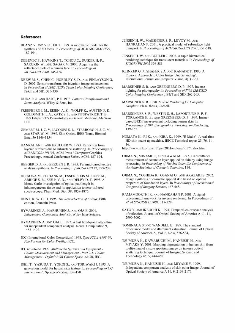
At first, we prepared skin images of 50 and 20 year-old women. The women are mother and daughter; and were paired to suppress all impressions other than the color and texture of pigment as much as possible. Figures 12(a) and (c) shows the original skin images for mother and daughter, respectively. The extracted melanin images are analyzed by the pyramid-based technique [Heeger and Bergeny 1995]. A Laplacian pyramid, rather than a steerable filter pyramid, is used for the analysis and synthesis of texture in this paper, since there were no unique orientations in the distribution of pigment. The skin region is manually segmented away from the eyes and then processed into a Laplacian pyramid. The eye region is filled using the average value of pigment around the eyes in order to construct the Laplacian pyramid. The analyzed histograms in each level of the pyramid for the 50 year-old woman are matched to the histograms at the same level of the pyramid derived from the image of the 20 year-old woman. For the target image of the 20 year-old woman, only a patch of the skin is used, which is shown in Figure 13(c). Figure 13(a) show the original melanin texture of 50 year-old woman, and (b) shows the synthesized melanin texture obtained from the proposed analysis and synthesis for the original melanin texture of the 50 year-old woman, and (c) shows the melanin texture of the 20 year-old woman used as the target texture. These figures show that the original melanin texture of the 50 year-old woman has been changed to that of the 20 year-old woman while maintaining the original distribution of pigments. Figure 12(a) is the original image of the 50 year-old woman, and 12(b) is the same image of the 50 year-old woman after being synthesized using the proposed technique. This shows very realistic color and texture changes in the skin images. From the skin image in Figure 12(b), we can conclude that the proposed technique can be used as a very realistic E-cosmetic function. 7 Conclusion and discussion Using the proposed practical skin color analysis/synthesis
(a) Original image (b) Synthesized image (c) Real wine drinking image(a) Original image (b) Synthesized image (c) Real wine drinking image
(a) Original suntan image (b) Synthesized image (c) Real image before suntan(a) Original suntan image (b) Synthesized image (c) Real image before suntan
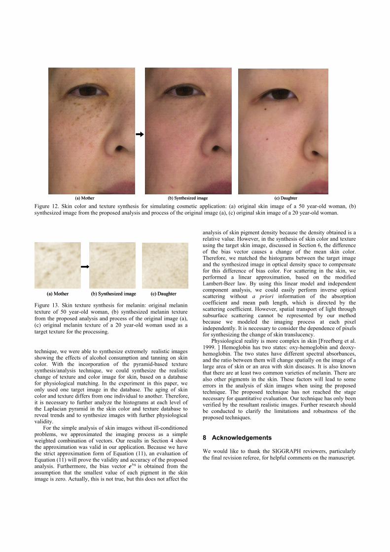
Figure 12. Skin color and texture synthesis for simulating cosmetic application: (a) original skin image of a 50 year-old woman, (b) synthesized image from the proposed analysis and process of the original image (a), (c) original skin image of a 20 year-old woman. Figure 13. Skin texture synthesis for melanin: original melanin texture of 50 year-old woman, (b) synthesized melanin texture from the proposed analysis and process of the original image (a), (c) original melanin texture of a 20 year-old woman used as a target texture for the processing. technique, we were able to synthesize extremely realistic images showing the effects of alcohol consumption and tanning on skin color. With the incorporation of the pyramid-based texture synthesis/analysis technique, we could synthesize the realistic change of texture and color image for skin, based on a database for physiological matching. In the experiment in this paper, we only used one target image in the database. The aging of skin color and texture differs from one individual to another. Therefore, it is necessary to further analyze the histograms at each level of the Laplacian pyramid in the skin color and texture database to reveal trends and to synthesize images with further physiological validity.
For the simple analysis of skin images without ill-conditioned problems, we approximated the imaging process as a simple weighted combination of vectors. Our results in Section 4 show the approximation was valid in our application. Because we have the strict approximation form of Equation (11), an evaluation of Equation (11) will prove the validity and accuracy of the proposed analysis. Furthermore, the bias vector loge is obtained from the assumption that the smallest value of each pigment in the skin image is zero. Actually, this is not true, but this does not affect the
analysis of skin pigment density because the density obtained is a relative value. However, in the synthesis of skin color and texture using the target skin image, discussed in Section 6, the difference of the bias vector causes a change of the mean skin color. Therefore, we matched the histograms between the target image and the synthesized image in optical density space to compensate for this difference of bias color. For scattering in the skin, we performed a linear approximation, based on the modified Lambert-Beer law. By using this linear model and independent component analysis, we could easily perform inverse optical scattering without a priori information of the absorption coefficient and mean path length, which is directed by the scattering coefficient. However, spatial transport of light through subsurface scattering cannot be represented by our method because we modeled the imaging process at each pixel independently. It is necessary to consider the dependence of pixels for synthesizing the change of skin translucency.
Physiological reality is more complex in skin [Freefberg et al. 1999. ] Hemoglobin has two states: oxy-hemoglobin and deoxy-hemoglobin. The two states have different spectral absorbances, and the ratio between them will change spatially on the image of a large area of skin or an area with skin diseases. It is also known that there are at least two common varieties of melanin. There are also other pigments in the skin. These factors will lead to some errors in the analysis of skin images when using the proposed technique. The proposed technique has not reached the stage necessary for quantitative evaluation. Our technique has only been verified by the resultant realistic images. Further research should be conducted to clarify the limitations and robustness of the proposed techniques. 8 Acknowledgements We would like to thank the SIGGRAPH reviewers, particularly the final revision referee, for helpful comments on the manuscript.
(a) Mother (b) Synthesized image (c) Daughter(a) Mother (b) Synthesized image (c) Daughter
(a) Mother (b) Synthesized image (c) Daughter(a) Mother (b) Synthesized image (c) Daughter
References BLANZ V. AND VETTER T. 1999. A morphable model for the
synthesis of 3D faces. In Proceedings of ACM SIGGRAPH'99, 187-194.
DEBEVEC P., HAWKINS T., TCHOU C., DUIKER H.-P.,
SAROKIN W., AND SAGAR M. 2000. Acquiring the reflectance field of a human face. In Proceedings of SIGGRAPH 2000, 145-156.
DREW M. S., CHEN C., HORDLEY S. D., AND FINLAYSON G,
D. 2002. Sensor transforms for invariant image enhancement. In Proceeding of IS&T /SID's Tenth Color Imaging Conference, IS&T and SID, 325-330.
DUDA R.O. AND HART, P.E. 1973. Pattern Classification and
Scene Analysis. Wiley & Sons, Inc. FREEFBERG I. M., EISEN A. Z., WOLFF K., AUSTEN F. K,
GOLDSMITH L.A., KATZ S. I., AND FITSPATRICK T. B. 1999 Fitzpatrick's Dermatology in General Medicine, McGraw Hill.
GEMERT M. J. C. V, JACQUES S. L., STERBORG H. J. C. M,
AND STAR W. M. 1989. Skin Optics. IEEE Trans. Biomed. Eng., 36 1146-1154.
HANRAHAN P. AND KRUEGER W. 1993. Reflection from
layered surfaces due to subsurface scattering. In Proceedings of ACM SIGGRAPH '93, ACM Press / Computer Graphics Proceedings, Annual Conference Series, ACM, 187-194.
HEEGER D. J. AND BERGEN J. R. 1995. Pyramid-based texture
analysis/synthesis. In Proceedings of SIGGRAPH 95, 229-238. HIRAOKA M., FIRBANK M., ESSENPREIS M., COPE M.,
ARRIGE S. R., ZEE P. V. D., AND DELPY D. T. 1993. A Monte Carlo investigation of optical pathlength in inhomogeneous tissue and its application to near-infrared spectroscopy. Phys. Med. Biol. 38, 1859-1876.
HUNT, R. W. G. H. 1995. The Reproduction of Colour, Fifth
edition, Fountain Press. HYVARINEN A., KARHUNEN J., AND OJA E. 2001.
Independent Component Analysis, Wiley Inter-Science. HYVARINEN A. AND OJA E. 1997. A fast fixed-point algorithm
for independent component analysis. Neural Computation 9, 1483-1492.
ICC (International Color Consortium) 1998. Spec ICC.1:1998-09,
File Format for Color Profiles. ICC. IEC 61966-2-1 1999. Multimedia Systems and Equipment -
Colour Measurement and Management - Part 2-1: Colour Management - Default RGB Colour Space -sRGB, IEC.
ISHII T., YASUDA T., YOKOI S., AND TORIWAKI J. 1993. A
generation model for human skin texture. In Proceedings of CG International., Springer-Verlag, 139-150.
JENSEN H. W., MAESHNER S. R., LEVOY M., AND
HANRAHAN P. 2001. A practical model of subsurface light transport. In Proceedings of ACM SIGGRAPH 2001, 551-518.
JENSEN H. W. AND BUHLER J. 2002. A rapid hierarchical
rendering technique for translucent materials. In Proceedings of SIGGRAPH 2002 576-581.
KLINKER G. J., SHAFER S.A. AND KANADE T. 1990. A
Physical Approach to Color Image Understanding", International Journal on Computer Vision, 4(1) 7-38.
MARSHNER S. R. AND GREENBERG D. P. 1997. Inverse
lighting for photography. In Proceeding of Fifth IS&T/SID Color Imaging Conference , IS&T and SID, 262-265.
MARSHNER S. R. 1998. Inverse Rendering for Computer
Graphics. Ph.D. thesis, Cornell. MARSCHNER S. R., WESTIN S. H., LAFORTUNE E. P. F.,
TORRANCE K. E., AND GREENBERG D. P. 1999. Image-based BRDF measurement including human skin. In Proceedings of 10th Eurographics Workshop on Rendering, 139-152.
NUMATA K., RI K., AND KIRA K., 1999. "E-Make"; A real-time
HD skin-make-up machine. IEICE Technical report 23, 76, 11-16.
http://www.nhk.or.jp/strl/open2001/en/tenji/id17/index.html. OJIMA N., MINAMI T., AND KAWAI M. 1997. Transmittance
measurement of cosmetic layer applied on skin by using image processing. In Proceeding of The 3rd Scientific Conference of the Asian Societies of Cosmetic Scientists, 114.
OJIMA N., YOSHIDA K., OSANAI O., AND AKAZAKI S. 2002.
Image synthesis of cosmetic applied skin based on optical properties of foundation layers. In Proceedings of International Congress of Imaging Science, 467-468.
RAMAMOORTHI R. AND HANRAHAN P. 2001. A signal-
processing framework for inverse rendering. In Proceedings of ACM SIGGRAPH 2001, 117-128.
SATO Y. AND IKEUCHI K. 1994. Temporal-color space analysis
of reflection. Journal of Optical Society of America A 11, 11, 2990-3002.
TOMINAGA S. AND WANDELL B. 1989. The standard
reflectance model and illuminant estimation. Journal of Optical Society of America A, Vol. 6, No.4, 576-584,.
TSUMURA N., KAWABUCHI M., HANEISHI H., AND
MIYAKE Y. 2001. Mapping pigmentation in human skin from multi-channel visible spectrum image by inverse optical scattering technique. Journal of Imaging Science and Technology 45, 5, 444-450.
TSUMURA N., HANEISHI H., AND MIYAKE Y. 1999.
Independent component analysis of skin color image. Journal of Optical Society of America A 16, 9, 2169-2176.