Embed Size (px)
Citation preview

Obróbka Plastyczna Metali t. XXI nr 2 (2010) Procesy kształtowania wyrobów z blach
Mgr inŜ. Tadeusz DRENGER, mgr inŜ. Tomasz GĄDEK, mgr inŜ. Łukasz NOWACKI
mgr inŜ. Jan WIŚNIEWSKI Instytut Obróbki Plastycznej, Poznań
Innowacyjna technologia kształtowania obrotowego wytłoczek ze stopu niklu
z miejscowym podgrzewaniem laserowym
Innovative technology of rotary forming nickel alloy
drawpieces with local laser heating
Streszczenie Ze względu na trudności w kształtowaniu plastycznym stopów niklu autorzy prowadzą badania mające na celu
opracowanie optymalnych technologii podgrzewania materiału wiązką lasera w trakcie kształtowania obrotowego.
Badania są prowadzone w ramach projektu rozwojowego finansowanego przez Ministerstwo Nauki i Szkolnictwa
WyŜszego. W niniejszym artykule opisano stanowiska badawcze wraz z laserem oraz dwa sposoby kształtowania
wyoblaniem i zgniataniem obrotowym rzutowym na zimno i z podgrzewaniem materiału. Opisano teŜ sposób
podgrzewania i pomiar temperatury w procesie kształtowania elementów z blach ze stopu niklu Inconel 625 oraz
próby zgniatania obrotowego na zimno i wyoblania z podgrzewaniem laserowym.
Abstract Considering the difficulties met in plastic forming of nickel alloys, the authors conduct investigations aiming
at optimum technologies of laser beam heating of the material during rotary forming. The investigations are
effected within a development project financed by the Ministry of Science and Education. The present paper de-
scribes test stands provided with lasers and two methods of shaping by cold spinning and shear forming as well
as with material heating. A description of the way of heating and temperature measurement in the process
of forming parts Inconel 625 nickel alloy sheets and trials of cold flow forming and spinning with laser heating
can also be found.
Słowa kluczowe: wyoblanie, zgniatanie obrotowe, Inconel 625, kształtowanie obrotowe, podgrzewanie laserowe
Key words: spinning, flow forming, Inconel 625, rotary forming, laser heating
1. WSTĘP W przemyśle lotniczym, szczególnie na
elementy silników bardzo często stosowanym
materiałem jest nadstop niklu o nazwie han-
dlowej Inconel. Materiał Inconel 625 badany
w ramach projektu rozwojowego R1502703
naleŜy do materiałów trudno odkształcalnych.
UŜywa się go ze względu na duŜą odporność korozyjną i dobre właściwości wytrzymało-
ściowe w podwyŜszonych temperaturach [1].
W procesach produkcyjnych obróbki pla-
stycznej stopu niklu Inconel 625 występują graniczne odkształcenia, które nie powodują zmiany właściwości materiałowych.
1. INTRODUCTION
In the aerospace industry, an often applied
material is nickel superalloy with the trade
name of Inconel, particularly used for engine
elements. Inconel 625 material, examined
within the development project R1502703, is
a hard-to-deform one. It is used for its high
corrosion resistance and good strength proper-
ties at high temperatures [1].
In the production metal forming processes,
there are limits of strains which can be obtain
without changing material properties.

T. Drenger, T. Gądek, Ł. Nowacki, J. Wiśniewski
88
Procesy technologiczne stosowane w pro-
dukcji elementów silników z Inconelu 625
składają się z wielu operacji m.in.: gięcie, płyt-
kie tłoczenie, zwijanie, rozpęczanie, spawanie.
Powoduje to, Ŝe koszty produkcji są wysokie.
Występują takŜe duŜe wymagania dotyczące
kontroli elementów w czasie procesu produk-
cyjnego. Wprowadzenie kształtowania obroto-
wego do wykonywania części lotniczych jest
uzasadnione, poniewaŜ elementy silników nie
są produkowane wielkoseryjnie.
Punktowy styk narzędzi z kształtowanym
materiałem w procesie zgniatania obrotowego
i wyoblania powoduje, Ŝe siły występujące
w procesie są znacznie mniejsze niŜ w proce-
sach tłoczenia. Dodatkowe wprowadzenie
miejscowego podgrzewania daje szanse na
osiągnięcie oczekiwanych efektów. Celem ba-
dań wykonywanych w ramach projektu jest
ustalenie charakterystyki nadstopu niklu Inco-
nel 625 w zakresie struktury i właściwości me-
chanicznych oraz opracowanie parametrów
technologicznych obróbki cieplnej i parame-
trów technologicznych kształtowania obroto-
wego, w tym geometrii rolek roboczych. Nie-
rozłącznie związana z badaniami tej technolo-
gii jest znajomość struktury i właściwości me-
chanicznych nadstopu niklu, sposobu jego ob-
róbki cieplnej oraz rozkładu napręŜeń. Badania
te prowadzone są na Politechnice Warszaw-
skiej na Wydziale InŜynierii Materiałowej.
Badania te obejmują badania właściwości ma-
teriału wyjściowego, własności materiału
w czasie procesu technologicznego oraz bada-
nie własności wytłoczek próbnych.
2. BADANIA MATERIAŁOWE
W ramach badań przeprowadzono analizę składu chemicznego blach (rys. 1). W tablicy 1
przedstawiono wyniki analizy składu chemicz-
nego blach wyznaczonego przez Politechnikę Warszawską Wydział InŜynierii Materiałowej
[1].
The technological processes applied
in the production of engine elements of Inconel
625 include many operations, e.g. bending,
shallow stamping, coiling, bulging, welding.
This results in high production costs. There are
also high requirements concerning control
of the elements during the production process.
Introduction of rotary forming to the manufac-
ture of aerospace engines is justified by that
the engine elements are not produced in long
series.
Flow forming and spinning, due to spot
contact of the tools with the material being
formed, results in that the forces acting
in the process are much smaller than
in the processes of stamping. Additional intro-
duction of local heating makes it possible
to obtain the expected effects. The objective
of the investigation performed within the pro-
ject is to determine the characteristics of In-
conel 625 nickel superalloy in the scope of its
structure and mechanical properties and
to elaborate the technological parameters
of heat treatment and those of flow forming,
including the geometry of the working rolls.
Closely related to the investigation of the tech-
nology is the knowledge of the nickel super-
alloy structure and mechanical properties,
the way of its heat treatment and stress distri-
bution. Those investigations are performed
in the department of Material Engineering
of the Warsaw University of Technology.
The investigations include examination
of the initial material properties, material
properties during the technological process,
as well as examination of the properties of test
drawpieces.
2. MATERIAL INVESTIGATION
Within the investigation, an analysis
of the chemical composition of the metal
sheets has been performed (fig. 1). Table 1
presents the results of the chemical composi-
tion analysis determined by the Department
of Material Engineering of the Warsaw Uni-
versity of Technology [1].
Innowacyjna technologia kształtowania obrotowego wytłoczek ...
89
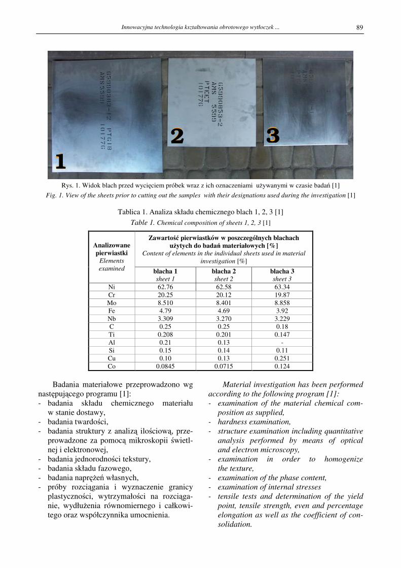
Rys. 1. Widok blach przed wycięciem próbek wraz z ich oznaczeniami uŜywanymi w czasie badań [1]
Fig. 1. View of the sheets prior to cutting out the samples with their designations used during the investigation [1]
Tablica 1. Analiza składu chemicznego blach 1, 2, 3 [1]
Table 1. Chemical composition of sheets 1, 2, 3 [1]
Zawartość pierwiastków w poszczególnych blachach uŜytych do badań materiałowych [%]
Content of elements in the individual sheets used in material
investigation [%]
Analizowane pierwiastki
Elements
examined blacha 1 sheet 1
blacha 2 sheet 2
blacha 3 sheet 3
Ni 62.76 62.58 63.34
Cr 20.25 20.12 19.87
Mo 8.510 8.401 8.858
Fe 4.79 4.69 3.92
Nb 3.309 3.270 3.229
C 0.25 0.25 0.18
Ti 0.208 0.201 0.147
Al 0.21 0.13 -
Si 0.15 0.14 0.11
Cu 0.10 0.13 0.251
Co 0.0845 0.0715 0.124
Badania materiałowe przeprowadzono wg
następującego programu [1]:
- badania składu chemicznego materiału
w stanie dostawy,
- badania twardości,
- badania struktury z analizą ilościową, prze-
prowadzone za pomocą mikroskopii świetl-
nej i elektronowej,
- badania jednorodności tekstury,
- badania składu fazowego,
- badania napręŜeń własnych,
- próby rozciągania i wyznaczenie granicy
plastyczności, wytrzymałości na rozciąga-
nie, wydłuŜenia równomiernego i całkowi-
tego oraz współczynnika umocnienia.
Material investigation has been performed
according to the following program [1]:
- examination of the material chemical com-
position as supplied,
- hardness examination,
- structure examination including quantitative
analysis performed by means of optical
and electron microscopy,
- examination in order to homogenize
the texture,
- examination of the phase content,
- examination of internal stresses
- tensile tests and determination of the yield
point, tensile strength, even and percentage
elongation as well as the coefficient of con-
solidation.
2 3
1

T. Drenger, T. Gądek, Ł. Nowacki, J. Wiśniewski
90
Wyniki tych badań przedstawione zostaną w innej publikacji.
Z punktu widzenia kształtowania obróbką plastyczną istotne są parametry uzyskane
w próbie rozciągania. Z atestu blachy nr 3 (cer-
tyfikat TW Metals) wynika, Ŝe wytrzymałość na rozciąganie wynosi Rm = 894 MPa, umowna
granica plastyczności Rp0,2 = 469 MPa, wydłu-
Ŝenie A = 49,7%
Przykładowy wynik rozciągania próbek
nr 3Wa i 3Wb pokazano na rysunku 2.
W oznaczeniu próbek pierwsza cyfra
oznacza numer arkusza, z którego wycięto
próbkę, litera "W" oznacza kierunek wzdłuŜ kierunku walcowania, a litery a i b oznaczają początkową prędkość rozciągania: (a) 10
-3
[l/sek], (b) 10-1
[l/sek].
Badania materiałowe wykazują nieznaczne
odchyłki Rp0,2 w stosunku do atestu natomiast
wytrzymałość na rozciąganie Rm jest niŜsza na
badanych próbkach w stosunku do atestu o ok.
50 MPa. Wartość napręŜeń uplastyczniających
potwierdza, Ŝe nadstop niklu Inconel 625 jest
trudno odkształcalny.
The examination results will be presented
in another publication.
In respect of metal forming, the parame-
ters obtained in the tensile test are important.
The attest of material no. 3 (TW Metals certifi-
cate) indicates that its tensile strength is Rm =
894 MPa, proof stress Rp0.2 = 469 MPa, elon-
gation A = 49.7%.
Examples of tensile test results of samples
3Wb and 3Wb can be found in figure 2.
In the sample designations, the first digit
denotes the number of the sheet from which
the sample has been cut out, the letter “W”
denotes the direction along the direction
of rolling; letters a and b denote the initial
stretching speed: (a) 10-3
[l/sek], (b) 10-1
[l/sek].
Material examinations show small devia-
tions of the Rp0.2 as compared to the attest
while the tensile strength, Rm is by about
50 MPa lower in the examined samples
as compared to the attest. The value
of the yield stress proves that the Inconel 625
nickel superalloy is a hard-to-deform material.
0 10 20 30 40 50 60
0
100
200
300
400
500
600
700
800
900
1000
Na
pre
ze
nie
[M
Pa
]
Odksztalcenie [%]
3Wa
3Wb
Rys. 2. Krzywe rozciągania dla próbek 3Wa i 3Wb uzyskane przy prędkości rozciągania10
-3 [1/sek] oznaczenie (a)
i 10-1
[1/sec] oznaczenie (b) [1]
Fig. 2. Tension curves for samples 3Wa and 3Wb obtained with stretching speed of 10-3
[1/sec] designation (a)
and 10-1
[1/sec] designation (b) [1]
3Wa
3Wb
Innowacyjna technologia kształtowania obrotowego wytłoczek ...
91
3. STANOWISKO DO BADAŃ TECHNO-LOGICZNYCH
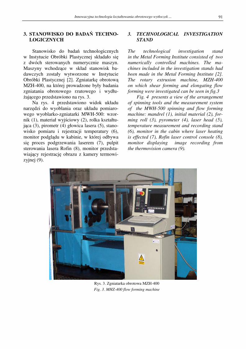
Stanowisko do badań technologicznych
w Instytucie Obróbki Plastycznej składało się z dwóch sterowanych numerycznie maszyn.
Maszyny wchodzące w skład stanowisk ba-
dawczych zostały wytworzone w Instytucie
Obróbki Plastycznej [2]. Zgniatarkę obrotową MZH-400, na której prowadzone były badania
zgniatania obrotowego rzutowego i wydłu-
Ŝającego przedstawiono na rys. 3.
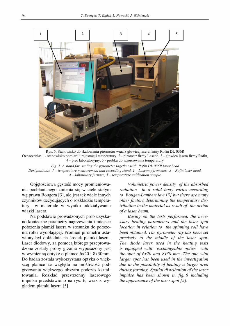
Na rys. 4 przedstawiono widok układu
narzędzi do wyoblania oraz układu pomiaro-
wego wyoblarko-zgniatarki MWH-500: wzor-
nik (1), materiał wyjściowy (2), rolka kształtu-
jąca (3), pirometr (4) głowica lasera (5), stano-
wisko pomiaru i rejestracji temperatury (6),
monitor podglądu w kabinie, w której odbywa
się proces podgrzewania laserem (7), pulpit
sterowania lasera Rofin (8), monitor przedsta-
wiający rejestrację obrazu z kamery termowi-
zyjnej (9).
3. TECHNOLOGICAL INVESTIGATION
STAND
The technological investigation stand
in the Metal Forming Institute consisted of two
numerically controlled machines. The ma-
chines included in the investigation stands had
been made in the Metal Forming Institute [2].
The rotary extrusion machine, MZH-400
on which shear forming and elongating flow
forming were investigated can be seen in fig.3
Fig. 4 presents a view of the arrangement
of spinning tools and the measurement system
of the MWH-500 spinning and flow forming
machine: mandrel (1), initial material (2), for-
ming roll (3), pyrometer (4), laser head (5),
temperature measurement and recording stand
(6), monitor in the cabin where laser heating
is effected (7), Rofin laser control console (8),
monitor displaying image recording from
the thermovision camera (9).
Rys. 3. Zgniatarka obrotowa MZH-400
Fig. 3. MHZ-400 flow forming machine

T. Drenger, T. Gądek, Ł. Nowacki, J. Wiśniewski
92
Rys. 4. Narzędzia do wyoblania wraz z urządzeniem laserowym do podgrzewania oraz układ pomiarowy
wyoblarko-zgniatarki MWH-500
Oznaczenia: 1 – wzornik, 2 – materiał wyjściowy, 3 – rolka kształtująca, 4 – pirometr, 5 – głowica lasera, 6 – stanowi-
sko pomiaru i rejestracji temperatury, 7 – monitor podglądu w kabinie, 8 – pulpit sterowania lasera Rofin, 9 - monitor
Fig. 4. Spinning tools together with the laser heating device and the measurement system of the MWH-500 spinning
and flow forming machine
Designations: 1 – mandrel, 2 – initial material, 3 – forming roll, 4 - pyrometer, 5 – laser head, 6 – temperature
measurement and recording stand, 7 - monitor in the cabinet, 8 - Rofin laser control console, 9 – monitor
4. METODYKA BADAŃ PODGRZEWA-NIA LASEREM I PRÓBY POMIARU TEMPERATURY
Jedną z podstawowych czynności niezbęd-
nych do rozpoczęcia prób podgrzewania lase-
rem było wyznaczenie współczynnika odbicia
R dla badanego materiału oraz ustalenie zdol-
ności absorpcyjnej A = 1-R wg odpowiednich
tablic [2,3,4,5,6]. Współczynnik emisyjności
do ustawienia pirometru przyjęto w wysokości
0,3 [7].
Wpływ na emisyjność i wartość współ-
czynnika emisyjności mają: rodzaj nagrzewa-
nego materiału, jakość powierzchni, stopień utlenienia powierzchni i dodatkowo czynnik
smarujący, który ma za zadanie zwiększenie
współczynnika absorpcji.
Pomiary temperatury przeprowadzono za
pomocą: • Termopary (w przypadku prób statycznych),
• Pirometru Standard ST-8855 infraRed&K-
Type o zakresie od -50 do 1370° C,
• Pirometru Marathon- MC1-C firmy Raytek
z plamką pomiarową około 1 mm [7],
4. LASER HEATING METHODOLOGY
AND TEMPERATURE MEASUREMENT
TESTS
One of the basic tasks necessary to start
the tests of laser heating was the determination
of the reflection coefficient, R, for the material
under examination and establishment of its
absorbing capacity, A = 1 –R, according to
the adequate tables [2, 3, 4, 5, 6]. The emissi-
vity factor of 0.3 has been adopted for setting
of the pyrometer [7].
The emissivity and emissivity factor are
influenced by: the kind of material being
heated, surface quality, the degree of surface
oxidation and, additionally, the lubricant
whose task is to increase the absorbing capa-
city.
The temperature measurements have been
performed by means of:
• A thermocouple ( in the case of static tests),
• A Standard ST-8855 infraRed&K-Type py-
rometer with the range of -50 up to 1370ºC,
• A Marathon- MC1-C pyrometer made
by Raytek, with a measurement spot of about
1 mm [7],
1
5 2 3 8 7 6 9 4
Innowacyjna technologia kształtowania obrotowego wytłoczek ...
93
• Pirometru firmy Lascon LPC 03 dedykowa-
nego do lasera Rofin z głowicą firmy La-
scon i plamką pomiarową około 1,5 mm
[10].
Termopara słuŜyła w niŜszych temperatu-
rach do porównania temperatur z pirometrem
standard-8855. Stosowanie jej ze względu na
podłączone przewody nie jest moŜliwe w przy-
padku obracającego się podgrzewanego obiek-
tu.
Pirometr Standard ST-8855 nie dawał wy-
ników oczekiwanych poniewaŜ plamka pomia-
rowa była zbyt duŜa, większa od strefy pod-
grzewanej. Ponadto pirometr musi być połoŜo-
ny bardzo blisko strefy pomiaru, a takie usta-
wienie utrudnia przebieg procesu i celność wiązki pirometru.
Pirometr firmy Raytek z plamką pomiaro-
wą 1mm jest urządzeniem dokładnym ale
w przypadku pomiarów statycznych. Przy prze-
mieszczaniu się wraz z głowicą lasera pirometr
nie nadąŜał z odczytem optymalnym tempera-
tur i wyniki nie były miarodajne.
Właściwym do badań temperatury okazał
się pirometr firmy Lascon LPC 03 dedykowany
do lasera Rofin z głowicą firmy Lascon i plam-
ką pomiarową około 1,5 mm. Pirometr ten da-
wał najbardziej powtarzalne wyniki, niemniej
jednak przed przystąpieniem do pomiaru piro-
metrem firmy Lascon z głowicą Rofin prze-
prowadzono wzorcowanie [10].
Wzorcowanie przeprowadzono przy pod-
łączeniu pirometru do głowicy laserowej
i obiektem obserwowanym, którym był piec
laboratoryjny z moŜliwością ustawiania precy-
zyjnego temperatury. Na rys. 5 przedstawiono
stanowisko do skalowania pirometru wraz
z głowicą lasera firmy Rofin DL 036R. Na ry-
sunku 5 oznaczono: stanowisko pomiaru i reje-
stracji temperatury (1), pirometr firmy Lascon
(2), głowica lasera firmy Rofin (3), piec labora-
toryjny (4), próbka do wzorcowania temperatu-
ry (5).
Na przedstawionym stanowisku wyskalo-
wano w temperaturze 700, 800, 900 i 1000 oC
pirometr wraz z głowicą laserową firmy Rofin
DL 036R i uzyskano błąd pomiaru w stosunku
do rzeczywistej temperatury mniejszy niŜ 2%.
• An LPC 03 pyrometer made by Lascon
dedicated to Rofin laser with a Lascon head
and the measurement spot of about 1.5 mm
[10].
The thermocouple, at lower temperatures,
served for comparing the temperatures to those
of the Standard-8855 pyrometer. Due to
the cables connected to it, the thermocouple
cannot be used if the heated object is rotating
The Standard ST-8855 pyrometer did not
render expected results because the measure-
ment spot was too large, larger than the heated
zone. What’s more, the pyrometer must be lo-
cated very near to the measurement zone,
which arrangement makes the process and
precise incidence of the pyrometer beam diffi-
cult.
Raytek pyrometer with its measurement
spot of 1 mm is a precise device but in the case
of static measurements. When moving together
with the laser head, the pyrometer could not
perform optimum temperature reading on time
and the results were not reliable.
The suitable device for temperature mea-
surement proved to be the LPC 03 pyrometer
dedicated to Rofin laser with Lascon head and
a measurement spot of about 1.5 mm. This py-
rometer rendered the most repeatable results,
nevertheless, calibration has been performed
prior to measurement with the Lascon pyrome-
ter with Rofin head [10].
Calibration has been performed with
the pyrometer connected to the laser head and
the observed object which was a laboratory
furnace with a possibility of accurate tempera-
ture setting. Fig. 5 presents a stand for py-
rometer scaling together with Rofin DL 036R
laser head. Designations: temperature mea-
surement and recording stand (1), Lascon py-
rometer (2), Rofin laser head (3), laboratory
furnace (4), a sample for temperature calibra-
tion (5).
In the stand being presented, the pyrome-
ter, together with Rofin DL 036R laser head
have been scaled at 700, 800, 900 and 1000 ºC
an error below 2% as compared to the true
temperature has been obtained.
T. Drenger, T. Gądek, Ł. Nowacki, J. Wiśniewski
94
Rys. 5. Stanowisko do skalowania pirometru wraz z głowicą lasera firmy Rofin DL 036R
Oznaczenia: 1 - stanowisko pomiaru i rejestracji temperatury, 2 - pirometr firmy Lascon, 3 - głowica lasera firmy Rofin,
4 - piec laboratoryjny, 5 - próbka do wzorcowania temperatury
Fig. 5. A stand for scaling the pyrometer together with Rofin DL 036R laser head
Designations: 1 – temperature measurement and recording stand, 2 – Lascon pyrometer, 3 – Rofin laser head,
4 – laboratory furnace, 5 – temperature calibration sample
Objętościowa gęstość mocy promieniowa-
nia pochłanianego zmienia się w ciele stałym
wg prawa Bougera [3], ale jest teŜ wiele innych
czynników decydujących o rozkładzie tempera-
tury w materiale w wyniku oddziaływania
wiązki lasera.
Na podstawie prowadzonych prób uzyska-
no konieczne parametry nagrzewania i miejsce
połoŜenia plamki lasera w stosunku do połoŜe-
nia rolki wyoblającej. Promień pirometru usta-
wiony był dokładnie na środek plamki lasera.
Laser diodowy, za pomocą którego przeprowa-
dzone zostały próby grzania wyposaŜony jest
w wymienną optykę o plamce 6x20 i 8x30mm.
Do badań została wykorzystana optyka o więk-
szej plamce ze względu na moŜliwość pod-
grzewania większego obszaru podczas kształ-
towania. Rozkład przestrzenny laserowego
impulsu przedstawiono na rys. 6, wraz z wy-
glądem plamki lasera [5].
Volumetric power density of the absorbed
radiation in a solid body varies according
to Bouger-Lambert law [3] but there are many
other factors determining the temperature dis-
tribution in the material as result of the action
of a laser beam.
Basing on the tests performed, the nece-
ssary heating parameters and the laser spot
location in relation to the spinning roll have
been obtained. The pyrometer ray has been set
precisely to the middle of the laser spot.
The diode laser used in the heating tests
is equipped with exchangeable optics with
the spot of 6x20 and 8x30 mm. The one with
larger spot has been used in the investigation
due to the possibility of heating a larger area
during forming. Spatial distribution of the laser
impulse has been shown in fig. 6 including
the appearance of the laser spot [5].
1 3 4 5 2

Innowacyjna technologia kształtowania obrotowego wytłoczek ...
95
Rys. 6. Rozkład przestrzenny natęŜenia impulsu laserowego(gaussowski) i wygląd plamki lasera [5]
Fig. 6. Spatial (Gaussian) distribution of the laser impulse intensity and the laser spot appearance [5]
Rys. 7. Głowica lasera uŜytego do badań podgrzewania przy kształtowaniu obrotowym stopu niklu Inconel 625 [5]
Oznaczenia: 1 – płyta podstawowa, 2 – stosy diod, 3 – homogenizer, 4 – urządzenie pomiaru mocy, 5 – oprawka
z soczewkami ogniskującymi
Fig. 7. The head of the laser used in the investigation of heating in rotary forming of Inconel 625 nickel alloy [5]
Designations: 1 – foundation plate, 2 – diode files, 3 – homogenizer, 4 – power measurement device, 5 – focusing lens
holder
W przypadku laserów diodowych duŜej mocy
podstawą całego urządzenia jest głowica lase-
rowa, która przedstawiona jest na rys. 7. Na
płycie podstawowej (1) umieszczone są stosy
diod (2). Światło ze stosów diod jest kierowane
poprzez homogenizer (3) i oprawkę z soczew-
kami ogniskującymi (5), która przedstawiona
jest na rys. 8. Moc lasera mierzona jest za po-
mocą urządzenia pomiaru mocy (4).
In the case of high power diode lasers, the es-
sential part of the whole device is the laser
head (to be seen in fig. 7). On the foundation
plate (1), files of diodes (2) are located. Light
from the diode files is directed, through
the homogenizer (3) and the holder with focus-
ing lenses (5) which is shown in fig. 8. The la-
ser power is measured by means of the power
measurement device (4).
1
4
5 3 2
T. Drenger, T. Gądek, Ł. Nowacki, J. Wiśniewski
96
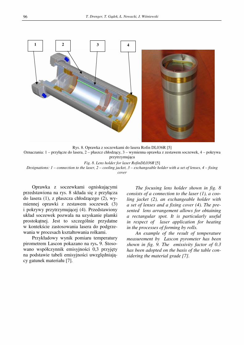
Rys. 8. Oprawka z soczewkami do lasera Rofin DL036R [5]
Oznaczania: 1 – przyłącze do lasera, 2 – płaszcz chłodzący, 3 – wymienna oprawka z zestawem soczewek, 4 – pokrywa
przytrzymująca
Fig. 8. Lens holder for laser RofinDL036R [5]
Designations: 1 – connection to the laser, 2 – cooling jacket, 3 – exchangeable holder with a set of lenses, 4 – fixing
cover
Oprawka z soczewkami ogniskującymi
przedstawiona na rys. 8 składa się z przyłącza
do lasera (1), z płaszcza chłodzącego (2), wy-
miennej oprawki z zestawem soczewek (3)
i pokrywy przytrzymującej (4). Przedstawiony
układ soczewek pozwala na uzyskanie plamki
prostokątnej. Jest to szczególnie przydatne
w kontekście zastosowania lasera do podgrze-
wania w procesach kształtowania rolkami.
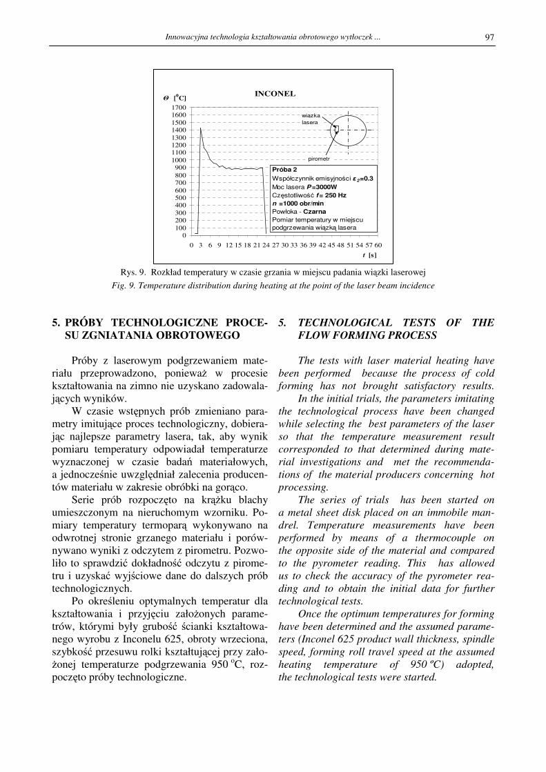
Przykładowy wynik pomiaru temperatury
pirometrem Lascon pokazano na rys. 9. Stoso-
wano współczynnik emisyjności 0,3 przyjęty
na podstawie tabeli emisyjności uwzględniają-cy gatunek materiału [7].
The focusing lens holder shown in fig. 8
consists of a connection to the laser (1), a coo-
ling jacket (2), an exchangeable holder with
a set of lenses and a fixing cover (4). The pre-
sented lens arrangement allows for obtaining
a rectangular spot. It is particularly useful
in respect of laser application for heating
in the processes of forming by rolls.
An example of the result of temperature
measurement by Lascon pyrometer has been
shown in fig. 9. The emissivity factor of 0.3
has been adopted on the basis of the table con-
sidering the material grade [7].
4 3 2 1
Innowacyjna technologia kształtowania obrotowego wytłoczek ...
97
Rys. 9. Rozkład temperatury w czasie grzania w miejscu padania wiązki laserowej
Fig. 9. Temperature distribution during heating at the point of the laser beam incidence
5. PRÓBY TECHNOLOGICZNE PROCE-SU ZGNIATANIA OBROTOWEGO
Próby z laserowym podgrzewaniem mate-
riału przeprowadzono, poniewaŜ w procesie
kształtowania na zimno nie uzyskano zadowala-
jących wyników.
W czasie wstępnych prób zmieniano para-
metry imitujące proces technologiczny, dobiera-
jąc najlepsze parametry lasera, tak, aby wynik
pomiaru temperatury odpowiadał temperaturze
wyznaczonej w czasie badań materiałowych,
a jednocześnie uwzględniał zalecenia producen-
tów materiału w zakresie obróbki na gorąco.
Serie prób rozpoczęto na krąŜku blachy
umieszczonym na nieruchomym wzorniku. Po-
miary temperatury termoparą wykonywano na
odwrotnej stronie grzanego materiału i porów-
nywano wyniki z odczytem z pirometru. Pozwo-
liło to sprawdzić dokładność odczytu z pirome-
tru i uzyskać wyjściowe dane do dalszych prób
technologicznych. Po określeniu optymalnych temperatur dla
kształtowania i przyjęciu załoŜonych parame-
trów, którymi były grubość ścianki kształtowa-
nego wyrobu z Inconelu 625, obroty wrzeciona,
szybkość przesuwu rolki kształtującej przy zało-
Ŝonej temperaturze podgrzewania 950 oC, roz-
poczęto próby technologiczne.
5. TECHNOLOGICAL TESTS OF THE
FLOW FORMING PROCESS
The tests with laser material heating have
been performed because the process of cold
forming has not brought satisfactory results.
In the initial trials, the parameters imitating
the technological process have been changed
while selecting the best parameters of the laser
so that the temperature measurement result
corresponded to that determined during mate-
rial investigations and met the recommenda-
tions of the material producers concerning hot
processing.
The series of trials has been started on
a metal sheet disk placed on an immobile man-
drel. Temperature measurements have been
performed by means of a thermocouple on
the opposite side of the material and compared
to the pyrometer reading. This has allowed
us to check the accuracy of the pyrometer rea-
ding and to obtain the initial data for further
technological tests.
Once the optimum temperatures for forming
have been determined and the assumed parame-
ters (Inconel 625 product wall thickness, spindle
speed, forming roll travel speed at the assumed
heating temperature of 950 ºC) adopted,
the technological tests were started.
INCONEL
0100
200300
400500600
700800
9001000
110012001300
14001500
16001700
0 3 6 9 12 15 18 21 24 27 30 33 36 39 42 45 48 51 54 57 60
t [s]
Θ [0C]
Próba 2
Współczynnik emisyjności ε 2=0.3
Moc lasera P=3000W
Częstotliwość f= 250 Hz
n =1000 obr/min
Powłoka - Czarna
Pomiar temperatury w miejscu
podgrzewania wiązką lasera
wiązka
lasera
pirometr
T. Drenger, T. Gądek, Ł. Nowacki, J. Wiśniewski
98
Schemat procesu kształtowania obrotowego,
wraz z podgrzewanym materiałem pokazano na
rysunku 10, gdzie: (1) krąŜek materiału, (2) do-
ciśnięty dociskaczem do wzornika w początko-
wej fazie podgrzewania materiału. Na krąŜku
materiału widać plamkę promienia laserowego
(3) i rolkę kształtującą (4).
Badania technologiczne prowadzone były
na dwóch stanowiskach badawczych pokaza-
nych na rys. 3 i 4. Ze względu na rozmiar pro-
wadzonych badań wyniki zgniatania obrotowe-
go wydłuŜającego będą przedstawione w innych
publikacjach. W niniejszym artykule przedsta-
wiono jedynie wyniki prób wyoblania i zgniata-
nia obrotowego rzutowego części stoŜkowych
uwaŜanych za najtrudniejsze do kształtowania.
Próby zgniatania obrotowego rzutowego
wytłoczki wykonano przy kącie pochylenia po-
bocznicy α = 45°. Kryterium uzyskania pozy-
tywnego wyniku było otrzymanie wytłoczki bez
pęknięć i rozwarstwień materiału, uzyskanie
załoŜonej grubości ścianki pobocznicy. Ocenia-
no takŜe stopień przylegania ścianki do wzorni-
ka. Określało to wielkość odspręŜynowania ma-
teriału po zgniataniu obrotowym rzutującym.
A diagram of the flow forming process,
together with the material being heated, has
been shown in fig. 10 where: (1) a disk of mate-
rial, (2) pressed by the holder to the mandrel
at the beginning of material heating. On the ma-
terial disk, the spot of the laser ray (3) and
the forming roll (4) can be seen.
The technological investigation has been
performed on two stands shown in figs 3 and 4.
Due to the size of the investigation being per-
formed, the results of elongating flow forming
will be presented in other publications. This
paper presents only the results of the tests
of spinning and shear forming of conical parts
which are considered to be the most difficult
to form.
The trials of drawpiece shear forming have
been performed with the side wall inclination
angle of α = 45º. The criterion of positive result
was obtaining of a drawpiece without cracks
and material delamination and the desired side
wall thickness. The degree of the wall adhesion
to the mandrel has also been assessed. This has
determined the magnitude of the material
springback after shear forming.
Rys. 10. Widok części roboczej stanowiska badawczego do badania procesu wyoblania z laserowym podgrzewaniem
Oznaczenia: 1 - krąŜek materiału, 2 - dociśnięty dociskaczem do wzornika w początkowej fazie podgrzewania
materiału, 3 - plamka promienia laserowego, 4 - rolka kształtującą
Fig. 10. A view of the working part of the stand for investigating the process of spinning with laser heating
Designations: 1 – material disk, 2 – pressed by the holder at the initial phase of material heating, 3 – laser beam spot,
4 – forming roll
1 2 3 4
Innowacyjna technologia kształtowania obrotowego wytłoczek ...
99
W przypadku materiału uŜytego do badań o grubości t0 = 2,3 mm wyniki uzyskano zgod-
nie z przyjętą zasadą:
t = t0 sinα
gdzie:
t - grubość materiału po zgniataniu obroto-
wym rzutowym,
t0 - grubość materiału wyjściowego,
α - połowa kąta rozwarcia stoŜka.
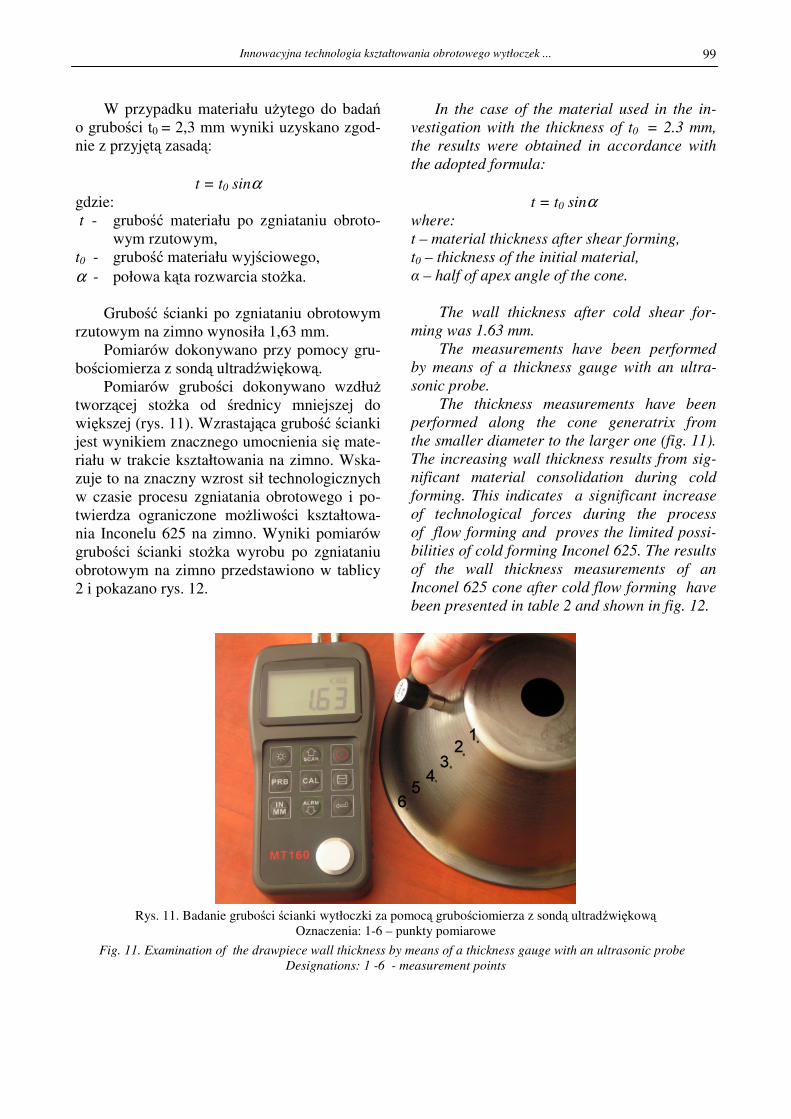
Grubość ścianki po zgniataniu obrotowym
rzutowym na zimno wynosiła 1,63 mm.
Pomiarów dokonywano przy pomocy gru-
bościomierza z sondą ultradźwiękową. Pomiarów grubości dokonywano wzdłuŜ tworzącej stoŜka od średnicy mniejszej do
większej (rys. 11). Wzrastająca grubość ścianki
jest wynikiem znacznego umocnienia się mate-
riału w trakcie kształtowania na zimno. Wska-
zuje to na znaczny wzrost sił technologicznych
w czasie procesu zgniatania obrotowego i po-
twierdza ograniczone moŜliwości kształtowa-
nia Inconelu 625 na zimno. Wyniki pomiarów
grubości ścianki stoŜka wyrobu po zgniataniu
obrotowym na zimno przedstawiono w tablicy
2 i pokazano rys. 12.
In the case of the material used in the in-
vestigation with the thickness of t0 = 2.3 mm,
the results were obtained in accordance with
the adopted formula:
t = t0 sinα
where:
t – material thickness after shear forming,
t0 – thickness of the initial material,
α – half of apex angle of the cone.
The wall thickness after cold shear for-
ming was 1.63 mm.
The measurements have been performed
by means of a thickness gauge with an ultra-
sonic probe.
The thickness measurements have been
performed along the cone generatrix from
the smaller diameter to the larger one (fig. 11).
The increasing wall thickness results from sig-
nificant material consolidation during cold
forming. This indicates a significant increase
of technological forces during the process
of flow forming and proves the limited possi-
bilities of cold forming Inconel 625. The results
of the wall thickness measurements of an
Inconel 625 cone after cold flow forming have
been presented in table 2 and shown in fig. 12.
Rys. 11. Badanie grubości ścianki wytłoczki za pomocą grubościomierza z sondą ultradźwiękową Oznaczenia: 1-6 – punkty pomiarowe
Fig. 11. Examination of the drawpiece wall thickness by means of a thickness gauge with an ultrasonic probe
Designations: 1 -6 - measurement points

T. Drenger, T. Gądek, Ł. Nowacki, J. Wiśniewski
100
Tablica 2. Wyniki pomiaru grubości ścianki stoŜka z Inconelu 625 po operacji zgniatania obrotowego
Table 2. The results of Inconel 625 cone wall thickness measurement after the operation of flow forming
Grubość ścianki stoŜka wyrobu po zgniataniu obrotowym na zimno (mm) Wall thickness of the product cone after cold flow forming (mm)
Numer próbki Sample number
Punkt pomiarowy Point
of measurement 1 2 3 4 5 6 7 8
1 1,63 1,02 1,63 1,65 1,65 1,58 1,57 1,63
2 1,62 1,2 1,62 1,61 1,65 1,63 1,64 1,68
3 1,62 1,62 1,62 1,63 1,67 1,68 1,69
4 1,63 1,62 1,68 1,65 1,68 1,68 1,7
5 1,6 1,65 1,72 1,68 1,68 1,69 1,7
6 1,73 1,69 1,73 1,68 1,69 1,7 1,71
uwagi notes
zerwanie na
krawędzi rolki rupture on the roll
edge
Pomiar grubości ścianki po zgniataniu obrotowym
1,45
1,5
1,55
1,6
1,65
1,7
1,75
1 2 3 4 5 6
Pomiar grubości ścianki od dna
Gru
bość ś
cia
nki
Próbka nr 1
Próbka nr 3
Próbka nr 4
Próbka nr 5
Próbka nr 6
Próbka nr 7
Próbka nr 8
Rys. 12. Zmiana grubości ścianki stoŜkowa wyrobu z materiału Inconel 625 po zgniataniu obrotowym na zimno
Fig. 12. The change of the Inconel 625 conical product wall thickness after cold flow forming
W przeglądzie literatury z zakresu kształ-
towania obrotowego blach [8] umieszczono
informację o miejscowym podgrzewaniu lase-
rowym przy kształtowaniu obrotowym blach.
W innej publikacji [9] opisano proces kształ-
towania obrotowego stoŜków ze stopu alumi-
nium w specjalnej kabinie, do której transpor-
towane jest gorące powietrze, które nagrzewa
materiał kształtowany i narzędzia. Za pomocą gorącego powietrza nie da się jednak podgrzać materiału do temperatury obróbki na gorąco.
The survey of literature concerning rotary
forming of sheet metal [8] contains information
on local laser heating in flow forming
of sheets. In another publication [9], the pro-
cess of flow forming of aluminium alloy cones
in a special cabinet to which hot air is supplied
to heat the material being formed and the tools.
Hot air, however, cannot heat the material up
to the temperature of hot forming. There is
a possibility to heat the roll working zone
by means of oxy-acetylene blowpipes.
1
3 4 5 6
7 8

Innowacyjna technologia kształtowania obrotowego wytłoczek ...
101
Istnieje jeszcze moŜliwość podgrzewania strefy
pracy rolek za pomocą palników acetylenowo
tlenowych. Obszar podgrzewania jest jednak
bardzo duŜy, a konstrukcja zespołu narzędzio-
wego maszyny do wyoblania jest skompliko-
wana.
W Instytucie Obróbki Plastycznej w mi-
nionych latach wykonano maszynę dla Premy
Milmet Sosnowiec, do obciskania na gorąco
szyjek butli wysokociśnieniowych. Natomiast
w roku 2009 w Instytucie podjęto nowe bada-
nia technologii kształtowania obrotowego
z podgrzewaniem laserowym.
Na rys. 13 przedstawiono próbkę po pierw-
szym zabiegu wyoblania z podgrzewaniem
laserowym materiału wyjściowego ze stopu
Inconel 625. W badaniach tych wykorzystano
optymalne parametry kinematyczne i geometrię rolki uzyskane w procesie zgniatania obroto-
wego rzutowego na zimno.
W tablicy 3 przedstawiono wyniki pomia-
rów kształtu wytłoczki ze stopu Inconel 625
przedstawionej na rys. 11. W tablicy podano
równieŜ zastosowane parametry maszyny, przy
których wytłoczka była wykonywana. Kształ-
towanie odbywało się z miejscowym podgrze-
waniem laserowym materiału podczas wyobla-
nia.
Parametry technologiczne zarówno urzą-dzenia laserowego, jaki i wyoblarki sterowanej
numerycznie zostały dobrane doświadczalnie.
Na podstawie dotychczasowych badań procesu wyoblania zrealizowanych w ramach
prac statutowych opracowano przykładową trajektorię sterowania rolką wg schematu poka-
zanego na rys. 14.
However, the heating area is very large and
the design of the spinning machine tool set
is complex.
In the past years, a machine for hot
crimping of high pressure bottle necks for
Prema Milmet Sosnowiec has been made
in the Metal Forming Institute. In 2009,
the Institute has undertaken new investigation
of rotary forming with laser heating.
Fig. 13 shows a sample after the first ope-
ration spinning with laser heating of Inconel
625 initial material. In that investigation,
the optimum kinematic parameters and roll
geometry obtained in the process of cold shear
forming have been used.
Table 4 presents the results of measure-
ments of the Inconel 625 drawpiece shown
in fig. 11. The table shows also the machine
parameters applied with which the drawpiece
has been made. Forming has been effected with
local laser heating of the material during spi-
nning.
Both the technological parameters
of the laser device and those of the numerically
controlled spinning machine have been
experimentally selected.
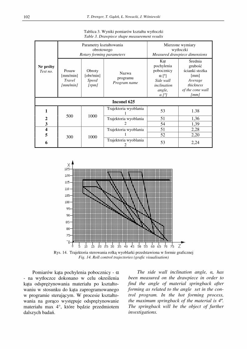
Basing on the spinning process investiga-
tion performed so fat within the statute works,
roll control trajectories have been elaborated
according to the scheme shown in fig. 14.
Rys. 13. Próbka po pierwszym zabiegu wyoblania z podgrzewaniem laserowym
Fig. 13. A sample after the first operation of spinning with laser heating
T. Drenger, T. Gądek, Ł. Nowacki, J. Wiśniewski
102
Tablica 3. Wyniki pomiarów kształtu wytłoczki
Table 3. Drawpiece shape measurement results
Parametry kształtowania
obrotowego
Rotary forming parameters
Mierzone wymiary
wytłoczki
Measured drawpiece dimensions
Nr próby Test no. Posuw
[mm/min]
Travel
[mm/min]
Obroty
[obr/min]
Speed
[rpm]
Nazwa
programu
Program name
Kąt pochylenia
pobocznicy
α [º]
Side wall
inclination
angle,
α [º]
Średnia
grubość ścianki stoŜka
[mm]
Average
thickness
of the cone wall
[mm]
Inconel 625
1 Trajektoria wyoblania
1 53 1.38
2 51 1,36
3
500 1000 Trajektoria wyoblania
2 54 1,39
4 51 2,28
5 Trajektoria wyoblania
1 52 2,20
6 300 1000
Trajektoria wyoblania
2 53 2,24
Rys. 14. Trajektoria sterowania rolką wyoblarki przedstawiona w formie graficznej
Fig. 14. Roll control trajectories (grafic visualisation)
Pomiarów kąta pochylenia pobocznicy - α
- na wytłoczce dokonano w celu określenia
kąta odspręŜynowania materiału po kształto-
waniu w stosunku do kąta zaprogramowanego
w programie sterującym. W procesie kształto-
wania na gorąco występuje odspręŜynowanie
materiału max 4°, które będzie przedmiotem
dalszych badań.
The side wall inclination angle, α, has
been measured on the drawpiece in order to
find the angle of material springback after
forming as related to the angle set in the con-
trol program. In the hot forming process,
the maximum springback of the material is 4º.
The springback will be the object of further
investigations.

Innowacyjna technologia kształtowania obrotowego wytłoczek ...
103
6. PODSUMOWANIE • Wstępne wyniki badań kształtowania obro-
towego z podgrzewaniem laserem nadstopu
niklu Inconel 625 wykazują moŜliwość za-
stosowania lasera Rofin DL036R do pod-
grzewania materiału w procesie kształtowa-
nia obrotowego.
• Ze względu na miejscowy kontakt narzędzi
w czasie wyoblania i zgniatania obrotowego
zastosowanie technologii kształtowania rol-
kami daje moŜliwość uzyskania większych
odkształceń niŜ przy tłoczeniu.
• W wyniku prowadzonych badań uzyskano
wyroby próbne o odkształceniach mniej-
szych niŜ w przypadku kształtowania po-
równywalnych materiałów ze stali nie-
rdzewnej austenitycznej i stali Ŝaroodpor-
nych.
• Przewiduje się wykonanie kolejnej serii
badań procesu wyoblania z podgrzewaniem
laserem dla wyrobów stosowanych w prze-
myśle lotniczym.
• Wyniki tych badań będą podstawą do za-
projektowania i wykonania nowych specja-
listycznych maszyn do kształtowania okre-
ślonych wyrobów. Będą to maszyny o zwar-
tej budowie, z chłodzonymi narzędziami,
wyposaŜone w osłony przed promieniowa-
niem laserowym i rozproszonymi promie-
niami odbitymi.
Praca realizowana w ramach projektu rozwo-
jowego nr R 1502703 pt.: „Technologia kształ-
towania plastycznego części silników lotni-
czych z nadstopu niklu z zastosowaniem zgnia-
tania obrotowego i wyoblania”.
6. SUMMARY
• The initial results of investigation of rotary
forming with laser heating of Inconel 625
nickel superalloy indicate the possibility
of using the Rofin DL036R laser for mate-
rial heating in the process of rotary forming.
• Due to the local contact of the tools during
spinning and flow forming, the application
of the technology of forming by rolls makes
it possible to obtain larger deformations
than in stamping
• As result of the investigation performed test
products with smaller strains than
in the case of forming comparable mate-
rials of stainless austenitic steel and heat-
resisting steels
• A further series of investigations
of the process of spinning with laser heating
for products used in the aerospace industry
is intended
• The results of those investigations will
be a basis for the design and execution
of new special machines for forming definite
products. Those will be machines of com-
pact construction, with cooled tools, pro-
vided with shields against laser radiation
and dispersed reflected rays.
The work is carried on within the development
project no. R 1502703 entitled: “ The techno-
logy of plastic forming of aerospace engine
parts of nickel superalloy with the application
of flow forming and spinning”.
LITERATURA/REFERENCES
[1] Pakieła Z., Lewandowska M., Molak R.: Charakterystyka nadstopu niklu Inconel 625 w zakresie struktury i wła-
ściwości mechanicznych. Raport nr 1/2008 Etap 1. Politechnika Warszawska s. 36.
[2] Raport roczny z projektu nr R1502703: Technologia kształtowania plastycznego części silników lotniczych
z nadstopów niklu z zastosowaniem procesów zgniatania obrotowego i wyoblania. Poznań 2010 s. 30.
[3] Jewtuszenko A., Matysiak S.J., RoŜniakowska M.: Temperatura i napręŜenia termiczne spowodowane oddziały-
waniem laserowym na materiały konstrukcyjne. Oficyna Wydawnicza Politechniki Białostockiej Białystok 2009.
[4] Ziętek B.: Lasery. Wydawnictwo naukowe Uniwersytetu Mikołaja Kopernika wydanie II Toruń 2009.
[5] Rofin DL 036 R, Oryginalna Instrukcja Obsługi, Hamburg 2008, s.140.
[6] Jankowiak M., Przystacki D.: Raport z badań wstępnych pomiaru temperatury, Poznań 2008, s. 13.
[7] Table of total emissivity firmy Monarchinstrument www.monarchinstrument.com.
[8] Music O., Allwood J.M., Kawai K.: A review of mechanics of metal spinning. Jurnal of Materials Processing
Technology 210 (2010) p. 3-23.

T. Drenger, T. Gądek, Ł. Nowacki, J. Wiśniewski
104
[9] Ken-ichro Mori, Minoru Ishiguro, Yuta Isomura: Hot sher spinning of cost aluminium alloy parts. Journal of Ma-
terials Processing Technology 209 (2009), p. 3621-3627.
[10] Lascon Manuals for Software and Hardware, Oryginalna Instrukcja Obsługi, Germany 2009, s. 74.