Embed Size (px)
Citation preview

Installation Manual
For SolaDeck Models 0783-41 and 0786-41
Table of Contents:
Warranty ………………………………………………………………………..2
SolaDeck Mounting instructions ……………………………………………..3
Safety Instructions, General Wiring…………………………………………..4
Requirements …………………………………………………………………..5
SolaDeck Features …………………………………………………………….6
Base Centering dimples……………………………….……………………….7
Base Plate Configuration ……………………………………………………...7
Fuse Holder and Bus …..…..………….……………………………………....8
Installed Equipment Examples 0783-41 & 0786-41……………..……………9
PV Panel Wiring Example……………………………………………………10
First Edition - February 2009
RSTC Enterprises Inc2219 Heimstead RoadEau Claire, Wi 54703866-367-7782
1

Warranty Information:
Thank you for your purchase. As with all manufactured devices repairs may be needed due to damage, unauthorized use, or defect.
• Warranty repairs must conform to warranty terms.• Equipment must be installed according to the instructions and manuals provided.• Products returned, must be Packaged, properly addressed and shipped prepaid.• There is no additional allowance or reimbursement for installer or user labor or travel time
required to disconnect, service or reinstall the damaged component(s).• RSTC will ship a replacement product prepaid to addresses in the continental United
States.• In the event of a product malfunction, RSTC will not bear any responsibility for resulting
losses, expenses, or damage to other components.
DO NOT PROCEED WITH INSTALLATION UNTIL YOU HAVE READENTIRE INSTRUCTIONS INCLUDING WARNINGS
2
One Year Limited WarrantyImportant: Evidence of original purchase is required forwarranty service.WARRANTOR: RSTC Enterprises IncorporatedELEMENTS OF WARRANTY: RSTC warrants for one year to the original retail owner, this SolaDeck is free from defects in materials and craftsmanship with only the limitations or exclusions set out below.WHAT IS NOT COVERED: This warranty covers only defects in materials and workmanship provided by RSTC Enterprises, and does not cover equipment damage or malfunction from misuse, abuse, accident, and act of God. Installation must be in accordance with our written instructions. RSTC Enterprises will not be liable for any installation charges associated with replacement , incidental or consequential damages resulting from your use of or inability to use the SolaDeck.REMEDY: Your only remedy under this warranty is theexchange or replacement in the event that the product does not conform to this warranty. This warranty gives you specific legal rights, and you may also have other rights, which vary from state to state.CLAIMS PROCESS: To make a claim under this warranty, the product should be shipped postage paid, with original purchase receipt to:
RSTC ENTERPRISES2219 HEIMSTEAD ROADEAU CLAIRE, WI 54703
1-866-367-7782 or www.commdeck.commpo
WARNING! STOPDO NOT WORK ON ROOF IF SURFACE IS WET, FROSTED, ICE OR SNOW COVERED.USE LADDERS SAFELYUSE HAND & EYE PROTECTION WHEN WORKING WITH POWER TOOLSUSE EXTREME CAUTION TO AVOID CONTACT WITH POWER LINES. CONTACT WITH POWER LINES, ELECTRIC LIGHTS OR POWER CIRCUITS MAY BE FATAL
Installation of this product should be attempted only by individuals skilled in the use of the tools and equipment necessary for installation. Protect you and all persons and property during installation. If you have any doubt concerning your competence or expertise, consult a qualified expert to perform the installation.R.S.T.C. Enterprises Incorporated assumes no responsibilityfor the failure of an architect, contractor, installer, or building owner to comply with all applicable laws, building codes and requirements, and adequate safety precautions.
Tools and Hardware ListUtility Knife - #2 Phillips Head Driver Bit- Pry Bar – Roof sealant – Cordless Drill
A – (7) # 10 – 1” Phillips head wood screws D – (2) 10-32 – ½” Steel studsB – (4) 8-32 – ½” Phillips head threading machine screws E – (2) # 10 Star washers C – (4) #10 Bonded seal washers F – (2) 10-32 – 3/8” steel nuts
3

IMPORTANT SAFETY INSTRUCTIONSSAVE THESE INSTRUCTIONS- This manual contains important instructions for models 0783-41 and 0786-41that shall be followed during installation of the combiner.
SolaDeck models are listed by ETL as PV Combiners under the standard:
UL 1741, First Edition
SolaDeck models meet UL 50 Type 3R rainproof requirements.
This enclosure is rated for up to 600 VDC fuses.
Grounding Instructions- Each system should be connected to a grounded,permanent wiring system. All system wiring and system grounding must comply with NEC Code, ANSI/NFPA 70-1996, or other appropriate codes, is the responsibility of the installer.
The equipment ground on SolaDeck is marked with the symbol:
Note: Solar panels produce electrical current when lighting is present, even during overcast weather. Do not wire from the array to the SolaDeck combiner. Complete all connections inside the SolaDeck combiner first and then connect the array.
General Wiring Installation Instructions• Remove any necessary knockouts before securing the SolaDeck to the roof or other
surface. • Follow the mounting instructions page 3• Slide the fuse holders onto the Din rail and lock in place.• Secure the Bus Bar to the fuse holders.• Install the negative power distribution block using the steel studs in the location
designated for the Negative PV Model (0783).• Install negative terminal blocks on DIN rail where designated PV Negative and lock in
place. Model (0786).• Connect all wires to fuse holders, bus bar lug and negative terminals, securing them
according to the listed torque values from table on page 5.• Conduit and Strain relief fittings and hubs must comply with UL 514B
4

Requirements
• Use minimum 75 C copper • Use only code approved, appropriately listed fuse holders and Fuses
Maximum Fuse Rating 30 AMP , 600 Volt
Total Maximum Current Rating 0783-41 / 0786-41 120 AMPS DC
Maximum Fuse Short Circuit Current 10ka
Fuse Holder Torque 13.6 in lb Flat or Phillips Head Driver
Din Rail Mounted Terminal Block Torque 9 - 14 in lb Flat Head Driver
Torque Data* for Box Lug
Wire Size Torque
AWG mm2 in lbs Nm
14-10 2.1-5.3 35 4
8 8.4 40 4.5
6-4 13.3-21.2 45 5.1
2 13.3-21.2 50 5.7
Torque Data* for Negative Power Distribution Block
Wire Size Torque
Screw DriverExternal Drive
Wrench
AWG mm2 in lbs Nm
14-10 2.1-5.3 35 75 4
8 8.4 40 75 4.5
6-4 13.3-21.2 45 110 5.1
Main 2/0-14 13.3-21.2 0 120 5.7
Torque Data* for Ground Lug
Wire Size Torque
AWG mm2 in lbs Nm
14-10 2.1-5.3 35 4
8 8.4 40 4.5
6-4 13.3-21.2 45 5.1
2-2/0 13.3-21.2 50 5.7
5

SolaDeck Combiner Features
• Stamped Seamless Galvanized Steel• Powder Coated Surfaces• Mounting Hardware Included• Flashes into the roof deck• 6” DIN rail installed Model (0786)• 3” DIN rail installed Model (0783)• 2 Position Ground lug installed• 3 Roof deck knockouts .5”, .75”, 1”• 5 Centering dimples for enter/exit strain or conduit fittings • Accommodates fuse holders with combiner bus
SolaDeck cover on base Fig 1Four 8-32 3/8” phillips head self thread screws and boded seal washers secure the SolaDeck cover
Figure 1
6
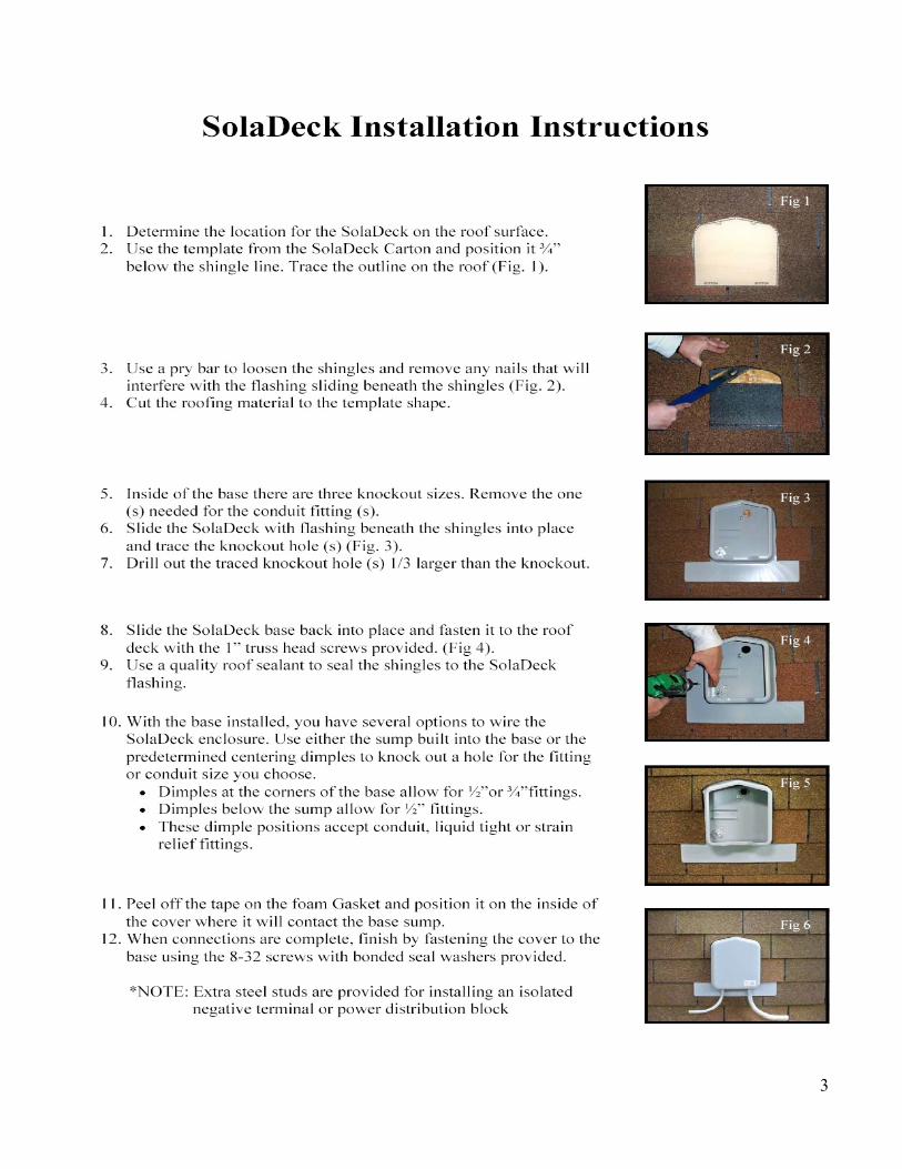
SolaDeck Base showing dimples Fig 2Corner dimples support .5” or .75” fittings or conduitCenter dimples support .5” fittings or conduit
Figure 2
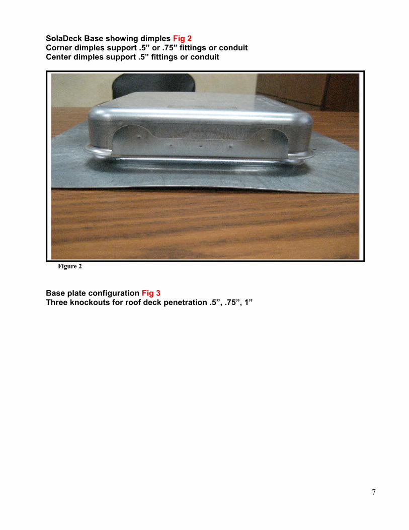
Base plate configuration Fig 3Three knockouts for roof deck penetration .5”, .75”, 1”
7
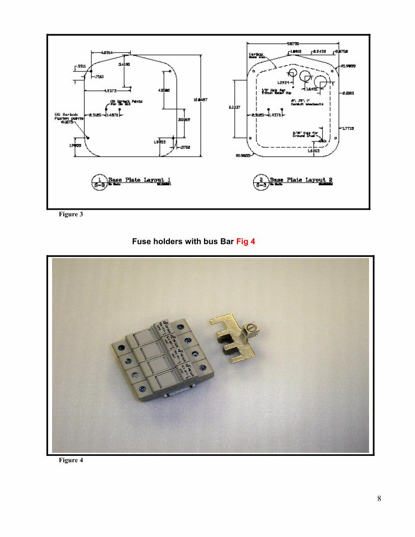
Figure 3
Fuse holders with bus Bar Fig 4
Figure 4
8

SolaDeck Models with cover off
Model 0786-41
9

Model 0783-41
PV Panel Example
10