Embed Size (px)
Citation preview

Comparative Design of intze tank by Membrane Design and Continuity Analysis
Civil Engineering departmentLaxmi institute of technology,sarigam
Guided By:- PREPARED BY :-Mr. Arif A. Memon
BHANUSHALI JAYESHKUMAR R.YADAV MUKESHKUMAR D.
Mishra Bipinkumar R.Dudhani Pathik V.

Content Introduction Water Tank General & Design Requirement of Liquid retaining structures Method of Analysis Theoretical Background of Membrane Design Design of Intze Tank By Membrane Design Theoretical Background of Continuity Analysis Design of Intze Tank By Continuity Analysis Comparison Conclusion
Water tanks are very important components of lifeline. They are critical elements in municipal water supply, fire fighting systems and in many industrial facilities for storage of water.
Usage of water tanks A reinforcement concrete tank is a very useful structure which is meant for the
storage of water, for swimming bath, sewage sedimentation and for such similar purposes.
Reinforced concrete overhead water tanks are used to store and supply safe drinking water.
INTRODUCTION

SOURCES OF WATER SUPPLY various sources of water can be classified into two categories:
Surface sources1) Ponds and lakes2) Streams and rivers 3) Storage reservoirs4) Oceans
Sub-surface sources1) Springs2) Infiltration wells3) Wells and tube-wells

In recent years there has been much emphasis on water supply projects all over the world, which are very essential for the social and industrial development of the country.
Classification based on heads:1. Tanks resting on ground
2. Elevated tanks supported on staging
3. Underground tanks
WATER TANKS

Various types of elevated tanks having different shapes
1) Circular tanks 2) Rectangular tanks

3) Spherical tanks 4) Circular tanks with conical bottom

For large storage capacity overhead tanks, circular tanks are found economical. However, In the flat bottom, the thickness and reinforcement is found to be heavy.
In the domed bottom, though the thickness and reinforcement in dome is normal, the reinforcement in the ring beam is excessive .
Intze tank

MAIN ADVANTAGES OF INTZE TANK
• The main advantages of such tank are that the outward thrust from top of conical part is resisted by ring beam B3.

Impervious floor. Minimum strength of cement. Water cement ratio. Tensile stresses. Cracking.
General & Design Requirement of Liquid retaining structures

Basic design requirement for liquid retaining structures as per IS 3370 are as follows:Water tanks are design as uncorrected section to design is we
have to restrict the concrete and steel stresses.
Grade of concrete Permissible stress in tension shear
N/mm2
(tv)
Direct(σct) Bending(σcbt)
M15 1.1 1.5 1.5
M20 1.2 1.7 1.7
M25 1.3 1.8 1.9
M30 1.5 2.0 2.2
M35 1.6 2.2 2.5
M40 1.7 2.4 2.7

Permissible stresses in steel For resistance to cracking When steel and concrete are assumed to act together for checking the tensile stress in concrete for avoidance of crack, the tensile stress in steel will be limited by the requirement that the permissible tensile stress in the concrete is not exceeded so the tensile stress in steel shall be equal to the product of modular ratio of steel and concrete, and the corresponding allowable tensile stress in concrete.
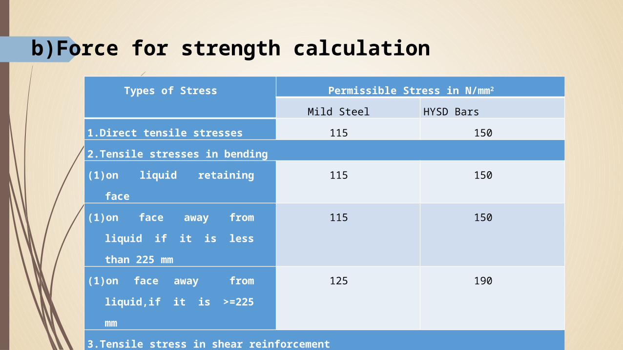
Types of Stress Permissible Stress in N/mm2
Mild Steel HYSD Bars1.Direct tensile stresses 115 1502.Tensile stresses in bending(1) on liquid retaining face 115 150(1) on face away from liquid if it is
less than 225 mm115 150
(1) on face away from liquid,if it is >=225 mm
125 190
3.Tensile stress in shear reinforcement(1) For Member less than 225 thick 115 150
(1) For members >= 225 mm thick 125 175
4. Compressive Stress in columns subjected to direct load
125 175
b)Force for strength calculation

METHOD OF ANALYSIS The analysis of shell structures involves a two steps procedure similar to well-
known two step operation used in analysing statically indeterminate frames.
The first step is to make imaginary cut at the junction and assume the imaginary supports condition consistence with the membrane analogy. This assumption permits the determination of membrane forces and deformation due to different loading condition.
The second step is to apply restraining forces at the edges consistent with the actual support condition to make the deformation compatible at the junction.

Analysis of roof wall joint The roof may be designed as a spherical or conical dome.

Analysis of the spherical bottom conical wall joint
The joint may either be supported on columns or on a circular shaft.
If the tank is supported on columns, the two shells are connected through a ring beam to the columns and, if the tank is supported on a circular shaft, the threw shells can be jointed together without a ring beam.

In the membrane analysis the member are assumed to act independent of the others. Hence individually all components of the structure are designed.
. The member are therefore subjected to only direct stresses and as the joints are not considered rigid i.e. as all members are acting individual bending moment is not introduced.
Fig shows the deflected shape of water tank. The firmed lines show the undeflected shape of tank.
Theoretical Background of the Membrane Design

Figure shows the deflected shape of water tank. The firmed lines show the undefeated shape of tank
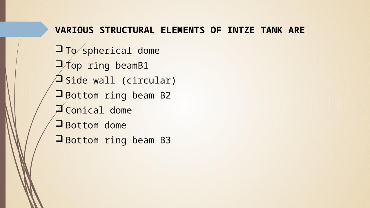
VARIOUS STRUCTURAL ELEMENTS OF INTZE TANK ARE
To spherical dome Top ring beamB1 Side wall (circular) Bottom ring beam B2 Conical dome Bottom dome Bottom ring beam B3

Top Spherical Dome
Meridional thrust is maximum at support.
Hoop force is maximum at crown.
Radial bars are provided for meridional thrust.
Circular hoops are provided for circumferential force.

Top Rings Beam B1 The meridional thrust T1, of the top dome at the level of top rings beam B1 has
two components, viz. vertical component and horizontal component . The beam is supported vertically throughout by side circular wall. Thus the
vertical component which is nothing but the downward load (DD+LL) of the dome gets transferred through side circular wall.
The horizontal component includes hoop tension in beam for which the beam shall be designed.

Side Walls (circular) The side circular wall,
assumed as free to move at top and bottom, is subjected to hoop tension due to water load.
The hoop tension increases with the depth.
Thickness of the wall is designed for maximum hoop tension at level of and may be reduced with reduction of hoop tension refer fig.

Bottom Ring Beam B2 The vertical load acting on ring beam consists of load from top
dome, top ring beam , side wall and self-weight of beam This load gets transferred to the conical dome by thrust T in the
conical dome

Conical Dome The conical dome is subjected to both meridional thrust as well as
hoop tension. Meridional thrust: The meridional thrust in the conical dome is
due to vertical forces (weights) transferred to it at its base. The total load consists of Weight of top dome, cylindrical wall etc. Weight of water Self-weight

Hoop tension:- Due to water pressure and self-weight, the conical dome will be subjected to hoop tension.

Bottom dome Bottom dome develops compressive stresses both meridional as
well as along hoops, due to weight of water supported by it and also due to its own weight.
Bottom Ring Beam The ring beam receives an inward inclined thrust from the conical
dome and an outward thrust from the bottom dome.

Theoretical Background of Continuity Analysis The pure membrane state of stresses will exist so long as each cell is
simply supported at its edges, that is, it is able to undergo resulting edge displacements without restraint, while the supports supply the necessary reaction to balance the meridional forces .
This is however not possible in practice and the edge displacement are actually restrained. This gives rise to secondary stresses in the form of edge moments and the hoop stresses. It will be clear by examining the deflected shape of each part of intze tank in figure
Hence in continuity analysis, the calculation should consist the framing of the equation of consistency of deformation and thus finding the continuity effect.
Link

Deflected Shape By Continuity Analysis

Comparison Force and Bending moment for 9lakh
Component Membrane design Continuity Analysis
Hoop force(N/m) B.M.(N-m/m) Hoop force B.M(N-m)
Top Dome 19900 0 41931 -2035.06
Top Beam 189710 0 60380 -8.257426169
Wall @ 0 104827 2043.32
Wall @ base 343000 0 299301 -4743.546328
Middle Beam 604452 0 718323 -414.1410042
Conical dome(Top) 555070.6 0 478882 4457.687332
Conical dome(bottom) 535070.6 0 98463 53634.45591
Bottom Dome 0 61539 -35559.58233
Circular girder 0 576680 68659.7894 49178.49426

Area of reinforcement for 9lakh
Component Membrane Design Continuity Analysis
Hoop steel Moment steel Hoop steel Moment steel
Top Dome 300 0 280 194
Top Beam 1265 0 703 negligible
Wall @ mid height 1372 0 699
Wall @ base 2512 0 1995 7895
Middle Beam 4030 0 4789 negligible
Conical dome(Top) 3700 0 3193 7895
Conical dome(bottom) 3700 0 656 1077
Bottom Dome 515 0 1179
Circular girder 0 3825.03 0 4280

Force and Bending moment for 6 lakh
Component Membrane design Continuity Analysis
Hoop force(N/m) B.M.(N-m/m) Hoop force B.M(N-m)
Top Dome 9780 0 32670 -1390.64
Top Beam 106660 0 29403 0.490932371
Wall @ 0 73507 1390.15
Wall @ base 300000 0 228234 -1479.4282
Middle Beam 492200 0 608623 -627.8556201
Conical dome(Top) 484260 0 405749 1407.28382
Conical dome(bottom) 435976 0 5570 58805.02094
Bottom Dome 0 3481 -22363.89169
Circular girder 0 352490 179699.265 37944.95813

Area of reinforcement for 6 lakh
Component Membrane Design Continuity Analysis
Hoop steel Moment steel Hoop steel Moment steel
Top Dome 240 0 218 133
Top Beam 711 0 433 negligible
Wall @ mid height 1200 0 490
Wall @ base 2055 0 1522 2493
Middle Beam 3281 0 4057 negligible
Conical dome(Top) 3228 0 2705 2493
Conical dome(bottom) 3228 0 37 1180
Bottom Dome 515 0 742
Circular girder 0 2343.37 0 3530

Force and Bending moment for 12 lakh
Component Membrane design Continuity Analysis
Hoop force(N/m) B.M.(N-m/m) Hoop force B.M(N-m)
Top Dome 16340 0 33160 -1540.94
Top Beam 170340 0 53056 17.01389229
Wall @ 0 107771 1523.93
Wall @ base 490000 0 451763 -6675.515139
Middle Beam 883400 0 834025 24.21766469
Conical dome(Top) 762958 0 556016 5951.297474
Conical dome(bottom) 686390 0 115128 70710.7457
Bottom Dome 0 71955 -45505.65092
Circular girder 0 760700 105724.418 62590.82336
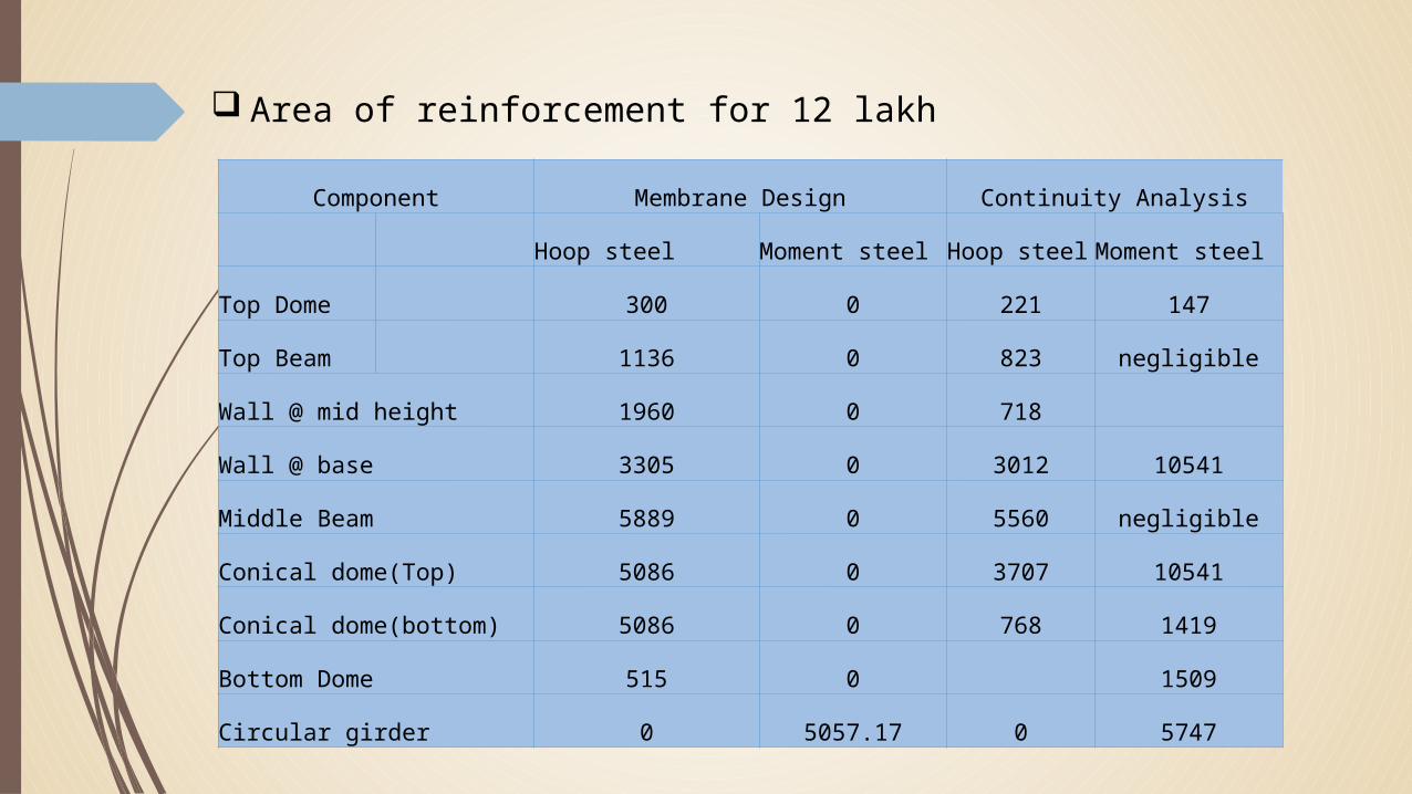
Area of reinforcement for 12 lakh
Component Membrane Design Continuity Analysis
Hoop steel Moment steel Hoop steel Moment steel
Top Dome 300 0 221 147
Top Beam 1136 0 823 negligible
Wall @ mid height 1960 0 718
Wall @ base 3305 0 3012 10541
Middle Beam 5889 0 5560 negligible
Conical dome(Top) 5086 0 3707 10541
Conical dome(bottom) 5086 0 768 1419
Bottom Dome 515 0 1509
Circular girder 0 5057.17 0 5747

Conclusion The above summary shows that, the effect of continuity leads to 9%
increase of reinforcement compare to membrane design. However, widely used method is membrane design as this continuity analysis can be considered more important for more capacity of tanks. For less capacity, it leads to minor difference. For this capacity as for 9 lakhs litres, continuity analysis leads to more reinforcement and hence design done by continuity should be adopted and if membrane design is adopted, chances for error by comparing with membrane increase by 9%.

Thank You…

Any Question???