Embed Size (px)
Citation preview
1
INSTALLATION INSTRUCTIONS FOR
JEROL
Posts & Columns
2
Contents
(1) Foundations
1.1 Excavation
(2) Lighting Columns
2.1 Assembly
2.2 Electrical Connection
(3) Sign & Signal Posts – Illuminated
3.1 Assembly
3.2 Sign Plate
3.3 Signal Head
3.4 Electrical Connection
(4) Sign Posts – Non Illuminated
4.1 Assembly
(5) Cast In-Situ Foundations
5.1 Excavation
5.2 Assembly
5.3 Sign Plate
(6) Health & Safety Advice
(7) Treatment After Cutting
(8) Fig 1, 2 & 3. Installation drawings
(9) Installation photographs
3
(1) METHOD STATEMENT FOR INSTALLATION OF
JEROL PRE CAST FOUNDATION
1.1 Excavation and foundation
• Excavate a hole of appropriate depth and sufficient diameter to give a clearance of
500mm all round the foundation, to allow space for mechanical consolidation of thebackfill.
Notes:
a) When considering depth, note that the top of the foundation must be a minimum of100mm below ground level.
b) If an auger is used to drill a hole with less clearance, see special comments aboutbackfill below.
• Lift the pre-cast foundation by passing a sling down the centre of the foundation and
securing with a bar outside the cable entry hole.
• Lower the foundation into the excavation and level as necessary.
• Backfill must be the excavated material or better quality material.(Type 1 Sub-baserecommended))
If Electrical Connection required
• First backfill in layers of 150 mm, compacting each layer, up to the bottom of the
cable entry hole.
• Excavate as necessary to install the access chamber and cable duct from chamber tocable entry. The chamber should be 500 mm from the edge of the foundation, so as
to not compromise the stability of the foundation.
• See notes below on specific cable installation
• Backfill and compact the complete excavation in layers up to the securing screw
holes, using the Type 1 sub-base material.• Insert the rubber foundation cover
• Complete the installation by replacing the excavated material to 100mm above the
top of the foundation. Compact as above.
Note: If an auger has been used to drill a hole with small clearance to the
foundation, it will not be possible to use layered and compacted fill. In this
case backfill should be concrete, vibrated to ensure there are no voids,but the grade is not important, as the use of concrete is simply a means
to ensure adequate backfill.
4
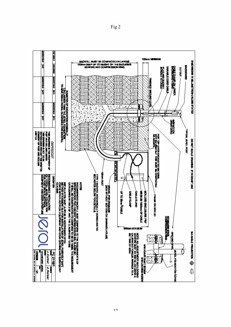
(2) METHOD STATEMENT FOR INSTALLATION OF JEROL LIGHTING COLUMNIN JEROL FOUNDATION
This method statement should be used in conjunction with the recommended electricalconnection as shown in Figure 2. It uses a suitable plug and socket bonded onto a suitable 3 corecable, with 1.5m length on the plug and at least 4m length on the socket. This cable can be jointed toa 3-phase or single-phase highway distribution cable, using an IP67 junction box located in anadjacent access chamber.
2.1 Assembly and installation of column
Note: The cable from base compartment to luminaire position can be installed during the
assembly, and taped to the end of the bracket arm.• Assemble the arm while the column lies on the ground
• Fit the rubber cuff on the aluminium arm
• Put the arm in the top of the shaft and assemble the bolt, sleeve, washers andlocknut. Tighten to approximately 35Nm using a calibrated torque wrench.
• Lubricate the rubber cuff and the arm with soap-water or oil. (Not hydraulic oil)
Also lubricate the inside of the shaft where the rubber cuff will mate to the pole.Use a rubber mallet and the Jerol U-tool to locate the rubber cuff into the top of the
shaft. The cuff should seat securely onto the top of the shaft.
• Place the compression ring over the arm and draw it down the shaft to approximately
just below the door opening.• Place the rubber foundation protection cover over the arm and draw it down the
column to the door opening.
• Use a rope or sling to make a snare and place it over the door opening. Then makeanother snare of the same rope at the top of the shaft. Connect the end of the rope to the
crane and lift the column, lowering it into the foundation.
• When the column is in position in the foundation, with a rubber mallet position thedistribution ring to line up with the adjustment screws.
• Remove the securing bolt plastic covers by inserting a medium sized screwdriver into
the cover and unscrewing.
• Straighten and adjust the column using a 8mm hexagonal wrench to tighten theadjustment screws onto the compression ring to 60 Nm using a calibrated torque
wrench.
• Apply threadlock (Loctite 243) to the locking bolts supplied and insert andtighten onto the fixing bolts. Tighten to 60Nm.
• Place the rubber protection cover over the foundation.
• Replace the plastic covers to the securing bolts and complete the backfill.
2.20 Electrical connection inside the column
There is a thread inside the door opening.
• Assemble coupling can be connected with a screw to the thread inside the open
door.• Assemble the cable according to the country demands.
5
2.21 Electrical connection with separate connection chamber
Note: If desired, the installation of the cable from the connection chamber can be carriedout in advance of the column being lowered into the foundation, and pulled up through
the column as it is lowered. In this case the cut-out may also be terminated onto the
cable in advance• Assemble the cable with plug and socket, and tie a drawcord to the cable just below
the female socket.
• Pass the cable through its cable duct and up into the centre of the column leaving
sufficient length of cable to terminate at the backboard. The plug and socket shouldbe at about the top of the foundation.
• Terminate the cable in the cut-out and fix the cut-out to the backboard
• Clamp the cable to the backboard (the bottom backboard fixing can be used to fix asingle hole clamp)
• Tie the drawcord to the cable clamp, for future re-use to pull the plug and socket up to
the door opening for inspection.• Ensuring that there is no slack in the cable in the foundation and duct, clamp the
cable in the connection chamber. Leave a loop of at least 1.0 m between the clamp
and the connection to the main cable or junction box.
• Fit and connect the luminaire, and connect the internal wiring cable to the cut-out(subject to any necessary electrical testing)
6
(3) METHOD STATEMENT FOR INSTALLATION OF JEROL SIGN/SIGNALPOSTS WITH ELECTRICAL EQUIPMENT AND DOOR OPENING
This method statement should be used in conjunction with the recommended electricalconnection as shown in Figure 2. For sign posts, it uses a suitable plug and socket bonded
onto a suitable 3 core cable, with 1.5m length on the plug and at least 4m length on the
socket. This cable can be jointed to a 3-phase or single-phase highway distribution cable,using an IP67 junction box located in an adjacent access chamber. Signal posts use multi pin
(16) plug & socket arrangements and the method of installation may vary as specified by the
signal head manufacturer.
3.1 Assembly and installation of posts
Note: Jerol recommend a minimum mounting height of 1800 mm to the underside of the
sign plate, dependence of the crash properties.• Place the pressure distribution ring over the post and draw it down to approximately
just below the door opening, or about 1.0 m above ground level if the post has no
door opening.• Place the protection cover over the shaft and draw it down the post to just above the
pressure distribution ring
• For large posts use a rope or sling to make a snare and place it over the door
opening (or just above the protection cover if the post has no door opening). Thenmake another snare of the same rope at the top of the post. Connect the end of the
rope to the crane and lift the post, lowering it into the foundation.
• Small posts may be installed by hand• When the post is in position in the foundation, with a rubber mallet position the
distribution ring to line up with the adjustment screws.
• Remove the securing bolt plastic covers by inserting a medium sized screwdriver into
the cover and unscrewing• Straighten and adjust the post(s) using a 8mm hexagonal wrench to tighten the
adjustment screws onto the pressure distribution ring to 60 Nm using a calibrated
torque wrench.• Apply threadlock (Loctite 243) to the locking bolts supplied and insert and
tighten onto the fixing bolts. Tighten to 60Nm.
• Place the rubber protection cover over the foundation.• Replace the plastic covers to the securing bolts and complete the backfill.
• Backfill to ground level which should be more then 100mm above the top of the
foundation.
3.2 Sign plate
• Fix the sign plate to the post(s) with clamps fixed to the usual channels on the rear ofthe sign plate
• In the case of signs more than 1.0 m wide fixed to a single post, use for the top and
bottom fixings the special anti-rotation brackets and fixing bolts if provided, followingthe instructions provided with the brackets.
3.3 Signal Heads
• Fit the signal heads using head fixing kits designed to be used with the largerdiameter (168mm or 219mm) Jerol post.
7
3.4 Electrical connection
Note: If desired, the installation of the cable from the connection chamber can be carried
out in advance of the post taking the connection being lowered into the foundation, and
pulled up through the post as it is lowered. In this case the cut-out may also beterminated onto the cable in advance
• Assemble the cable with plug and socket, and tie a drawcord to the cable just below
the female socket.• Pass the cable through its cable duct and up into the centre of the post leaving
sufficient length of cable to terminate at the backboard. The plug and socket should
be at about the top of the foundation.• Terminate the cable in the cut-out and fix the cut-out to the backboard
• Clamp the cable to the backboard (the bottom backboard fixing can be used to fix a
single hole clamp)
• Tie the drawcord to the cable clamp, this enables the plug and socket to be pulled upto the door opening for inspection.
• Ensuring that there is no slack in the cable in the foundation and duct, clamp the
cable in the connection chamber. Leave a loop of at least 1.0 m between the clampand the connection to the main cable or junction box.
• Fit and connect the luminaire, using the appropriate reducer spigot and connect the
internal wiring cable to the cut-out (subject to any necessary electrical testing)
8
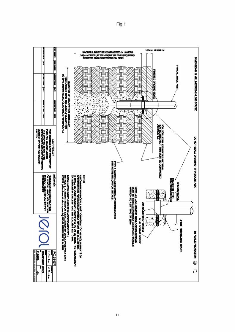
(4) METHOD STATEMENT FOR INSTALLATION OF JEROL PASSIVELY SAFESIGN POSTS (without electrical components)
See figure 1.
4.1 Assembly and installation of posts
• Insert the pole caps if provided, knocking in with a rubber mallet.• Place the pressure distribution ring over the post and draw it down to approximately
1.0 m above ground level.
• Place the protection cover over the post and draw it down to just above the pressuredistribution ring
• Use a rope or sling to make a snare and place it just above the protection cover.
Then make another snare of the same rope at the top of the post. Connect the end of
the rope to the crane and lift the post, lowering it into the foundation.• When the post is in position in the foundation, with a rubber mallet position the
distribution ring to line up with the adjustment screws.
• Remove the securing bolt plastic covers by inserting a medium sized screw driver intothe cover and unscrewing
• Straighten and adjust the post(s) using an 8mm hexagonal wrench to tighten the
adjustment screws onto the pressure distribution ring to 60 Nm using a calibratedtorque wrench.
• Apply threadlock (Loctite 243) to the locking bolts supplied and insert and
tighten onto the fixing bolts. Tighten to 60Nm.
• Place the rubber protection cover over the foundation.• Replace the plastic covers to the securing bolts and complete the backfill.
• Backfill to ground level which should be a minimum 100mm above the top of the
foundation.
9
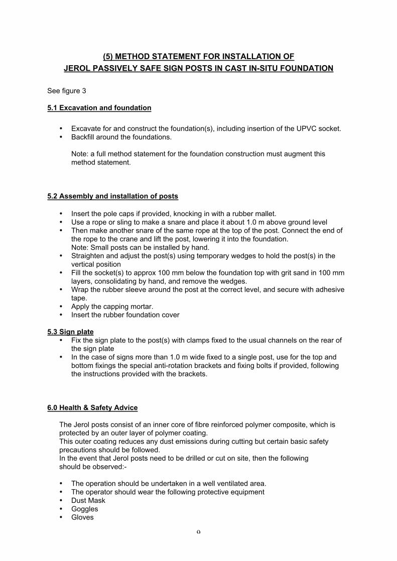
(5) METHOD STATEMENT FOR INSTALLATION OF
JEROL PASSIVELY SAFE SIGN POSTS IN CAST IN-SITU FOUNDATION
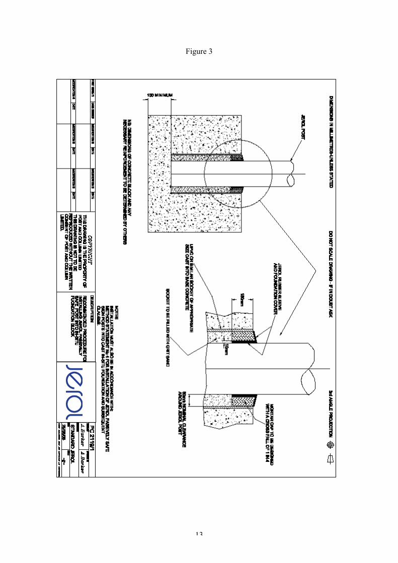
See figure 3
5.1 Excavation and foundation
• Excavate for and construct the foundation(s), including insertion of the UPVC socket.
• Backfill around the foundations.
Note: a full method statement for the foundation construction must augment this
method statement.
5.2 Assembly and installation of posts
• Insert the pole caps if provided, knocking in with a rubber mallet.
• Use a rope or sling to make a snare and place it about 1.0 m above ground level• Then make another snare of the same rope at the top of the post. Connect the end of
the rope to the crane and lift the post, lowering it into the foundation.
Note: Small posts can be installed by hand.• Straighten and adjust the post(s) using temporary wedges to hold the post(s) in the
vertical position
• Fill the socket(s) to approx 100 mm below the foundation top with grit sand in 100 mm
layers, consolidating by hand, and remove the wedges.• Wrap the rubber sleeve around the post at the correct level, and secure with adhesive
tape.
• Apply the capping mortar.• Insert the rubber foundation cover
5.3 Sign plate
• Fix the sign plate to the post(s) with clamps fixed to the usual channels on the rear ofthe sign plate
• In the case of signs more than 1.0 m wide fixed to a single post, use for the top and
bottom fixings the special anti-rotation brackets and fixing bolts if provided, followingthe instructions provided with the brackets.
6.0 Health & Safety Advice
The Jerol posts consist of an inner core of fibre reinforced polymer composite, which isprotected by an outer layer of polymer coating.
This outer coating reduces any dust emissions during cutting but certain basic safety
precautions should be followed.In the event that Jerol posts need to be drilled or cut on site, then the following
should be observed:-
• The operation should be undertaken in a well ventilated area.
• The operator should wear the following protective equipment
• Dust Mask
• Goggles• Gloves
10
7.0 Treatment after cutting
After cutting the cut end of the post should be re-sealed to prevent moisture entering the
fibre composite.core. The sealing can be achieved by applying a coating of clear exterior
varnish.
11
Fig 1
12
Fig 2
13
Figure 3
14
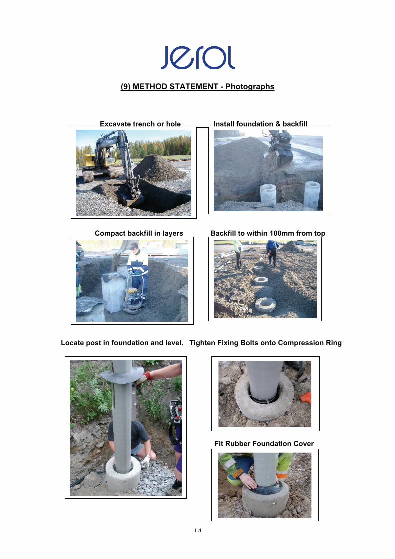
(9) METHOD STATEMENT - Photographs
Excavate trench or hole Install foundation & backfill
Compact backfill in layers Backfill to within 100mm from top
Locate post in foundation and level. Tighten Fixing Bolts onto Compression Ring
Fit Rubber Foundation Cover