Embed Size (px)
Citation preview
OO方法、 RUP与 UML建模
首席软件专家 张恂博讯科技(上海)有限公司
浩方科技集团2000.11
主要内容
一、 OOAD与 UML表示法
二、 RUP建模过程与步骤
三、讨论
一、 OOAD与 UML表示法
OO原则
• Abstraction(抽象)• Encapsulation(封装)• Modularity(模块化)• Hierarchy(分层)
OO三要素• 封装
• 继承
• 多态
OO基本概念• 对象• 类• 属性• 操作(方法)• 接口(多态)
*
• 构件 *
• 关系• 包• 子系统 *
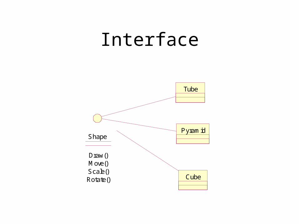
接口与多态• Polymorphism: The ability to hide many
different implementations behind a single interface.
• Interfaces formalize polymorphism, support “plug-and-play” architectures.
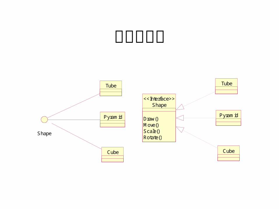
接口与多态
Shape
Tube
Pyramid
Cube
Shape
Draw()Move()Scale()Rotate()
<<Interface>>
Tube
Pyramid
Cube
Component
• A non-trivial, nearly independent, and replaceable part of a system that fulfills a clear function in the context of a well-defined architecture.
• source code component, run time components, executable component
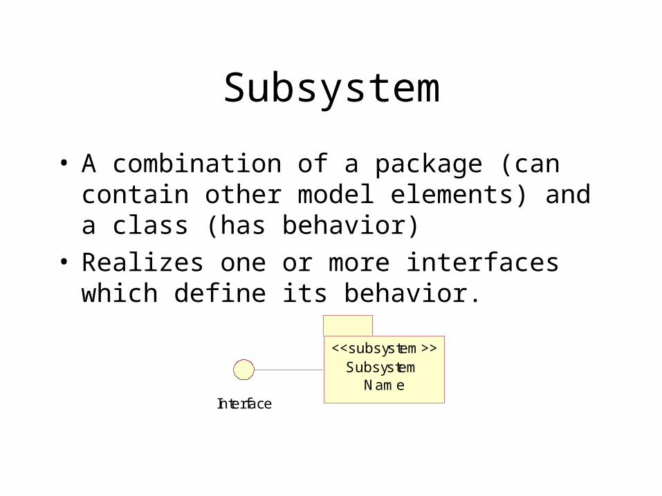
Subsystem
• A combination of a package (can contain other model elements) and a class (has behavior)
• Realizes one or more interfaces which define its behavior.
Subsystem Name
<<subsystem>>
Interface
OOAD是主流技术OOAD大部分情况下比结构化设计好:结构化设计是过时的东西,它强调软件的结构按照功能来组织,一旦功能改变,软件的结构就会不稳定。而 OO设计把数据流和功能统一起来, IT行业绝大部分( 70-80%)的软件设计(包括数据库设计)可以采用 OO方法,目前国外流行的趋势也是这样,剩下的少部分有特定需求的可能还会用传统方法。另外在电信界,用有限自动状态机的 SDL方法仍占绝大数,但现在 UML和 SDL出现了融合的趋势。
Object Oriented Analysis
• 用面向对象方法分析问题域,建立基于对象、消息的业务模型,形成对客观世界和业务本身的正确认识。
• 生成业务对象的动、静态模型和抽象类。
Object Oriented Design
• 针对 OOA给出的问题域模型,用面向对象方法设计出软件基础架构(概要设计)和完整的类结构(详细设计),以实现业务功能。
• 生成对象类的动、静态模型(解决域)。
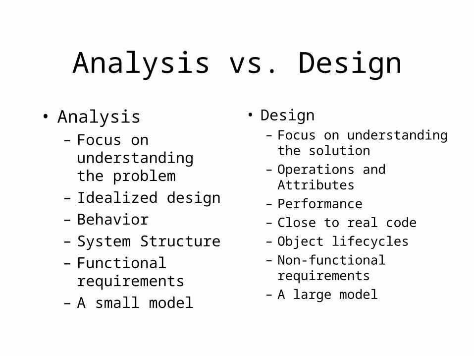
Analysis vs. Design
• Analysis– Focus on
understanding the problem
– Idealized design
– Behavior
– System Structure
– Functional requirements
– A small model
• Design– Focus on understanding
the solution– Operations and Attributes– Performance– Close to real code– Object lifecycles– Non-functional
requirements– A large model
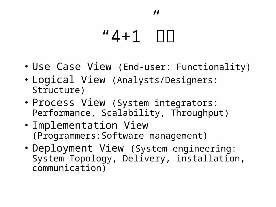
“4+1”视图• Use Case View (End-user: Functionality)
• Logical View (Analysts/Designers: Structure)
• Process View (System integrators: Performance, Scalability, Throughput)
• Implementation View (Programmers:Software management)
• Deployment View (System engineering: System Topology, Delivery, installation, communication)
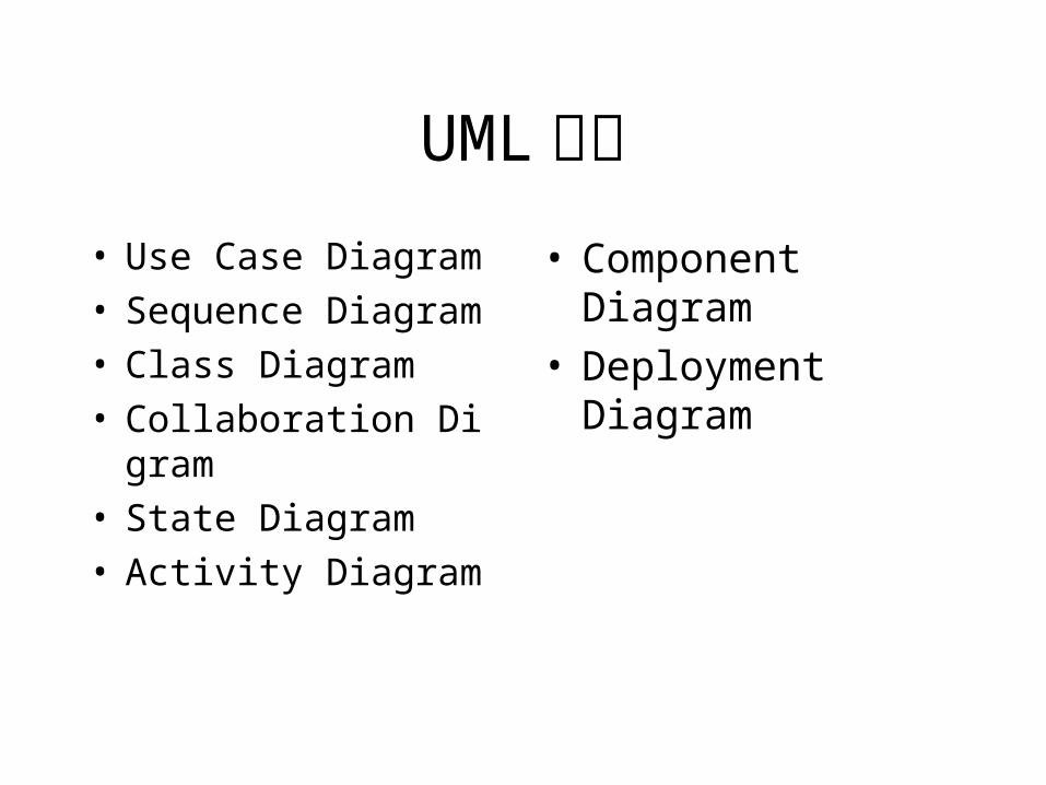
UML图示• Use Case Diagram• Sequence Diagram• Class Diagram• Collaboration Digram• State Diagram• Activity Diagram
• Component Diagram• Deployment Diagram
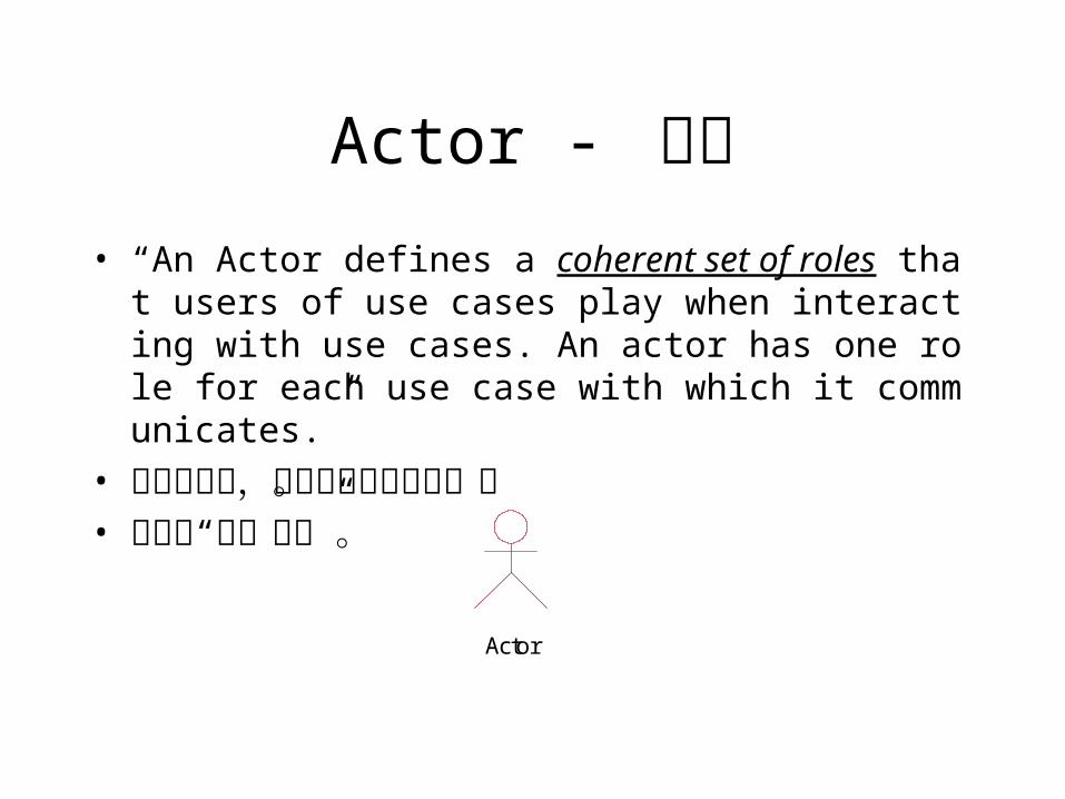
Actor - 用户• “An Actor defines a coherent set of roles that users of use
cases play when interacting with use cases. An actor has one role for each use case with which it communicates.”
• 角色的集合,可以是人或外部系统。• 定义了“系统边界”。
Actor
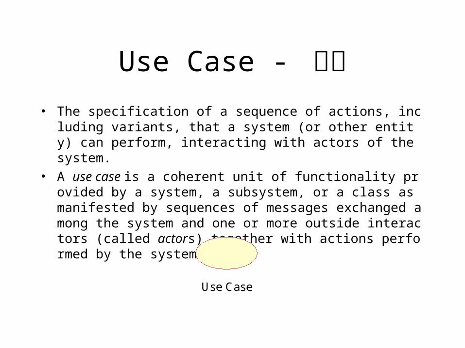
Use Case - 用例• The specification of a sequence of actions, including variants, that a sy
stem (or other entity) can perform, interacting with actors of the system.
• A use case is a coherent unit of functionality provided by a system, a subsystem, or a class as manifested by sequences of messages exchanged among the system and one or more outside interactors (called actors) together with actions performed by the system.
Use Case
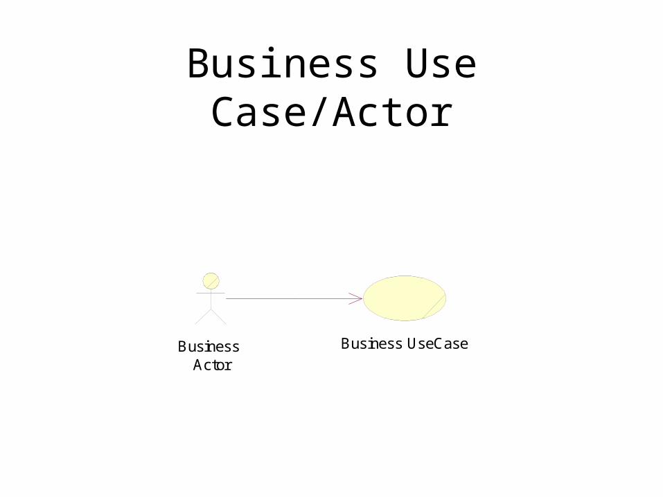
Business Use Case/Actor
Business Actor
Business UseCase
Business - System
• 例子
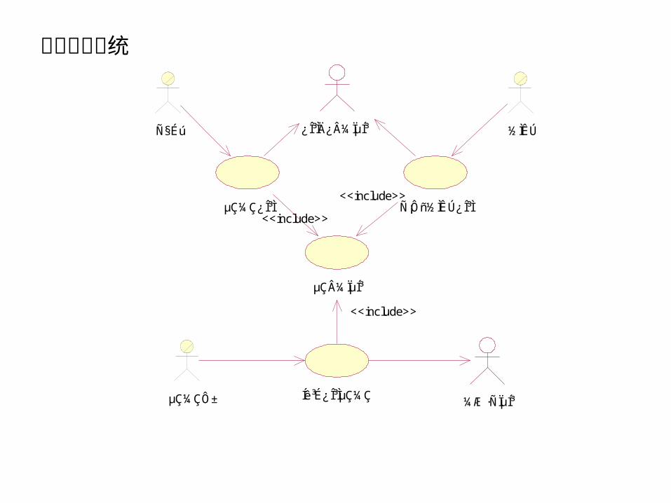
µÇ¼ϵͳ
µÇ¼ÇÔ± Íê³É¿Î³ÌµÇ¼Ç ¼Æ·Ñϵͳ
ѧÉú
µÇ¼Ç¿Î³Ì
½ÌÊÚ
Ñ¡Ôñ½ÌÊڿγÌ
¿Î³ÌĿ¼ϵͳ
<<include>>
<<include>>
<<include>>
课程登记系统
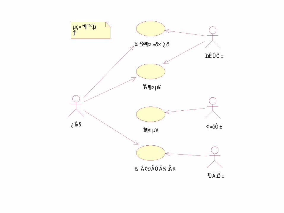
϶©µ¥
ÏúÊÛÔ±
¼ì²é¶©»õ×´¿ö
¹ÜÀíÔ±
·¢»õÔ±Ìµ¥
¿Í»§
½¨Á¢ÐÅÓüͼ
µç»°¶¨¹ºÏµÍ³
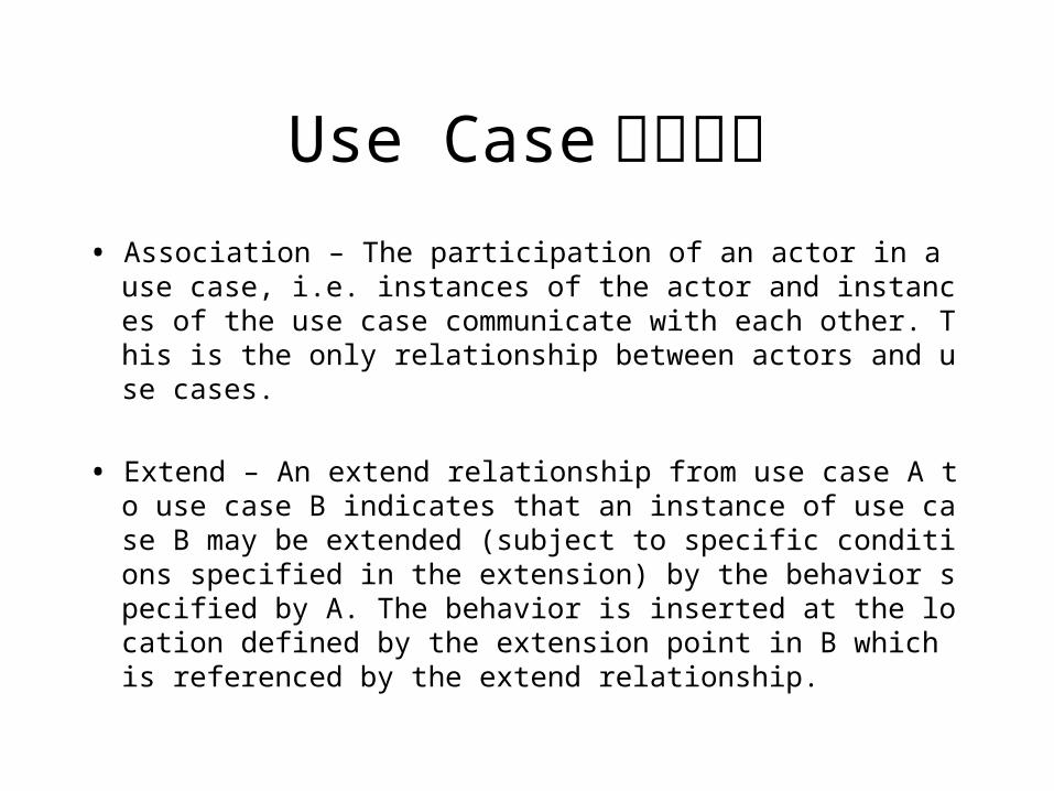
Use Case依赖关系• Association – The participation of an actor in a use case, i.e.
instances of the actor and instances of the use case communicate with each other. This is the only relationship between actors and use cases.
• Extend – An extend relationship from use case A to use case B indicates that an instance of use case B may be extended (subject to specific conditions specified in the extension) by the behavior specified by A. The behavior is inserted at the location defined by the extension point in B which is referenced by the extend relationship.
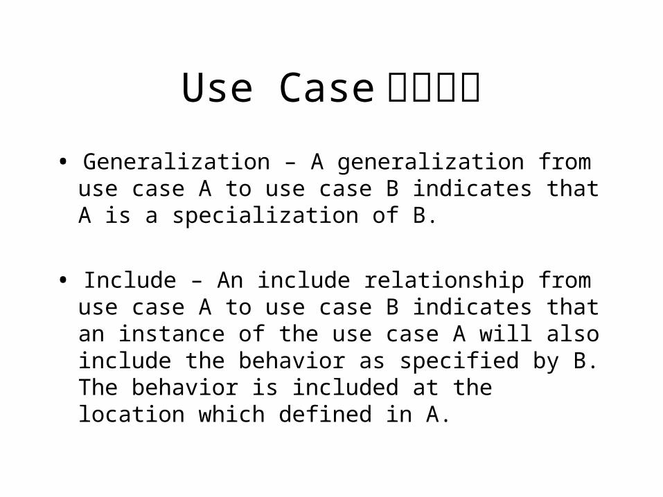
Use Case依赖关系• Generalization – A generalization from use case A
to use case B indicates that A is a specialization of B.
• Include – An include relationship from use case A to use case B indicates that an instance of the use case A will also include the behavior as specified by B. The behavior is included at the location which defined in A.
ÏúÊÛÔ± ϶©µ¥
Ìṩ¿Í»§Êý¾Ý ¶¨¹º²úÆ· °²ÅŸ¶¿î
µ÷ÔIJúƷĿ¼
<<include>>
<<include>>
<<include>>
<<extend>>
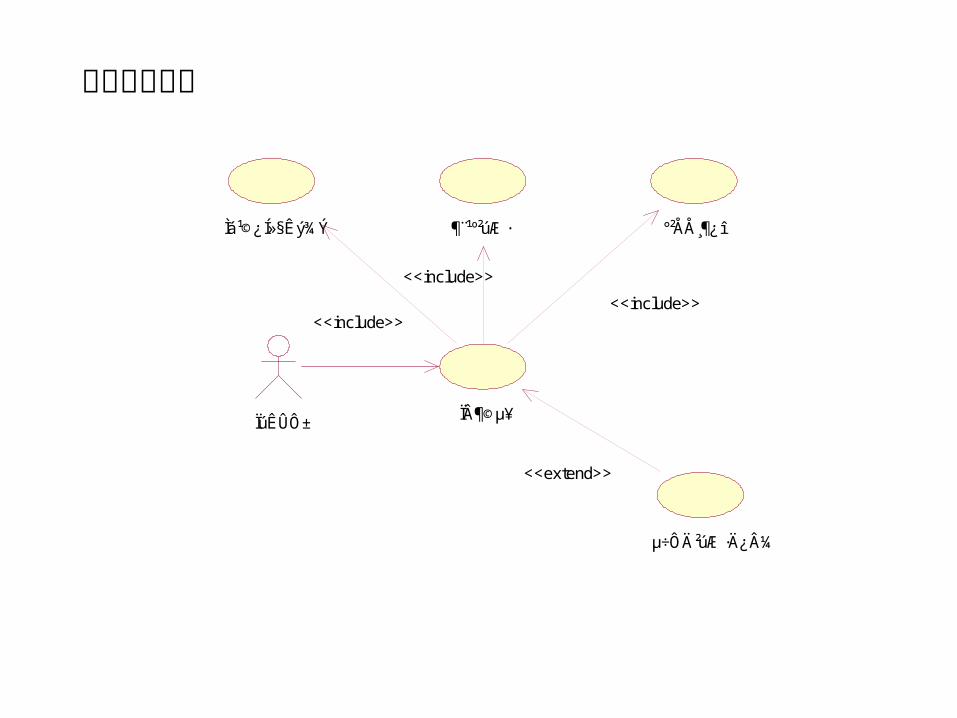
产品定购管理
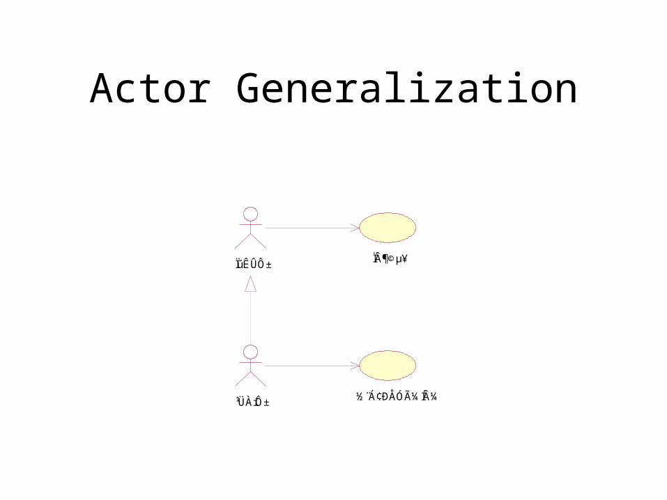
Actor Generalization
϶©µ¥ÏúÊÛÔ±
¹ÜÀíÔ± ½¨Á¢ÐÅÓüͼ
Sequence Diagram
A diagram that shows object interactions arranged in time sequence. In particular, it shows the objects participating in the interaction and the sequence of messages exchanged.
Unlike a collaboration diagram, a sequence diagram includes time sequences but does not include object relationships.
A sequence diagram can exist in a generic form (describes all possible scenarios) and in an instance form (describes one actual scenario).
Sequence diagrams and collaboration diagrams express similar information, but show it in different ways.
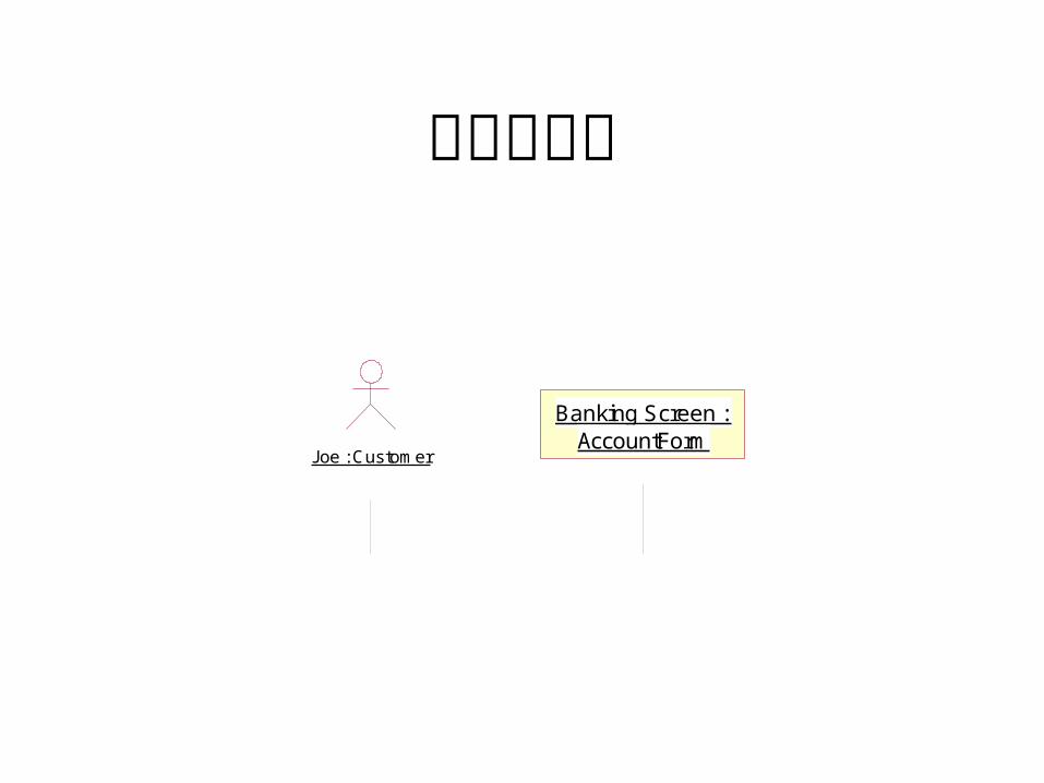
序列图元素
Joe : Customer
Banking Screen : AccountForm
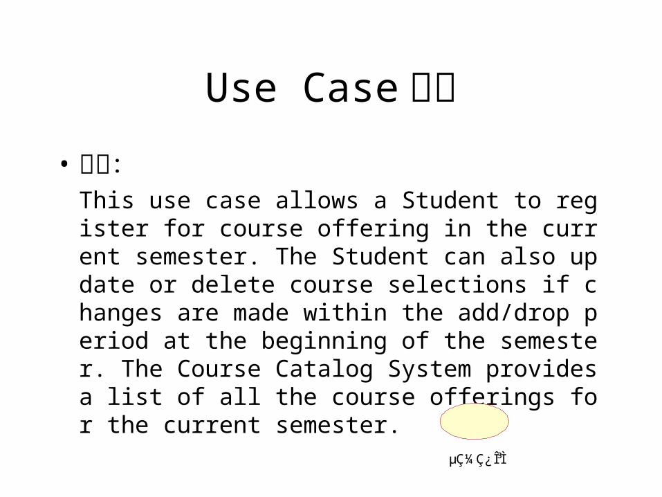
Use Case描述• 简述:
This use case allows a Student to register for course offering in the current semester. The Student can also update or delete course selections if changes are made within the add/drop period at the beginning of the semester. The Course Catalog System provides a list of all the course offerings for the current semester.
µÇ¼Ç¿Î³Ì
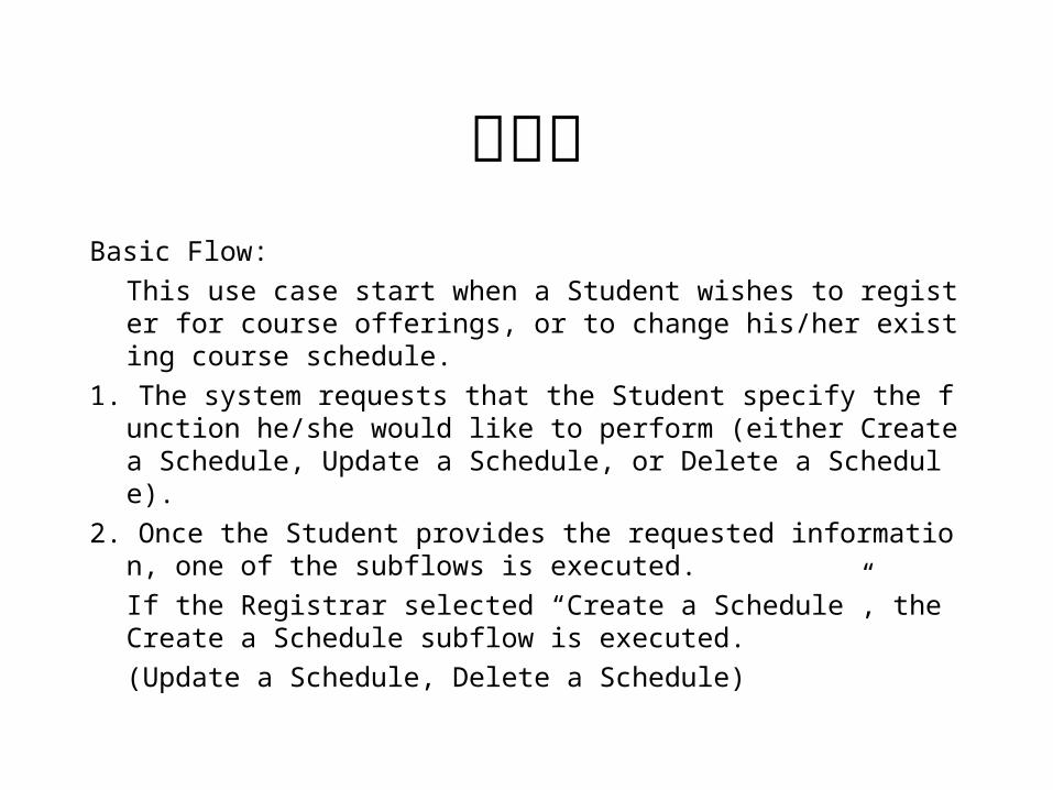
事件流Basic Flow:
This use case start when a Student wishes to register for course offerings, or to change his/her existing course schedule.
1. The system requests that the Student specify the function he/she would like to perform (either Create a Schedule, Update a Schedule, or Delete a Schedule).
2. Once the Student provides the requested information, one of the subflows is executed.
If the Registrar selected “Create a Schedule”, the Create a Schedule subflow is executed.
(Update a Schedule, Delete a Schedule)
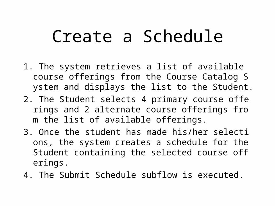
Create a Schedule
1. The system retrieves a list of available course offerings from the Course Catalog System and displays the list to the Student.
2. The Student selects 4 primary course offerings and 2 alternate course offerings from the list of available offerings.
3. Once the student has made his/her selections, the system creates a schedule for the Student containing the selected course offerings.
4. The Submit Schedule subflow is executed.
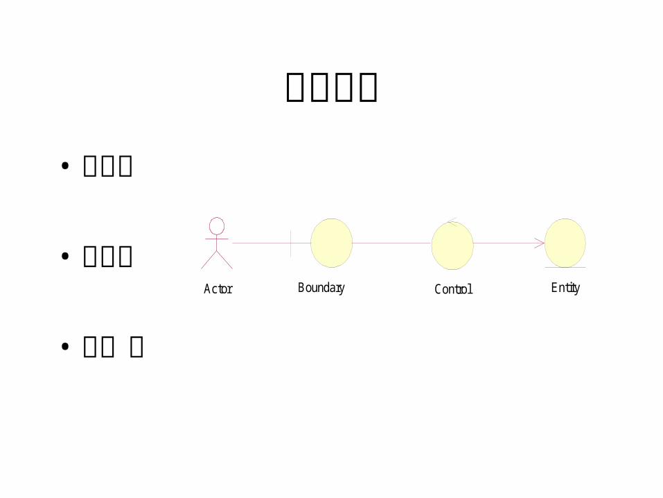
类的划分• 边界类
• 控制类
• 实体类
Control EntityActor Boundary
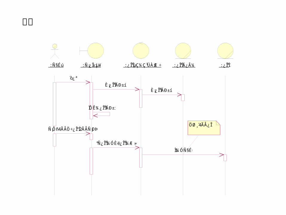
: ѧÉú : Ñ¡¿Î±íµ¥ : ¿Î³ÌµÇ¼Ç¹ÜÀíÆ÷ : ¿Î³ÌĿ¼ : ¿Î³Ì
´ò¿ª
È¡¿Î³ÌÁбíÈ¡¿Î³ÌÁбí
ÏÔʾ¿Î³ÌÁбí
Ñ¡Ôñ4ÃÅÖ÷¿ÎºÍ2ÃÅÑ¡ÐÞ¿Î
°Ñ¿Î³Ì¼ÓÈë¿Î³Ì¼Æ»®
Ìí¼ÓѧÉú
Öظ´4ÃÅ¿Î
选课
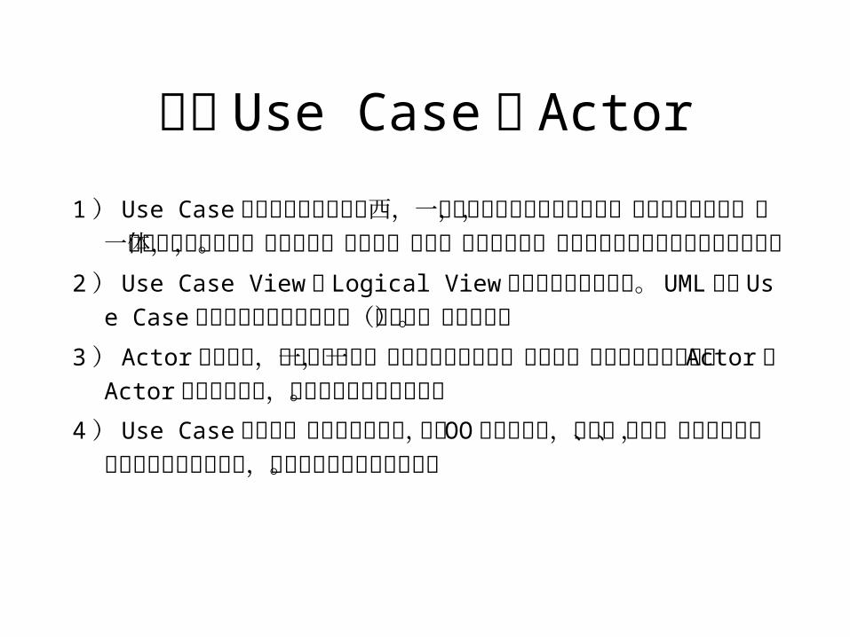
理解 Use Case和 Actor
1) Use Case绝不是锦上添花的东西,一方面它可以促进与用户沟通,理解正确的需求,另一方面它可以划分系统与外部实体的界限,是系统设计的起点,而最终应该落实到类和实现代码上。
2) Use Case View与 Logical View应该由明确的相关性。 UML中从Use Case到类包的关联可以用依赖(或实现)关系描述。
3) Actor不是指人,而是指代表某一种特定功能的角色,因此同一个人可能对应很多个 Actor。 Actor是虚拟的概念,可以指外部系统和设备。
4) Use Case是对系统行为的动态描述,它是 OO设计的起点,是类、对象、操作的来源,而通过逻辑视图的设计,可以获得软件的静态结构。
Class Diagram
A diagram that shows a collection of declarative (static)
model elements, such as classes, types, and their contents
and relationships.
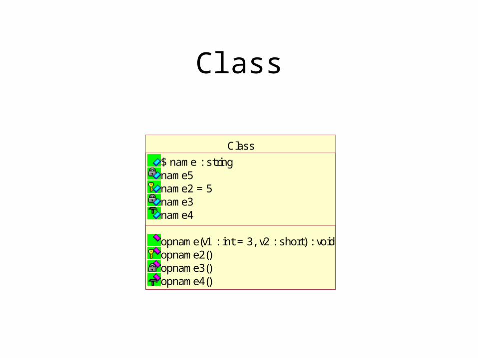
Class
Class
$ name : stringname5name2 = 5name3name4
opname(v1 : int = 3, v2 : short) : voidopname2()opname3()opname4()
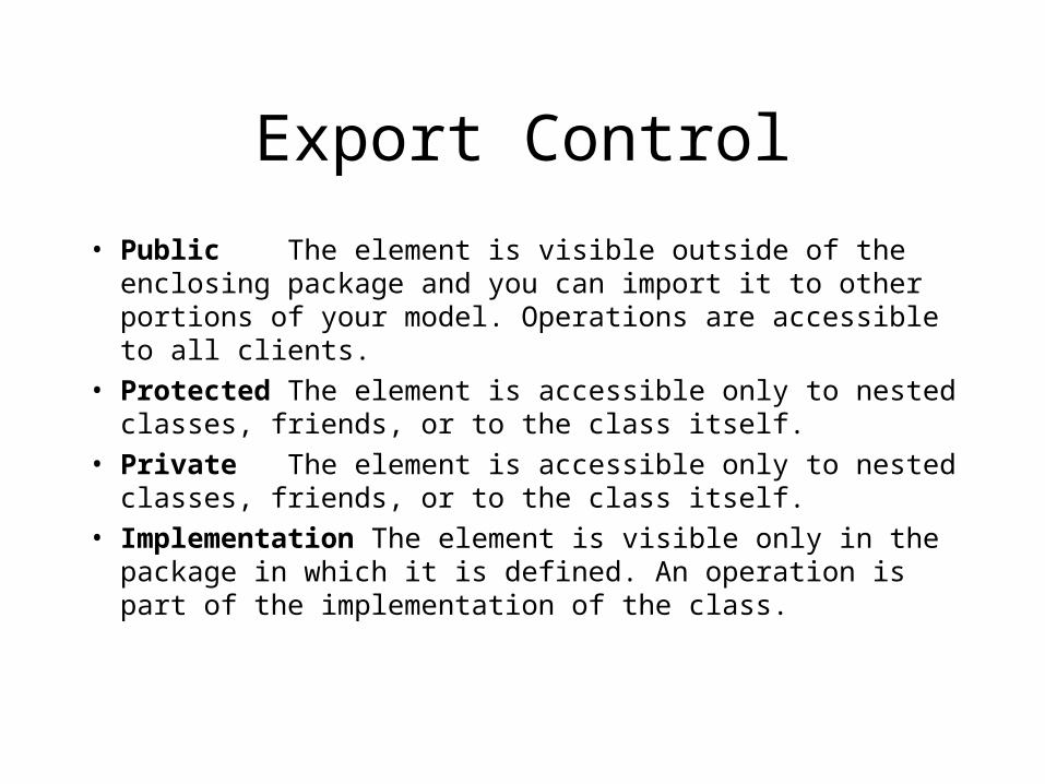
Export Control
• Public The element is visible outside of the enclosing package and you can import it to other portions of your model. Operations are accessible to all clients.
• Protected The element is accessible only to nested classes, friends, or to the class itself.
• Private The element is accessible only to nested classes, friends, or to the class itself.
• Implementation The element is visible only in the package in which it is defined. An operation is part of the implementation of the class.
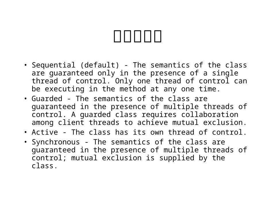
类的并发性• Sequential (default) - The semantics of the class are
guaranteed only in the presence of a single thread of control. Only one thread of control can be executing in the method at any one time.
• Guarded - The semantics of the class are guaranteed in the presence of multiple threads of control. A guarded class requires collaboration among client threads to achieve mutual exclusion.
• Active - The class has its own thread of control.• Synchronous - The semantics of the class are guaranteed in
the presence of multiple threads of control; mutual exclusion is supplied by the class.
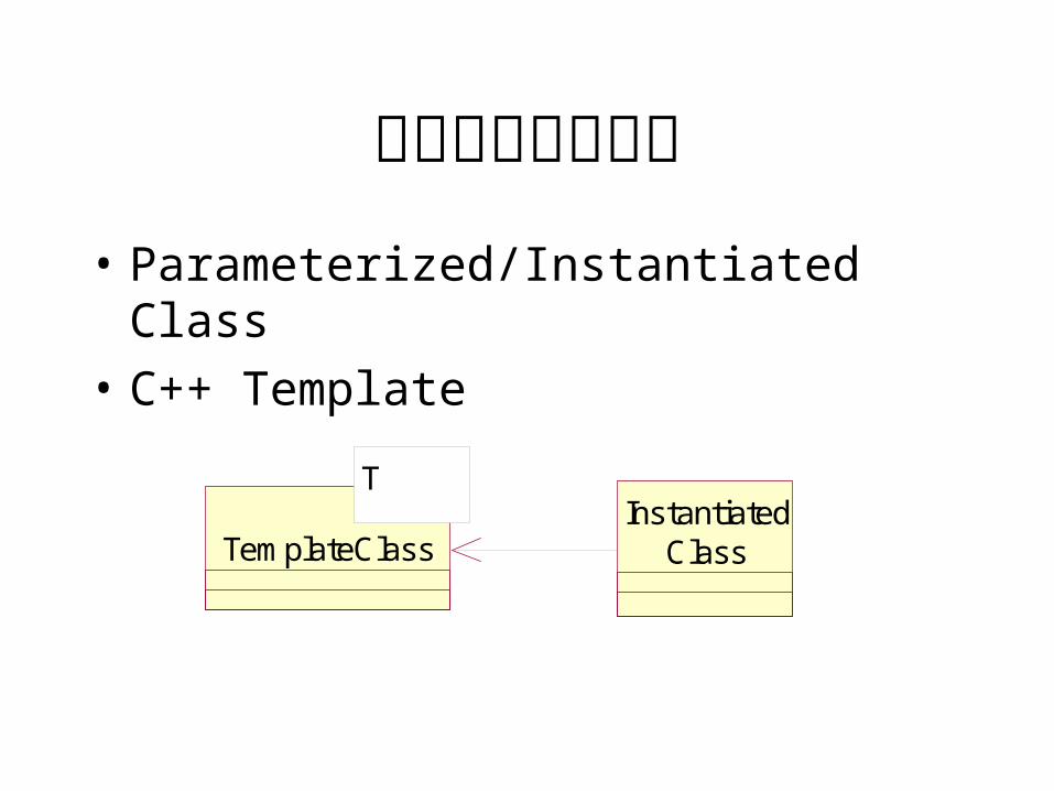
参数化和实例化类• Parameterized/Instantiated Class
• C++ Template
T
TemplateClassInstantiated
Class
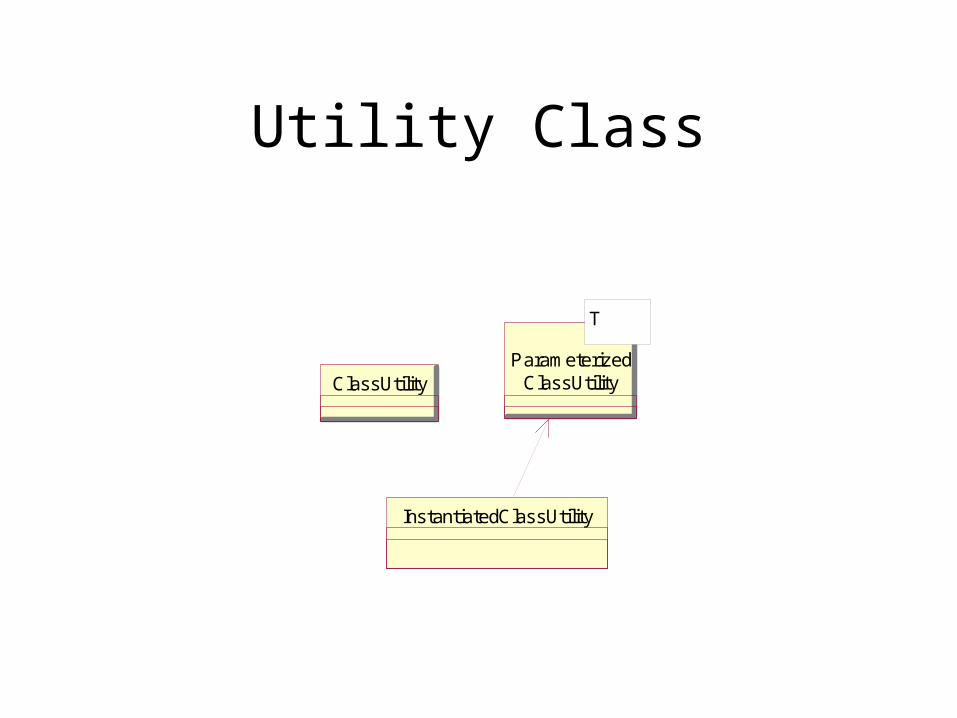
Utility Class
ClassUtility
InstantiatedClassUtility
T
ParameterizedClassUtility
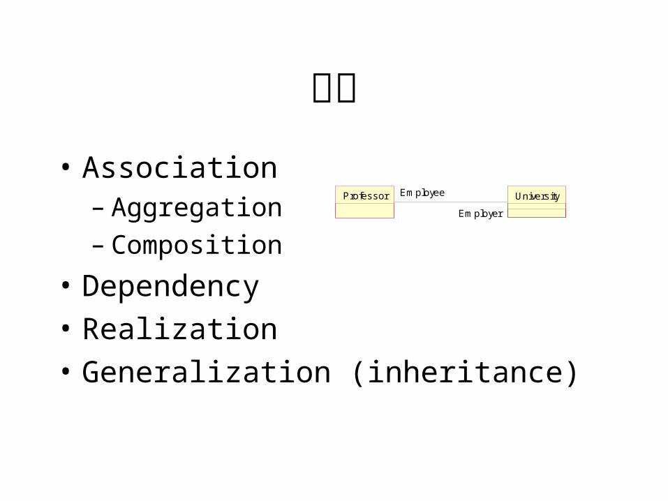
关系• Association
– Aggregation– Composition
• Dependency
• Realization
• Generalization (inheritance)
Professor UniversityEmployee
Employer
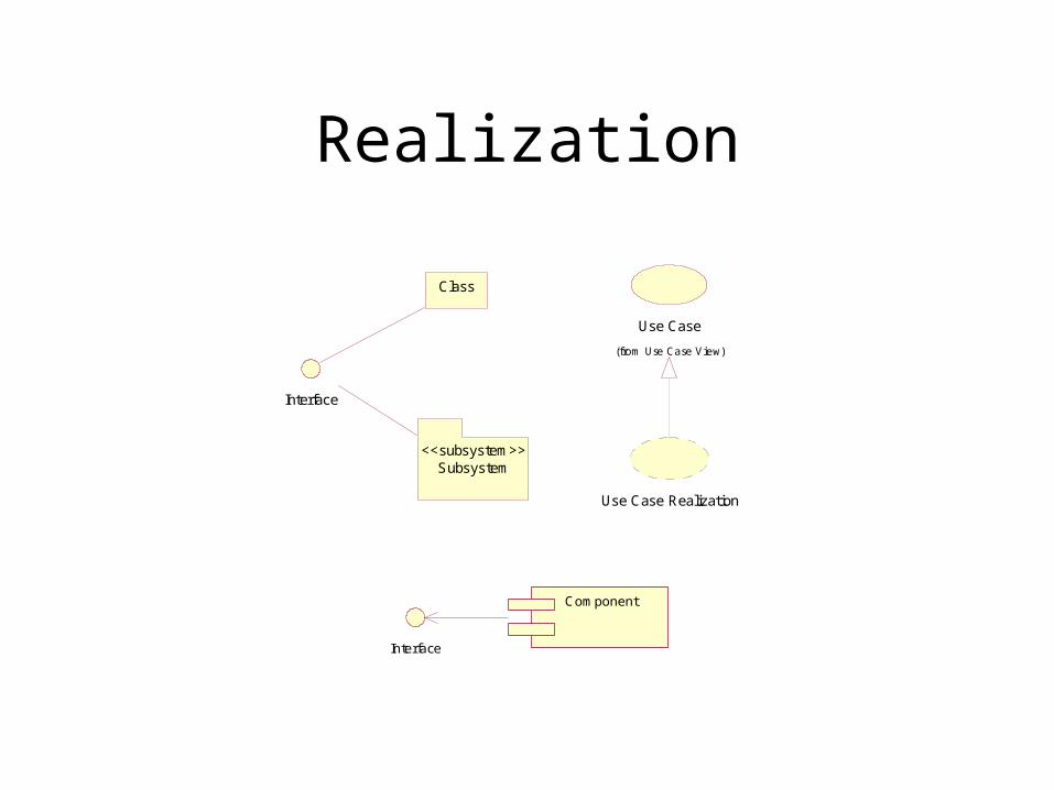
Realization
Class
Interface
Subsystem<<subsystem>>
Use Case
(from Use Case View)
Use Case Realization
Component
Interface
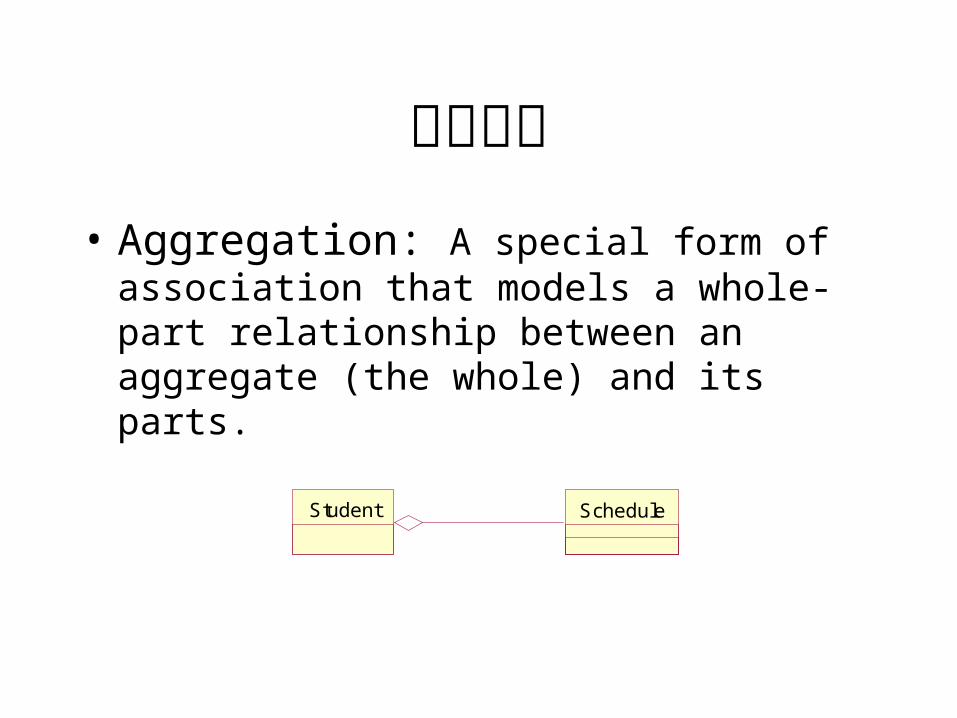
聚合关系• Aggregation: A special form of association that
models a whole-part relationship between an aggregate (the whole) and its parts.
Student Schedule
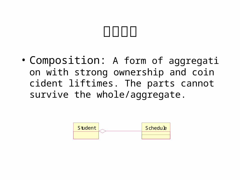
合成关系• Composition: A form of aggregation with strong
ownership and coincident liftimes. The parts cannot survive the whole/aggregate.
Student Schedule
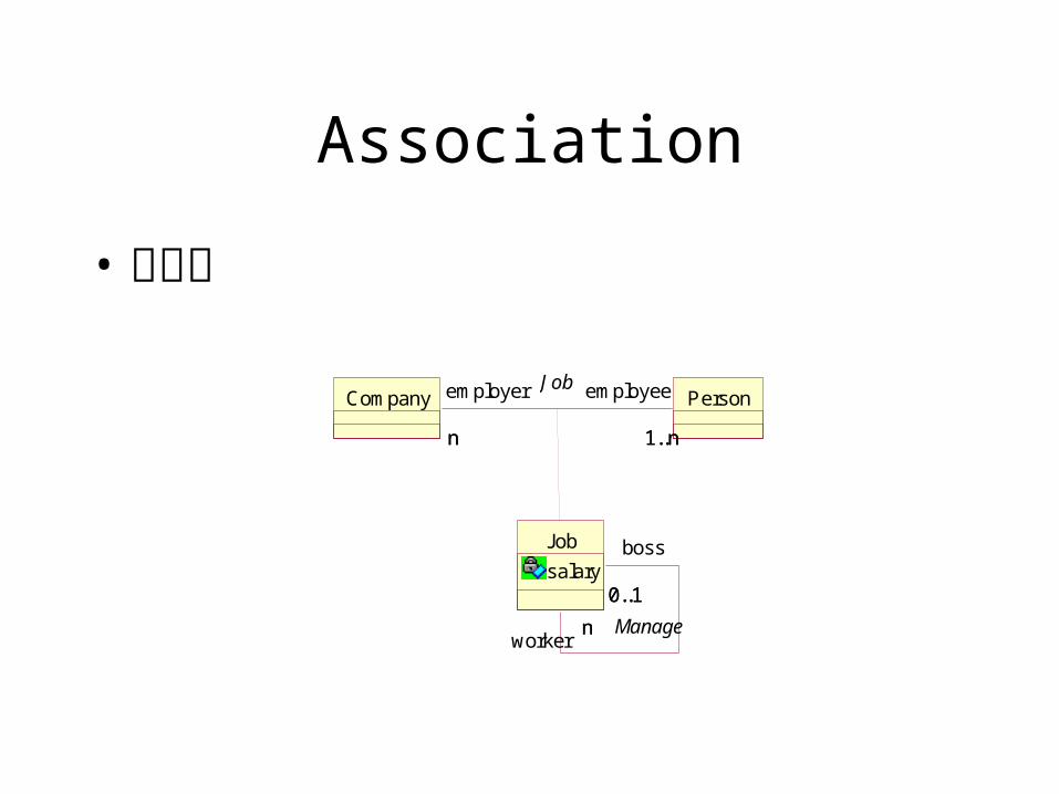
Association
• 关联类
Company Person
1..nn 1..nn
employeeemployer
Job
salary0..1
n
boss
worker
Job
Manage
0..1
n
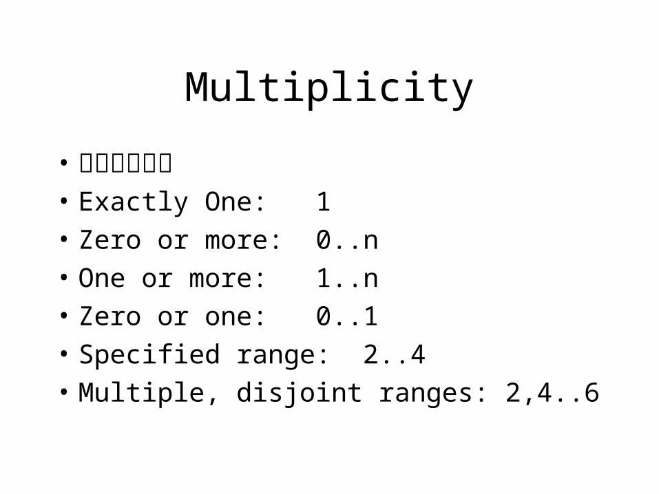
Multiplicity
• 关系的多重性• Exactly One: 1
• Zero or more: 0..n
• One or more: 1..n
• Zero or one: 0..1
• Specified range: 2..4
• Multiple, disjoint ranges: 2,4..6
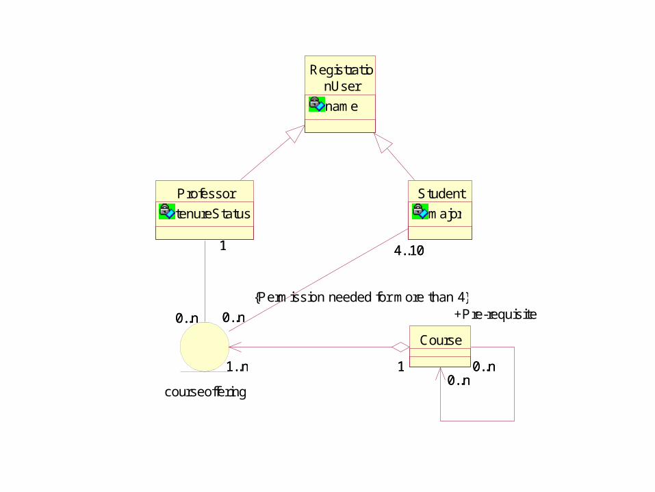
RegistrationUser
name
Course
0..n0..n
Professor
tenureStatus
Student
major
courseoffering
1..n 1
0..n
1
0..n
4..10
0..n0..n
1
0..n0..n
1..n
+Pre-requisite
4..10
1
{Permission needed for more than 4}
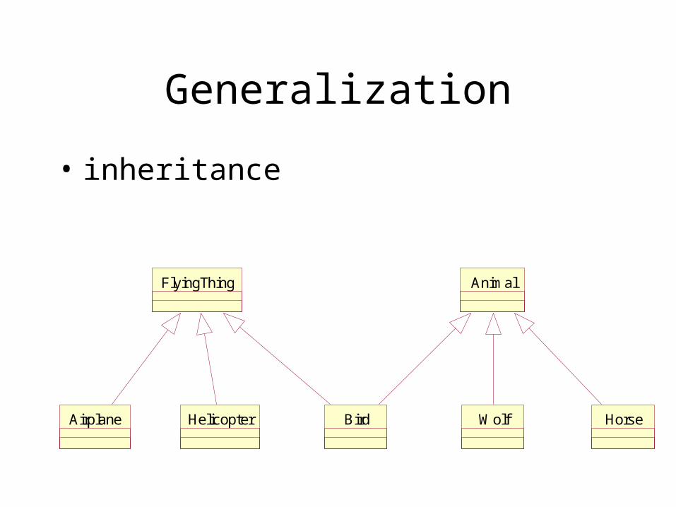
Generalization
• inheritance
FlyingThing Animal
Airplane Helicopter Bird Wolf Horse
Dependency
• A dependency indicates a semantic relationship between two (or more) model elements. It relates the model elements themselves and does not require a set of instances for its meaning. It indicates a situation in which a change to the target element may require a change to the source
element in the dependency.
依赖关系• bind – Binding: A binding of template parameters to actual
values to create a nonparameterized element.
• trace – Trace: A historical connection between two elements that represent the same concept at different levels of meaning.
• refine – Refinement: A historical or derivation connection between two elements with a mapping (not necessarily complete) between them.
依赖关系• use – Usage: A situation in which one element requires the
presence of another element for its correct implementation or functioning. May be stereotyped further to indicate the exact nature of the dependency, such as calling an operation of another class, granting permission for access,
instantiating an object of another class, etc. Maps into a Usage.
If the keyword is one of the stereotypes of Usage (call, create, instantiate, send) then it maps into a Usage with the given stereotype.
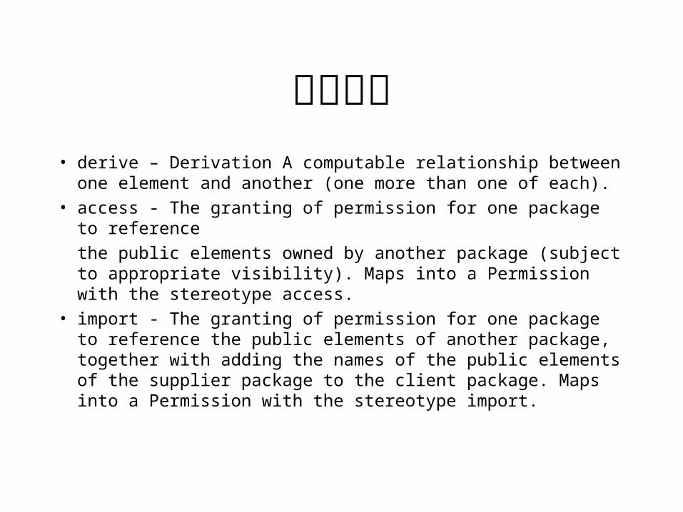
依赖关系• derive – Derivation A computable relationship between one
element and another (one more than one of each).• access - The granting of permission for one package to reference
the public elements owned by another package (subject to appropriate visibility). Maps into a Permission with the stereotype access.
• import - The granting of permission for one package to reference the public elements of another package, together with adding the names of the public elements of the supplier package to the client package. Maps into a Permission with the stereotype import.
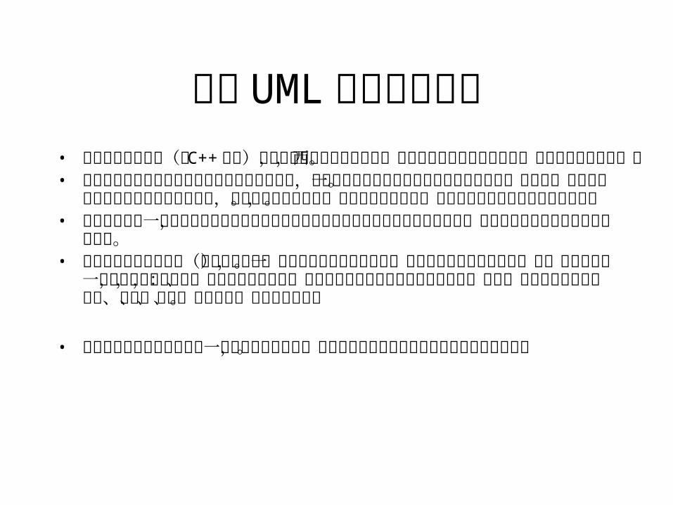
四种 UML依赖关系异同• 绑定关系位于模板(如 C++模板)和用其生成的模型元素之间,该元素完全是模板的实例化,为添加任何新的东西。
• 可溯关系是两个元素或元素集合之间的概念连接,用于描述位于不同语义层或多种视点下的同一个概念。这些元素间并没有任何特定的映射关系,关系的方向可被忽略。通常用于跟踪需求,或帮助建模者跟踪多个模型的变化。
• 使用关系表示一个元素为了实现或完成其全部的功能需要其它元素或元素集合的配合,例如类与类之间的多种方法调用关系。
• 细化关系是不同语义层(如分析和设计)之间模型元素的依赖关系,表示客户可由供应者导出。这一导出关系不一定非要用算法来描述,可以完全人为决定,因此细化关系可描述的语义范围较广,包括:模型的逐步细化、优化、变换、模板、模型合成、框架组成等等。
• 绑定和使用关系只能用于同一模型中元素的连接,而可溯和细化关系可用于连接多个模型的元素。
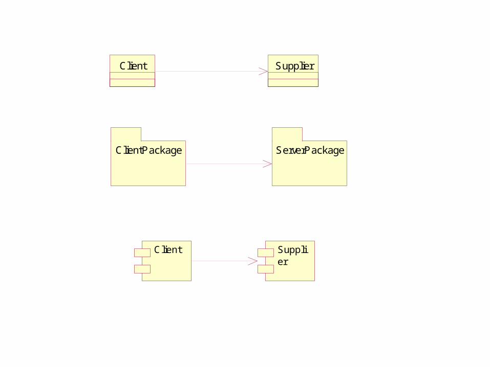
Client Supplier
ClientPackage ServerPackage
Client Supplier
Interface
Shape
Draw()Move()Scale()Rotate()
Tube
Pyramid
Cube
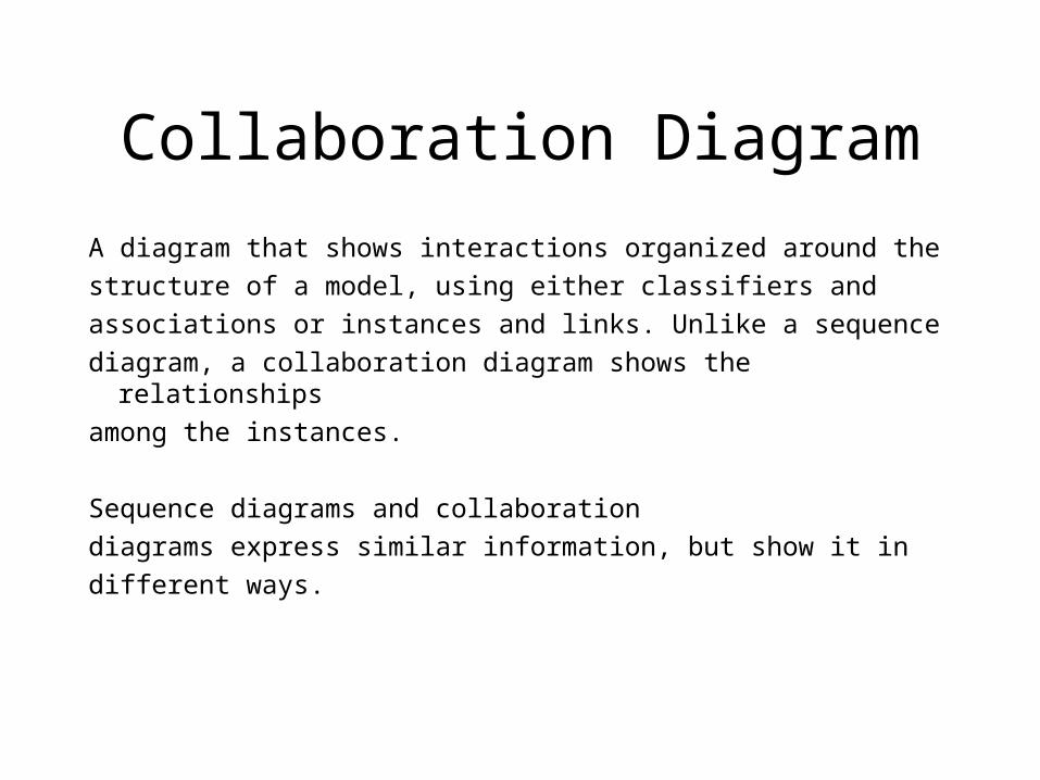
Collaboration Diagram
A diagram that shows interactions organized around the
structure of a model, using either classifiers and
associations or instances and links. Unlike a sequence
diagram, a collaboration diagram shows the relationships
among the instances.
Sequence diagrams and collaboration
diagrams express similar information, but show it in
different ways.
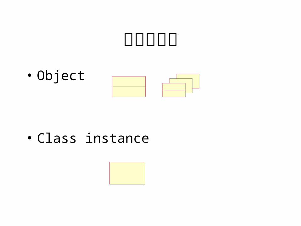
协作图元素• Object
• Class instance
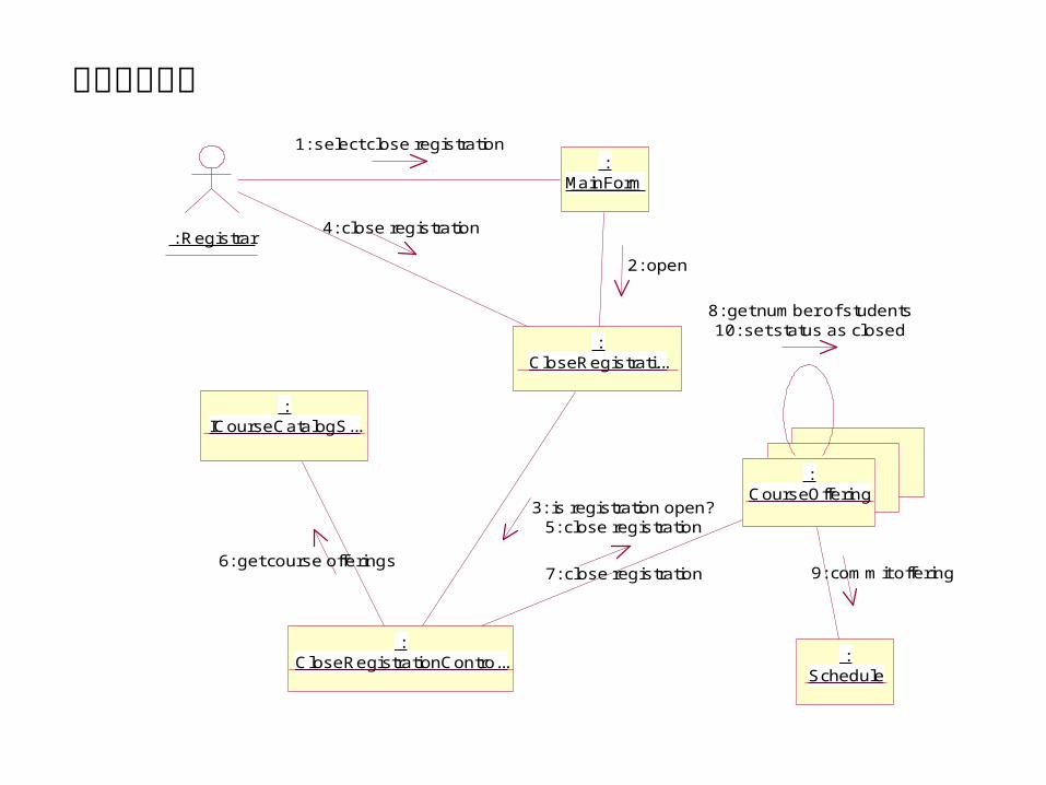
: Registrar
: CloseRegistrati...
: MainForm
: ICourseCatalogS...
: CloseRegistrationContro...
: CourseOffering
: Schedule
8: get number of students10: set status as closed
1: select close registration
4: close registration
3: is registration open?5: close registration
2: open
7: close registration6: get course offerings
9: commit offering
完成课程登记
State Diagram
State:
A condition or situation during the life of an object during which it satisfies some condition, performs some activity, or waits for some event.
³õʼ»¯
entry/ ´´½¨±íµ¥do/ ³õʼ»¯±íµ¥
±£´æ
do/ ±£´æ±íµ¥
Ìá½»
do/ Ìá½»±íµ¥ÓÃÓÚ ¦́Àí
¿Î³ÌÑ¡Ôñ
Ñ¡Ö÷ÐÞ¿Î
entry/ ½ÓÊܿγÌdo/ Ôö¼Ó¼ÇÊý
Ñ¡̧ ¨ÐÞ¿Î
entry/ ½ÓÊܿγÌexit/ Ôö¼Ó¼ÇÊý
H
Ñ¡Ö÷ÐÞ¿Î
entry/ ½ÓÊܿγÌdo/ Ôö¼Ó¼ÇÊý
Ñ¡̧ ¨ÐÞ¿Î
entry/ ½ÓÊܿγÌexit/ Ôö¼Ó¼ÇÊý
¹ÒÆð
do/ µÈ´ý30Ãë
ÊäÈë¿Î³Ì [ count=2 ]
[ count=4 ] / set count=0
Quit
ÊäÈë¿Î³Ì
ÊäÈë¿Î³Ì
¹ÒÆð
H
»Ö¸´
选课
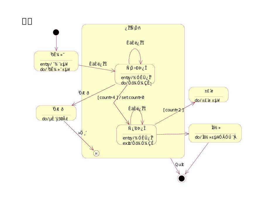
History
• The history icon provides a mechanism to return to the most recently visited state or activity when transitioning directly to a state or activity with substates. History applies to the given level in which it appears.
³õʼ»¯
³·Ïú
Íê³ÉµÇ¼Ç
µÇ¼Ç
´ò¿ª
entry/ µÇ¼ÇѧÉúexit/ Ôö¼ÓѧÉú¼ÇÊý
¹Ø±Õ
do/ Í̈ ÖªÆäËüѧÉú¸Ã¿Î³ÌµÇ¼ÇÒÑÂú
δ·ÖÅä
´ò¿ª
entry/ µÇ¼ÇѧÉúexit/ Ôö¼ÓѧÉú¼ÇÊý
¹Ø±Õ
do/ Í̈ ÖªÆäËüѧÉú¸Ã¿Î³ÌµÇ¼ÇÒÑÂú
δ·ÖÅä
Ìí¼ÓѧÉú( ѧÉú )
È¡Ïû¿Î³Ì
½áÊøµÇ¼Ç[ ѧÉúÊý<3 ]
½áÊøµÇ¼Ç[ ѧÉúÊý>=3 ] [ ѧÉúÊý=10 ] ^»¨Ãû²á.´´½¨»¨Ãû²á
Ìí¼ÓѧÉú( ѧÉú ) / ÉèÖÃѧÉúÊýΪ0
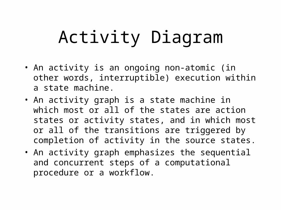
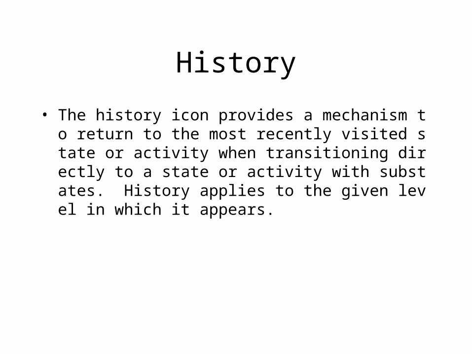
Activity Diagram
• An activity is an ongoing non-atomic (in other words, interruptible) execution within a state machine.
• An activity graph is a state machine in which most or all of the states are action states or activity states, and in which most or all of the transitions are triggered by completion of activity in the source states.
• An activity graph emphasizes the sequential and concurrent steps of a computational procedure or a workflow.
用途An activity graph is a variation of a state machine in which the states represent the performance
of actions or subactivities and the transitions are triggered by the completion of the actions or
subactivities. It represents a state machine of a procedure itself.
• 描述业务模型( Use Case分析)• 描述类动态模型(类设计)
活动图与状态图比较• An activity diagram is a special case of a state diagram in which all (or
at least most) of the states are action or subactivity states and in which all (or at least most) of the transitions are triggered by completion of the actions or subactivities in the source states.
• The entire activity diagram is attached (through the model) to a class, such as a use case, or to a package, or to the implementation of an operation. The purpose of this diagram is to focus on flows driven by internal processing (as opposed to external events).
• Use activity diagrams in situations where all or most of the events represent the completion of internally-generated actions (that is, procedural flow of control).
• Use ordinary state diagrams in situations where asynchronous events occur.
Action state
• An action state is a shorthand for a state with an entry action and at least one outgoing transition involving the implicit event of completing the entry action (there may be several such transitions if they have guard conditions).
• Action states should not have internal transitions or outgoing transitions based on explicit events, use normal states for this situation.
• The normal use of an action state is to model a step in the execution of an algorithm (a procedure) or a workflow process.
Action State
ActivityState
Activity state
• A subactivity state invokes an activity graph. When a subactivity state is entered, the activity graph “nested” in it is executed as any activity graph would be. The subactivity state is not exited until the final state of the nested graph is reached, or when trigger events occur on transitions coming out of the subactivity state.
• Since states in activity graphs do not normally have trigger events, subactivity states are normally exited when their nested graph is finished.
• A single activity graph may be invoked by many subactivity states.
Action-Object Flow
• Actions operate by and on objects. These objects either have primary responsibility for
• initiating an action, or are used or determined by the action. Actions usually specify calls sent
• between the object owning the activity graph, which initiates actions, and the objects that are
• the targets of the actions.
举例
1)选课程计划
2)户籍管理
3)喝咖啡
Component Diagram
A physical, replaceable part of a system that packages
implementation and conforms to and provides the
realization of a set of interfaces.
A component represents a physical piece of implementation of a system, including software code (source, binary or executable) or equivalents such as scripts or command files.
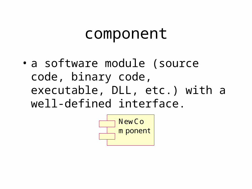
component
• a software module (source code, binary code, executable, DLL, etc.) with a well-defined interface.
NewComponent
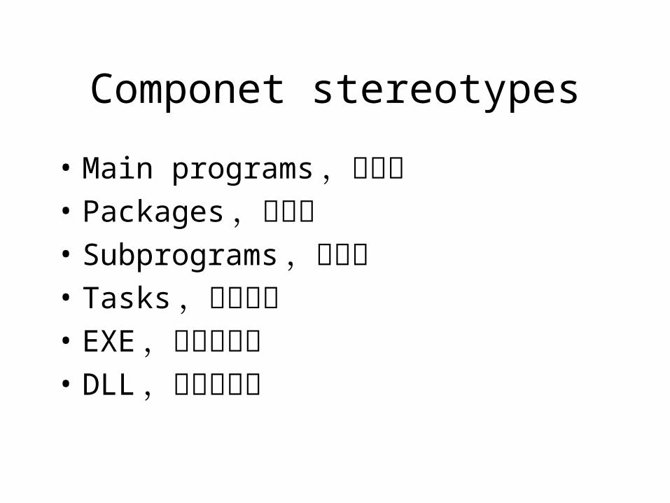
Componet stereotypes
• Main programs,主程序• Packages,构件包 • Subprograms,子程序 • Tasks,独立线程 • EXE,可执行文件 • DLL,动态连接库
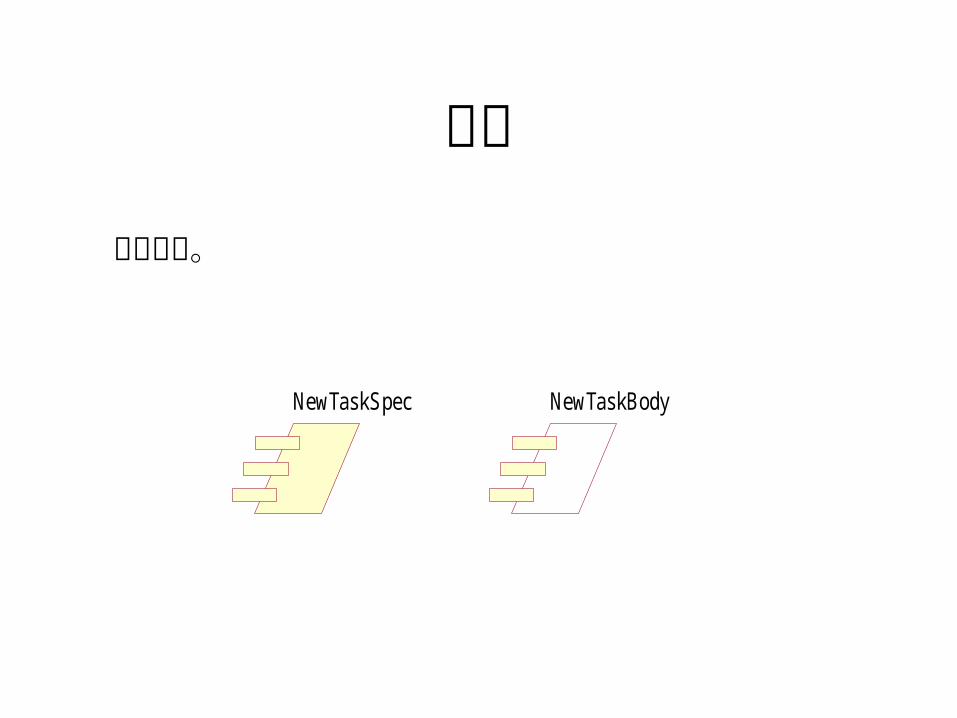
任务
NewTaskSpec NewTaskBody
独立线程。
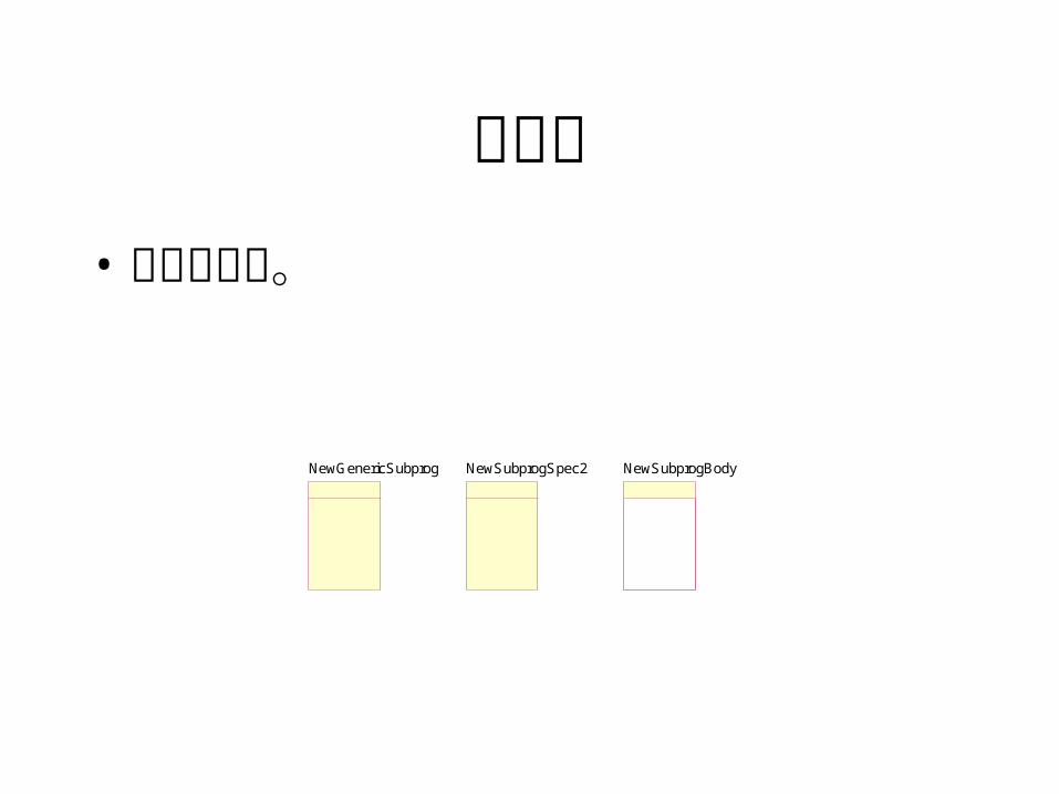
子程序• 不含类声明。
NewSubprogSpec2 NewSubprogBodyNewGenericSubprog
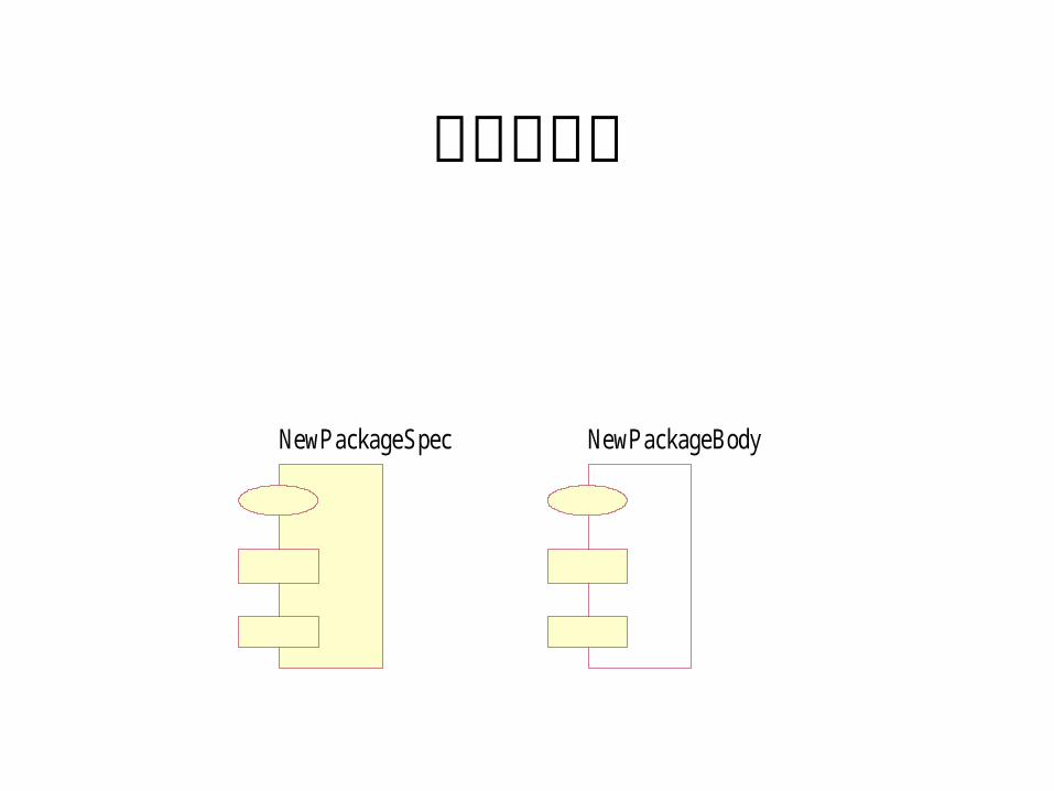
动态链接库
NewPackageSpec NewPackageBody
主程序
NewMainSubprog
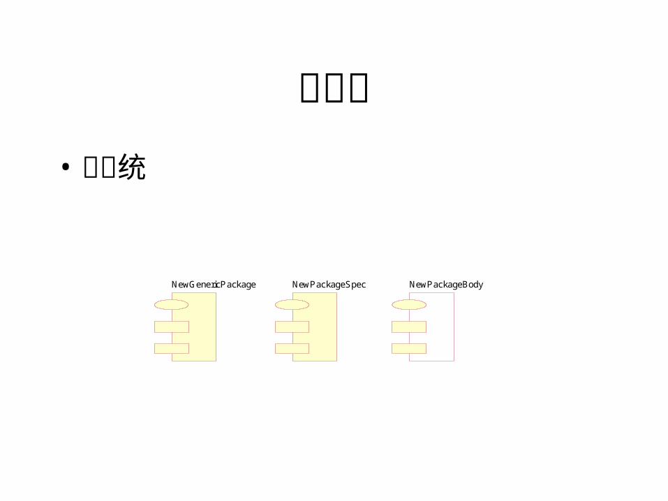
构件包• 子系统
NewPackageSpec NewPackageBodyNewGenericPackage
构件依赖关系• 软件模块的编译和运行时关系。• client component can inherit from, contain instances of, use,
and otherwise depend on classes that are exported from the supplier component.
• You can draw a dependency relationship from a component to an interface of another component, which means that the client component uses the operations of the other component. You can also draw a realize relationship from a component to an interface of another component, which means that the client component provides the operations of the other component.
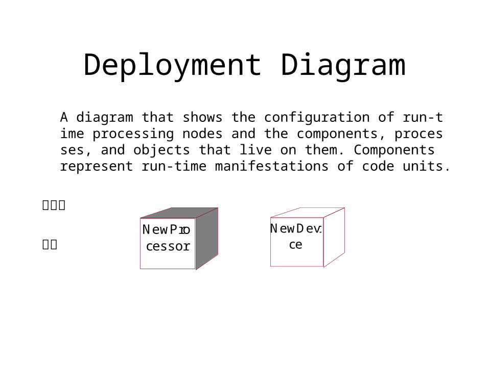
Deployment Diagram
A diagram that shows the configuration of run-time processing nodes and the components, processes, and objects that live on them. Components represent run-time manifestations of code units.
处理机
设备 NewProcessor
NewDevice
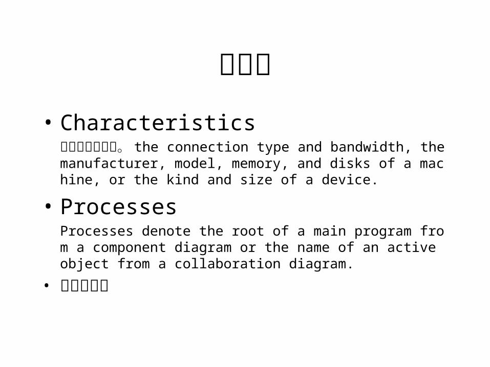
处理机• Characteristics
硬件的物理描述。 the connection type and bandwidth, the manufacturer, model, memory, and disks of a machine, or the kind and size of a device.
• ProcessesProcesses denote the root of a main program from a component diagram or the name of an active object from a collaboration diagram.
• 进程优先级
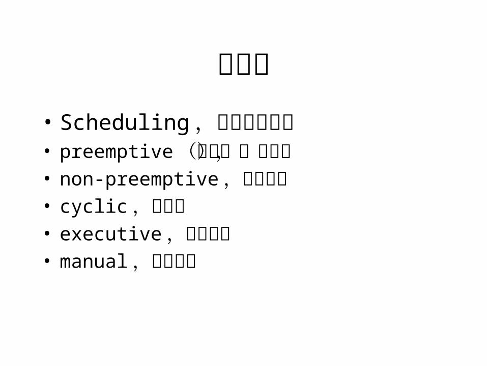
处理机• Scheduling,进程调度方式• preemptive(缺省),抢占式• non-preemptive,非抢占式• cyclic,循环式• executive,算法控制• manual,外部控制
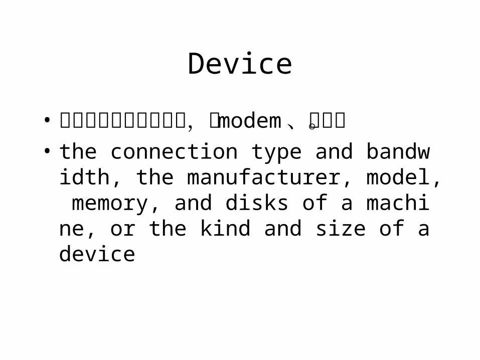
Device
• 无计算能力的外部设备,如 modem、终端。
• the connection type and bandwidth, the manufacturer, model, memory, and disks of a machine, or the kind and size of a device
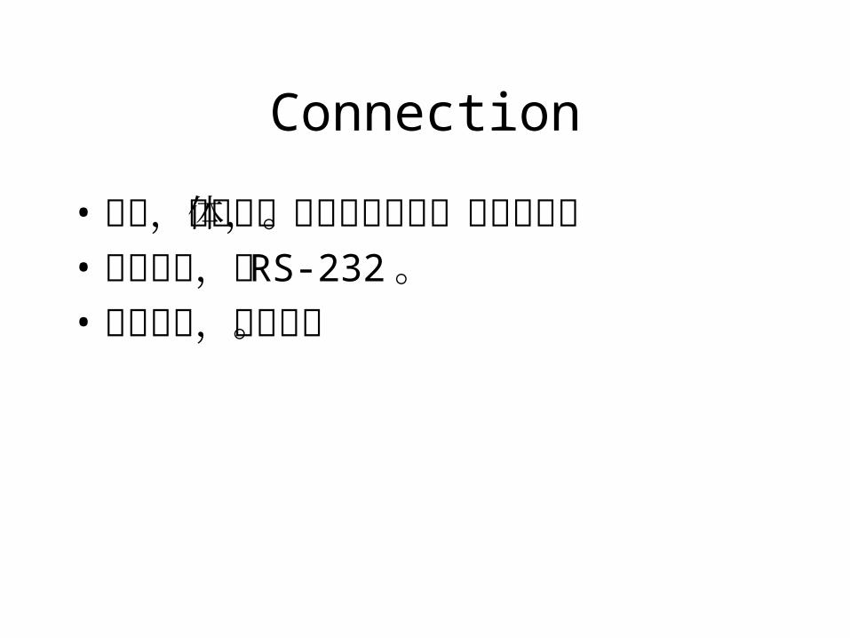
Connection
• 连接,两个实体间的硬件耦合,通信通道。
• 直接连接,如 RS-232。• 间接连接,如卫星。
二、 RUP建模过程与步骤
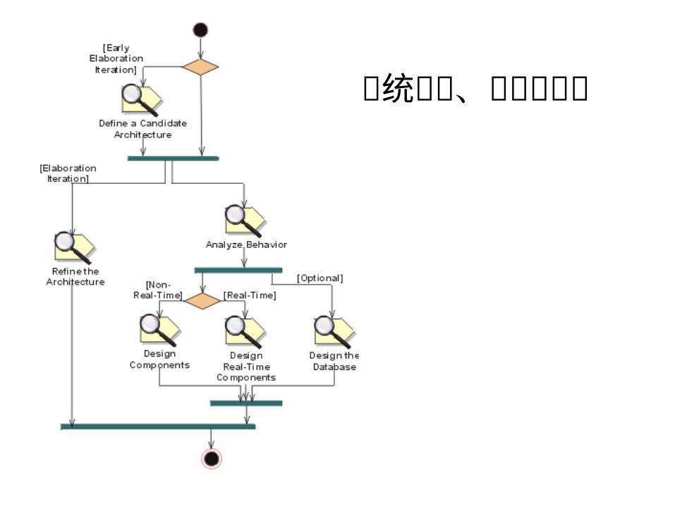
系统分析、设计工作流
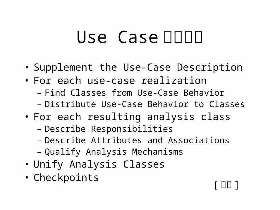
Use Case分析步骤• Supplement the Use-Case Description• For each use-case realization
– Find Classes from Use-Case Behavior– Distribute Use-Case Behavior to Classes
• For each resulting analysis class– Describe Responsibilities– Describe Attributes and Associations– Qualify Analysis Mechanisms
• Unify Analysis Classes• Checkpoints [ 举例 ]
Use Case View
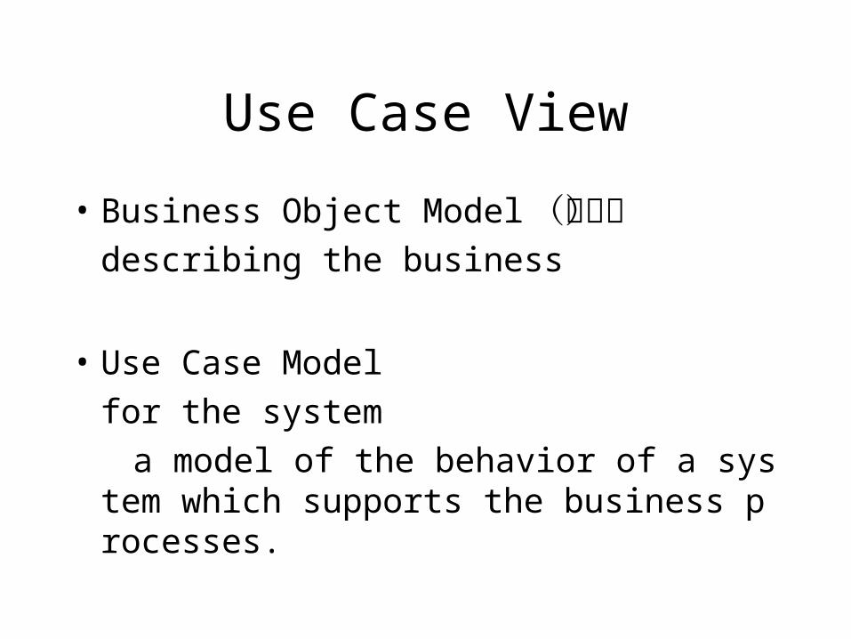
• Business Object Model(可选)describing the business
• Use Case Model
for the system
a model of the behavior of a system which supports the business processes.
Use Case Model
• The Use-Case Model is traceable to (and derives from) the Business Model. The system (as described in the Use Case Model) provides behavior that supports the business.
Use Case package
• Use Case packageAll Use Cases in the system are contained in this package. This is done strictly as a way to organize the model and make it easier to understand.
Use Cases are often documented in a separate text file, use the Rational Unified Process template or use the use case template in Rational Requsite Pro.
The "Use Case Realizations" that correspond to these use cases are created in the Design Model..
Use Case package
• Included Use Cases packagecontains "common" use cases which are textually included in one or more other use cases. They are organized in this package to promote greater reuse.
• Architecturally Significant Use Cases diagramcontains all architecturally significant use cases. <Annotations may be added to the diagram to explain why particular use cases are architecturally significant.>
Actor Package
• Actor packageAll Actors in the system are contained in this package. This is both as a way to organize the model, making it easier to understand, and to provide a way to manage the actors in a single configuration item.
Logical View
• Analysis Model (optional)contains a set of Analysis Classes, which describe an abstract realization of the use cases of the system; evolve into associated design elements which are modeled in the Design Model.
• Business Object Model
• Design Model
Business Object Model• contains a set of interacting workers and business entity (domain) classes whic
h collaborate to enact the business processes. In some cases, only the business entity classes are documented. The business entity classes as a whole are sometimes referred to as a 'domain model'.
• The business modeling workflow in Rational Unified Process produces two models: the business use-case model, and the business object model. Both show the business processes, but different aspects of them. In the business use-case model each business use case represents a business process, described (text and/or activity diagrams) from an "external" view point without worrying about who does what to whom inside of the organization.
• In the business object model, you include realizations of each business use case to show how workers and entities collaborate to perform the process. You do that using class diagrams, activity diagrams with swimlanes, collaboration diagrams, and/or interaction diagrams.
Design Model
• is adapted to model the real implementation environment, and serves as an abstraction of the source code. It is a "blueprint" of how the source code is structured and written.
• The design model is a hierarchy of packages (design subsystems and design-service packages), with "leaves" that are classes. Subsystems are a design "view" of the components that are defined in the Implementation Model.
• The design model hierarchy consists of layers. • Classes represent abstractions of classes in the system's implementation.
They define the objects, which in turn are abstractions of the objects in the system's implementation. The use cases are realized by the objects, and this is represented by use-case realizations in the Design Model. Each use-case realization has a realize dependency to a use case in the Use-Case Model.
Design Model
• Layer
• Process ViewAn architectural view that describes the concurrent aspect of the system: tasks (processes) and their interactions.
• Use Case Realizations
• Architecturally Significant Model Elements
• Architecture Overview - Package, Subsystem Layering
Layer
• The design model is normally organized in layers. The number of layers is not fixed, but varies from situation to situation.
• During architectural analysis, focus is normally on the two high-level layers, that is, the application and business-specific layers; this is what is meant by the "high-level organization of subsystems." The other lower-level layers are in focus during architectural design, refer to the activity Architectural Design for more information.
Layer - package
• A package should be used in cases where a set of classes and/or other packages need to be grouped together for model organization purposes. Though the contents of the package can have public visibility, which makes them visible to model elements outside the containing package, packages are primarily just grouping mechanisms.
• If a set of classes is to be encapsulated and can be hidden behind a well-defined interface, a subsystem is a more appropriate container.
Layer - subsystem
• A subsystem should be used in cases where a set of classes and/or other packages need to be encapsulated within a container and hidden behind a set of well-defined interfaces. By convention, none of the contents of subsystem are visible except the interfaces of the subsystem. This allows subsystems to be easily replaced, and the implementations changed, provided the interfaces remain unchanged. It offers a degree of encapsulation greater than that of the package.
• If a set of classes is merely to be grouped together, but public visibility of classes is still desirable, a package is a more appropriate container.
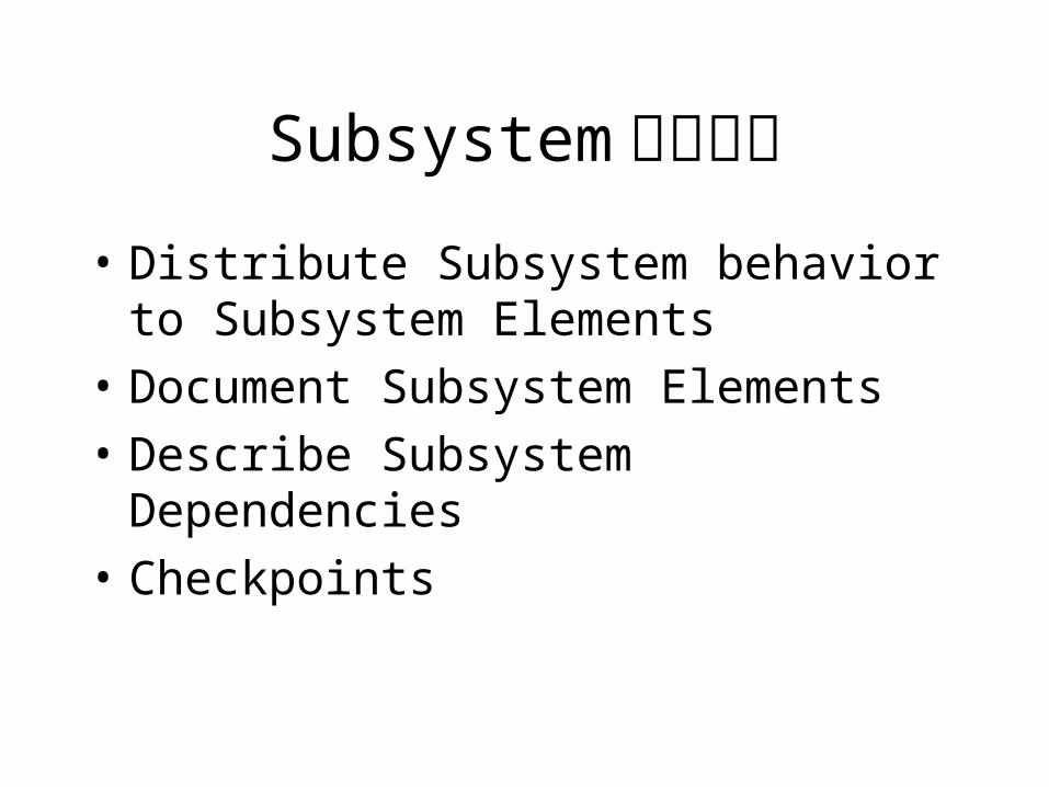
Subsystem设计步骤• Distribute Subsystem behavior to
Subsystem Elements
• Document Subsystem Elements
• Describe Subsystem Dependencies
• Checkpoints
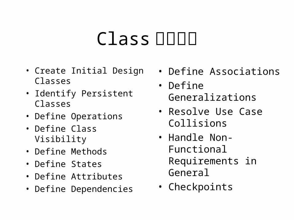
Class设计步骤• Create Initial Design
Classes
• Identify Persistent Classes
• Define Operations
• Define Class Visibility
• Define Methods
• Define States
• Define Attributes
• Define Dependencies
• Define Associations
• Define Generalizations
• Resolve Use Case Collisions
• Handle Non-Functional Requirements in General
• Checkpoints
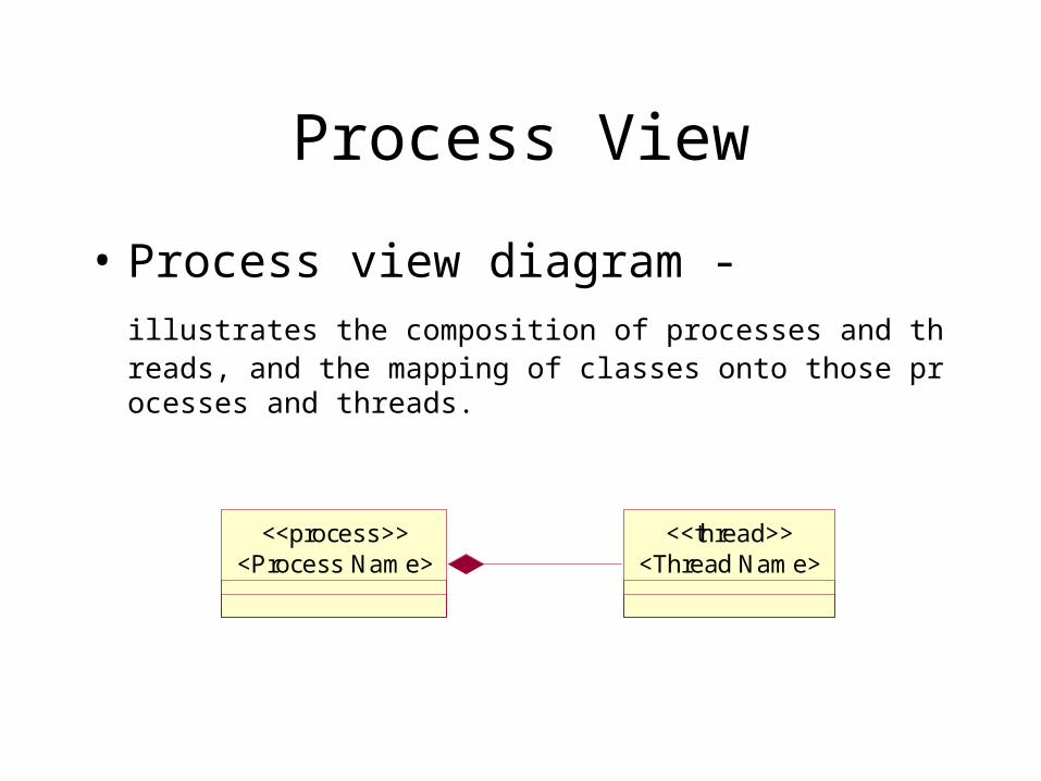
Process View
• Process view diagram - illustrates the composition of processes and threads, and the mapping
of classes onto those processes and threads.
<Process Name><<process>>
<Thread Name><<thread>>
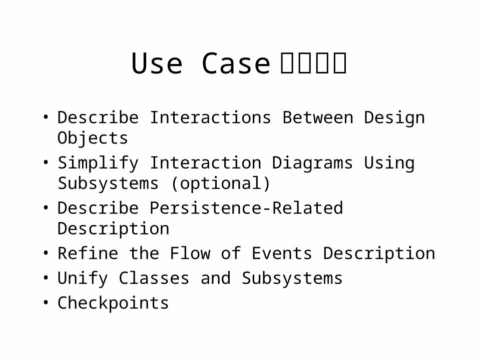
Use Case设计步骤• Describe Interactions Between Design Objects• Simplify Interaction Diagrams Using Subsystems
(optional)• Describe Persistence-Related Description• Refine the Flow of Events Description• Unify Classes and Subsystems• Checkpoints
Use Case Realizations package
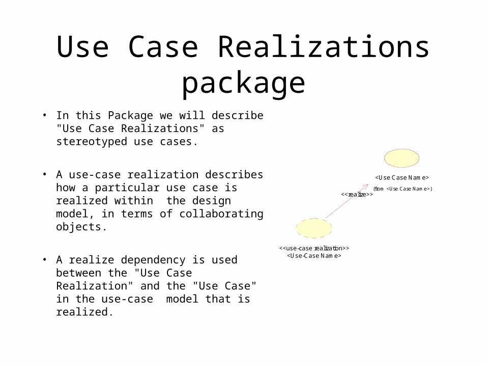
• In this Package we will describe "Use Case Realizations" as stereotyped use cases.
• A use-case realization describes how a particular use case is realized within the design model, in terms of collaborating objects.
• A realize dependency is used between the "Use Case Realization" and the "Use Case" in the use-case model that is realized.
<Use Case Name>
(from <Use Case Name>)
<Use-Case Name><<use-case realization>>
<<realize>>
Use Case Realization
• Participating classes diagram
• realize dependicies
• Sequence Diagram
basic type, other flow type
Component View
• Implementation Modelis a collection of components, and the implementation subsystems that contain them.
An architectural view that describes one or several system configurations; the mapping of software components (tasks, modules) to the computing nodes in these configurations.Defines executables, dlls, files, subsystems, compilation order etc.
It is recommended that, in most cases, the mapping should be1:1 between design and implementation, that is, for each package in design there is one subsystem in the implementation model.
Deployment View
• Defines the typical physical network configurations, including those typically used by end users, as well as special configurations used for development and test.
• Allocate processes to the various nodes. Allocation takes into account the capacity of the nodes (in terms of
both memory and processing), bandwidth of the communication medium (bus, LANs, WANs), and the
availability of the hardware and communication links, rerouting, and so on.
三、讨论
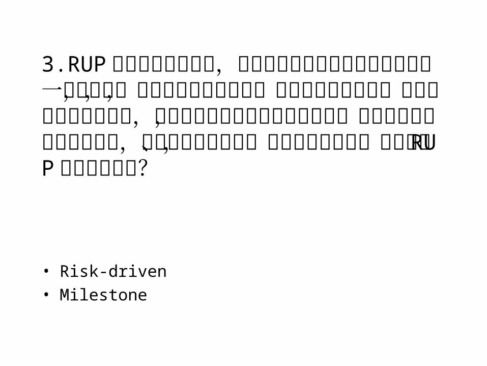
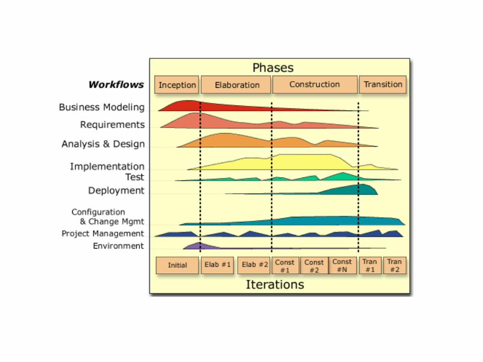
3.RUP 的方法是迭代式的,是不是可以理解为软件开发时先做一个简单的,实现基本功能的软件,然后再不断的改进,但是以前的开发过程中,有些情况应该首先将界面设计好,然后在编写业务代码的同时,同步进行使用手册、产品演示等工作,如果采用 RUP 应该如何协调?
• Risk-driven
• Milestone
4. 我觉得完全按照 Rose 的各种框图设计太繁琐了,能不能推荐一种简化的方案?
应动静结合,不能随意简化,否则对系统的认识不完整,最终以说清楚为准。
可参考 Rose RUP Framework。
5.Rose 的中文化问题 ,哪些对象的命名可用中文 ?如 Sequence 图中的 Message 命名
是否不能用中文 ?
业务模型、抽象类,不影响代码生成的图形元素均可以。
6.Sequence 图与 Class 图是否是同时生成并交互修改 ?
1)严格地说,一上来就画静态结构(类图)不对,静态结构是为动态模型完成的功能服务的,所以应该先有需求阶段的顺序图(动态模型),后有静态模型,这是因果关系。2)类模型中有边界类、控制类和实体类。实体类是客观存在的,所以在需求阶段的静态结构中,主要是指实体类(即业务对象)和重要的边界类、控制类(但一般是抽象类)。3)顺序图有两种分别在 Use Case View和 Logical View中出现,用途不同,都可能修改,类图应随之变化。
7. 请列举出运用 Rose 系列工具进行软件开发的全过程。
• RUP
9. 生成的代码中能不能体现 Use Case 图中顺序图所展示出来的业务流程 ?
Rose Real Time模型本身可以执行。将来 Rose也可以在模型中加入代码。
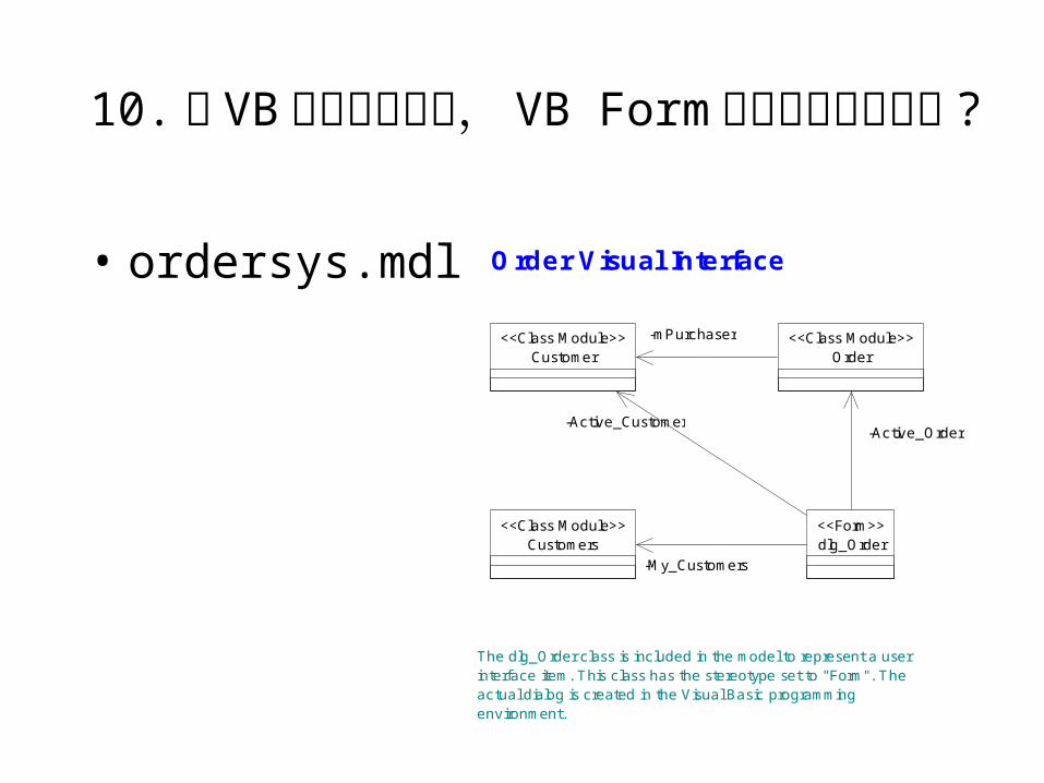
10. 在 VB 语言的模型中, VB Form 如何在模型中实现 ?
• ordersys.mdl O rder Visual Interface
The dlg_O rder class is included in the m odel to represent a user interface item . This class has the stereotype set to "Form ". The actual dialog is created in the Visual Basic program m ing environm ent.
O rder<<Class M odule>>
Custom er<<Class M odule>> -m Purchaser
Custom ers<<Class M odule>>
dlg_O rder<<Form >>
-Active_O rder-Active_Custom er
-M y_Custom ers
11.Stereotype 的不同类型如何在模型中体现?
• A stereotype is, in effect, a new class of modeling element that is introduced at modeling time. It represents a subclass of an existing modeling element with the same form (attributes and relationships) but with a different intent. Generally a stereotype represents a usage distinction.
• A stereotyped element may have additional constraints on it from the base class. It may also have required tagged values that add information needed by elements with the stereotype. It is expected that code generators and other tools will treat stereotyped elements specially.
• Stereotypes represent one of the built-in extensibility mechanisms of UML.
自定义 stereotype
• Stereotypes allow you to provide additional distinctions in your model that are not explicitly supported by the UML metamodel. Stereotypes extend the basic modeling elements to create new elements. This makes it easier to add information about modeling elements that may be specific to a project or process.
• A diagram icon (.wmf, .emf)• A small diagram toolbar icon (.bmp)• A large diagram toolbar icon• A list view icon (.bmp)
Stereotype 配置文件• A stereotype configuration file defines a set of stereotypes, including t
he location of icon files as well as settings that affect the usage and display of the defined stereotypes. Typically, the extension of a stereotype configuration file is .ini, but any extension is allowed.
• Each stereotype configuration file needs to be located in the Rational Rose installation folder, defined by the InstallDir registry value, and listed in the StereotypeCfgFiles registry section.
• Note: It is recommended that you add any new stereotypes to the default stereotype configuration file, DefaultStereotypes.ini.
• Below is a sample configuration file. The sample displays all of the available settings, but the default settings are typically all you need. Select a setting for an explanation of its possible values.
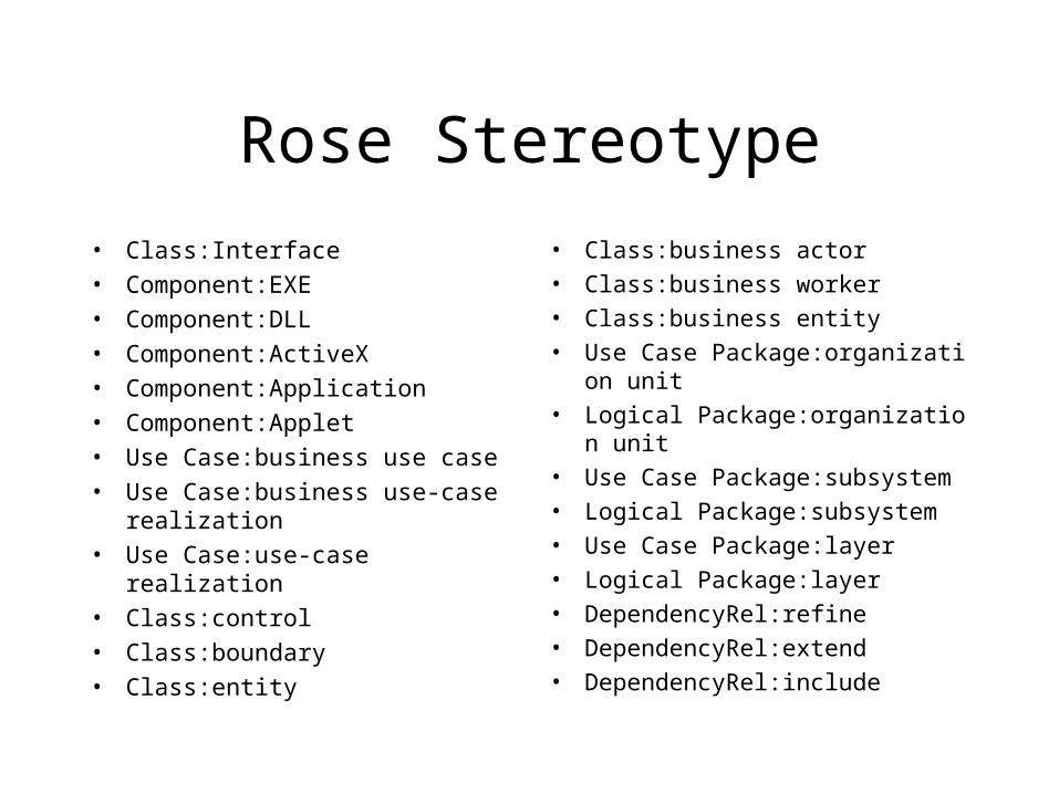
Rose Stereotype
• Class:Interface• Component:EXE• Component:DLL• Component:ActiveX• Component:Application• Component:Applet• Use Case:business use case• Use Case:business use-case
realization• Use Case:use-case realization• Class:control• Class:boundary• Class:entity
• Class:business actor• Class:business worker• Class:business entity• Use Case Package:organization unit• Logical Package:organization unit• Use Case Package:subsystem• Logical Package:subsystem• Use Case Package:layer• Logical Package:layer• DependencyRel:refine• DependencyRel:extend• DependencyRel:include
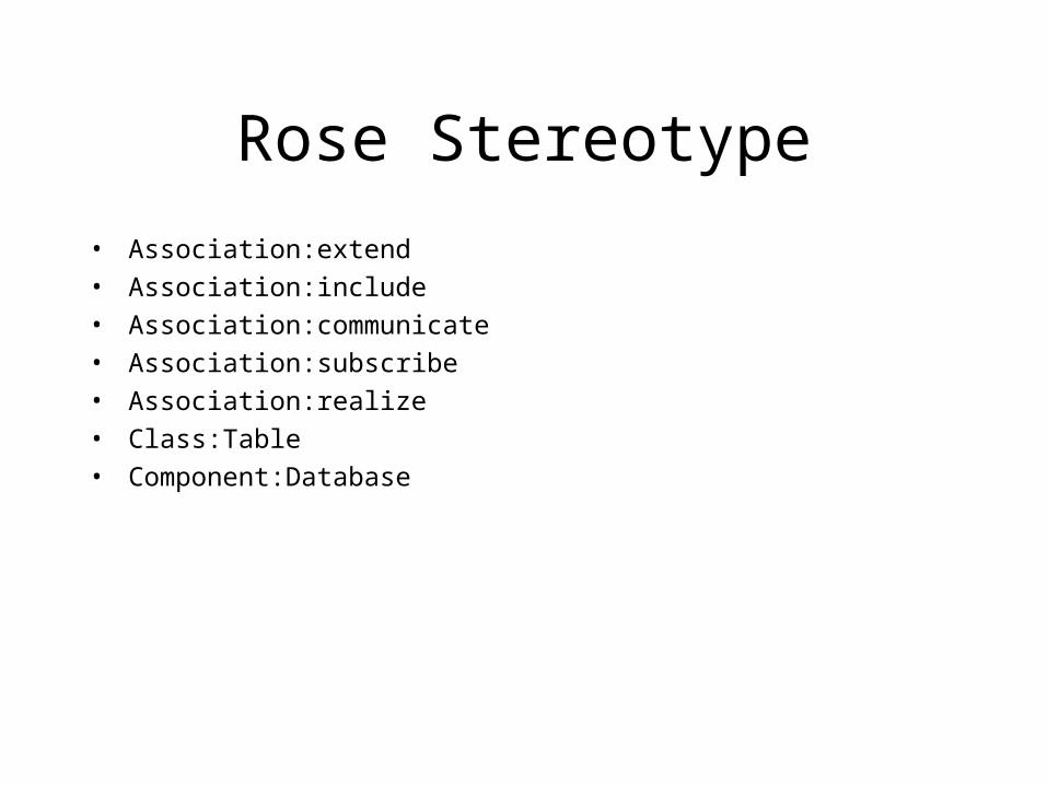
Rose Stereotype
• Association:extend
• Association:include
• Association:communicate
• Association:subscribe
• Association:realize
• Class:Table
• Component:Database
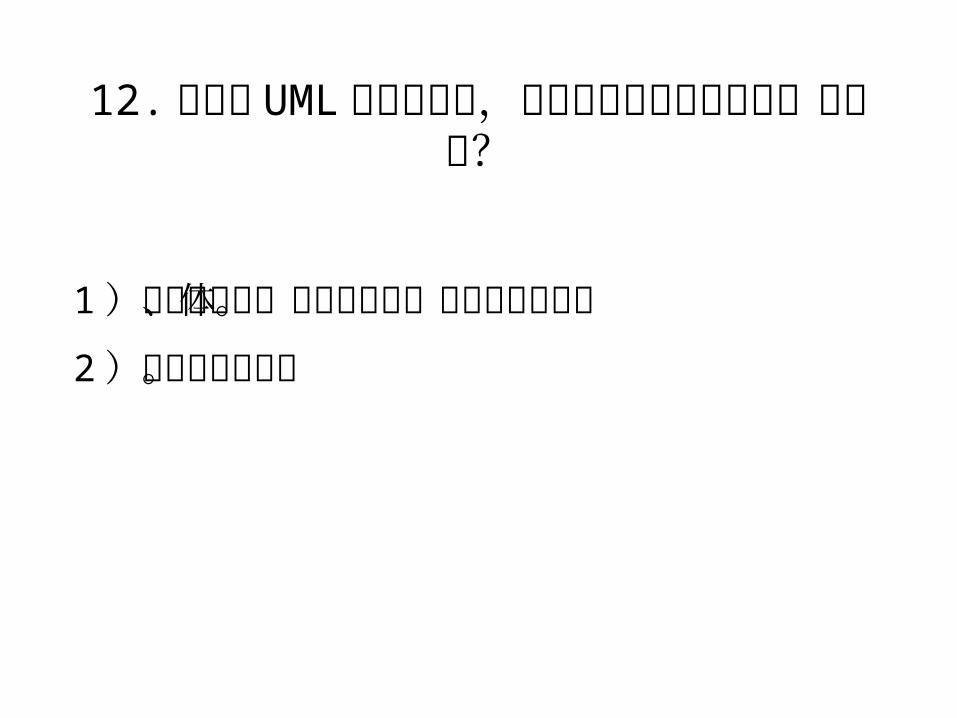
12. 在建立 UML 模型过程中,如何才能更好地发现系统中的类?
1)根据边界类、控制类和实体类的划分思考。
2)参考设计模式。
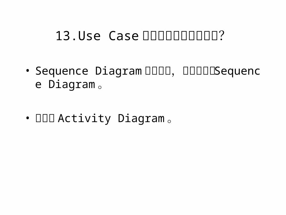
13.Use Case 中的条件分支如何表示?
• Sequence Diagram中用注释,或分成多个 Sequence Diagram。
• 直接用 Activity Diagram。
1. 能否给出一个使用 rose 开发的项目的文档实例?
SoDA 文档模版。
2. 使用 ROSE 如何进行界面设计 ,采用 rose 设计时如何与一些可视化的控件联系起
来 ?
以 Delphi应用设计为例。


![[科技產業]UA intro](https://img.pdfslide.tips/doc/110x75/55c6273fbb61eb12108b4641/ua-intro.jpg)