Embed Size (px)
Citation preview

Overview and Current Status

DEVELOPMENT OF TWO TYPES OF TUBULAR SOFCS AT TOTO
Akira Kawakami, Satoshi Matsuoka, Naoki Watanabe, Takeshi Saito, Akira Ueno TOTO Ltd. Chigasaki, Kanagawa 253-8577 Japan
Tatsumi Ishihara Kyushu University Higashi, Nishi 8 19-0395 Japan
Natsuko Sakai, Harumi Yokokawa National Institute of Advanced Industrial Science and Technology (AIST) Tsukuba, Ibaraki 305-8565 Japan
ABSTRACT
developed lOkW class tubular SOFC modules for stationary power generation using Japanese town gas (13A) as fuel. A small module which consisted of 5 stacks (a stack consisted of 2 x 6 cells) generated 1.5kW at 0.2Alcm2 and achieved 55%-LHV efficiency at an average temperature of 900°C. A thermally self-sustaining module consisting of 20 stacks achieved 6.5kW at 0.2A/cm2 and 50%-LHV.
relatively lower temperatures. The single cell generated 0.85,0.70, and 0.24W/cm2 at 700"C, 600"C, and 500°C, respectively. We built and evaluated a stack consisting of 14 micro tubular cells, and it successfully demonstrated 43W. 37W and 28W at a temperature of 700°C, 600°C, and 500°C. respectively.
INTRODUCTION TOTO is the top sanitary ware manufacturer in Japan and highly experienced in
traditional and advanced ceramic products. Solid Oxide Fuel Cells (SOFCs) are mainly composed of ceramics, and our fabrication technology has been utilized to produce high performance SOFCs at a low cost. TOTO started the research and development of tubular type SOFCs in 1989. From 2001 to 2004, we successfully completed a lOkW class thermally self- sustaining module test in a New Energy and Industrial Technology Development Organization (NEDO) project'). Since 2004, TOTO started a new collaboration with Kyushu Electric Power Co., Inc. and Hitachi, Ltd. in a new NEDO project. We are developing a co-generation system by integration with the TOTO stack. On the other hand, TOTO also started the development of micro SOFCs using micro tubular cells (diameter is less than 5mm) from 2002 under another NEDO project. In this paper, we summarized the current status of two types of SOFCs R & D at TOTO, i.e. tubular SOFC for stationary power generation and micro tubular SOFC for portable power application.
TOTO TUBULAR SOFC Cell development
The schematic viewgraphs of the TOTO tubular cell are shown in Figure 1. A perovskite cathode tube is formed by extrusion molding. A zirconia electrolyte and a nickelizirconia cermet
The current status of two types of SOFC R & D at TOTO is summarized. We have
We have also developed micro tubular SOFCs for portable application, which operate at
3
Advances in Solid Oxide Fuel Cells I1 Narottam P. Bansa
Copyright 0 2007 by the American Ceramics Societ)
Development of Two Types of Tubular SOFCs at TOTO
Components Cathode Tube
Electrolyte Anode
Interconnector
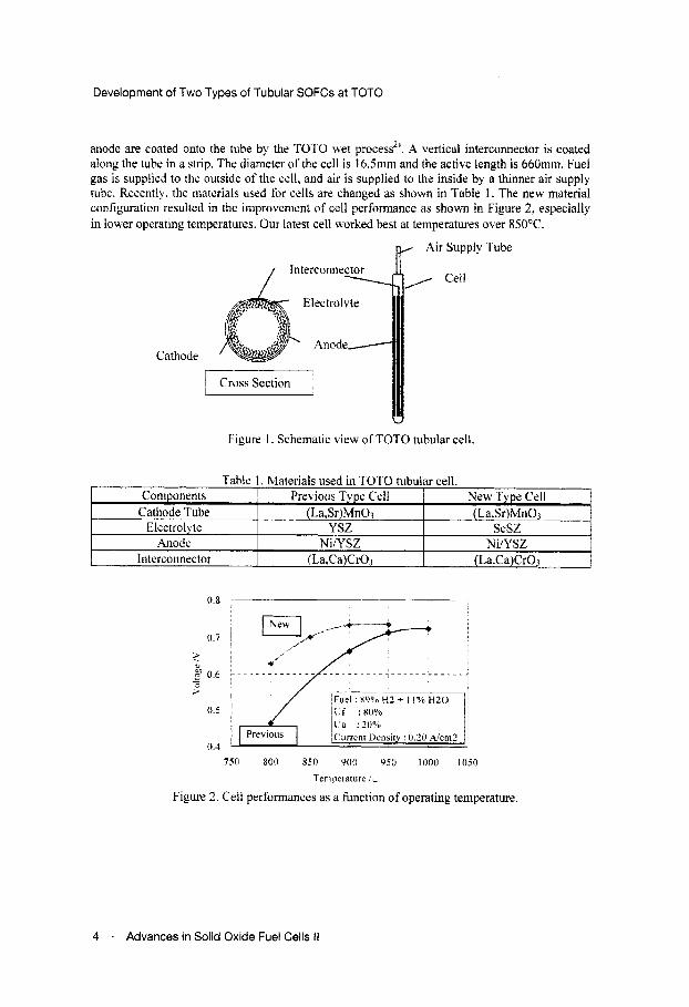
anode are coated onto the tube by the TOTO uet process”. A vertical interconnector is coated along the tube in a strip. The diameter of the cell i s 16Smm and the active length is 66Omm. Fuel gas is supplied to the outside of the cell, and air is supplied to the inside by a thinner air supply tuhe. Recently. the materials used for cells are changed as shown in Table 1. The neu material configuration resulted in the improvenient of cell performance as shown in Figure 2. especially in lov.er operating temperatures. Our latest cell worked best at temperatures over 850°C.
p Air Supply Tube
Previous Type Cell New Type Cell (La,Sr)MnOi (La.Sr)MnOj
YSZ scsz NiiYSZ Ni/YSZ
(La,Ca)CrOj (La,Ca)CrOa
Cathode
U
Figure 1. Schematic view of TOTO tubular cell.
0.7
?
0.5
0.4
7.50 800 850 900 950 1000 1050
Temperature 1-
Figure 2 . Cell performances as a function of operating temperature.
4 . Advances in Solid Oxide Fuel Cells II

Development of Two Types of Tubular SOFCs at TOTO
Stack development Twelve tubes are bundled in a 2x6 stack with nickel materials connecting an
interconnector of one cell and the anode o f the next (Figure 3). A stack was installed in a metal casing and heated by an electric furnace. Simulated fuel of partially steam reformed toMn gas w’as supplied to the stack. The town gas was assumed to be 50% steam reformed under SIC (steam carbon ratio) -3.0. A stack generated 0.34kW at a current density of 0.2A/ cm2 at a temperature of 940°C. The maximum efficiency for DC output of the stack mas 57%-Lower Heating Value (LHV) calculated on the basis ofequijalent town gas (Figure 4).
Figure 3. Appearance o f TOTO stack. Figure. 4 Perfomiance of 2x6 stack.
Small module (quarter size module) The thermally self-sustaining operation indicates that the modules generate power
without any external heat supply. A quarter-size small size modules. which consisted of 5 stacks were made and tested for hasic ekaluations to realize the thermally self-sustaining operation. The small module and its metal casing here c o w e d with a ceramic insulator. In this test, the desulfurized town gas was partially steam refonlied through a reactor. The reformer was installed outside of the module with an electric furnace as shown in Figure 5. The conversion of steam
Figure 5. Flow diagram of small SOFC module.
Advances in Solid Oxide Fuel Cells I I - 5
Development of Two Types of Tubular SOFCs at TOT0
reforming can be controlled independently with reformer temperature. However the higher hydrocarbons such as ethane (C2Flh). propane (C3Hs) and butane (CJHIO) were coinpletely converted. The residual CH4 was internally reformed on the anode, and the endothermic effect was utilized to maintain the homogeneous temperature distribution of the module. The outlet fuel and air were mixed and bumed above the module, and this combustion heat was used for air pre- heating. Those improvements in temperature distribution and fuel gas distribution strongly affected on the module performance. We succeeded to operate a module with 1.6kW at 0.2A/cm2 at an average temperature of 900°C which corresponds to the effkiency of40%-LHV for 3000 hours. The maximum efficiency was 55 %- LHV. which obtained for different module.
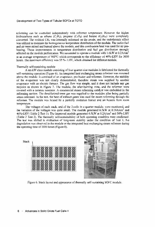
Themially self-sustaining module A ten kW class module consisting of four quarter-size modules is fabricated for thermally
self-sustaining operation (Figure 6). An integrated heat exchanging steam reformer was mounted above the module. It consisted of an evaporator, pre-heater and reformer. However, the stability of the evaporator was not clearly demonstrated, therefore steam was supplied by another evaporator with an electric f m c e . The gas flow was simple, and it does not include any gas recycles as shown in Figure 7. The module, the after-burning zone, and the reformer were covered with a ceramic insulator. A conimercial steam reforming catalyst was embedded in the reforming section. The desulfurized town gas was supplied to the modules after being partially steam reformed. In the test. the heat of exhaust gases was used for steam refonning through the reformer. The module was heated by a partially oxidation burner and air heaters from rooni temperature.
The voltages of each stack. and of the 2-cells in a quarter module, w-ere monitored. and the variation of the voltages was quite small. The module generated 6.5kW at 0.19A/cmZ and 46%-LHV (Table 2 Test 1 ). The improved module generated 6.5kW at 0.2A/cm2 and 50%-LHV (Table 2 Test 2). The themially self-sustainability of both operating condition were confirmed. The test was shifted to evaluation of long-term stability under the condition of Test 1 . No degradation was observed in the module or the integrated heat exchanging steam reformer during the operating time of 1000 hours (Figure 8).
Figure 6. Stack layout and appearance of thermallj self-sustaining SOFC module.
6 . Advances in Solid Oxide Fuel Cells II

Development of Two Types of Tubular SOFCs at TOT0
Figure 7. Flow diagram of thermally self-sustaining SOFC, module system.
Items Test 1 Test 2 Power(kW
0.19 0.20 0.69 0.70
1000
0
Efficiency
Purrent Densit)
0 120 240 360 480 600 720 840 960 1080 Timeih
100
0
Figure 8. Long term stabilitj of thermally self-sustaining SOFC module.
Advances in Solid Oxide Fuel Cells II . 7

Development of Two Types of Tubular SOFCs at TOTO
Component Anode Tube
Anode Interlayer
Electrolyte
Cathode
Material Fabrication Firing NiO/YSZ Extrude Molding
NiOiGDC 10 Co-Firing
LSCF Firing
LDC~O(G~ZO~)-LSGM sluny coating (Double Layered)
8 . Advances in Solid Oxide Fuel Cells II
Development of Two Types of Tubular SOFCs at TOTO
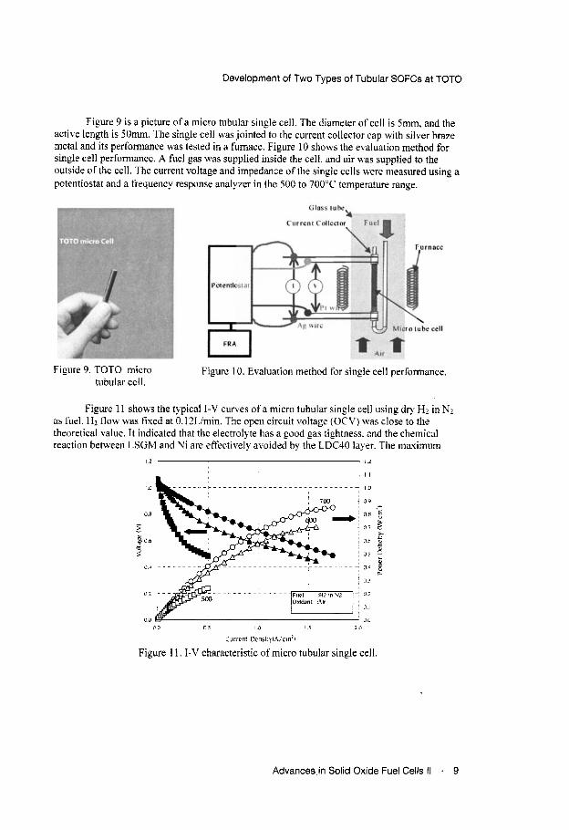
Figure 9 is a picture of a micro tubular single cell. The diameter of cell is 5mm, and the acthe length is 5 0 m . The single cell was jointed to the current collector cap with silver braze metal and its performance was tested in a furnace. Figure 10 shows the evaluation method for single cell performance. A fuel gas was supplied inside the cell, and air was supplied to the outside of the cell. The current voltage and impedance ofthe single cells were measured using a potentiostat and a frequency response analyzer in the 500 to 700°C temperature range.
Figure 9. TOTO micro Figure 10. Evaluation method for single cell performance. tubular cell.
Figure 11 s h o w the typical I-V curves ofa micro tubular single cell using dry Hz in Nz as fuel. Hz flow was fixed at 0.12Limin. The open circuit voltage (OCV) was close to the theoretical value. It indicated that the electrolyte has a good gas tightness. and the chemical reaction between LSGM and Ni are effectively avoided by the LDC40 layer. The mavimum
I 2 I .2
I 1
I 0
O D - 0 6 .E
05 : 04 g
9 F i 5
0.b >
0.3
0.2
0.1
00 0 0 i'i I (1 1 5 20
Current t km i t ) iA , cin21
Figure 11. I-V characteristic of micro tubular single cell.
Advances in Solid Oxide Fuel Cells II . 9

Development of Two Types of Tubular SOFCs at TOT0
power densities were 0.85.0.70, and 0.24W/cm2 at 700"C, 600°C. and 500°C. respectively. Figure 12 shows the impedance spectra o f a micro tubular cell measured under 0.125A/cmz at various teniperatures. It has been generally assumed that the intercept with the real-axis at the highest frequency represents the ohmic resistance. and the aidth of low frequency arc represents the electrode resistance. The electrode resistance increased significantly with decreasing operation temperature. and ohmic resistance at 500°C was very high. The most likely cause of the high resistance is the low ionic conductivitj ofI,DC40. Therefore, it is expected that the cell performance can be improved by optimizing the anode electrode and the thickness of LDC40 layer.
under 0.125Aicm' at 700°C and 600°C. The observed cell voltage was close to the theoretical value calculated by the Nernst equation. It indicates that the micro tubular cell can be operated at a high efficiency.
Figure 13 shows the fuel utilization effects on micro tubular cell performance measured
Figure 12. Impedance of micro tubular
..
..
..
? >
cell
I
0 9
,.. 2 0.8
f j 0.7
g
0.0
0.5
(100
................................
' H2 i i l N 2
Ciirrctil iknsity: J I l 5 h ' c m Z
0 20 40 60 80 I W
FttI'I Utilivatlon (a4
Figure 13. Fuel utilization effect on micro tubular cell performance.
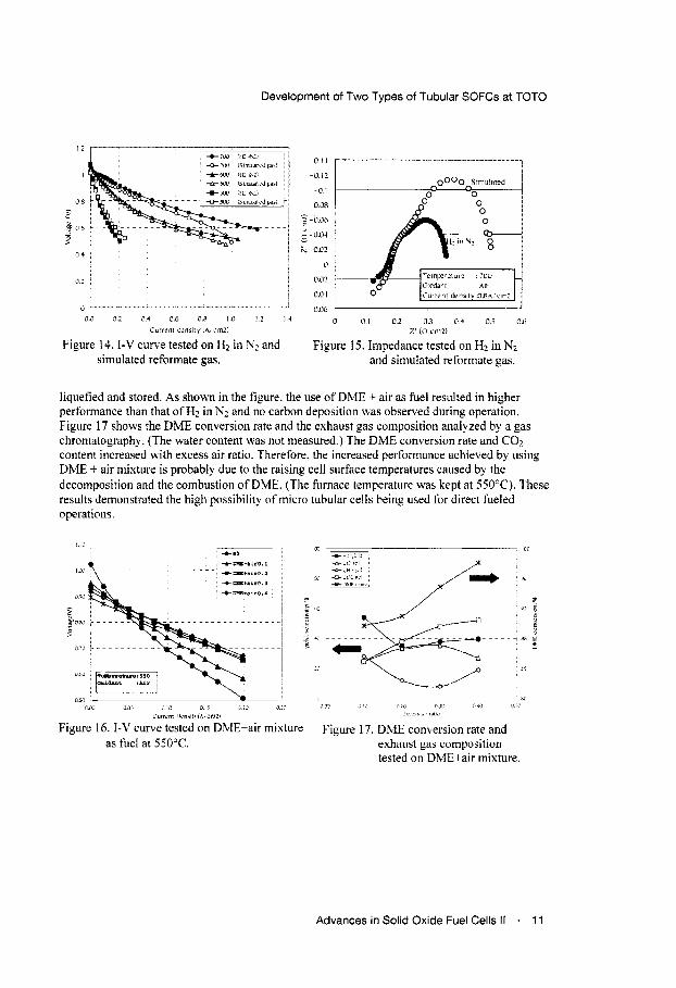
The cell performances using H2 in Nz ( 1: I ) gas mixture or simulated reformate gas were compared in Figure 14. The composition of simulated reformate was 32%l-tzl 13%CO. 5%CO2, and 500/0N2 based on the preliminary experiment of the catalytic partial oxidation (CPOX) reforming of LPG. As shown in the figure. the difference in cell performances was small at lower current densities. However, the perfomiance using reformate gas was lower at higher current densities at temperatures of 600°C and 700°C. The differences became significant with increasing operating temperatures. To identi5 the differences, the impedance spectra were measured under a current density of 0.8A/cniz at 700°C (Figure 15). The electrode resistance on simulated reformate was higher than that on Hz in N1, and it was thought that this diffrrence was caused hy the CO transport resistance from the anode in the high current density area. Therefore. we are now trying to improve the anode performance.
DME flow rate was fixed at 85mL'min and the excess air ratios (air-fuel ratio/ theoretical air-fuel ratio) were 0.1,0.2,0.3. and 0.4 respectively. Direct use of fuel without a refonner in SOFCs will simplify the system greatly. and this is important for SOFCs. especially in portable and transportation applications. DME is an attractive fuel because it is highly active and easily
Figure16 shows the cell performance using DME: + air mixture as fuel at 550°C. The
10 . Advances in Solid Oxide Fuel Cells II
Development of Two Types of Tubular SOFCs at TOT0
-0.14
-0.12
-0.1
-OUR
5 -fl.06
6 - 0.04 - k -002
11
OD?
0.04
0Ob
0 111 02 02 0 4 0 5 06 LIC 111 114 06 O R I 0 1 2 1 4
Current drn,ltyhcrm2) Z ' m cm21
Figure 14. I-V curve tested on H2 in NL and Figure 15. Impedance tested on Hl in N2 and simulated reformate gas. siniulated reforinate gas.
liquefied and stored. As shown in the figure. the use of DME + air as fuel resulted in higher performance than that of H2 in Nz and no carbon deposition was observed during operation. Figure 17 shows the Dh4E conversion rate and the exhaust gas composition analyzed by a gas chromatography. (The water content was not measured.) The DME conversion rate and C02 content increased with excess air ratio. Therefore. the increased performance achieved by using DME + air nlixturr is probably due to the raising cell surface temperatures caused by the decomposition and the combustion of DME. (The furnace temperature wa5 kept at 550°C). These results demonstrated the high possibility of micro tubular cells being used for direct fueled operations
iurrilnt t c n ~ t w cmzi
Figure 16. I-V curve tested on DME+air mixture Figure 17. DME conbersion rate and as fuel at SSOOC. exhaust gas composition
tested on DME+air mixture.
Advances in Solid Oxide Fuel Cells II . 11

Development of Two Types of Tubular SOFCs at TOT0
Micro tubular stack development
14 micro tubular cells as shown in Figure1 8. This stack was evaluated in a furnace using hydrogen as a fuel. and successfully demonstrated 43W, 37W and 28W power generation at a temperature of 700"C, 600°C. and 500°C, respectively (Figure19). Table 4 summarizes the results we have obtained from the stack evaluation. The maximum stack power densities were 478WIL and 239W/bg at 700°C. These results demonstrated that micro tubular SOFCs have a high potential for portable and transportation applications.
In order to evaluate the performance of cells in a bundle, we built the stack consisting of
, i
1.6 ~
!
0.4 1
...
...
80
60
40 CI
20
0 - 0 0 0 0 2 0 4 0 6 o a 10
Ctirrcnt dcnsity (A/cin2)
Figure 19. Performance of micro tubular SOFC stack.
12 . Advances in Solid Oxide Fuel Cells II

Development of Two Types of Tubular SOFCs at TOTO
Table 4. Performance of micro tubular SOFC stack at 7OOOC. Result
SUMMARY TOTO tubular SOFC
The 2x6 stack, small module and thermally self-sustaining module of the TOTO tubular SOFC were designed and made. They were evaluated using town gas or simulated fuel and showed excellent performance. We continually improve the cell performance and the durability to advance the module performance. TOTO started the small-scale production of SOFC and trial delivery in 2004. The SOFC can be supplied as a stack for the development of stationary power generation systems. In 2004, TOTO started a new collaboration with Kyushu Electric Power Co., Inc. and Hitachi, Ltd. in a new NEDO project. We are developing a co-generation system by integration with the TOTO stack.
TOTO micro tubular SOFC The anode-supported micro tubular cells with thin lanthanum gallate with strontium and
magnesium doping were developed. The single cells and the cell stack were tested using various fuels, i.e. hydrogen, simulated reformate gas of LPG, direct fueling of DME, and they showed excellent performance at lower temperatures from 500-700°C. These results demonstrated that micro tubular SOFCs have a high potential for portable and transportation applications. Further development on durability, quick start up, and compactness of the stack is being undertaken.
ACKNOWLEDGMENT The development was supported by NEDO in Japan.
REFERENCES ‘T. Saito, T. Abe, K.Fujinaga, M. Miyao, M. Kuroishi, K. Hiwatashi, A. Ueno, “Development of
Tubular SOFC at TOTO’, SOFC-IX, Electrochemical Society Proceedings Volume 2005-07, 133- 140(2005) 2K. Hiwatashi, S.Furuya, T. Nakamura, H. Murakami, M. Shiono. M. Kuroishi, “Development Status
of Tubular type SOFC by Wet Process”, Proc. of the 12“’Symposium on Solid Oxide Fuel Cells in Japan, 12- 15(20031
J. Van herle, J. Sfeir, R. Ihringer, N. M. Sammes, G. Tompsett, K. Kendall, K. Yamada, C. Wen, M. Ihara, T. Kawada and J. Mizusaki, “ Improved Tubular SOFC for Quick Thermal Cycling”, Proc. of the Fourth Europeay Solid Oxide Fuel Cell Forum, 251-260 (2000)
A. Kawakami, S. Matsuoka, N. Watanabe, A. Ueno, T. Ishihara, N. Sakai, K. Yamaji, H. Yokokawa, “Development of low-temperature micro tubular type SOFC‘‘, Proc. of the 1 3Ih Symposium on Solid Oxide Fuel Cells in Japan, 54-57(2004)
conductor”, J.Am.Chem.Soc, I16,3801-3803 (1994)
672 (1 994)
Cells Using New Anode Materials”, J.Electrochem.Soc, 148(7), A788-A794 (2001)
5T. Ishihara, H. Matsuda, Y . Takita, “Doped LaGaO, perovskite type oxide as a new oxide ionic
6M.Feng, J.B.Goodenough, “A superior oxide-ion electrolyte”, Eur.J.Solid State Inorg.Chem.,3 1,663-
K. Huang, J.H Wan, J.B.Goodenough, “Increasing Power Density o f LSGM-Based Solid Oxide Fuel
Advances in Solid Oxide Fuel Cells II . 13