Embed Size (px)
Citation preview

USER'S GUIDE
EDSA®
ELECTRICAL DISTRIBUTION AND TRANSMISSION SYSTEMS ANALYSES AND DESIGN PROGRAMS
COMPUTATION OF SAG & TENSION
OR SPAN LENGTH
FOR A CONDUCTOR SUSPENDED
BETWEEN TWO SUPPORTS
WINDOWS
EDSA MICRO CORPORATION 11440 West Bernardo Court
Suite 370 San Diego, California 92127
U.S.A.
© Copyright 2003 All Rights Reserved
Version 1.00.00 August 2003

EDSA MICRO CORPORATION
WARRANTY INFORMATION
There is no warranty, implied or otherwise, on EDSA software. EDSA software is licensed to you as is. This program license provides a ninety (90) day limited warranty on the diskette that contains the program. This, the EDSA User’s Guide, is not meant to alter the warranty situation described above. That is, the content of this document is not intended to, and does not, constitute a warranty of any sort, including warranty of merchantability or fitness for any particular purpose on your EDSA software package. EDSA Micro Corporation reserves the right to revise and make changes to this User's Guide and to the EDSA software without obligation to notify any person of, or provide any person with, such revision or change. EDSA programs come with verification and validation of methodology of calculation based on EDSA Micro Corporation's inhouse software development standards. EDSA performs longhand calculation and checks the programs’ results against published samples. However, we do not guarantee, or warranty, any program outputs, results, or conclusions reached from data generated by any programs which are all sold "as is". Since the meaning of QA/QC and the verification and validation of a program methodology are domains of vast interpretation, users are encouraged to perform their own inhouse verification and validation based on their own inhouse quality assurance, quality control policies and standards. Such operations - performed at the user's expense - will meet the user's specific needs. EDSA Micro Corporation does not accept, or acknowledge, purchase instructions based on a buyer's QA/QC and/or a buyer's verification and validation standards. Therefore, purchase orders instructions are considered to be uniquely based on EDSA's own QA/QC verification and validation standards and test systems. TRADEMARK EDSA is a trademark of EDSA Micro Corporation. COPYRIGHT © Copyright 1989 - 2003 by EDSA Micro Corporation. Please accept and respect the fact that EDSA Micro Corporation has enabled you to make an authorized disk as a backup to prevent losing the contents that might occur to your original disk drive. DO NOT sell, lend, lease, give, rent or otherwise distribute EDSA programs / User's Guides to anyone without prior written permission from EDSA Micro Corporation. All Rights Reserved. No part of this publication may be reproduced without prior written consent from EDSA Micro Corporation.

Version Control Record
Date Version Description May 1997 1.00.00 First windows version release
i

ii
USER'S GUIDE
EDSA®
ELECTRICAL DISTRIBUTION AND TRANSMISSION
SYSTEMS ANALYSES AND DESIGN PROGRAMS
COMPUTATION OF SAG AND TENSION
OR SPAN LENGTH
FOR A CONDUCTOR SUSPENDED
BETWEEN TWO SUPPORTS
WINDOWS
TABLE OF CONTENTS
I. FOREWORD page 1
II. INTRODUCTION page 1
III. OBJECTIVE page 1
IV. CAPABILITIES page 1
V. PROGRAM THEORY page 2
5.1 SUPPORTS AT SAME ELEVATIONS page 2
5.2. SUPPORTS AT DIFFERENT ELEVATIONS page 3
VI. HOW TO RUN THE PROGRAM page 4
6.1 EXAMPLES: SAG & TENSION page 6
6.2 EXAMPLES: SPAN LENGTH page 16
VII. REFERENCES page 24
Tutorial Exercise
1.0 Sag and Tension Calculations page 28
2.0 Span Calculations page 35
DIAGRAMS
I. Figure 1 page 2
II. Figure 2 page 3

EDSA
COMPUTATION OF SAG&TENSION OR SPAN LENGTH
Page 1
I. FOREWORD This program assumes the user is a Professional Engineer familiar with the concepts of computation of sag &
tension or span length of a conductor suspended between two supports. Determination of validity of the results, and whether the COMPUTATION OF SAG & TENSION or SPAN LENGTH program is applicable to a system, is the user's responsibility.
The COMPUTATION OF SAG & TENSION or SPAN LENGTH program is being continuously improved in
the attempt to make it as comprehensive and easy to use as possible. Additional analyses capabilities will be made available as they are developed. Any comments, suggestions or errors encountered in either the results or documentation should be immediately brought to EDSA's attention.
II. INTRODUCTION The design of a wire span requires solutions to the following problems:
At what tension must the wire be strung under a given weather condition (erection condition) such that the tension in the span does not exceed a definite limit under the worst weather condition? What are the sags and other quantities of interest under both the given and the worst weather conditions? What are the sag, tension, and other important quantities under different weather conditions? The design of a wire span suspended between two supports at the same elevations, or at different elevations having a vertical separation, also involves finding the length of the span corresponding to a specified tension and sag, or vertical separation of the lowest point of the catenary curve from the upper support under a specific weather condition.
This program is a very useful tool for the practicing power system engineers and designers who need to quickly determine the sag and tension of a wire span or the length of a wire span.
III. OBJECTIVE This program provides an easy and operative method of calculating the sag and tension in wire spans, and also
provides an easy, usable method for calculating the length of wire spans. IV. CAPABILITIES The program has the capability of computing the sag and tension in wire spans, or the length of wire spans,
under the following options: Span type: a. Supports at same elevations; b. Supports at different elevations. System of units: a. English system (U.S. Standard); b. Metric system. Accuracy control: a. Default tolerance;
b. User provided tolerance.

EDSA
COMPUTATION OF SAG&TENSION OR SPAN LENGTH
Page 2
Catenary lowest point type:
a. On the span; b. Outside the span.
V. PROGRAM THEORY Since a conductor suspended between two supports assumes the shape of a catenary curve, this program uses
the catenary method of sag and tension calculation in order to obtain the most accurate results. The calculation involves the solution of non-linear equations containing hyperbolic functions. Most of the calculation is done in the double precision method for maximum accuracy.
The program is designed using the following methodology: For a given wire span with its conductor-specified weather conditions, and one specified tension
under this first condition, the program calculates all the important quantities of interest under both conditions. (Please note: when each support is at a different elevation, the tension is at the upper support.)
The following notes are very important regarding the procedure to be used to get the solutions:
(i) Corresponding to the first condition, a value of the horizontal component of tension is obtained, and it satisfies the specified tension within the specified tolerance. Once this horizontal tension value is obtained, the other quantities of interest occurring under the first weather condition are determined.
(ii) Corresponding to the temperature of the second condition, the unstressed length of the
conductor is determined. The value of the tension horizontal component, which satisfies this unstressed length within the specified tolerance, is thus obtained. Once the horizontal tension is obtained, the other quantities under the second weather condition are determined.
For finding the data for the sags, tensions, and any other important items, for different loadings or weather
conditions, the program is to be rerun, changing the input data for the second condition only. 5.1 SUPPORTS AT THE SAME ELEVATIONS A conductor suspended between two supports at same elevations is shown in Fig.1.
Fig.1 Conductor Suspended Between Supports at Same Elevations

EDSA
COMPUTATION OF SAG&TENSION OR SPAN LENGTH
Page 3
5.2 SUPPORTS AT DIFFERENT ELEVATIONS A model of a conductor span between supports at different elevations is shown in Fig.2. In this figure, the
conductor is acted on by a resultant force containing a horizontal component and a vertical component.
Fig.2 Model of Conductor Span Between Supports at Different Elevations.

EDSA
COMPUTATION OF SAG&TENSION OR SPAN LENGTH
Page 4
VI. HOW TO RUN THE PROGRAM
The following abbreviations are used in all examples and in the output: System of units: English (U.S. Standard) pound lb, feet ft, inch in, square inch in2, degree 0F; System of units: Metric kilogram Kg, meter m, centimeter cm, square centimeter cm2, degree 0C.
1. Select “Analysis” from the EDSA Window Main Menu. 2. Select “Transmision Line Sag & Tension”.

EDSA
COMPUTATION OF SAG&TENSION OR SPAN LENGTH
Page 5
After starting the program Computation of Sag & Tension or Span Length, the first step is to either create a
new project file, or open an existing one. This is done via the FileOpen or FileNew command shown above. Selecting FileNew will bring up the “Settings for Sag & Tension or Span Length” screen shown below.

EDSA
COMPUTATION OF SAG&TENSION OR SPAN LENGTH
Page 6
Information should be entered using the following steps:
1. Press “Add”. The cursor will automatically move to “Span ID”. 2. Assign a “Span ID”. 3. Press the “Tab” key to move to the “Description” field. 4. Complete “Description”. 5. Check your selection for:
• “Sag & Tension” or “Span Length” calculation; • “Metric” or “US Standard” units; and • “Aluminum” or “Copper” material.
6. “Nominal Size” may be selected from a picklist by checking the “Select” button. 7. The use of the “Tab” key to progress through the remaining data fields assures entry of all necessary
items in a logical sequence. “Condition 1” and “Condition 2” dialog boxes must also be completed. 8. IMPORTANT!! Be sure to use “Save As” to save all information.
If you select FileOpen from the Computation of Sag & Tension or Span Length program main menu, you will be prompted to select the file to open as shown on the screen below:
QA/QC files are located in C:\EDSAWIN\SAMPLES or C:\EDSAWIN\JOBS, or, if you are custom installed,
wherever you directed the program load them at setup. It is our strong recommendation to take a moment to get familiar with the existing QA/QC files, and develop a firm understanding of them prior to the building of your own file. At the same time, take a moment to test all commands and icons (e.g. File, View, Window, Help, etc.), so that you acquaint yourself with their functions.
6.1 EXAMPLES: SAG & TENSION
From the above shown screen, select “test.stc”. This file has four spans and calculates Sag & Tension.
EDSA
COMPUTATION OF SAG&TENSION OR SPAN LENGTH
Page 7
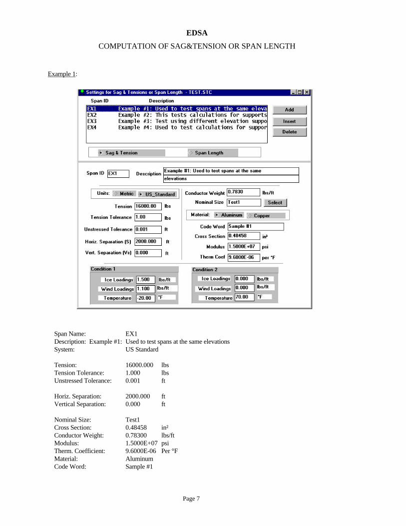
Example 1:
Span Name: EX1 Description: Example #1: Used to test spans at the same elevations System: US Standard Tension: 16000.000 lbs Tension Tolerance: 1.000 lbs Unstressed Tolerance: 0.001 ft Horiz. Separation: 2000.000 ft Vertical Separation: 0.000 ft Nominal Size: Test1 Cross Section: 0.48458 in² Conductor Weight: 0.78300 lbs/ft Modulus: 1.5000E+07 psi Therm. Coefficient: 9.6000E-06 Per °F Material: Aluminum Code Word: Sample #1

EDSA
COMPUTATION OF SAG&TENSION OR SPAN LENGTH
Page 8
Condition 1 Condition 2 Ice Loadings: 1.500 lbs/ft 0.000 lbs/ft Wind Loadings: 1.100 lbs/ft 0.000 lbs/ft Temperature: -20.000 °F 70.000 °F Condition 1 Horizontal Component of Tension: 15795.4392 lbs Stressed Conductor Length: 2008.5911 ft Unstressed Conductor Length: 2004.2075 ft Sag in the Plane of the Conductor: 80.3911 ft Vertical Component of the Sag: 72.4228 ft Mismatch in Tension: -8.349736E-01 lbs Condition 2 Horizontal Component of Tension: 5259.3300 lbs Stressed Conductor Length: 2007.3964 ft Unstressed Conductor Length: 2005.9391 ft Sag in the Plane of the Conductor: 74.5767 ft Vertical Component of the Sag: 74.5767 ft Tension at the Support: 5317.7236 lbs Mismatch in Unstressed Length: -5.522255E-04 ft Example 2 :

EDSA
COMPUTATION OF SAG&TENSION OR SPAN LENGTH
Page 9
Span Name: EX2 Description: Example #2: This tests calculations for supports at the same elevations. System: Metric Tension: 277.000 Kg Tension Tolerance: 1.000 Kg Unstressed Tolerance: 0.001 m Horiz. Separation: 45.700 m Vertical Separation: 0.000 m Nominal Size: Test2 Cross Section: 0.13200 cm² Conductor Weight: 0.11560 Kg/m Modulus: 1.6632E+05 Kg/cm² Therm. Coefficient: 1.6600E-05 Per °C Material: Copper Code Word: Sample #2 Condition 1 Condition 2 Ice Loadings: 0.000 Kg/m 0.000 Kg/m Wind Loadings: 0.200 Kg/m 0.000 Kg/m Temperature: 4.500 °C 32.200 °C Condition 1 Horizontal Component of Tension: 276.9497 Kg Stressed Conductor Length: 45.7028 m Unstressed Conductor Length: 45.1262 m Sag in the Plane of the Conductor: 0.2178 m Vertical Component of the Sag: 0.1090 m Mismatch in Tension: -9.136259E-06 Kg Condition 2 Horizontal Component of Tension: 266.0879 Kg Stressed Conductor Length: 45.7008 m Unstressed Conductor Length: 45.1469 m Sag in the Plane of the Conductor: 0.1134 m Vertical Component of the Sag: 0.1134 m Tension at the Support: 266.1010 Kg Mismatch in Unstressed Length: -1.046679E-04 m
EDSA
COMPUTATION OF SAG&TENSION OR SPAN LENGTH
Page 10
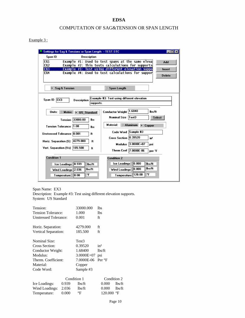
Example 3 :
Span Name: EX3 Description: Example #3: Test using different elevation supports. System: US Standard Tension: 33000.000 lbs Tension Tolerance: 1.000 lbs Unstressed Tolerance: 0.001 ft Horiz. Separation: 4279.000 ft Vertical Separation: 185.500 ft Nominal Size: Test3 Cross Section: 0.39520 in² Conductor Weight: 1.68400 lbs/ft Modulus: 3.0000E+07 psi Therm. Coefficient: 7.0000E-06 Per °F Material: Copper Code Word: Sample #3 Condition 1 Condition 2 Ice Loadings: 0.939 lbs/ft 0.000 lbs/ft Wind Loadings: 2.036 lbs/ft 0.000 lbs/ft Temperature: 0.000 °F 120.000 °F
EDSA
COMPUTATION OF SAG&TENSION OR SPAN LENGTH
Page 11
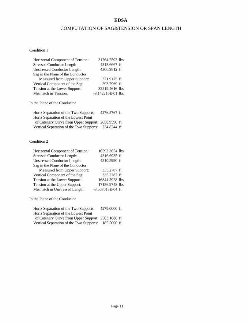
Condition 1 Horizontal Component of Tension: 31764.2503 lbs Stressed Conductor Length 4318.6667 ft Unstressed Conductor Length: 4306.9812 ft Sag in the Plane of the Conductor, Measured from Upper Support: 371.9175 ft Vertical Component of the Sag: 293.7969 ft Tension at the Lower Support: 32219.4616 lbs Mismatch in Tension: -8.142210E-01 lbs In the Plane of the Conductor Horiz Separation of the Two Supports: 4276.5767 ft Horiz Separation of the Lowest Point of Catenary Curve from Upper Support: 2658.9590 ft Vertical Separation of the Two Supports: 234.8244 ft Condition 2 Horizontal Component of Tension: 16592.3654 lbs Stressed Conductor Length: 4316.6935 ft Unstressed Conductor Length: 4310.5990 ft Sag in the Plane of the Conductor, Measured from Upper Support: 335.2787 ft Vertical Component of the Sag: 335.2787 ft Tension at the Lower Support: 16844.5928 lbs Tension at the Upper Support: 17156.9748 lbs Mismatch in Unstressed Length: -3.507013E-04 ft In the Plane of the Conductor Horiz Separation of the Two Supports: 4279.0000 ft Horiz Separation of the Lowest Point of Catenary Curve from Upper Support: 2563.1688 ft Vertical Separation of the Two Supports: 185.5000 ft

EDSA
COMPUTATION OF SAG&TENSION OR SPAN LENGTH
Page 12
Example 4 :
Span Name: EX4 Description: Example #4: Used to test calculations for supports at different elevations. System: Metric Tension: 27482.000 Kg Tension Tolerance: 1.000 Kg Unstressed Tolerance: 0.001 m Horiz. Separation: 822.900 m Vertical Separation: 54.600 m Nominal Size: Test4 Cross Section: 2.55000 cm² Conductor Weight: 2.93200 Kg/m Modulus: 4.1477E+06 Kg/cm² Therm. Coefficient: 7.0000E-06 Per °C Material: Copper Code Word: Sample #4 Condition 1 Condition 2 Ice Loadings: 1.339 Kg/m 0.000 Kg/m Wind Loadings: 1.966 Kg/m 0.000 Kg/m Temperature: 0.000 °C 120.000 °C

EDSA
COMPUTATION OF SAG&TENSION OR SPAN LENGTH
Page 13
Condition 1 Horizontal Component of Tension: 27198.6469 Kg Stressed Conductor Length: 825.4006 m Unstressed Conductor Length: 823.2705 m Tension at the Lower Support: 27198.6938 Kg Mismatch in Tension: -6.978451E-01 Kg In the Plane of the Conductor Horiz Separation of the Two Supports: 822.5161 m Horiz Separation of the Lowest Point of Catenary Curve from Upper Support: 833.2606 m Vertical Separation of the Two Supports: 60.1069 m **** Lowest Point of the Catenary Curve is Outside the Span **** Condition 2 Horizontal Component of Tension: 17690.1597 Kg Stressed Conductor Length: 825.3459 m Unstressed Conductor Length: 823.9621 m Sag in the Plane of the Conductor, Measured from Upper Support: 54.6114 m Vertical Component of the Sag: 54.6114 m Tension at the Lower Support: 17690.1931 Kg Tension at the Upper Support: 17850.2803 Kg Mismatch in Unstressed Length: -6.982306E-04 m In the Plane of the Conductor Horiz Separation of the Two Supports: 822.9000 m Horiz Separation of the Lowest Point of Catenary Curve from Upper Support: 811.1730 m Vertical Separation of the Two Supports: 54.6000 m

EDSA
COMPUTATION OF SAG&TENSION OR SPAN LENGTH
Page 14
Select ViewResults, ViewReport, or ViewProperties.
Sample ViewResults.

EDSA
COMPUTATION OF SAG&TENSION OR SPAN LENGTH
Page 15
Sample ViewReport. Please try all commands (i.e.: File, Edit, Search, Help).
Sample ViewProperties. Conductor List has the capability to “Add”, “Insert”, or “Delete” information from a picklist
library.
EDSA
COMPUTATION OF SAG&TENSION OR SPAN LENGTH
Page 16
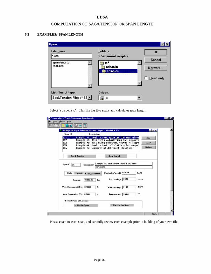
6.2 EXAMPLES: SPAN LENGTH
Select “spanlen.stc”. This file has five spans and calculates span length.
Please examine each span, and carefully review each example prior to building of your own file.

EDSA
COMPUTATION OF SAG&TENSION OR SPAN LENGTH
Page 17
Example 1 :
Span Name: EX1 Description: Example #1: Used to test spans at the same elevations System: US Standard Tension at the Support: 16000.000 lbs Sag in the Vertical Plan: 72.000 ft Conductor Weight: 0.78300 lbs/ft Ice Loadings: 1.500 lbs/ft Wind Loadings: 1.100 lbs/ft Temperature: -20.000 °F Output Results Horiz. Separation of the Supports: 1994.2326 ft Horiz. Component of Tension: 15797.4637 lbs Sag in the Conductor Plan: 79.9168 ft

EDSA
COMPUTATION OF SAG&TENSION OR SPAN LENGTH
Page 18
Example 2 :
Span Name: EX2 Description: Example #2: This tests calculations for supports at the same elevations. System: Metric Tension at the Support: 266.000 Kg Sag in the Vertical Plan: 0.113 m Conductor Weight: 0.11560 Kg/m Ice Loadings: 0.000 Kg/m Wind Loadings: 0.000 Kg/m Temperature: 32.200 °C Output Results Horiz. Separation of the Supports: 265.9869 Kg Sag in the Conductor Plan: 0.1130 m

EDSA
COMPUTATION OF SAG&TENSION OR SPAN LENGTH
Page 19
Example 3 :
Span Name: EX3 Description: Example #3: Test using different elevation supports. System: US Standard Tension at the Support: 33000.000 lbs Sag in the Vertical Plan: 294.000 ft Vertical Seperation: 185.500 ft Conductor Weight: 1.68400 lbs/ft Ice Loadings: 0.939 lbs/ft Wind Loadings: 2.036 lbs/ft Temperature: 0.000 °F Tolerance Factor: 1.00 % Lowest Point of Catenary: On the Span Output Results Horiz. Component of Tension: 31764.2108 lbs Tension at Lower Support: 32220.1988 lbs Tension at Upper Support: 32999.9229 lbs Mismatch in Tension at Upper Support: -0.0770376 lbs

EDSA
COMPUTATION OF SAG&TENSION OR SPAN LENGTH
Page 20
In the Vertical Plan: Horiz. Separation of the Supports: 4281.2027 ft Vert. Separation of Lowest Point from the Upper Support: 293.9817 ft Mismatch in Vertical Seperation of Lowest Point from Upper Support: -0.0183 ft In the Conductor Plan: Horiz. Separation of the Supports: 4278.7807 ft Vert. Separation of the Supports: 234.8244 ft Vert. Separation of Lowest Point from the Upper Support 372.1514 ft Horiz. Separation of Lowest Point from the Upper Support: 2659.7880 ft Example 4 :

EDSA
COMPUTATION OF SAG&TENSION OR SPAN LENGTH
Page 21
Span Name: EX4 Description: Example #4: Used to test calculations for supports at different elevations. System: Metric Tension at the Support: 27481.000 Kg Sag in the Vertical Plan: 54.600 m Vertical Seperation: 54.600 m Conductor Weight: 2.93200 Kg/m Ice Loadings: 1.339 Kg/m Wind Loadings: 1.966 Kg/m Temperature: 0.000 °C Tolerance Factor: 1.00 % Lowest Point of Catenary: On the Span Output Results Horiz. Component of Tension: 27198.3917 Kg Tension at Lower Support: 27198.3917 Kg In the Vertical Plan: Horiz. Separation of the Supports: 833.5666 m In the Conductor Plan: Horiz. Separation of the Supports: 833.1876 m Vert. Separation of the Supports: 60.1069 m Vert. Separation of Lowest Point from the Upper Support: 60.1069 m Horiz. Separation of Lowest Point from the Upper Support: 833.1876 m
EDSA
COMPUTATION OF SAG&TENSION OR SPAN LENGTH
Page 22
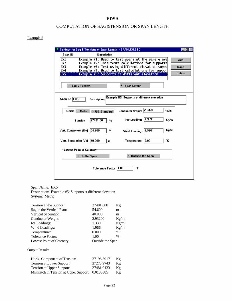
Example 5
Span Name: EX5 Description: Example #5: Supports at different elevation System: Metric Tension at the Support: 27481.000 Kg Sag in the Vertical Plan: 54.600 m Vertical Seperation: 40.000 m Conductor Weight: 2.93200 Kg/m Ice Loadings: 1.339 Kg/m Wind Loadings: 1.966 Kg/m Temperature: 0.000 °C Tolerance Factor: 1.00 % Lowest Point of Catenary: Outside the Span Output Results Horiz. Component of Tension: 27198.3917 Kg Tension at Lower Support: 27273.9743 Kg Tension at Upper Support: 27481.0133 Kg Mismatch in Tension at Upper Support: 0.0133385 Kg

EDSA
COMPUTATION OF SAG&TENSION OR SPAN LENGTH
Page 23
In the Vertical Plan: Horiz. Separation of the Supports: 402.4710 m Vert. Separation of Lowest Point from the Upper Support: 54.6026 m Mismatch in Vertical Seperation of Lowest Point from Upper Support: 0.0026 m In the Conductor Plan: Horiz. Separation of the Supports: 402.0496 m Vert. Separation of the Supports: 44.0343 m Vert. Separation of Lowest Point from the Upper Support: 60.1097 m Horiz. Separation of Lowest Point from the Upper Support: 833.2073 m

EDSA
COMPUTATION OF SAG&TENSION OR SPAN LENGTH
Page 24
VII. REFERENCES 1. Dwight, H.B., "Sag Calculations for Transmission Lines", Transactions A.I.E.E., May, 1926. 2. Freeman, P.J., "Electric Power Transmission & Distribution", Harrap & Co. Ltd., London, 1974. 3. Gonen, Turan, "Electric Power Transmission System Engineering:Analysis and Design", John Wiley
& Sons, 1988. 4. Woodruff, L.F., "Electric Power Transmission", John Wiley & Sons Inc., 1938.

EDSA
COMPUTATION OF SAG&TENSION OR SPAN LENGTH
Page 25
Tutorial Exercise
This tutorial will illustrate how to conduct sag, tension and span calculations for suspended power conductors. The program has the following analysis capabilities:
Sag and Tension Analysis
- Calculates all mechanical forces for supports placed at equal or different elevations.
- Takes into account two sets of Ice, Wind and Temperature conditions.
Span Length Analysis
- Calculates horizontal and vertical separations for the required supports, as well as mechanical forces on all the planes (Horizontal, Vertical and Cable plane).
- Calculations are applicable to supports at equal or different elevations.
- Takes into account Ice, Wind and Temperature conditions.
In this tutorial, two sets of calculations will be performed as follows:
1.0 Sag and Tension
- Supports at the same elevation with the following data:
Span Name: EX1
Description: SUPPORTS AT THE SAME ELEVATION
System: US Standard
Tension: 16000.000 lbs
Tension Tolerance: 1.000 lbs
Unstressed Tolerance: 0.001 ft
Horiz. Separation: 2000.000 ft
Vertical Separation: 0.000 ft
Nominal Size:
Cross Section: 0.48458 in²
Conductor Weight: 0.78300 lbs/ft

EDSA
COMPUTATION OF SAG&TENSION OR SPAN LENGTH
Page 26
Modulus: 1.5000E+07 psi
Therm. Coefficient: 9.6000E-06 Per °F
Material: Aluminum
Code Word:
Condition 1 Condition 2
Ice Loadings: 1.500 lbs/ft 0.000 lbs/ft
Wind Loadings: 1.100 lbs/ft 0.000 lbs/ft
Temperature: -20.000 °F 70.000 °F
- Supports at different elevations with the following data:
Span Name: EX2
Description: SUPPORTS AT DIFFERENT ELEVATIONS
System: US Standard
Tension: 33000.000 lbs
Tension Tolerance: 1.000 lbs
Unstressed Tolerance: 0.001 ft
Horiz. Separation: 4279.000 ft
Vertical Separation: 185.500 ft
Nominal Size:
Cross Section: 0.39520 in²
Conductor Weight: 1.68400 lbs/ft
Modulus: 3.0000E+07 psi
Therm. Coefficient: 7.0000E-06 Per °F
Material: Aluminum
Code Word:
Condition 1 Condition 2
Ice Loadings: 0.939 lbs/ft 0.000 lbs/ft
Wind Loadings: 2.036 lbs/ft 0.000 lbs/ft
Temperature: 0.000 °F 120.000 °F

EDSA
COMPUTATION OF SAG&TENSION OR SPAN LENGTH
Page 27
2.0 Span Length
- Supports at the same elevation with the following data:
Span Name: EX1
Description: SUPPORTS AT THE SAME ELEVATION
System: US Standard
Tension at the Support: 16000.000 lbs
Sag in the Vertical Plan: 72.000 ft
Conductor Weight: 0.78300 lbs/ft
Ice Loadings: 1.500 lbs/ft
Wind Loadings: 1.100 lbs/ft
Temperature: -20.000 °F
- Supports at different elevations with the following data:
Span Name: EX2
Description: SUPPORTS AT DIFFERENT ELEVATIONS
System: US Standard
Tension at the Support: 33000.000 lbs
Sag in the Vertical Plan: 294.000 ft
Vertical Seperation: 185.500 ft
Conductor Weight: 1.68400 lbs/ft
Ice Loadings: 0.939 lbs/ft
Wind Loadings: 2.036 lbs/ft
Temperature: 0.000 °F
Tolerance Factor: 1.00%
Lowest Point of Catenary: On the Span

EDSA
COMPUTATION OF SAG&TENSION OR SPAN LENGTH
Page 28
1.0 Sag and Tension Calculations
1.1 To begin, proceed to invoke the "Transmission Line Sag and Tension" program, as indicated in the screen-capture above.
1.2 Once the programs main menu appears, proceed to create a new job file, as indicated in the screen-capture shown above.
Step 1
Step 2 - Select M"iscellaneous Analysis".
Step 3 - Select "Transmission Line Sag/Tension".
Step 1.
Step 2.

EDSA
COMPUTATION OF SAG&TENSION OR SPAN LENGTH
Page 29
1.3 Proceed to label the first span under study, as indicated in the screen-capture above.
1.4 Next, proceed to enter the information that describes the various cable parameters required to calculate the mechanical load on the supports. Use the data shown in the screen-capture shown above. From the data, (which corresponds to Span EX1) verify that the distance between the two supports is 2,000 feet, and the vertical separation is 0 feet. The latter indicates that the towers are at the same elevation. In this tutorial, the data for the cable has been entered manually, however the user has the ability of choosing pre-entered data from the library. This procedure is illustrated in step 1.5.
Step 1.
Step 2.
Type the "Span ID"
Step 3.
Type a suitable
Step 4.
Select "Add"
Step 5.
Verify that the first span has been added
Step 1.
Ensure that "Sag & Tension" has been
Step 2.
Fill out this section with the information that pertains to the cable and the physical position of
Step 3.
Fill out this section with the two Ice/ Wind / Temperature conditions that will be considered in

EDSA
COMPUTATION OF SAG&TENSION OR SPAN LENGTH
Page 30
1.5 The above screen-capture, shows how to access the conductor database. This database contains pre-entered data, which can be used in the active file by simply highlighting the desired cable and pressing the "Select" command. This database also allows the user to Add, Insert, Modify, and Delete entries as required. To exit and return to the main menu, press "Cancel"
Step 1.
Click here.
Library maintenance tools.
Places the selected conductor into the active job file.
"Unit" selection tool.
Library contents.
Data for the selected conductor.
Cancels the operation.
EDSA
COMPUTATION OF SAG&TENSION OR SPAN LENGTH
Page 31
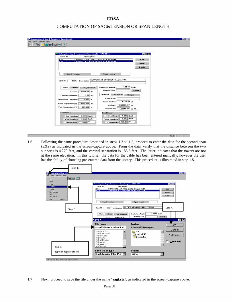
1.6 Following the same procedure described in steps 1.3 to 1.5, proceed to enter the data for the second span (EX2) as indicated in the screen-capture above. From the data, verify that the distance between the two supports is 4,279 feet, and the vertical separation is 185.5 feet. The latter indicates that the towers are not at the same elevation. In this tutorial, the data for the cable has been entered manually, however the user has the ability of choosing pre-entered data from the library. This procedure is illustrated in step 1.5.
1.7 Next, proceed to save the file under the name "sagt.stc", as indicated in the screen-capture above.
Step 1.
Select "File".
Step 2.
Step 3.
Type an appropriate file name. In this case use
Step 4.

EDSA
COMPUTATION OF SAG&TENSION OR SPAN LENGTH
Page 32
1.8 To review the results of the analysis for a specific Span ID, proceed as indicated in the screen-capture above. In this case Span EX1 has been selected.
1.9 The above screen-capture, shows the results for the two environmental conditions specified for Span EX1. To view the results for Span EX2, repeat step 1.8 and 1.9 while selecting EX2. To return, proceed as indicated above.
Step 1.
Step 2.
Calculation results.
To return, select "Close".
EDSA
COMPUTATION OF SAG&TENSION OR SPAN LENGTH
Page 33
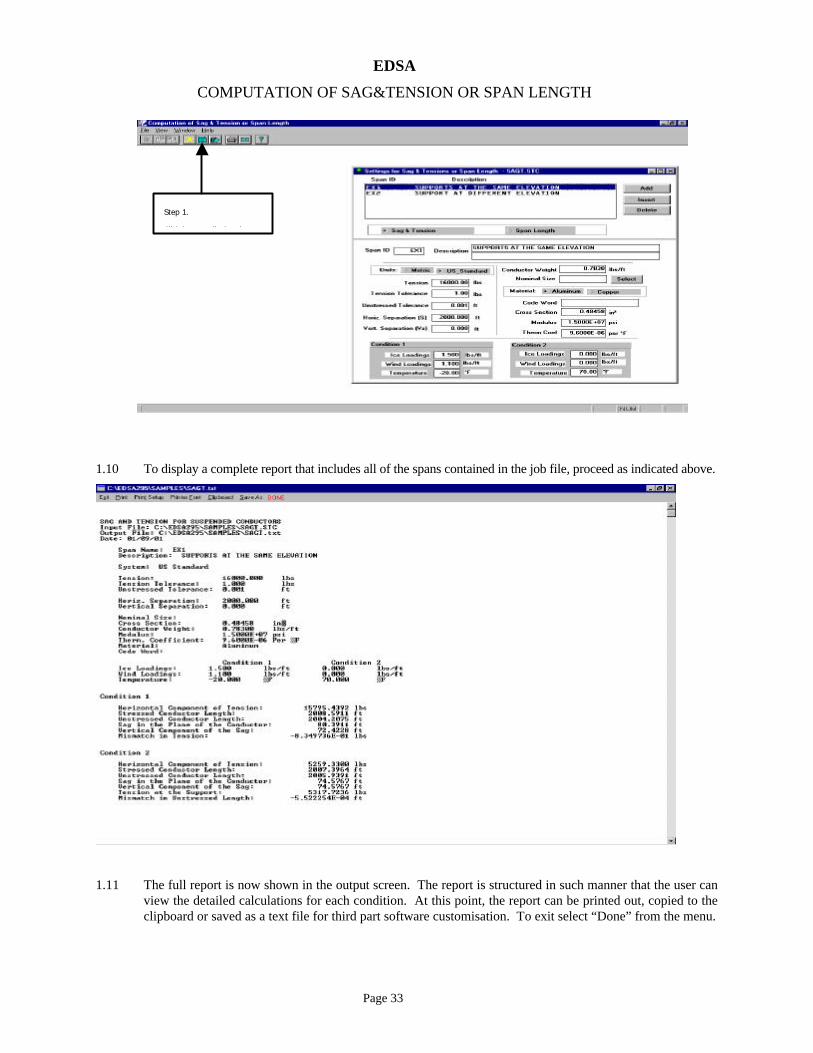
1.10 To display a complete report that includes all of the spans contained in the job file, proceed as indicated above.
1.11 The full report is now shown in the output screen. The report is structured in such manner that the user can view the detailed calculations for each condition. At this point, the report can be printed out, copied to the clipboard or saved as a text file for third part software customisation. To exit select “Done” from the menu.
Step 1.
Click here to display the

EDSA
COMPUTATION OF SAG&TENSION OR SPAN LENGTH
Page 34
1.12 The program offers another pre-formatted report that can be invoked as indicated in the screen-capture above.
1.13 The above screen capture shows a double-page display of the fully formatted report.
Step 1.
Click here to display additional
Single page display
Double page display

EDSA
COMPUTATION OF SAG&TENSION OR SPAN LENGTH
Page 35
2.0 Span Calculations
2.1 To begin, proceed to invoke the "Transmission Line Sag and Tension" program, as indicated in the screen-capture shown above.
2.2 Once the program's main menu appears, proceed to create a new job file, as indicated in the screen-capture above.
Step 1
Step 2 Select "Miscellaneous Analysis".
Step 3
Select "Transmission Line
Step 1.
Select "File".
Step 2.
Select "New".

EDSA
COMPUTATION OF SAG&TENSION OR SPAN LENGTH
Page 36
2.3 Proceed to label the first span under study, as indicated in the screen-capture above.
2.4 Next, proceed to enter the information that describes the various parameters required to calculate the span length and elevation of the mechanical supports. Use the data shown in the screen-capture shown above. From the data, (which corresponds to Span EX1) verify that the vertical separation between the supports is 0 feet. This indicates that the towers are at the same elevation.
Step 3.
Type the "Span ID"
Step 1.
Step 4.
Type a suitable
Step 5.
Select "Add"
Step 6. Verify that the first span has been added
Step 2.
Step 1. Ensure that "Span Length" has been selected for this study.
Step 2.
Fill out this section with the physical data required
Step 3.
Fill out this section with cable and environmental
Step 4.
Specify the relative position of the lowest point
Step 5.
Specify the tolerance factor for the calculation here.

EDSA
COMPUTATION OF SAG&TENSION OR SPAN LENGTH
Page 37
2.5 Following the same procedure described in steps 2.3 to 2.4, proceed to enter the data for the second span as indicated in the screen-capture above. From the data, (which now corresponds to EX2) verify that the vertical separation between the two supports is 185.5 feet. This indicates that the towers are not at the same elevation.
2.6 Next, proceed to save the file under the name "spant.stc", as indicated in the screen-capture above.
Step 1. Select "File".
Step 2. Select "Save As". Step 4.
Step 3. Type an appropriate file name. In this case use "spant.stc".

EDSA
COMPUTATION OF SAG&TENSION OR SPAN LENGTH
Page 38
2.7 To review the results of the analysis for a specific Span ID, proceed as indicated in the screen-capture above. In this case Span EX2 has been selected.
2.8 The above screen-capture, shows the results for the conditions specified for Span EX2. To view the results for Span EX1, repeat step 2.7 and 2.8 while selecting EX1. To return, proceed as indicated above.
Step 1.
Step 2.
Click here.
Calculation results.
To return, select "Close".

EDSA
COMPUTATION OF SAG&TENSION OR SPAN LENGTH
Page 39
2.9 To display a complete report that includes all of the spans contained in the job file, proceed as indicated above.
2.10 The full report is now shown in the output screen. The report is structured in such manner that the user can view the detailed calculations for each condition. At this point, the report can be printed out, copied to the clipboard or saved as a text file for third part software customisation. To exit select “Done” from the menu.
Step 1. Click here to display the full report.

EDSA
COMPUTATION OF SAG&TENSION OR SPAN LENGTH
Page 40
2.11 The program offers another pre-formatted report that can be invoked as indicated in the above screen-capture.
2.12 The above screen capture shows a double-page display of the fully formatted report.
Step 1. Click here to display additional reporting
Single page display command.
Double page display


