Embed Size (px)
Citation preview

samos ® PRO samos ® PLAN 6 Software
Manual Doc. no. BA000968
Last Update: 05/2018 [8960]

Info
Wieland Electric GmbH | BA000968 | 05/2018 [8960] 2
Info 810920587
Copyright
This document is copyright-protected. The rights derived from this copyright are reserved for Wieland Electric. Reproduction of this document or parts of this document is only permissible within the limits of the statutory provision of the Copyright Act. Any modification or abridg-ment of the document is prohibited without the express written agreement of Wieland Electric.
samos is a registered trademark of WIELAND Electric GmbH
Allen-Bradley, CompactBlock Guard I/O, CompactLogix, ControlFLASH, ControlLogix, DH+, FactoryTalk, FLEX, GuardLogix, Kinetix, Logix5000, MicroLogix, PanelBuilder, PanelView, PhaseManager, PLC-2, PLC-3, PLC-5, POINT I/O, POINT Guard I/O, Rockwell Automation, Rockwell Software, RSBizWare, RSFieldbus, RSLinx, RSLogix 5000, RSNetWorx, RSView, SLC, SoftLogix, Stratix, Stratix 2000, Stratix 5700, Stratix 6000, Stratix 8000, Stratix 8300, Studio 5000, Studio 5000 Logix Designer, SynchLink, and Ultra are registered trademarks of Rockwell Automation, Inc.
ControlNet, DeviceNet, and EtherNet/IP are registered trademarks of ODVA, Inc.
TwinCAT is a registered trademark of Beckhoff Automation GmbH.
EtherCAT is a registered trademark and a patented technology licensed by Beckhoff Automa-tion GmbH.
Microsoft, Windows 98, Windows NT, Windows 2000, Windows XP, Windows 7, Windows 8, Windows 8.1, Windows 10 and .NET Framework are registered trademarks of the Microsoft Corporation.
Any other product or trade names listed in this manual are the trademarks or registered trade-marks of the respective owners.
Subject to change.
Subject to technical changes for reasons of continued development.
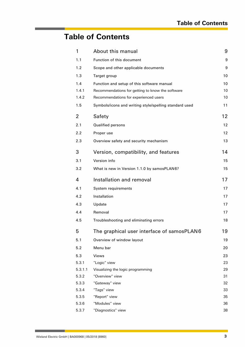
Table of Contents
Wieland Electric GmbH | BA000968 | 05/2018 [8960] 3
Table of Contents
1 About this manual 9
1.1 Function of this document 9
1.2 Scope and other applicable documents 9
1.3 Target group 10
1.4 Function and setup of this software manual 10
1.4.1 Recommendations for getting to know the software 10
1.4.2 Recommendations for experienced users 10
1.5 Symbols/icons and writing style/spelling standard used 11
2 Safety 12
2.1 Qualified persons 12
2.2 Proper use 12
2.3 Overview safety and security mechanism 13
3 Version, compatibility, and features 14
3.1 Version info 15
3.2 What is new in Version 1.1.0 by samosPLAN 6? 15
4 Installation and removal 17
4.1 System requirements 17
4.2 Installation 17
4.3 Update 17
4.4 Removal 17
4.5 Troubleshooting and eliminating errors 18
5 The graphical user interface of samosPLAN 6 19
5.1 Overview of window layout 19
5.2 Menu bar 20
5.3 Views 23
5.3.1 "Logic" view 23
5.3.1.1 Visualizing the logic programming 29
5.3.2 "Overview" view 31
5.3.3 "Gateway" view 32
5.3.4 "Tags" view 33
5.3.5 "Report" view 35
5.3.6 "Modules” view 36
5.3.7 "Diagnostics" view 38
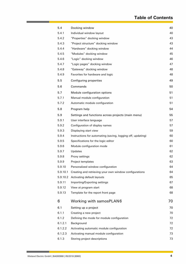
Table of Contents
Wieland Electric GmbH | BA000968 | 05/2018 [8960] 4
5.4 Docking window 40
5.4.1 Individual window layout 40
5.4.2 "Properties” docking window 43
5.4.3 "Project structure” docking window 43
5.4.4 "Hardware” docking window 44
5.4.5 "Modules” docking window 45
5.4.6 "Logic” docking window 46
5.4.7 "Logic pages” docking window 47
5.4.8 "Gateway” docking window 48
5.4.9 Favorites for hardware and logic 48
5.5 Configuring properties 49
5.6 Commands 50
5.7 Module configuration options 51
5.7.1 Manual module configuration 51
5.7.2 Automatic module configuration 51
5.8 Program help 54
5.9 Settings and functions across projects (main menu) 55
5.9.1 User interface language 57
5.9.2 Configuration of display names 57
5.9.3 Displaying start view 59
5.9.4 Instructions for automating (saving, logging off, updating) 60
5.9.5 Specifications for the logic editor 60
5.9.6 Module configuration mode 61
5.9.7 Updates 62
5.9.8 Proxy settings 62
5.9.9 Project templates 63
5.9.10 Personalized window configuration 64
5.9.10.1 Creating and retrieving your own window configurations 64
5.9.10.2 Activating default layouts 65
5.9.11 Importing/Exporting settings 67
5.9.12 View at program start 68
5.9.13 Template for the report front page 68
6 Working with samosPLAN 6 70
6.1 Setting up a project 70
6.1.1 Creating a new project 70
6.1.2 Defining the mode for module configuration 72
6.1.2.1 Background 72
6.1.2.2 Activating automatic module configuration 72
6.1.2.3 Activating manual module configuration 73
6.1.3 Storing project descriptions 73
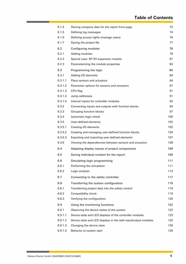
Table of Contents
Wieland Electric GmbH | BA000968 | 05/2018 [8960] 5
6.1.4 Storing company data for the report front page 73
6.1.5 Defining log messages 74
6.1.6 Defining access rights (manage users) 76
6.1.7 Saving the project file 77
6.2 Configuring modules 78
6.2.1 Adding modules 78
6.2.2 Special case: SP-XX expansion module 81
6.2.3 Parameterizing the module properties 83
6.3 Programming the logic 84
6.3.1 Adding I/O elements 84
6.3.1.1 Place sensors and actuators 84
6.3.1.2 Parameter options for sensors and actuators 87
6.3.1.3 CPU flag 91
6.3.1.4 Jump addresses 91
6.3.1.5 Internal inputs for controller modules 92
6.3.2 Connecting inputs and outputs with function blocks 94
6.3.3 Grouping function blocks 97
6.3.4 Automatic logic check 100
6.3.5 User-defined elements 102
6.3.5.1 Creating I/O elements 102
6.3.5.2 Creating and managing user-defined function blocks 104
6.3.5.3 Exporting and importing user-defined elements 107
6.3.6 Viewing the dependencies between sensors and actuators 108
6.4 Adapting display names of project components 109
6.5 Saving individual content for the report 109
6.6 Simulating logic programming 111
6.6.1 Performing the simulation 111
6.6.2 Logic analyzer 113
6.7 Connecting to the safety controller 117
6.8 Transferring the system configuration 119
6.8.1 Transferring project data into the safety control 119
6.8.2 Compatibility check 119
6.8.3 Verifying the configuration 120
6.9 Using the monitoring functions 122
6.9.1 Observing the device states of the system 122
6.9.1.1 Device state and LED displays of the controller modules 123
6.9.1.2 Device state and LED displays in the safe input/output modules 125
6.9.1.3 Changing the device state 126
6.9.1.4 Behavior at system start 126
Table of Contents
Wieland Electric GmbH | BA000968 | 05/2018 [8960] 6
6.9.2 Forcing inputs (Force mode) 127
6.9.3 Synchronize time for diagnostic purposes 131
7 Referencing the function blocks 133
7.1 General safety information regarding logic programming 133
7.2 Function block overview 135
7.3 Function block properties 137
7.4 Input and output signal connections of function blocks 138
7.4.1 Function block input connections 138
7.4.2 Inverting inputs or outputs 138
7.4.3 Output connections of function blocks 140
7.5 Parameterization of function blocks 141
7.5.1 Time values and logic execution time 141
7.5.2 Error outputs 141
7.6 Logical function blocks 142
7.6.1 NOT 142
7.6.2 AND 142
7.6.3 OR 144
7.6.4 XOR (exclusive OR) 145
7.6.5 T flip-flop 146
7.6.6 RS flip-flop 147
7.6.7 JK flip-flop 148
7.6.8 Clock generator 150
7.6.9 Event counter (upward, downward, up- and downward) 152
7.6.10 Fast shut-off and fast shut-off with bypass 155
7.6.11 Edge detection 161
7.6.12 Binary encoder 162
7.6.13 Binary decoder 165
7.6.14 Log generator 169
7.6.15 Residual memory 172
7.7 Application-specific function blocks 173
7.7.1 Reset 173
7.7.2 Restart 175
7.7.3 Switch-off delay timer 176
7.7.4 Adjustable switching-off delay 178
7.7.5 Switch-on delay timer 179
7.7.6 Adjustable switching-on delay 180
7.7.7 EDM (Contact monitor) 181
7.7.8 Valve monitoring 182
Table of Contents
Wieland Electric GmbH | BA000968 | 05/2018 [8960] 7
7.7.9 Operation mode selection switch 185
7.7.10 Ramp down detection 187
7.8 Function blocks for two-channel evaluation 192
7.8.1 Emergency stop 193
7.8.2 Solenoid switch 194
7.8.3 Light curtain evaluation 195
7.8.4 Switch evaluation 196
7.8.5 Two-hand control, type IIIA 198
7.8.6 Two-hand control, type IIIC 198
7.8.7 Multi-operator start 200
7.9 Function blocks for parallel muting, sequential muting, and cross muting
202
7.9.1 Overview and general description 202
7.9.2 Parameters of the function blocks 205
7.9.2.1 Directional detection 206
7.9.2.2 Condition for muting start 206
7.9.2.3 Condition for muting end 206
7.9.2.4 Total muting time 206
7.9.2.5 Additional muting time after the contactless safety device is free 207
7.9.2.6 Simultaneity monitoring time 207
7.9.2.7 Suppressing sensor signal gaps 207
7.9.2.8 Sequence monitoring 207
7.9.2.9 C1 input 208
7.9.2.10 Override input 208
7.9.2.11 Belt signal 210
7.9.2.12 Min. override pulse time 210
7.9.2.13 Muting status output 210
7.9.2.14 Muting lamp output 211
7.9.2.15 Muting error output 211
7.9.2.16 Release output 211
7.9.3 Information regarding cabling 212
7.9.4 State transition from stop to run 213
7.9.5 Error states and information regarding reset 213
7.9.6 Parallel muting 214
7.9.7 Sequential muting 216
7.9.8 Cross-muting (one-sided) 218
7.9.9 Cross-muting (two-sided) 220
Table of Contents
Wieland Electric GmbH | BA000968 | 05/2018 [8960] 8
7.10 Function blocks for presses 222
7.10.1 Function blocks for press contact monitoring 222
7.10.1.1 Overview and general description 222
7.10.1.2 Eccentric press contact monitor 223
7.10.1.3 Universal press contact monitor 230
7.10.2 Function blocks for press cycle control 241
7.10.2.1 Press setup 241
7.10.2.2 Press single stroke 246
7.10.2.3 Press automatic mode 254
7.10.2.4 Cyclic operation 260
7.11 Function blocks for motion monitoring 272
7.11.1 Standstill monitor 272
7.11.1.1 Abbreviations and definitions for standstill monitors 272
7.11.1.2 Function block diagram 272
7.11.1.3 General description 274
7.11.1.4 Operating modes 275
7.11.1.5 Description of the inputs 276
7.11.1.6 Description of the outputs 277
7.11.1.7 Standstill frequency and hysteresis 278
7.11.1.8 Restart (restart block) 279
7.11.1.9 Description of Reset 279
7.11.1.10 Description of Bypass/Mute (bypass mode) 281
7.11.1.11 Errors and warnings 283
8 Technical commissioning 286
8.1 Wiring and supply voltage 286
8.2 Transferring the configuration 286
8.3 Technical check and commissioning 287
9 Troubleshooting 288
10 Appendix 289
10.1 Complete list of error messages 289
About this manual
Wieland Electric GmbH | BA000968 | 05/2018 [8960] 9
About this manual 839293067
Please read this section carefully before you work with this software manual and the sa-mosPRO system.
Function of this document 839335179
There are three manuals for the samosPRO system with clearly delineated areas of application as well as installation instructions and brief instructions for each module.
• This software manual describes the programming of the system in which modules from the samosPRO COMPACT device family are installed.
The software-supported configuration and parameter setting of these devices is described in this manual. In addition, the software manual contains a description of the important di-agnostic functions for operation and detailed information for identifying and eliminating er-rors. Use the software manual mainly for configuration, commissioning and operation.
• The Hardware manual describes all of the modules and their functions in detail. Use the hardware manual mainly for designing devices.
• The gateway manual describes in-detail the samosPRO gateways and their functions.
• Each module contains the installation instructions/brief instructions. These instructions provide information on the fundamental technical specifications of the modules and con-tain simple installation instructions. Use the installation instructions/brief instructions when installing the samosPRO safety control.
This manual contains original operating instructions in accordance with the Machinery Di-rective.
Scope and other applicable documents 839337099
This software manual is valid for the samosPLAN 6 software, starting with version 1.0.x and the controller module SP-COPx starting with version A-01.
This manual contains original operating instructions in accordance with the Machinery Di-rective.
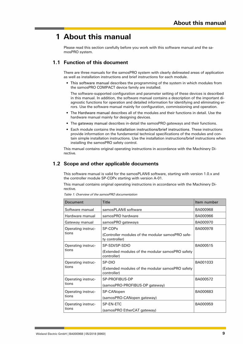
Table 1: Overview of the samosPRO documentation
Document Title Item number
Software manual samosPLAN 6 software BA000968
Hardware manual samosPRO hardware BA000966
Gateway manual samosPRO gateways BA000970
Operating instruc-tions
SP-COPx
(Controller modules of the modular samosPRO safe-ty controller)
BA000978
Operating instruc-tions
SP-SDI/SP-SDIO
(Extended modules of the modular samosPRO safety controller)
BA000515
Operating instruc-tions
SP-DIO
(Extended modules of the modular samosPRO safety controller)
BA001033
Operating instruc-tions
SP-PROFIBUS-DP
(samosPRO-PROFIBUS-DP gateway)
BA000572
Operating instruc-tions
SP-CANopen
(samosPRO-CANopen gateway)
BA000683
Operating instruc-tions
SP-EN-ETC
(samosPRO EtherCAT gateway)
BA000959
1
1.1
1.2
About this manual
Wieland Electric GmbH | BA000968 | 05/2018 [8960] 10
Target group 839359243
This software manual is intended for users of the samosPLAN 6 software and developers and operators of systems in which a samosPRO module safety control is integrated. It is also aimed at persons commissioning such a system for the first time or maintaining such a system.
This software manual does not provide instructions for operating the machine or system in which a samosPRO safety control is integrated. Information on this is provided by the operat-ing instructions of the corresponding machine or system.
Function and setup of this software manual 839364747
This software manual guides technical personnel of the machine manufacturer or machine op-erator in the software configuration, operation, and diagnostics of a samosPRO system with the samosPLAN 6 software. It is only valid together with the Hardware Manual.
The basic safety information can be found here:
• Section: Safety [ch. 2, p. 12]
• Please ensure that you read this information.
NOTICE Also consult our website on the Internet at the following link: http://www.wielandinc.com/ There you will find the following files available for download: • samosPLAN 6 software • Hardware and software manuals. • EDS and GSD files
Recommendations for getting to know the software 839399819
We recommend the following procedure for users wishing to familiarize themselves for the first time with the samosPLAN 6 software:
• Please read the section titled The graphical user interface of samosPLAN 6 [ch. 5, p. 19] in order to familiarize yourself with the layout of the software.
• Along with your first samosPLAN 6 projects, follow the guidelines under Working with sa-mosPLAN 6 [ch. 6, p. 70].
Recommendations for experienced users 839983755
We recommend the following procedure for experienced users who have already worked with the samosPLAN 6 software:
• Please familiarize yourself with the current version of the software (Scope and other appli-cable documents [ch. 1.2, p. 9]).
• The table of contents lists all of the functions provided by the samosPLAN 6 software. Please use the table of contents to find information about the basic functions.
1.3
1.4
1.4.1
1.4.2

About this manual
Wieland Electric GmbH | BA000968 | 05/2018 [8960] 11
Symbols/icons and writing style/spelling standard used 840010507
NOTICE These are notes that provide you with information regarding particularities of a device or a software function.
ATTENTION
Warning! A warning lets you know about specific or potential hazards. It is intended to protect you from accidents and help prevent damage to devices and systems. • Please read and follow the warnings carefully!
Failure to do so may negatively impact the safety functions and cause a hazardous state to occur.
Menus and commands
The names of software menus, submenus, options, and commands, selection fields, and win-dows are written in bold font. Example: Click on Edit in the File menu.
1.5
Safety
Wieland Electric GmbH | BA000968 | 05/2018 [8960] 12
Safety 839347851
This section is intended to support your safety and the safety of the system users. Please read this section carefully before you work with a samosPRO system.
Qualified persons 839350283
A samosPRO system may only be installed, configured, commissioned, and serviced by quali-fied persons.
Qualified persons are those who
• have suitable technical training and
• have been trained by the machine operator in the operation and applicable safety guide-lines and
• have access to the samosPRO system operating instructions and have read them and duly noted their contents.
Proper use 840020491
The samosPLAN 6 software is used to configure a safety control comprising modules in the samosPRO COMPACT device family.
A samosPRO system may only be operated by qualified persons and may only be used on a machine on which the hardware and software have been installed and commissioned for the first time by a qualified person in accordance with the software and hardware manual.
ATTENTION
Any other use or any changes to the software or the devices – including within the scope of installation – shall nullify any sort of warranty claim against Wieland Electric GmbH. • Follow the safety instructions and implement the protective measures described in the
software and hardware manual. • When implementing safety-relevant control logic, ensure that the regulations of national
and international standards are adhered to, particularly the control strategies and measures for reducing risk that are prescribed for your application.
NOTICE Please follow the standards and guidelines which apply in your country when installing and using a samosPRO system.
NOTICE The national and international legal regulations apply to the installation and use of the sa-mosPRO safety control as well as for the commissioning and repeated technical testing, par-ticularly the following: • Machinery Directive 2006/42/EC, • EMC Directive 2014/30/EC, • Work Equipment Directive 2009/104/EC and the supplementary directive 35/63/EC, • Low-Voltage Directive 2014/35/EC, and • The accident prevention regulations and safety rules.
NOTICE The software and hardware manual must be provided to the operator of the machine on which a samosPRO system is being used. The machine operator must be trained by a quali-fied person and required to read the manuals.
2
2.1
2.2
Safety
Wieland Electric GmbH | BA000968 | 05/2018 [8960] 13
Overview safety and security mechanism 862887051
As the software for configuring and programming safety controls, samosPLAN 6 fulfills the per-tinent requirements for safety products (e.g. normative requirements of IEC 61508).
Functional safety
In the area of functional safety (Safety aspect), the following mechanisms apply in sa-mosPLAN 6:
• Automatic review of the logic configuration for connection errors Further information: Automatic logic check [ch. 6.3.4, p. 100]
• Warning in the event of test pulse deactivation Additional information: Parameter options for sensors and actuators [ch. 6.3.1.2, p. 89]
• Blocking of functions if safety-relevant preconditions are not fulfilled Example: Verification is not possible until there are no more connection errors
• Default value ranges for configuration parameters
• Automatic calculation of the required CPU cycle time for the entire project (status bar on right) This means that you always can see the effects that your logic programming are having on the CPU cycle time.
• Checksums (CRC) for central safety-relevant project components:
– CRC for the report
– CRC for user-defined logic components
Access security
With regard to security samosPLAN 6, also provides protection for project data in the following aspects:
• User administration that you can use to scale the access options to project content sys-tematically. Important information in this context:
– When you start working with samosPLAN 6, define which user groups you want to set up with which access rights.
– Change the default password for the previously set up user groups.
Further information: User administration [ch. 6.1.6, p. 76]
• Password protection for user-defined libraries. You can precisely determine who can view or change the modules you have developed yourself.
• Encryption of project files Project files cannot be read or evaluated without the samosPLAN 6 software. Those who do not have the appropriate user rights or password cannot open project files, even using samosPLAN 6.
• Password-protected connection to hardware modules in the samosPRO COMPACT device family, further information: Connecting to the safety controller [ch. 6.7, p. 117]
2.3
Version, compatibility, and features
Wieland Electric GmbH | BA000968 | 05/2018 [8960] 14
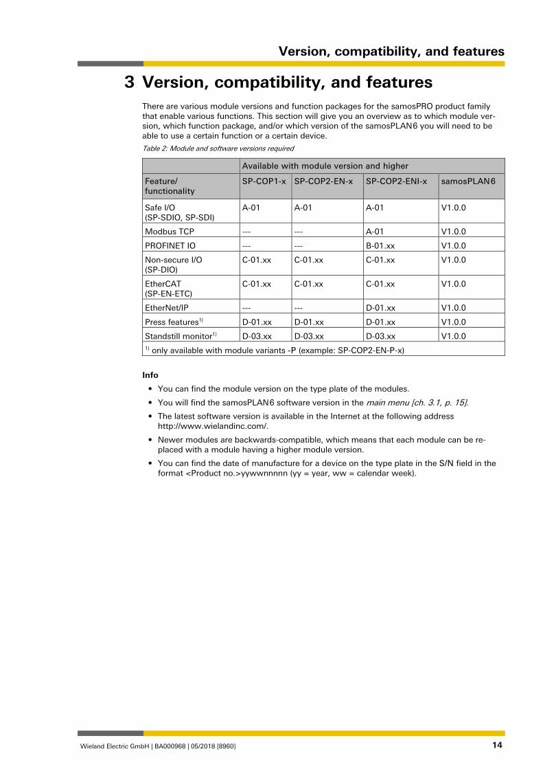
Version, compatibility, and features 840060811
There are various module versions and function packages for the samosPRO product family that enable various functions. This section will give you an overview as to which module ver-sion, which function package, and/or which version of the samosPLAN 6 you will need to be able to use a certain function or a certain device.
Table 2: Module and software versions required
Available with module version and higher
Feature/ functionality
SP-COP1-x SP-COP2-EN-x SP-COP2-ENI-x samosPLAN 6
Safe I/O (SP-SDIO, SP-SDI)
A-01 A-01 A-01 V1.0.0
Modbus TCP --- --- A-01 V1.0.0
PROFINET IO --- --- B-01.xx V1.0.0
Non-secure I/O (SP-DIO)
C-01.xx C-01.xx C-01.xx V1.0.0
EtherCAT (SP-EN-ETC)
C-01.xx C-01.xx C-01.xx V1.0.0
EtherNet/IP --- --- D-01.xx V1.0.0
Press features1) D-01.xx D-01.xx D-01.xx V1.0.0
Standstill monitor1) D-03.xx D-03.xx D-03.xx V1.0.0 1) only available with module variants -P (example: SP-COP2-EN-P-x)
Info
• You can find the module version on the type plate of the modules.
• You will find the samosPLAN 6 software version in the main menu [ch. 3.1, p. 15].
• The latest software version is available in the Internet at the following address http://www.wielandinc.com/.
• Newer modules are backwards-compatible, which means that each module can be re-placed with a module having a higher module version.
• You can find the date of manufacture for a device on the type plate in the S/N field in the format <Product no.>yywwnnnnn (yy = year, ww = calendar week).
3
Version, compatibility, and features
Wieland Electric GmbH | BA000968 | 05/2018 [8960] 15
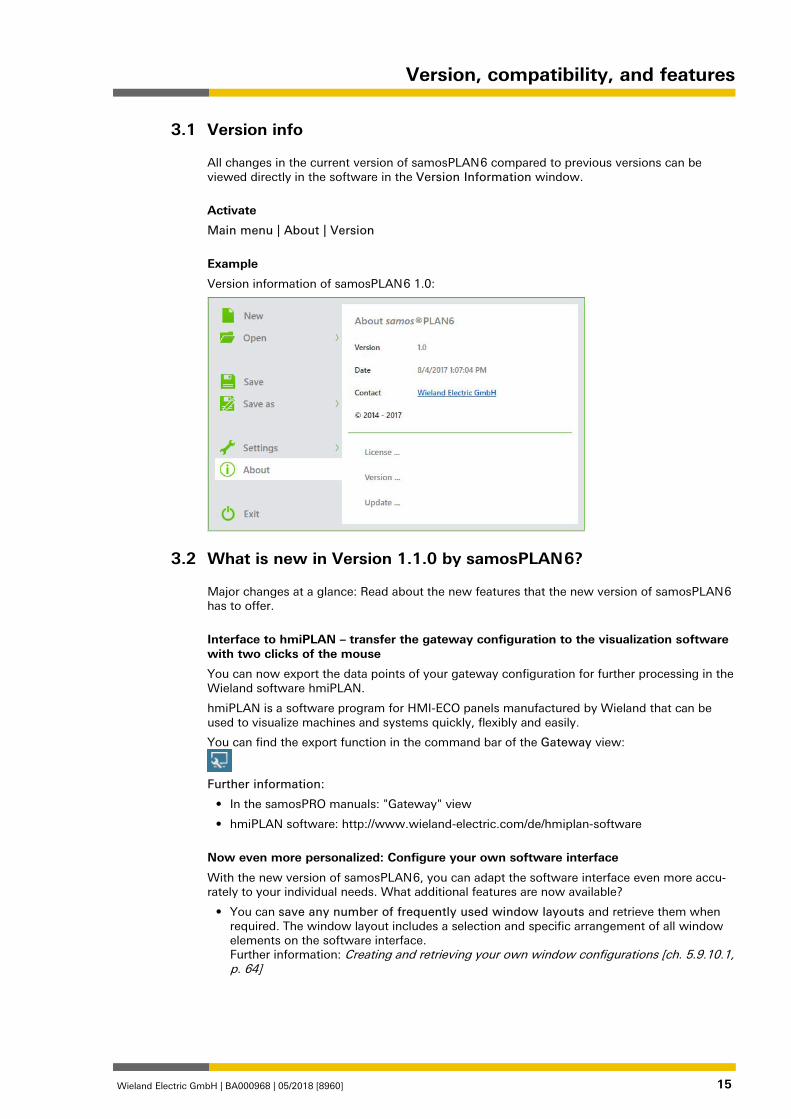
Version info 952680843
All changes in the current version of samosPLAN 6 compared to previous versions can be viewed directly in the software in the Version Information window.
Activate
Main menu | About | Version
Example
Version information of samosPLAN 6 1.0:
What is new in Version 1.1.0 by samosPLAN 6? 1327961739
Major changes at a glance: Read about the new features that the new version of samosPLAN 6 has to offer.
Interface to hmiPLAN – transfer the gateway configuration to the visualization software with two clicks of the mouse
You can now export the data points of your gateway configuration for further processing in the Wieland software hmiPLAN.
hmiPLAN is a software program for HMI-ECO panels manufactured by Wieland that can be used to visualize machines and systems quickly, flexibly and easily.
You can find the export function in the command bar of the Gateway view:
Further information:
• In the samosPRO manuals: "Gateway" view
• hmiPLAN software: http://www.wieland-electric.com/de/hmiplan-software
Now even more personalized: Configure your own software interface
With the new version of samosPLAN 6, you can adapt the software interface even more accu-rately to your individual needs. What additional features are now available?
• You can save any number of frequently used window layouts and retrieve them when required. The window layout includes a selection and specific arrangement of all window elements on the software interface. Further information: Creating and retrieving your own window configurations [ch. 5.9.10.1, p. 64]
3.1
3.2
Version, compatibility, and features
Wieland Electric GmbH | BA000968 | 05/2018 [8960] 16
• The software interface can be changed to the "classic" layout in the style of sa-mosPLAN5+. This is ideal for configuring modules manually. Further information: Activating default layouts [ch. 5.9.10.2, p. 65]
• Which view opens in samosPLAN 6 at program start? You can now define this setting yourself under Layout settings. Further information: View at program start [ch. 5.9.12, p. 68]
Project templates: Start a new project with a predefined configuration
The new version of samosPLAN 6 allows you to work with project templates. A project tem-plate stores all the components of a samosPLAN 6 project including any custom configurations that you have created. You can open project templates at any time and create new projects based on the presets from these templates.
Further information: Project templates [ch. 5.9.9, p. 63]
Different name, more functions: The "Modules” view
In the new version of samosPLAN 6, the Online status view is now called Modules view. It visualizes the current hardware configuration of your safety controller using graphic illustra-tions of the modules used.
Unlike the previous Online status view, you can assign sensors and actuators to inputs and outputs when configuring the module manually. A function that may be familiar to you from samosPLAN5+.
Further information: "Modules” view [ch. 5.3.6, p. 36]
Grouped function blocks: Now with a maximum of 16 inputs and outputs
It is now possible by popular request: You can now assign a maximum of 16 inputs and 16 outputs to grouped function blocks.
Further information: Grouping function blocks [ch. 6.3.3, p. 97]
Editing properties directly in the context menu
In future, you will no longer need to open the Properties docking window to configure proper-ties for project components.
You can now open and edit properties directly in the context menu of the selected project component.
Further information: Configuring properties [ch. 5.5, p. 49]
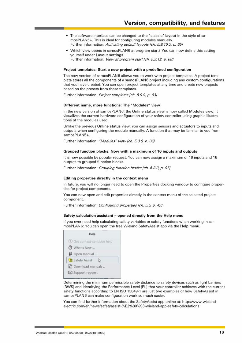
Safety calculation assistant – opened directly from the Help menu
If you ever need help calculating safety variables or safety functions when working in sa-mosPLAN 6: You can open the free Wieland SafetyAssist app via the Help menu.
Determining the minimum permissible safety distance to safety devices such as light barriers (BWS) and identifying the Performance Level (PL) that your controller achieves with the current safety functions according to EN ISO 13849-1 are just two examples of how SafetyAssist in samosPLAN 6 can make configuration work so much easier.
You can find further information about the SafetyAssist app online at: http://www.wieland-electric.com/en/news/safetyassist-%E2%80%93-wieland-app-safety-calculations
Installation and removal
Wieland Electric GmbH | BA000968 | 05/2018 [8960] 17
Installation and removal 840086539
System requirements 840088971
Recommended system configuration:
• Windows Vista, Windows 7, Windows 8.1 or Windows 10
• 2.2 GHz processor
• 3 GB RAM
• 1280 × 800 pixels screen resolution
• 150 MB available hard drive space
The samosPLAN 6 software is a .NET framework application. It requires .NET Framework ver-sion 4.0 or higher (you can find information on the current .NET Framework versions and sup-ported operating systems on the Internet at http://www.microsoft.com/).
Microsoft .NET Framework version 4.0 or higher and any other required components can also be downloaded from http://www.microsoft.com/downloads/.
Installation 840090891
The installation files for samosPLAN 6 can be found on the Internet under http://www.wielandinc.com/. We also provide the installation files on a USB stick in individual cases.
Use one of the following installation files, depending on the computer's operating system:
• 32-bit systems: samosPLAN6_%Version%_Setup.x86.msi
• 64-bit systems: samosPLAN6_%Version%_Setup.x64.msi
Update 840092811
In each case the latest version of the samosPLAN 6 software is available on the Internet at: http://www.wielandinc.com/
New software versions may contain new functions and support new modules of the sa-mosPRO COMPACT device family.
The removal of a previously installed, older software version is not required. However, if an in-stalled, newer version has to be replaced by an older software version, the previously installed version must be removed beforehand.
Removal 840094731
Use the control system's deinstallation function for the deinstallation.
4
4.1
4.2
4.3
4.4
Installation and removal
Wieland Electric GmbH | BA000968 | 05/2018 [8960] 18
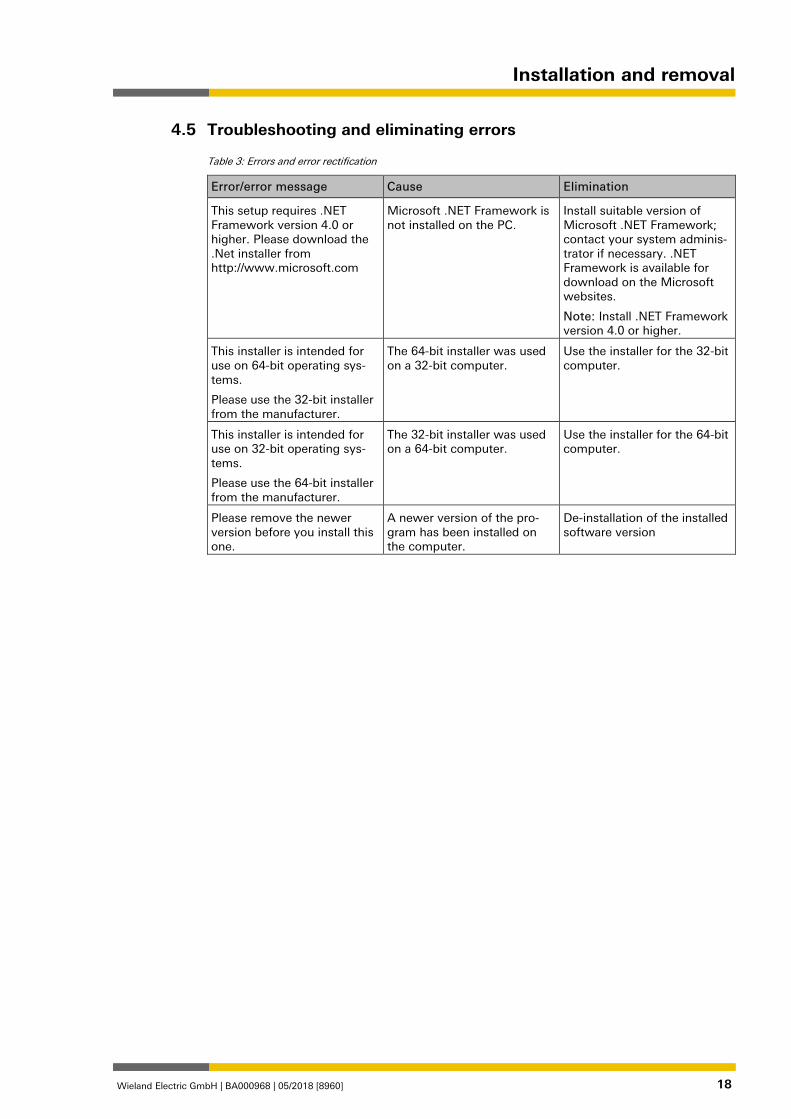
Troubleshooting and eliminating errors 840096651
Table 3: Errors and error rectification
Error/error message Cause Elimination
This setup requires .NET Framework version 4.0 or higher. Please download the .Net installer from http://www.microsoft.com
Microsoft .NET Framework is not installed on the PC.
Install suitable version of Microsoft .NET Framework; contact your system adminis-trator if necessary. .NET Framework is available for download on the Microsoft websites.
Note: Install .NET Framework version 4.0 or higher.
This installer is intended for use on 64-bit operating sys-tems.
Please use the 32-bit installer from the manufacturer.
The 64-bit installer was used on a 32-bit computer.
Use the installer for the 32-bit computer.
This installer is intended for use on 32-bit operating sys-tems.
Please use the 64-bit installer from the manufacturer.
The 32-bit installer was used on a 64-bit computer.
Use the installer for the 64-bit computer.
Please remove the newer version before you install this one.
A newer version of the pro-gram has been installed on the computer.
De-installation of the installed software version
4.5
The graphical user interface of samosPLAN 6
Wieland Electric GmbH | BA000968 | 05/2018 [8960] 19
The graphical user interface of samosPLAN 6 840347019
How is the graphical user interface of samosPLAN 6 constructed? How does the new window layout support you, and which commands and options are available to you?
This chapter offers you a concise overview.
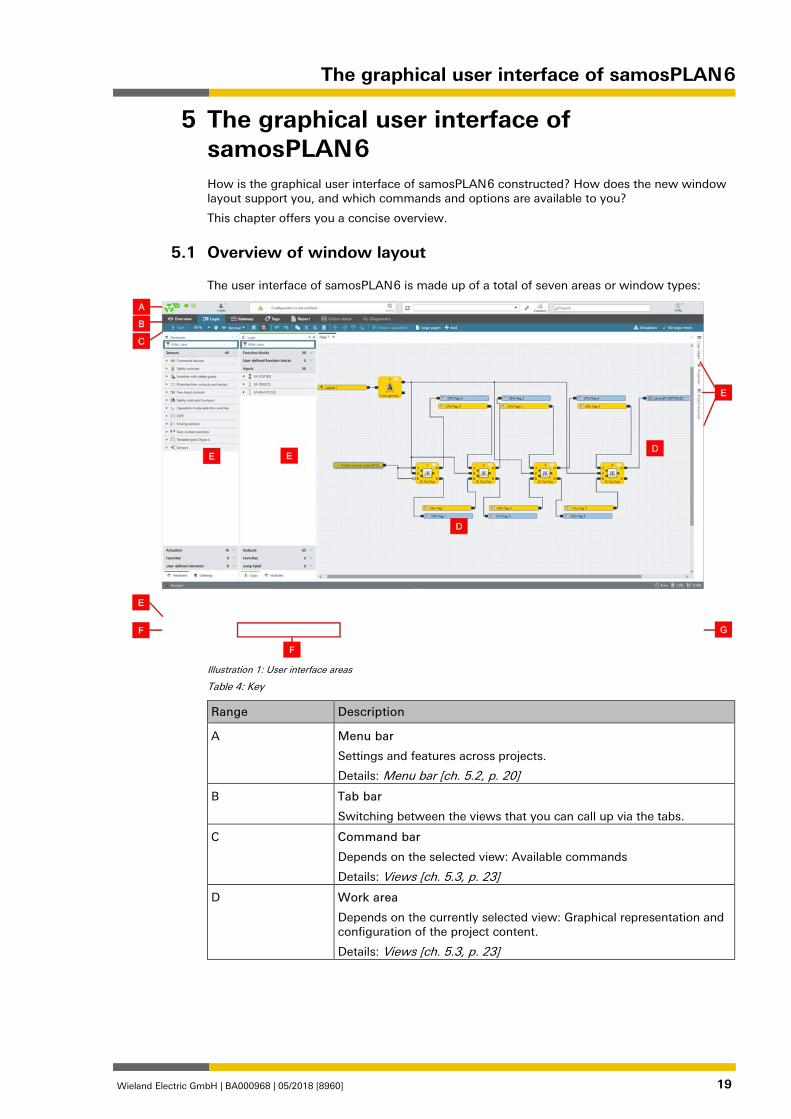
Overview of window layout 862848651
The user interface of samosPLAN 6 is made up of a total of seven areas or window types:
Illustration 1: User interface areas
Table 4: Key
Range Description
A Menu bar
Settings and features across projects.
Details: Menu bar [ch. 5.2, p. 20]
B Tab bar
Switching between the views that you can call up via the tabs.
C Command bar
Depends on the selected view: Available commands
Details: Views [ch. 5.3, p. 23]
D Work area
Depends on the currently selected view: Graphical representation and configuration of the project content.
Details: Views [ch. 5.3, p. 23]
5
5.1
The graphical user interface of samosPLAN 6
Wieland Electric GmbH | BA000968 | 05/2018 [8960] 20
Range Description
E Docking window
Window with configuration or navigation function, which you can arrange either to the right and left of the work area.
Details: Docking window [ch. 5.4, p. 40]
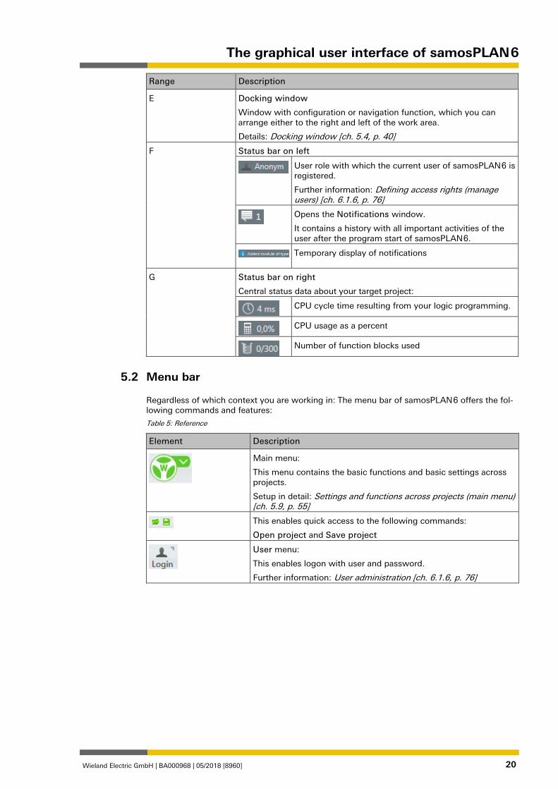
F Status bar on left
User role with which the current user of samosPLAN 6 is registered.
Further information: Defining access rights (manage users) [ch. 6.1.6, p. 76]
Opens the Notifications window.
It contains a history with all important activities of the user after the program start of samosPLAN 6.
Temporary display of notifications
G Status bar on right
Central status data about your target project:
CPU cycle time resulting from your logic programming.
CPU usage as a percent
Number of function blocks used
Menu bar 862865803
Regardless of which context you are working in: The menu bar of samosPLAN 6 offers the fol-lowing commands and features:
Table 5: Reference
Element Description
Main menu:
This menu contains the basic functions and basic settings across projects.
Setup in detail: Settings and functions across projects (main menu) [ch. 5.9, p. 55]
This enables quick access to the following commands:
Open project and Save project
User menu:
This enables logon with user and password.
Further information: User administration [ch. 6.1.6, p. 76]
5.2
The graphical user interface of samosPLAN 6
Wieland Electric GmbH | BA000968 | 05/2018 [8960] 21
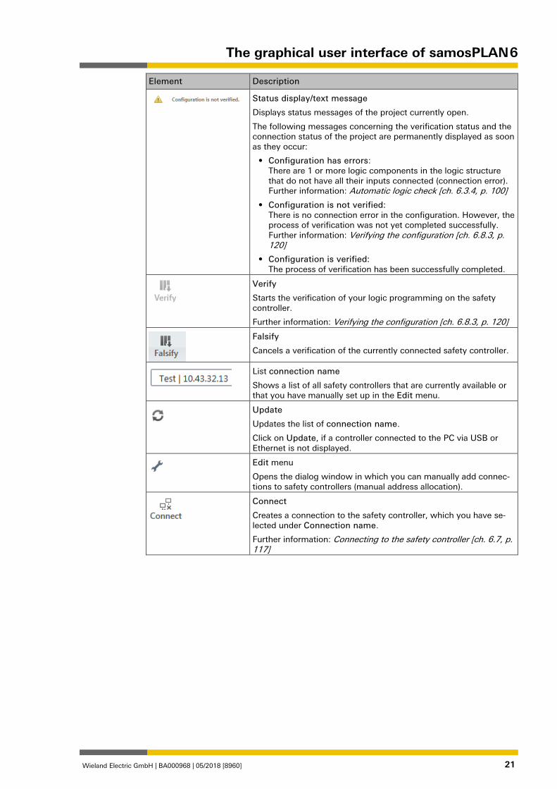
Element Description
Status display/text message
Displays status messages of the project currently open.
The following messages concerning the verification status and the connection status of the project are permanently displayed as soon as they occur:
• Configuration has errors: There are 1 or more logic components in the logic structure that do not have all their inputs connected (connection error). Further information: Automatic logic check [ch. 6.3.4, p. 100]
• Configuration is not verified: There is no connection error in the configuration. However, the process of verification was not yet completed successfully. Further information: Verifying the configuration [ch. 6.8.3, p. 120]
• Configuration is verified: The process of verification has been successfully completed.
Verify
Starts the verification of your logic programming on the safety controller.
Further information: Verifying the configuration [ch. 6.8.3, p. 120]
Falsify
Cancels a verification of the currently connected safety controller.
List connection name
Shows a list of all safety controllers that are currently available or that you have manually set up in the Edit menu.
Update
Updates the list of connection name.
Click on Update, if a controller connected to the PC via USB or Ethernet is not displayed.
Edit menu
Opens the dialog window in which you can manually add connec-tions to safety controllers (manual address allocation).
Connect
Creates a connection to the safety controller, which you have se-lected under Connection name.
Further information: Connecting to the safety controller [ch. 6.7, p. 117]
The graphical user interface of samosPLAN 6
Wieland Electric GmbH | BA000968 | 05/2018 [8960] 22
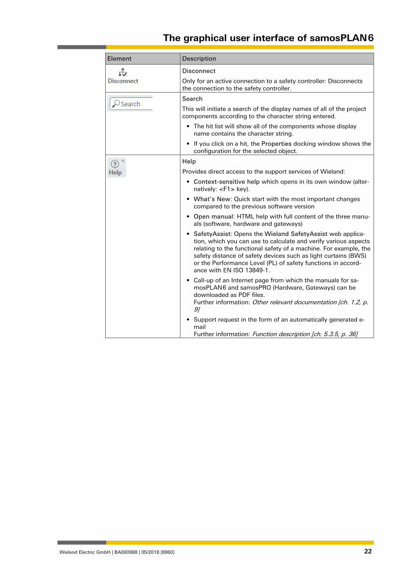
Element Description
Disconnect
Only for an active connection to a safety controller: Disconnects the connection to the safety controller.
Search
This will initiate a search of the display names of all of the project components according to the character string entered.
• The hit list will show all of the components whose display name contains the character string.
• If you click on a hit, the Properties docking window shows the configuration for the selected object.
Help
Provides direct access to the support services of Wieland:
• Context-sensitive help which opens in its own window (alter-natively: <F1> key).
• What’s New: Quick start with the most important changes compared to the previous software version
• Open manual: HTML help with full content of the three manu-als (software, hardware and gateways)
• SafetyAssist: Opens the Wieland SafetyAssist web applica-tion, which you can use to calculate and verify various aspects relating to the functional safety of a machine. For example, the safety distance of safety devices such as light curtains (BWS) or the Performance Level (PL) of safety functions in accord-ance with EN ISO 13849-1.
• Call-up of an Internet page from which the manuals for sa-mosPLAN 6 and samosPRO (Hardware, Gateways) can be downloaded as PDF files. Further information: Other relevant documentation [ch. 1.2, p. 9]
• Support request in the form of an automatically generated e-mail Further information: Function description [ch. 5.3.5, p. 36]
The graphical user interface of samosPLAN 6
Wieland Electric GmbH | BA000968 | 05/2018 [8960] 23
Views 1276693387
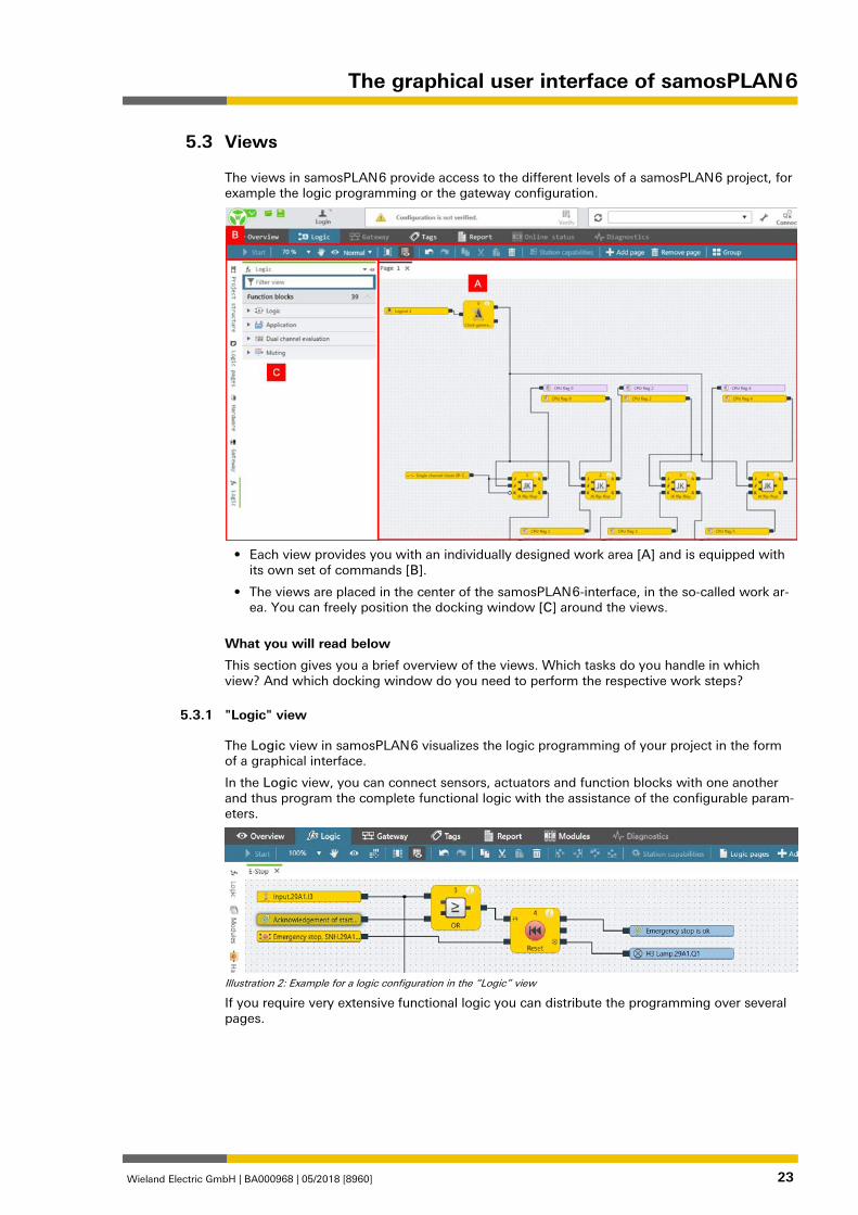
The views in samosPLAN 6 provide access to the different levels of a samosPLAN 6 project, for example the logic programming or the gateway configuration.
• Each view provides you with an individually designed work area [A] and is equipped with
its own set of commands [B].
• The views are placed in the center of the samosPLAN 6-interface, in the so-called work ar-ea. You can freely position the docking window [C] around the views.
What you will read below
This section gives you a brief overview of the views. Which tasks do you handle in which view? And which docking window do you need to perform the respective work steps?
"Logic" view 862943755
The Logic view in samosPLAN 6 visualizes the logic programming of your project in the form of a graphical interface.
In the Logic view, you can connect sensors, actuators and function blocks with one another and thus program the complete functional logic with the assistance of the configurable param-eters.
Illustration 2: Example for a logic configuration in the “Logic” view
If you require very extensive functional logic you can distribute the programming over several pages.
5.3
5.3.1
The graphical user interface of samosPLAN 6
Wieland Electric GmbH | BA000968 | 05/2018 [8960] 24
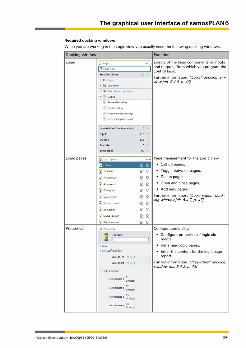
Required docking windows
When you are working in the Logic view you usually need the following docking windows:
Docking window Function
Logic
Library of the logic components or inputs and outputs, from which you program the control logic.
Further information: "Logic” docking win-dow [ch. 5.4.6, p. 46]
Logic pages
Page management for the Logic view
• Call up pages.
• Toggle between pages.
• Delete pages.
• Open and close pages.
• Add new pages.
Further information: "Logic pages” dock-ing window [ch. 5.4.7, p. 47]
Properties
Configuration dialog
• Configure properties of logic ele-ments.
• Renaming logic pages.
• Enter the content for the logic page report.
Further information: "Properties” docking window [ch. 5.4.2, p. 43]
The graphical user interface of samosPLAN 6
Wieland Electric GmbH | BA000968 | 05/2018 [8960] 25
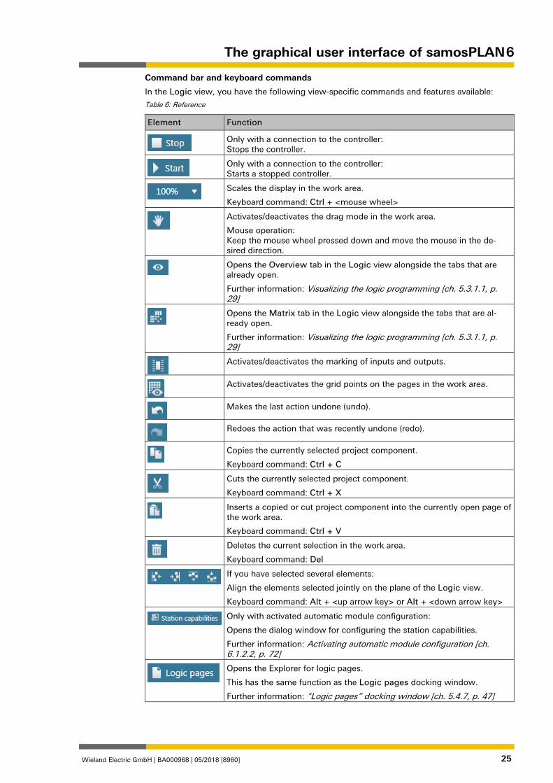
Command bar and keyboard commands
In the Logic view, you have the following view-specific commands and features available:
Table 6: Reference
Element Function
Only with a connection to the controller: Stops the controller.
Only with a connection to the controller: Starts a stopped controller.
Scales the display in the work area.
Keyboard command: Ctrl + <mouse wheel>
Activates/deactivates the drag mode in the work area.
Mouse operation: Keep the mouse wheel pressed down and move the mouse in the de-sired direction.
Opens the Overview tab in the Logic view alongside the tabs that are already open.
Further information: Visualizing the logic programming [ch. 5.3.1.1, p. 29]
Opens the Matrix tab in the Logic view alongside the tabs that are al-ready open.
Further information: Visualizing the logic programming [ch. 5.3.1.1, p. 29]
Activates/deactivates the marking of inputs and outputs.
Activates/deactivates the grid points on the pages in the work area.
Makes the last action undone (undo).
Redoes the action that was recently undone (redo).
Copies the currently selected project component.
Keyboard command: Ctrl + C
Cuts the currently selected project component.
Keyboard command: Ctrl + X
Inserts a copied or cut project component into the currently open page of the work area.
Keyboard command: Ctrl + V
Deletes the current selection in the work area.
Keyboard command: Del
If you have selected several elements:
Align the elements selected jointly on the plane of the Logic view.
Keyboard command: Alt + <up arrow key> or Alt + <down arrow key>
Only with activated automatic module configuration:
Opens the dialog window for configuring the station capabilities.
Further information: Activating automatic module configuration [ch. 6.1.2.2, p. 72]
Opens the Explorer for logic pages.
This has the same function as the Logic pages docking window.
Further information: "Logic pages” docking window [ch. 5.4.7, p. 47]
The graphical user interface of samosPLAN 6
Wieland Electric GmbH | BA000968 | 05/2018 [8960] 26
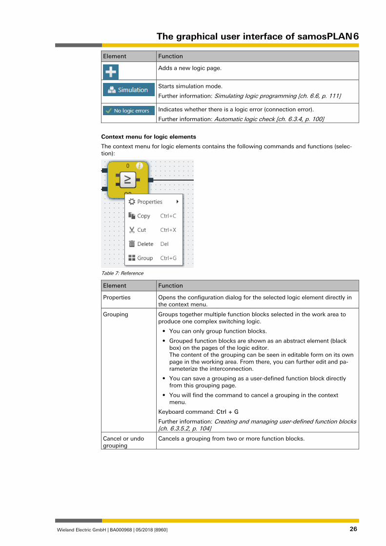
Element Function
Adds a new logic page.
Starts simulation mode.
Further information: Simulating logic programming [ch. 6.6, p. 111]
Indicates whether there is a logic error (connection error).
Further information: Automatic logic check [ch. 6.3.4, p. 100]
Context menu for logic elements
The context menu for logic elements contains the following commands and functions (selec-tion):
Table 7: Reference
Element Function
Properties Opens the configuration dialog for the selected logic element directly in the context menu.
Grouping Groups together multiple function blocks selected in the work area to produce one complex switching logic.
• You can only group function blocks.
• Grouped function blocks are shown as an abstract element (black box) on the pages of the logic editor. The content of the grouping can be seen in editable form on its own page in the working area. From there, you can further edit and pa-rameterize the interconnection.
• You can save a grouping as a user-defined function block directly from this grouping page.
• You will find the command to cancel a grouping in the context menu.
Keyboard command: Ctrl + G
Further information: Creating and managing user-defined function blocks [ch. 6.3.5.2, p. 104]
Cancel or undo grouping
Cancels a grouping from two or more function blocks.
The graphical user interface of samosPLAN 6
Wieland Electric GmbH | BA000968 | 05/2018 [8960] 27
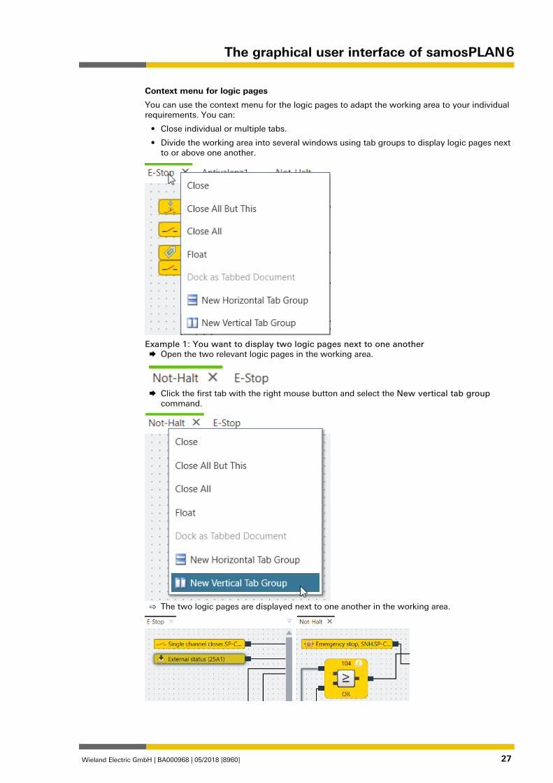
Context menu for logic pages
You can use the context menu for the logic pages to adapt the working area to your individual requirements. You can:
• Close individual or multiple tabs.
• Divide the working area into several windows using tab groups to display logic pages next to or above one another.
Example 1: You want to display two logic pages next to one another Open the two relevant logic pages in the working area.
Click the first tab with the right mouse button and select the New vertical tab group
command.
⇨ The two logic pages are displayed next to one another in the working area.
The graphical user interface of samosPLAN 6
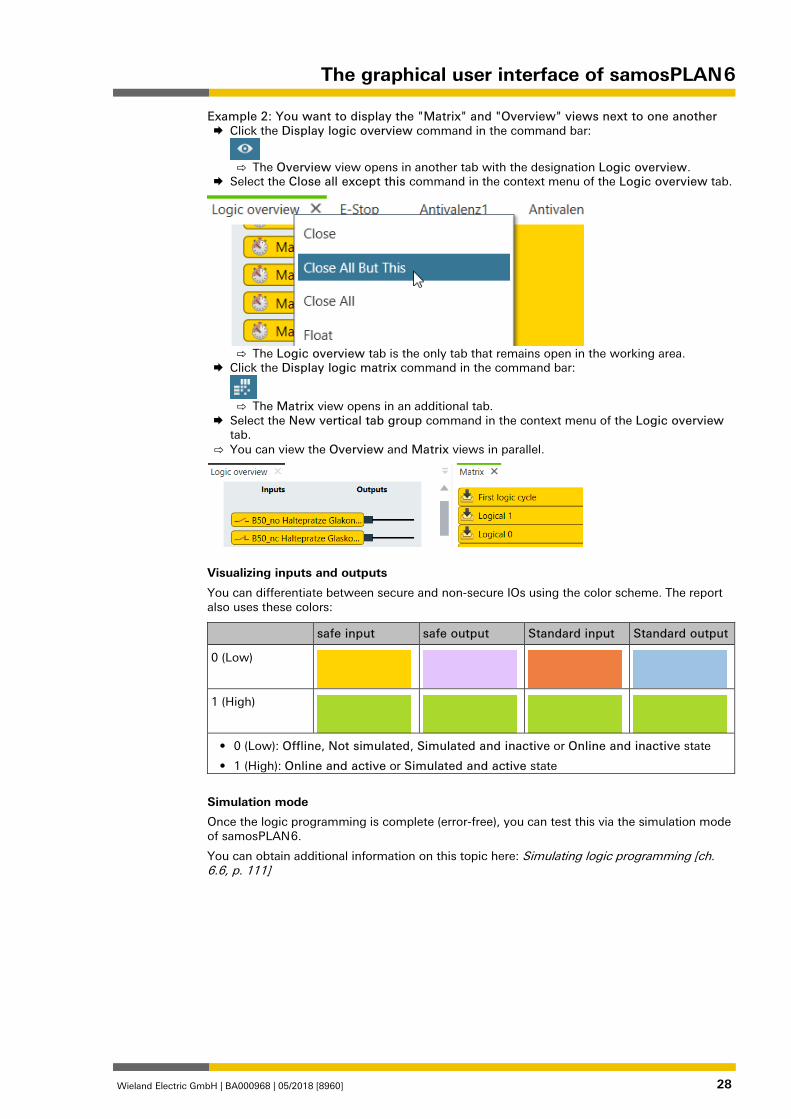
Wieland Electric GmbH | BA000968 | 05/2018 [8960] 28
Example 2: You want to display the "Matrix" and "Overview" views next to one another Click the Display logic overview command in the command bar:
⇨ The Overview view opens in another tab with the designation Logic overview.
Select the Close all except this command in the context menu of the Logic overview tab.
⇨ The Logic overview tab is the only tab that remains open in the working area.
Click the Display logic matrix command in the command bar:
⇨ The Matrix view opens in an additional tab.
Select the New vertical tab group command in the context menu of the Logic overview tab.
⇨ You can view the Overview and Matrix views in parallel.
Visualizing inputs and outputs
You can differentiate between secure and non-secure IOs using the color scheme. The report also uses these colors:
safe input safe output Standard input Standard output
0 (Low)
1 (High)
• 0 (Low): Offline, Not simulated, Simulated and inactive or Online and inactive state
• 1 (High): Online and active or Simulated and active state
Simulation mode
Once the logic programming is complete (error-free), you can test this via the simulation mode of samosPLAN 6.
You can obtain additional information on this topic here: Simulating logic programming [ch. 6.6, p. 111]

The graphical user interface of samosPLAN 6
Wieland Electric GmbH | BA000968 | 05/2018 [8960] 29
862970891
Visualizing the logic programming
In order to ensure an optimal overview in extensive projects, you can visualize the logic pro-gramming in samosPLAN 6 in three different ways.
The logic pages and all project components are displayed in the Logic view by default. On the logic pages, you can place and configure the project components or combine them with one another.
You can use two other types of visualization in addition to the analytical visualization on the logic pages. They open as additional tabs in the Logic view when you click the corresponding buttons:
Element Function
Opens the Overview tab.
Opens the Matrix tab.
"Overview” tab
This tab shows all of the inputs and outputs, per page, that you use in logic programming. The logical links (logic components and connections) are shown in abstract as a black box.
Illustration 3: "Overview" view
5.3.1.1
The graphical user interface of samosPLAN 6
Wieland Electric GmbH | BA000968 | 05/2018 [8960] 30
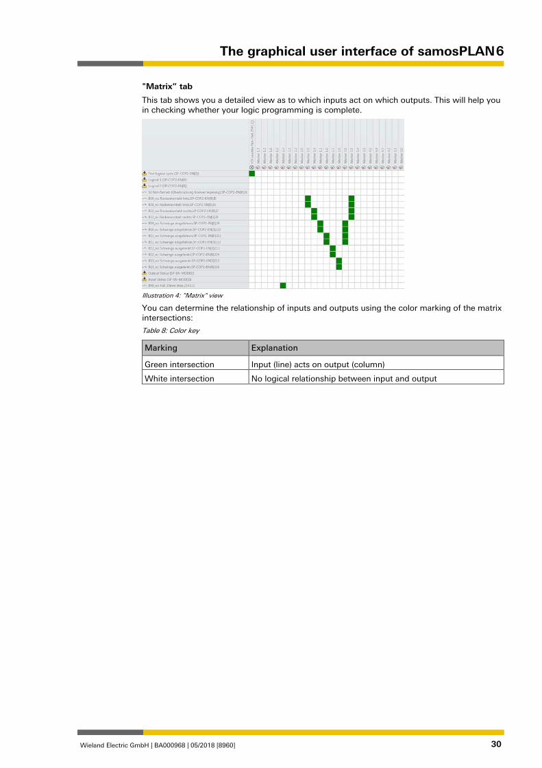
"Matrix” tab
This tab shows you a detailed view as to which inputs act on which outputs. This will help you in checking whether your logic programming is complete.
Illustration 4: "Matrix" view
You can determine the relationship of inputs and outputs using the color marking of the matrix intersections:
Table 8: Color key
Marking Explanation
Green intersection Input (line) acts on output (column)
White intersection No logical relationship between input and output
The graphical user interface of samosPLAN 6
Wieland Electric GmbH | BA000968 | 05/2018 [8960] 31
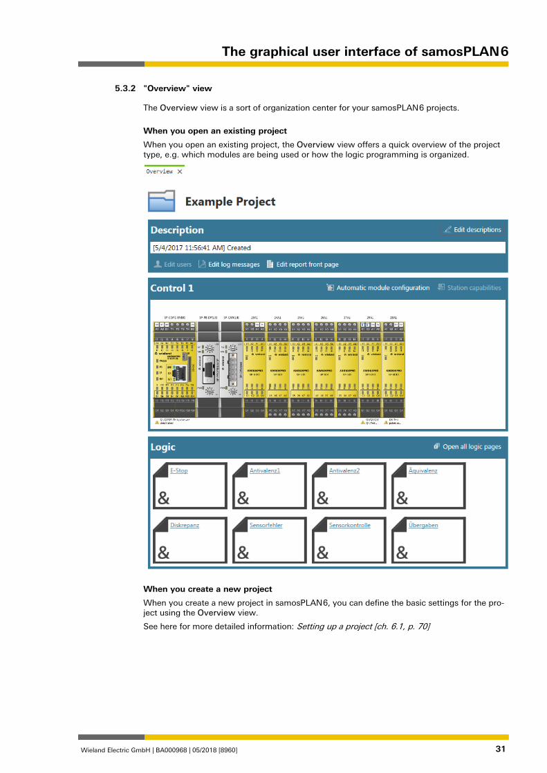
"Overview" view 862906123
The Overview view is a sort of organization center for your samosPLAN 6 projects.
When you open an existing project
When you open an existing project, the Overview view offers a quick overview of the project type, e.g. which modules are being used or how the logic programming is organized.
When you create a new project
When you create a new project in samosPLAN 6, you can define the basic settings for the pro-ject using the Overview view.
See here for more detailed information: Setting up a project [ch. 6.1, p. 70]
5.3.2
The graphical user interface of samosPLAN 6
Wieland Electric GmbH | BA000968 | 05/2018 [8960] 32
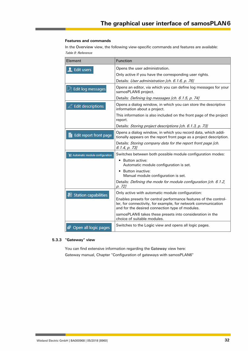
Features and commands
In the Overview view, the following view-specific commands and features are available:
Table 9: Reference
Element Function
Opens the user administration.
Only active if you have the corresponding user rights.
Details: User administration [ch. 6.1.6, p. 76]
Opens an editor, via which you can define log messages for your samosPLAN 6 project.
Details: Defining log messages [ch. 6.1.5, p. 74]
Opens a dialog window, in which you can store the descriptive information about a project.
This information is also included on the front page of the project report.
Details: Storing project descriptions [ch. 6.1.3, p. 73]
Opens a dialog window, in which you record data, which addi-tionally appears on the report front page as a project description.
Details: Storing company data for the report front page [ch. 6.1.4, p. 73]
Switches between both possible module configuration modes:
• Button active: Automatic module configuration is set.
• Button inactive: Manual module configuration is set.
Details: Defining the mode for module configuration [ch. 6.1.2, p. 72]
Only active with automatic module configuration:
Enables presets for central performance features of the control-ler, for connectivity, for example, for network communication and for the desired connection type of modules.
samosPLAN 6 takes these presets into consideration in the choice of suitable modules.
Switches to the Logic view and opens all logic pages.
"Gateway" view 862977291
You can find extensive information regarding the Gateway view here:
Gateway manual, Chapter "Configuration of gateways with samosPLAN6"
5.3.3
The graphical user interface of samosPLAN 6
Wieland Electric GmbH | BA000968 | 05/2018 [8960] 33
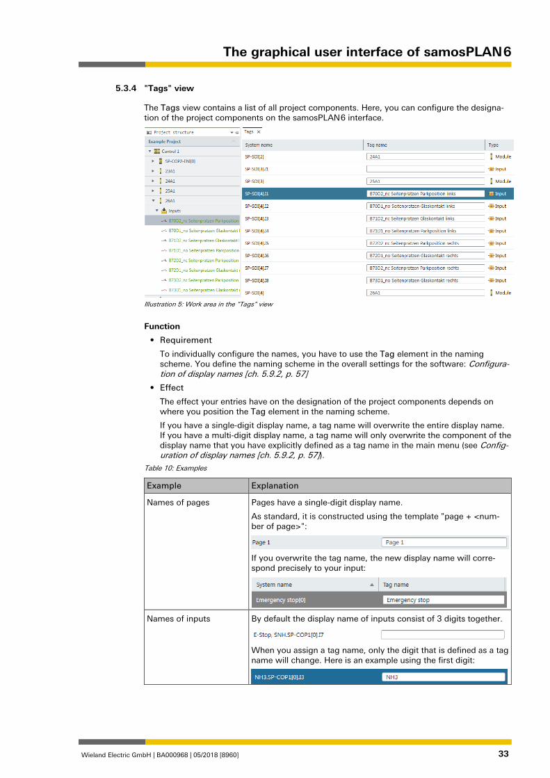
"Tags" view 862980363
The Tags view contains a list of all project components. Here, you can configure the designa-tion of the project components on the samosPLAN 6 interface.
Illustration 5: Work area in the "Tags" view
Function
• Requirement
To individually configure the names, you have to use the Tag element in the naming scheme. You define the naming scheme in the overall settings for the software: Configura-tion of display names [ch. 5.9.2, p. 57]
• Effect
The effect your entries have on the designation of the project components depends on where you position the Tag element in the naming scheme.
If you have a single-digit display name, a tag name will overwrite the entire display name. If you have a multi-digit display name, a tag name will only overwrite the component of the display name that you have explicitly defined as a tag name in the main menu (see Config-uration of display names [ch. 5.9.2, p. 57]).
Table 10: Examples
Example Explanation
Names of pages Pages have a single-digit display name.
As standard, it is constructed using the template "page + <num-ber of page>":
If you overwrite the tag name, the new display name will corre-spond precisely to your input:
Names of inputs By default the display name of inputs consist of 3 digits together.
When you assign a tag name, only the digit that is defined as a tag name will change. Here is an example using the first digit:
5.3.4
The graphical user interface of samosPLAN 6
Wieland Electric GmbH | BA000968 | 05/2018 [8960] 34
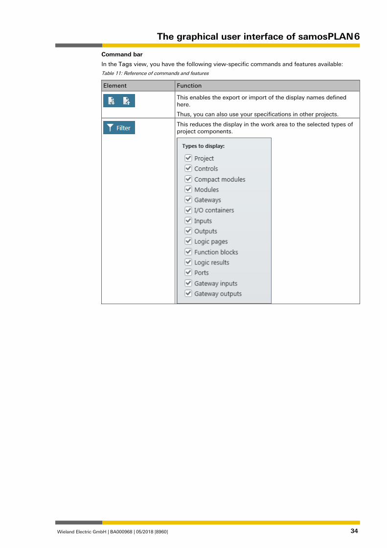
Command bar
In the Tags view, you have the following view-specific commands and features available:
Table 11: Reference of commands and features
Element Function
This enables the export or import of the display names defined here.
Thus, you can also use your specifications in other projects.
This reduces the display in the work area to the selected types of project components.
The graphical user interface of samosPLAN 6
Wieland Electric GmbH | BA000968 | 05/2018 [8960] 35
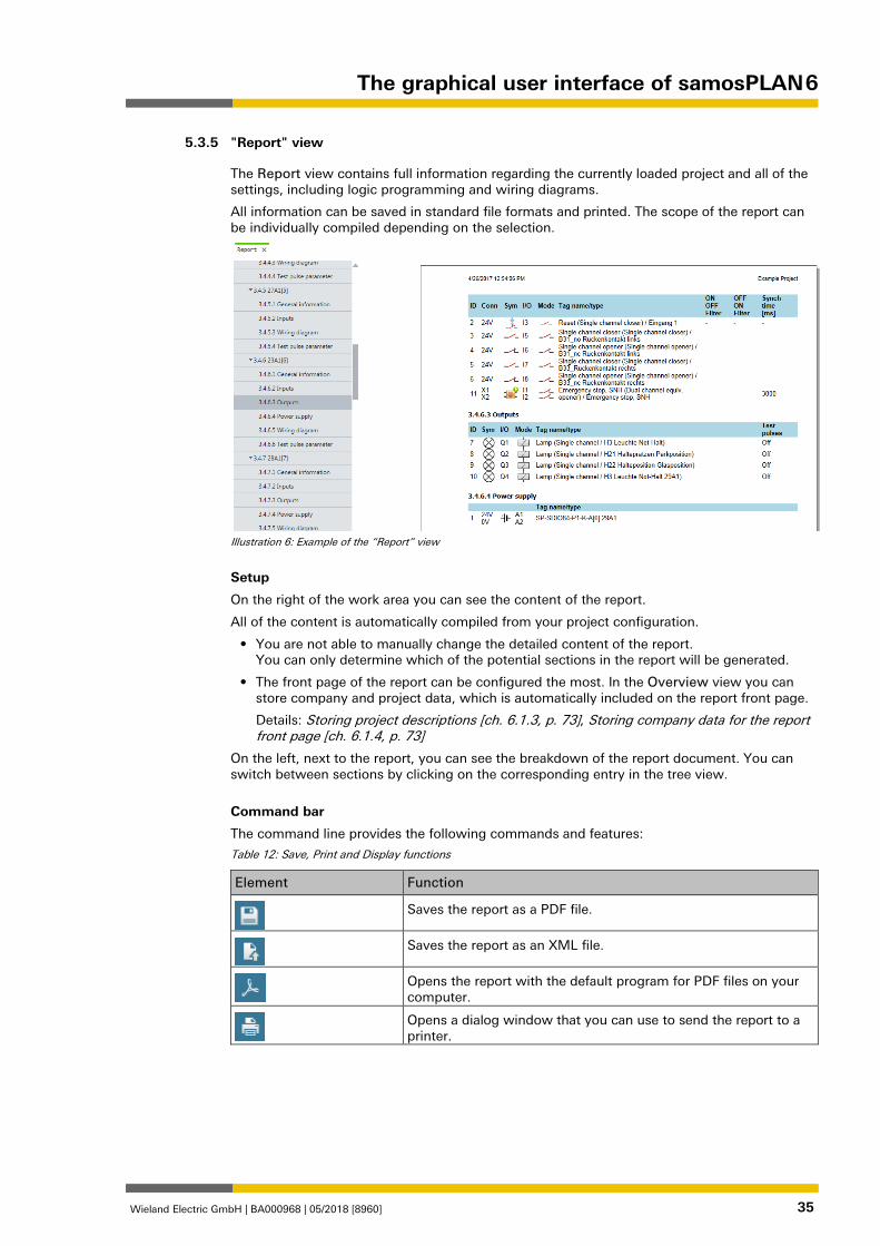
"Report" view 862997259
The Report view contains full information regarding the currently loaded project and all of the settings, including logic programming and wiring diagrams.
All information can be saved in standard file formats and printed. The scope of the report can be individually compiled depending on the selection.
Illustration 6: Example of the “Report” view
Setup
On the right of the work area you can see the content of the report.
All of the content is automatically compiled from your project configuration.
• You are not able to manually change the detailed content of the report. You can only determine which of the potential sections in the report will be generated.
• The front page of the report can be configured the most. In the Overview view you can store company and project data, which is automatically included on the report front page.
Details: Storing project descriptions [ch. 6.1.3, p. 73], Storing company data for the report front page [ch. 6.1.4, p. 73]
On the left, next to the report, you can see the breakdown of the report document. You can switch between sections by clicking on the corresponding entry in the tree view.
Command bar
The command line provides the following commands and features:
Table 12: Save, Print and Display functions
Element Function
Saves the report as a PDF file.
Saves the report as an XML file.
Opens the report with the default program for PDF files on your computer.
Opens a dialog window that you can use to send the report to a printer.
5.3.5
The graphical user interface of samosPLAN 6
Wieland Electric GmbH | BA000968 | 05/2018 [8960] 36
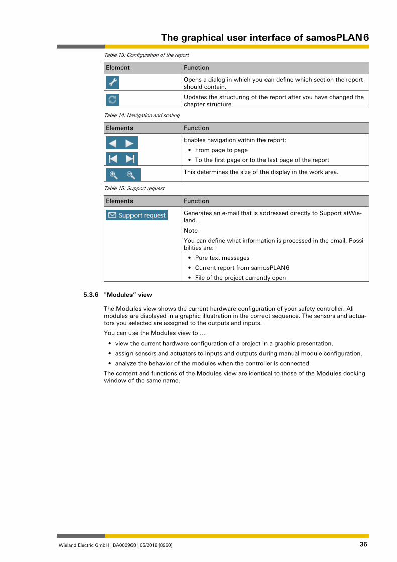
Table 13: Configuration of the report
Element Function
Opens a dialog in which you can define which section the report should contain.
Updates the structuring of the report after you have changed the chapter structure.
Table 14: Navigation and scaling
Elements Function
Enables navigation within the report:
• From page to page
• To the first page or to the last page of the report
This determines the size of the display in the work area.
Table 15: Support request
Elements Function
Generates an e-mail that is addressed directly to Support atWie-land. .
Note
You can define what information is processed in the email. Possi-bilities are:
• Pure text messages
• Current report from samosPLAN 6
• File of the project currently open
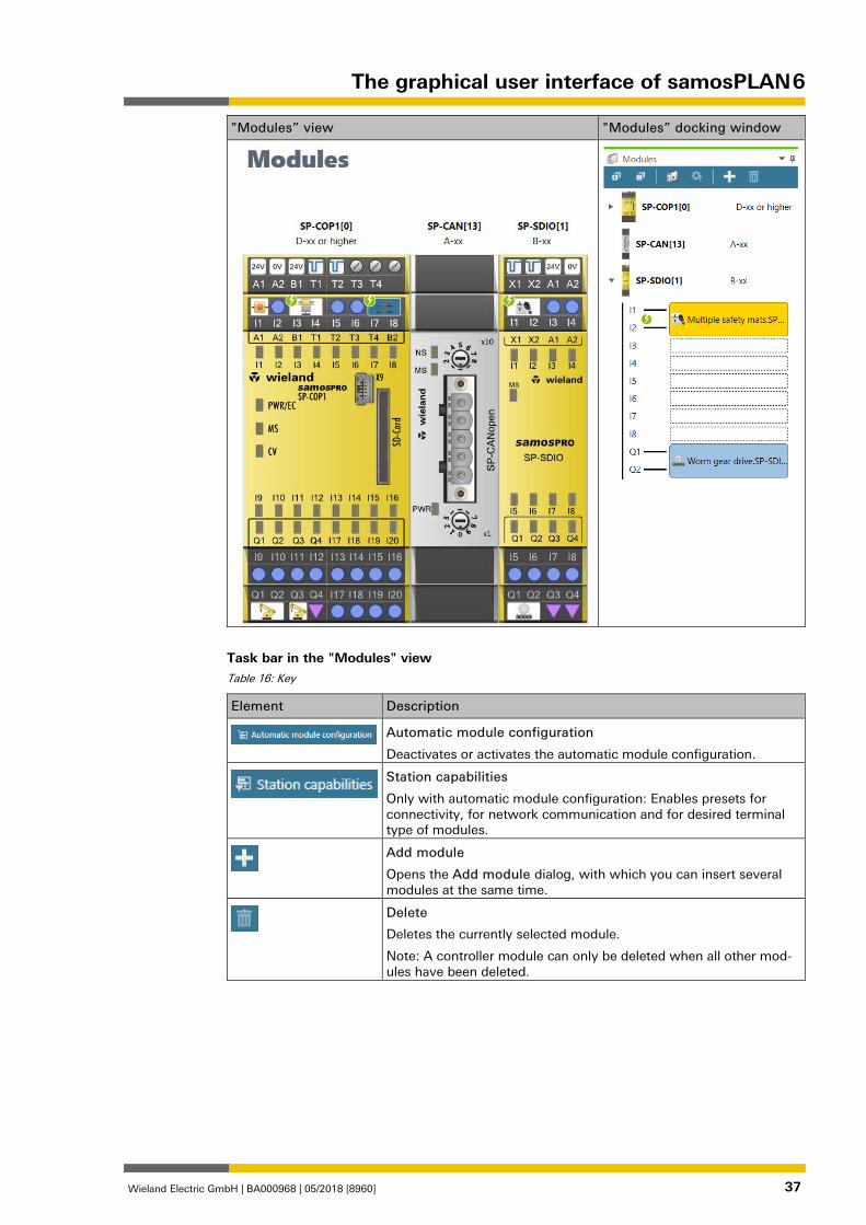
"Modules” view 1277517067
The Modules view shows the current hardware configuration of your safety controller. All modules are displayed in a graphic illustration in the correct sequence. The sensors and actua-tors you selected are assigned to the outputs and inputs.
You can use the Modules view to …
• view the current hardware configuration of a project in a graphic presentation,
• assign sensors and actuators to inputs and outputs during manual module configuration,
• analyze the behavior of the modules when the controller is connected.
The content and functions of the Modules view are identical to those of the Modules docking window of the same name.
5.3.6
The graphical user interface of samosPLAN 6
Wieland Electric GmbH | BA000968 | 05/2018 [8960] 37
"Modules” view "Modules” docking window
Task bar in the "Modules" view Table 16: Key
Element Description
Automatic module configuration
Deactivates or activates the automatic module configuration.
Station capabilities
Only with automatic module configuration: Enables presets for connectivity, for network communication and for desired terminal type of modules.
Add module
Opens the Add module dialog, with which you can insert several modules at the same time.
Delete
Deletes the currently selected module.
Note: A controller module can only be deleted when all other mod-ules have been deleted.
The graphical user interface of samosPLAN 6
Wieland Electric GmbH | BA000968 | 05/2018 [8960] 38
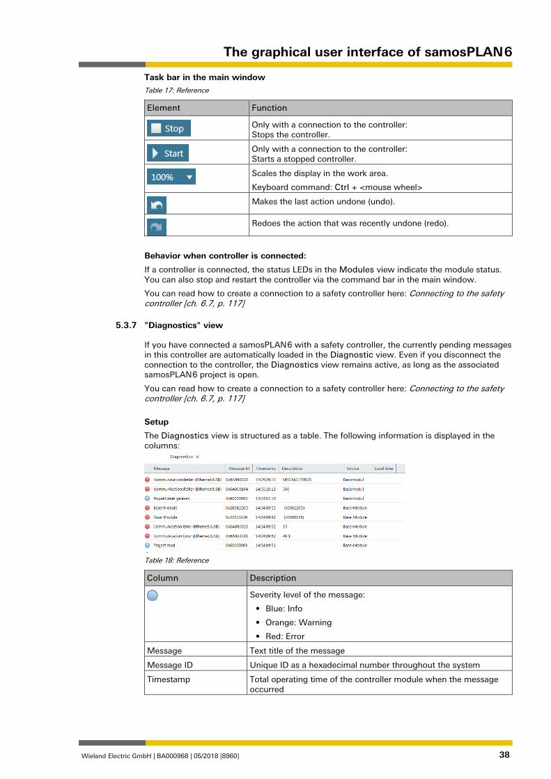
Task bar in the main window Table 17: Reference
Element Function
Only with a connection to the controller: Stops the controller.
Only with a connection to the controller: Starts a stopped controller.
Scales the display in the work area.
Keyboard command: Ctrl + <mouse wheel>
Makes the last action undone (undo).
Redoes the action that was recently undone (redo).
Behavior when controller is connected:
If a controller is connected, the status LEDs in the Modules view indicate the module status. You can also stop and restart the controller via the command bar in the main window.
You can read how to create a connection to a safety controller here: Connecting to the safety controller [ch. 6.7, p. 117]
"Diagnostics" view 879763595
If you have connected a samosPLAN 6 with a safety controller, the currently pending messages in this controller are automatically loaded in the Diagnostic view. Even if you disconnect the connection to the controller, the Diagnostics view remains active, as long as the associated samosPLAN 6 project is open.
You can read how to create a connection to a safety controller here: Connecting to the safety controller [ch. 6.7, p. 117]
Setup
The Diagnostics view is structured as a table. The following information is displayed in the columns:
Table 18: Reference
Column Description
Severity level of the message:
• Blue: Info
• Orange: Warning
• Red: Error
Message Text title of the message
Message ID Unique ID as a hexadecimal number throughout the system
Timestamp Total operating time of the controller module when the message occurred
5.3.7
The graphical user interface of samosPLAN 6
Wieland Electric GmbH | BA000968 | 05/2018 [8960] 39
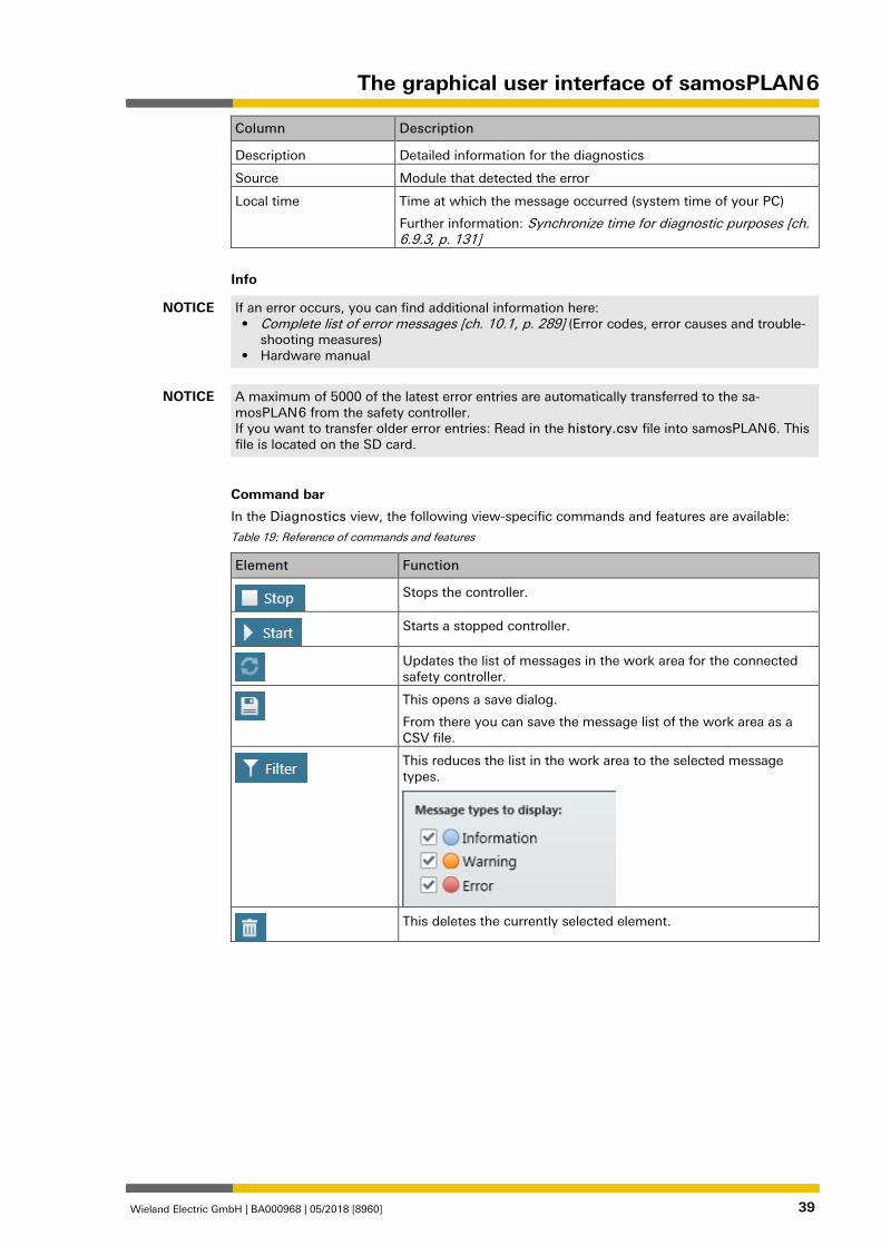
Column Description
Description Detailed information for the diagnostics
Source Module that detected the error
Local time Time at which the message occurred (system time of your PC)
Further information: Synchronize time for diagnostic purposes [ch. 6.9.3, p. 131]
Info
NOTICE If an error occurs, you can find additional information here: • Complete list of error messages [ch. 10.1, p. 289] (Error codes, error causes and trouble-
shooting measures) • Hardware manual
NOTICE A maximum of 5000 of the latest error entries are automatically transferred to the sa-mosPLAN 6 from the safety controller. If you want to transfer older error entries: Read in the history.csv file into samosPLAN 6. This file is located on the SD card.
Command bar
In the Diagnostics view, the following view-specific commands and features are available:
Table 19: Reference of commands and features
Element Function
Stops the controller.
Starts a stopped controller.
Updates the list of messages in the work area for the connected safety controller.
This opens a save dialog.
From there you can save the message list of the work area as a CSV file.
This reduces the list in the work area to the selected message types.
This deletes the currently selected element.
The graphical user interface of samosPLAN 6
Wieland Electric GmbH | BA000968 | 05/2018 [8960] 40
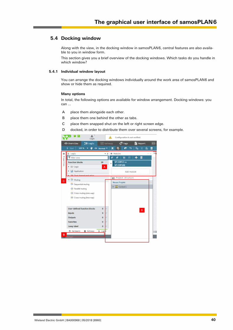
Docking window 1276695307
Along with the view, in the docking window in samosPLAN 6, central features are also availa-ble to you in window form.
This section gives you a brief overview of the docking windows. Which tasks do you handle in which window?
Individual window layout 1277800459
You can arrange the docking windows individually around the work area of samosPLAN 6 and show or hide them as required.
Many options
In total, the following options are available for window arrangement. Docking windows: you can ...
A place them alongside each other.
B place them one behind the other as tabs.
C place them snapped shut on the left or right screen edge.
D docked, in order to distribute them over several screens, for example.
5.4
5.4.1
The graphical user interface of samosPLAN 6
Wieland Electric GmbH | BA000968 | 05/2018 [8960] 41
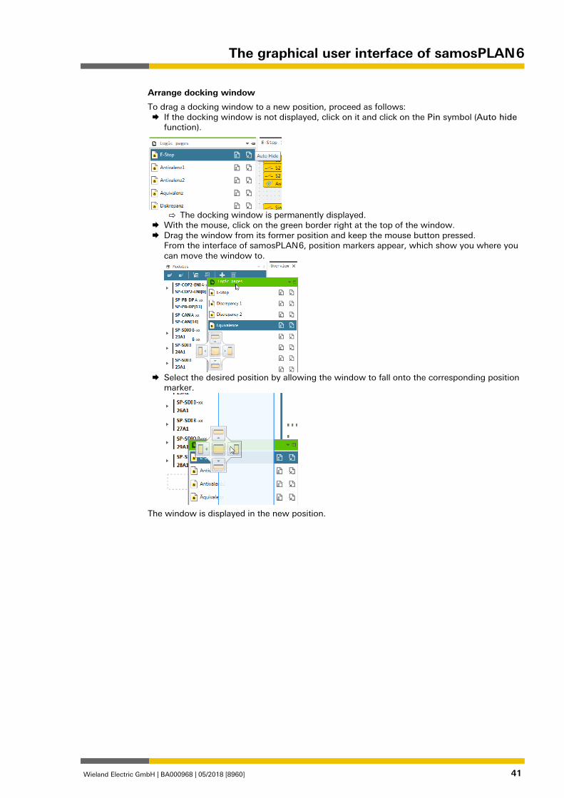
Arrange docking window
To drag a docking window to a new position, proceed as follows: If the docking window is not displayed, click on it and click on the Pin symbol (Auto hide
function).
⇨ The docking window is permanently displayed.
With the mouse, click on the green border right at the top of the window. Drag the window from its former position and keep the mouse button pressed.
From the interface of samosPLAN 6, position markers appear, which show you where you can move the window to.
Select the desired position by allowing the window to fall onto the corresponding position
marker.
The window is displayed in the new position.
The graphical user interface of samosPLAN 6
Wieland Electric GmbH | BA000968 | 05/2018 [8960] 42
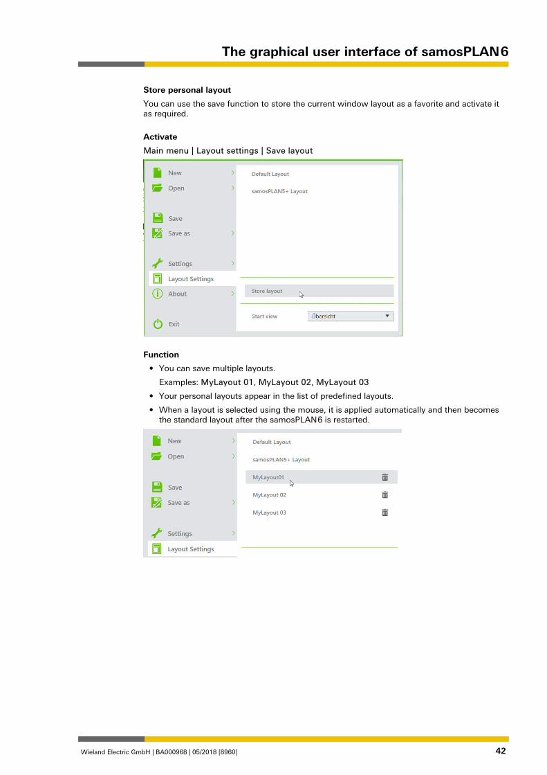
Store personal layout
You can use the save function to store the current window layout as a favorite and activate it as required.
Activate
Main menu | Layout settings | Save layout
Function
• You can save multiple layouts.
Examples: MyLayout 01, MyLayout 02, MyLayout 03
• Your personal layouts appear in the list of predefined layouts.
• When a layout is selected using the mouse, it is applied automatically and then becomes the standard layout after the samosPLAN 6 is restarted.
The graphical user interface of samosPLAN 6
Wieland Electric GmbH | BA000968 | 05/2018 [8960] 43
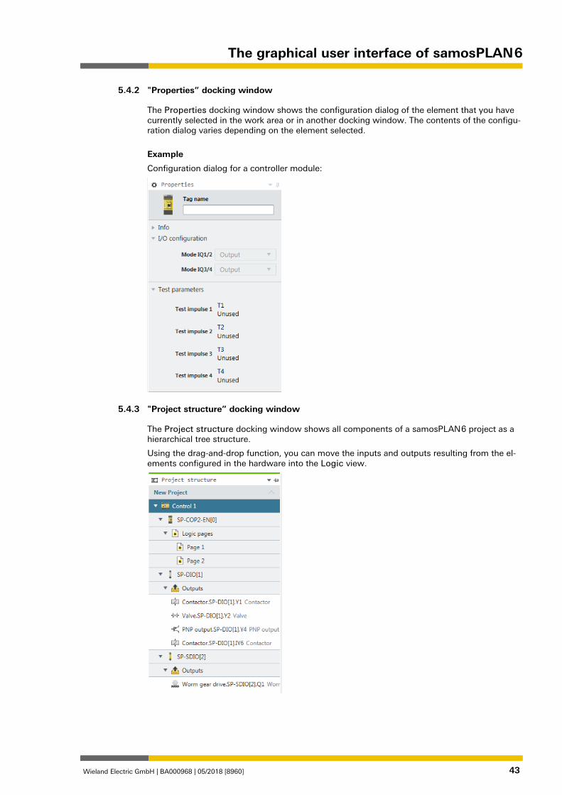
"Properties” docking window 1276755723
The Properties docking window shows the configuration dialog of the element that you have currently selected in the work area or in another docking window. The contents of the configu-ration dialog varies depending on the element selected.
Example
Configuration dialog for a controller module:
"Project structure” docking window 1276713355
The Project structure docking window shows all components of a samosPLAN 6 project as a hierarchical tree structure.
Using the drag-and-drop function, you can move the inputs and outputs resulting from the el-ements configured in the hardware into the Logic view.
5.4.2
5.4.3
The graphical user interface of samosPLAN 6
Wieland Electric GmbH | BA000968 | 05/2018 [8960] 44
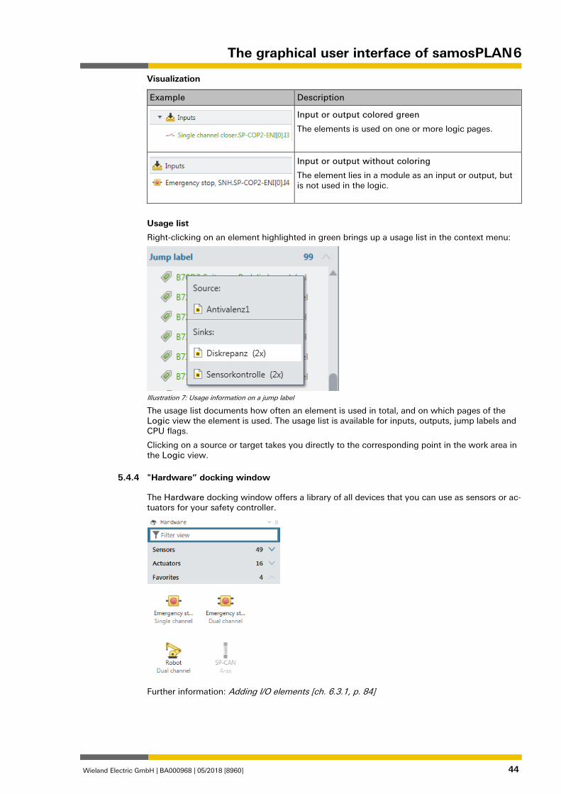
Visualization
Example Description
Input or output colored green
The elements is used on one or more logic pages.
Input or output without coloring
The element lies in a module as an input or output, but is not used in the logic.
Usage list
Right-clicking on an element highlighted in green brings up a usage list in the context menu:
Illustration 7: Usage information on a jump label
The usage list documents how often an element is used in total, and on which pages of the Logic view the element is used. The usage list is available for inputs, outputs, jump labels and CPU flags.
Clicking on a source or target takes you directly to the corresponding point in the work area in the Logic view.
"Hardware” docking window 1276763787
The Hardware docking window offers a library of all devices that you can use as sensors or ac-tuators for your safety controller.
Further information: Adding I/O elements [ch. 6.3.1, p. 84]
5.4.4
The graphical user interface of samosPLAN 6
Wieland Electric GmbH | BA000968 | 05/2018 [8960] 45
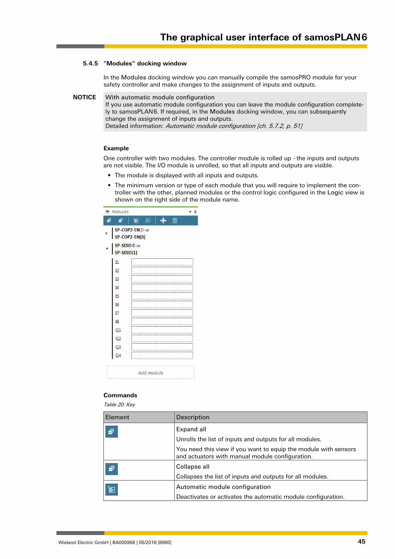
"Modules” docking window 1276778891
In the Modules docking window you can manually compile the samosPRO module for your safety controller and make changes to the assignment of inputs and outputs.
NOTICE With automatic module configuration If you use automatic module configuration you can leave the module configuration complete-ly to samosPLAN 6. If required, in the Modules docking window, you can subsequently change the assignment of inputs and outputs. Detailed information: Automatic module configuration [ch. 5.7.2, p. 51]
Example
One controller with two modules. The controller module is rolled up - the inputs and outputs are not visible. The I/O module is unrolled, so that all inputs and outputs are visible.
• The module is displayed with all inputs and outputs.
• The minimum version or type of each module that you will require to implement the con-troller with the other, planned modules or the control logic configured in the Logic view is shown on the right side of the module name.
Commands Table 20: Key
Element Description
Expand all
Unrolls the list of inputs and outputs for all modules.
You need this view if you want to equip the module with sensors and actuators with manual module configuration.
Collapse all
Collapses the list of inputs and outputs for all modules.
Automatic module configuration
Deactivates or activates the automatic module configuration.
5.4.5
The graphical user interface of samosPLAN 6
Wieland Electric GmbH | BA000968 | 05/2018 [8960] 46
Element Description
Station capability
Only with automatic module configuration: Enables presets for connectivity, for network communication and for desired terminal type of modules.
Add module
Opens the Add module dialog, with which you can insert several modules at the same time.
Delete
Deletes the currently selected module.
Note: A controller module can only be deleted when all other mod-ules have been deleted.
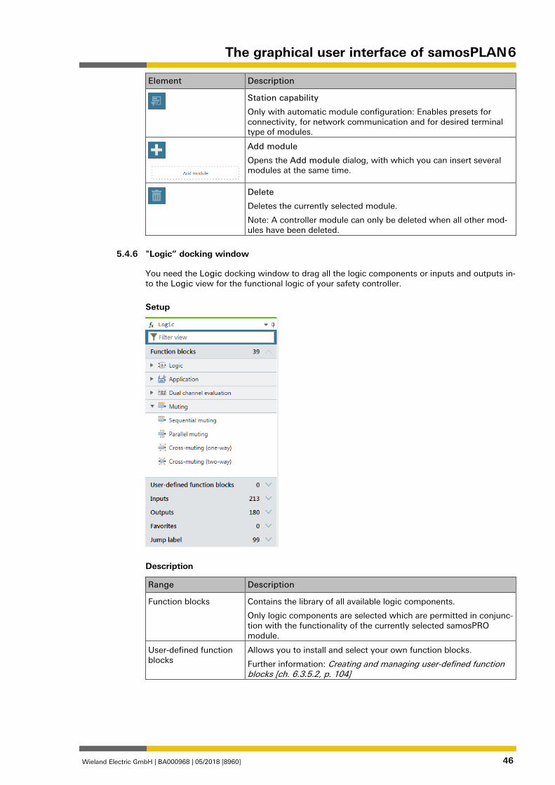
"Logic” docking window 1276822027
You need the Logic docking window to drag all the logic components or inputs and outputs in-to the Logic view for the functional logic of your safety controller.
Setup
Description
Range Description
Function blocks Contains the library of all available logic components.
Only logic components are selected which are permitted in conjunc-tion with the functionality of the currently selected samosPRO module.
User-defined function blocks
Allows you to install and select your own function blocks.
Further information: Creating and managing user-defined function blocks [ch. 6.3.5.2, p. 104]
5.4.6
The graphical user interface of samosPLAN 6
Wieland Electric GmbH | BA000968 | 05/2018 [8960] 47
Range Description
Inputs / outputs Shows all inputs and outputs currently linked with sensors or actua-tors
Favorites Allows you to define favorites for frequently required elements from the Logic docking window.
Further information: Favorites for hardware and logic [ch. 5.4.9, p. 48]
Jump labels Further information: Jump addresses [ch. 6.3.1.4, p. 91]
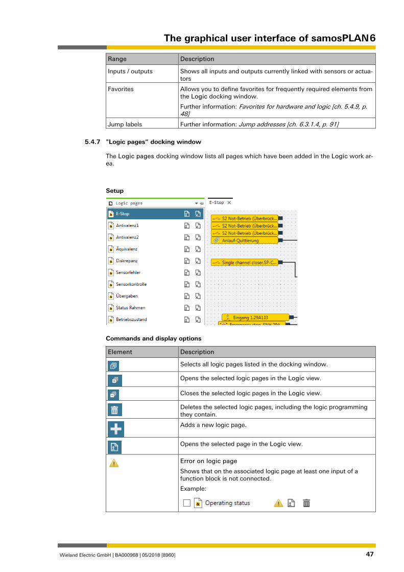
"Logic pages” docking window 1276844555
The Logic pages docking window lists all pages which have been added in the Logic work ar-ea.
Setup
Commands and display options
Element Description
Selects all logic pages listed in the docking window.
Opens the selected logic pages in the Logic view.
Closes the selected logic pages in the Logic view.
Deletes the selected logic pages, including the logic programming they contain.
Adds a new logic page.
Opens the selected page in the Logic view.
Error on logic page
Shows that on the associated logic page at least one input of a function block is not connected.
Example:
5.4.7
The graphical user interface of samosPLAN 6
Wieland Electric GmbH | BA000968 | 05/2018 [8960] 48
"Gateway” docking window 1276870155
You can find detailed information regarding the Gateway docking window here:
Gateway manual, Chapter "Configuration of gateways with samosPLAN6"
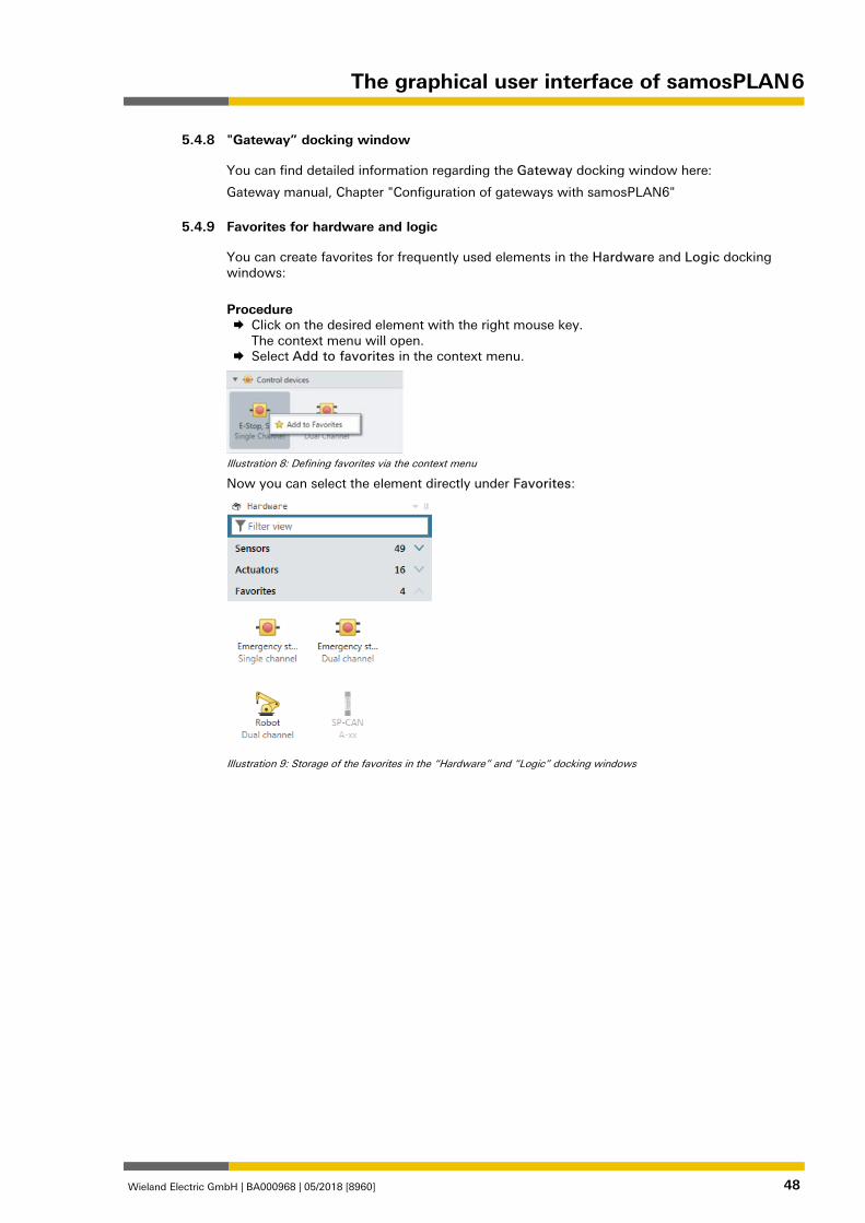
Favorites for hardware and logic 862882699
You can create favorites for frequently used elements in the Hardware and Logic docking windows:
Procedure Click on the desired element with the right mouse key.
The context menu will open. Select Add to favorites in the context menu.
Illustration 8: Defining favorites via the context menu
Now you can select the element directly under Favorites:
Illustration 9: Storage of the favorites in the “Hardware” and “Logic” docking windows
5.4.8
5.4.9
The graphical user interface of samosPLAN 6
Wieland Electric GmbH | BA000968 | 05/2018 [8960] 49
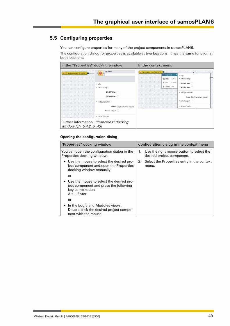
Configuring properties 1383878667
You can configure properties for many of the project components in samosPLAN 6.
The configuration dialog for properties is available at two locations. It has the same function at both locations:
In the "Properties” docking window In the context menu
Further information: "Properties” docking window [ch. 5.4.2, p. 43]
Opening the configuration dialog
"Properties” docking window Configuration dialog in the context menu
You can open the configuration dialog in the Properties docking window:
• Use the mouse to select the desired pro-ject component and open the Properties docking window manually.
or
• Use the mouse to select the desired pro-ject component and press the following key combination. Alt + Enter
or
• In the Logic and Modules views: Double-click the desired project compo-nent with the mouse.
1. Use the right mouse button to select the desired project component.
2. Select the Properties entry in the context menu.
5.5
The graphical user interface of samosPLAN 6
Wieland Electric GmbH | BA000968 | 05/2018 [8960] 50
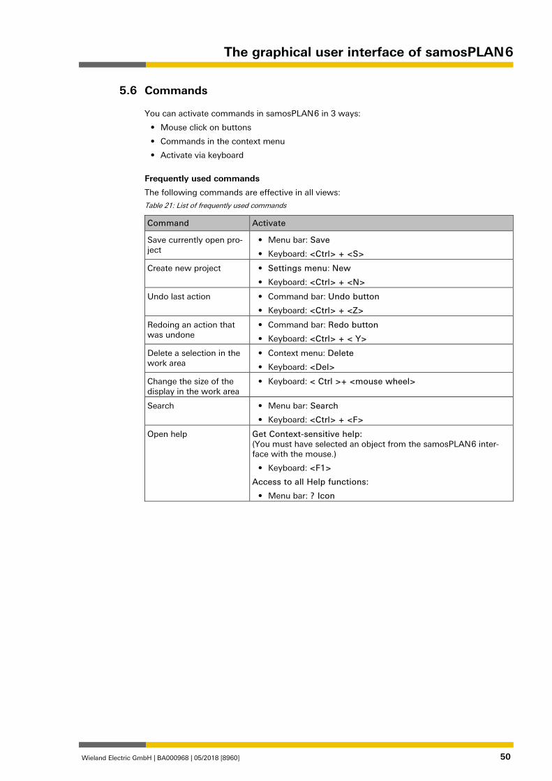
Commands 862881163
You can activate commands in samosPLAN 6 in 3 ways:
• Mouse click on buttons
• Commands in the context menu
• Activate via keyboard
Frequently used commands
The following commands are effective in all views:
Table 21: List of frequently used commands
Command Activate
Save currently open pro-ject
• Menu bar: Save
• Keyboard: <Ctrl> + <S>
Create new project • Settings menu: New
• Keyboard: <Ctrl> + <N>
Undo last action • Command bar: Undo button
• Keyboard: <Ctrl> + <Z>
Redoing an action that was undone
• Command bar: Redo button
• Keyboard: <Ctrl> + < Y>
Delete a selection in the work area
• Context menu: Delete
• Keyboard: <Del>
Change the size of the display in the work area
• Keyboard: < Ctrl >+ <mouse wheel>
Search • Menu bar: Search
• Keyboard: <Ctrl> + <F>
Open help Get Context-sensitive help: (You must have selected an object from the samosPLAN 6 inter-face with the mouse.)
• Keyboard: <F1>
Access to all Help functions:
• Menu bar: ? Icon
5.6
The graphical user interface of samosPLAN 6
Wieland Electric GmbH | BA000968 | 05/2018 [8960] 51
Module configuration options 1392886283
In samosPLAN 6, you have two options for selecting and configuring the modules required for safety controllers. You use either automatic module configuration or you decide to use (classic) manual module configuration.
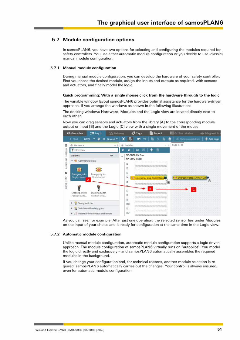
Manual module configuration 1273995915
During manual module configuration, you can develop the hardware of your safety controller. First you chose the desired module, assign the inputs and outputs as required, with sensors and actuators, and finally model the logic.
Quick programming: With a single mouse click from the hardware through to the logic
The variable window layout samosPLAN 6 provides optimal assistance for the hardware-driven approach. If you arrange the windows as shown in the following illustration:
The docking windows Hardware, Modules and the Logic view are located directly next to each other.
Now you can drag sensors and actuators from the library [A] to the corresponding module output or input [B] and the Logic [C] view with a single movement of the mouse.
As you can see, for example: After just one operation, the selected sensor lies under Modules on the input of your choice and is ready for configuration at the same time in the Logic view.
Automatic module configuration 1273998859
Unlike manual module configuration, automatic module configuration supports a logic-driven approach. The module configuration of samosPLAN 6 virtually runs on "autopilot": You model the logic directly and exclusively – and samosPLAN 6 automatically assembles the required modules in the background.
If you change your configuration and, for technical reasons, another module selection is re-quired, samosPLAN 6 automatically carries out the changes. Your control is always ensured, even for automatic module configuration.
5.7
5.7.1
5.7.2
The graphical user interface of samosPLAN 6
Wieland Electric GmbH | BA000968 | 05/2018 [8960] 52
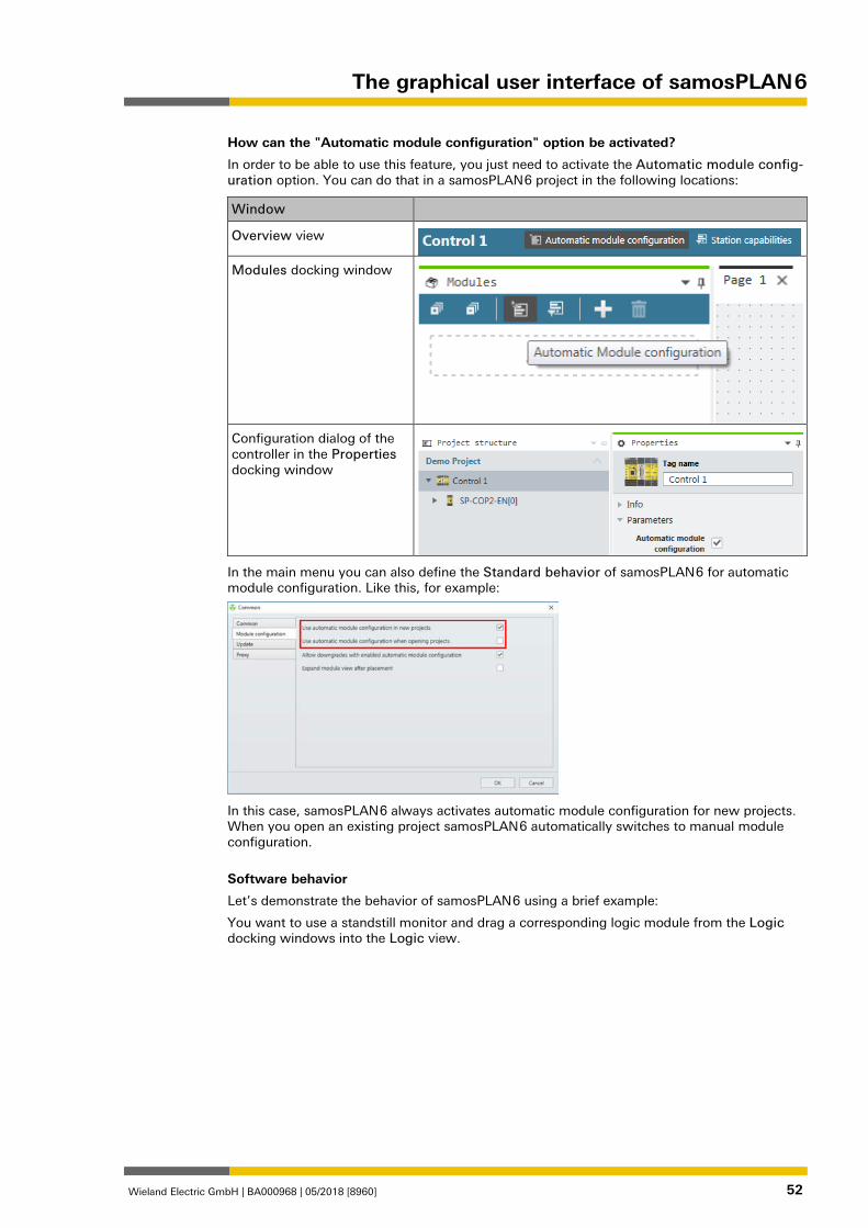
How can the "Automatic module configuration" option be activated?
In order to be able to use this feature, you just need to activate the Automatic module config-uration option. You can do that in a samosPLAN 6 project in the following locations:
Window
Overview view
Modules docking window
Configuration dialog of the controller in the Properties docking window
In the main menu you can also define the Standard behavior of samosPLAN 6 for automatic module configuration. Like this, for example:
In this case, samosPLAN 6 always activates automatic module configuration for new projects. When you open an existing project samosPLAN 6 automatically switches to manual module configuration.
Software behavior
Let’s demonstrate the behavior of samosPLAN 6 using a brief example:
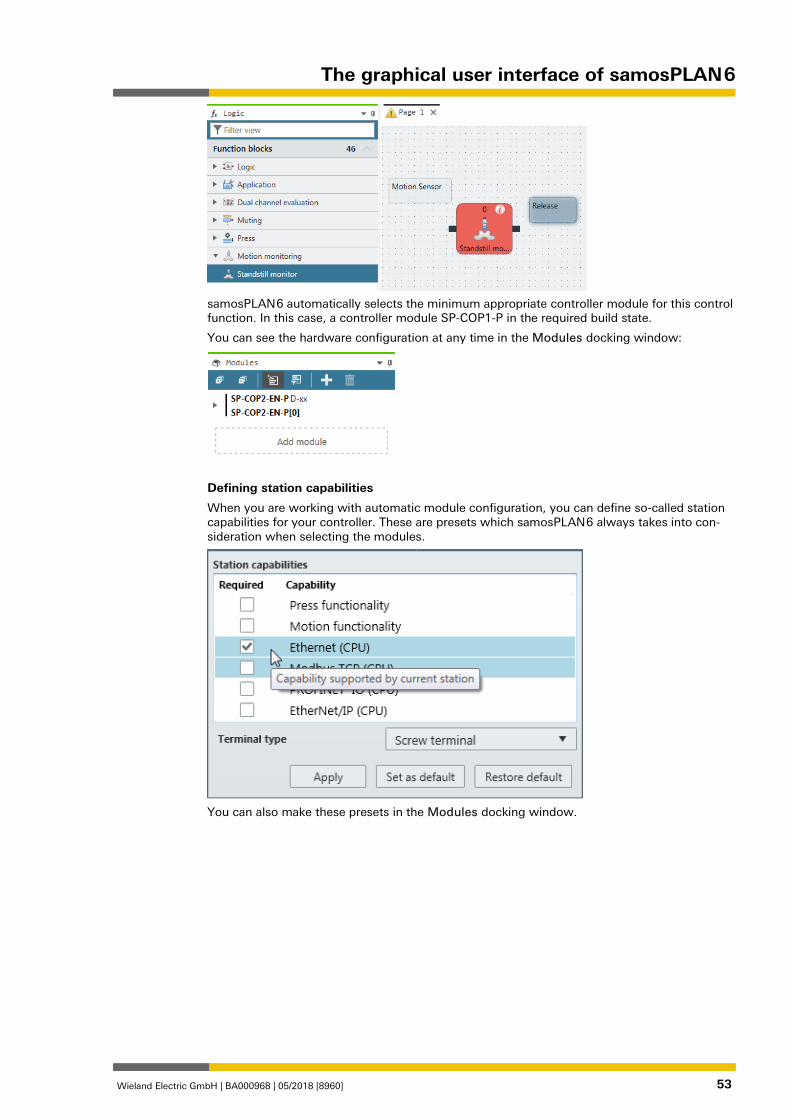
You want to use a standstill monitor and drag a corresponding logic module from the Logic docking windows into the Logic view.
The graphical user interface of samosPLAN 6
Wieland Electric GmbH | BA000968 | 05/2018 [8960] 53
samosPLAN 6 automatically selects the minimum appropriate controller module for this control function. In this case, a controller module SP-COP1-P in the required build state.
You can see the hardware configuration at any time in the Modules docking window:
Defining station capabilities
When you are working with automatic module configuration, you can define so-called station capabilities for your controller. These are presets which samosPLAN 6 always takes into con-sideration when selecting the modules.
You can also make these presets in the Modules docking window.
The graphical user interface of samosPLAN 6
Wieland Electric GmbH | BA000968 | 05/2018 [8960] 54
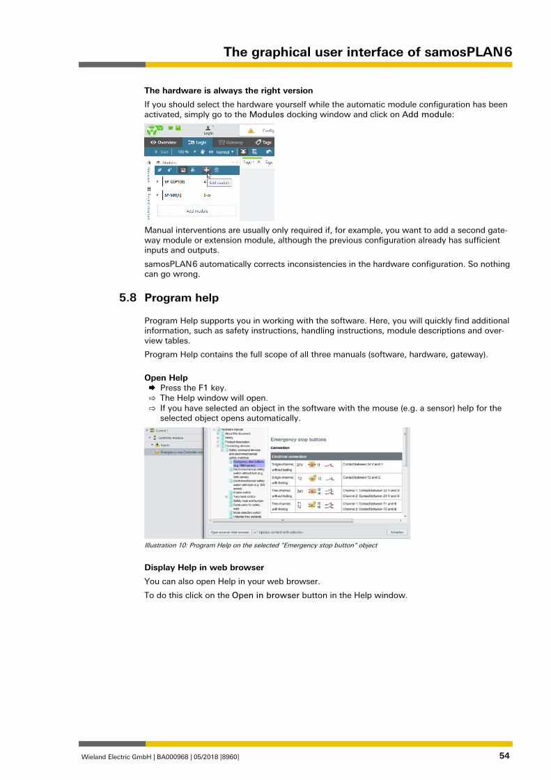
The hardware is always the right version
If you should select the hardware yourself while the automatic module configuration has been activated, simply go to the Modules docking window and click on Add module:
Manual interventions are usually only required if, for example, you want to add a second gate-way module or extension module, although the previous configuration already has sufficient inputs and outputs.
samosPLAN 6 automatically corrects inconsistencies in the hardware configuration. So nothing can go wrong.
Program help 954845451
Program Help supports you in working with the software. Here, you will quickly find additional information, such as safety instructions, handling instructions, module descriptions and over-view tables.
Program Help contains the full scope of all three manuals (software, hardware, gateway).
Open Help Press the F1 key.
⇨ The Help window will open. ⇨ If you have selected an object in the software with the mouse (e.g. a sensor) help for the
selected object opens automatically.
Illustration 10: Program Help on the selected "Emergency stop button" object
Display Help in web browser
You can also open Help in your web browser.
To do this click on the Open in browser button in the Help window.
5.8

The graphical user interface of samosPLAN 6
Wieland Electric GmbH | BA000968 | 05/2018 [8960] 55
Settings and functions across projects (main menu) 862888075
The main menu offers numerous options for adapting the user interface and the behavior of samosPLAN 6 to suit your individual requirements.
The following commands and functions are available for all projects:
Illustration 11: Main menu of samosPLAN 6
5.9
The graphical user interface of samosPLAN 6
Wieland Electric GmbH | BA000968 | 05/2018 [8960] 56
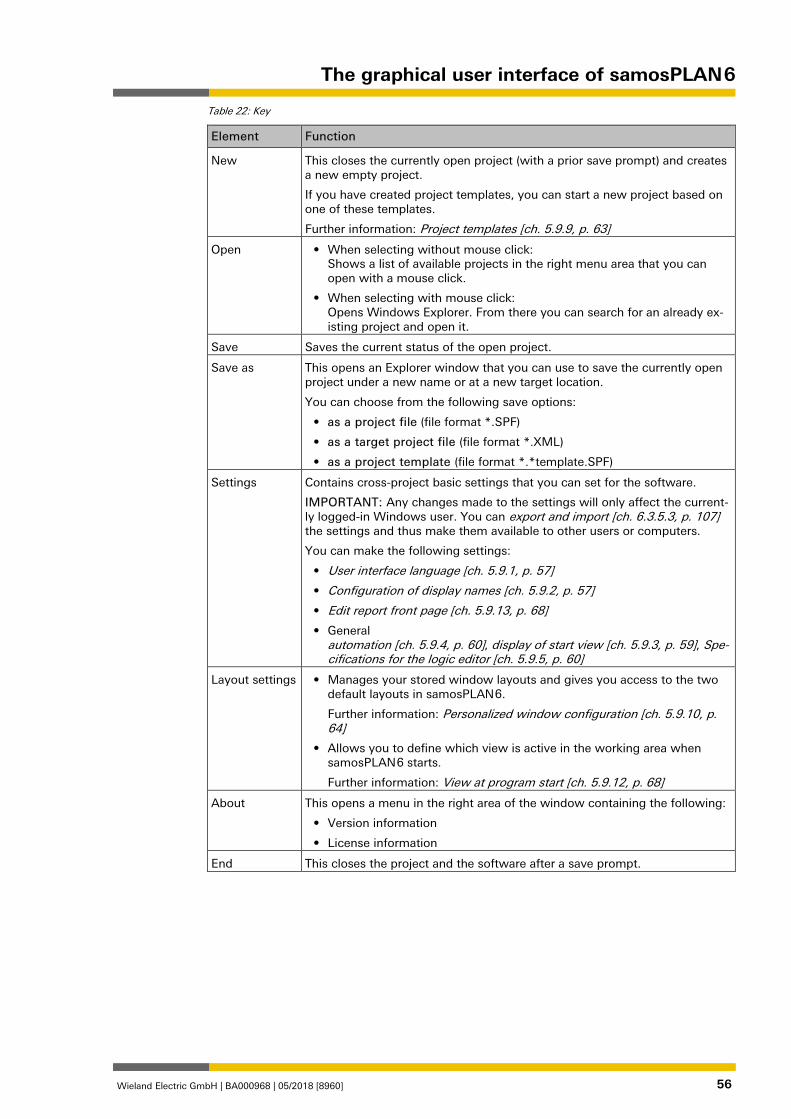
Table 22: Key
Element Function
New This closes the currently open project (with a prior save prompt) and creates a new empty project.
If you have created project templates, you can start a new project based on one of these templates.
Further information: Project templates [ch. 5.9.9, p. 63]
Open • When selecting without mouse click: Shows a list of available projects in the right menu area that you can open with a mouse click.
• When selecting with mouse click: Opens Windows Explorer. From there you can search for an already ex-isting project and open it.
Save Saves the current status of the open project.
Save as This opens an Explorer window that you can use to save the currently open project under a new name or at a new target location.
You can choose from the following save options:
• as a project file (file format *.SPF)
• as a target project file (file format *.XML)
• as a project template (file format *.*template.SPF)
Settings Contains cross-project basic settings that you can set for the software.
IMPORTANT: Any changes made to the settings will only affect the current-ly logged-in Windows user. You can export and import [ch. 6.3.5.3, p. 107] the settings and thus make them available to other users or computers.
You can make the following settings:
• User interface language [ch. 5.9.1, p. 57]
• Configuration of display names [ch. 5.9.2, p. 57]
• Edit report front page [ch. 5.9.13, p. 68]
• General automation [ch. 5.9.4, p. 60], display of start view [ch. 5.9.3, p. 59], Spe-cifications for the logic editor [ch. 5.9.5, p. 60]
Layout settings • Manages your stored window layouts and gives you access to the two default layouts in samosPLAN 6.
Further information: Personalized window configuration [ch. 5.9.10, p. 64]
• Allows you to define which view is active in the working area when samosPLAN 6 starts.
Further information: View at program start [ch. 5.9.12, p. 68]
About This opens a menu in the right area of the window containing the following:
• Version information
• License information
End This closes the project and the software after a save prompt.
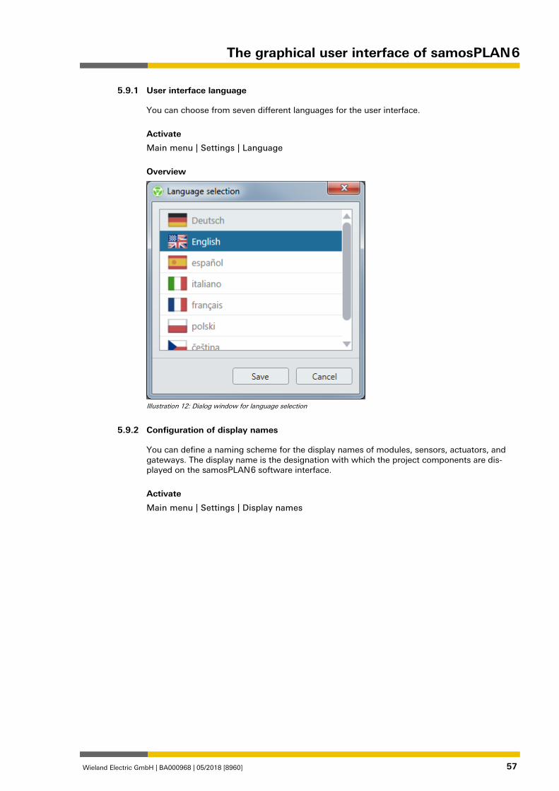
The graphical user interface of samosPLAN 6
Wieland Electric GmbH | BA000968 | 05/2018 [8960] 57
User interface language 862890763
You can choose from seven different languages for the user interface.
Activate
Main menu | Settings | Language
Overview
Illustration 12: Dialog window for language selection
Configuration of display names 862893451
You can define a naming scheme for the display names of modules, sensors, actuators, and gateways. The display name is the designation with which the project components are dis-played on the samosPLAN 6 software interface.
Activate
Main menu | Settings | Display names
5.9.1
5.9.2
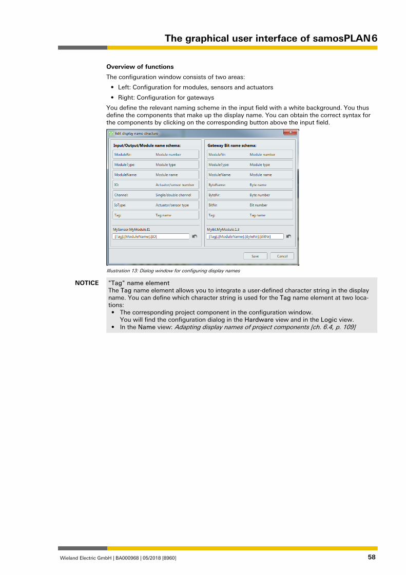
The graphical user interface of samosPLAN 6
Wieland Electric GmbH | BA000968 | 05/2018 [8960] 58
Overview of functions
The configuration window consists of two areas:
• Left: Configuration for modules, sensors and actuators
• Right: Configuration for gateways
You define the relevant naming scheme in the input field with a white background. You thus define the components that make up the display name. You can obtain the correct syntax for the components by clicking on the corresponding button above the input field.
Illustration 13: Dialog window for configuring display names
NOTICE "Tag" name element The Tag name element allows you to integrate a user-defined character string in the display name. You can define which character string is used for the Tag name element at two loca-tions: • The corresponding project component in the configuration window.
You will find the configuration dialog in the Hardware view and in the Logic view. • In the Name view: Adapting display names of project components [ch. 6.4, p. 109]
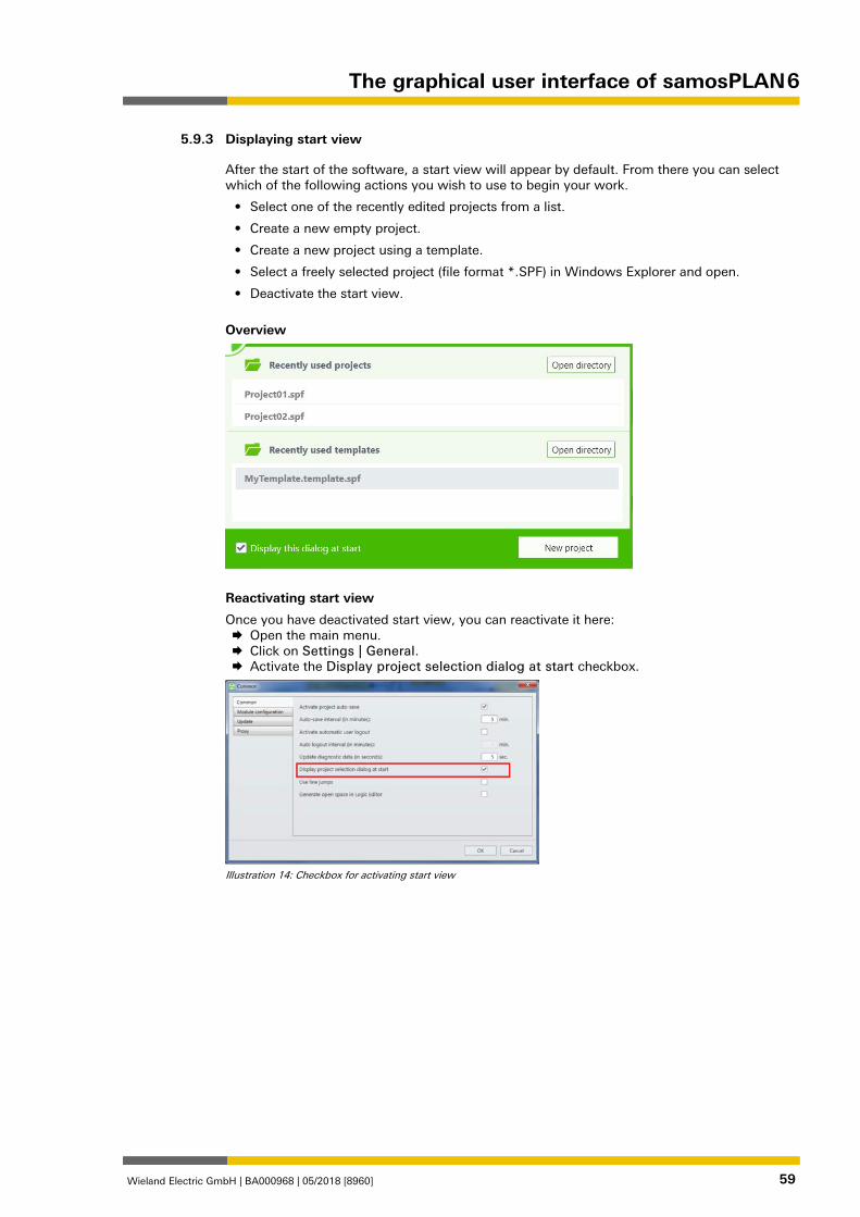
The graphical user interface of samosPLAN 6
Wieland Electric GmbH | BA000968 | 05/2018 [8960] 59
Displaying start view 862896139
After the start of the software, a start view will appear by default. From there you can select which of the following actions you wish to use to begin your work.
• Select one of the recently edited projects from a list.
• Create a new empty project.
• Create a new project using a template.
• Select a freely selected project (file format *.SPF) in Windows Explorer and open.
• Deactivate the start view.
Overview
Reactivating start view
Once you have deactivated start view, you can reactivate it here: Open the main menu. Click on Settings | General. Activate the Display project selection dialog at start checkbox.
Illustration 14: Checkbox for activating start view
5.9.3
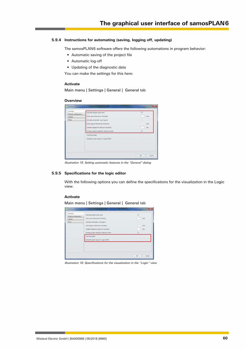
The graphical user interface of samosPLAN 6
Wieland Electric GmbH | BA000968 | 05/2018 [8960] 60
Instructions for automating (saving, logging off, updating) 862900491
The samosPLAN 6 software offers the following automations in program behavior:
• Automatic saving of the project file
• Automatic log-off
• Updating of the diagnostic data
You can make the settings for this here:
Activate
Main menu | Settings | General | General tab
Overview
Illustration 15: Setting automatic features in the "General" dialog
Specifications for the logic editor 955604491
With the following options you can define the specifications for the visualization in the Logic view.
Activate
Main menu | Settings | General | General tab
Illustration 16: Specifications for the visualization in the “Logic” view
5.9.4
5.9.5
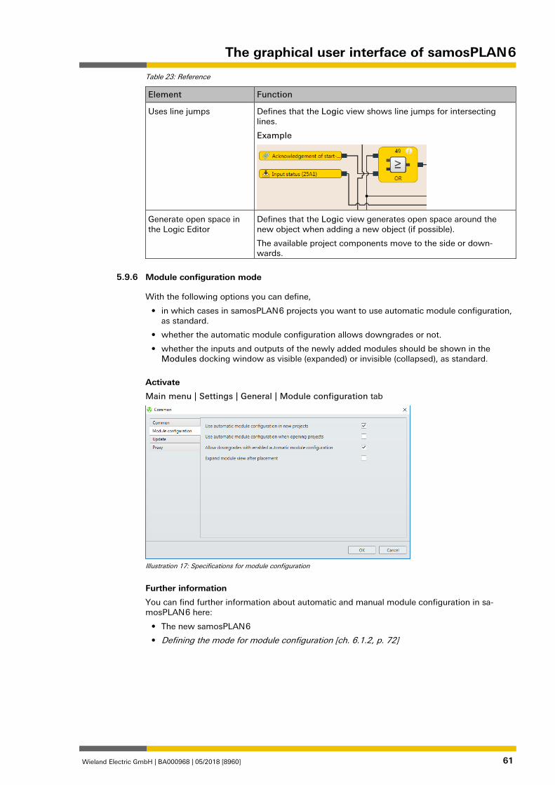
The graphical user interface of samosPLAN 6
Wieland Electric GmbH | BA000968 | 05/2018 [8960] 61
Table 23: Reference
Element Function
Uses line jumps Defines that the Logic view shows line jumps for intersecting lines.
Example
Generate open space in the Logic Editor
Defines that the Logic view generates open space around the new object when adding a new object (if possible).
The available project components move to the side or down-wards.
Module configuration mode 1282668171
With the following options you can define,
• in which cases in samosPLAN 6 projects you want to use automatic module configuration, as standard.
• whether the automatic module configuration allows downgrades or not.
• whether the inputs and outputs of the newly added modules should be shown in the Modules docking window as visible (expanded) or invisible (collapsed), as standard.
Activate
Main menu | Settings | General | Module configuration tab
Illustration 17: Specifications for module configuration
Further information
You can find further information about automatic and manual module configuration in sa-mosPLAN 6 here:
• The new samosPLAN 6
• Defining the mode for module configuration [ch. 6.1.2, p. 72]
5.9.6
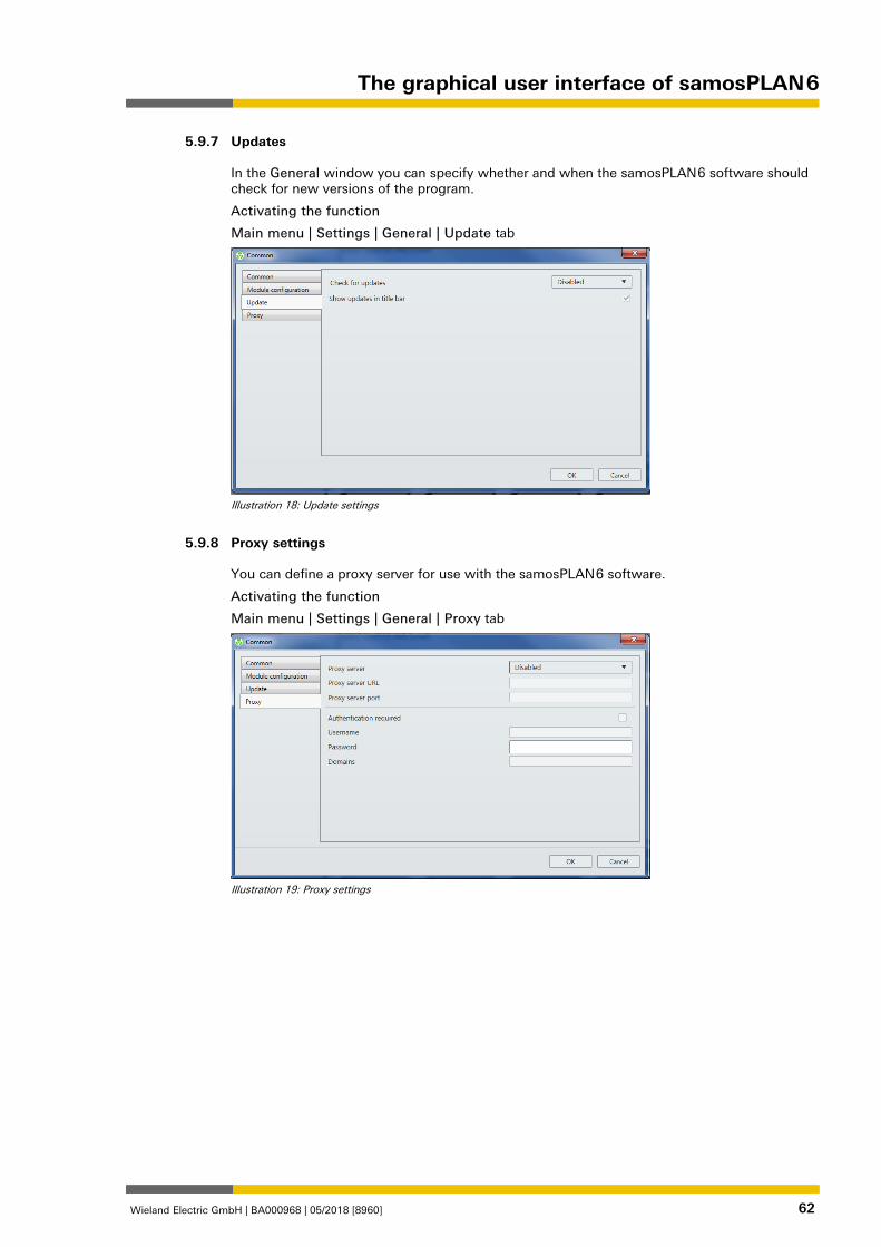
The graphical user interface of samosPLAN 6
Wieland Electric GmbH | BA000968 | 05/2018 [8960] 62
Updates 1120109579
In the General window you can specify whether and when the samosPLAN 6 software should check for new versions of the program.
Activating the function
Main menu | Settings | General | Update tab
Illustration 18: Update settings
Proxy settings 1120124555
You can define a proxy server for use with the samosPLAN 6 software.
Activating the function
Main menu | Settings | General | Proxy tab
Illustration 19: Proxy settings
5.9.7
5.9.8
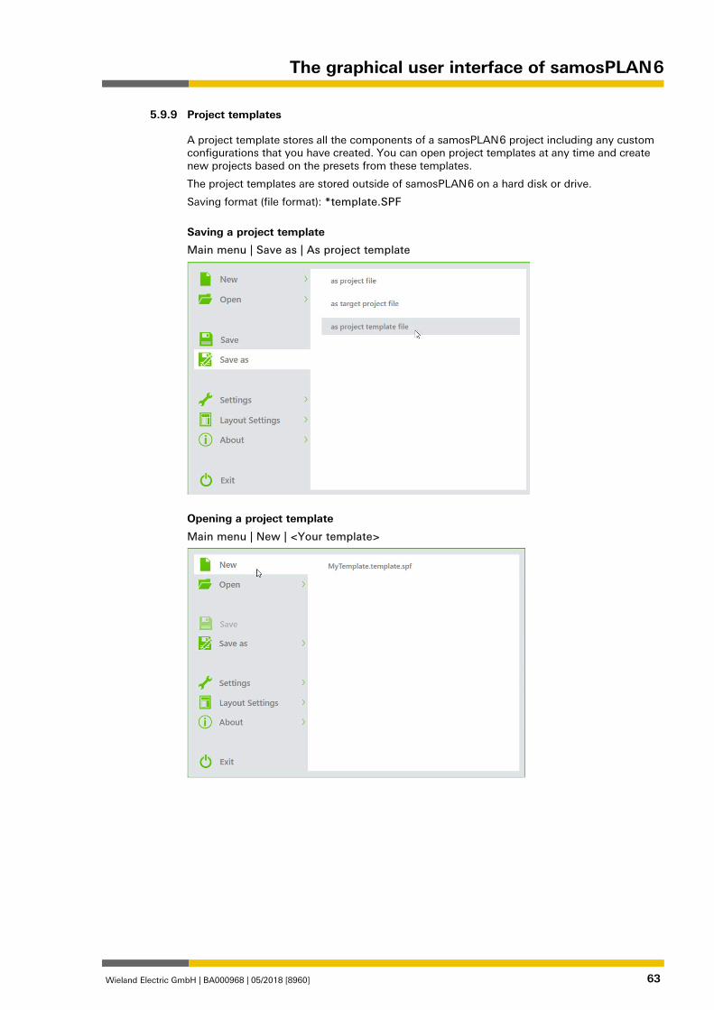
The graphical user interface of samosPLAN 6
Wieland Electric GmbH | BA000968 | 05/2018 [8960] 63
Project templates 1377334923
A project template stores all the components of a samosPLAN 6 project including any custom configurations that you have created. You can open project templates at any time and create new projects based on the presets from these templates.
The project templates are stored outside of samosPLAN 6 on a hard disk or drive.
Saving format (file format): *template.SPF
Saving a project template
Main menu | Save as | As project template
Opening a project template
Main menu | New | <Your template>
5.9.9
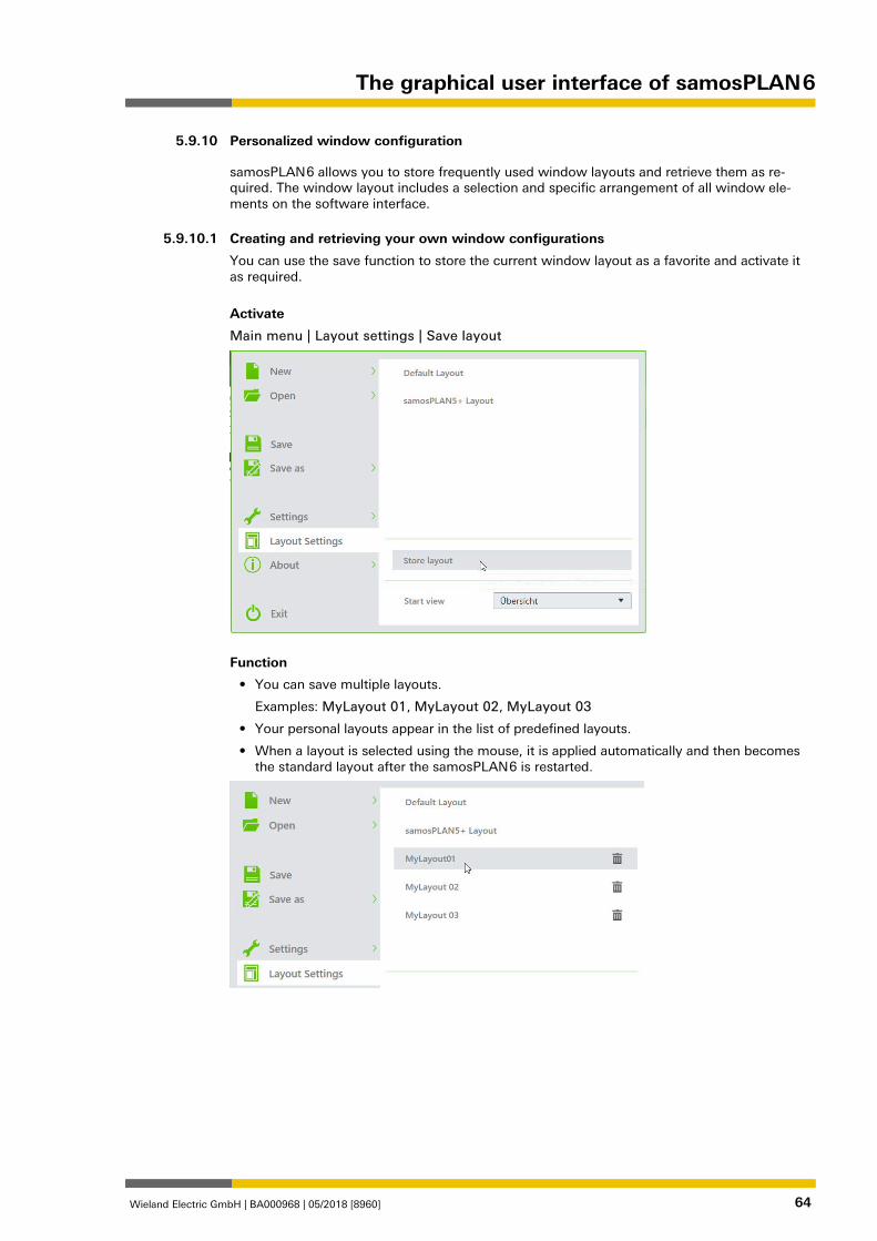
The graphical user interface of samosPLAN 6
Wieland Electric GmbH | BA000968 | 05/2018 [8960] 64
Personalized window configuration 1285961483
samosPLAN 6 allows you to store frequently used window layouts and retrieve them as re-quired. The window layout includes a selection and specific arrangement of all window ele-ments on the software interface. 1379456011
Creating and retrieving your own window configurations
You can use the save function to store the current window layout as a favorite and activate it as required.
Activate
Main menu | Layout settings | Save layout
Function
• You can save multiple layouts.
Examples: MyLayout 01, MyLayout 02, MyLayout 03
• Your personal layouts appear in the list of predefined layouts.
• When a layout is selected using the mouse, it is applied automatically and then becomes the standard layout after the samosPLAN 6 is restarted.
1379528715
5.9.10
5.9.10.1
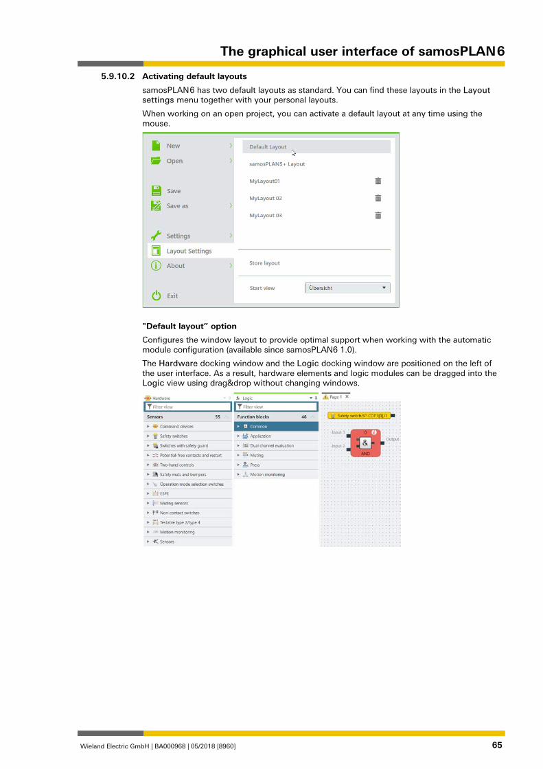
The graphical user interface of samosPLAN 6
Wieland Electric GmbH | BA000968 | 05/2018 [8960] 65
Activating default layouts
samosPLAN 6 has two default layouts as standard. You can find these layouts in the Layout settings menu together with your personal layouts.
When working on an open project, you can activate a default layout at any time using the mouse.
"Default layout” option
Configures the window layout to provide optimal support when working with the automatic module configuration (available since samosPLAN6 1.0).
The Hardware docking window and the Logic docking window are positioned on the left of the user interface. As a result, hardware elements and logic modules can be dragged into the Logic view using drag&drop without changing windows.
5.9.10.2
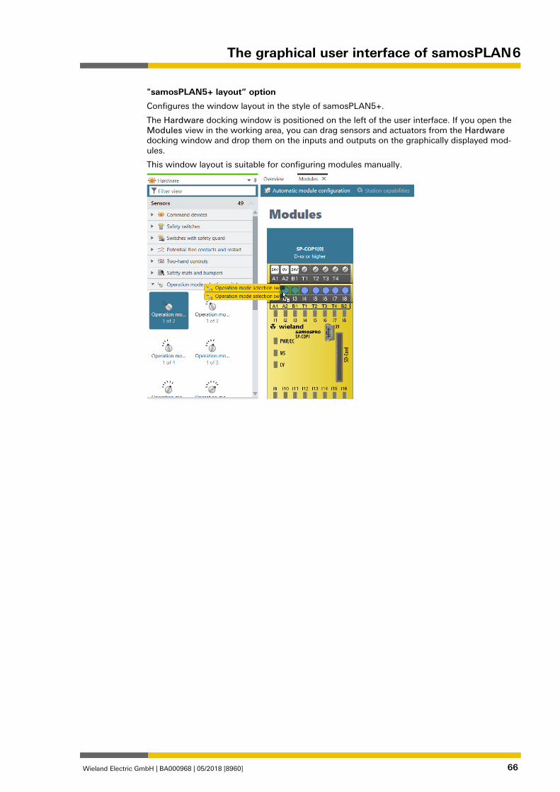
The graphical user interface of samosPLAN 6
Wieland Electric GmbH | BA000968 | 05/2018 [8960] 66
"samosPLAN5+ layout” option
Configures the window layout in the style of samosPLAN5+.
The Hardware docking window is positioned on the left of the user interface. If you open the Modules view in the working area, you can drag sensors and actuators from the Hardware docking window and drop them on the inputs and outputs on the graphically displayed mod-ules.
This window layout is suitable for configuring modules manually.
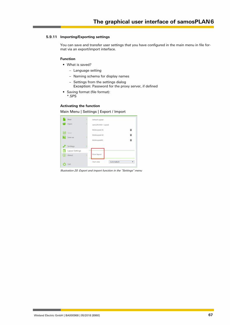
The graphical user interface of samosPLAN 6
Wieland Electric GmbH | BA000968 | 05/2018 [8960] 67
Importing/Exporting settings 862903179
You can save and transfer user settings that you have configured in the main menu in file for-mat via an export/import interface.
Function
• What is saved?
– Language setting
– Naming schema for display names
– Settings from the settings dialog Exception: Password for the proxy server, if defined
• Saving format (file format): *.SPS
Activating the function
Main Menu | Settings | Export / Import
Illustration 20: Export and import function in the "Settings" menu
5.9.11
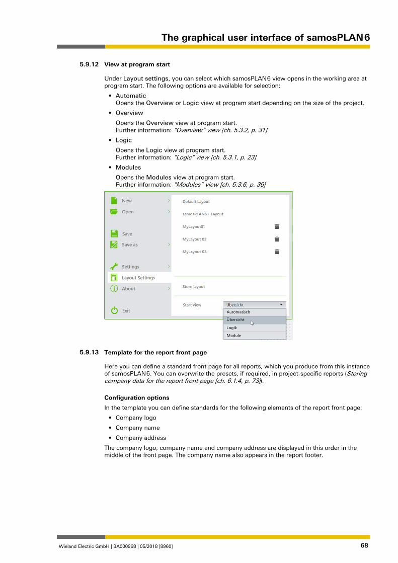
The graphical user interface of samosPLAN 6
Wieland Electric GmbH | BA000968 | 05/2018 [8960] 68
View at program start 1379700875
Under Layout settings, you can select which samosPLAN 6 view opens in the working area at program start. The following options are available for selection:
• Automatic Opens the Overview or Logic view at program start depending on the size of the project.
• Overview
Opens the Overview view at program start. Further information: "Overview" view [ch. 5.3.2, p. 31]
• Logic
Opens the Logic view at program start. Further information: "Logic" view [ch. 5.3.1, p. 23]
• Modules
Opens the Modules view at program start. Further information: "Modules” view [ch. 5.3.6, p. 36]
Template for the report front page 954846987
Here you can define a standard front page for all reports, which you produce from this instance of samosPLAN 6. You can overwrite the presets, if required, in project-specific reports (Storing company data for the report front page [ch. 6.1.4, p. 73]).
Configuration options
In the template you can define standards for the following elements of the report front page:
• Company logo
• Company name
• Company address
The company logo, company name and company address are displayed in this order in the middle of the front page. The company name also appears in the report footer.
5.9.12
5.9.13
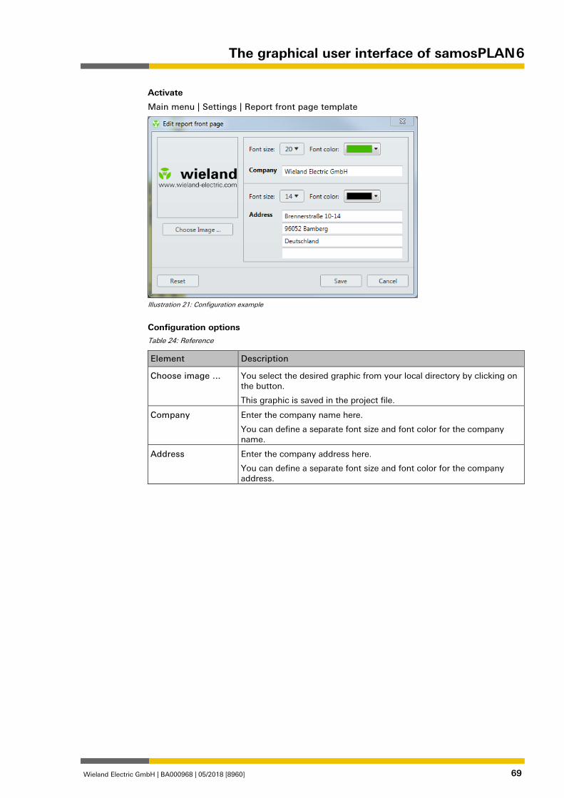
The graphical user interface of samosPLAN 6
Wieland Electric GmbH | BA000968 | 05/2018 [8960] 69
Activate
Main menu | Settings | Report front page template
Illustration 21: Configuration example
Configuration options Table 24: Reference
Element Description
Choose image ... You select the desired graphic from your local directory by clicking on the button.
This graphic is saved in the project file.
Company Enter the company name here.
You can define a separate font size and font color for the company name.
Address Enter the company address here.
You can define a separate font size and font color for the company address.

Working with samosPLAN 6
Wieland Electric GmbH | BA000968 | 05/2018 [8960] 70
Working with samosPLAN 6 1276680331
What do you typically do, and in what sequence when you work with samosPLAN 6?
This chapter offers guidelines to guide you through all the important work steps - starting with the creation of a new project through to monitoring a ready-programmed control when run-ning.
Setting up a project 1278446475
Up to the cross-project settings [ch. 5.9, p. 55] everything relates to what you do in sa-mosPLAN 6 on the project which is open at that particular time.
How do you create a project? And what kind of objects can you set and configure for a pro-ject?
Creating a new project 862910475
When you start samosPLAN 6, you can create a new empty project in the start view using the New project button.
If samosPLAN 6 is already open, you can create a new project by clicking on New in the sa-mosPLAN 6 menu.
NOTICE Tip: Using project templates If you frequently need to use certain configurations in new projects, you can create project templates. These also appear in the samosPLAN 6 start view. Further information: Project templates [ch. 5.9.9, p. 63]
Program behavior
In the case of a new project in samosPLAN 6, either the Overview, Logic or Modules view is displayed in the working area, depending on your presets (see View at program start [ch. 5.9.12, p. 68]). Only these three views are active, unless otherwise configured in a project.
6
6.1
6.1.1
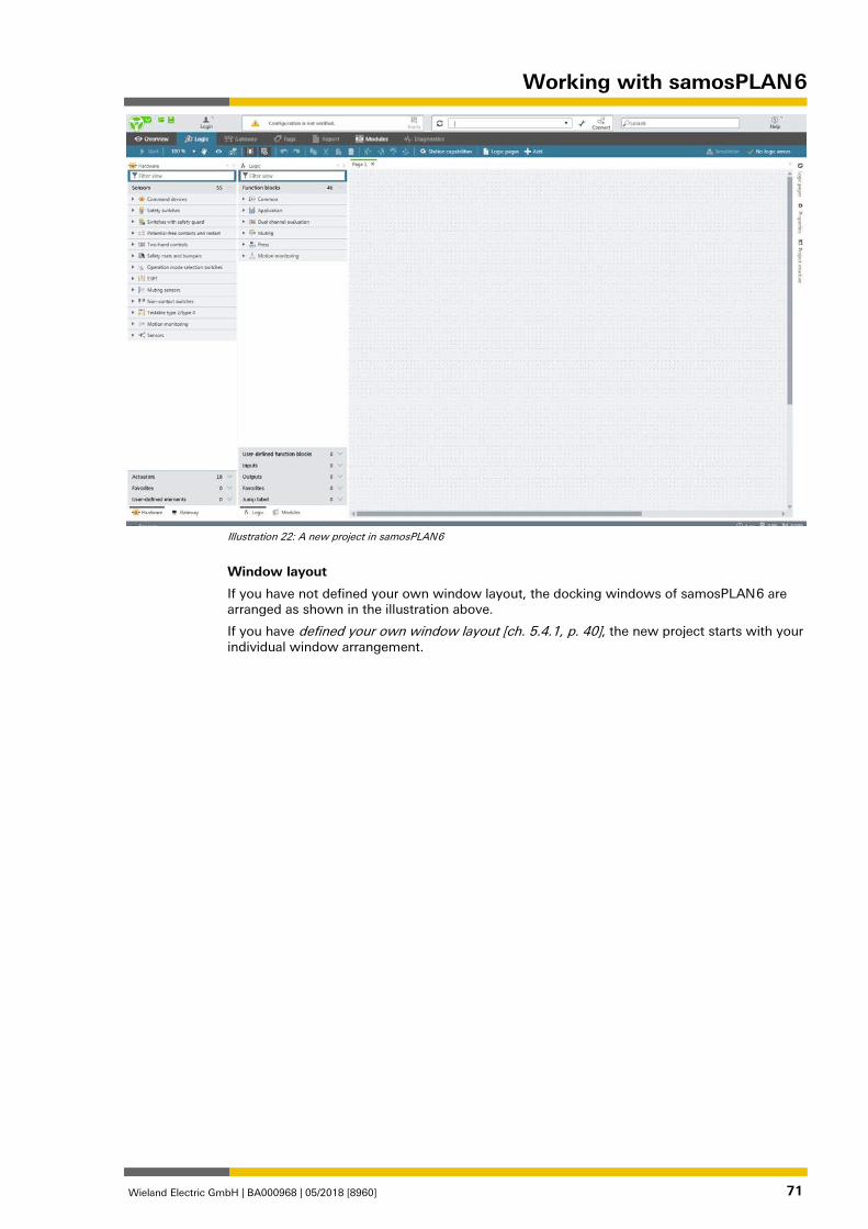
Working with samosPLAN 6
Wieland Electric GmbH | BA000968 | 05/2018 [8960] 71
Illustration 22: A new project in samosPLAN 6
Window layout
If you have not defined your own window layout, the docking windows of samosPLAN 6 are arranged as shown in the illustration above.
If you have defined your own window layout [ch. 5.4.1, p. 40], the new project starts with your individual window arrangement.
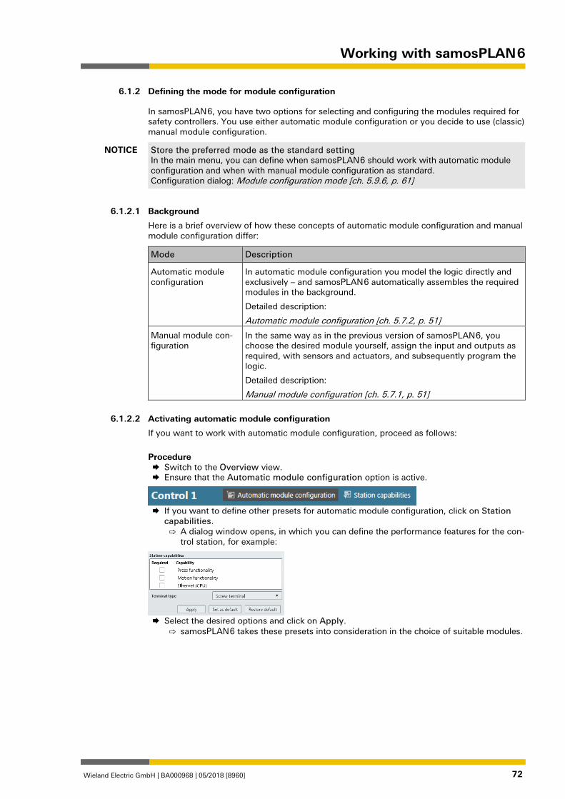
Working with samosPLAN 6
Wieland Electric GmbH | BA000968 | 05/2018 [8960] 72
Defining the mode for module configuration 1279507339
In samosPLAN 6, you have two options for selecting and configuring the modules required for safety controllers. You use either automatic module configuration or you decide to use (classic) manual module configuration.
NOTICE Store the preferred mode as the standard setting In the main menu, you can define when samosPLAN 6 should work with automatic module configuration and when with manual module configuration as standard. Configuration dialog: Module configuration mode [ch. 5.9.6, p. 61]
1280232331
Background
Here is a brief overview of how these concepts of automatic module configuration and manual module configuration differ:
Mode Description
Automatic module configuration
In automatic module configuration you model the logic directly and exclusively – and samosPLAN 6 automatically assembles the required modules in the background.
Detailed description:
Automatic module configuration [ch. 5.7.2, p. 51]
Manual module con-figuration
In the same way as in the previous version of samosPLAN 6, you choose the desired module yourself, assign the input and outputs as required, with sensors and actuators, and subsequently program the logic.
Detailed description:
Manual module configuration [ch. 5.7.1, p. 51]
1280234507
Activating automatic module configuration
If you want to work with automatic module configuration, proceed as follows:
Procedure Switch to the Overview view. Ensure that the Automatic module configuration option is active.
If you want to define other presets for automatic module configuration, click on Station
capabilities. ⇨ A dialog window opens, in which you can define the performance features for the con-
trol station, for example:
Select the desired options and click on Apply.
⇨ samosPLAN 6 takes these presets into consideration in the choice of suitable modules. 1280236043
6.1.2
6.1.2.1
6.1.2.2
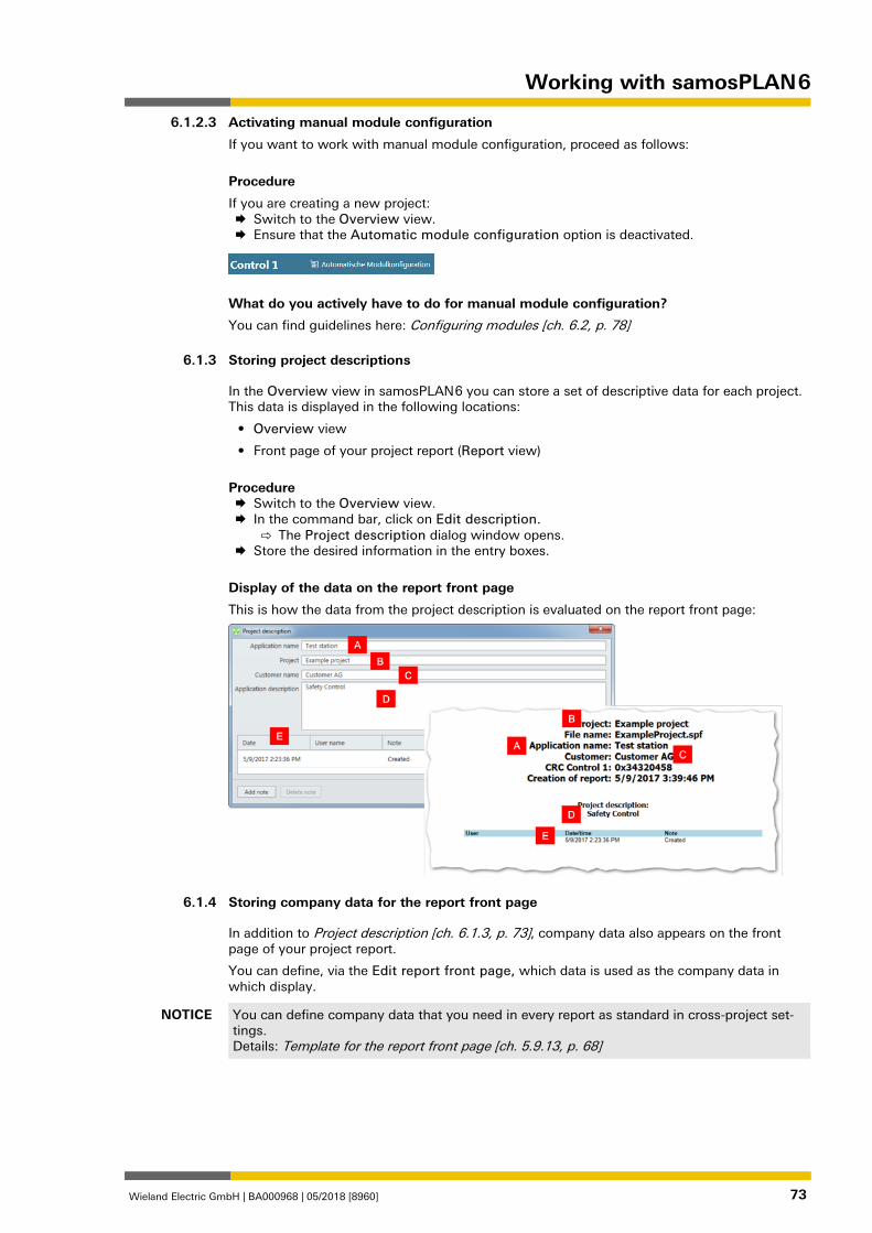
Working with samosPLAN 6
Wieland Electric GmbH | BA000968 | 05/2018 [8960] 73
Activating manual module configuration
If you want to work with manual module configuration, proceed as follows:
Procedure
If you are creating a new project: Switch to the Overview view. Ensure that the Automatic module configuration option is deactivated.
What do you actively have to do for manual module configuration?
You can find guidelines here: Configuring modules [ch. 6.2, p. 78]
Storing project descriptions 1280127883
In the Overview view in samosPLAN 6 you can store a set of descriptive data for each project. This data is displayed in the following locations:
• Overview view
• Front page of your project report (Report view)
Procedure Switch to the Overview view. In the command bar, click on Edit description.
⇨ The Project description dialog window opens. Store the desired information in the entry boxes.
Display of the data on the report front page
This is how the data from the project description is evaluated on the report front page:
Storing company data for the report front page 1278848523
In addition to Project description [ch. 6.1.3, p. 73], company data also appears on the front page of your project report.
You can define, via the Edit report front page, which data is used as the company data in which display.
NOTICE You can define company data that you need in every report as standard in cross-project set-tings. Details: Template for the report front page [ch. 5.9.13, p. 68]
6.1.2.3
6.1.3
6.1.4
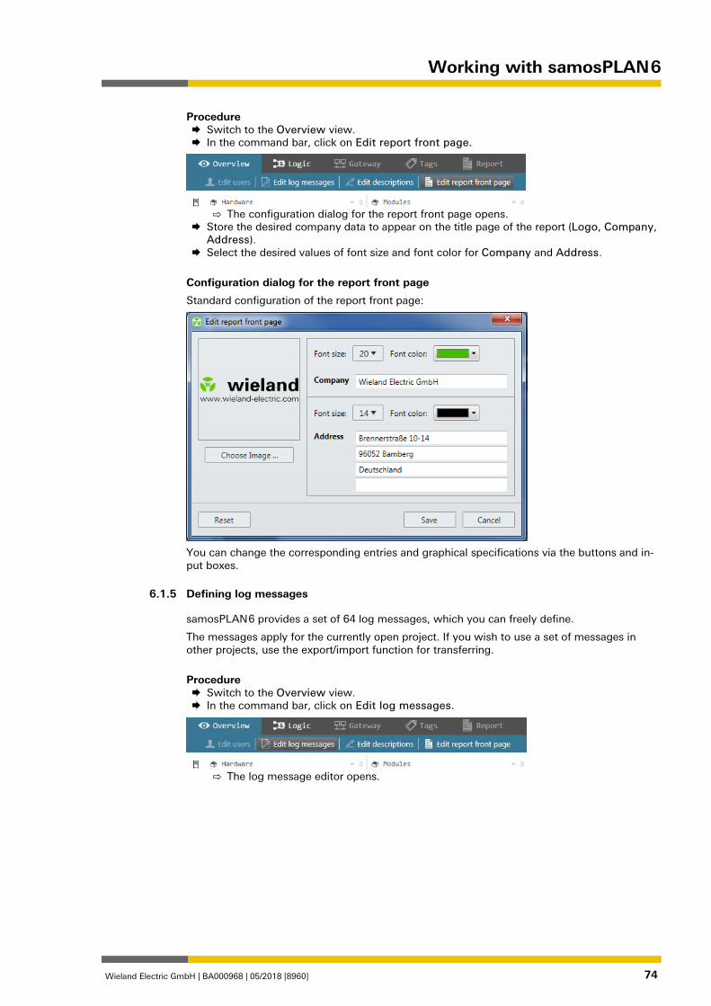
Working with samosPLAN 6
Wieland Electric GmbH | BA000968 | 05/2018 [8960] 74
Procedure Switch to the Overview view. In the command bar, click on Edit report front page.
⇨ The configuration dialog for the report front page opens.
Store the desired company data to appear on the title page of the report (Logo, Company, Address).
Select the desired values of font size and font color for Company and Address.
Configuration dialog for the report front page
Standard configuration of the report front page:
You can change the corresponding entries and graphical specifications via the buttons and in-put boxes.
Defining log messages 862912011
samosPLAN 6 provides a set of 64 log messages, which you can freely define.
The messages apply for the currently open project. If you wish to use a set of messages in other projects, use the export/import function for transferring.
Procedure Switch to the Overview view. In the command bar, click on Edit log messages.
⇨ The log message editor opens.
6.1.5
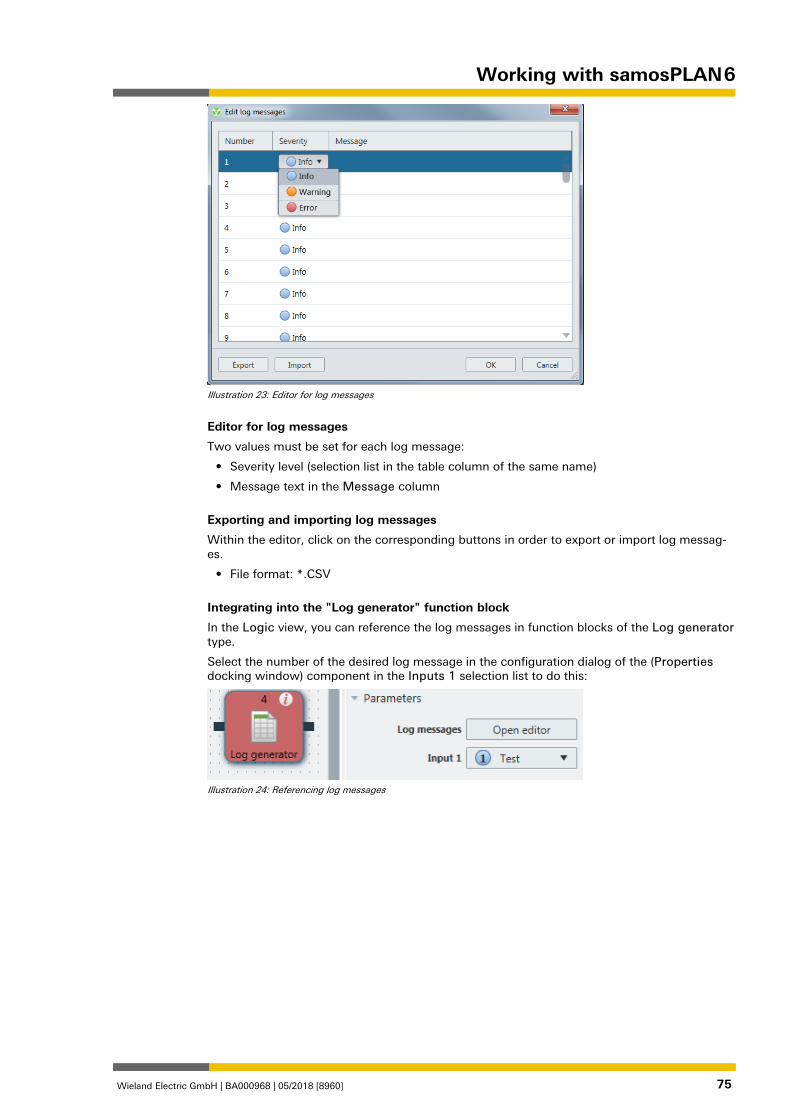
Working with samosPLAN 6
Wieland Electric GmbH | BA000968 | 05/2018 [8960] 75
Illustration 23: Editor for log messages
Editor for log messages
Two values must be set for each log message:
• Severity level (selection list in the table column of the same name)
• Message text in the Message column
Exporting and importing log messages
Within the editor, click on the corresponding buttons in order to export or import log messag-es.
• File format: *.CSV
Integrating into the "Log generator" function block
In the Logic view, you can reference the log messages in function blocks of the Log generator type.
Select the number of the desired log message in the configuration dialog of the (Properties docking window) component in the Inputs 1 selection list to do this:
Illustration 24: Referencing log messages
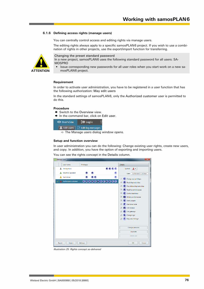
Working with samosPLAN 6
Wieland Electric GmbH | BA000968 | 05/2018 [8960] 76
Defining access rights (manage users) 862916363
You can centrally control access and editing rights via manage users.
The editing rights always apply to a specific samosPLAN 6 project. If you wish to use a combi-nation of rights in other projects, use the export/import function for transferring.
ATTENTION
Changing the preset standard password In a new project, samosPLAN 6 uses the following standard password for all users: SA-MOSPRO • Issue corresponding new passwords for all user roles when you start work on a new sa-
mosPLAN 6 project.
Requirement
In order to activate user administration, you have to be registered in a user function that has the following authorization: May edit users
In the standard settings of samosPLAN 6, only the Authorized customer user is permitted to do this.
Procedure Switch to the Overview view. In the command bar, click on Edit user.
⇨ The Manage users dialog window opens.
Setup and function overview
In user administration you can do the following: Change existing user rights, create new users, and copy. In addition, you have the option of exporting and importing users.
You can see the rights concept in the Details column.
Illustration 25: Rights concept as-delivered
6.1.6
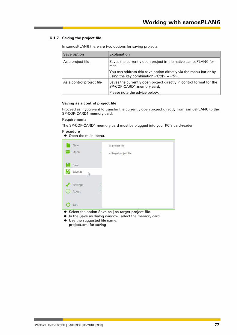
Working with samosPLAN 6
Wieland Electric GmbH | BA000968 | 05/2018 [8960] 77
Saving the project file 1177505419
In samosPLAN 6 there are two options for saving projects:
Save option Explanation
As a project file Saves the currently open project in the native samosPLAN 6 for-mat.
You can address this save option directly via the menu bar or by using the key combination <Ctrl> + <S>.
As a control project file Saves the currently open project directly in control format for the SP-COP-CARD1 memory card.
Please note the advice below.
Saving as a control project file
Proceed as if you want to transfer the currently open project directly from samosPLAN 6 to the SP-COP-CARD1 memory card:
Requirements
The SP-COP-CARD1 memory card must be plugged into your PC’s card-reader.
Procedure Open the main menu.
Select the option Save as | as target project file. In the Save as dialog window, select the memory card. Use the suggested file name:
project.xml for saving
6.1.7
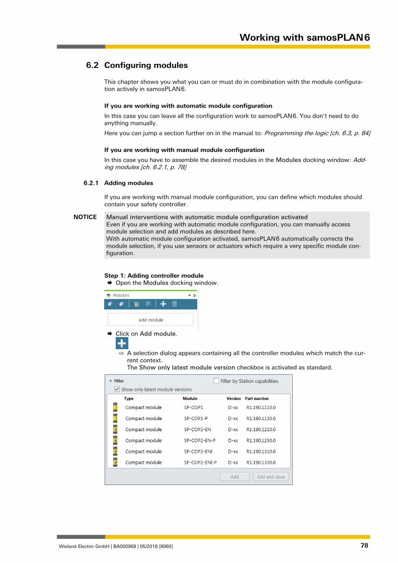
Working with samosPLAN 6
Wieland Electric GmbH | BA000968 | 05/2018 [8960] 78
Configuring modules 1280321931
This chapter shows you what you can or must do in combination with the module configura-tion actively in samosPLAN 6.
If you are working with automatic module configuration
In this case you can leave all the configuration work to samosPLAN 6. You don’t need to do anything manually.
Here you can jump a section further on in the manual to: Programming the logic [ch. 6.3, p. 84]
If you are working with manual module configuration
In this case you have to assemble the desired modules in the Modules docking window: Add-ing modules [ch. 6.2.1, p. 78]
Adding modules 862926603
If you are working with manual module configuration, you can define which modules should contain your safety controller.
NOTICE Manual interventions with automatic module configuration activated Even if you are working with automatic module configuration, you can manually access module selection and add modules as described here. With automatic module configuration activated, samosPLAN 6 automatically corrects the module selection, if you use sensors or actuators which require a very specific module con-figuration.
Step 1: Adding controller module Open the Modules docking window.
Click on Add module.
⇨ A selection dialog appears containing all the controller modules which match the cur-
rent context. The Show only latest module version checkbox is activated as standard.
6.2
6.2.1
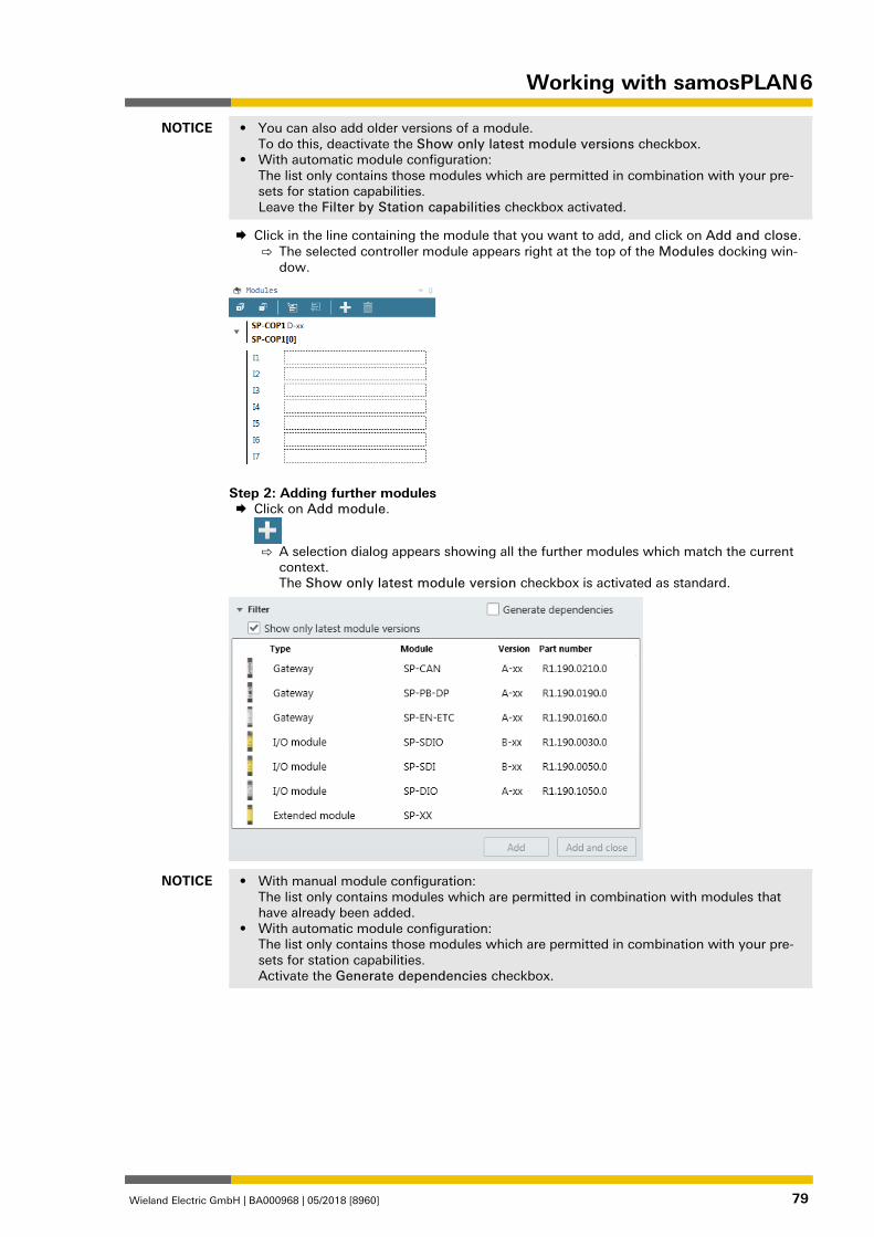
Working with samosPLAN 6
Wieland Electric GmbH | BA000968 | 05/2018 [8960] 79
NOTICE • You can also add older versions of a module. To do this, deactivate the Show only latest module versions checkbox.
• With automatic module configuration: The list only contains those modules which are permitted in combination with your pre-sets for station capabilities. Leave the Filter by Station capabilities checkbox activated.
Click in the line containing the module that you want to add, and click on Add and close. ⇨ The selected controller module appears right at the top of the Modules docking win-
dow.
Step 2: Adding further modules Click on Add module.
⇨ A selection dialog appears showing all the further modules which match the current
context. The Show only latest module version checkbox is activated as standard.
NOTICE • With manual module configuration: The list only contains modules which are permitted in combination with modules that have already been added.
• With automatic module configuration: The list only contains those modules which are permitted in combination with your pre-sets for station capabilities. Activate the Generate dependencies checkbox.
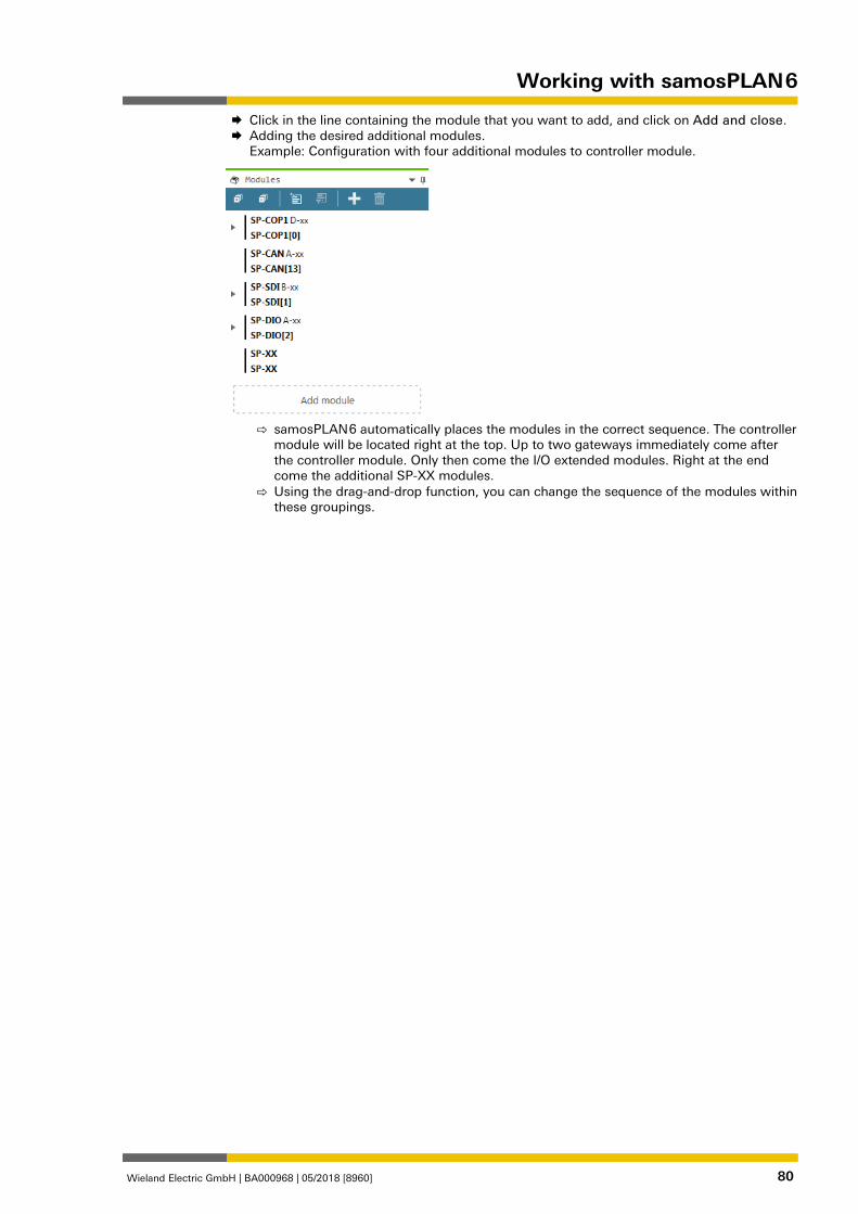
Working with samosPLAN 6
Wieland Electric GmbH | BA000968 | 05/2018 [8960] 80
Click in the line containing the module that you want to add, and click on Add and close. Adding the desired additional modules.
Example: Configuration with four additional modules to controller module.
⇨ samosPLAN 6 automatically places the modules in the correct sequence. The controller
module will be located right at the top. Up to two gateways immediately come after the controller module. Only then come the I/O extended modules. Right at the end come the additional SP-XX modules.
⇨ Using the drag-and-drop function, you can change the sequence of the modules within these groupings.
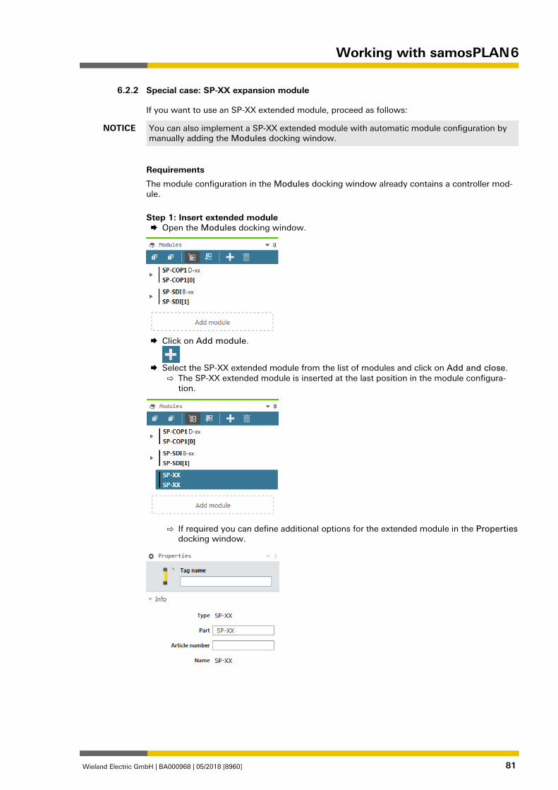
Working with samosPLAN 6
Wieland Electric GmbH | BA000968 | 05/2018 [8960] 81
Special case: SP-XX expansion module 1127073547
If you want to use an SP-XX extended module, proceed as follows:
NOTICE You can also implement a SP-XX extended module with automatic module configuration by manually adding the Modules docking window.
Requirements
The module configuration in the Modules docking window already contains a controller mod-ule.
Step 1: Insert extended module Open the Modules docking window.
Click on Add module.
Select the SP-XX extended module from the list of modules and click on Add and close.
⇨ The SP-XX extended module is inserted at the last position in the module configura-tion.
⇨ If required you can define additional options for the extended module in the Properties
docking window.
6.2.2
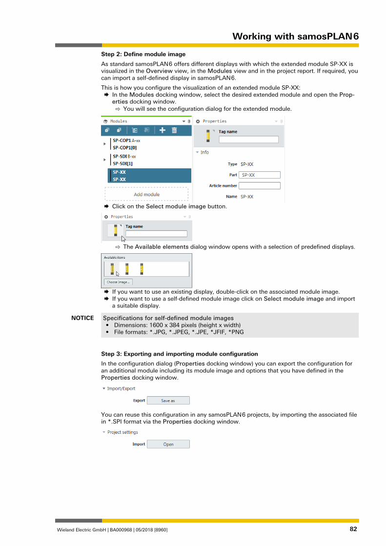
Working with samosPLAN 6
Wieland Electric GmbH | BA000968 | 05/2018 [8960] 82
Step 2: Define module image
As standard samosPLAN 6 offers different displays with which the extended module SP-XX is visualized in the Overview view, in the Modules view and in the project report. If required, you can import a self-defined display in samosPLAN 6.
This is how you configure the visualization of an extended module SP-XX: In the Modules docking window, select the desired extended module and open the Prop-
erties docking window. ⇨ You will see the configuration dialog for the extended module.
Click on the Select module image button.
⇨ The Available elements dialog window opens with a selection of predefined displays.
If you want to use an existing display, double-click on the associated module image. If you want to use a self-defined module image click on Select module image and import
a suitable display.
NOTICE Specifications for self-defined module images • Dimensions: 1600 x 384 pixels (height x width) • File formats: *.JPG, *.JPEG, *.JPE, *JFIF, *PNG
Step 3: Exporting and importing module configuration
In the configuration dialog (Properties docking window) you can export the configuration for an additional module including its module image and options that you have defined in the Properties docking window.
You can reuse this configuration in any samosPLAN 6 projects, by importing the associated file in *.SPI format via the Properties docking window.
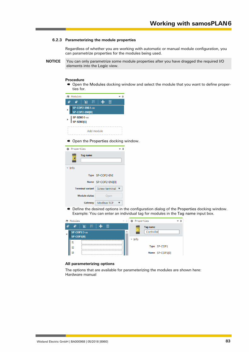
Working with samosPLAN 6
Wieland Electric GmbH | BA000968 | 05/2018 [8960] 83
Parameterizing the module properties 1280327947
Regardless of whether you are working with automatic or manual module configuration, you can parametrize properties for the modules being used.
NOTICE You can only parametrize some module properties after you have dragged the required I/O elements into the Logic view.
Procedure Open the Modules docking window and select the module that you want to define proper-
ties for.
Open the Properties docking window.
Define the desired options in the configuration dialog of the Properties docking window.
Example: You can enter an individual tag for modules in the Tag name input box.
All parameterizing options
The options that are available for parameterizing the modules are shown here: Hardware manual
6.2.3
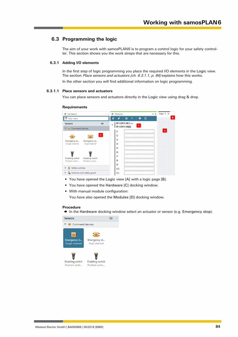
Working with samosPLAN 6
Wieland Electric GmbH | BA000968 | 05/2018 [8960] 84
Programming the logic 1278745227
The aim of your work with samosPLAN 6 is to program a control logic for your safety control-ler. This section shows you the work streps that are necessary for this.
Adding I/O elements 1278815755
In the first step of logic programming you place the required I/O elements in the Logic view. The section Place sensors and actuators [ch. 6.3.1.1, p. 84] explains how this works.
In the other section you will find additional information on logic programming. 862927627
Place sensors and actuators
You can place sensors and actuators directly in the Logic view using drag & drop.
Requirements
• You have opened the Logic view [A] with a logic page [B].
• You have opened the Hardware [C] docking window.
• With manual module configuration:
You have also opened the Modules [D] docking window.
Procedure In the Hardware docking window select an actuator or sensor (e.g. Emergency stop).
6.3
6.3.1
6.3.1.1
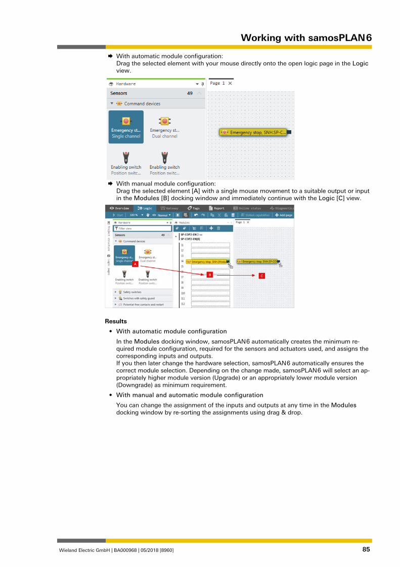
Working with samosPLAN 6
Wieland Electric GmbH | BA000968 | 05/2018 [8960] 85
With automatic module configuration: Drag the selected element with your mouse directly onto the open logic page in the Logic view.
With manual module configuration:
Drag the selected element [A] with a single mouse movement to a suitable output or input in the Modules [B] docking window and immediately continue with the Logic [C] view.
Results
• With automatic module configuration
In the Modules docking window, samosPLAN 6 automatically creates the minimum re-quired module configuration, required for the sensors and actuators used, and assigns the corresponding inputs and outputs. If you then later change the hardware selection, samosPLAN 6 automatically ensures the correct module selection. Depending on the change made, samosPLAN 6 will select an ap-propriately higher module version (Upgrade) or an appropriately lower module version (Downgrade) as minimum requirement.
• With manual and automatic module configuration
You can change the assignment of the inputs and outputs at any time in the Modules docking window by re-sorting the assignments using drag & drop.
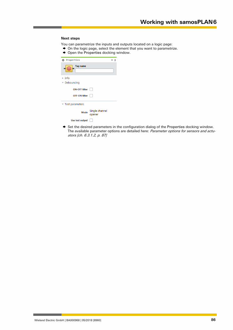
Working with samosPLAN 6
Wieland Electric GmbH | BA000968 | 05/2018 [8960] 86
Next steps
You can parametrize the inputs and outputs located on a logic page: On the logic page, select the element that you want to parametrize. Open the Properties docking window.
Set the desired parameters in the configuration dialog of the Properties docking window.
The available parameter options are detailed here: Parameter options for sensors and actu-ators [ch. 6.3.1.2, p. 87]
Working with samosPLAN 6
Wieland Electric GmbH | BA000968 | 05/2018 [8960] 87
862931979
Parameter options for sensors and actuators
The following parameters are available for sensors and actuators. Depending on the type of el-ement, they will vary in scope and selection:
Tag name
If you do not assign your own tag name, the default tag name will be used.
Synchronous time
Two-channel elements can be selected with or without synchronous time. Synchronous time determines how long the two inputs will be allowed to have discrepant values after one of the two input signals has changed its value without this being evaluated as an error.
Detailed information on synchronous time monitoring by the I/O modules: Two-channel evalua-tion and synchronous time [ch. 6.3.1.2.1, p. 90]
Procedure Enter a value between 0 and 30000.
Info
For elements which are connected to modules of the SP-SDI or SP-SDIO class, the following limitations apply:
The value for synchronous time can be set to 0 = deactivated or to a value of 4 ms to 30 s. Due to the internal evaluation frequency of the modules, the value is automatically rounded up to the next-higher multiple of 4 ms.
If signals of tested sensors are connected to modules of the SP-SDI or SP-SDIO class, the syn-chronous time must be greater than the test gap + the max. OFF-ON delay of the test output used. You can find these values in the project report under Configuration, I/O module, Test pulse parameter.
If you attempt to set a synchronous time that is less than permitted, the minimum value will be displayed in the dialog window.
On-Off filter or Off-On filter
Upon the opening or closing of a contact-based component, multiple short signal changes will undesirably result due to the bounce of the contacts. Because this can influence the evaluation of the input, you can use the On-Off filter for falling edges (i.e., transitions from high to low) and the Off-On filter for rising edges (i.e., transitions from low to high) in order to eliminate this effect.
Procedure Activate or deactivate the corresponding checkboxes.
Info
• Once the On-Off filter or the Off-On filter is active, then a change in the signal is only rec-ognized as such when it is confirmed by three identical evaluations of the input directly af-ter one another with an evaluation frequency of 4 ms, i.e. when the signal is constantly present for 8-12 ms.
• When there are two-channel elements with a discrepancy evaluation, the respective filter (On-Off or Off-On) always relates to the lead channel. The filter for the complementary channel is automatically active.
ATTENTION
Be aware of the extended response times if you use the input filter! • Due to the internal evaluation frequency of the modules of 4 ms, the On-Off filter and the
Off-On filter will extend the response time by at least 8 ms. • If the signal changes within this initial 8 ms, then the signal change can be delayed signif-
icantly longer, i.e. until a constant signal of at least 8 ms has been detected.
6.3.1.2
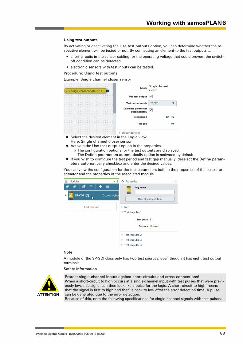
Working with samosPLAN 6
Wieland Electric GmbH | BA000968 | 05/2018 [8960] 88
Using test outputs
By activating or deactivating the Use test outputs option, you can determine whether the re-spective element will be tested or not. By connecting an element to the test outputs ...
• short-circuits in the sensor cabling for the operating voltage that could prevent the switch-off condition can be detected
• electronic sensors with test inputs can be tested.
Procedure: Using test outputs
Example: Single channel closer sensor
Select the desired element in the Logic view.
Here: Single channel closer sensor Activate the Use test output option in the properties.
⇨ The configuration options for the test outputs are displayed. The Define parameters automatically option is activated by default.
If you wish to configure the test period and test gap manually, deselect the Define param-eters automatically checkbox and enter the desired values.
You can view the configuration for the test parameters both in the properties of the sensor or actuator and the properties of the associated module.
Note
A module of the SP-SDI class only has two test sources, even though it has eight test output terminals.
Safety information
ATTENTION
Protect single-channel inputs against short-circuits and cross-connections! When a short-circuit to high occurs at a single-channel input with test pulses that were previ-ously low, this signal can then look like a pulse for the logic. A short-circuit to high means that the signal is first to high and then is back to low after the error detection time. A pulse can be generated due to the error detection. Because of this, note the following specifications for single-channel signals with test pulses:
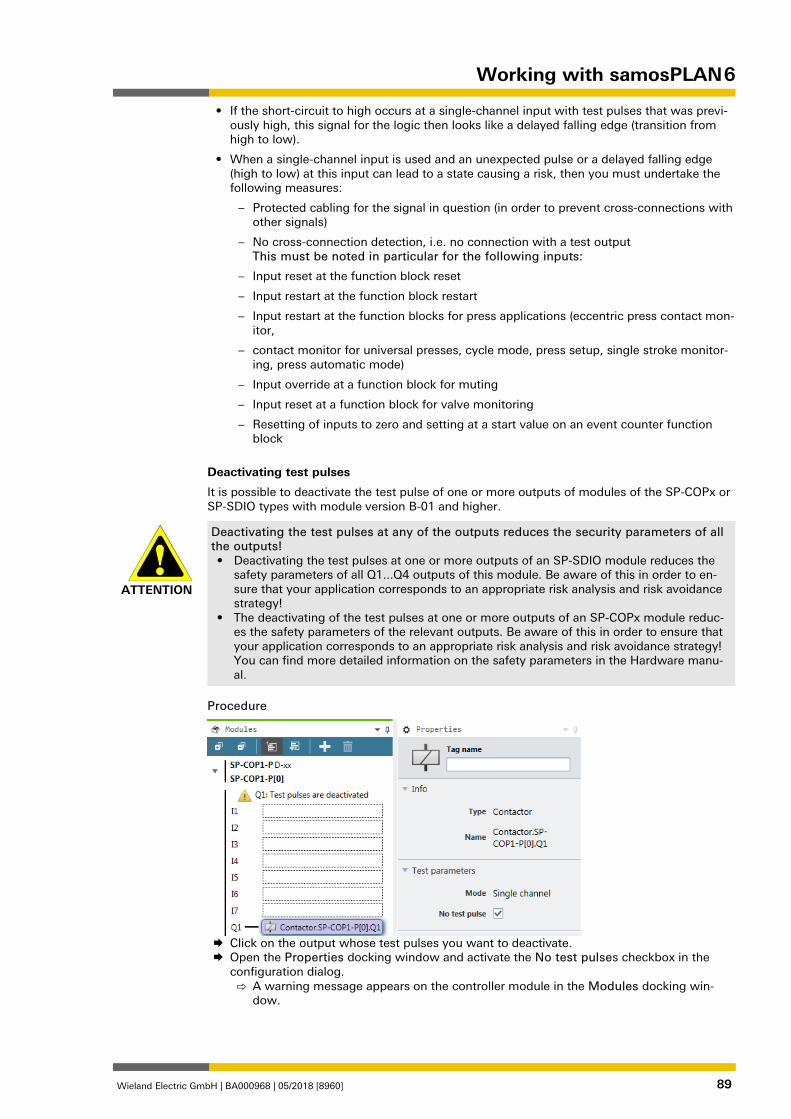
Working with samosPLAN 6
Wieland Electric GmbH | BA000968 | 05/2018 [8960] 89
• If the short-circuit to high occurs at a single-channel input with test pulses that was previ-ously high, this signal for the logic then looks like a delayed falling edge (transition from high to low).
• When a single-channel input is used and an unexpected pulse or a delayed falling edge (high to low) at this input can lead to a state causing a risk, then you must undertake the following measures:
– Protected cabling for the signal in question (in order to prevent cross-connections with other signals)
– No cross-connection detection, i.e. no connection with a test output This must be noted in particular for the following inputs:
– Input reset at the function block reset
– Input restart at the function block restart
– Input restart at the function blocks for press applications (eccentric press contact mon-itor,
– contact monitor for universal presses, cycle mode, press setup, single stroke monitor-ing, press automatic mode)
– Input override at a function block for muting
– Input reset at a function block for valve monitoring
– Resetting of inputs to zero and setting at a start value on an event counter function block
Deactivating test pulses
It is possible to deactivate the test pulse of one or more outputs of modules of the SP-COPx or SP-SDIO types with module version B-01 and higher.
ATTENTION
Deactivating the test pulses at any of the outputs reduces the security parameters of all the outputs! • Deactivating the test pulses at one or more outputs of an SP-SDIO module reduces the
safety parameters of all Q1...Q4 outputs of this module. Be aware of this in order to en-sure that your application corresponds to an appropriate risk analysis and risk avoidance strategy!
• The deactivating of the test pulses at one or more outputs of an SP-COPx module reduc-es the safety parameters of the relevant outputs. Be aware of this in order to ensure that your application corresponds to an appropriate risk analysis and risk avoidance strategy! You can find more detailed information on the safety parameters in the Hardware manu-al.
Procedure
Click on the output whose test pulses you want to deactivate. Open the Properties docking window and activate the No test pulses checkbox in the
configuration dialog. ⇨ A warning message appears on the controller module in the Modules docking win-
dow. 840251659
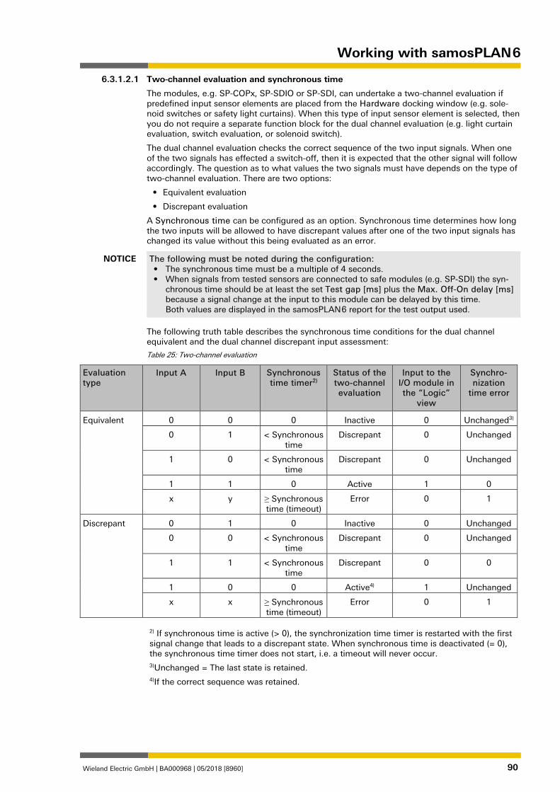
Working with samosPLAN 6
Wieland Electric GmbH | BA000968 | 05/2018 [8960] 90
Two-channel evaluation and synchronous time
The modules, e.g. SP-COPx, SP-SDIO or SP-SDI, can undertake a two-channel evaluation if predefined input sensor elements are placed from the Hardware docking window (e.g. sole-noid switches or safety light curtains). When this type of input sensor element is selected, then you do not require a separate function block for the dual channel evaluation (e.g. light curtain evaluation, switch evaluation, or solenoid switch).
The dual channel evaluation checks the correct sequence of the two input signals. When one of the two signals has effected a switch-off, then it is expected that the other signal will follow accordingly. The question as to what values the two signals must have depends on the type of two-channel evaluation. There are two options:
• Equivalent evaluation
• Discrepant evaluation
A Synchronous time can be configured as an option. Synchronous time determines how long the two inputs will be allowed to have discrepant values after one of the two input signals has changed its value without this being evaluated as an error.
NOTICE The following must be noted during the configuration: • The synchronous time must be a multiple of 4 seconds. • When signals from tested sensors are connected to safe modules (e.g. SP-SDI) the syn-
chronous time should be at least the set Test gap [ms] plus the Max. Off-On delay [ms] because a signal change at the input to this module can be delayed by this time. Both values are displayed in the samosPLAN 6 report for the test output used.
The following truth table describes the synchronous time conditions for the dual channel equivalent and the dual channel discrepant input assessment:
Table 25: Two-channel evaluation
Evaluation type
Input A Input B Synchronous time timer2)
Status of the two-channel evaluation
Input to the I/O module in the “Logic”
view
Synchro-nization
time error
Equivalent 0 0 0 Inactive 0 Unchanged3)
0 1 < Synchronous time
Discrepant 0 Unchanged
1 0 < Synchronous time
Discrepant 0 Unchanged
1 1 0 Active 1 0
x y ≥ Synchronous time (timeout)
Error 0 1
Discrepant 0 1 0 Inactive 0 Unchanged
0 0 < Synchronous time
Discrepant 0 Unchanged
1 1 < Synchronous time
Discrepant 0 0
1 0 0 Active4) 1 Unchanged
x x ≥ Synchronous time (timeout)
Error 0 1
2) If synchronous time is active (> 0), the synchronization time timer is restarted with the first signal change that leads to a discrepant state. When synchronous time is deactivated (= 0), the synchronous time timer does not start, i.e. a timeout will never occur. 3)Unchanged = The last state is retained. 4)If the correct sequence was retained.
6.3.1.2.1

Working with samosPLAN 6
Wieland Electric GmbH | BA000968 | 05/2018 [8960] 91
The following rules apply to the transitions between the various states of the two-channel evaluation:
A dual channel evaluation can only be active (the input of the I/O module in the Logic view changes from low to high) if ...
• The state since the last active was inactive at least once; i.e. it is not possible to switch from active to discrepant and back to active; and
• Synchronous time has not expired or is deactivated.
NOTICE If the correct sequence for reaching the active state has not been maintained (i.e. if the status has switched from active to discrepant to active), then modules of the SP-SDIO and SP-SDI class will indicate this sequence error within 100 ms at the latest if the synchronous time has not elapsed before this (i.e. if the synchronization time is set at 0 or to a value > 100 ms). Older modules will not show this sequence error; however, their input in the Logic view like-wise remains at low.
In the event of a synchronization time error or a sequence error, the module will behave as fol-lows:
• The MS LED for the respective module will flash red (1 Hz).
• The LEDs for the respective inputs will flash green (1 Hz).
• The Input data status of the module will be low in the Logic view.
Resetting the error:
A synchronous time error (timeout) or sequence error is reset when the inactive state was reached. 862967819
CPU flag
CPU flags are available as inputs and outputs in the Logic view. They can be used to create logical loopbacks, for example.
A CPU flag consists of an output flag and an input flag. The input flag always assumes the same value (high or low) as the corresponding output flag with a delay of a logic cycle (i.e. the logic execution time).
You can use input flags multiple times.
ATTENTION
Increased delay times can make the control unstable. CPU flags always cause a delay of 1x the logic execution time. The reason for this is that the input flags always assume the value that the output flag had in the previous logic cycle. • Always calculate the resulting delay when computing the response time and functionali-
ty.
862969355
Jump addresses
Jump addresses consist of a source jump address and a target jump address. The target jump address assumes the same value (high or low) as the corresponding source jump addressed without delay – provided it does not involve a loopback. In this respect, jump addresses differ from CPU flags.
You can use jump addresses in order to interconnect components that are on different logic pages.
You can use target jump addresses multiple times.
6.3.1.3
6.3.1.4
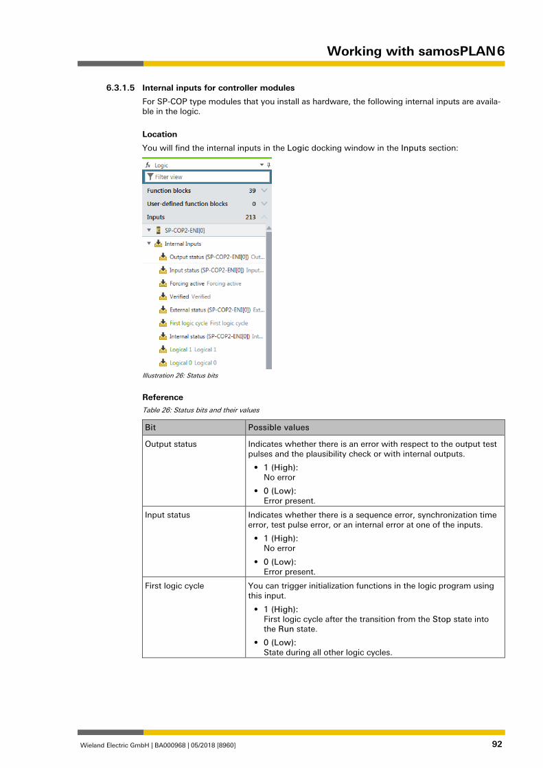
Working with samosPLAN 6
Wieland Electric GmbH | BA000968 | 05/2018 [8960] 92
862959115
Internal inputs for controller modules
For SP-COP type modules that you install as hardware, the following internal inputs are availa-ble in the logic.
Location
You will find the internal inputs in the Logic docking window in the Inputs section:
Illustration 26: Status bits
Reference Table 26: Status bits and their values
Bit Possible values
Output status Indicates whether there is an error with respect to the output test pulses and the plausibility check or with internal outputs.
• 1 (High): No error
• 0 (Low): Error present.
Input status Indicates whether there is a sequence error, synchronization time error, test pulse error, or an internal error at one of the inputs.
• 1 (High): No error
• 0 (Low): Error present.
First logic cycle You can trigger initialization functions in the logic program using this input.
• 1 (High): First logic cycle after the transition from the Stop state into the Run state.
• 0 (Low): State during all other logic cycles.
6.3.1.5
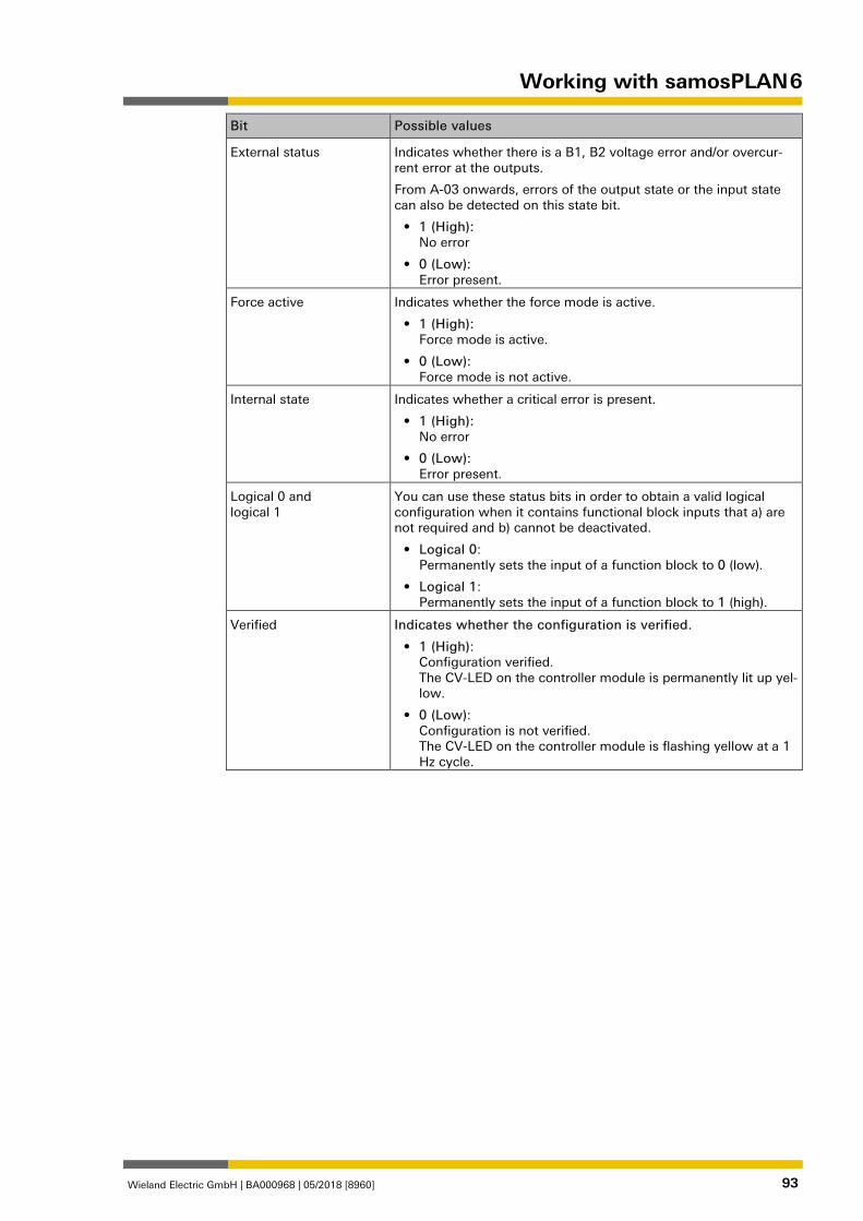
Working with samosPLAN 6
Wieland Electric GmbH | BA000968 | 05/2018 [8960] 93
Bit Possible values
External status Indicates whether there is a B1, B2 voltage error and/or overcur-rent error at the outputs.
From A-03 onwards, errors of the output state or the input state can also be detected on this state bit.
• 1 (High): No error
• 0 (Low): Error present.
Force active Indicates whether the force mode is active.
• 1 (High): Force mode is active.
• 0 (Low): Force mode is not active.
Internal state Indicates whether a critical error is present.
• 1 (High): No error
• 0 (Low): Error present.
Logical 0 and logical 1
You can use these status bits in order to obtain a valid logical configuration when it contains functional block inputs that a) are not required and b) cannot be deactivated.
• Logical 0: Permanently sets the input of a function block to 0 (low).
• Logical 1: Permanently sets the input of a function block to 1 (high).
Verified Indicates whether the configuration is verified.
• 1 (High): Configuration verified. The CV-LED on the controller module is permanently lit up yel-low.
• 0 (Low): Configuration is not verified. The CV-LED on the controller module is flashing yellow at a 1 Hz cycle.
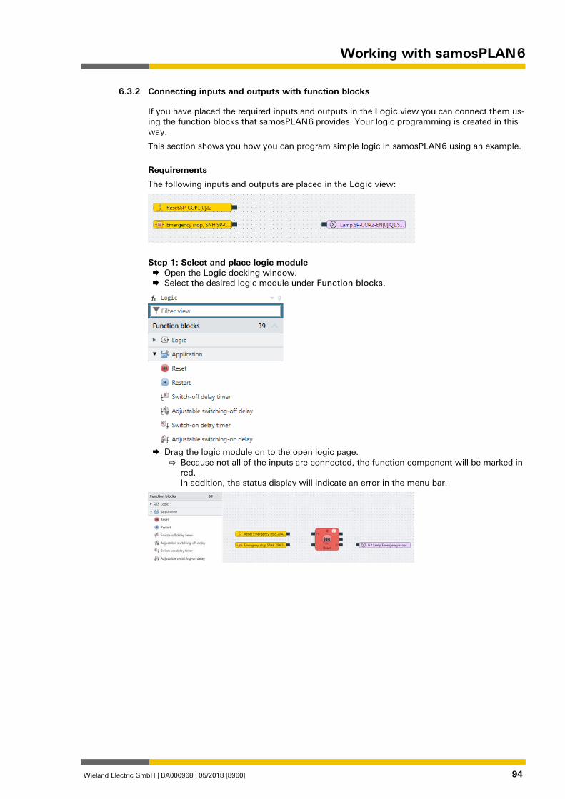
Working with samosPLAN 6
Wieland Electric GmbH | BA000968 | 05/2018 [8960] 94
Connecting inputs and outputs with function blocks 862953099
If you have placed the required inputs and outputs in the Logic view you can connect them us-ing the function blocks that samosPLAN 6 provides. Your logic programming is created in this way.
This section shows you how you can program simple logic in samosPLAN 6 using an example.
Requirements
The following inputs and outputs are placed in the Logic view:
Step 1: Select and place logic module Open the Logic docking window. Select the desired logic module under Function blocks.
Drag the logic module on to the open logic page.
⇨ Because not all of the inputs are connected, the function component will be marked in red. In addition, the status display will indicate an error in the menu bar.
6.3.2
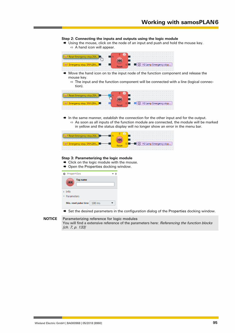
Working with samosPLAN 6
Wieland Electric GmbH | BA000968 | 05/2018 [8960] 95
Step 2: Connecting the inputs and outputs using the logic module Using the mouse, click on the node of an input and push and hold the mouse key.
⇨ A hand icon will appear.
Move the hand icon on to the input node of the function component and release the
mouse key. ⇨ The input and the function component will be connected with a line (logical connec-
tion).
In the same manner, establish the connection for the other input and for the output.
⇨ As soon as all inputs of the function module are connected, the module will be marked in yellow and the status display will no longer show an error in the menu bar.
Step 3: Parameterizing the logic module Click on the logic module with the mouse. Open the Properties docking window.
Set the desired parameters in the configuration dialog of the Properties docking window.
NOTICE Parameterizing reference for logic modules You will find a extensive reference of the parameters here: Referencing the function blocks [ch. 7, p. 133]
Working with samosPLAN 6
Wieland Electric GmbH | BA000968 | 05/2018 [8960] 96
Tips for working in the “Logic” view
Topic Tip
Interconnecting elements An alternative to the previously described procedure:
Using drag-and-drop, move an input or output over the node of the function block to which the connection is to be established.
Placing components You can move function blocks, inputs, and outputs anywhere you wish.
Click on them with the mouse and move them to the desired location.
As a placement aid, you can activate the grid points in the command bar.
Adding notes You can save text notes anywhere.
To do this, click with the right mouse key on the empty back-ground of the work area and select the Add note entry in the context menu.
Working with multiple pa-ges
In order to maintain an overview of an extensive project, you can create additional pages in the Logic view.
• Creating a new page: In the command bar, click on + Add page
• You can generate connections between the pages using a CPU flag or jump addresses.
Deleting connections To delete a project component or a connection:
• Click on the element.
• Press the button: Del.
Paste tag names directly in the Logic view
Double click on the input or output and write the desired tag name directly in the element.
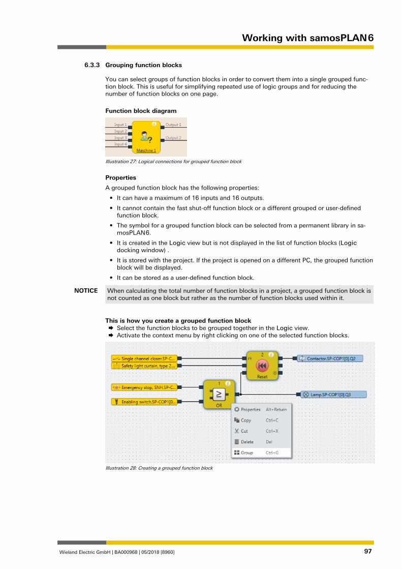
Working with samosPLAN 6
Wieland Electric GmbH | BA000968 | 05/2018 [8960] 97
Grouping function blocks 839837579
You can select groups of function blocks in order to convert them into a single grouped func-tion block. This is useful for simplifying repeated use of logic groups and for reducing the number of function blocks on one page.
Function block diagram
Illustration 27: Logical connections for grouped function block
Properties
A grouped function block has the following properties:
• It can have a maximum of 16 inputs and 16 outputs.
• It cannot contain the fast shut-off function block or a different grouped or user-defined function block.
• The symbol for a grouped function block can be selected from a permanent library in sa-mosPLAN 6.
• It is created in the Logic view but is not displayed in the list of function blocks (Logic docking window) .
• It is stored with the project. If the project is opened on a different PC, the grouped function block will be displayed.
• It can be stored as a user-defined function block.
NOTICE When calculating the total number of function blocks in a project, a grouped function block is not counted as one block but rather as the number of function blocks used within it.
This is how you create a grouped function block Select the function blocks to be grouped together in the Logic view. Activate the context menu by right clicking on one of the selected function blocks.
Illustration 28: Creating a grouped function block
6.3.3
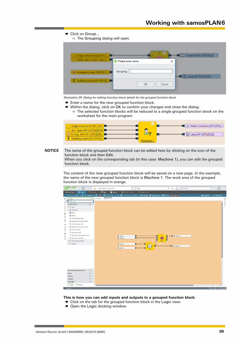
Working with samosPLAN 6
Wieland Electric GmbH | BA000968 | 05/2018 [8960] 98
Click on Group... ⇨ The Grouping dialog will open.
Illustration 29: Dialog for editing function block details for the grouped function block
Enter a name for the new grouped function block. Within the dialog, click on OK to confirm your changes and close the dialog.
⇨ The selected function blocks will be reduced to a single grouped function block on the worksheet for the main program.
NOTICE The name of the grouped function block can be edited here by clicking on the icon of the function block and then Edit. When you click on the corresponding tab (in this case: Machine 1), you can edit the grouped function block.
The content of the new grouped function block will be saved on a new page. In the example, the name of the new grouped function block is Machine 1. The work area of the grouped function block is displayed in orange.
This is how you can add inputs and outputs to a grouped function block. Click on the tab for the grouped function block in the Logic view. Open the Logic docking window.
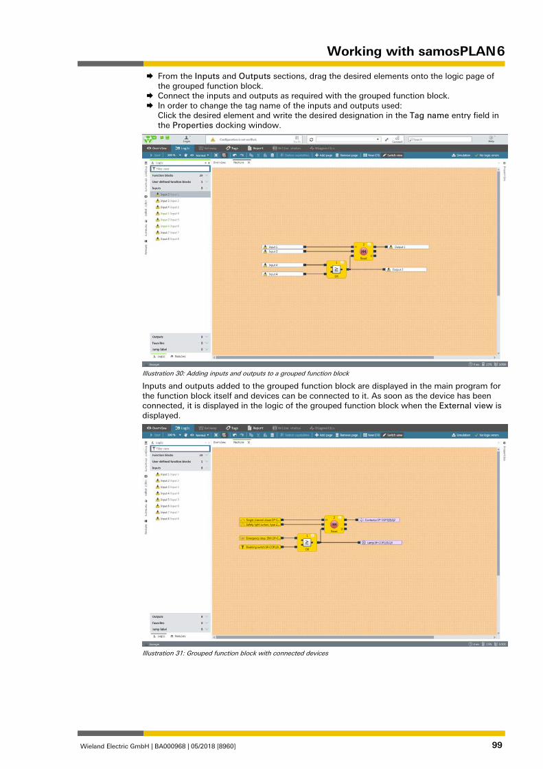
Working with samosPLAN 6
Wieland Electric GmbH | BA000968 | 05/2018 [8960] 99
From the Inputs and Outputs sections, drag the desired elements onto the logic page of the grouped function block.
Connect the inputs and outputs as required with the grouped function block. In order to change the tag name of the inputs and outputs used:
Click the desired element and write the desired designation in the Tag name entry field in the Properties docking window.
Illustration 30: Adding inputs and outputs to a grouped function block
Inputs and outputs added to the grouped function block are displayed in the main program for the function block itself and devices can be connected to it. As soon as the device has been connected, it is displayed in the logic of the grouped function block when the External view is displayed.
Illustration 31: Grouped function block with connected devices
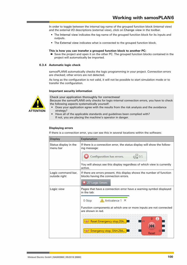
Working with samosPLAN 6
Wieland Electric GmbH | BA000968 | 05/2018 [8960] 100
In order to toggle between the internal tag name of the grouped function block (internal view) and the external I/O descriptions (external view), click on Change view in the toolbar.
• The Internal view indicates the tag name of the grouped function block for its inputs and outputs.
• The External view indicates what is connected to the grouped function block.
This is how you can transfer a grouped function block to another PC: Save the project and open it on the other PC. The grouped function blocks contained in the
project will automatically be imported.
Automatic logic check 862961803
samosPLAN 6 automatically checks the logic programming in your project. Connection errors are checked; other errors are not detected.
As long as the configuration is not valid, it will not be possible to start simulation mode or to transfer the configuration.
Important security information
ATTENTION
Check your application thoroughly for correctness! Because the samosPLAN 6 only checks for logic-internal connection errors, you have to check the following aspects systematically yourself: • Does your application agree with the results from the risk analysis and the avoidance
strategy? • Have all of the applicable standards and guidelines been complied with?
If not, you are placing the machine's operator in danger.
Displaying errors
If there is a connection error, you can see this in several locations within the software:
Display Explanation
Status display in the menu bar
If there is a connection error, the status display will show the follow-ing message:
You will always see this display regardless of which view is currently active.
Logic command bar, outside right
If there are errors present, this display shows the number of function blocks having the connection errors.
Logic view Pages that have a connection error have a warning symbol displayed
in the tab:
Function components at which one or more inputs are not connected are shown in red.
6.3.4

Working with samosPLAN 6
Wieland Electric GmbH | BA000968 | 05/2018 [8960] 101
Eliminating connection errors Connect all of the inputs at function blocks to the corresponding hardware inputs.
⇨ The function blocks are shown in yellow. ⇨ The error message in the Logic command bar and in the menu bar will be deleted.
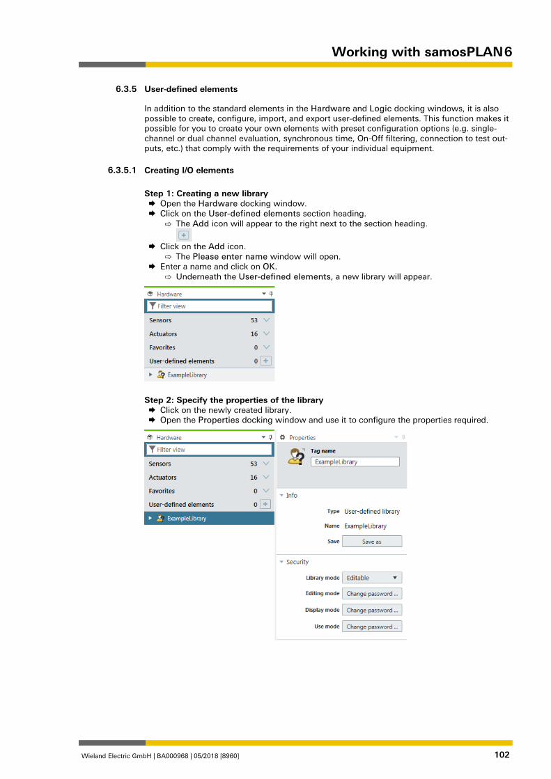
Working with samosPLAN 6
Wieland Electric GmbH | BA000968 | 05/2018 [8960] 102
User-defined elements 1278824971
In addition to the standard elements in the Hardware and Logic docking windows, it is also possible to create, configure, import, and export user-defined elements. This function makes it possible for you to create your own elements with preset configuration options (e.g. single-channel or dual channel evaluation, synchronous time, On-Off filtering, connection to test out-puts, etc.) that comply with the requirements of your individual equipment. 862936331
Creating I/O elements
Step 1: Creating a new library Open the Hardware docking window. Click on the User-defined elements section heading.
⇨ The Add icon will appear to the right next to the section heading.
Click on the Add icon.
⇨ The Please enter name window will open. Enter a name and click on OK.
⇨ Underneath the User-defined elements, a new library will appear.
Step 2: Specify the properties of the library Click on the newly created library. Open the Properties docking window and use it to configure the properties required.
6.3.5
6.3.5.1
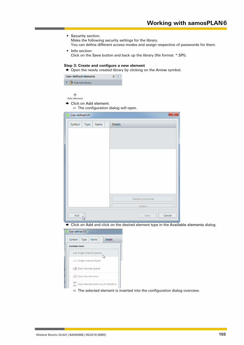
Working with samosPLAN 6
Wieland Electric GmbH | BA000968 | 05/2018 [8960] 103
• Security section: Make the following security settings for the library. You can define different access modes and assign respective of passwords for them.
• Info section: Click on the Save button and back up the library (file format: *.SPI).
Step 3: Create and configure a new element Open the newly created library by clicking on the Arrow symbol.
Click on Add element.
⇨ The configuration dialog will open.
Click on Add and click on the desired element type in the Available elements dialog.
⇨ The selected element is inserted into the configuration dialog overview.
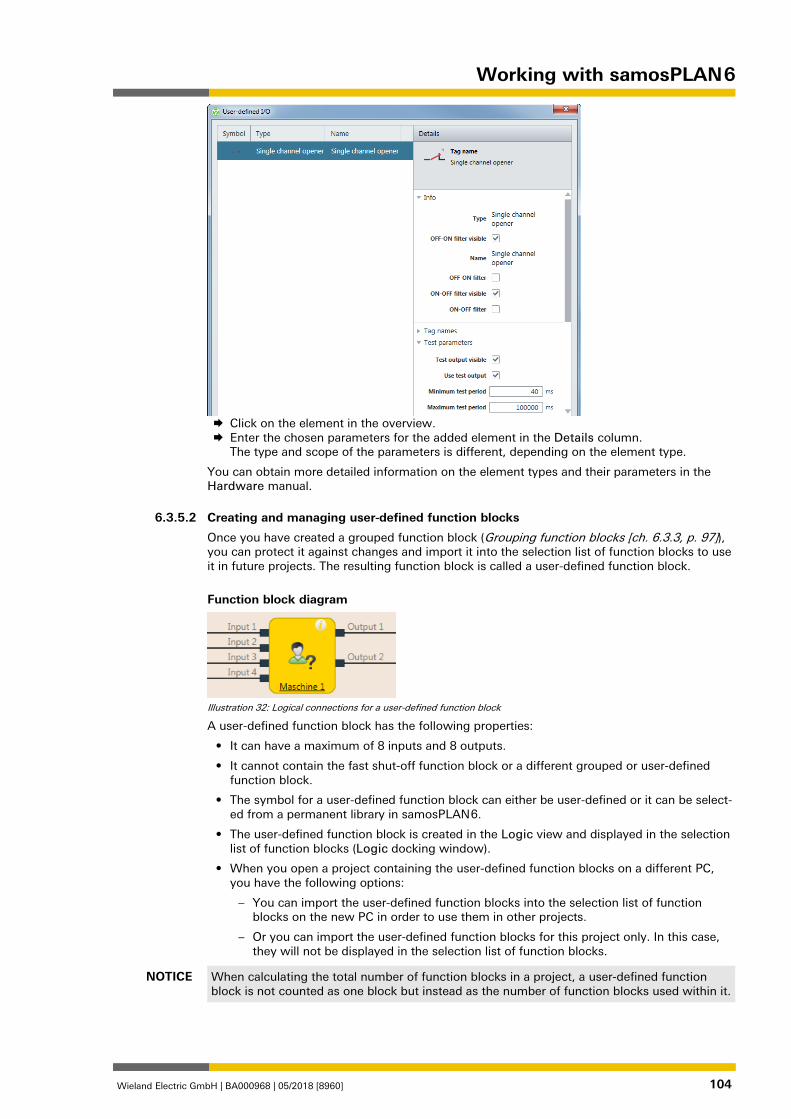
Working with samosPLAN 6
Wieland Electric GmbH | BA000968 | 05/2018 [8960] 104
Click on the element in the overview. Enter the chosen parameters for the added element in the Details column.
The type and scope of the parameters is different, depending on the element type.
You can obtain more detailed information on the element types and their parameters in the Hardware manual. 839852299
Creating and managing user-defined function blocks
Once you have created a grouped function block (Grouping function blocks [ch. 6.3.3, p. 97]), you can protect it against changes and import it into the selection list of function blocks to use it in future projects. The resulting function block is called a user-defined function block.
Function block diagram
Illustration 32: Logical connections for a user-defined function block
A user-defined function block has the following properties:
• It can have a maximum of 8 inputs and 8 outputs.
• It cannot contain the fast shut-off function block or a different grouped or user-defined function block.
• The symbol for a user-defined function block can either be user-defined or it can be select-ed from a permanent library in samosPLAN 6.
• The user-defined function block is created in the Logic view and displayed in the selection list of function blocks (Logic docking window).
• When you open a project containing the user-defined function blocks on a different PC, you have the following options:
– You can import the user-defined function blocks into the selection list of function blocks on the new PC in order to use them in other projects.
– Or you can import the user-defined function blocks for this project only. In this case, they will not be displayed in the selection list of function blocks.
NOTICE When calculating the total number of function blocks in a project, a user-defined function block is not counted as one block but instead as the number of function blocks used within it.
6.3.5.2
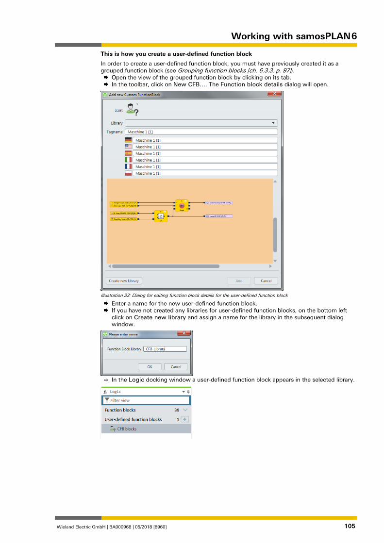
Working with samosPLAN 6
Wieland Electric GmbH | BA000968 | 05/2018 [8960] 105
This is how you create a user-defined function block
In order to create a user-defined function block, you must have previously created it as a grouped function block (see Grouping function blocks [ch. 6.3.3, p. 97]). Open the view of the grouped function block by clicking on its tab. In the toolbar, click on New CFB.... The Function block details dialog will open.
Illustration 33: Dialog for editing function block details for the user-defined function block
Enter a name for the new user-defined function block. If you have not created any libraries for user-defined function blocks, on the bottom left
click on Create new library and assign a name for the library in the subsequent dialog window.
⇨ In the Logic docking window a user-defined function block appears in the selected library.
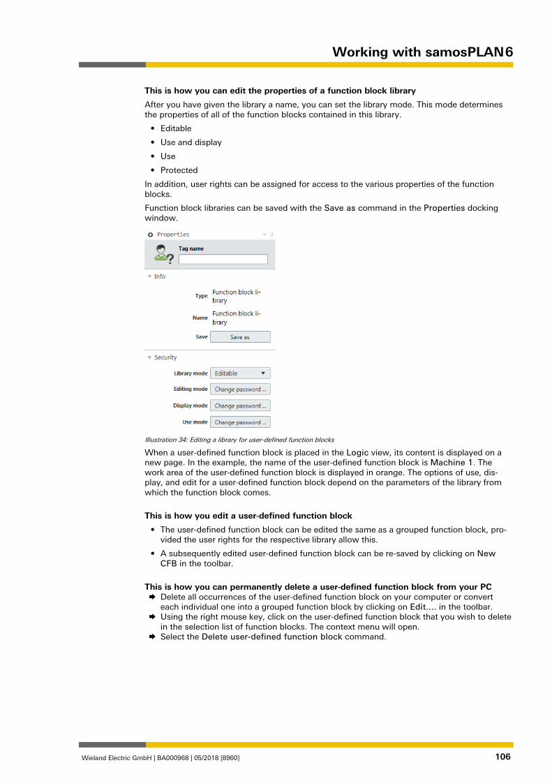
Working with samosPLAN 6
Wieland Electric GmbH | BA000968 | 05/2018 [8960] 106
This is how you can edit the properties of a function block library
After you have given the library a name, you can set the library mode. This mode determines the properties of all of the function blocks contained in this library.
• Editable
• Use and display
• Use
• Protected
In addition, user rights can be assigned for access to the various properties of the function blocks.
Function block libraries can be saved with the Save as command in the Properties docking window.
Illustration 34: Editing a library for user-defined function blocks
When a user-defined function block is placed in the Logic view, its content is displayed on a new page. In the example, the name of the user-defined function block is Machine 1. The work area of the user-defined function block is displayed in orange. The options of use, dis-play, and edit for a user-defined function block depend on the parameters of the library from which the function block comes.
This is how you edit a user-defined function block
• The user-defined function block can be edited the same as a grouped function block, pro-vided the user rights for the respective library allow this.
• A subsequently edited user-defined function block can be re-saved by clicking on New CFB in the toolbar.
This is how you can permanently delete a user-defined function block from your PC Delete all occurrences of the user-defined function block on your computer or convert
each individual one into a grouped function block by clicking on Edit.... in the toolbar. Using the right mouse key, click on the user-defined function block that you wish to delete
in the selection list of function blocks. The context menu will open. Select the Delete user-defined function block command.
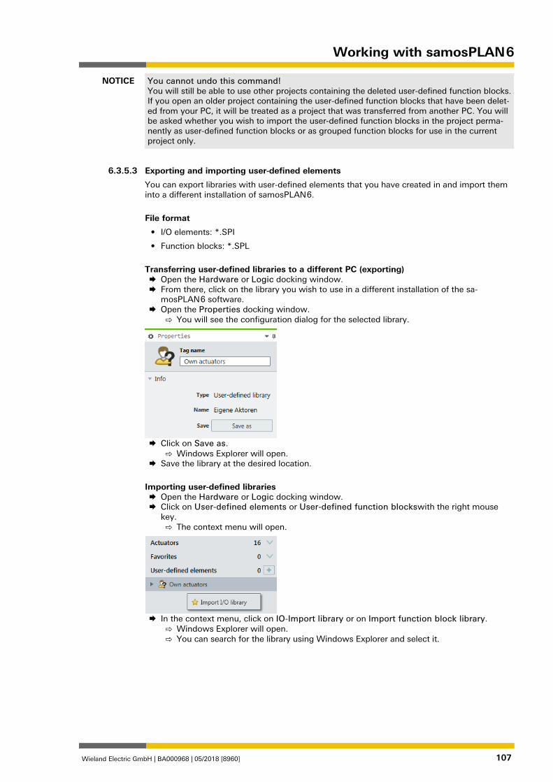
Working with samosPLAN 6
Wieland Electric GmbH | BA000968 | 05/2018 [8960] 107
NOTICE You cannot undo this command! You will still be able to use other projects containing the deleted user-defined function blocks. If you open an older project containing the user-defined function blocks that have been delet-ed from your PC, it will be treated as a project that was transferred from another PC. You will be asked whether you wish to import the user-defined function blocks in the project perma-nently as user-defined function blocks or as grouped function blocks for use in the current project only.
862937867
Exporting and importing user-defined elements
You can export libraries with user-defined elements that you have created in and import them into a different installation of samosPLAN 6.
File format
• I/O elements: *.SPI
• Function blocks: *.SPL
Transferring user-defined libraries to a different PC (exporting) Open the Hardware or Logic docking window. From there, click on the library you wish to use in a different installation of the sa-
mosPLAN 6 software. Open the Properties docking window.
⇨ You will see the configuration dialog for the selected library.
Click on Save as.
⇨ Windows Explorer will open. Save the library at the desired location.
Importing user-defined libraries Open the Hardware or Logic docking window. Click on User-defined elements or User-defined function blockswith the right mouse
key. ⇨ The context menu will open.
In the context menu, click on IO-Import library or on Import function block library.
⇨ Windows Explorer will open. ⇨ You can search for the library using Windows Explorer and select it.
6.3.5.3
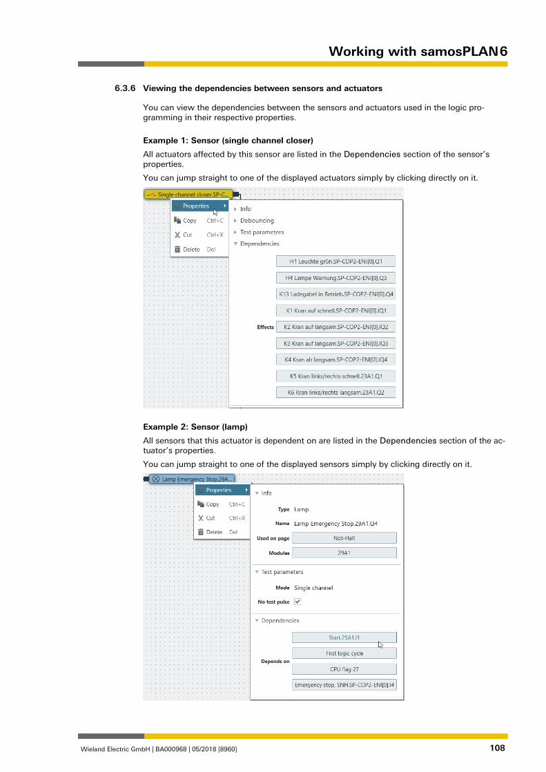
Working with samosPLAN 6
Wieland Electric GmbH | BA000968 | 05/2018 [8960] 108
Viewing the dependencies between sensors and actuators 1384366475
You can view the dependencies between the sensors and actuators used in the logic pro-gramming in their respective properties.
Example 1: Sensor (single channel closer)
All actuators affected by this sensor are listed in the Dependencies section of the sensor’s properties.
You can jump straight to one of the displayed actuators simply by clicking directly on it.
Example 2: Sensor (lamp)
All sensors that this actuator is dependent on are listed in the Dependencies section of the ac-tuator’s properties.
You can jump straight to one of the displayed sensors simply by clicking directly on it.
6.3.6
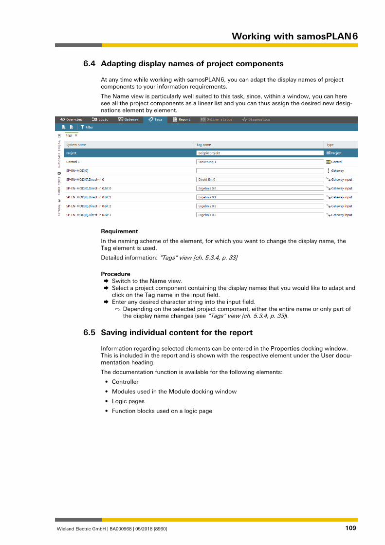
Working with samosPLAN 6
Wieland Electric GmbH | BA000968 | 05/2018 [8960] 109
Adapting display names of project components 862989707
At any time while working with samosPLAN 6, you can adapt the display names of project components to your information requirements.
The Name view is particularly well suited to this task, since, within a window, you can here see all the project components as a linear list and you can thus assign the desired new desig-nations element by element.
Requirement
In the naming scheme of the element, for which you want to change the display name, the Tag element is used.
Detailed information: "Tags" view [ch. 5.3.4, p. 33]
Procedure Switch to the Name view. Select a project component containing the display names that you would like to adapt and
click on the Tag name in the input field. Enter any desired character string into the input field.
⇨ Depending on the selected project component, either the entire name or only part of the display name changes (see "Tags" view [ch. 5.3.4, p. 33]).
Saving individual content for the report 1326756747
Information regarding selected elements can be entered in the Properties docking window. This is included in the report and is shown with the respective element under the User docu-mentation heading.
The documentation function is available for the following elements:
• Controller
• Modules used in the Module docking window
• Logic pages
• Function blocks used on a logic page
6.4
6.5
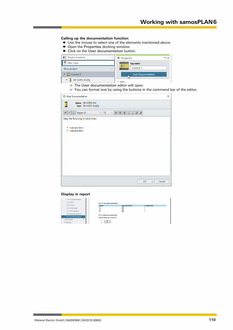
Working with samosPLAN 6
Wieland Electric GmbH | BA000968 | 05/2018 [8960] 110
Calling up the documentation function Use the mouse to select one of the elements mentioned above. Open the Properties docking window. Click on the User documentation button.
⇨ The User documentation editor will open. ⇨ You can format text by using the buttons in the command bar of the editor.
Display in report
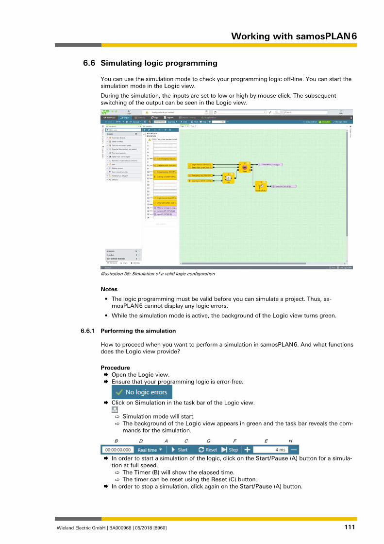
Working with samosPLAN 6
Wieland Electric GmbH | BA000968 | 05/2018 [8960] 111
Simulating logic programming 839257355
You can use the simulation mode to check your programming logic off-line. You can start the simulation mode in the Logic view.
During the simulation, the inputs are set to low or high by mouse click. The subsequent switching of the output can be seen in the Logic view.
Illustration 35: Simulation of a valid logic configuration
Notes
• The logic programming must be valid before you can simulate a project. Thus, sa-mosPLAN 6 cannot display any logic errors.
• While the simulation mode is active, the background of the Logic view turns green.
Performing the simulation 1284156811
How to proceed when you want to perform a simulation in samosPLAN 6. And what functions does the Logic view provide?
Procedure Open the Logic view. Ensure that your programming logic is error-free.
Click on Simulation in the task bar of the Logic view.
⇨ Simulation mode will start. ⇨ The background of the Logic view appears in green and the task bar reveals the com-
mands for the simulation.
In order to start a simulation of the logic, click on the Start/Pause (A) button for a simula-
tion at full speed. ⇨ The Timer (B) will show the elapsed time. ⇨ The timer can be reset using the Reset (C) button.
In order to stop a simulation, click again on the Start/Pause (A) button.
6.6
6.6.1
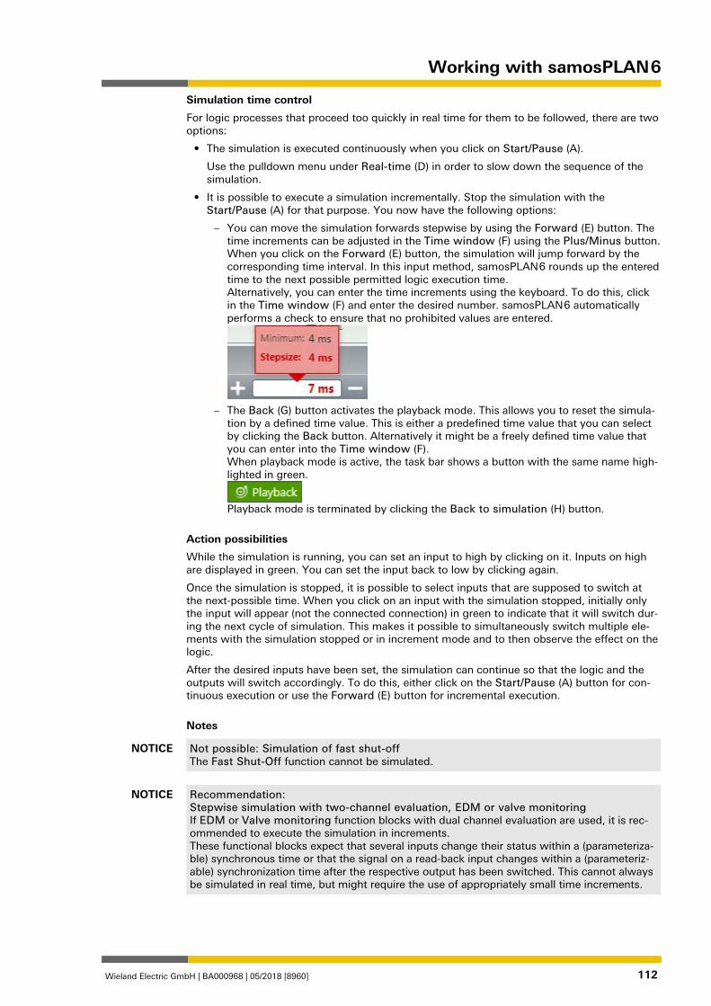
Working with samosPLAN 6
Wieland Electric GmbH | BA000968 | 05/2018 [8960] 112
Simulation time control
For logic processes that proceed too quickly in real time for them to be followed, there are two options:
• The simulation is executed continuously when you click on Start/Pause (A).
Use the pulldown menu under Real-time (D) in order to slow down the sequence of the simulation.
• It is possible to execute a simulation incrementally. Stop the simulation with the Start/Pause (A) for that purpose. You now have the following options:
– You can move the simulation forwards stepwise by using the Forward (E) button. The time increments can be adjusted in the Time window (F) using the Plus/Minus button. When you click on the Forward (E) button, the simulation will jump forward by the corresponding time interval. In this input method, samosPLAN 6 rounds up the entered time to the next possible permitted logic execution time. Alternatively, you can enter the time increments using the keyboard. To do this, click in the Time window (F) and enter the desired number. samosPLAN 6 automatically performs a check to ensure that no prohibited values are entered.
– The Back (G) button activates the playback mode. This allows you to reset the simula-
tion by a defined time value. This is either a predefined time value that you can select by clicking the Back button. Alternatively it might be a freely defined time value that you can enter into the Time window (F). When playback mode is active, the task bar shows a button with the same name high-lighted in green.
Playback mode is terminated by clicking the Back to simulation (H) button.
Action possibilities
While the simulation is running, you can set an input to high by clicking on it. Inputs on high are displayed in green. You can set the input back to low by clicking again.
Once the simulation is stopped, it is possible to select inputs that are supposed to switch at the next-possible time. When you click on an input with the simulation stopped, initially only the input will appear (not the connected connection) in green to indicate that it will switch dur-ing the next cycle of simulation. This makes it possible to simultaneously switch multiple ele-ments with the simulation stopped or in increment mode and to then observe the effect on the logic.
After the desired inputs have been set, the simulation can continue so that the logic and the outputs will switch accordingly. To do this, either click on the Start/Pause (A) button for con-tinuous execution or use the Forward (E) button for incremental execution.
Notes
NOTICE Not possible: Simulation of fast shut-off The Fast Shut-Off function cannot be simulated.
NOTICE Recommendation: Stepwise simulation with two-channel evaluation, EDM or valve monitoring If EDM or Valve monitoring function blocks with dual channel evaluation are used, it is rec-ommended to execute the simulation in increments. These functional blocks expect that several inputs change their status within a (parameteriza-ble) synchronous time or that the signal on a read-back input changes within a (parameteriz-able) synchronization time after the respective output has been switched. This cannot always be simulated in real time, but might require the use of appropriately small time increments.
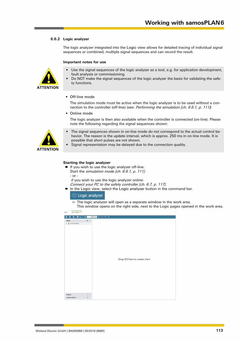
Working with samosPLAN 6
Wieland Electric GmbH | BA000968 | 05/2018 [8960] 113
Logic analyzer 1284179723
The logic analyzer integrated into the Logic view allows for detailed tracing of individual signal sequences or combined, multiple signal sequences and can record the result.
Important notes for use
ATTENTION
• Use the signal sequences of the logic analyzer as a tool, e.g. for application development, fault analysis or commissioning.
• Do NOT make the signal sequences of the logic analyzer the basis for validating the safe-ty functions.
• Off-line mode
The simulation mode must be active when the logic analyzer is to be used without a con-nection to the controller (off-line) (see: Performing the simulation [ch. 6.6.1, p. 111])
• Online mode
The logic analyzer is then also available when the controller is connected (on-line). Please note the following regarding the signal sequences shown:
ATTENTION
• The signal sequences shown in on-line mode do not correspond to the actual control be-havior. The reason is the update interval, which is approx. 250 ms in on-line mode. It is possible that short pulses are not shown.
• Signal representation may be delayed due to the connection quality.
Starting the logic analyzer If you wish to use the logic analyzer off-line:
Start the simulation mode [ch. 6.6.1, p. 111]. - or - if you wish to use the logic analyzer online: Connect your PC to the safety controller [ch. 6.7, p. 117].
In the Logic view, select the Logic analyzer button in the command bar.
⇨ The logic analyzer will open as a separate window in the work area.
This window opens on the right side, next to the Logic pages opened in the work area.
6.6.2

Working with samosPLAN 6
Wieland Electric GmbH | BA000968 | 05/2018 [8960] 114
Adding inputs and outputs Pull the desired inputs out of the left bar and onto the area of the logic analyzer.
Pull the desired outputs out of the left bar and into the area of the logic analyzer.
Example
Logic analyzer with two signal sequences:
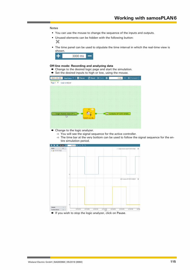
Working with samosPLAN 6
Wieland Electric GmbH | BA000968 | 05/2018 [8960] 115
Notes
• You can use the mouse to change the sequence of the inputs and outputs.
• Unused elements can be hidden with the following button:
• The time panel can be used to stipulate the time interval in which the real-time view is
shown.
Off-line mode: Recording and analyzing data Change to the desired logic page and start the simulation. Set the desired inputs to high or low, using the mouse.
Change to the logic analyzer.
⇨ You will see the signal sequence for the active controller. ⇨ The time bar at the very bottom can be used to follow the signal sequence for the en-
tire simulation period.
If you wish to stop the logic analyzer, click on Pause.
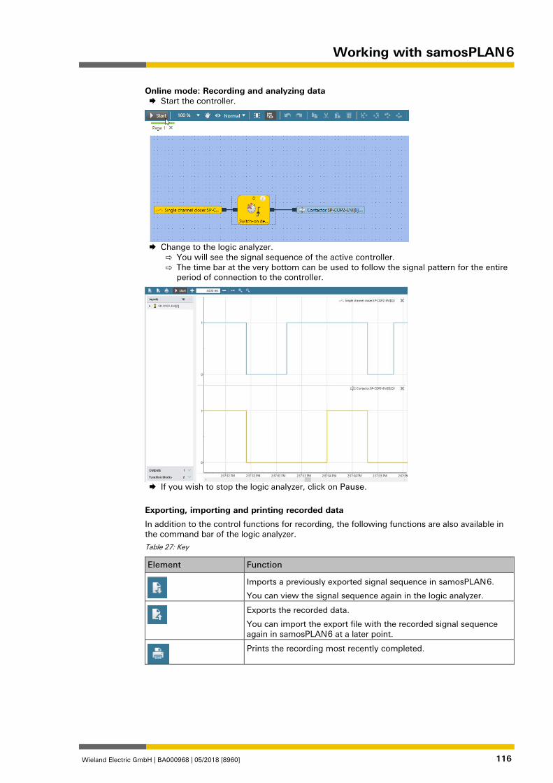
Working with samosPLAN 6
Wieland Electric GmbH | BA000968 | 05/2018 [8960] 116
Online mode: Recording and analyzing data Start the controller.
Change to the logic analyzer.
⇨ You will see the signal sequence of the active controller. ⇨ The time bar at the very bottom can be used to follow the signal pattern for the entire
period of connection to the controller.
If you wish to stop the logic analyzer, click on Pause.
Exporting, importing and printing recorded data
In addition to the control functions for recording, the following functions are also available in the command bar of the logic analyzer.
Table 27: Key
Element Function
Imports a previously exported signal sequence in samosPLAN 6.
You can view the signal sequence again in the logic analyzer.
Exports the recorded data.
You can import the export file with the recorded signal sequence again in samosPLAN 6 at a later point.
Prints the recording most recently completed.
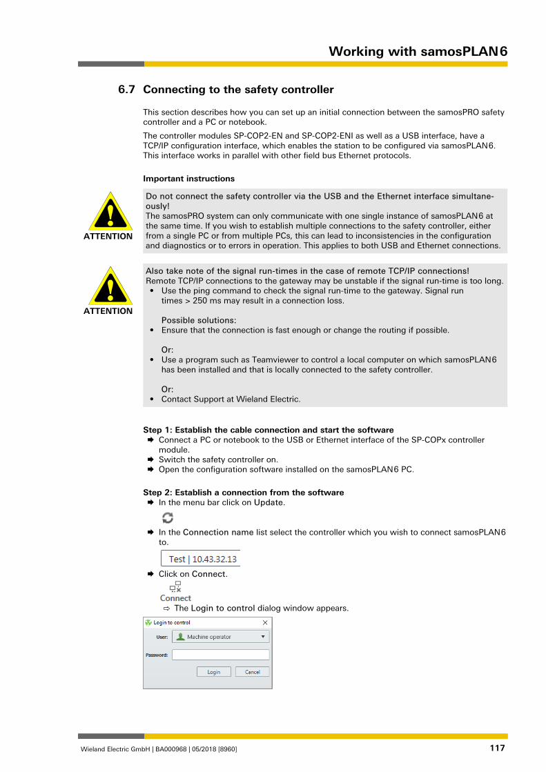
Working with samosPLAN 6
Wieland Electric GmbH | BA000968 | 05/2018 [8960] 117
Connecting to the safety controller 840167563
This section describes how you can set up an initial connection between the samosPRO safety controller and a PC or notebook.
The controller modules SP-COP2-EN and SP-COP2-ENI as well as a USB interface, have a TCP/IP configuration interface, which enables the station to be configured via samosPLAN 6. This interface works in parallel with other field bus Ethernet protocols.
Important instructions
ATTENTION
Do not connect the safety controller via the USB and the Ethernet interface simultane-ously! The samosPRO system can only communicate with one single instance of samosPLAN 6 at the same time. If you wish to establish multiple connections to the safety controller, either from a single PC or from multiple PCs, this can lead to inconsistencies in the configuration and diagnostics or to errors in operation. This applies to both USB and Ethernet connections.
ATTENTION
Also take note of the signal run-times in the case of remote TCP/IP connections! Remote TCP/IP connections to the gateway may be unstable if the signal run-time is too long. • Use the ping command to check the signal run-time to the gateway. Signal run
times > 250 ms may result in a connection loss. Possible solutions:
• Ensure that the connection is fast enough or change the routing if possible. Or:
• Use a program such as Teamviewer to control a local computer on which samosPLAN 6 has been installed and that is locally connected to the safety controller. Or:
• Contact Support at Wieland Electric.
Step 1: Establish the cable connection and start the software Connect a PC or notebook to the USB or Ethernet interface of the SP-COPx controller
module. Switch the safety controller on. Open the configuration software installed on the samosPLAN 6 PC.
Step 2: Establish a connection from the software In the menu bar click on Update.
In the Connection name list select the controller which you wish to connect samosPLAN 6
to.
Click on Connect.
⇨ The Login to control dialog window appears.
6.7
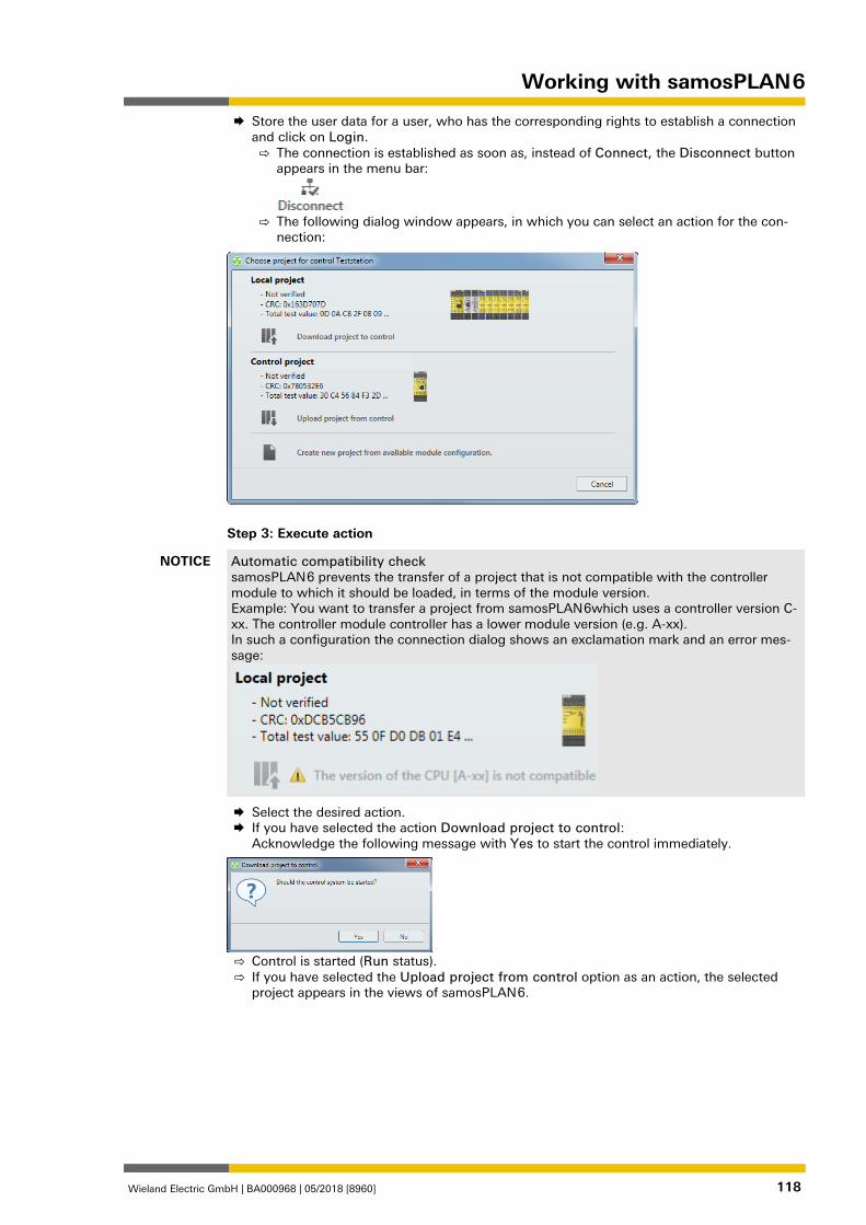
Working with samosPLAN 6
Wieland Electric GmbH | BA000968 | 05/2018 [8960] 118
Store the user data for a user, who has the corresponding rights to establish a connection and click on Login. ⇨ The connection is established as soon as, instead of Connect, the Disconnect button
appears in the menu bar:
⇨ The following dialog window appears, in which you can select an action for the con-
nection:
Step 3: Execute action
NOTICE Automatic compatibility check samosPLAN 6 prevents the transfer of a project that is not compatible with the controller module to which it should be loaded, in terms of the module version. Example: You want to transfer a project from samosPLAN 6which uses a controller version C-xx. The controller module controller has a lower module version (e.g. A-xx). In such a configuration the connection dialog shows an exclamation mark and an error mes-sage:
Select the desired action. If you have selected the action Download project to control:
Acknowledge the following message with Yes to start the control immediately.
⇨ Control is started (Run status). ⇨ If you have selected the Upload project from control option as an action, the selected
project appears in the views of samosPLAN 6.
Working with samosPLAN 6
Wieland Electric GmbH | BA000968 | 05/2018 [8960] 119
Transferring the system configuration 840304395
The configuration of the safety controller initially only exists as a project, i.e. as a samosPRO project file. This project file must be transferred to the samosPRO removable program storage SP-COP-CARD1 via the controller module.
NOTICE The removable program storage SP-COP-CARD1 and the controller modules communicate via an internal interface. It is also possible to connect a PC directly to the removable program storage SP-COP-CARD1. In this way, the project file can be directly transferred from samosPLAN 6 to the removable storage (further information: Saving the project file [ch. 6.1.7, p. 77]).
The configuration data are checked for compatibility during their transfer to the removable program storage and can subsequently be verified (by reading and comparing).
Transferring verified project data to several safety controllers
The removable program storage can, for example, be used on a PC to copy the verified project data without further processing in the samosPLAN 6 software and transfer them to any number of samosPRO safety controllers. This process copies the configuration data without any changes, including the verification information that was determined when the first safety con-troller was configured with these data.
Transferring project data into the safety control 840305931
How to connect samosPLAN 6 with the safety control and how to transfer a project to the con-trol is explained here:
Connecting to the safety controller [ch. 6.7, p. 117]
Compatibility check 840306955
The configuration data contain an electronic type code and a version code for each module that is supposed to be configured. During transfer, each module checks whether it is compati-ble with the configuration data. The compatibility check is solely based on the functional part of the respective module, not on the hardware version; the design of the terminals, for exam-ple, is not included.
If the compatibility check has a negative result, a corresponding error message is generated in the respective module and in the controller module.
NOTICE Some modules in samosPLAN 6 have various version numbers stored, which means that a compatible module can be selected from a list underneath the module.
6.8
6.8.1
6.8.2
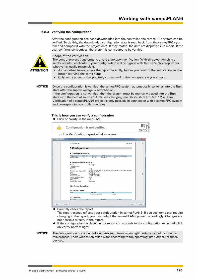
Working with samosPLAN 6
Wieland Electric GmbH | BA000968 | 05/2018 [8960] 120
Verifying the configuration 840308491
After the configuration has been downloaded into the controller, the samosPRO system can be verified. To do this, the downloaded configuration data is read back from the samosPRO sys-tem and compared with the project data. If they match, the data are displayed in a report. If the user confirms correctness, the system is considered to be verified.
ATTENTION
Scope of the verification The control project transforms to a safe state upon verification. With this step, which is a safety-oriented application, your configuration will be signed with the verification report, for whoever is legally responsible. • As described below, check the report carefully, before you confirm the verification via the
button carrying the same name. • Only verify projects that precisely correspond to the configuration you expect.
NOTICE Once the configuration is verified, the samosPRO system automatically switches into the Run state after the supply voltage is switched on. If the configuration is not verified, then the system must be manually placed into the Run state with the help of samosPLAN 6 (see Changing the device state [ch. 6.9.1.3, p. 126]). Verification of a samosPLAN 6 project is only possible in connection with a samosPRO system and corresponding controller modules.
This is how you can verify a configuration Click on Verify in the menu bar.
⇨ The Verification report window opens.
Carefully check the report.
The report exactly reflects your configuration in samosPLAN 6. If you see items that require changing in the report, you must adapt the samosPLAN 6 project accordingly. Changes are not possible directly in the report.
If the configuration displayed in the report corresponds to the configuration expected, click on Verify bottom right.
NOTICE The configuration of connected elements (e.g. from safety light curtains) is not included in this process. Their verification takes place according to the operating instructions for these devices.
6.8.3
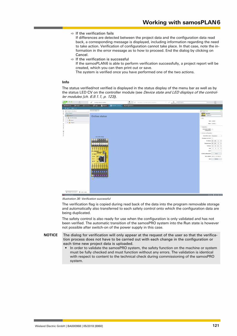
Working with samosPLAN 6
Wieland Electric GmbH | BA000968 | 05/2018 [8960] 121
⇨ If the verification fails If differences are detected between the project data and the configuration data read back, a corresponding message is displayed, including information regarding the need to take action. Verification of configuration cannot take place. In that case, note the in-formation in the error message as to how to proceed. End the dialog by clicking on Cancel.
⇨ If the verification is successful If the samosPLAN 6 is able to perform verification successfully, a project report will be created, which you can then print out or save. The system is verified once you have performed one of the two actions.
Info
The status verified/not verified is displayed in the status display of the menu bar as well as by the status LED CV on the controller module (see Device state and LED displays of the control-ler modules [ch. 6.9.1.1, p. 123]).
Illustration 36: Verification successful
The verification flag is copied during read back of the data into the program removable storage and automatically also transferred to each safety control onto which the configuration data are being duplicated.
The safety control is also ready for use when the configuration is only validated and has not been verified. The automatic transition of the samosPRO system into the Run state is however not possible after switch-on of the power supply in this case.
NOTICE The dialog for verification will only appear at the request of the user so that the verifica-tion process does not have to be carried out with each change in the configuration or each time new project data is uploaded. • In order to validate the samosPRO system, the safety function on the machine or system
must be fully checked and must function without any errors. The validation is identical with respect to content to the technical check during commissioning of the samosPRO system.
Working with samosPLAN 6
Wieland Electric GmbH | BA000968 | 05/2018 [8960] 122
Using the monitoring functions 863007627
With online controllers, you can use the following monitoring functions in the Module view and in the Diagnostics view of samosPLAN 6.
NOTICE You can read here how to connect samosPLAN 6 to a safety controller: Connecting to the safety controller [ch. 6.7, p. 117]
Observing the device states of the system 840317707
In the Modules view, you can observe the status of all installed modules, as well as the status of the inputs and outputs in live operation.
The following table provides an overview of the device states of the samosPRO system.
Some device states require user intervention, e.g. change of the state from Stop to Run (Changing the device state [ch. 6.9.1.3, p. 126]). Other states are based on the internal self-test of the samosPRO system, e.g. Internal errors.
6.9
6.9.1
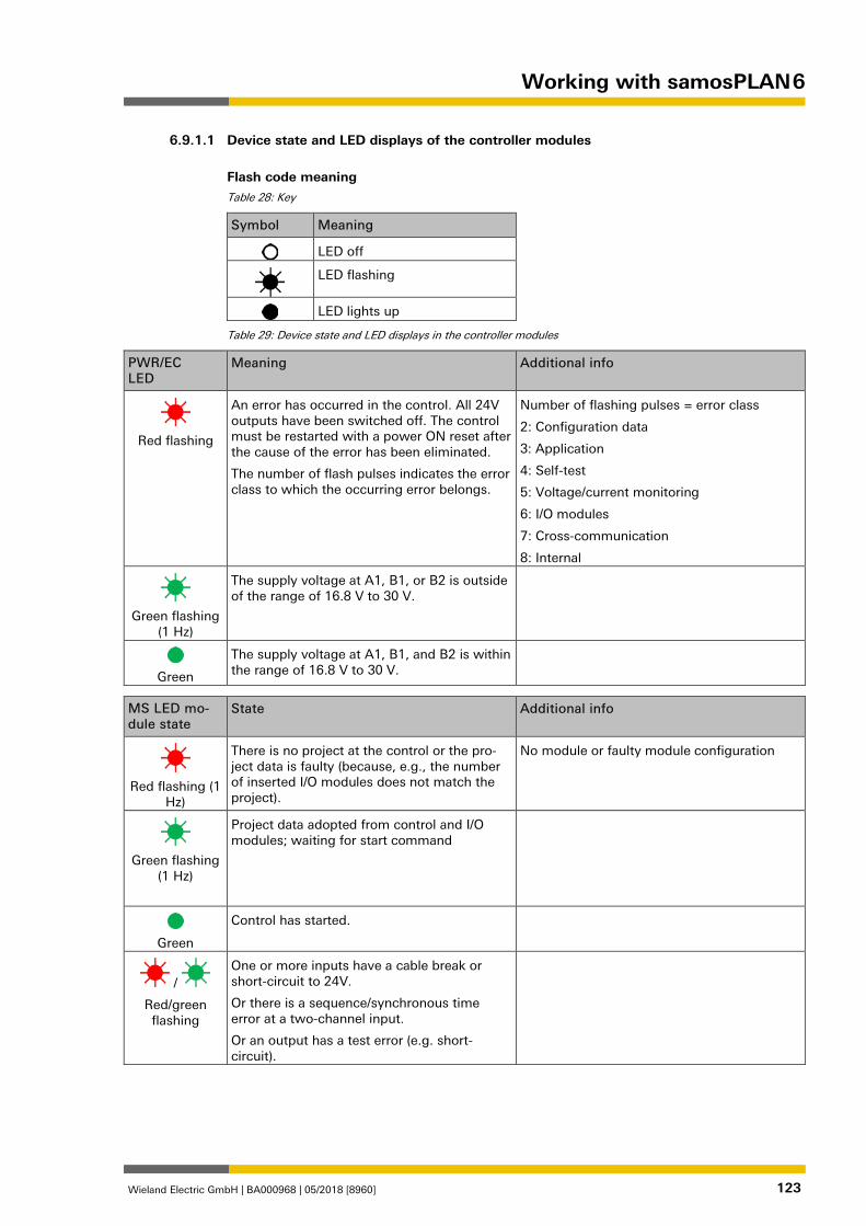
Working with samosPLAN 6
Wieland Electric GmbH | BA000968 | 05/2018 [8960] 123
958983179
Device state and LED displays of the controller modules
Flash code meaning Table 28: Key
Symbol Meaning
LED off
LED flashing
LED lights up
Table 29: Device state and LED displays in the controller modules
PWR/EC LED
Meaning Additional info
Red flashing
An error has occurred in the control. All 24V outputs have been switched off. The control must be restarted with a power ON reset after the cause of the error has been eliminated.
The number of flash pulses indicates the error class to which the occurring error belongs.
Number of flashing pulses = error class
2: Configuration data
3: Application
4: Self-test
5: Voltage/current monitoring
6: I/O modules
7: Cross-communication
8: Internal
Green flashing
(1 Hz)
The supply voltage at A1, B1, or B2 is outside of the range of 16.8 V to 30 V.
Green
The supply voltage at A1, B1, and B2 is within the range of 16.8 V to 30 V.
MS LED mo-dule state
State Additional info
Red flashing (1
Hz)
There is no project at the control or the pro-ject data is faulty (because, e.g., the number of inserted I/O modules does not match the project).
No module or faulty module configuration
Green flashing
(1 Hz)
Project data adopted from control and I/O modules; waiting for start command
Green
Control has started.
/
Red/green flashing
One or more inputs have a cable break or short-circuit to 24V.
Or there is a sequence/synchronous time error at a two-channel input.
Or an output has a test error (e.g. short-circuit).
6.9.1.1
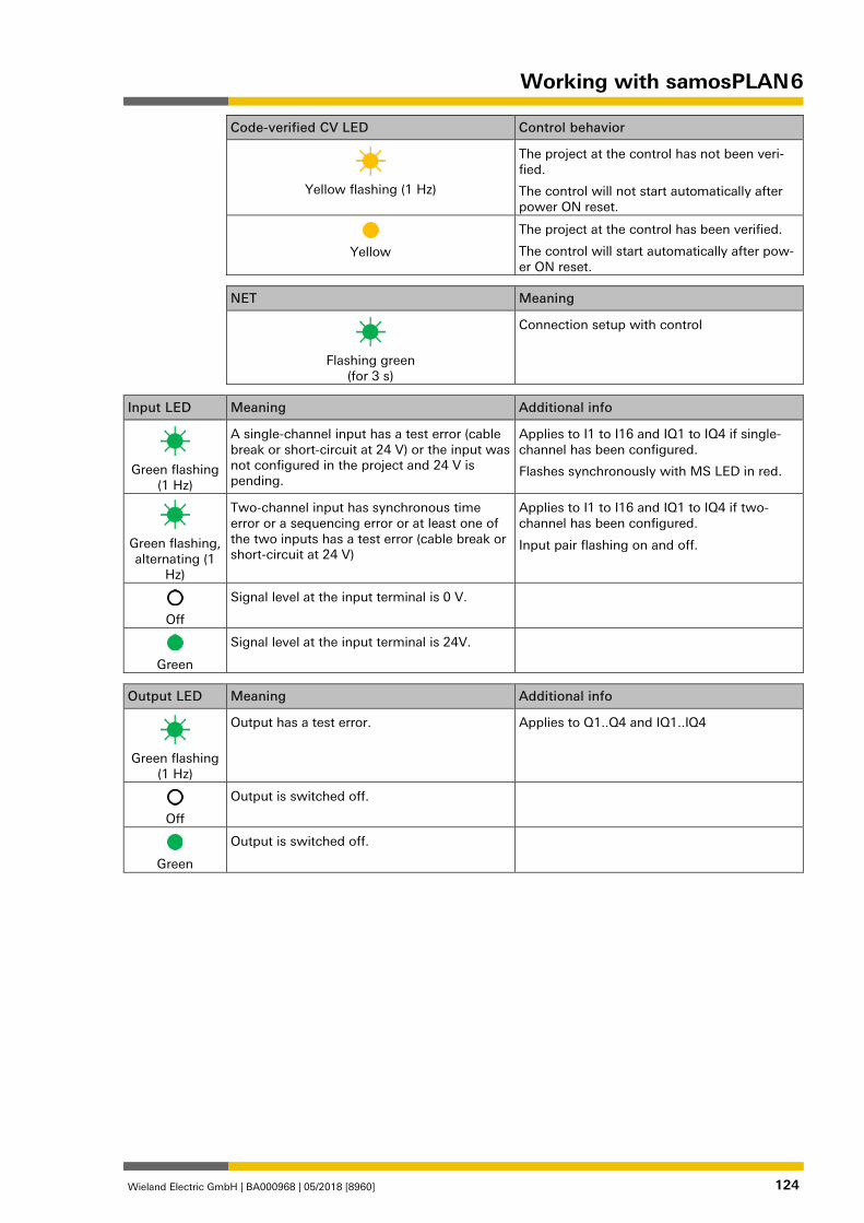
Working with samosPLAN 6
Wieland Electric GmbH | BA000968 | 05/2018 [8960] 124
Code-verified CV LED Control behavior
Yellow flashing (1 Hz)
The project at the control has not been veri-fied.
The control will not start automatically after power ON reset.
Yellow
The project at the control has been verified.
The control will start automatically after pow-er ON reset.
NET Meaning
Flashing green
(for 3 s)
Connection setup with control
Input LED Meaning Additional info
Green flashing
(1 Hz)
A single-channel input has a test error (cable break or short-circuit at 24 V) or the input was not configured in the project and 24 V is pending.
Applies to I1 to I16 and IQ1 to IQ4 if single-channel has been configured.
Flashes synchronously with MS LED in red.
Green flashing, alternating (1
Hz)
Two-channel input has synchronous time error or a sequencing error or at least one of the two inputs has a test error (cable break or short-circuit at 24 V)
Applies to I1 to I16 and IQ1 to IQ4 if two-channel has been configured.
Input pair flashing on and off.
Off
Signal level at the input terminal is 0 V.
Green
Signal level at the input terminal is 24V.
Output LED Meaning Additional info
Green flashing
(1 Hz)
Output has a test error. Applies to Q1..Q4 and IQ1..IQ4
Off
Output is switched off.
Green
Output is switched off.
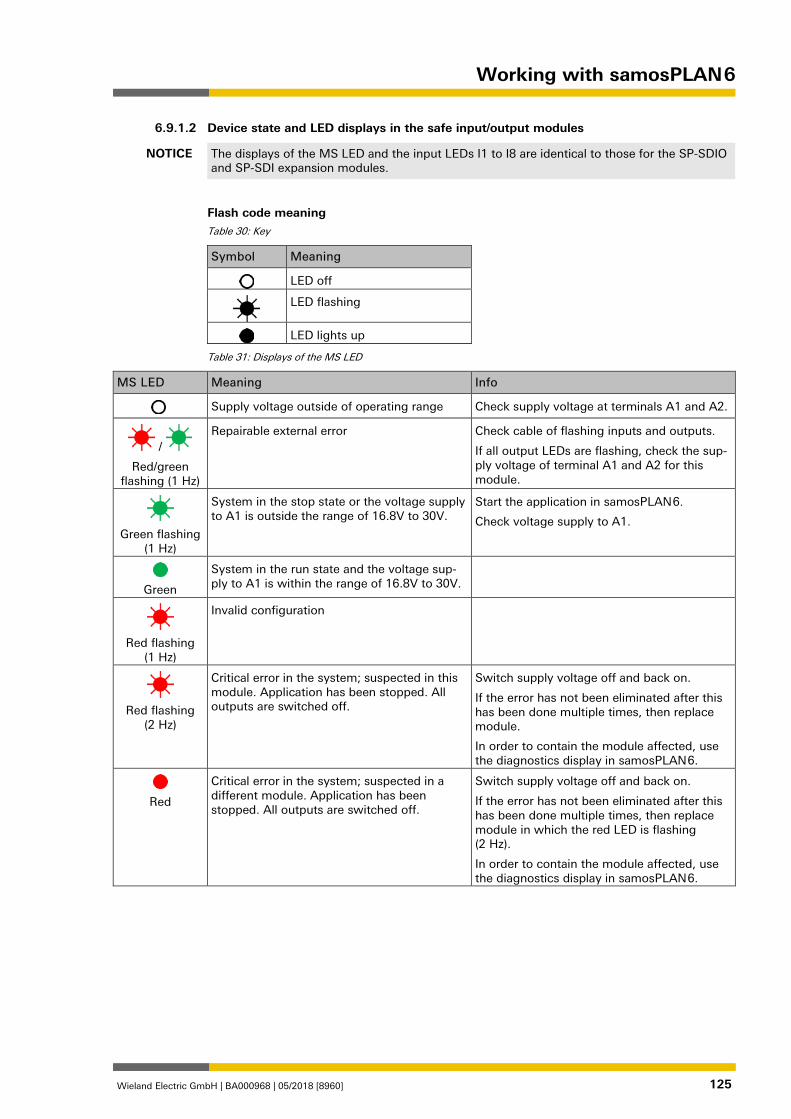
Working with samosPLAN 6
Wieland Electric GmbH | BA000968 | 05/2018 [8960] 125
958986123
Device state and LED displays in the safe input/output modules
NOTICE The displays of the MS LED and the input LEDs I1 to I8 are identical to those for the SP-SDIO and SP-SDI expansion modules.
Flash code meaning Table 30: Key
Symbol Meaning
LED off
LED flashing
LED lights up
Table 31: Displays of the MS LED
MS LED Meaning Info
Supply voltage outside of operating range Check supply voltage at terminals A1 and A2.
/
Red/green flashing (1 Hz)
Repairable external error Check cable of flashing inputs and outputs.
If all output LEDs are flashing, check the sup-ply voltage of terminal A1 and A2 for this module.
Green flashing
(1 Hz)
System in the stop state or the voltage supply to A1 is outside the range of 16.8V to 30V.
Start the application in samosPLAN 6.
Check voltage supply to A1.
Green
System in the run state and the voltage sup-ply to A1 is within the range of 16.8V to 30V.
Red flashing
(1 Hz)
Invalid configuration
Red flashing
(2 Hz)
Critical error in the system; suspected in this module. Application has been stopped. All outputs are switched off.
Switch supply voltage off and back on.
If the error has not been eliminated after this has been done multiple times, then replace module.
In order to contain the module affected, use the diagnostics display in samosPLAN 6.
Red
Critical error in the system; suspected in a different module. Application has been stopped. All outputs are switched off.
Switch supply voltage off and back on.
If the error has not been eliminated after this has been done multiple times, then replace module in which the red LED is flashing (2 Hz).
In order to contain the module affected, use the diagnostics display in samosPLAN 6.
6.9.1.2
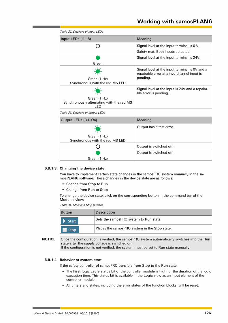
Working with samosPLAN 6
Wieland Electric GmbH | BA000968 | 05/2018 [8960] 126
Table 32: Displays of input LEDs
Input LEDs (I1–I8) Meaning
Signal level at the input terminal is 0 V.
Safety mat: Both inputs actuated.
Green
Signal level at the input terminal is 24V.
Green (1 Hz)
Synchronous with the red MS LED
Signal level at the input terminal is 0V and a repairable error at a two-channel input is pending.
Green (1 Hz)
Synchronously alternating with the red MS LED
Signal level at the input is 24V and a repaira-ble error is pending.
Table 33: Displays of output LEDs
Output LEDs (Q1–Q4) Meaning
Green (1 Hz)
Synchronous with the red MS LED
Output has a test error.
Output is switched off.
Green (1 Hz)
Output is switched off.
840323723
Changing the device state
You have to implement certain state changes in the samosPRO system manually in the sa-mosPLAN 6 software. These changes in the device state are as follows:
• Change from Stop to Run
• Change from Run to Stop
To change the device state, click on the corresponding button in the command bar of the Modules view:
Table 34: Start and Stop buttons
Button Description
Sets the samosPRO system to Run state.
Places the samosPRO system in the Stop state.
NOTICE Once the configuration is verified, the samosPRO system automatically switches into the Run state after the supply voltage is switched on. If the configuration is not verified, the system must be set to Run state manually.
840331147
Behavior at system start
If the safety controller of samosPRO transfers from Stop to the Run state:
• The First logic cycle status bit of the controller module is high for the duration of the logic execution time. This status bit is available in the Logic view as an input element of the controller module.
• All timers and states, including the error states of the function blocks, will be reset.
6.9.1.3
6.9.1.4
Working with samosPLAN 6
Wieland Electric GmbH | BA000968 | 05/2018 [8960] 127
Forcing inputs (Force mode) 840243979
Inputs and undetermined outputs, for example of the gateways, can be forced while the con-troller is connected, when the ForcingRun state in the Logic view is selected.
This means that you can set inputs high or low controlled by software, regardless of the actual value of the physical inputs. In this case, the samosPRO system, including the programmed logic, will behave precisely as if the physical inputs or outputs had actually assumed the re-spective value.
This will make it possible to test the wiring of your system in online mode and to check the function of your logic program, for example, during commissioning or maintenance.
Technical information
• With force mode, you can only directly influence inputs in the logic of a samosPRO system but not safe outputs or logic events, such as function blocks or jump labels.
• The force mode is only available during the first 18 hours after switching on the controller (Power on). When the controller module has been switched on for longer, switch it off and on again to be able to activate force mode.
Safety information
ATTENTION
Ensure that there can be no danger to people or damage to equipment! In force mode, you can freely influence the value of the safety inputs. By doing so, you can cancel the protective function of your safety equipment and induce a hazardous situation. • Make sure that no one is in the hazardous area of your machine or system before you
activate force mode. • Make sure that no one can enter the hazardous area of the machine or system during the
time that force mode is active. • Additional safety measures may be necessary when force mode is used.
ATTENTION
Do not use force mode simultaneously on multiple PCs. When using force mode: • Make sure that no one can also activate force mode from a second PC. This could result
in a hazard-inducing condition.
6.9.2
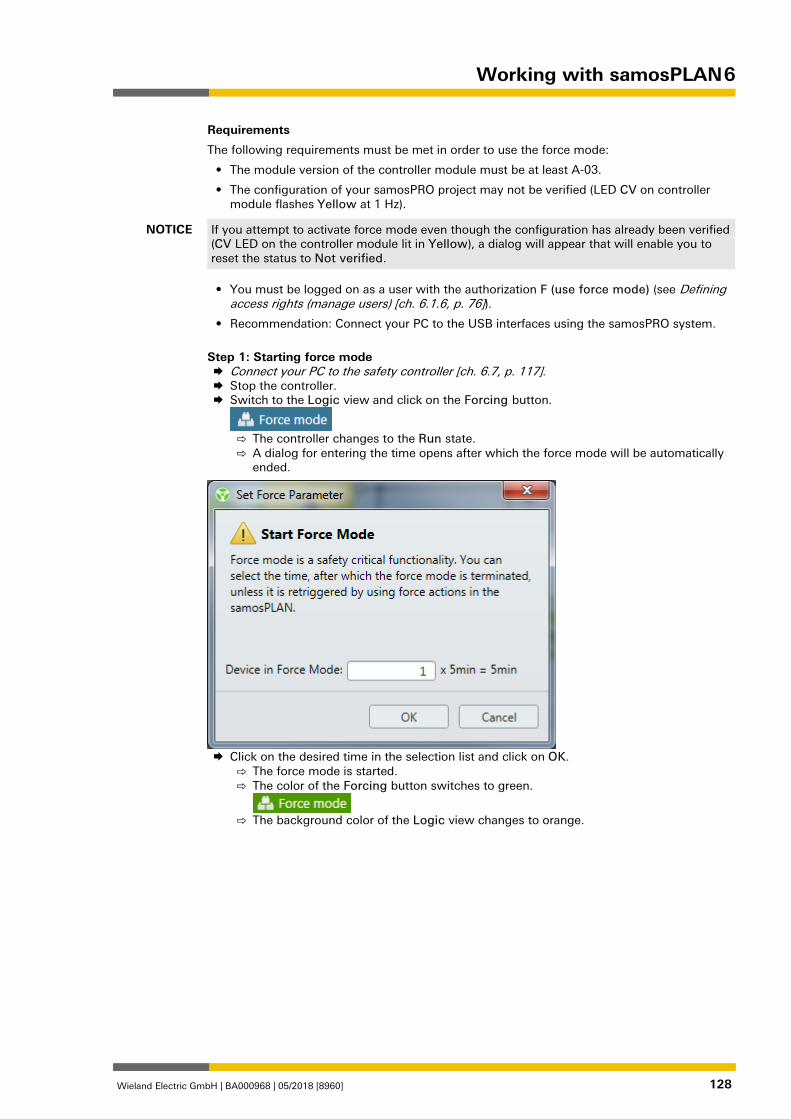
Working with samosPLAN 6
Wieland Electric GmbH | BA000968 | 05/2018 [8960] 128
Requirements
The following requirements must be met in order to use the force mode:
• The module version of the controller module must be at least A-03.
• The configuration of your samosPRO project may not be verified (LED CV on controller module flashes Yellow at 1 Hz).
NOTICE If you attempt to activate force mode even though the configuration has already been verified (CV LED on the controller module lit in Yellow), a dialog will appear that will enable you to reset the status to Not verified.
• You must be logged on as a user with the authorization F (use force mode) (see Defining access rights (manage users) [ch. 6.1.6, p. 76]).
• Recommendation: Connect your PC to the USB interfaces using the samosPRO system.
Step 1: Starting force mode Connect your PC to the safety controller [ch. 6.7, p. 117]. Stop the controller. Switch to the Logic view and click on the Forcing button.
⇨ The controller changes to the Run state. ⇨ A dialog for entering the time opens after which the force mode will be automatically
ended.
Click on the desired time in the selection list and click on OK.
⇨ The force mode is started. ⇨ The color of the Forcing button switches to green.
⇨ The background color of the Logic view changes to orange.
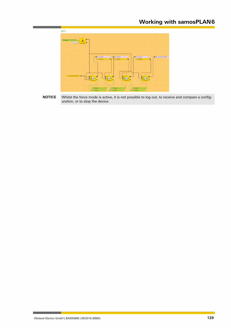
Working with samosPLAN 6
Wieland Electric GmbH | BA000968 | 05/2018 [8960] 129
NOTICE Whilst the force mode is active, it is not possible to log out, to receive and compare a config-uration, or to stop the device.
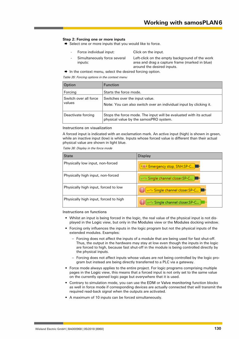
Working with samosPLAN 6
Wieland Electric GmbH | BA000968 | 05/2018 [8960] 130
Step 2: Forcing one or more inputs Select one or more inputs that you would like to force.
- Force individual input: Click on the input.
- Simultaneously force several inputs:
Left-click on the empty background of the work area and drag a capture frame (marked in blue) around the desired inputs.
In the context menu, select the desired forcing option.
Table 35: Forcing options in the context menu
Option Function
Forcing Starts the force mode.
Switch over all force values
Switches over the input value.
Note: You can also switch over an individual input by clicking it.
Deactivate forcing
Stops the force mode. The input will be evaluated with its actual physical value by the samosPRO system.
Instructions on visualization
A forced input is indicated with an exclamation mark. An active input (high) is shown in green, while an inactive input (low) is white. Inputs whose forced value is different than their actual physical value are shown in light blue.
Table 36: Display in the force mode
State Display
Physically low input, non-forced
Physically high input, non-forced
Physically high input, forced to low
Physically high input, forced to high
Instructions on functions
• Whilst an input is being forced in the logic, the real value of the physical input is not dis-played in the Logic view, but only in the Modules view or the Modules docking window.
• Forcing only influences the inputs in the logic program but not the physical inputs of the extended modules. Examples:
– Forcing does not affect the inputs of a module that are being used for fast shut-off. Thus, the output in the hardware may stay at low even though the inputs in the logic are forced to high, because fast shut-off in the module is being controlled directly by the physical inputs.
– Forcing does not affect inputs whose values are not being controlled by the logic pro-gram but instead are being directly transferred to a PLC via a gateway.
• Force mode always applies to the entire project. For logic programs comprising multiple pages in the Logic view, this means that a forced input is not only set to the same value on the currently opened logic page but everywhere that it is used.
• Contrary to simulation mode, you can use the EDM or Valve monitoring function blocks as well in force mode if corresponding devices are actually connected that will transmit the required read-back signal when the outputs are activated.
• A maximum of 10 inputs can be forced simultaneously.
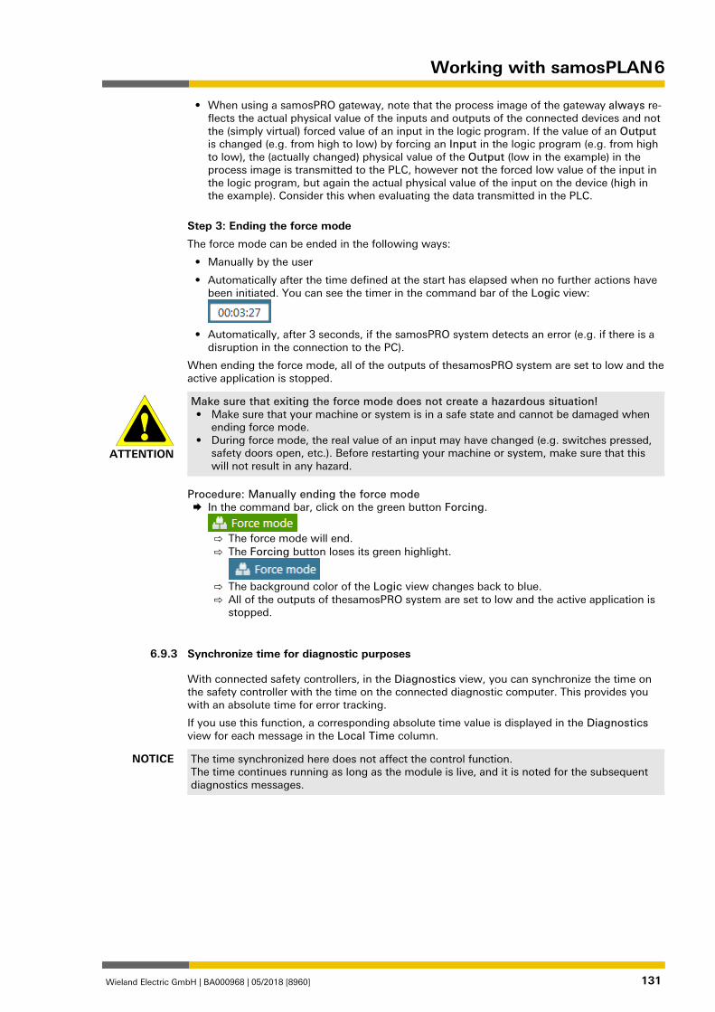
Working with samosPLAN 6
Wieland Electric GmbH | BA000968 | 05/2018 [8960] 131
• When using a samosPRO gateway, note that the process image of the gateway always re-flects the actual physical value of the inputs and outputs of the connected devices and not the (simply virtual) forced value of an input in the logic program. If the value of an Output is changed (e.g. from high to low) by forcing an Input in the logic program (e.g. from high to low), the (actually changed) physical value of the Output (low in the example) in the process image is transmitted to the PLC, however not the forced low value of the input in the logic program, but again the actual physical value of the input on the device (high in the example). Consider this when evaluating the data transmitted in the PLC.
Step 3: Ending the force mode
The force mode can be ended in the following ways:
• Manually by the user
• Automatically after the time defined at the start has elapsed when no further actions have been initiated. You can see the timer in the command bar of the Logic view:
• Automatically, after 3 seconds, if the samosPRO system detects an error (e.g. if there is a
disruption in the connection to the PC).
When ending the force mode, all of the outputs of thesamosPRO system are set to low and the active application is stopped.
ATTENTION
Make sure that exiting the force mode does not create a hazardous situation! • Make sure that your machine or system is in a safe state and cannot be damaged when
ending force mode. • During force mode, the real value of an input may have changed (e.g. switches pressed,
safety doors open, etc.). Before restarting your machine or system, make sure that this will not result in any hazard.
Procedure: Manually ending the force mode In the command bar, click on the green button Forcing.
⇨ The force mode will end. ⇨ The Forcing button loses its green highlight.
⇨ The background color of the Logic view changes back to blue. ⇨ All of the outputs of thesamosPRO system are set to low and the active application is
stopped.
Synchronize time for diagnostic purposes 958691595
With connected safety controllers, in the Diagnostics view, you can synchronize the time on the safety controller with the time on the connected diagnostic computer. This provides you with an absolute time for error tracking.
If you use this function, a corresponding absolute time value is displayed in the Diagnostics view for each message in the Local Time column.
NOTICE The time synchronized here does not affect the control function. The time continues running as long as the module is live, and it is noted for the subsequent diagnostics messages.
6.9.3
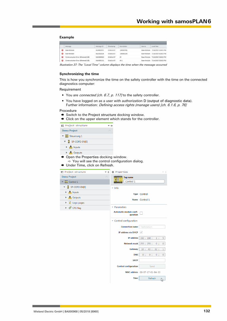
Working with samosPLAN 6
Wieland Electric GmbH | BA000968 | 05/2018 [8960] 132
Example
Illustration 37: The "Local Time" column displays the time when the message occurred
Synchronizing the time
This is how you synchronize the time on the safety controller with the time on the connected diagnostics computer:
Requirement
• You are connected [ch. 6.7, p. 117] to the safety controller.
• You have logged on as a user with authorization D (output of diagnostic data). Further information: Defining access rights (manage users) [ch. 6.1.6, p. 76]
Procedure Switch to the Project structure docking window. Click on the upper element which stands for the controller.
Open the Properties docking window.
⇨ You will see the control configuration dialog. Under Time, click on Refresh.
Referencing the function blocks
Wieland Electric GmbH | BA000968 | 05/2018 [8960] 133
Referencing the function blocks 839395083
General safety information regarding logic programming 839409419
The functional logic of the samosPRO system is programmed with the assistance of function blocks. These function blocks are certified for use in safety-relevant functions when all safety standards are being maintained during implementation. The following sections provide infor-mation on the important aspects of using function blocks in the samosPRO system.
ATTENTION
Be aware of the corresponding standards and safety regulations! All of the safety-related parts of the system (wiring, connected sensors and control devices, configuration) must meet the respective standards (e.g. EN 62061 or EN ISO 13849-1) and safety regulations. Safety-relevant signals must be used for safety-input and safety-output signals in safety-relevant applications. Make sure that the application meets all of the appli-cable standards and regulations. You are responsible for checking that the correct signal sources are being used for these function blocks and that the entire implementation of the safety logic meets the applicable standards and regulations. Always check the function of the samosPRO hardware and logic program in order to ensure that they are behaving according to your risk reduction strategy.
ATTENTION
Implement additional safety measures if the safety value could lead to a hazardous state. The safety value for process data and outputs is low and is set if an error is determined. If the safety value (signal = low) could lead to a hazard-inducing state in the application, additional measures must be implemented, such as evaluation of the status of the process data and switch-off of the output signals in question, if the status evaluation detects an error. This applies particularly to inputs with edge detection.
ATTENTION
Pay particular attention to unexpected rising or falling edges. Particular care must be taken during the planning of applications in which an unexpected rising or falling edge could lead to a hazard-inducing situation at an input with edge detec-tion. An error at an input can generate such types of edges (e.g. interruption in network communication, cable break at a digital input, short-circuit at a digital input that is connected to a test output). The safe value is set until the conditions have been met for resetting the error. For this reason, the signal in question may behave as follows: • It temporarily switches to high instead of remaining in the error-free low state (falling
edge and rising edge, i.e. transition from low to high to low), or • It temporarily switches to low instead of remaining in the error-free high state (falling
edge and rising edge, i.e. transition from high to low to high), or • It remains low instead of changing to the error-free state to high.
ATTENTION
Note the delays from the CPU flag in the reverse path. A reverse path signal is an input signal that is connected at the output of a function block with the same or a higher function block index (the function block index is displayed at the top in each function block). Thus, the input uses the output value of the prior logic cycle. This must be considered for the functionality and particularly when calculating the response time. In order to connect a reverse path signal, you have to use a CPU flag. A CPU flag generally causes a delay of a logic cycle (see below: Example).
7
7.1
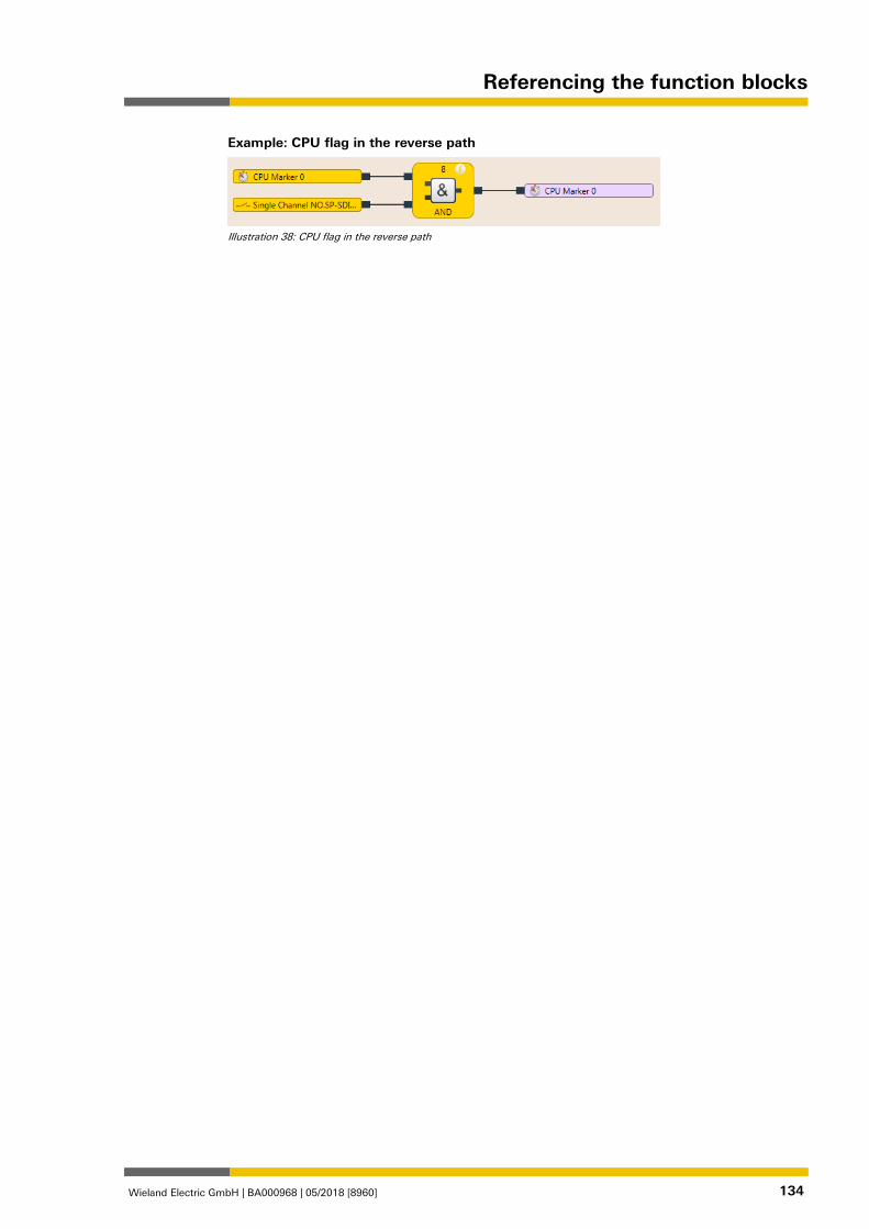
Referencing the function blocks
Wieland Electric GmbH | BA000968 | 05/2018 [8960] 134
Example: CPU flag in the reverse path
Illustration 38: CPU flag in the reverse path
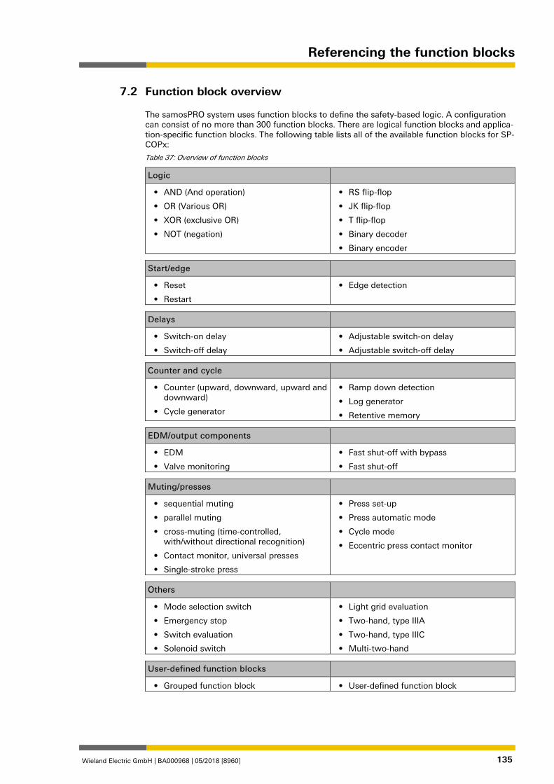
Referencing the function blocks
Wieland Electric GmbH | BA000968 | 05/2018 [8960] 135
Function block overview 839413771
The samosPRO system uses function blocks to define the safety-based logic. A configuration can consist of no more than 300 function blocks. There are logical function blocks and applica-tion-specific function blocks. The following table lists all of the available function blocks for SP-COPx:
Table 37: Overview of function blocks
Logic
• AND (And operation)
• OR (Various OR)
• XOR (exclusive OR)
• NOT (negation)
• RS flip-flop
• JK flip-flop
• T flip-flop
• Binary decoder
• Binary encoder
Start/edge
• Reset
• Restart
• Edge detection
Delays
• Switch-on delay
• Switch-off delay
• Adjustable switch-on delay
• Adjustable switch-off delay
Counter and cycle
• Counter (upward, downward, upward and downward)
• Cycle generator
• Ramp down detection
• Log generator
• Retentive memory
EDM/output components
• EDM
• Valve monitoring
• Fast shut-off with bypass
• Fast shut-off
Muting/presses
• sequential muting
• parallel muting
• cross-muting (time-controlled, with/without directional recognition)
• Contact monitor, universal presses
• Single-stroke press
• Press set-up
• Press automatic mode
• Cycle mode
• Eccentric press contact monitor
Others
• Mode selection switch
• Emergency stop
• Switch evaluation
• Solenoid switch
• Light grid evaluation
• Two-hand, type IIIA
• Two-hand, type IIIC
• Multi-two-hand
User-defined function blocks
• Grouped function block • User-defined function block
7.2

Referencing the function blocks
Wieland Electric GmbH | BA000968 | 05/2018 [8960] 136
The samosPRO system can support up to 300 function blocks in a given application. The re-sponse time is influenced by the number of function blocks. Therefore, you should keep the number function blocks in your application as low as possible.
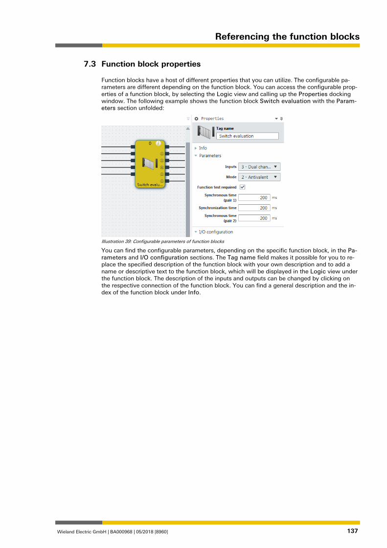
Referencing the function blocks
Wieland Electric GmbH | BA000968 | 05/2018 [8960] 137
Function block properties 839415307
Function blocks have a host of different properties that you can utilize. The configurable pa-rameters are different depending on the function block. You can access the configurable prop-erties of a function block, by selecting the Logic view and calling up the Properties docking window. The following example shows the function block Switch evaluation with the Param-eters section unfolded:
Illustration 39: Configurable parameters of function blocks
You can find the configurable parameters, depending on the specific function block, in the Pa-rameters and I/O configuration sections. The Tag name field makes it possible for you to re-place the specified description of the function block with your own description and to add a name or descriptive text to the function block, which will be displayed in the Logic view under the function block. The description of the inputs and outputs can be changed by clicking on the respective connection of the function block. You can find a general description and the in-dex of the function block under Info.
7.3
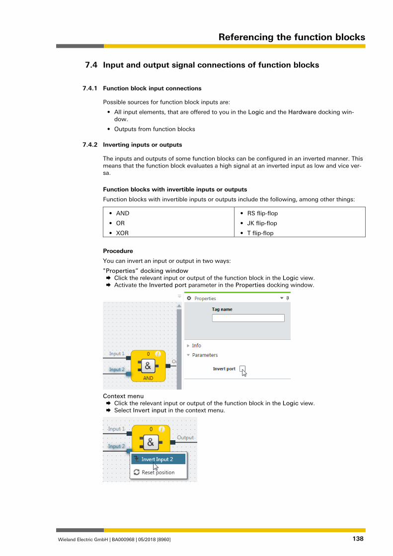
Referencing the function blocks
Wieland Electric GmbH | BA000968 | 05/2018 [8960] 138
Input and output signal connections of function blocks 840958219
Function block input connections 840960651
Possible sources for function block inputs are:
• All input elements, that are offered to you in the Logic and the Hardware docking win-dow.
• Outputs from function blocks
Inverting inputs or outputs 840962571
The inputs and outputs of some function blocks can be configured in an inverted manner. This means that the function block evaluates a high signal at an inverted input as low and vice ver-sa.
Function blocks with invertible inputs or outputs
Function blocks with invertible inputs or outputs include the following, among other things:
• AND
• OR
• XOR
• RS flip-flop
• JK flip-flop
• T flip-flop
Procedure
You can invert an input or output in two ways:
"Properties” docking window Click the relevant input or output of the function block in the Logic view. Activate the Inverted port parameter in the Properties docking window.
Context menu Click the relevant input or output of the function block in the Logic view. Select Invert input in the context menu.
7.4
7.4.1
7.4.2
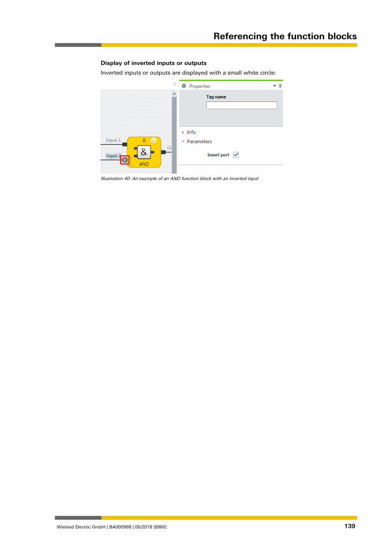
Referencing the function blocks
Wieland Electric GmbH | BA000968 | 05/2018 [8960] 139
Display of inverted inputs or outputs
Inverted inputs or outputs are displayed with a small white circle:
Illustration 40: An example of an AND function block with an inverted input
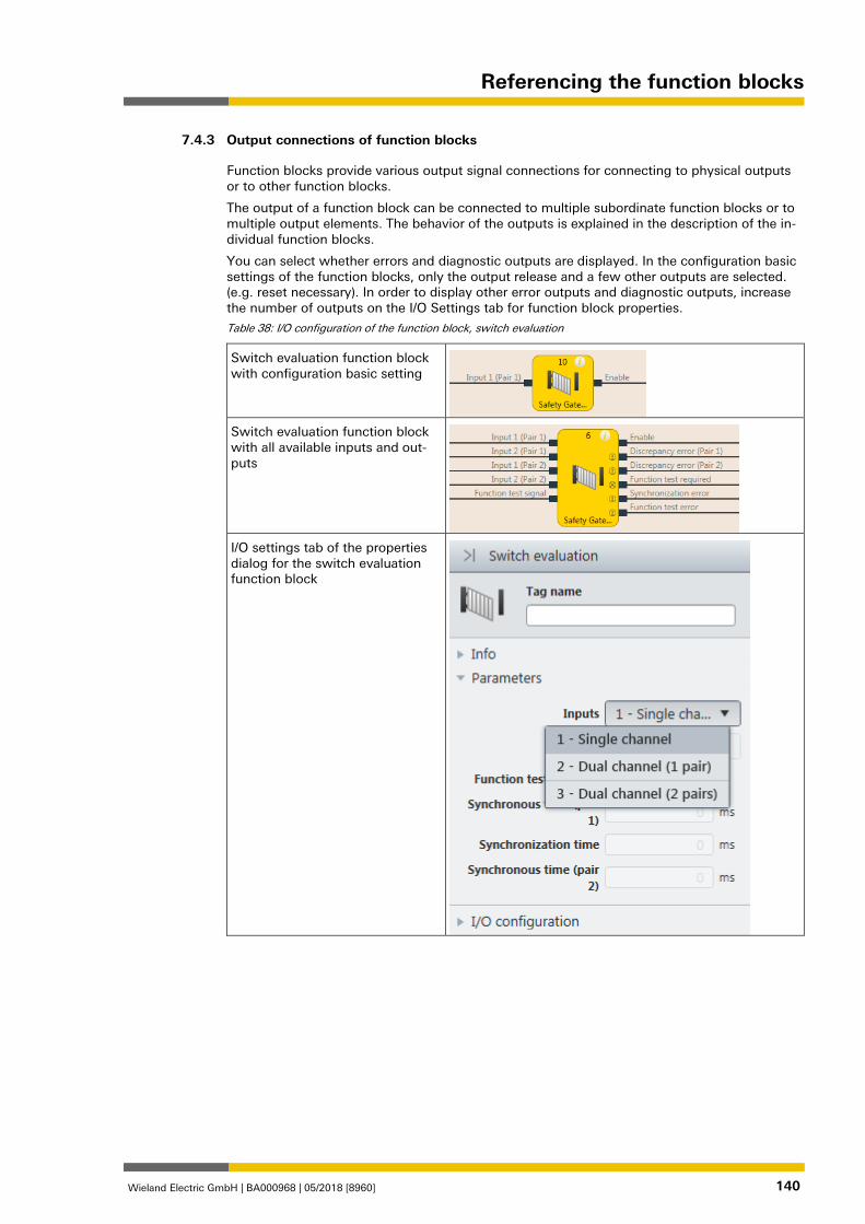
Referencing the function blocks
Wieland Electric GmbH | BA000968 | 05/2018 [8960] 140
Output connections of function blocks 840964491
Function blocks provide various output signal connections for connecting to physical outputs or to other function blocks.
The output of a function block can be connected to multiple subordinate function blocks or to multiple output elements. The behavior of the outputs is explained in the description of the in-dividual function blocks.
You can select whether errors and diagnostic outputs are displayed. In the configuration basic settings of the function blocks, only the output release and a few other outputs are selected. (e.g. reset necessary). In order to display other error outputs and diagnostic outputs, increase the number of outputs on the I/O Settings tab for function block properties.
Table 38: I/O configuration of the function block, switch evaluation
Switch evaluation function block with configuration basic setting
Switch evaluation function block with all available inputs and out-puts
I/O settings tab of the properties dialog for the switch evaluation function block
7.4.3
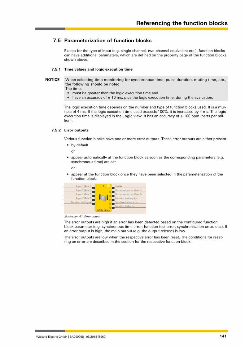
Referencing the function blocks
Wieland Electric GmbH | BA000968 | 05/2018 [8960] 141
Parameterization of function blocks 839424523
Except for the type of input (e.g. single-channel, two-channel equivalent etc.), function blocks can have additional parameters, which are defined on the property page of the function blocks shown above.
Time values and logic execution time 839426059
NOTICE When selecting time monitoring for synchronous time, pulse duration, muting time, etc., the following should be noted The times • must be greater than the logic execution time and • have an accuracy of ± 10 ms, plus the logic execution time, during the evaluation.
The logic execution time depends on the number and type of function blocks used. It is a mul-tiple of 4 ms. If the logic execution time used exceeds 100%, it is increased by 4 ms. The logic execution time is displayed in the Logic view. It has an accuracy of ± 100 ppm (parts per mil-lion).
Error outputs 839427595
Various function blocks have one or more error outputs. These error outputs are either present
• by default
or
• appear automatically at the function block as soon as the corresponding parameters (e.g. synchronous time) are set
or
• appear at the function block once they have been selected in the parameterization of the function block.
Illustration 41: Error output
The error outputs are high if an error has been detected based on the configured function block parameter (e.g. synchronous time error, function test error, synchronization error, etc.). If an error output is high, the main output (e.g. the output release) is low.
The error outputs are low when the respective error has been reset. The conditions for reset-ting an error are described in the section for the respective function block.
7.5
7.5.1
7.5.2
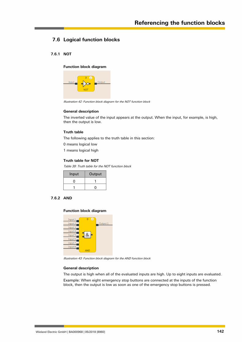
Referencing the function blocks
Wieland Electric GmbH | BA000968 | 05/2018 [8960] 142
Logical function blocks 839430283
NOT 839431819
Function block diagram
Illustration 42: Function block diagram for the NOT function block
General description
The inverted value of the input appears at the output. When the input, for example, is high, then the output is low.
Truth table
The following applies to the truth table in this section:
0 means logical low
1 means logical high
Truth table for NOT Table 39: Truth table for the NOT function block
Input Output
0 1
1 0
AND 839460107
Function block diagram
Illustration 43: Function block diagram for the AND function block
General description
The output is high when all of the evaluated inputs are high. Up to eight inputs are evaluated.
Example: When eight emergency stop buttons are connected at the inputs of the function block, then the output is low as soon as one of the emergency stop buttons is pressed.
7.6
7.6.1
7.6.2
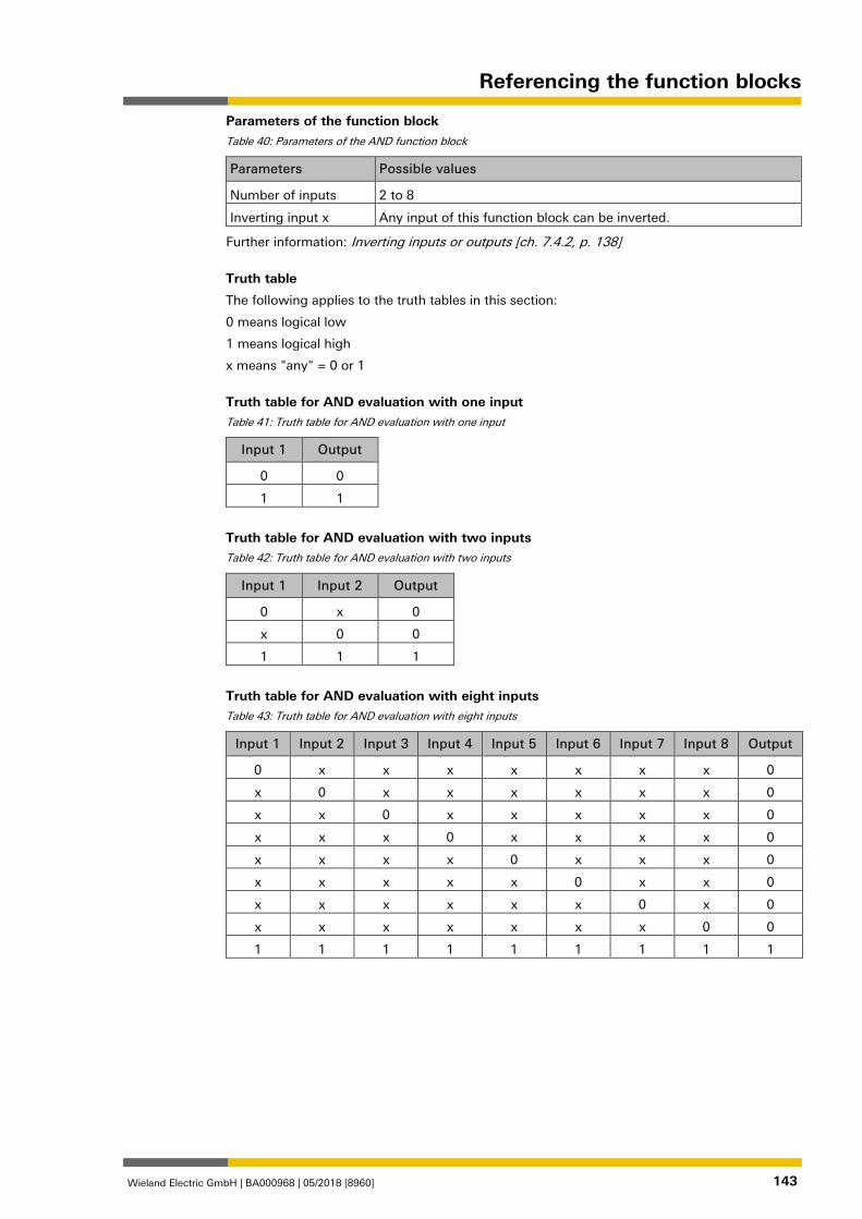
Referencing the function blocks
Wieland Electric GmbH | BA000968 | 05/2018 [8960] 143
Parameters of the function block Table 40: Parameters of the AND function block
Parameters Possible values
Number of inputs 2 to 8
Inverting input x Any input of this function block can be inverted.
Further information: Inverting inputs or outputs [ch. 7.4.2, p. 138]
Truth table
The following applies to the truth tables in this section:
0 means logical low
1 means logical high
x means "any" = 0 or 1
Truth table for AND evaluation with one input Table 41: Truth table for AND evaluation with one input
Input 1 Output
0 0
1 1
Truth table for AND evaluation with two inputs Table 42: Truth table for AND evaluation with two inputs
Input 1 Input 2 Output
0 x 0
x 0 0
1 1 1
Truth table for AND evaluation with eight inputs Table 43: Truth table for AND evaluation with eight inputs
Input 1 Input 2 Input 3 Input 4 Input 5 Input 6 Input 7 Input 8 Output
0 x x x x x x x 0
x 0 x x x x x x 0
x x 0 x x x x x 0
x x x 0 x x x x 0
x x x x 0 x x x 0
x x x x x 0 x x 0
x x x x x x 0 x 0
x x x x x x x 0 0
1 1 1 1 1 1 1 1 1
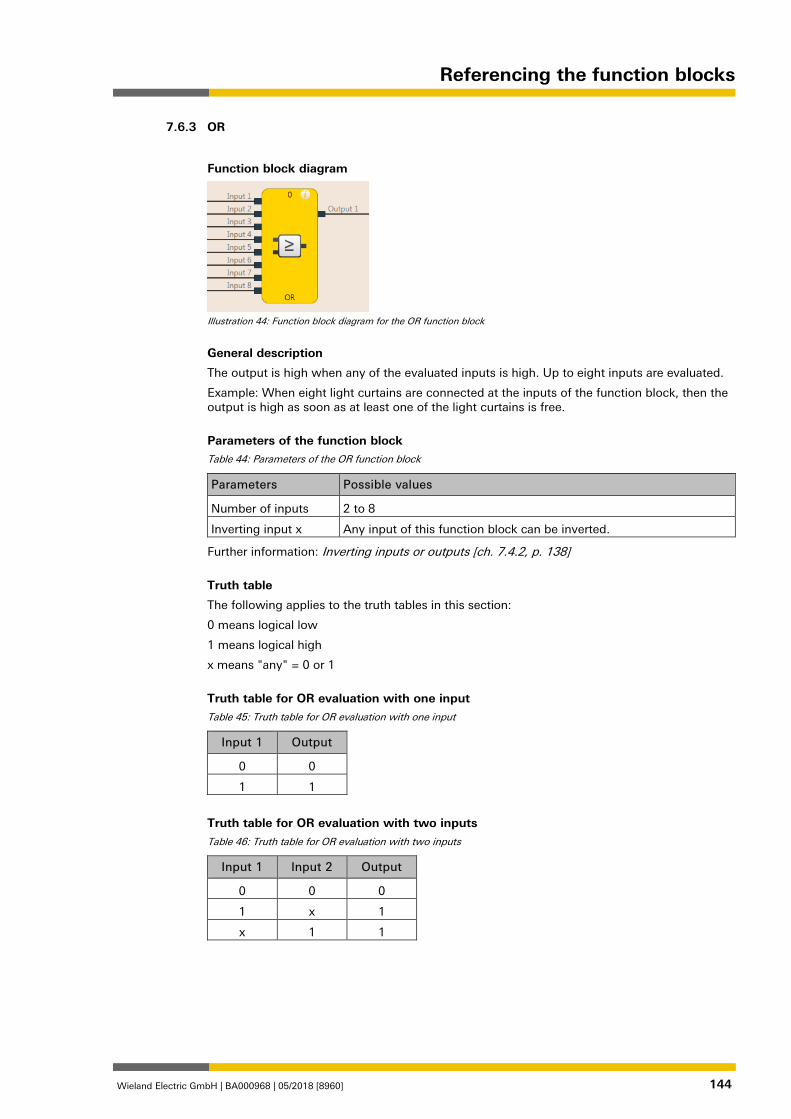
Referencing the function blocks
Wieland Electric GmbH | BA000968 | 05/2018 [8960] 144
OR 839462795
Function block diagram
Illustration 44: Function block diagram for the OR function block
General description
The output is high when any of the evaluated inputs is high. Up to eight inputs are evaluated.
Example: When eight light curtains are connected at the inputs of the function block, then the output is high as soon as at least one of the light curtains is free.
Parameters of the function block Table 44: Parameters of the OR function block
Parameters Possible values
Number of inputs 2 to 8
Inverting input x Any input of this function block can be inverted.
Further information: Inverting inputs or outputs [ch. 7.4.2, p. 138]
Truth table
The following applies to the truth tables in this section:
0 means logical low
1 means logical high
x means "any" = 0 or 1
Truth table for OR evaluation with one input Table 45: Truth table for OR evaluation with one input
Input 1 Output
0 0
1 1
Truth table for OR evaluation with two inputs Table 46: Truth table for OR evaluation with two inputs
Input 1 Input 2 Output
0 0 0
1 x 1
x 1 1
7.6.3
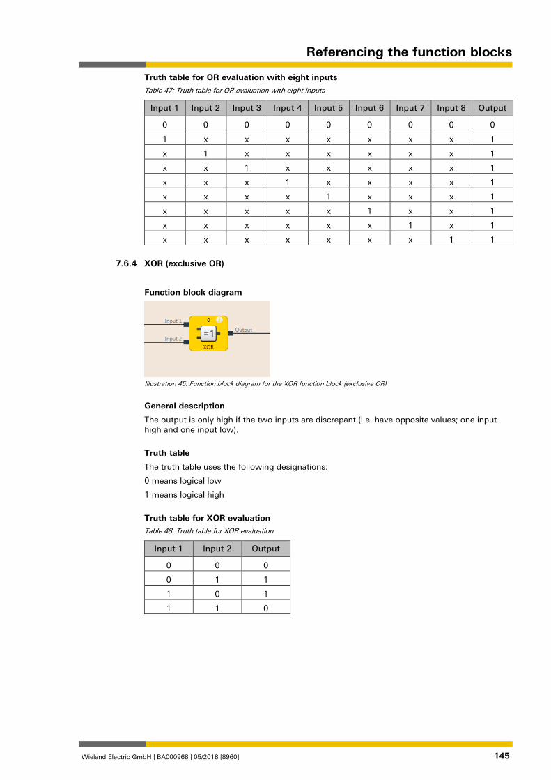
Referencing the function blocks
Wieland Electric GmbH | BA000968 | 05/2018 [8960] 145
Truth table for OR evaluation with eight inputs Table 47: Truth table for OR evaluation with eight inputs
Input 1 Input 2 Input 3 Input 4 Input 5 Input 6 Input 7 Input 8 Output
0 0 0 0 0 0 0 0 0
1 x x x x x x x 1
x 1 x x x x x x 1
x x 1 x x x x x 1
x x x 1 x x x x 1
x x x x 1 x x x 1
x x x x x 1 x x 1
x x x x x x 1 x 1
x x x x x x x 1 1
XOR (exclusive OR) 839465483
Function block diagram
Illustration 45: Function block diagram for the XOR function block (exclusive OR)
General description
The output is only high if the two inputs are discrepant (i.e. have opposite values; one input high and one input low).
Truth table
The truth table uses the following designations:
0 means logical low
1 means logical high
Truth table for XOR evaluation Table 48: Truth table for XOR evaluation
Input 1 Input 2 Output
0 0 0
0 1 1
1 0 1
1 1 0
7.6.4
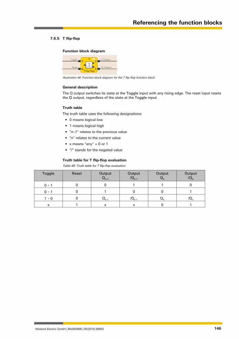
Referencing the function blocks
Wieland Electric GmbH | BA000968 | 05/2018 [8960] 146
T flip-flop 839468171
Function block diagram
Illustration 46: Function block diagram for the T flip-flop function block
General description
The Q output switches its state at the Toggle input with any rising edge. The reset input resets the Q output, regardless of the state at the Toggle input.
Truth table
The truth table uses the following designations:
• 0 means logical low
• 1 means logical high
• "n–1" relates to the previous value
• "n" relates to the current value
• x means "any" = 0 or 1
• "/" stands for the negated value
Truth table for T flip-flop evaluation Table 49: Truth table for T flip-flop evaluation
Toggle Reset Output Qn-1
Output /Qn-1
Output Qn
Output /Qn
0 → 1 0 0 1 1 0
0 → 1 0 1 0 0 1
1 → 0 0 Qn-1 /Qn-1 Qn /Qn
x 1 x x 0 1
7.6.5
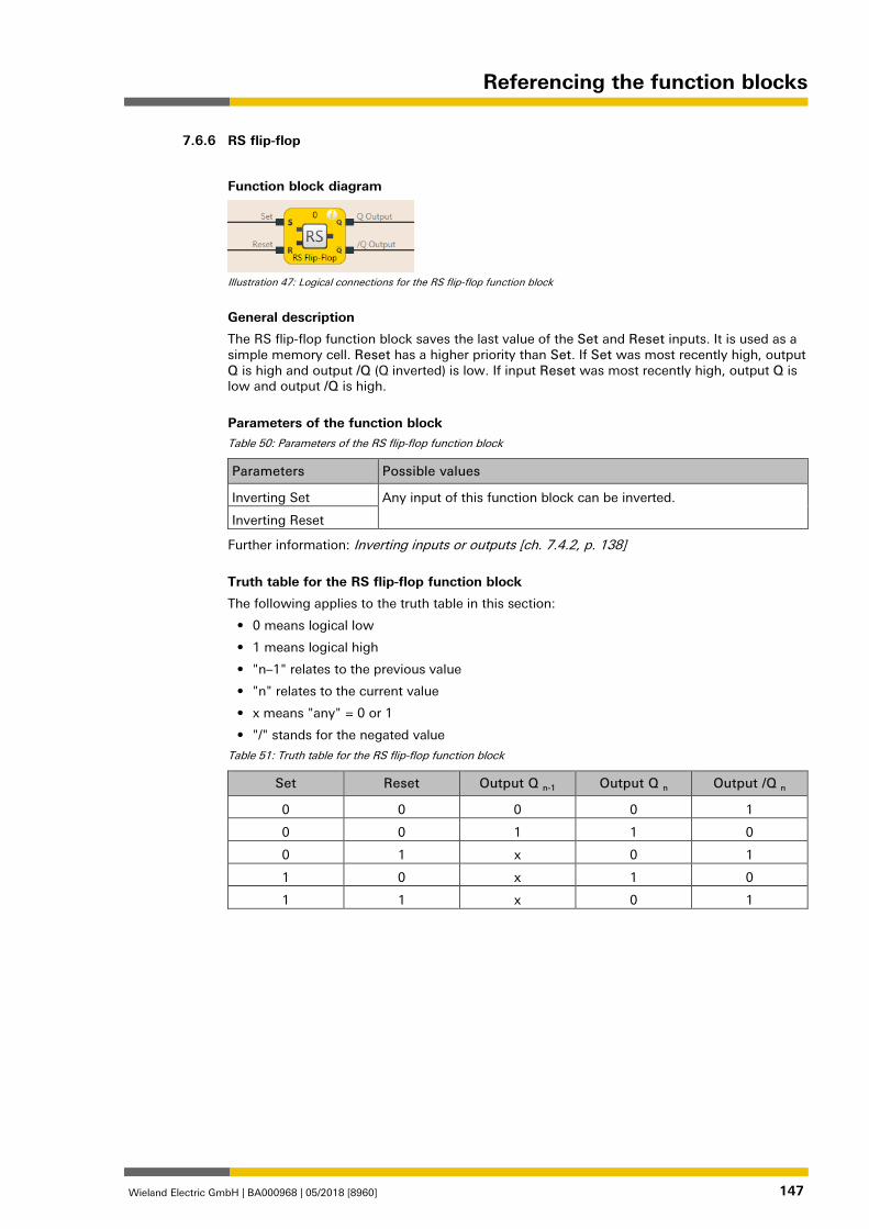
Referencing the function blocks
Wieland Electric GmbH | BA000968 | 05/2018 [8960] 147
RS flip-flop 839470859
Function block diagram
Illustration 47: Logical connections for the RS flip-flop function block
General description
The RS flip-flop function block saves the last value of the Set and Reset inputs. It is used as a simple memory cell. Reset has a higher priority than Set. If Set was most recently high, output Q is high and output /Q (Q inverted) is low. If input Reset was most recently high, output Q is low and output /Q is high.
Parameters of the function block Table 50: Parameters of the RS flip-flop function block
Parameters Possible values
Inverting Set Any input of this function block can be inverted.
Inverting Reset
Further information: Inverting inputs or outputs [ch. 7.4.2, p. 138]
Truth table for the RS flip-flop function block
The following applies to the truth table in this section:
• 0 means logical low
• 1 means logical high
• "n–1" relates to the previous value
• "n" relates to the current value
• x means "any" = 0 or 1
• "/" stands for the negated value
Table 51: Truth table for the RS flip-flop function block
Set Reset Output Q n-1 Output Q n Output /Q n
0 0 0 0 1
0 0 1 1 0
0 1 x 0 1
1 0 x 1 0
1 1 x 0 1
7.6.6
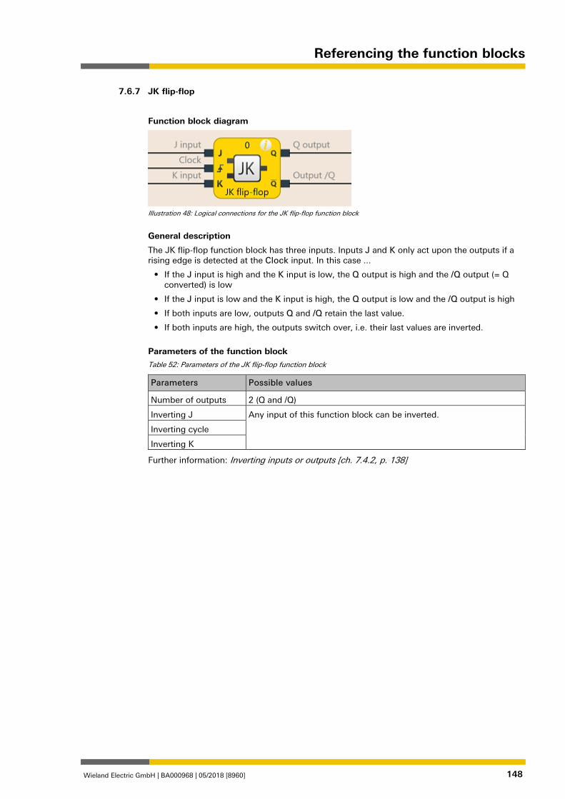
Referencing the function blocks
Wieland Electric GmbH | BA000968 | 05/2018 [8960] 148
JK flip-flop 839473547
Function block diagram
Illustration 48: Logical connections for the JK flip-flop function block
General description
The JK flip-flop function block has three inputs. Inputs J and K only act upon the outputs if a rising edge is detected at the Clock input. In this case ...
• If the J input is high and the K input is low, the Q output is high and the /Q output (= Q converted) is low
• If the J input is low and the K input is high, the Q output is low and the /Q output is high
• If both inputs are low, outputs Q and /Q retain the last value.
• If both inputs are high, the outputs switch over, i.e. their last values are inverted.
Parameters of the function block Table 52: Parameters of the JK flip-flop function block
Parameters Possible values
Number of outputs 2 (Q and /Q)
Inverting J Any input of this function block can be inverted.
Inverting cycle
Inverting K
Further information: Inverting inputs or outputs [ch. 7.4.2, p. 138]
7.6.7
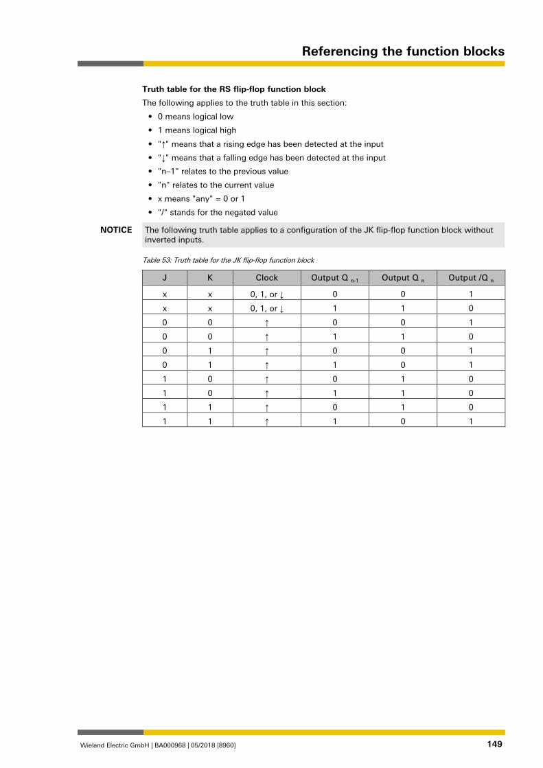
Referencing the function blocks
Wieland Electric GmbH | BA000968 | 05/2018 [8960] 149
Truth table for the RS flip-flop function block
The following applies to the truth table in this section:
• 0 means logical low
• 1 means logical high
• "↑" means that a rising edge has been detected at the input
• "↓" means that a falling edge has been detected at the input
• "n–1" relates to the previous value
• "n" relates to the current value
• x means "any" = 0 or 1
• "/" stands for the negated value
NOTICE The following truth table applies to a configuration of the JK flip-flop function block without inverted inputs.
Table 53: Truth table for the JK flip-flop function block
J K Clock Output Q n-1 Output Q n Output /Q n
x x 0, 1, or ↓ 0 0 1
x x 0, 1, or ↓ 1 1 0
0 0 ↑ 0 0 1
0 0 ↑ 1 1 0
0 1 ↑ 0 0 1
0 1 ↑ 1 0 1
1 0 ↑ 0 1 0
1 0 ↑ 1 1 0
1 1 ↑ 0 1 0
1 1 ↑ 1 0 1
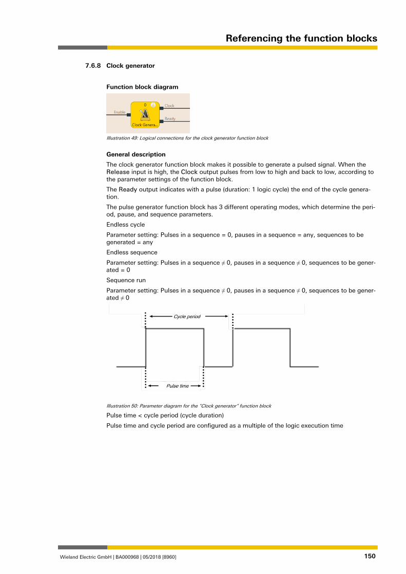
Referencing the function blocks
Wieland Electric GmbH | BA000968 | 05/2018 [8960] 150
Clock generator 839476235
Function block diagram
Illustration 49: Logical connections for the clock generator function block
General description
The clock generator function block makes it possible to generate a pulsed signal. When the Release input is high, the Clock output pulses from low to high and back to low, according to the parameter settings of the function block.
The Ready output indicates with a pulse (duration: 1 logic cycle) the end of the cycle genera-tion.
The pulse generator function block has 3 different operating modes, which determine the peri-od, pause, and sequence parameters.
Endless cycle
Parameter setting: Pulses in a sequence = 0, pauses in a sequence = any, sequences to be generated = any
Endless sequence
Parameter setting: Pulses in a sequence ≠ 0, pauses in a sequence ≠ 0, sequences to be gener-ated = 0
Sequence run
Parameter setting: Pulses in a sequence ≠ 0, pauses in a sequence ≠ 0, sequences to be gener-ated ≠ 0
Illustration 50: Parameter diagram for the "Clock generator" function block
Pulse time < cycle period (cycle duration)
Pulse time and cycle period are configured as a multiple of the logic execution time
7.6.8
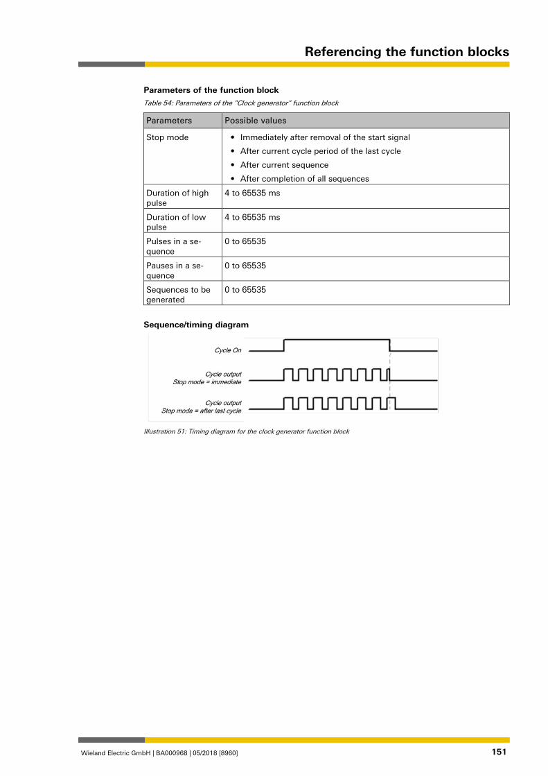
Referencing the function blocks
Wieland Electric GmbH | BA000968 | 05/2018 [8960] 151
Parameters of the function block Table 54: Parameters of the "Clock generator" function block
Parameters Possible values
Stop mode • Immediately after removal of the start signal
• After current cycle period of the last cycle
• After current sequence
• After completion of all sequences
Duration of high pulse
4 to 65535 ms
Duration of low pulse
4 to 65535 ms
Pulses in a se-quence
0 to 65535
Pauses in a se-quence
0 to 65535
Sequences to be generated
0 to 65535
Sequence/timing diagram
Illustration 51: Timing diagram for the clock generator function block
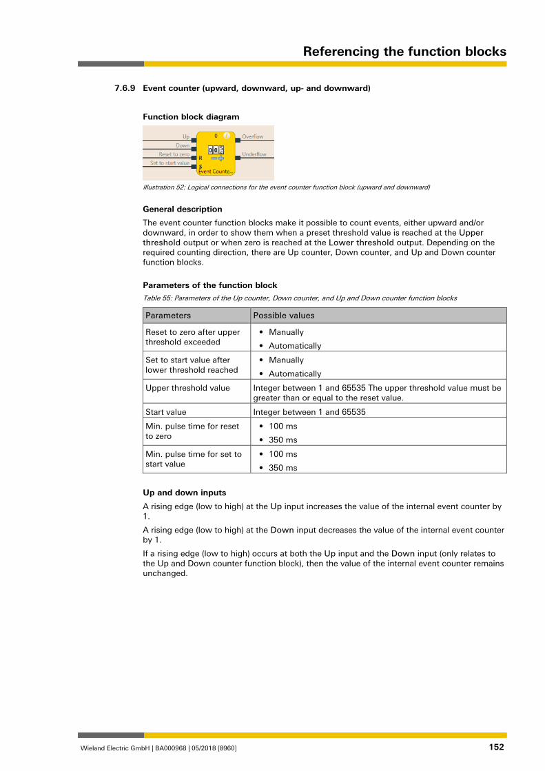
Referencing the function blocks
Wieland Electric GmbH | BA000968 | 05/2018 [8960] 152
Event counter (upward, downward, up- and downward) 839484171
Function block diagram
Illustration 52: Logical connections for the event counter function block (upward and downward)
General description
The event counter function blocks make it possible to count events, either upward and/or downward, in order to show them when a preset threshold value is reached at the Upper threshold output or when zero is reached at the Lower threshold output. Depending on the required counting direction, there are Up counter, Down counter, and Up and Down counter function blocks.
Parameters of the function block Table 55: Parameters of the Up counter, Down counter, and Up and Down counter function blocks
Parameters Possible values
Reset to zero after upper threshold exceeded
• Manually
• Automatically
Set to start value after lower threshold reached
• Manually
• Automatically
Upper threshold value Integer between 1 and 65535 The upper threshold value must be greater than or equal to the reset value.
Start value Integer between 1 and 65535
Min. pulse time for reset to zero
• 100 ms
• 350 ms
Min. pulse time for set to start value
• 100 ms
• 350 ms
Up and down inputs
A rising edge (low to high) at the Up input increases the value of the internal event counter by 1.
A rising edge (low to high) at the Down input decreases the value of the internal event counter by 1.
If a rising edge (low to high) occurs at both the Up input and the Down input (only relates to the Up and Down counter function block), then the value of the internal event counter remains unchanged.
7.6.9
Referencing the function blocks
Wieland Electric GmbH | BA000968 | 05/2018 [8960] 153
Reset to zero
A valid pulse sequence with a transition of low to high to low at the Reset to zero input sets the internal event counter to "0". This occurs regardless of whether the Upper threshold value was reached or not and likewise regardless of whether Reset to zero after upper threshold was configured with the Manual setting or Automatic.
The Minimum pulse time for reset to zero determines the minimum duration of the pulse at the Reset to zero input. Valid values are 100 ms and 350 ms. If the pulse duration is less than the configured minimum pulse time or longer than 30 seconds, then the pulse is ignored.
Set to start value
A valid pulse sequence with a transition from low to high to low at the Set to start value input sets the internal event counter to the configured value of the Start value parameter. This oc-curs regardless of whether Set to start value after lower threshold was configured with Manual setting or Automatic.
The Minimum pulse time for reset to start time determines the minimum duration of the pulse at the Reset to start value input. Valid values are 100 ms and 350 ms. If the pulse dura-tion is less than the configured minimum pulse time or longer than 30 seconds, then the pulse is ignored.
ATTENTION
Make sure that the transitions of the signals for reset to zero and for set to start value meet the requirements. When there is a short-circuit to high (to 24 V DC) at a physical input, the evaluated signal can have a pulse when the signal is reset as a result of short-circuit detection. If this type of pulse can lead to a hazard-inducing state in the machine, then the following points should be not-ed: • Ensure that the cable routing is protected for the signal lines (due to cross-connection
with other signal lines). • No short-circuit detection, i.e. do not reference to test outputs.
Upper threshold value and reset to zero after reaching upper threshold
The Reset to zero after upper threshold parameter determines what occurs when the event counter reaches the Upper threshold value. If this parameter is configured as Automatic and the internal event counter is equal to the Upper threshold value, the Upper threshold output will be at high for the duration of the logic execution time. Following this, the value of the in-ternal event counter will be reset to zero.
When the Reset to zero after upper threshold parameter has been configured as Manual and the Upper threshold value has been reached, the Upper threshold output is set at high and remains on high until the event counter value changes, either through a downward count due to a valid pulse sequence at the Reset to zero input, or due to a valid pulse sequence at the Set at start value input when the start value is less than the upper threshold value. Until then, all of the additional "Upward" count pulses will be ignored.
Start value and set to start value after lower threshold
The Set at start value after lower threshold parameter determines what occurs when the event counter reaches the zero value. If this parameter is configured as Automatic and the in-ternal event counter is equal to zero, the Lower threshold output will be at high for the dura-tion of the logic execution time. Subsequently, the value of the internal event counter will be set at the configured Start value.
If the Set to start value after lower threshold parameter is configured as Manual and the lower limit, i.e. zero, has been reached, the Lower threshold output is set at high and remains on high until the event counter value changes, either due to a count upwards or due to a valid pulse sequence at the Set to start value input. Until then, all of the additional "Downward" count pulses will be ignored.
Truth table for the Up, Down, and Up/Down counter function blocks
The following applies to the truth table in this section:
• 0 means logical low
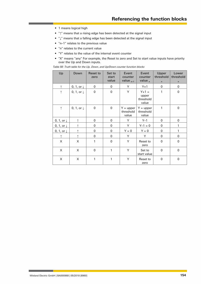
Referencing the function blocks
Wieland Electric GmbH | BA000968 | 05/2018 [8960] 154
• 1 means logical high
• "↑" means that a rising edge has been detected at the signal input
• "↓" means that a falling edge has been detected at the signal input
• "n–1" relates to the previous value
• "n" relates to the current value
• "Y" relates to the value of the internal event counter
• "X" means "any" For example, the Reset to zero and Set to start value inputs have priority over the Up and Down inputs.
Table 56: Truth table for the Up, Down, and Up/Down counter function blocks
Up Down Reset to zero
Set to start value
Event counter value n–1
Event counter value n
Upper threshold
n
Lower threshold
n
↑ 0, 1, or ↓ 0 0 Y Y+1 0 0
↑ 0, 1, or ↓ 0 0 Y Y+1 = upper
threshold value
1 0
↑ 0, 1, or ↓ 0 0 Y = upper threshold
value
Y = upper threshold
value
1 0
0, 1, or ↓ ↑ 0 0 Y Y–1 0 0
0, 1, or ↓ ↑ 0 0 Y Y–1 = 0 0 1
0, 1, or ↓ ↑ 0 0 Y = 0 Y = 0 0 1
↑ ↑ 0 0 Y Y 0 0
X X 1 0 Y Reset to zero
0 0
X X 0 1 Y Set to start value
0 0
X X 1 1 Y Reset to zero
0 0
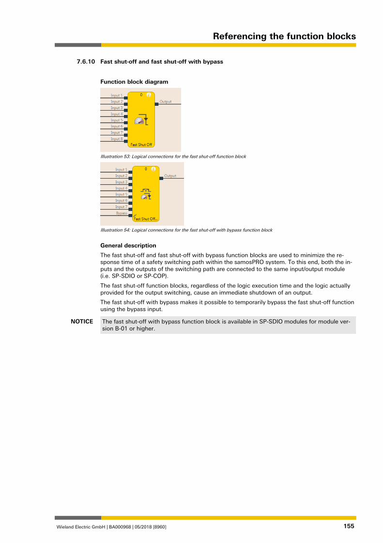
Referencing the function blocks
Wieland Electric GmbH | BA000968 | 05/2018 [8960] 155
Fast shut-off and fast shut-off with bypass 839486859
Function block diagram
Illustration 53: Logical connections for the fast shut-off function block
Illustration 54: Logical connections for the fast shut-off with bypass function block
General description
The fast shut-off and fast shut-off with bypass function blocks are used to minimize the re-sponse time of a safety switching path within the samosPRO system. To this end, both the in-puts and the outputs of the switching path are connected to the same input/output module (i.e. SP-SDIO or SP-COP).
The fast shut-off function blocks, regardless of the logic execution time and the logic actually provided for the output switching, cause an immediate shutdown of an output.
The fast shut-off with bypass makes it possible to temporarily bypass the fast shut-off function using the bypass input.
NOTICE The fast shut-off with bypass function block is available in SP-SDIO modules for module ver-sion B-01 or higher.
7.6.10
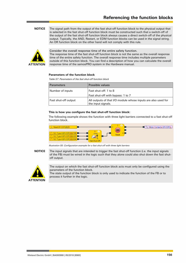
Referencing the function blocks
Wieland Electric GmbH | BA000968 | 05/2018 [8960] 156
NOTICE The signal path from the output of the fast shut-off function block to the physical output that is selected in the fast shut-off function block must be constructed such that a switch-off of the output of the fast shut-off function block always causes a direct switch-off of the physical output. Typically, the AND, Restart, or EDM function blocks can be used in the signal string. An OR function block on the other hand will not comply with this rule.
ATTENTION
Consider the overall response time of the entire safety function. The response time of the fast shut-off function block is not the same as the overall response time of the entire safety function. The overall response time includes multiple parameters outside of this function block. You can find a description of how you can calculate the overall response time of the samosPRO system in the Hardware manual.
Parameters of the function block Table 57: Parameters of the fast shut-off function block
Parameters Possible values
Number of inputs Fast shut-off: 1 to 8
Fast shut-off with bypass: 1 to 7
Fast shut-off output All outputs of that I/O module whose inputs are also used for the input signals.
This is how you configure the fast shut-off function block:
The following example shows the function with three light barriers connected to a fast shut-off function block.
Illustration 55: Configuration example for a fast shut-off with three light barriers
NOTICE The input signals that are intended to trigger the fast shut-off function (i.e. the input signals of the FB) must be wired in the logic such that they alone could also shut down the fast shut-off output.
ATTENTION
The output on which the fast shut-off function block acts must only be configured using the parameters of the function block. The state output of the function block is only used to indicate the function of the FB or to process it further in the logic.
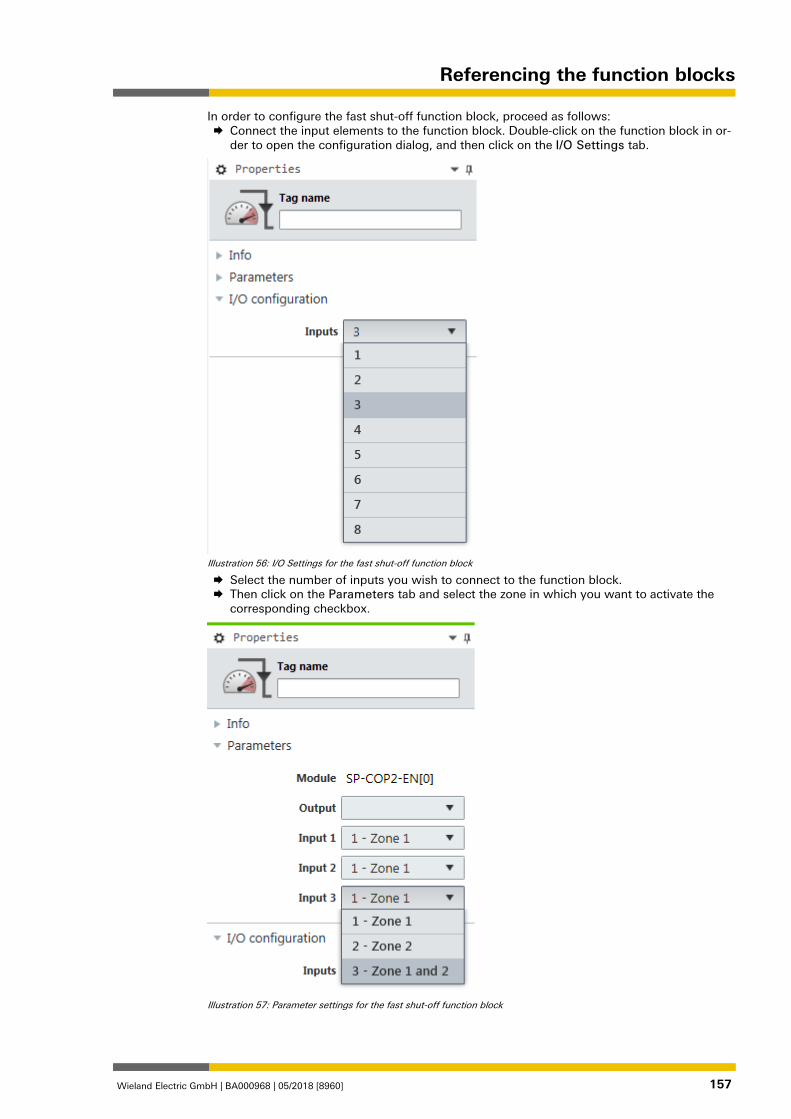
Referencing the function blocks
Wieland Electric GmbH | BA000968 | 05/2018 [8960] 157
In order to configure the fast shut-off function block, proceed as follows: Connect the input elements to the function block. Double-click on the function block in or-
der to open the configuration dialog, and then click on the I/O Settings tab.
Illustration 56: I/O Settings for the fast shut-off function block
Select the number of inputs you wish to connect to the function block. Then click on the Parameters tab and select the zone in which you want to activate the
corresponding checkbox.
Illustration 57: Parameter settings for the fast shut-off function block
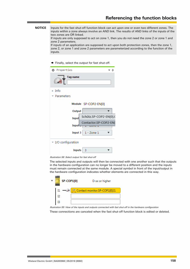
Referencing the function blocks
Wieland Electric GmbH | BA000968 | 05/2018 [8960] 158
NOTICE Inputs for the fast shut-off function block can act upon one or even two different zones. The inputs within a zone always involve an AND link. The results of AND links of the inputs of the two zones are OR linked. If inputs are only supposed to act on zone 1, then you do not need the zone 2 or zone 1 and zone 2 parameters. If inputs of an application are supposed to act upon both protection zones, then the zone 1, zone 2, or zone 1 and zone 2 parameters are parameterized according to the function of the inputs.
Finally, select the output for fast shut-off.
Illustration 58: Select output for fast shut-off
The selected inputs and outputs will then be connected with one another such that the outputs in the hardware configuration can no longer be moved to a different position and the inputs must remain connected at the same module. A special symbol in front of the input/output in the hardware configuration indicates whether elements are connected in this way.
Illustration 59: View of the inputs and outputs connected with fast shut-off in the hardware configuration
These connections are canceled when the fast shut-off function block is edited or deleted.
Referencing the function blocks
Wieland Electric GmbH | BA000968 | 05/2018 [8960] 159
Fast shut-off with bypass
In some applications, it may be necessary to bypass the fast shut-off, for example in a safe setup mode for a machine, in which the machine can only be operated in jog mode. To do this, the fast shut-off with bypass function block is available. It is used and configured precisely as the fast shut-off function block. The only difference is that one of the inputs of the fast shut-off with bypass function block is used for the bypass function. When the Bypass input is high, the fast shut-off with bypass function block is bypassed.
ATTENTION
Make sure that the system or the machine is in a safe state when using the bypass func-tion. As long as the bypass function is active, a stop condition, such as the violation of a protective field, will not lead to a switch-off of the machine. You must ensure that other protective measures are absolutely effective during the bypass, such as the safe setup mode of the machine, so that the machine cannot endanger people or parts of the system during the by-pass.
ATTENTION
Note the longer response time when deactivating the bypass. When the Bypass input is deactivated while a switch-off condition exists, then the outputs will not be switched-off until after the normal response time of the application. The minimum response time for fast shut-off does not apply to the Bypass input. Consider this for your risk analysis and avoidance strategy. Otherwise, there is a hazard for the operator of the machine.
Info
• Contrary to the other inputs and outputs of this function block, the Bypass input can be connected to an output of another function block as well as to any other input element that also can be moved to a different module in the hardware configuration.
• The Bypass input has a switch-on delay of three logic cycles in order to compensate for delays due to the processing time of the logic and the transmission time of the internal safety bus. This delay ensures that the corresponding module has received the bypass sig-nal before it is used for further logic processing in the fast shut-off function block. As a re-sult of this delay, the Bypass input must be at high for three logic cycles beforehand in or-der to bypass the fast shut-off successfully. Once this condition is fulfilled, then the fast shut-off function block output and the physical output at the I/O module will remain at high.
• The fast shut-off directly switches off the output connected to it of the corresponding module while the following logic programming is ignored. Therefore, it is not possible to program additional bypass conditions in the Logic view between the output of the fast shut-off function block and the module output connected to it.
• Note that the value of the connected module output in the online monitor can deviate from the actual value of the physical output of the corresponding module. For example, the connected output may be low due to the following logic, while the output of the fast shut-off function block and the physical output of the module are high because the Bypass in-put is high.
• If your application requires that it be possible to switch off the output of the module inde-pendently of an existing bypass condition (e.g. emergency stop), then the underlying logic must be implemented such that the respective switch-off signal (e.g. emergency stop) also switches off the Bypass input of the function block, as shown in the following example:
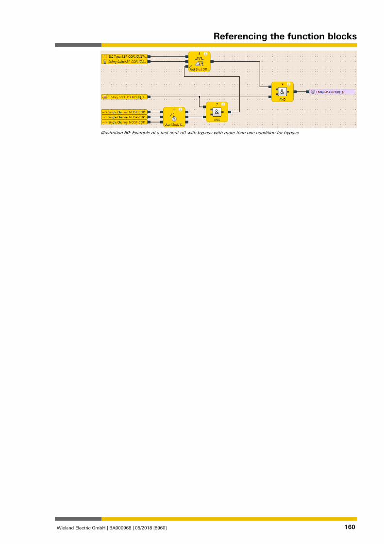
Referencing the function blocks
Wieland Electric GmbH | BA000968 | 05/2018 [8960] 160
Illustration 60: Example of a fast shut-off with bypass with more than one condition for bypass
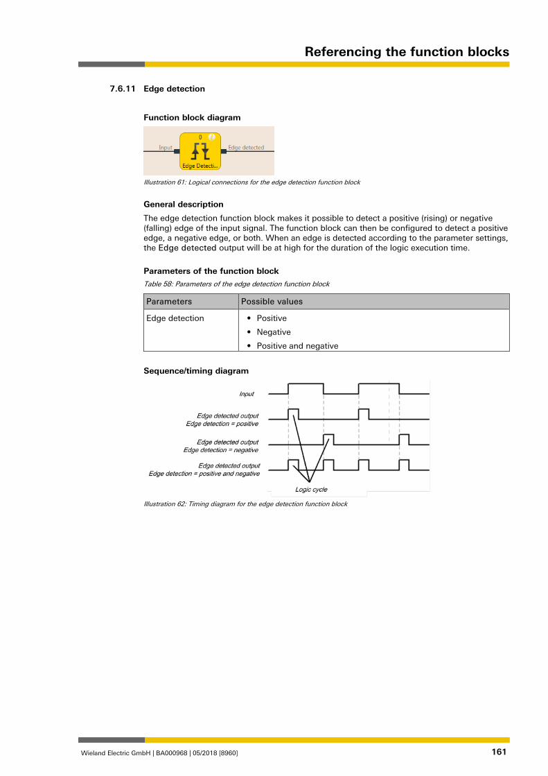
Referencing the function blocks
Wieland Electric GmbH | BA000968 | 05/2018 [8960] 161
Edge detection 839502859
Function block diagram
Illustration 61: Logical connections for the edge detection function block
General description
The edge detection function block makes it possible to detect a positive (rising) or negative (falling) edge of the input signal. The function block can then be configured to detect a positive edge, a negative edge, or both. When an edge is detected according to the parameter settings, the Edge detected output will be at high for the duration of the logic execution time.
Parameters of the function block Table 58: Parameters of the edge detection function block
Parameters Possible values
Edge detection • Positive
• Negative
• Positive and negative
Sequence/timing diagram
Illustration 62: Timing diagram for the edge detection function block
7.6.11
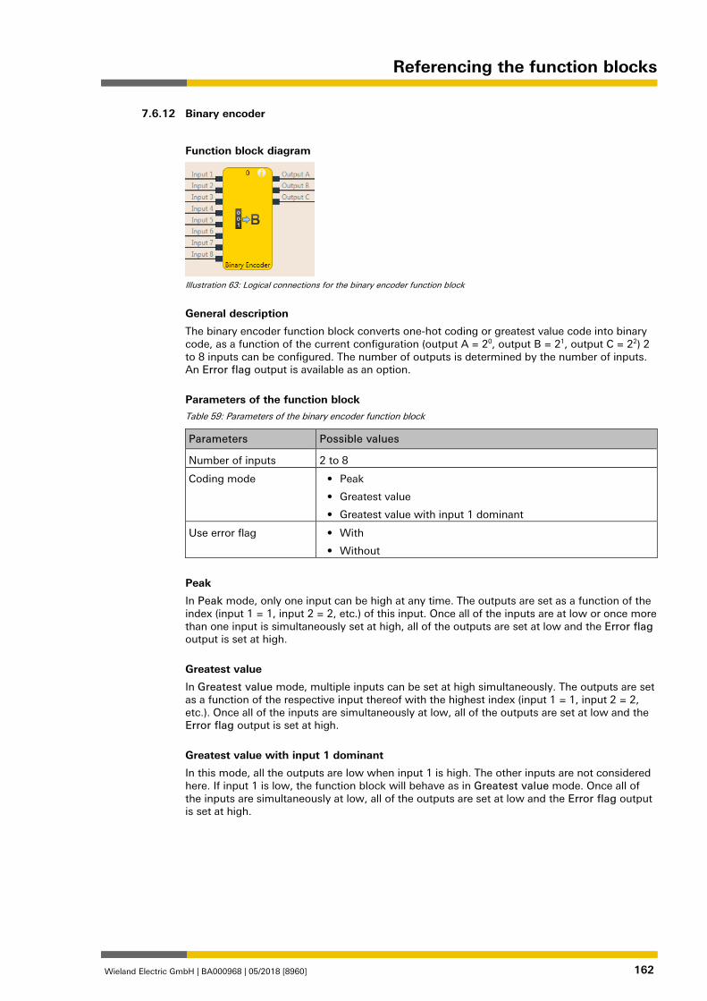
Referencing the function blocks
Wieland Electric GmbH | BA000968 | 05/2018 [8960] 162
Binary encoder 839507211
Function block diagram
Illustration 63: Logical connections for the binary encoder function block
General description
The binary encoder function block converts one-hot coding or greatest value code into binary code, as a function of the current configuration (output A = 20, output B = 21, output C = 22) 2 to 8 inputs can be configured. The number of outputs is determined by the number of inputs. An Error flag output is available as an option.
Parameters of the function block Table 59: Parameters of the binary encoder function block
Parameters Possible values
Number of inputs 2 to 8
Coding mode • Peak
• Greatest value
• Greatest value with input 1 dominant
Use error flag • With
• Without
Peak
In Peak mode, only one input can be high at any time. The outputs are set as a function of the index (input 1 = 1, input 2 = 2, etc.) of this input. Once all of the inputs are at low or once more than one input is simultaneously set at high, all of the outputs are set at low and the Error flag output is set at high.
Greatest value
In Greatest value mode, multiple inputs can be set at high simultaneously. The outputs are set as a function of the respective input thereof with the highest index (input 1 = 1, input 2 = 2, etc.). Once all of the inputs are simultaneously at low, all of the outputs are set at low and the Error flag output is set at high.
Greatest value with input 1 dominant
In this mode, all the outputs are low when input 1 is high. The other inputs are not considered here. If input 1 is low, the function block will behave as in Greatest value mode. Once all of the inputs are simultaneously at low, all of the outputs are set at low and the Error flag output is set at high.
7.6.12
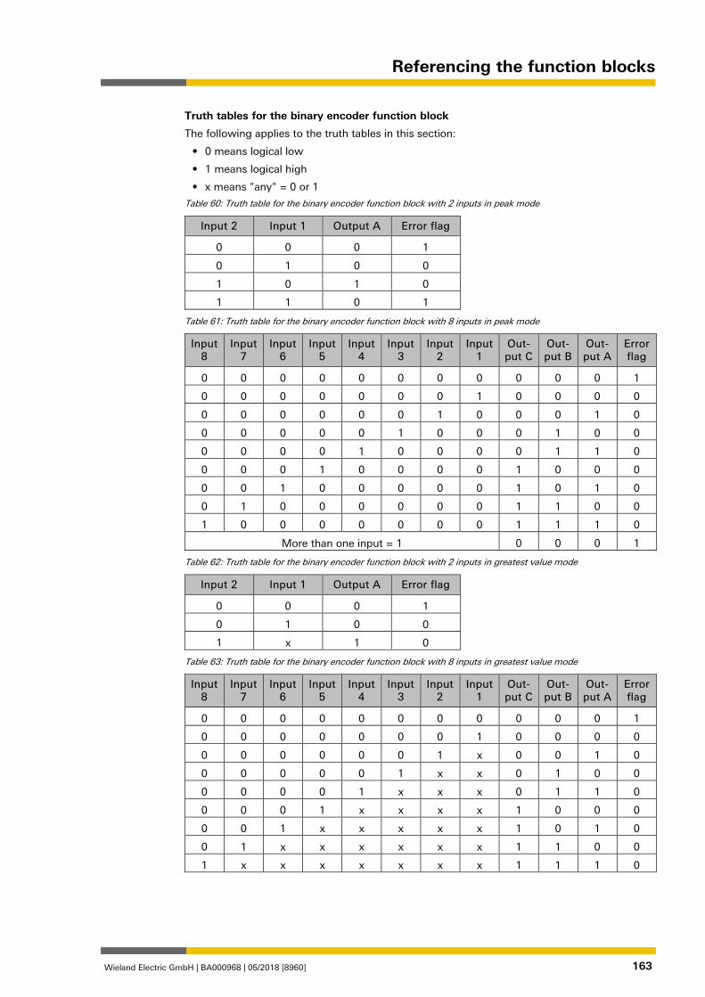
Referencing the function blocks
Wieland Electric GmbH | BA000968 | 05/2018 [8960] 163
Truth tables for the binary encoder function block
The following applies to the truth tables in this section:
• 0 means logical low
• 1 means logical high
• x means "any" = 0 or 1
Table 60: Truth table for the binary encoder function block with 2 inputs in peak mode
Input 2 Input 1 Output A Error flag
0 0 0 1
0 1 0 0
1 0 1 0
1 1 0 1
Table 61: Truth table for the binary encoder function block with 8 inputs in peak mode
Input 8
Input 7
Input 6
Input 5
Input 4
Input 3
Input 2
Input 1
Out-put C
Out-put B
Out-put A
Error flag
0 0 0 0 0 0 0 0 0 0 0 1
0 0 0 0 0 0 0 1 0 0 0 0
0 0 0 0 0 0 1 0 0 0 1 0
0 0 0 0 0 1 0 0 0 1 0 0
0 0 0 0 1 0 0 0 0 1 1 0
0 0 0 1 0 0 0 0 1 0 0 0
0 0 1 0 0 0 0 0 1 0 1 0
0 1 0 0 0 0 0 0 1 1 0 0
1 0 0 0 0 0 0 0 1 1 1 0
More than one input = 1 0 0 0 1
Table 62: Truth table for the binary encoder function block with 2 inputs in greatest value mode
Input 2 Input 1 Output A Error flag
0 0 0 1
0 1 0 0
1 x 1 0
Table 63: Truth table for the binary encoder function block with 8 inputs in greatest value mode
Input 8
Input 7
Input 6
Input 5
Input 4
Input 3
Input 2
Input 1
Out-put C
Out-put B
Out-put A
Error flag
0 0 0 0 0 0 0 0 0 0 0 1
0 0 0 0 0 0 0 1 0 0 0 0
0 0 0 0 0 0 1 x 0 0 1 0
0 0 0 0 0 1 x x 0 1 0 0
0 0 0 0 1 x x x 0 1 1 0
0 0 0 1 x x x x 1 0 0 0
0 0 1 x x x x x 1 0 1 0
0 1 x x x x x x 1 1 0 0
1 x x x x x x x 1 1 1 0
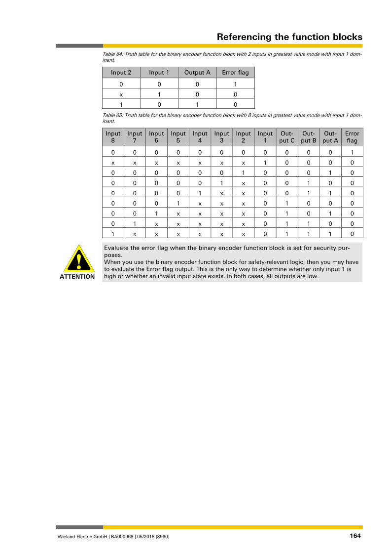
Referencing the function blocks
Wieland Electric GmbH | BA000968 | 05/2018 [8960] 164
Table 64: Truth table for the binary encoder function block with 2 inputs in greatest value mode with input 1 dom-inant.
Input 2 Input 1 Output A Error flag
0 0 0 1
x 1 0 0
1 0 1 0
Table 65: Truth table for the binary encoder function block with 8 inputs in greatest value mode with input 1 dom-inant.
Input 8
Input 7
Input 6
Input 5
Input 4
Input 3
Input 2
Input 1
Out-put C
Out-put B
Out-put A
Error flag
0 0 0 0 0 0 0 0 0 0 0 1
x x x x x x x 1 0 0 0 0
0 0 0 0 0 0 1 0 0 0 1 0
0 0 0 0 0 1 x 0 0 1 0 0
0 0 0 0 1 x x 0 0 1 1 0
0 0 0 1 x x x 0 1 0 0 0
0 0 1 x x x x 0 1 0 1 0
0 1 x x x x x 0 1 1 0 0
1 x x x x x x 0 1 1 1 0
ATTENTION
Evaluate the error flag when the binary encoder function block is set for security pur-poses. When you use the binary encoder function block for safety-relevant logic, then you may have to evaluate the Error flag output. This is the only way to determine whether only input 1 is high or whether an invalid input state exists. In both cases, all outputs are low.
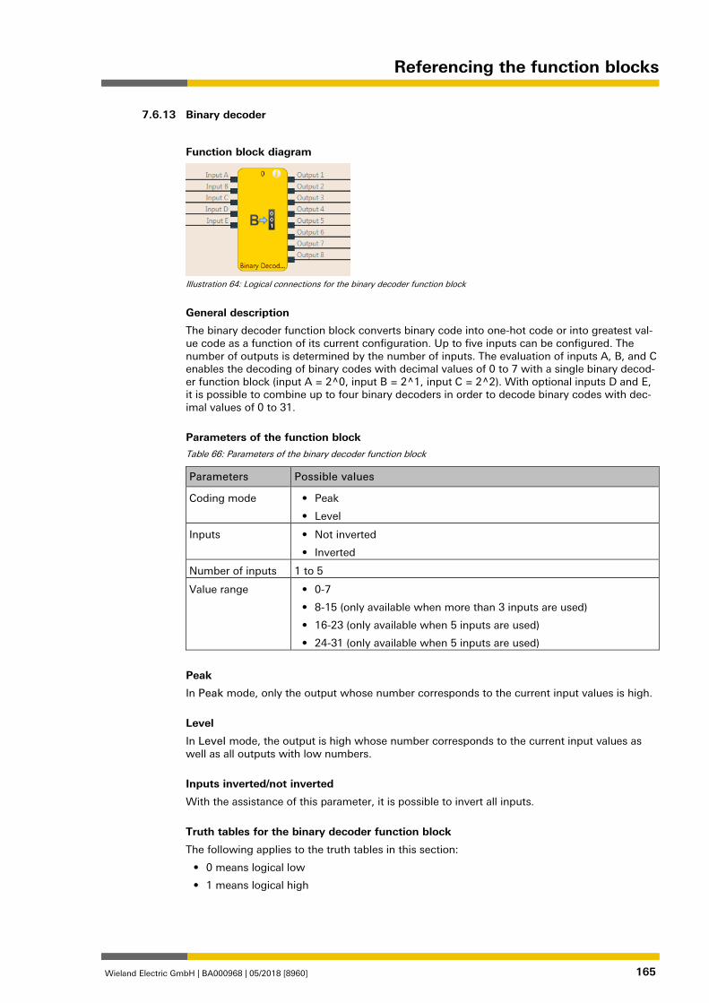
Referencing the function blocks
Wieland Electric GmbH | BA000968 | 05/2018 [8960] 165
Binary decoder 839509899
Function block diagram
Illustration 64: Logical connections for the binary decoder function block
General description
The binary decoder function block converts binary code into one-hot code or into greatest val-ue code as a function of its current configuration. Up to five inputs can be configured. The number of outputs is determined by the number of inputs. The evaluation of inputs A, B, and C enables the decoding of binary codes with decimal values of 0 to 7 with a single binary decod-er function block (input A = 2^0, input B = 2^1, input C = 2^2). With optional inputs D and E, it is possible to combine up to four binary decoders in order to decode binary codes with dec-imal values of 0 to 31.
Parameters of the function block Table 66: Parameters of the binary decoder function block
Parameters Possible values
Coding mode • Peak
• Level
Inputs • Not inverted
• Inverted
Number of inputs 1 to 5
Value range • 0-7
• 8-15 (only available when more than 3 inputs are used)
• 16-23 (only available when 5 inputs are used)
• 24-31 (only available when 5 inputs are used)
Peak
In Peak mode, only the output whose number corresponds to the current input values is high.
Level
In Level mode, the output is high whose number corresponds to the current input values as well as all outputs with low numbers.
Inputs inverted/not inverted
With the assistance of this parameter, it is possible to invert all inputs.
Truth tables for the binary decoder function block
The following applies to the truth tables in this section:
• 0 means logical low
• 1 means logical high
7.6.13
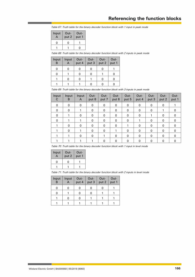
Referencing the function blocks
Wieland Electric GmbH | BA000968 | 05/2018 [8960] 166
Table 67: Truth table for the binary decoder function block with 1 input in peak mode
Input A
Out-put 2
Out-put 1
0 0 1
1 1 0
Table 68: Truth table for the binary decoder function block with 2 inputs in peak mode
Input B
Input A
Out-put 4
Out-put 3
Out-put 2
Out-put 1
0 0 0 0 0 1
0 1 0 0 1 0
1 0 0 1 0 0
1 1 1 0 0 0
Table 69: Truth table for the binary decoder function block with 3 inputs in peak mode
Input C
Input B
Input A
Out-put 8
Out-put 7
Out-put 6
Out-put 5
Out-put 4
Out-put 3
Out-put 2
Out-put 1
0 0 0 0 0 0 0 0 0 0 1
0 0 1 0 0 0 0 0 0 1 0
0 1 0 0 0 0 0 0 1 0 0
0 1 1 0 0 0 0 1 0 0 0
1 0 0 0 0 0 1 0 0 0 0
1 0 1 0 0 1 0 0 0 0 0
1 1 0 0 1 0 0 0 0 0 0
1 1 1 1 0 0 0 0 0 0 0
Table 70: Truth table for the binary decoder function block with 1 input in level mode
Input A
Out-put 2
Out-put 1
0 0 1
1 1 1
Table 71: Truth table for the binary decoder function block with 2 inputs in level mode
Input B
Input A
Out-put 4
Out-put 3
Out-put 2
Out-put 1
0 0 0 0 0 1
0 1 0 0 1 1
1 0 0 1 1 1
1 1 1 1 1 1
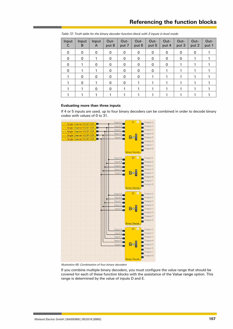
Referencing the function blocks
Wieland Electric GmbH | BA000968 | 05/2018 [8960] 167
Table 72: Truth table for the binary decoder function block with 3 inputs in level mode
Input C
Input B
Input A
Out-put 8
Out-put 7
Out-put 6
Out-put 5
Out-put 4
Out-put 3
Out-put 2
Out-put 1
0 0 0 0 0 0 0 0 0 0 1
0 0 1 0 0 0 0 0 0 1 1
0 1 0 0 0 0 0 0 1 1 1
0 1 1 0 0 0 0 1 1 1 1
1 0 0 0 0 0 1 1 1 1 1
1 0 1 0 0 1 1 1 1 1 1
1 1 0 0 1 1 1 1 1 1 1
1 1 1 1 1 1 1 1 1 1 1
Evaluating more than three inputs
If 4 or 5 inputs are used, up to four binary decoders can be combined in order to decode binary codes with values of 0 to 31.
Illustration 65: Combination of four binary decoders
If you combine multiple binary decoders, you must configure the value range that should be covered for each of these function blocks with the assistance of the Value range option. This range is determined by the value of inputs D and E.
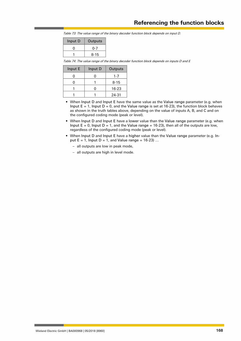
Referencing the function blocks
Wieland Electric GmbH | BA000968 | 05/2018 [8960] 168
Table 73: The value range of the binary decoder function block depends on input D.
Input D Outputs
0 0-7
1 8-15
Table 74: The value range of the binary decoder function block depends on inputs D and E
Input E Input D Outputs
0 0 1-7
0 1 8-15
1 0 16-23
1 1 24-31
• When Input D and Input E have the same value as the Value range parameter (e.g. when Input E = 1, Input D = 0, and the Value range is set at 16-23), the function block behaves as shown in the truth tables above, depending on the value of inputs A, B, and C and on the configured coding mode (peak or level).
• When Input D and Input E have a lower value than the Value range parameter (e.g. when Input E = 0, Input D = 1, and the Value range = 16-23), then all of the outputs are low, regardless of the configured coding mode (peak or level).
• When Input D and Input E have a higher value than the Value range parameter (e.g. In-put E = 1, Input D = 1, and Value range = 16-23) …
– all outputs are low in peak mode,
– all outputs are high in level mode.
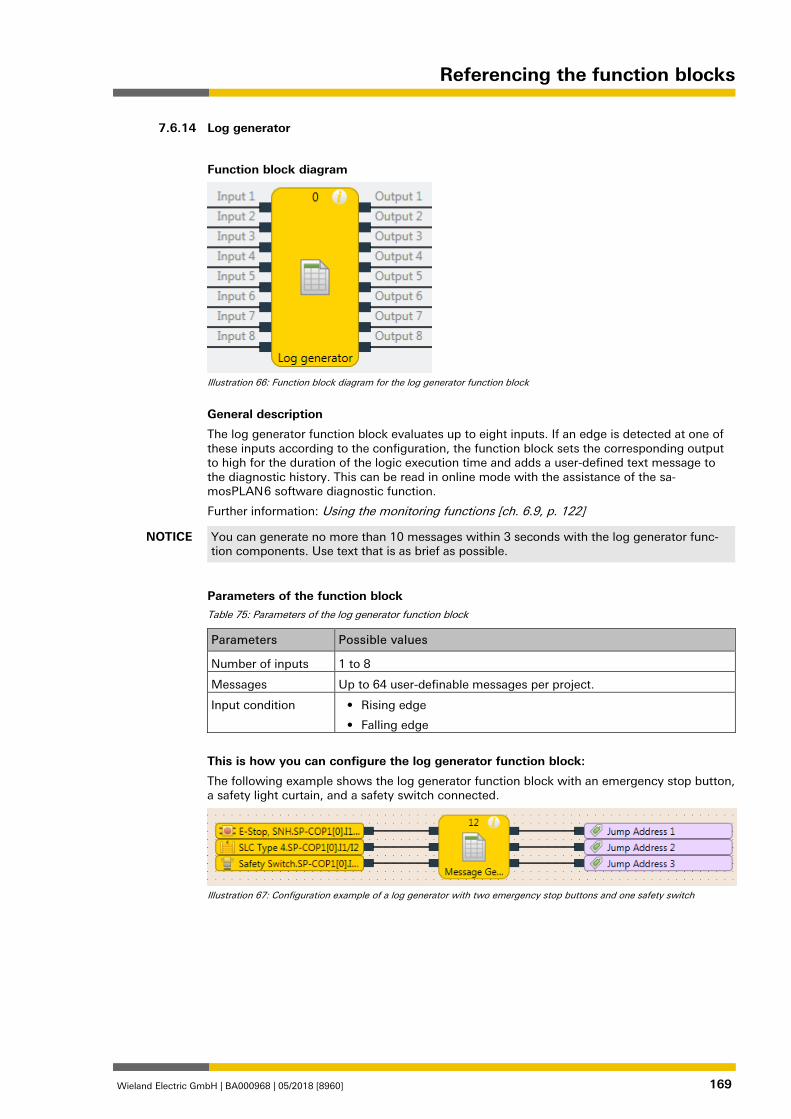
Referencing the function blocks
Wieland Electric GmbH | BA000968 | 05/2018 [8960] 169
Log generator 839514251
Function block diagram
Illustration 66: Function block diagram for the log generator function block
General description
The log generator function block evaluates up to eight inputs. If an edge is detected at one of these inputs according to the configuration, the function block sets the corresponding output to high for the duration of the logic execution time and adds a user-defined text message to the diagnostic history. This can be read in online mode with the assistance of the sa-mosPLAN 6 software diagnostic function.
Further information: Using the monitoring functions [ch. 6.9, p. 122]
NOTICE You can generate no more than 10 messages within 3 seconds with the log generator func-tion components. Use text that is as brief as possible.
Parameters of the function block Table 75: Parameters of the log generator function block
Parameters Possible values
Number of inputs 1 to 8
Messages Up to 64 user-definable messages per project.
Input condition • Rising edge
• Falling edge
This is how you can configure the log generator function block:
The following example shows the log generator function block with an emergency stop button, a safety light curtain, and a safety switch connected.
Illustration 67: Configuration example of a log generator with two emergency stop buttons and one safety switch
7.6.14
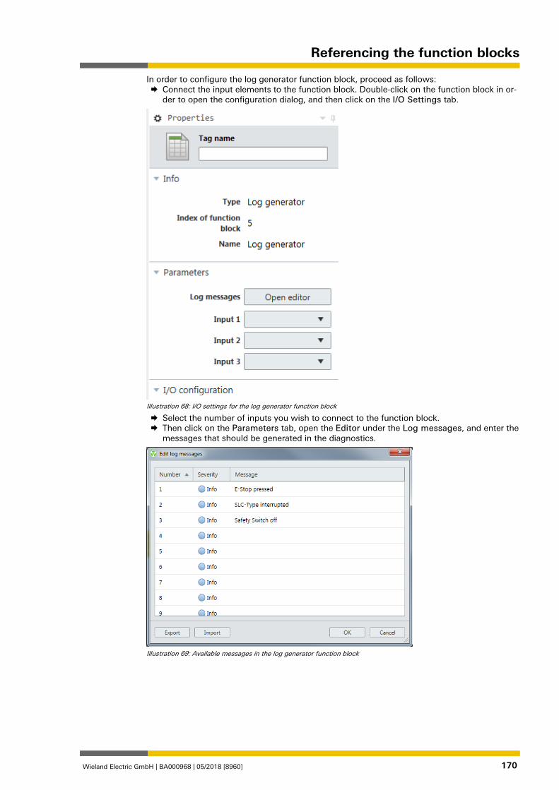
Referencing the function blocks
Wieland Electric GmbH | BA000968 | 05/2018 [8960] 170
In order to configure the log generator function block, proceed as follows: Connect the input elements to the function block. Double-click on the function block in or-
der to open the configuration dialog, and then click on the I/O Settings tab.
Illustration 68: I/O settings for the log generator function block
Select the number of inputs you wish to connect to the function block. Then click on the Parameters tab, open the Editor under the Log messages, and enter the
messages that should be generated in the diagnostics.
Illustration 69: Available messages in the log generator function block
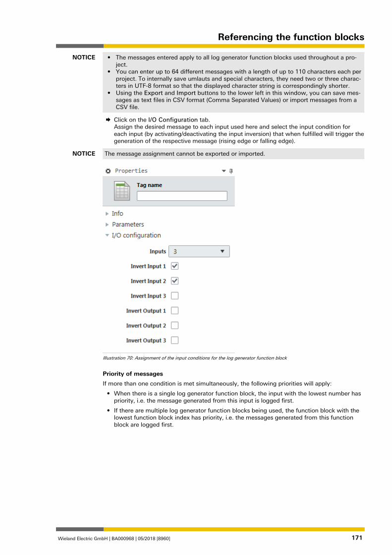
Referencing the function blocks
Wieland Electric GmbH | BA000968 | 05/2018 [8960] 171
NOTICE • The messages entered apply to all log generator function blocks used throughout a pro-ject.
• You can enter up to 64 different messages with a length of up to 110 characters each per project. To internally save umlauts and special characters, they need two or three charac-ters in UTF-8 format so that the displayed character string is correspondingly shorter.
• Using the Export and Import buttons to the lower left in this window, you can save mes-sages as text files in CSV format (Comma Separated Values) or import messages from a CSV file.
Click on the I/O Configuration tab. Assign the desired message to each input used here and select the input condition for each input (by activating/deactivating the input inversion) that when fulfilled will trigger the generation of the respective message (rising edge or falling edge).
NOTICE The message assignment cannot be exported or imported.
Illustration 70: Assignment of the input conditions for the log generator function block
Priority of messages
If more than one condition is met simultaneously, the following priorities will apply:
• When there is a single log generator function block, the input with the lowest number has priority, i.e. the message generated from this input is logged first.
• If there are multiple log generator function blocks being used, the function block with the lowest function block index has priority, i.e. the messages generated from this function block are logged first.
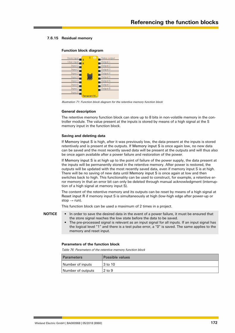
Referencing the function blocks
Wieland Electric GmbH | BA000968 | 05/2018 [8960] 172
Residual memory 839523595
Function block diagram
Illustration 71: Function block diagram for the retentive memory function block
General description
The retentive memory function block can store up to 8 bits in non-volatile memory in the con-troller module. The value present at the inputs is stored by means of a high signal at the S memory input in the function block.
Saving and deleting data
If Memory input S is high, after it was previously low, the data present at the inputs is stored retentively and is present at the outputs. If Memory input S is once again low, no new data can be saved and the most recently saved data will be present at the outputs and will thus also be once again available after a power failure and restoration of the power.
If Memory input S is at high up to the point of failure of the power supply, the data present at the inputs will be permanently stored in the retentive memory. After power is restored, the outputs will be updated with the most recently saved data, even if memory input S is at high. There will be no saving of new data until Memory input S is once again at low and then switches back to high. This functionality can be used to construct, for example, a retentive er-ror memory in that an error bit can only be deleted through manual acknowledgment (interrup-tion of a high signal at memory input S).
The content of the retentive memory and its outputs can be reset by means of a high signal at Reset input R if memory input S is simultaneously at high (low-high edge after power-up or stop → run).
This function block can be used a maximum of 2 times in a project.
NOTICE • In order to save the desired data in the event of a power failure, it must be ensured that the store signal reaches the low state before the data to be saved.
• The pre-processed signal is relevant as an input signal for all inputs. If an input signal has the logical level "1" and there is a test pulse error, a "0" is saved. The same applies to the memory and reset input.
Parameters of the function block Table 76: Parameters of the retentive memory function block
Parameters Possible values
Number of inputs 3 to 10
Number of outputs 2 to 9
7.6.15
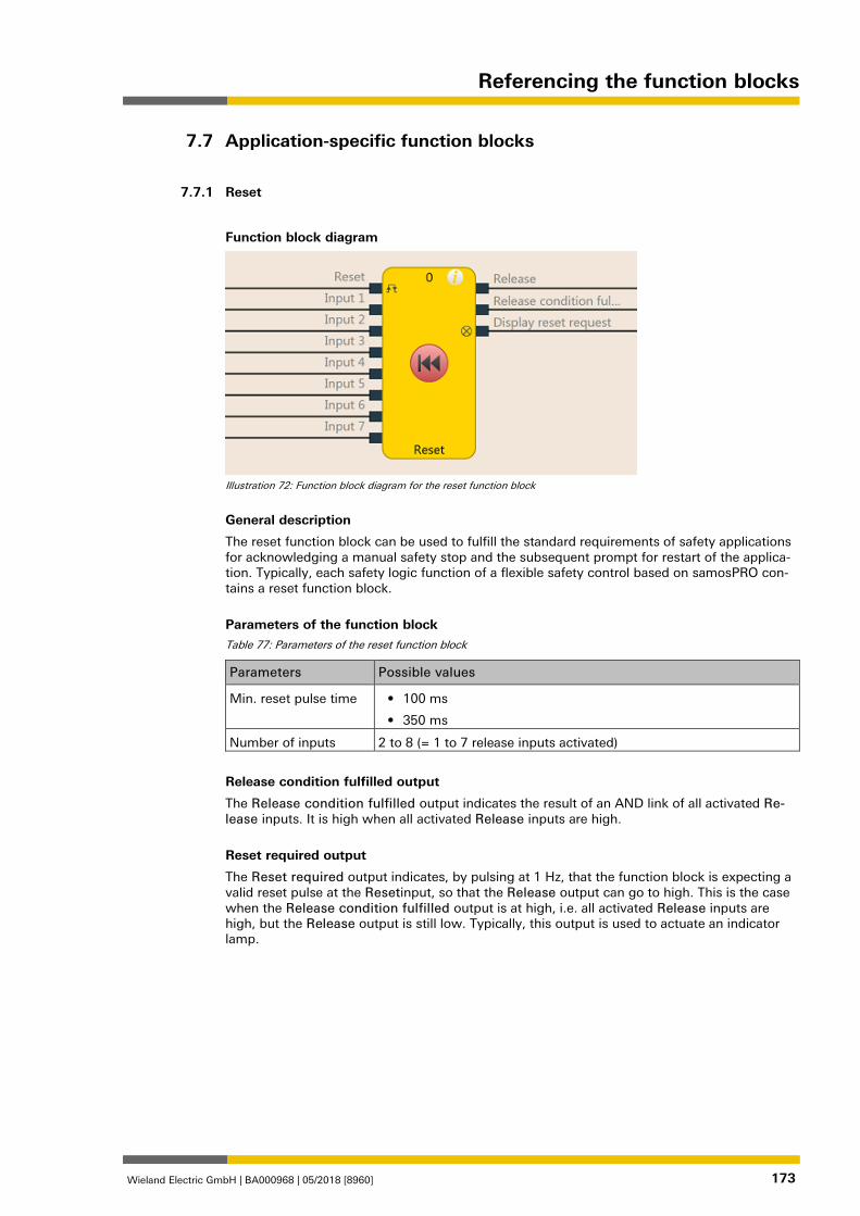
Referencing the function blocks
Wieland Electric GmbH | BA000968 | 05/2018 [8960] 173
Application-specific function blocks 839556363
Reset 839557899
Function block diagram
Illustration 72: Function block diagram for the reset function block
General description
The reset function block can be used to fulfill the standard requirements of safety applications for acknowledging a manual safety stop and the subsequent prompt for restart of the applica-tion. Typically, each safety logic function of a flexible safety control based on samosPRO con-tains a reset function block.
Parameters of the function block Table 77: Parameters of the reset function block
Parameters Possible values
Min. reset pulse time • 100 ms
• 350 ms
Number of inputs 2 to 8 (= 1 to 7 release inputs activated)
Release condition fulfilled output
The Release condition fulfilled output indicates the result of an AND link of all activated Re-lease inputs. It is high when all activated Release inputs are high.
Reset required output
The Reset required output indicates, by pulsing at 1 Hz, that the function block is expecting a valid reset pulse at the Resetinput, so that the Release output can go to high. This is the case when the Release condition fulfilled output is at high, i.e. all activated Release inputs are high, but the Release output is still low. Typically, this output is used to actuate an indicator lamp.
7.7
7.7.1
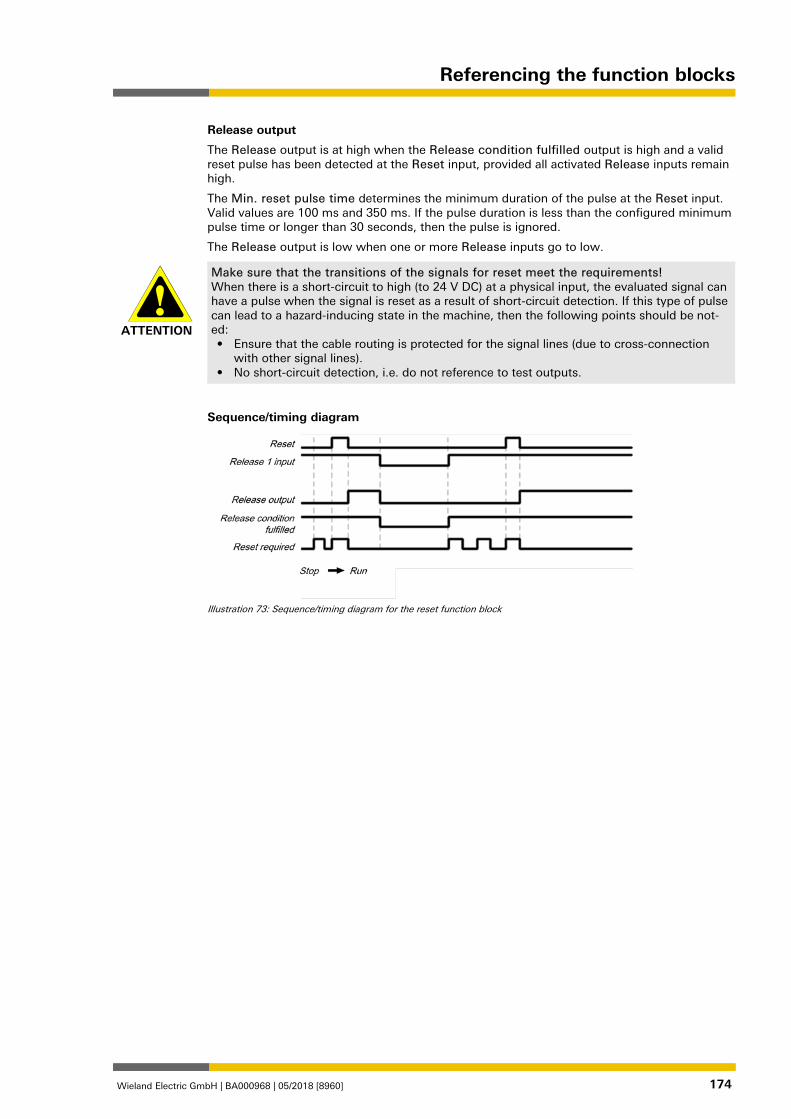
Referencing the function blocks
Wieland Electric GmbH | BA000968 | 05/2018 [8960] 174
Release output
The Release output is at high when the Release condition fulfilled output is high and a valid reset pulse has been detected at the Reset input, provided all activated Release inputs remain high.
The Min. reset pulse time determines the minimum duration of the pulse at the Reset input. Valid values are 100 ms and 350 ms. If the pulse duration is less than the configured minimum pulse time or longer than 30 seconds, then the pulse is ignored.
The Release output is low when one or more Release inputs go to low.
ATTENTION
Make sure that the transitions of the signals for reset meet the requirements! When there is a short-circuit to high (to 24 V DC) at a physical input, the evaluated signal can have a pulse when the signal is reset as a result of short-circuit detection. If this type of pulse can lead to a hazard-inducing state in the machine, then the following points should be not-ed: • Ensure that the cable routing is protected for the signal lines (due to cross-connection
with other signal lines). • No short-circuit detection, i.e. do not reference to test outputs.
Sequence/timing diagram
Illustration 73: Sequence/timing diagram for the reset function block
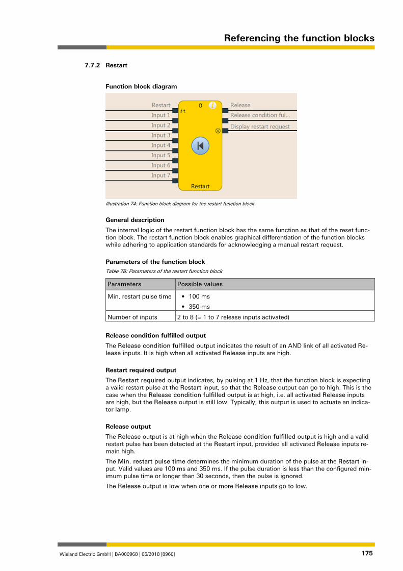
Referencing the function blocks
Wieland Electric GmbH | BA000968 | 05/2018 [8960] 175
Restart 839651851
Function block diagram
Illustration 74: Function block diagram for the restart function block
General description
The internal logic of the restart function block has the same function as that of the reset func-tion block. The restart function block enables graphical differentiation of the function blocks while adhering to application standards for acknowledging a manual restart request.
Parameters of the function block Table 78: Parameters of the restart function block
Parameters Possible values
Min. restart pulse time • 100 ms
• 350 ms
Number of inputs 2 to 8 (= 1 to 7 release inputs activated)
Release condition fulfilled output
The Release condition fulfilled output indicates the result of an AND link of all activated Re-lease inputs. It is high when all activated Release inputs are high.
Restart required output
The Restart required output indicates, by pulsing at 1 Hz, that the function block is expecting a valid restart pulse at the Restart input, so that the Release output can go to high. This is the case when the Release condition fulfilled output is at high, i.e. all activated Release inputs are high, but the Release output is still low. Typically, this output is used to actuate an indica-tor lamp.
Release output
The Release output is at high when the Release condition fulfilled output is high and a valid restart pulse has been detected at the Restart input, provided all activated Release inputs re-main high.
The Min. restart pulse time determines the minimum duration of the pulse at the Restart in-put. Valid values are 100 ms and 350 ms. If the pulse duration is less than the configured min-imum pulse time or longer than 30 seconds, then the pulse is ignored.
The Release output is low when one or more Release inputs go to low.
7.7.2
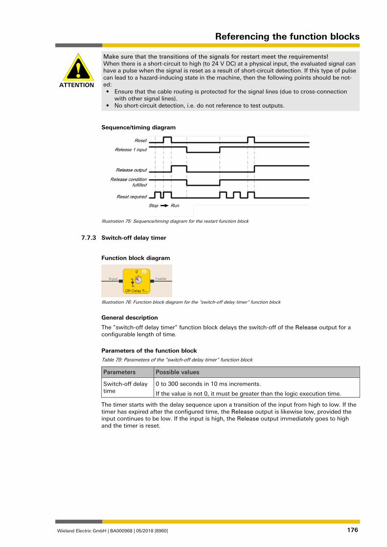
Referencing the function blocks
Wieland Electric GmbH | BA000968 | 05/2018 [8960] 176
ATTENTION
Make sure that the transitions of the signals for restart meet the requirements! When there is a short-circuit to high (to 24 V DC) at a physical input, the evaluated signal can have a pulse when the signal is reset as a result of short-circuit detection. If this type of pulse can lead to a hazard-inducing state in the machine, then the following points should be not-ed: • Ensure that the cable routing is protected for the signal lines (due to cross-connection
with other signal lines). • No short-circuit detection, i.e. do not reference to test outputs.
Sequence/timing diagram
Illustration 75: Sequence/timing diagram for the restart function block
Switch-off delay timer 839656203
Function block diagram
Illustration 76: Function block diagram for the "switch-off delay timer" function block
General description
The "switch-off delay timer" function block delays the switch-off of the Release output for a configurable length of time.
Parameters of the function block Table 79: Parameters of the "switch-off delay timer" function block
Parameters Possible values
Switch-off delay time
0 to 300 seconds in 10 ms increments.
If the value is not 0, it must be greater than the logic execution time.
The timer starts with the delay sequence upon a transition of the input from high to low. If the timer has expired after the configured time, the Release output is likewise low, provided the input continues to be low. If the input is high, the Release output immediately goes to high and the timer is reset.
7.7.3
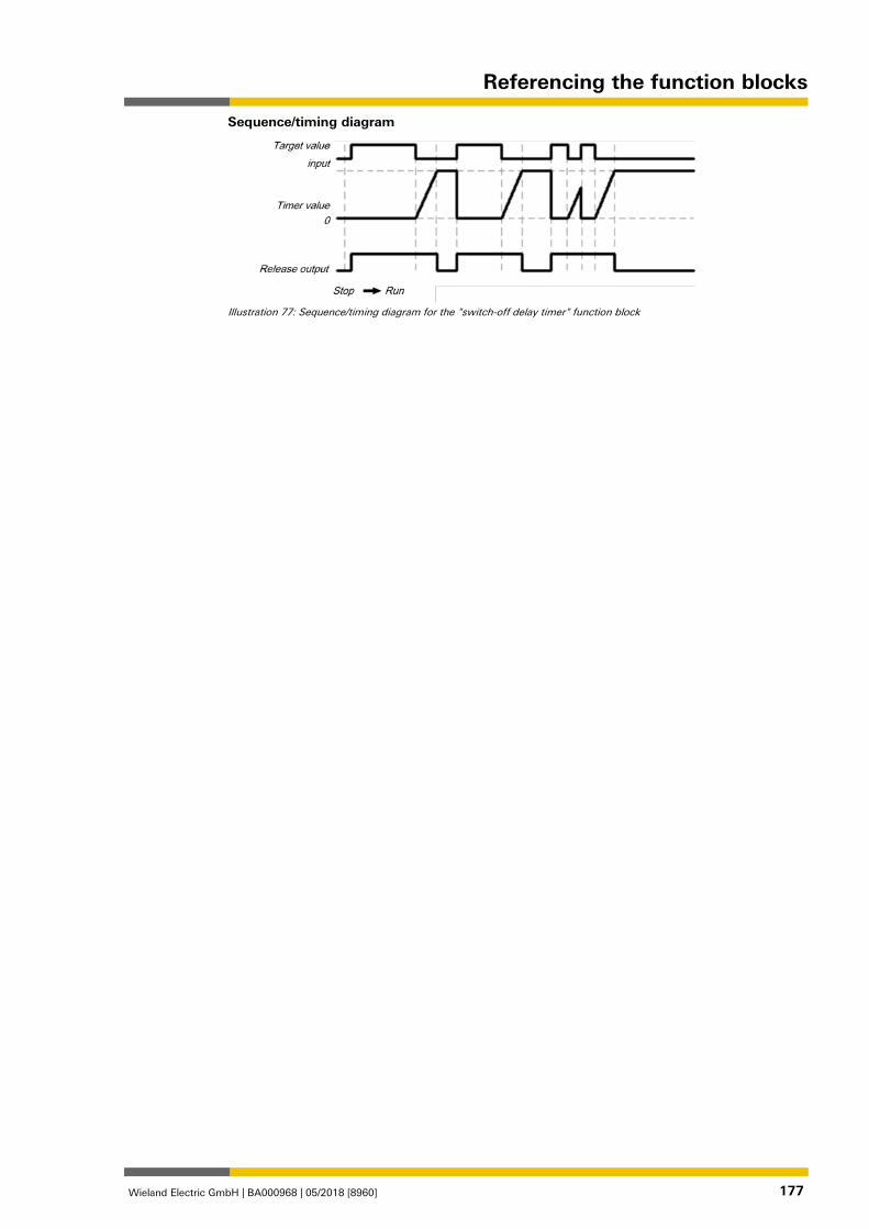
Referencing the function blocks
Wieland Electric GmbH | BA000968 | 05/2018 [8960] 177
Sequence/timing diagram
Illustration 77: Sequence/timing diagram for the "switch-off delay timer" function block
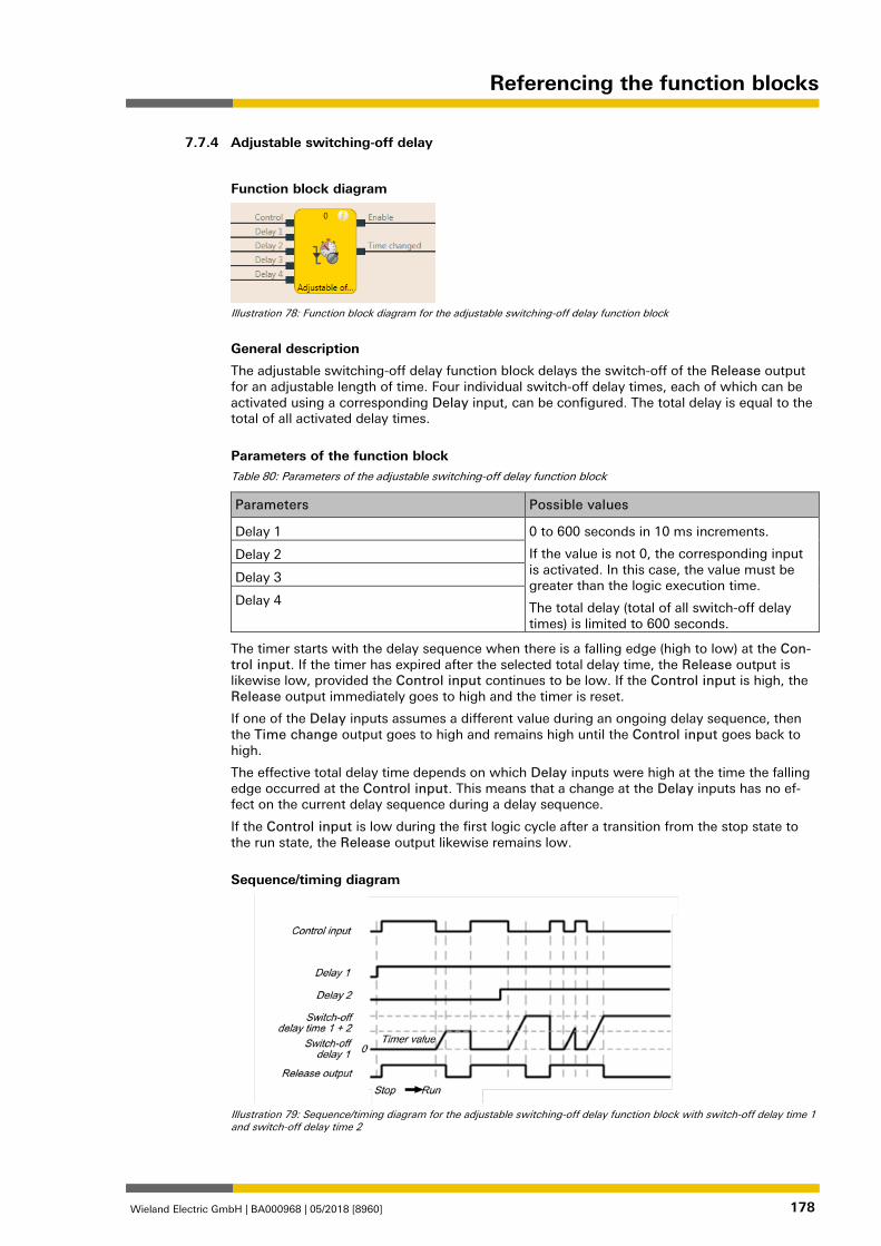
Referencing the function blocks
Wieland Electric GmbH | BA000968 | 05/2018 [8960] 178
Adjustable switching-off delay 839660555
Function block diagram
Illustration 78: Function block diagram for the adjustable switching-off delay function block
General description
The adjustable switching-off delay function block delays the switch-off of the Release output for an adjustable length of time. Four individual switch-off delay times, each of which can be activated using a corresponding Delay input, can be configured. The total delay is equal to the total of all activated delay times.
Parameters of the function block Table 80: Parameters of the adjustable switching-off delay function block
Parameters Possible values
Delay 1 0 to 600 seconds in 10 ms increments.
If the value is not 0, the corresponding input is activated. In this case, the value must be greater than the logic execution time.
The total delay (total of all switch-off delay times) is limited to 600 seconds.
Delay 2
Delay 3
Delay 4
The timer starts with the delay sequence when there is a falling edge (high to low) at the Con-trol input. If the timer has expired after the selected total delay time, the Release output is likewise low, provided the Control input continues to be low. If the Control input is high, the Release output immediately goes to high and the timer is reset.
If one of the Delay inputs assumes a different value during an ongoing delay sequence, then the Time change output goes to high and remains high until the Control input goes back to high.
The effective total delay time depends on which Delay inputs were high at the time the falling edge occurred at the Control input. This means that a change at the Delay inputs has no ef-fect on the current delay sequence during a delay sequence.
If the Control input is low during the first logic cycle after a transition from the stop state to the run state, the Release output likewise remains low.
Sequence/timing diagram
Illustration 79: Sequence/timing diagram for the adjustable switching-off delay function block with switch-off delay time 1 and switch-off delay time 2
7.7.4
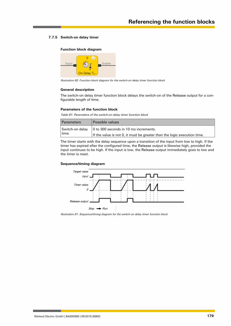
Referencing the function blocks
Wieland Electric GmbH | BA000968 | 05/2018 [8960] 179
Switch-on delay timer 839664907
Function block diagram
Illustration 80: Function block diagram for the switch-on delay timer function block
General description
The switch-on delay timer function block delays the switch-on of the Release output for a con-figurable length of time.
Parameters of the function block Table 81: Parameters of the switch-on delay timer function block
Parameters Possible values
Switch-on delay time
0 to 300 seconds in 10 ms increments.
If the value is not 0, it must be greater than the logic execution time.
The timer starts with the delay sequence upon a transition of the input from low to high. If the timer has expired after the configured time, the Release output is likewise high, provided the input continues to be high. If the input is low, the Release output immediately goes to low and the timer is reset.
Sequence/timing diagram
Illustration 81: Sequence/timing diagram for the switch-on delay timer function block
7.7.5
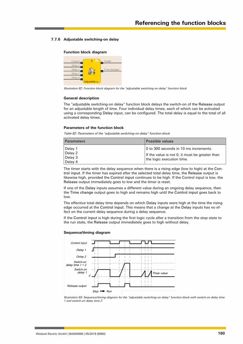
Referencing the function blocks
Wieland Electric GmbH | BA000968 | 05/2018 [8960] 180
Adjustable switching-on delay 839669259
Function block diagram
Illustration 82: Function block diagram for the "adjustable switching-on delay" function block
General description
The "adjustable switching-on delay" function block delays the switch-on of the Release output for an adjustable length of time. Four individual delay times, each of which can be activated using a corresponding Delay input, can be configured. The total delay is equal to the total of all activated delay times.
Parameters of the function block Table 82: Parameters of the "adjustable switching-on delay" function block
Parameters Possible values
Delay 1 Delay 2 Delay 3 Delay 4
0 to 300 seconds in 10 ms increments.
If the value is not 0, it must be greater than the logic execution time.
The timer starts with the delay sequence when there is a rising edge (low to high) at the Con-trol input. If the timer has expired after the selected total delay time, the Release output is likewise high, provided the Control input continues to be high. If the Control input is low, the Release output immediately goes to low and the timer is reset.
If one of the Delay inputs assumes a different value during an ongoing delay sequence, then the Time change output goes to high and remains high until the Control input goes back to low.
The effective total delay time depends on which Delay inputs were high at the time the rising edge occurred at the Control input. This means that a change at the Delay inputs has no ef-fect on the current delay sequence during a delay sequence.
If the Control input is high during the first logic cycle after a transition from the stop state to the run state, the Release output immediately goes to high without delay.
Sequence/timing diagram
Illustration 83: Sequence/timing diagram for the "adjustable switching-on delay" function block with switch-on delay time 1 and switch-on delay time 2
7.7.6
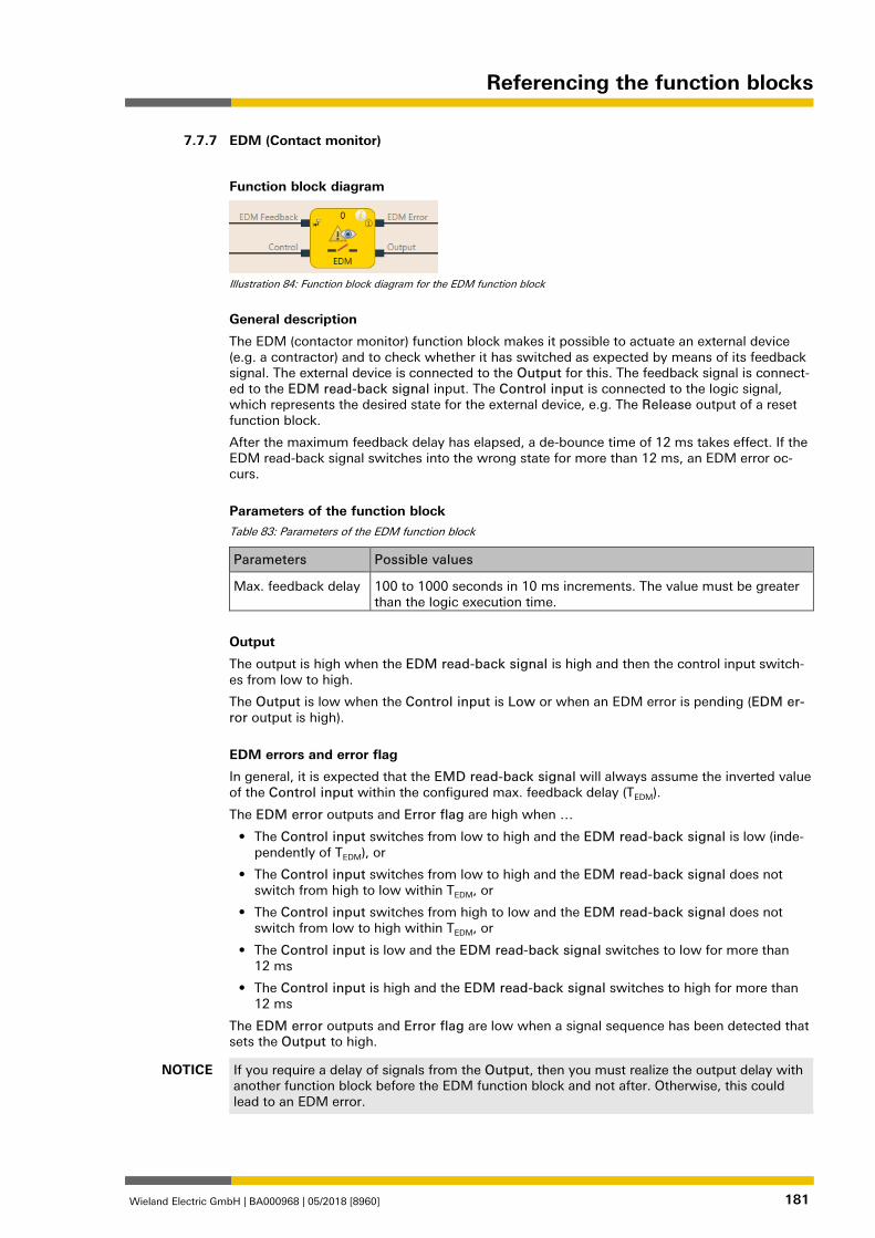
Referencing the function blocks
Wieland Electric GmbH | BA000968 | 05/2018 [8960] 181
EDM (Contact monitor) 839673611
Function block diagram
Illustration 84: Function block diagram for the EDM function block
General description
The EDM (contactor monitor) function block makes it possible to actuate an external device (e.g. a contractor) and to check whether it has switched as expected by means of its feedback signal. The external device is connected to the Output for this. The feedback signal is connect-ed to the EDM read-back signal input. The Control input is connected to the logic signal, which represents the desired state for the external device, e.g. The Release output of a reset function block.
After the maximum feedback delay has elapsed, a de-bounce time of 12 ms takes effect. If the EDM read-back signal switches into the wrong state for more than 12 ms, an EDM error oc-curs.
Parameters of the function block Table 83: Parameters of the EDM function block
Parameters Possible values
Max. feedback delay 100 to 1000 seconds in 10 ms increments. The value must be greater than the logic execution time.
Output
The output is high when the EDM read-back signal is high and then the control input switch-es from low to high.
The Output is low when the Control input is Low or when an EDM error is pending (EDM er-ror output is high).
EDM errors and error flag
In general, it is expected that the EMD read-back signal will always assume the inverted value of the Control input within the configured max. feedback delay (TEDM).
The EDM error outputs and Error flag are high when …
• The Control input switches from low to high and the EDM read-back signal is low (inde-pendently of TEDM), or
• The Control input switches from low to high and the EDM read-back signal does not switch from high to low within TEDM, or
• The Control input switches from high to low and the EDM read-back signal does not switch from low to high within TEDM, or
• The Control input is low and the EDM read-back signal switches to low for more than 12 ms
• The Control input is high and the EDM read-back signal switches to high for more than 12 ms
The EDM error outputs and Error flag are low when a signal sequence has been detected that sets the Output to high.
NOTICE If you require a delay of signals from the Output, then you must realize the output delay with another function block before the EDM function block and not after. Otherwise, this could lead to an EDM error.
7.7.7
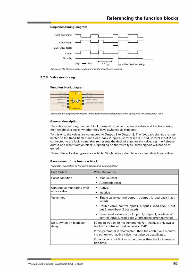
Referencing the function blocks
Wieland Electric GmbH | BA000968 | 05/2018 [8960] 182
Sequence/timing diagram
Illustration 85: Sequence/timing diagram for the EDM function block
Valve monitoring 839677963
Function block diagram
Illustration 86: Logical connections for the valve monitoring function block configured for a directional valve
General description
The valve monitoring function block makes it possible to actuate valves and to check, using their feedback signals, whether they have switched as expected.
To this end, the valves are connected to Output 1 to Output 2. The feedback signals are con-nected to the Read-back 1 and Read-back 2 inputs. Control input 1 and Control input 2 are connected to the logic signal that represents the desired state for the valve, e.g. the Release output of a reset function block. Depending on the valve type, some signals will not be re-quired.
Three different valve types are available: Single valves, double valves, and directional valves.
Parameters of the function block Table 84: Parameters of the valve monitoring function block
Parameters Possible values
Reset condition • Manual reset
• Automatic reset
Continuous monitoring with active valve
• Active
• Inactive
Valve type • Single valve (control output 1, output 1, read-back 1 acti-vated)
• Double valve (control input 1, output 1, read-back-1, out-put 2, read-back 2 activated)
• Directional valve (control input 1, output 1, read-back-1, control input 2, read-back 2, directional error activated)
Max. switch-on feedback delay
50 ms to 10 s in 10 ms increments (0 = inactive, only availa-ble from controller module version B-01).
If this parameter is deactivated, then the continuous monitor-ing option with active valve must also be deactivated.
If the value is not 0, it must be greater than the logic execu-tion time.
7.7.8
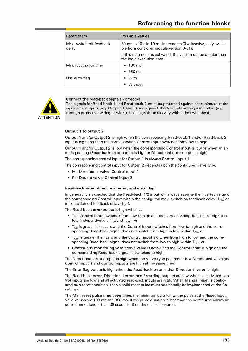
Referencing the function blocks
Wieland Electric GmbH | BA000968 | 05/2018 [8960] 183
Parameters Possible values
Max. switch-off feedback delay
50 ms to 10 s in 10 ms increments (0 = inactive, only availa-ble from controller module version B-01).
If this parameter is activated, the value must be greater than the logic execution time.
Min. reset pulse time • 100 ms
• 350 ms
Use error flag • With
• Without
ATTENTION
Connect the read-back signals correctly! The signals for Read-back 1 and Read-back 2 must be protected against short-circuits at the signals for outputs (e.g. Output 1 and 2) and against short-circuits among each other (e.g. through protective wiring or wiring these signals exclusively within the switchbox).
Output 1 to output 2
Output 1 and/or Output 2 is high when the corresponding Read-back 1 and/or Read-back 2 input is high and then the corresponding Control input switches from low to high.
Output 1 and/or Output 2 is low when the corresponding Control input is low or when an er-ror is pending (Read-back error output is high or Directional error output is high).
The corresponding control input for Output 1 is always Control input 1.
The corresponding control input for Output 2 depends upon the configured valve type.
• For Directional valve: Control input 1
• For Double valve: Control input 2
Read-back error, directional error, and error flag
In general, it is expected that the Read-back 1/2 input will always assume the inverted value of the corresponding Control input within the configured max. switch-on feedback delay (TON) or max. switch-off feedback delay (TOFF).
The Read-back error output is high when ...
• The Control input switches from low to high and the corresponding Read-back signal is low (independently of TONand TOFF), or
• TON is greater than zero and the Control input switches from low to high and the corre-sponding Read-back signal does not switch from high to low within TON, or
• TOFF is greater than zero and the Control input switches from high to low and the corre-sponding Read-back signal does not switch from low to high within TOFF, or
• Continuous monitoring with active valve is active and the Control input is high and the corresponding Read-back signal is switched to high.
The Directional error output is high when the Valve type parameter is = Directional valve and Control input 1 and Control input 2 are high at the same time.
The Error flag output is high when the Read-back error and/or Directional error is high.
The Read-back error, Directional error, and Error flag outputs are low when all activated con-trol inputs are low and all activated read-back inputs are high. When Manual reset is config-ured as a reset condition, then a valid reset pulse must additionally be implemented at the Re-set input.
The Min. reset pulse time determines the minimum duration of the pulse at the Reset input. Valid values are 100 ms and 350 ms. If the pulse duration is less than the configured minimum pulse time or longer than 30 seconds, then the pulse is ignored.
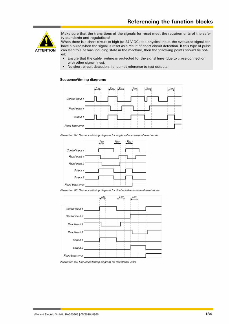
Referencing the function blocks
Wieland Electric GmbH | BA000968 | 05/2018 [8960] 184
ATTENTION
Make sure that the transitions of the signals for reset meet the requirements of the safe-ty standards and regulations! When there is a short-circuit to high (to 24 V DC) at a physical input, the evaluated signal can have a pulse when the signal is reset as a result of short-circuit detection. If this type of pulse can lead to a hazard-inducing state in the machine, then the following points should be not-ed: • Ensure that the cable routing is protected for the signal lines (due to cross-connection
with other signal lines). • No short-circuit detection, i.e. do not reference to test outputs.
Sequence/timing diagrams
Illustration 87: Sequence/timing diagram for single valve in manual reset mode
Illustration 88: Sequence/timing diagram for double valve in manual reset mode
Illustration 89: Sequence/timing diagram for directional valve
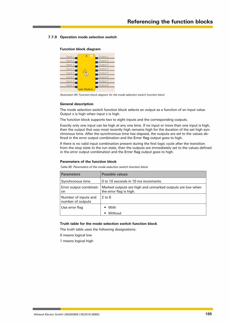
Referencing the function blocks
Wieland Electric GmbH | BA000968 | 05/2018 [8960] 185
Operation mode selection switch 839685643
Function block diagram
Illustration 90: Function block diagram for the mode selection switch function block
General description
The mode selection switch function block selects an output as a function of an input value. Output x is high when input x is high.
The function block supports two to eight inputs and the corresponding outputs.
Exactly only one input can be high at any one time. If no input or more than one input is high, then the output that was most recently high remains high for the duration of the set high syn-chronous time. After the synchronous time has elapsed, the outputs are set to the values de-fined in the error output combination and the Error flag output goes to high.
If there is no valid input combination present during the first logic cycle after the transition from the stop state to the run state, then the outputs are immediately set to the values defined in the error output combination and the Error flag output goes to high.
Parameters of the function block Table 85: Parameters of the mode selection switch function block
Parameters Possible values
Synchronous time 0 to 10 seconds in 10 ms increments
Error output combinati-on
Marked outputs are high and unmarked outputs are low when the error flag is high.
Number of inputs and number of outputs
2 to 8
Use error flag • With
• Without
Truth table for the mode selection switch function block
The truth table uses the following designations:
0 means logical low
1 means logical high
7.7.9
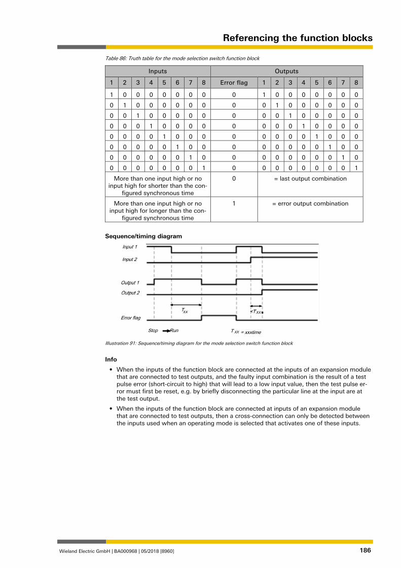
Referencing the function blocks
Wieland Electric GmbH | BA000968 | 05/2018 [8960] 186
Table 86: Truth table for the mode selection switch function block
Inputs Outputs
1 2 3 4 5 6 7 8 Error flag 1 2 3 4 5 6 7 8
1 0 0 0 0 0 0 0 0 1 0 0 0 0 0 0 0
0 1 0 0 0 0 0 0 0 0 1 0 0 0 0 0 0
0 0 1 0 0 0 0 0 0 0 0 1 0 0 0 0 0
0 0 0 1 0 0 0 0 0 0 0 0 1 0 0 0 0
0 0 0 0 1 0 0 0 0 0 0 0 0 1 0 0 0
0 0 0 0 0 1 0 0 0 0 0 0 0 0 1 0 0
0 0 0 0 0 0 1 0 0 0 0 0 0 0 0 1 0
0 0 0 0 0 0 0 1 0 0 0 0 0 0 0 0 1
More than one input high or no input high for shorter than the con-
figured synchronous time
0 = last output combination
More than one input high or no input high for longer than the con-
figured synchronous time
1 = error output combination
Sequence/timing diagram
Illustration 91: Sequence/timing diagram for the mode selection switch function block
Info
• When the inputs of the function block are connected at the inputs of an expansion module that are connected to test outputs, and the faulty input combination is the result of a test pulse error (short-circuit to high) that will lead to a low input value, then the test pulse er-ror must first be reset, e.g. by briefly disconnecting the particular line at the input are at the test output.
• When the inputs of the function block are connected at inputs of an expansion module that are connected to test outputs, then a cross-connection can only be detected between the inputs used when an operating mode is selected that activates one of these inputs.
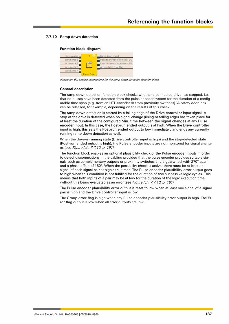
Referencing the function blocks
Wieland Electric GmbH | BA000968 | 05/2018 [8960] 187
Ramp down detection 839689995
Function block diagram
Illustration 92: Logical connections for the ramp down detection function block
General description
The ramp down detection function block checks whether a connected drive has stopped, i.e. that no pulses have been detected from the pulse encoder system for the duration of a config-urable time span (e.g. from an HTL encoder or from proximity switches). A safety door lock can be released, for example, depending on the results of this check.
The ramp down detection is started by a falling edge of the Drive controller input signal. A stop of the drive is detected when no signal change (rising or falling edge) has taken place for at least the duration of the configured Min. time between the signal changes at any Pulse encoder input. In this case, the Post-run ended output is at high. When the Drive controller input is high, this sets the Post-run ended output to low immediately and ends any currently running ramp down detection as well.
When the drive-is-running state (Drive controller input is high) and the stop-detected state (Post-run ended output is high), the Pulse encoder inputs are not monitored for signal chang-es (see Figure [ch. 7.7.10, p. 191]).
The function block enables an optional plausibility check of the Pulse encoder inputs in order to detect disconnections in the cabling provided that the pulse encoder provides suitable sig-nals such as complementary outputs or proximity switches and a gearwheel with 270° span and a phase offset of 180°. When the possibility check is active, there must be at least one signal of each signal pair at high at all times. The Pulse encoder plausibility error output goes to high when this condition is not fulfilled for the duration of two successive logic cycles. This means that both inputs of a pair may be at low for the duration of the logic execution time without this being evaluated as an error (see Figure [ch. 7.7.10, p. 191]).
The Pulse encoder plausibility error output is reset to low when at least one signal of a signal pair is high and the Drive controller input is low.
The Group error flag is high when any Pulse encoder plausibility error output is high. The Er-ror flag output is low when all error outputs are low.
7.7.10
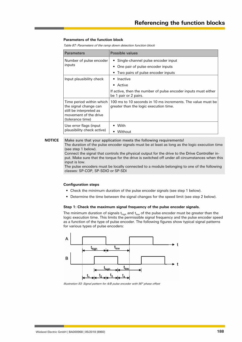
Referencing the function blocks
Wieland Electric GmbH | BA000968 | 05/2018 [8960] 188
Parameters of the function block Table 87: Parameters of the ramp down detection function block
Parameters Possible values
Number of pulse encoder inputs
• Single-channel pulse encoder input
• One pair of pulse encoder inputs
• Two pairs of pulse encoder inputs
Input plausibility check • Inactive
• Active
If active, then the number of pulse encoder inputs must either be 1 pair or 2 pairs.
Time period within which the signal change can still be interpreted as movement of the drive (tolerance time)
100 ms to 10 seconds in 10 ms increments. The value must be greater than the logic execution time.
Use error flags (input plausibility check active)
• With
• Without
NOTICE Make sure that your application meets the following requirements! The duration of the pulse encoder signals must be at least as long as the logic execution time (see step 1 below). Connect the signal that controls the physical output for the drive to the Drive Controller in-put. Make sure that the torque for the drive is switched off under all circumstances when this input is low. The pulse encoders must be locally connected to a module belonging to one of the following classes: SP-COP, SP-SDIO or SP-SDI
Configuration steps
• Check the minimum duration of the pulse encoder signals (see step 1 below).
• Determine the time between the signal changes for the speed limit (see step 2 below).
Step 1: Check the maximum signal frequency of the pulse encoder signals.
The minimum duration of signals thigh and tlow of the pulse encoder must be greater than the logic execution time. This limits the permissible signal frequency and the pulse encoder speed as a function of the type of pulse encoder. The following figures show typical signal patterns for various types of pulse encoders:
Illustration 93: Signal pattern for A/B pulse encoder with 90° phase offset
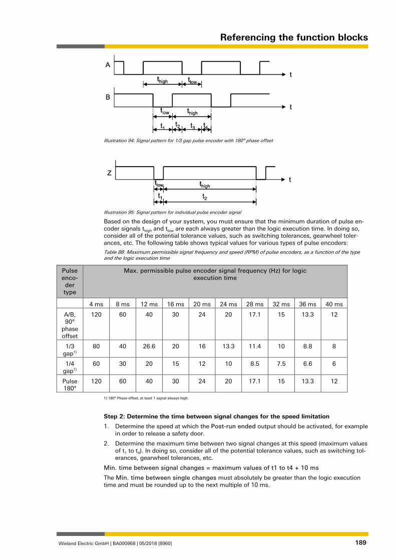
Referencing the function blocks
Wieland Electric GmbH | BA000968 | 05/2018 [8960] 189
Illustration 94: Signal pattern for 1/3 gap pulse encoder with 180° phase offset
Illustration 95: Signal pattern for individual pulse encoder signal
Based on the design of your system, you must ensure that the minimum duration of pulse en-coder signals thigh and tlow are each always greater than the logic execution time. In doing so, consider all of the potential tolerance values, such as switching tolerances, gearwheel toler-ances, etc. The following table shows typical values for various types of pulse encoders:
Table 88: Maximum permissible signal frequency and speed (RPM) of pulse encoders, as a function of the type and the logic execution time
Pulse enco-der type
Max. permissible pulse encoder signal frequency (Hz) for logic execution time
4 ms 8 ms 12 ms 16 ms 20 ms 24 ms 28 ms 32 ms 36 ms 40 ms
A/B, 90°
phase offset
120 60 40 30 24 20 17.1 15 13.3 12
1/3 gap1)
80 40 26.6 20 16 13.3 11.4 10 8.8 8
1/4 gap1)
60 30 20 15 12 10 8.5 7.5 6.6 6
Pulse 180°
120 60 40 30 24 20 17.1 15 13.3 12
1) 180° Phase offset, at least 1 signal always high.
Step 2: Determine the time between signal changes for the speed limitation
1. Determine the speed at which the Post-run ended output should be activated, for example in order to release a safety door.
2. Determine the maximum time between two signal changes at this speed (maximum values of t1 to t4). In doing so, consider all of the potential tolerance values, such as switching tol-erances, gearwheel tolerances, etc.
Min. time between signal changes = maximum values of t1 to t4 + 10 ms
The Min. time between single changes must absolutely be greater than the logic execution time and must be rounded up to the next multiple of 10 ms.
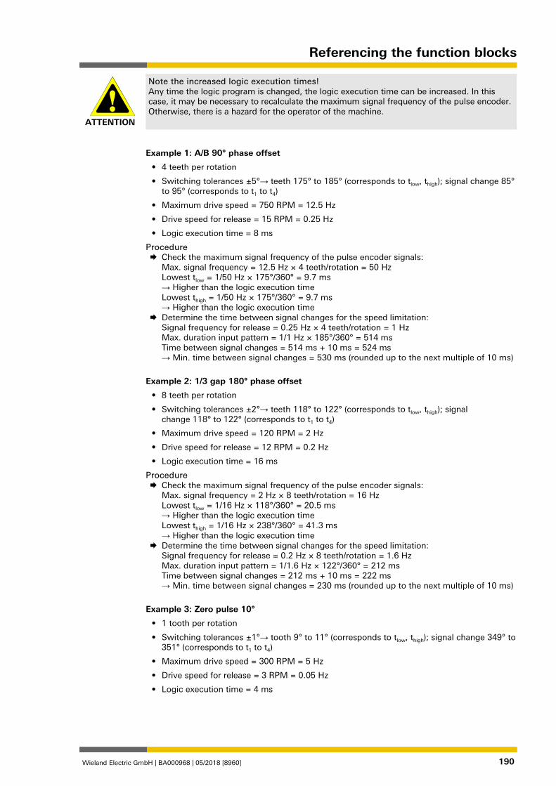
Referencing the function blocks
Wieland Electric GmbH | BA000968 | 05/2018 [8960] 190
ATTENTION
Note the increased logic execution times! Any time the logic program is changed, the logic execution time can be increased. In this case, it may be necessary to recalculate the maximum signal frequency of the pulse encoder. Otherwise, there is a hazard for the operator of the machine.
Example 1: A/B 90° phase offset
• 4 teeth per rotation
• Switching tolerances ±5°→ teeth 175° to 185° (corresponds to tlow, thigh); signal change 85° to 95° (corresponds to t1 to t4)
• Maximum drive speed = 750 RPM = 12.5 Hz
• Drive speed for release = 15 RPM = 0.25 Hz
• Logic execution time = 8 ms
Procedure Check the maximum signal frequency of the pulse encoder signals:
Max. signal frequency = 12.5 Hz × 4 teeth/rotation = 50 Hz Lowest tlow = 1/50 Hz × 175°/360° = 9.7 ms → Higher than the logic execution time Lowest thigh = 1/50 Hz × 175°/360° = 9.7 ms → Higher than the logic execution time
Determine the time between signal changes for the speed limitation: Signal frequency for release = 0.25 Hz × 4 teeth/rotation = 1 Hz Max. duration input pattern = 1/1 Hz × 185°/360° = 514 ms Time between signal changes = 514 ms + 10 ms = 524 ms → Min. time between signal changes = 530 ms (rounded up to the next multiple of 10 ms)
Example 2: 1/3 gap 180° phase offset
• 8 teeth per rotation
• Switching tolerances ±2°→ teeth 118° to 122° (corresponds to tlow, thigh); signal change 118° to 122° (corresponds to t1 to t4)
• Maximum drive speed = 120 RPM = 2 Hz
• Drive speed for release = 12 RPM = 0.2 Hz
• Logic execution time = 16 ms
Procedure Check the maximum signal frequency of the pulse encoder signals:
Max. signal frequency = 2 Hz × 8 teeth/rotation = 16 Hz Lowest tlow = 1/16 Hz × 118°/360° = 20.5 ms → Higher than the logic execution time Lowest thigh = 1/16 Hz × 238°/360° = 41.3 ms → Higher than the logic execution time
Determine the time between signal changes for the speed limitation: Signal frequency for release = 0.2 Hz × 8 teeth/rotation = 1.6 Hz Max. duration input pattern = 1/1.6 Hz × 122°/360° = 212 ms Time between signal changes = 212 ms + 10 ms = 222 ms → Min. time between signal changes = 230 ms (rounded up to the next multiple of 10 ms)
Example 3: Zero pulse 10°
• 1 tooth per rotation
• Switching tolerances ±1°→ tooth 9° to 11° (corresponds to tlow, thigh); signal change 349° to 351° (corresponds to t1 to t4)
• Maximum drive speed = 300 RPM = 5 Hz
• Drive speed for release = 3 RPM = 0.05 Hz
• Logic execution time = 4 ms
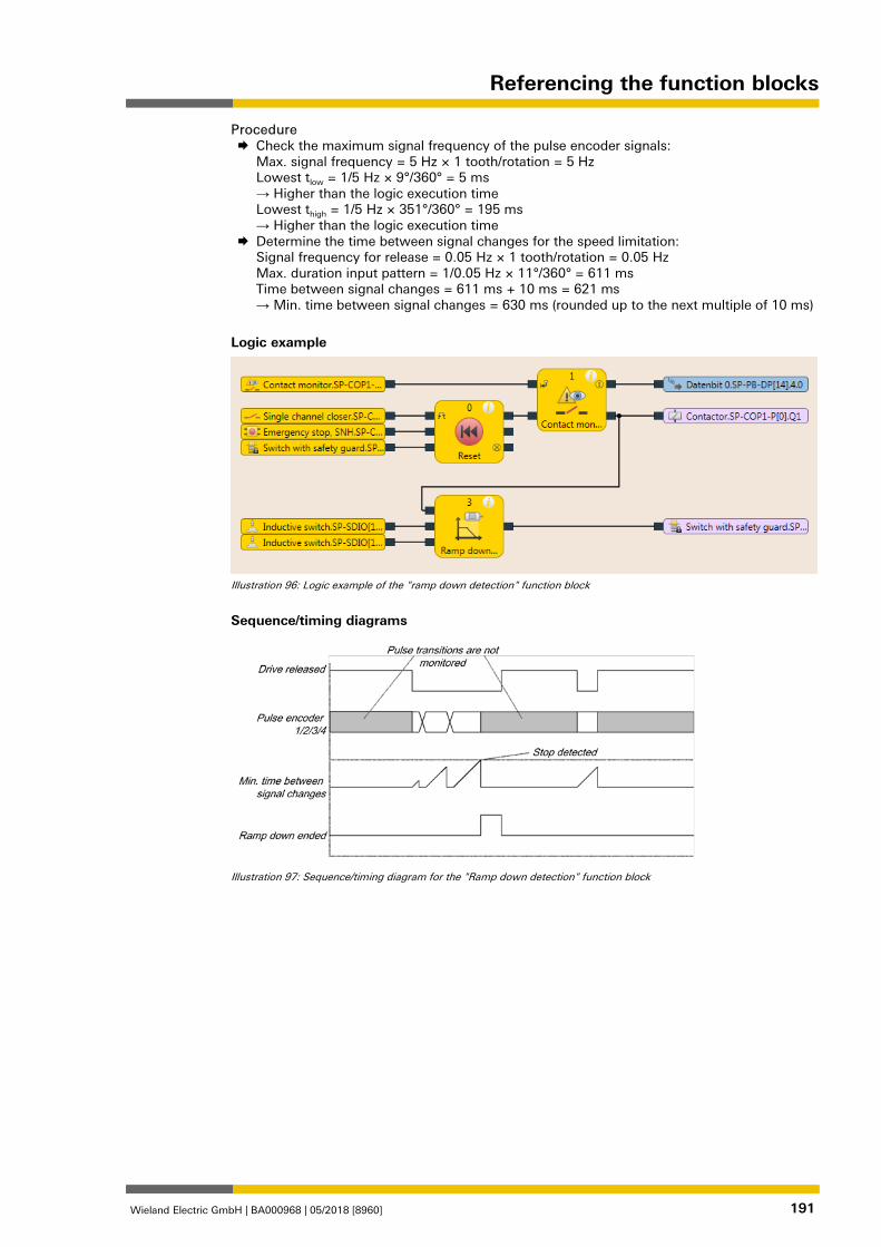
Referencing the function blocks
Wieland Electric GmbH | BA000968 | 05/2018 [8960] 191
Procedure Check the maximum signal frequency of the pulse encoder signals:
Max. signal frequency = 5 Hz × 1 tooth/rotation = 5 Hz Lowest tlow = 1/5 Hz × 9°/360° = 5 ms → Higher than the logic execution time Lowest thigh = 1/5 Hz × 351°/360° = 195 ms → Higher than the logic execution time
Determine the time between signal changes for the speed limitation: Signal frequency for release = 0.05 Hz × 1 tooth/rotation = 0.05 Hz Max. duration input pattern = 1/0.05 Hz × 11°/360° = 611 ms Time between signal changes = 611 ms + 10 ms = 621 ms → Min. time between signal changes = 630 ms (rounded up to the next multiple of 10 ms)
Logic example
Illustration 96: Logic example of the "ramp down detection" function block
Sequence/timing diagrams
Illustration 97: Sequence/timing diagram for the "Ramp down detection" function block
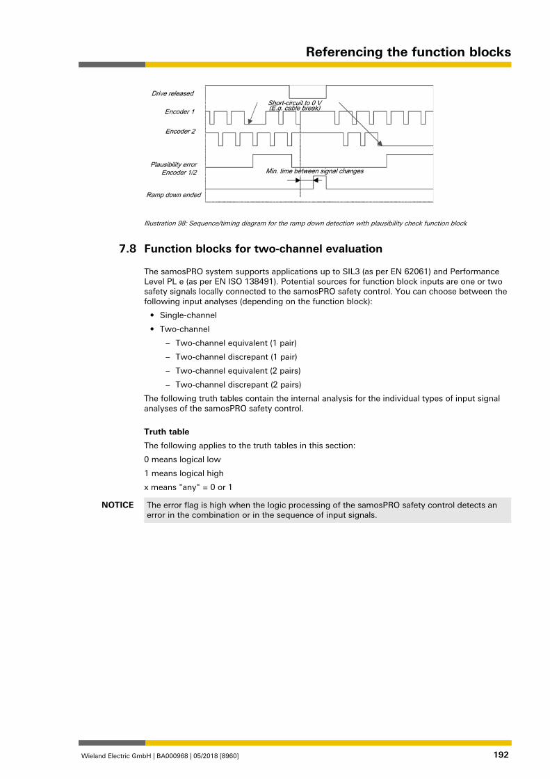
Referencing the function blocks
Wieland Electric GmbH | BA000968 | 05/2018 [8960] 192
Illustration 98: Sequence/timing diagram for the ramp down detection with plausibility check function block
Function blocks for two-channel evaluation 839720459
The samosPRO system supports applications up to SIL3 (as per EN 62061) and Performance Level PL e (as per EN ISO 138491). Potential sources for function block inputs are one or two safety signals locally connected to the samosPRO safety control. You can choose between the following input analyses (depending on the function block):
• Single-channel
• Two-channel
– Two-channel equivalent (1 pair)
– Two-channel discrepant (1 pair)
– Two-channel equivalent (2 pairs)
– Two-channel discrepant (2 pairs)
The following truth tables contain the internal analysis for the individual types of input signal analyses of the samosPRO safety control.
Truth table
The following applies to the truth tables in this section:
0 means logical low
1 means logical high
x means "any" = 0 or 1
NOTICE The error flag is high when the logic processing of the samosPRO safety control detects an error in the combination or in the sequence of input signals.
7.8
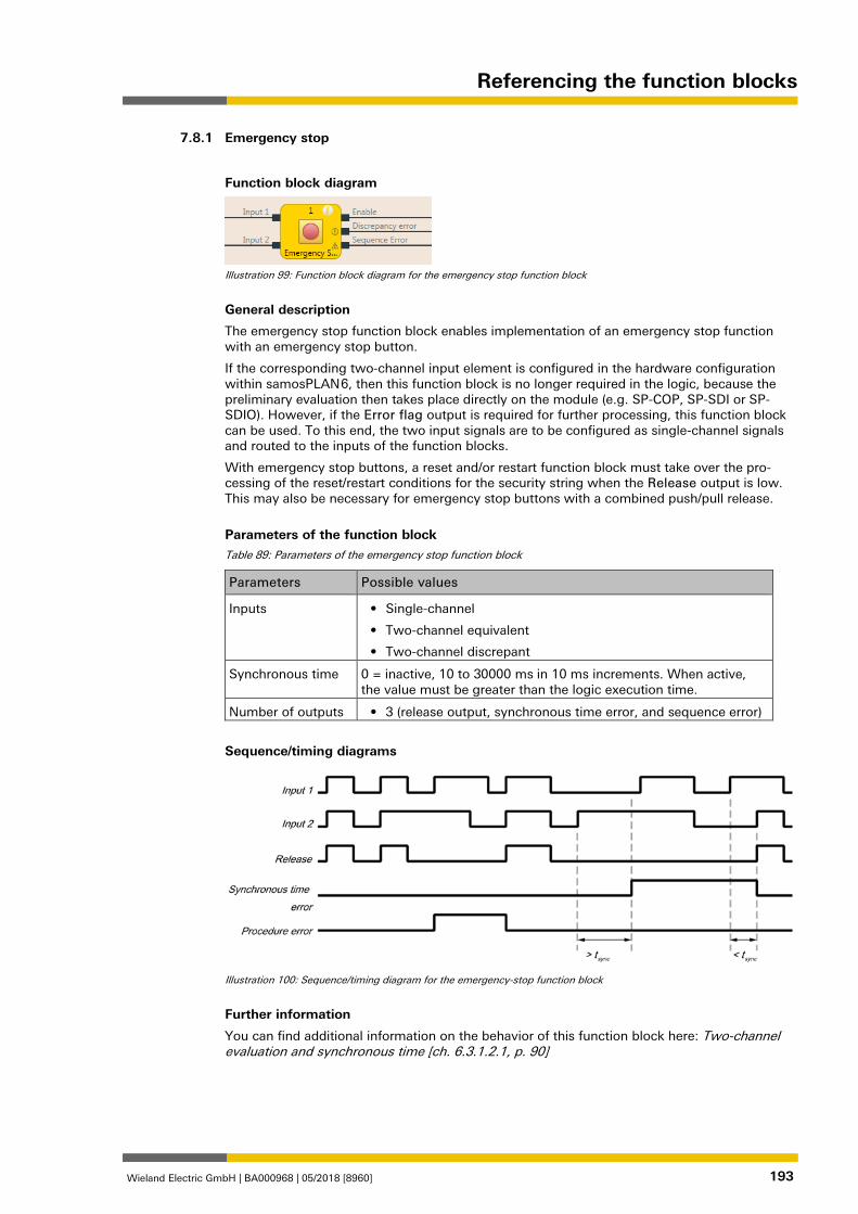
Referencing the function blocks
Wieland Electric GmbH | BA000968 | 05/2018 [8960] 193
Emergency stop 839721995
Function block diagram
Illustration 99: Function block diagram for the emergency stop function block
General description
The emergency stop function block enables implementation of an emergency stop function with an emergency stop button.
If the corresponding two-channel input element is configured in the hardware configuration within samosPLAN 6, then this function block is no longer required in the logic, because the preliminary evaluation then takes place directly on the module (e.g. SP-COP, SP-SDI or SP-SDIO). However, if the Error flag output is required for further processing, this function block can be used. To this end, the two input signals are to be configured as single-channel signals and routed to the inputs of the function blocks.
With emergency stop buttons, a reset and/or restart function block must take over the pro-cessing of the reset/restart conditions for the security string when the Release output is low. This may also be necessary for emergency stop buttons with a combined push/pull release.
Parameters of the function block Table 89: Parameters of the emergency stop function block
Parameters Possible values
Inputs • Single-channel
• Two-channel equivalent
• Two-channel discrepant
Synchronous time 0 = inactive, 10 to 30000 ms in 10 ms increments. When active, the value must be greater than the logic execution time.
Number of outputs • 3 (release output, synchronous time error, and sequence error)
Sequence/timing diagrams
Illustration 100: Sequence/timing diagram for the emergency-stop function block
Further information
You can find additional information on the behavior of this function block here: Two-channel evaluation and synchronous time [ch. 6.3.1.2.1, p. 90]
7.8.1
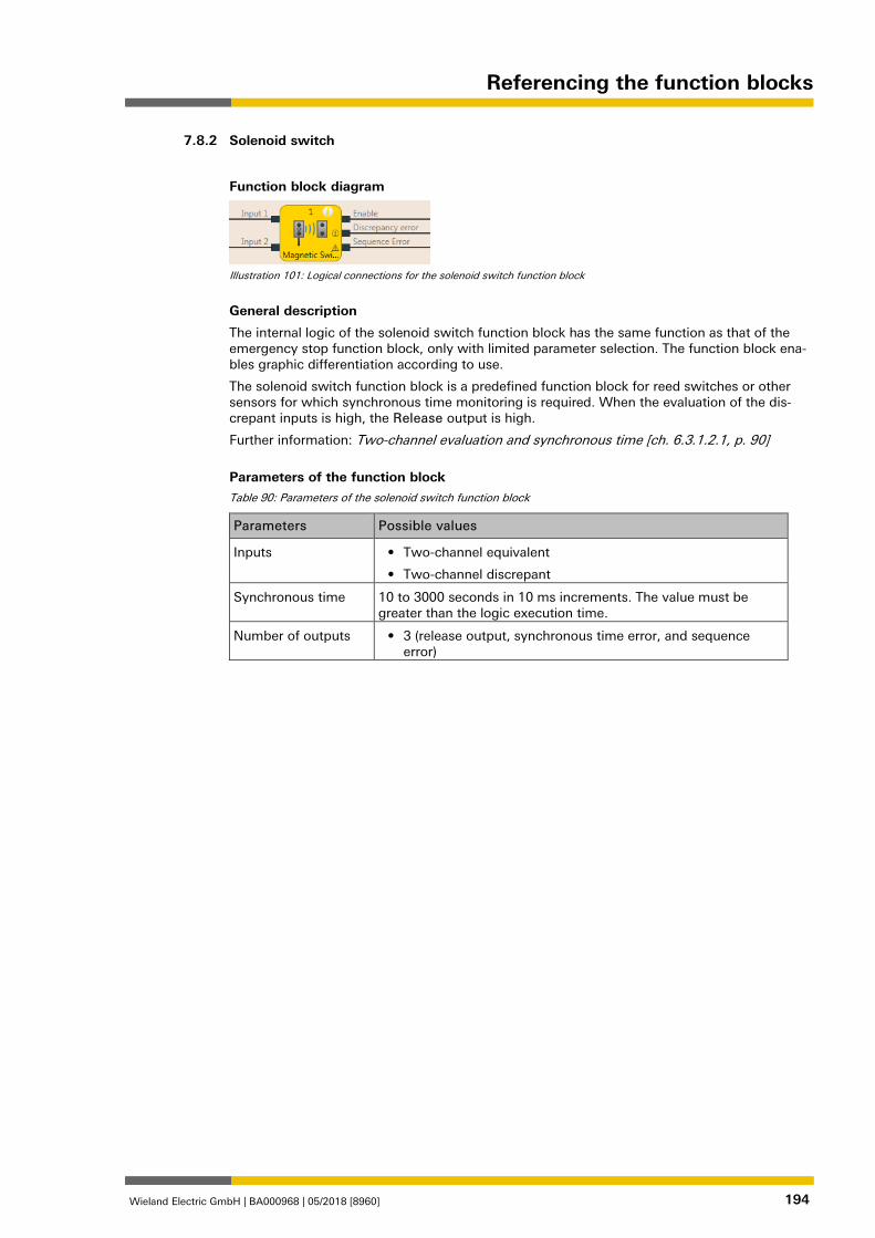
Referencing the function blocks
Wieland Electric GmbH | BA000968 | 05/2018 [8960] 194
Solenoid switch 839724683
Function block diagram
Illustration 101: Logical connections for the solenoid switch function block
General description
The internal logic of the solenoid switch function block has the same function as that of the emergency stop function block, only with limited parameter selection. The function block ena-bles graphic differentiation according to use.
The solenoid switch function block is a predefined function block for reed switches or other sensors for which synchronous time monitoring is required. When the evaluation of the dis-crepant inputs is high, the Release output is high.
Further information: Two-channel evaluation and synchronous time [ch. 6.3.1.2.1, p. 90]
Parameters of the function block Table 90: Parameters of the solenoid switch function block
Parameters Possible values
Inputs • Two-channel equivalent
• Two-channel discrepant
Synchronous time 10 to 3000 seconds in 10 ms increments. The value must be greater than the logic execution time.
Number of outputs • 3 (release output, synchronous time error, and sequence error)
7.8.2
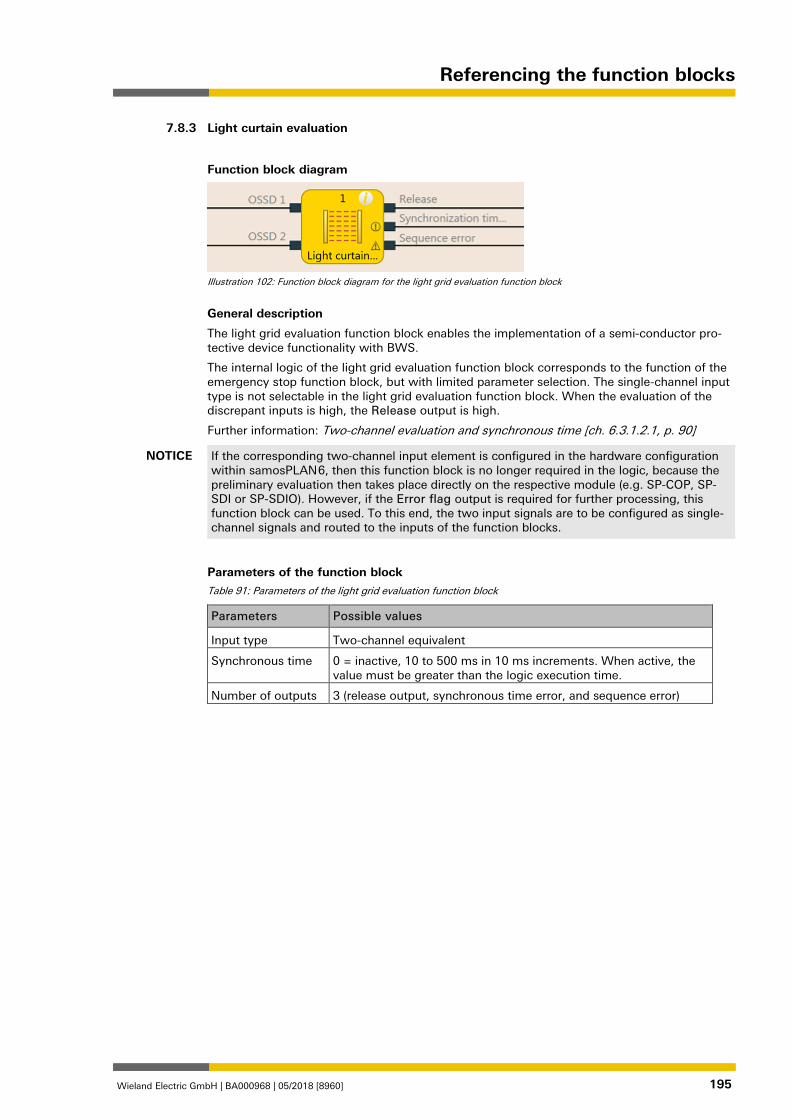
Referencing the function blocks
Wieland Electric GmbH | BA000968 | 05/2018 [8960] 195
Light curtain evaluation 839727371
Function block diagram
Illustration 102: Function block diagram for the light grid evaluation function block
General description
The light grid evaluation function block enables the implementation of a semi-conductor pro-tective device functionality with BWS.
The internal logic of the light grid evaluation function block corresponds to the function of the emergency stop function block, but with limited parameter selection. The single-channel input type is not selectable in the light grid evaluation function block. When the evaluation of the discrepant inputs is high, the Release output is high.
Further information: Two-channel evaluation and synchronous time [ch. 6.3.1.2.1, p. 90]
NOTICE If the corresponding two-channel input element is configured in the hardware configuration within samosPLAN 6, then this function block is no longer required in the logic, because the preliminary evaluation then takes place directly on the respective module (e.g. SP-COP, SP-SDI or SP-SDIO). However, if the Error flag output is required for further processing, this function block can be used. To this end, the two input signals are to be configured as single-channel signals and routed to the inputs of the function blocks.
Parameters of the function block Table 91: Parameters of the light grid evaluation function block
Parameters Possible values
Input type Two-channel equivalent
Synchronous time 0 = inactive, 10 to 500 ms in 10 ms increments. When active, the value must be greater than the logic execution time.
Number of outputs 3 (release output, synchronous time error, and sequence error)
7.8.3
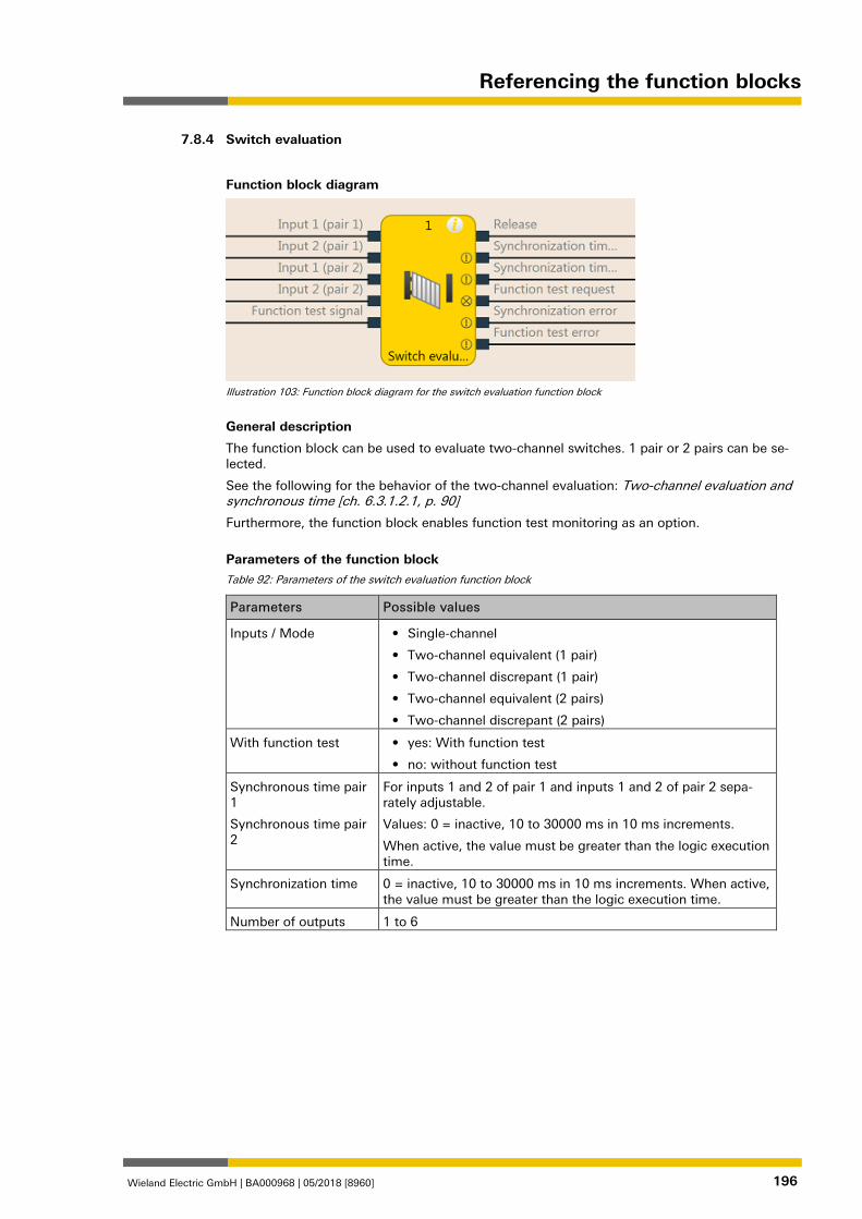
Referencing the function blocks
Wieland Electric GmbH | BA000968 | 05/2018 [8960] 196
Switch evaluation 839806859
Function block diagram
Illustration 103: Function block diagram for the switch evaluation function block
General description
The function block can be used to evaluate two-channel switches. 1 pair or 2 pairs can be se-lected.
See the following for the behavior of the two-channel evaluation: Two-channel evaluation and synchronous time [ch. 6.3.1.2.1, p. 90]
Furthermore, the function block enables function test monitoring as an option.
Parameters of the function block Table 92: Parameters of the switch evaluation function block
Parameters Possible values
Inputs / Mode • Single-channel
• Two-channel equivalent (1 pair)
• Two-channel discrepant (1 pair)
• Two-channel equivalent (2 pairs)
• Two-channel discrepant (2 pairs)
With function test • yes: With function test
• no: without function test
Synchronous time pair 1
Synchronous time pair 2
For inputs 1 and 2 of pair 1 and inputs 1 and 2 of pair 2 sepa-rately adjustable.
Values: 0 = inactive, 10 to 30000 ms in 10 ms increments.
When active, the value must be greater than the logic execution time.
Synchronization time 0 = inactive, 10 to 30000 ms in 10 ms increments. When active, the value must be greater than the logic execution time.
Number of outputs 1 to 6
7.8.4
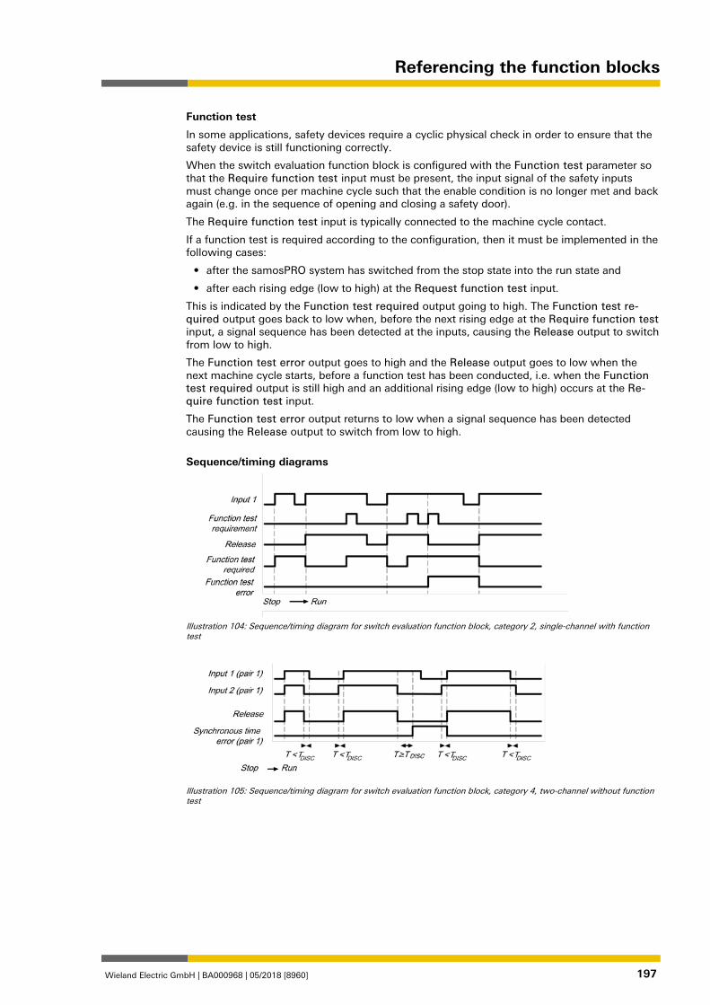
Referencing the function blocks
Wieland Electric GmbH | BA000968 | 05/2018 [8960] 197
Function test
In some applications, safety devices require a cyclic physical check in order to ensure that the safety device is still functioning correctly.
When the switch evaluation function block is configured with the Function test parameter so that the Require function test input must be present, the input signal of the safety inputs must change once per machine cycle such that the enable condition is no longer met and back again (e.g. in the sequence of opening and closing a safety door).
The Require function test input is typically connected to the machine cycle contact.
If a function test is required according to the configuration, then it must be implemented in the following cases:
• after the samosPRO system has switched from the stop state into the run state and
• after each rising edge (low to high) at the Request function test input.
This is indicated by the Function test required output going to high. The Function test re-quired output goes back to low when, before the next rising edge at the Require function test input, a signal sequence has been detected at the inputs, causing the Release output to switch from low to high.
The Function test error output goes to high and the Release output goes to low when the next machine cycle starts, before a function test has been conducted, i.e. when the Function test required output is still high and an additional rising edge (low to high) occurs at the Re-quire function test input.
The Function test error output returns to low when a signal sequence has been detected causing the Release output to switch from low to high.
Sequence/timing diagrams
Illustration 104: Sequence/timing diagram for switch evaluation function block, category 2, single-channel with function test
Illustration 105: Sequence/timing diagram for switch evaluation function block, category 4, two-channel without function test
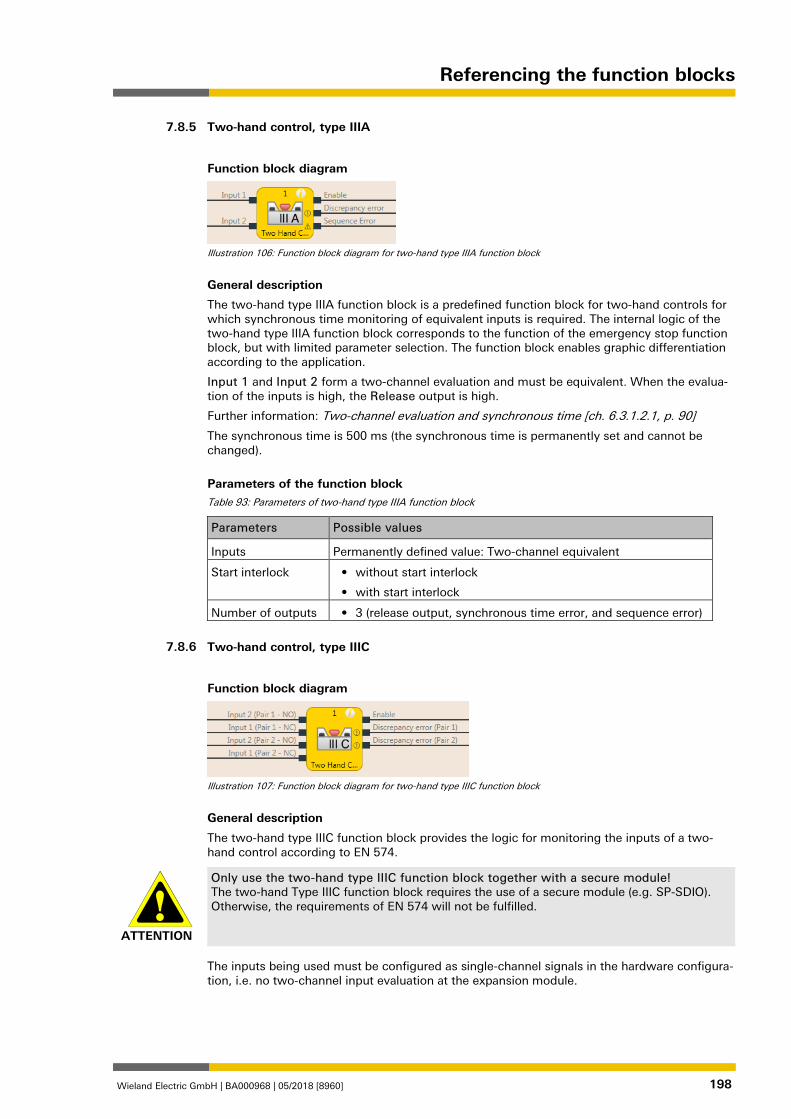
Referencing the function blocks
Wieland Electric GmbH | BA000968 | 05/2018 [8960] 198
Two-hand control, type IIIA 839809547
Function block diagram
Illustration 106: Function block diagram for two-hand type IIIA function block
General description
The two-hand type IIIA function block is a predefined function block for two-hand controls for which synchronous time monitoring of equivalent inputs is required. The internal logic of the two-hand type IIIA function block corresponds to the function of the emergency stop function block, but with limited parameter selection. The function block enables graphic differentiation according to the application.
Input 1 and Input 2 form a two-channel evaluation and must be equivalent. When the evalua-tion of the inputs is high, the Release output is high.
Further information: Two-channel evaluation and synchronous time [ch. 6.3.1.2.1, p. 90]
The synchronous time is 500 ms (the synchronous time is permanently set and cannot be changed).
Parameters of the function block Table 93: Parameters of two-hand type IIIA function block
Parameters Possible values
Inputs Permanently defined value: Two-channel equivalent
Start interlock • without start interlock
• with start interlock
Number of outputs • 3 (release output, synchronous time error, and sequence error)
Two-hand control, type IIIC 839812235
Function block diagram
Illustration 107: Function block diagram for two-hand type IIIC function block
General description
The two-hand type IIIC function block provides the logic for monitoring the inputs of a two-hand control according to EN 574.
ATTENTION
Only use the two-hand type IIIC function block together with a secure module! The two-hand Type IIIC function block requires the use of a secure module (e.g. SP-SDIO). Otherwise, the requirements of EN 574 will not be fulfilled.
The inputs being used must be configured as single-channel signals in the hardware configura-tion, i.e. no two-channel input evaluation at the expansion module.
7.8.5
7.8.6
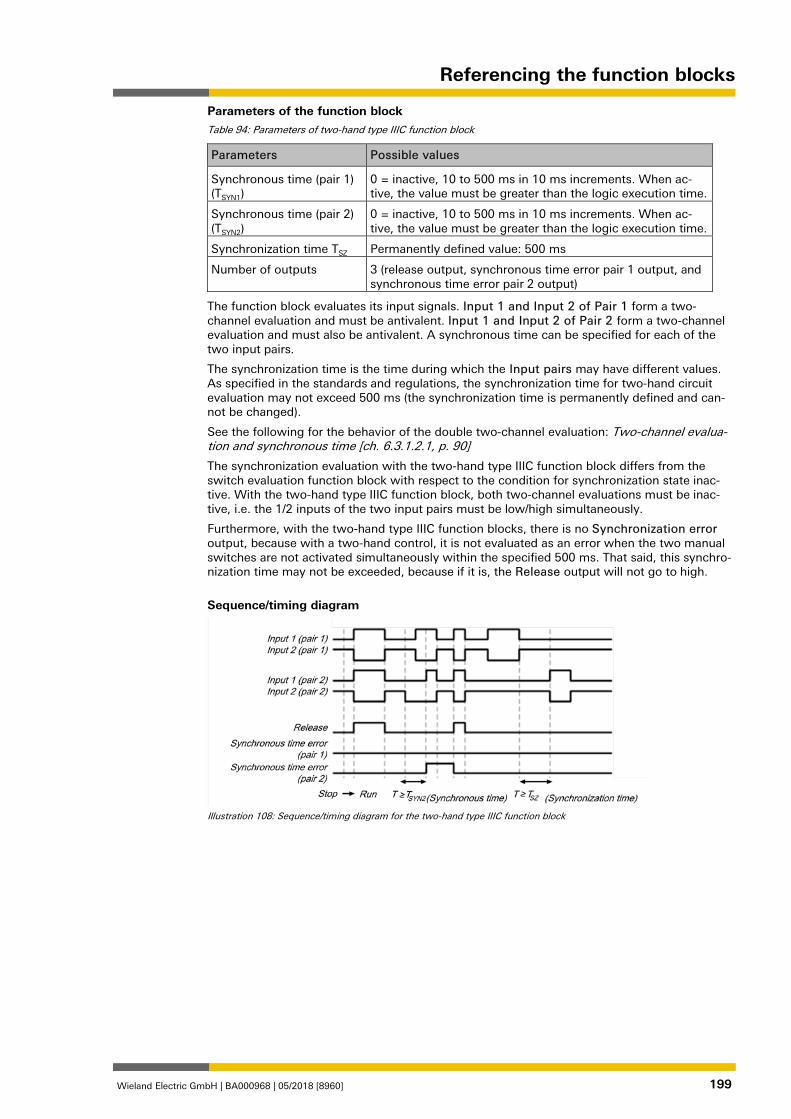
Referencing the function blocks
Wieland Electric GmbH | BA000968 | 05/2018 [8960] 199
Parameters of the function block Table 94: Parameters of two-hand type IIIC function block
Parameters Possible values
Synchronous time (pair 1) (TSYN1)
0 = inactive, 10 to 500 ms in 10 ms increments. When ac-tive, the value must be greater than the logic execution time.
Synchronous time (pair 2) (TSYN2)
0 = inactive, 10 to 500 ms in 10 ms increments. When ac-tive, the value must be greater than the logic execution time.
Synchronization time TSZ Permanently defined value: 500 ms
Number of outputs 3 (release output, synchronous time error pair 1 output, and synchronous time error pair 2 output)
The function block evaluates its input signals. Input 1 and Input 2 of Pair 1 form a two-channel evaluation and must be antivalent. Input 1 and Input 2 of Pair 2 form a two-channel evaluation and must also be antivalent. A synchronous time can be specified for each of the two input pairs.
The synchronization time is the time during which the Input pairs may have different values. As specified in the standards and regulations, the synchronization time for two-hand circuit evaluation may not exceed 500 ms (the synchronization time is permanently defined and can-not be changed).
See the following for the behavior of the double two-channel evaluation: Two-channel evalua-tion and synchronous time [ch. 6.3.1.2.1, p. 90]
The synchronization evaluation with the two-hand type IIIC function block differs from the switch evaluation function block with respect to the condition for synchronization state inac-tive. With the two-hand type IIIC function block, both two-channel evaluations must be inac-tive, i.e. the 1/2 inputs of the two input pairs must be low/high simultaneously.
Furthermore, with the two-hand type IIIC function blocks, there is no Synchronization error output, because with a two-hand control, it is not evaluated as an error when the two manual switches are not activated simultaneously within the specified 500 ms. That said, this synchro-nization time may not be exceeded, because if it is, the Release output will not go to high.
Sequence/timing diagram
Illustration 108: Sequence/timing diagram for the two-hand type IIIC function block
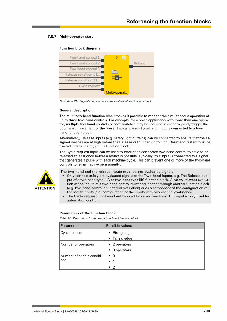
Referencing the function blocks
Wieland Electric GmbH | BA000968 | 05/2018 [8960] 200
Multi-operator start 839814923
Function block diagram
Illustration 109: Logical connections for the multi-two-hand function block
General description
The multi-two-hand function block makes it possible to monitor the simultaneous operation of up to three two-hand controls. For example, for a press application with more than one opera-tor, multiple two-hand controls or foot switches may be required in order to jointly trigger the downward movement of the press. Typically, each Two-hand input is connected to a two-hand function block.
Alternatively, Release inputs (e.g. safety light curtains) can be connected to ensure that the as-signed devices are at high before the Release output can go to high. Reset and restart must be treated independently of this function block.
The Cycle request input can be used to force each connected two-hand control to have to be released at least once before a restart is possible. Typically, this input is connected to a signal that generates a pulse with each machine cycle. This can prevent one or more of the two-hand controls to remain active permanently.
ATTENTION
The two-hand and the release inputs must be pre-evaluated signals! • Only connect safely pre-evaluated signals to the Two-hand inputs, e.g. The Release out-
put of a two-hand type IIIA or two-hand type IIIC function block. A safety-relevant evalua-tion of the inputs of a two-hand control must occur either through another function block (e.g. two-hand control or light grid evaluation) or as a component of the configuration of the safety inputs (e.g. configuration of the inputs with two-channel evaluation).
• The Cycle request input must not be used for safety functions. This input is only used for automation control.
Parameters of the function block Table 95: Parameters for the multi-two-hand function block
Parameters Possible values
Cycle request • Rising edge
• Falling edge
Number of operators • 2 operators
• 3 operators
Number of enable conditi-ons
• 0
• 1
• 2
7.8.7
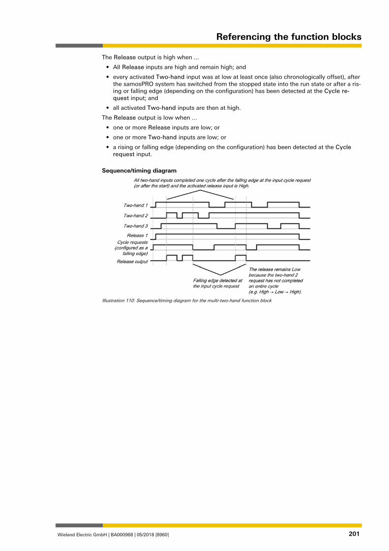
Referencing the function blocks
Wieland Electric GmbH | BA000968 | 05/2018 [8960] 201
The Release output is high when ...
• All Release inputs are high and remain high; and
• every activated Two-hand input was at low at least once (also chronologically offset), after the samosPRO system has switched from the stopped state into the run state or after a ris-ing or falling edge (depending on the configuration) has been detected at the Cycle re-quest input; and
• all activated Two-hand inputs are then at high.
The Release output is low when ...
• one or more Release inputs are low; or
• one or more Two-hand inputs are low; or
• a rising or falling edge (depending on the configuration) has been detected at the Cycle request input.
Sequence/timing diagram
Illustration 110: Sequence/timing diagram for the multi-two-hand function block
Referencing the function blocks
Wieland Electric GmbH | BA000968 | 05/2018 [8960] 202
Function blocks for parallel muting, sequential muting, and cross muting 1176646795
Overview and general description 839819147
Muting is the automatic temporary suppression of safety-oriented monitoring of an access area with the assistance of a contactless-acting safety device (BWS), while certain objects, e.g. pal-lets of material, are being moved into the hazardous area.
Muting sensors monitor the presence of the material while it is being transported. By carefully selecting the type and arrangement of the sensors, it is possible to differentiate between ob-jects and people.
Working together with the muting sensors and the contactless safety device, the object being conveyed generates a precisely defined signal sequence while it is moving in the hazardous ar-ea. The muting sensors must ensure that any potential hazard is excluded if a person enters the area being protected by the contactless safety device (i.e. a hazard-inducing state must be ended immediately). It must not be possible for a person to generate the same signal sequence as the object being conveyed.
The placement of muting sensors is determined by the shape of the object to be detected. To this end, the following options, among other things, are available with differing numbers of sensor input signals:
• Two sensors
• Two sensors and one C1 auxiliary signal
• Four sensors (two sensor pairs)
• Four sensors (two sensor pairs) and one C1 auxiliary signal
Muting sensor signals can be generated by the following external sensors:
• Optical sensors
• Inductive sensors
• Mechanical switches
• Signals from the control
If you use optical sensors for muting applications, use sensors with background suppression in order to ensure that only the material being conveyed meets the muting conditions. The sen-sors detect material only up to a certain distance. Objects that are further away therefore can-not fulfill the input conditions of the muting sensors.
There are three different function blocks available for muting:
• parallel muting Muting with two parallel sensor pairs
• sequential muting Muting with two sequential sensor pairs
• cross-muting (time-controlled, with/without direction detection) Muting with a crossed sensor pair
Info
• The muting cycle is the defined sequence of all processes that occur during muting.
• The muting cycle starts when the first muting sensor is activated. The muting cycle ends depending on the configuration in the function block for the muting end condition. It is not possible to reactivate muting until the previous muting cycle has ended.
• Material can be transported multiple times within a muting cycle if the muting condition is continuously maintained during this time, i.e. at least one sensor pair remains activated continuously.
7.9
7.9.1
Referencing the function blocks
Wieland Electric GmbH | BA000968 | 05/2018 [8960] 203
Safety information
Because the safety functions of a safety device are bypassed by the muting, multiple require-ments must be fulfilled, as shown below, in order to ensure the safety of the application.
ATTENTION
The general safety regulations and safety measures must be followed! If you use muting, make absolutely sure that the following information is followed for correct use of muting.
• Access to the hazardous area must be reliably detected by the contactless safety device or be prevented by other measures. It must not be possible for a person to bypass, climb over, crawl under, or cross the contactless safety device undetected. Note the operating instructions for the contactless safety device for correct installation and use of the device.
• Always follow the valid local, regional, and national regulations and standards that apply to your application. Make sure that your application corresponds to an appropriate risk analy-sis and avoidance strategy.
• Muting must never be used to convey a person into the hazardous area.
• Install the command devices for reset and override outside of the hazardous area, so that they can never be operated by someone who is inside of the hazardous area. In addition, the operator must have a full view of the hazardous area when operating a command de-vice.
• The muting sensors must be arranged such that, after interference in the protective field, the hazardous area can only be reached once the hazard-inducing state has been ended. A condition for this is that the safety distances required and defined in EN ISO 13855 are maintained. At least two muting signals, which are independent from one another, are re-quired.
• Muting may only be activated for the time span in which the object that is triggering the muting condition is blocking access to the hazardous area.
• The area between the contactless safety device and the muting sensors must be secured against someone accessing the area from the rear:
– With realization as parallel muting between the contactless safety device and A1/A2 sensors and between the contactless safety device and B1/B2 sensors (see Figure [ch. 7.9.6, p. 214]).
– With realization as sequential muting between the contactless safety device and A2 sensor and between the contactless safety device and B1 sensor (see Figure [ch. 7.9.7, p. 216]).
– With realization as cross-muting (time-controlled, with/without direction detection) be-tween the contactless safety device and A1 sensor and between the contactless safety device and A2 sensor (see Figure [ch. 7.9.8, p. 218]).
• Muting must take place automatically, but not depend on a single electric signal.
• The material to be transported must be detected over the entire length, i.e. there must not be any interruption in the output signals.
• Muting must be triggered by at least two independently wired signals (e.g. by muting sen-sors) and must not depend completely on software signals (e.g. on PLC).
• The muting condition must be ended immediately after the object has traveled through so that the safety device returns to its normal state, not suppressed by muting (i.e. so that it is again effective).
• The muting sensors must be arranged such that muting cannot be unintentionally trig-gered by a person.
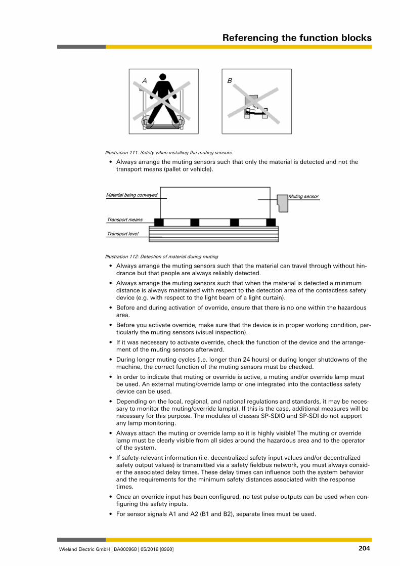
Referencing the function blocks
Wieland Electric GmbH | BA000968 | 05/2018 [8960] 204
Illustration 111: Safety when installing the muting sensors
• Always arrange the muting sensors such that only the material is detected and not the transport means (pallet or vehicle).
Illustration 112: Detection of material during muting
• Always arrange the muting sensors such that the material can travel through without hin-drance but that people are always reliably detected.
• Always arrange the muting sensors such that when the material is detected a minimum distance is always maintained with respect to the detection area of the contactless safety device (e.g. with respect to the light beam of a light curtain).
• Before and during activation of override, ensure that there is no one within the hazardous area.
• Before you activate override, make sure that the device is in proper working condition, par-ticularly the muting sensors (visual inspection).
• If it was necessary to activate override, check the function of the device and the arrange-ment of the muting sensors afterward.
• During longer muting cycles (i.e. longer than 24 hours) or during longer shutdowns of the machine, the correct function of the muting sensors must be checked.
• In order to indicate that muting or override is active, a muting and/or override lamp must be used. An external muting/override lamp or one integrated into the contactless safety device can be used.
• Depending on the local, regional, and national regulations and standards, it may be neces-sary to monitor the muting/override lamp(s). If this is the case, additional measures will be necessary for this purpose. The modules of classes SP-SDIO and SP-SDI do not support any lamp monitoring.
• Always attach the muting or override lamp so it is highly visible! The muting or override lamp must be clearly visible from all sides around the hazardous area and to the operator of the system.
• If safety-relevant information (i.e. decentralized safety input values and/or decentralized safety output values) is transmitted via a safety fieldbus network, you must always consid-er the associated delay times. These delay times can influence both the system behavior and the requirements for the minimum safety distances associated with the response times.
• Once an override input has been configured, no test pulse outputs can be used when con-figuring the safety inputs.
• For sensor signals A1 and A2 (B1 and B2), separate lines must be used.
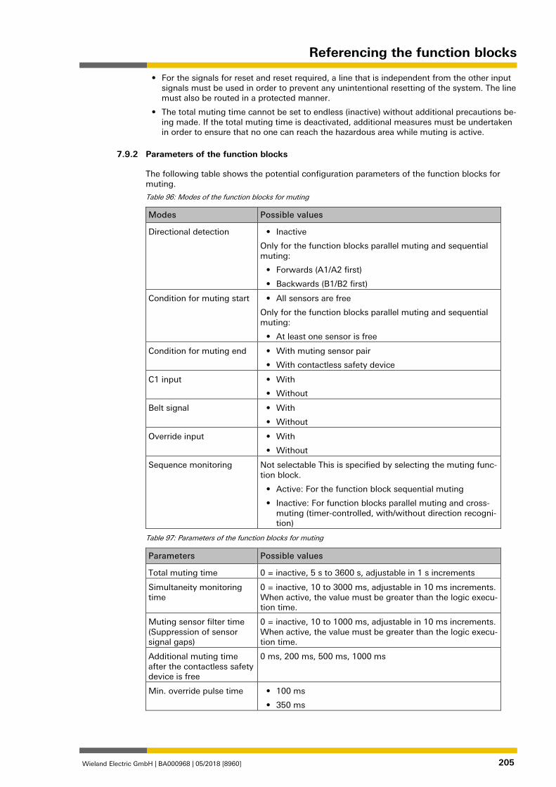
Referencing the function blocks
Wieland Electric GmbH | BA000968 | 05/2018 [8960] 205
• For the signals for reset and reset required, a line that is independent from the other input signals must be used in order to prevent any unintentional resetting of the system. The line must also be routed in a protected manner.
• The total muting time cannot be set to endless (inactive) without additional precautions be-ing made. If the total muting time is deactivated, additional measures must be undertaken in order to ensure that no one can reach the hazardous area while muting is active.
Parameters of the function blocks 839820171
The following table shows the potential configuration parameters of the function blocks for muting.
Table 96: Modes of the function blocks for muting
Modes Possible values
Directional detection • Inactive
Only for the function blocks parallel muting and sequential muting:
• Forwards (A1/A2 first)
• Backwards (B1/B2 first)
Condition for muting start • All sensors are free
Only for the function blocks parallel muting and sequential muting:
• At least one sensor is free
Condition for muting end • With muting sensor pair
• With contactless safety device
C1 input • With
• Without
Belt signal • With
• Without
Override input • With
• Without
Sequence monitoring Not selectable This is specified by selecting the muting func-tion block.
• Active: For the function block sequential muting
• Inactive: For function blocks parallel muting and cross-muting (timer-controlled, with/without direction recogni-tion)
Table 97: Parameters of the function blocks for muting
Parameters Possible values
Total muting time 0 = inactive, 5 s to 3600 s, adjustable in 1 s increments
Simultaneity monitoring time
0 = inactive, 10 to 3000 ms, adjustable in 10 ms increments. When active, the value must be greater than the logic execu-tion time.
Muting sensor filter time (Suppression of sensor signal gaps)
0 = inactive, 10 to 1000 ms, adjustable in 10 ms increments. When active, the value must be greater than the logic execu-tion time.
Additional muting time after the contactless safety device is free
0 ms, 200 ms, 500 ms, 1000 ms
Min. override pulse time • 100 ms
• 350 ms
7.9.2
Referencing the function blocks
Wieland Electric GmbH | BA000968 | 05/2018 [8960] 206
1125617291
Directional detection
Directional detection is used when material being conveyed has to be moved in a certain direc-tion. The direction depends on the sequence in which the muting sensors are activated.
When directional detection is inactive, the material being conveyed can be moved in both di-rections in order to fulfill the muting conditions. In this case, it does not matter which sensor pair is activated first.
If Forwards (A1/A2 first) was selected as the direction, the muting sensor pairs must be acti-vated in the sequence (A1/A2) before (B1/B2). In the opposite direction, muting is not possible. A transition from four active sensors to an inactive "B" sensor pair (0 or 1 sensor active) ends muting.
If Backwards (B1/B2 first) was selected as the direction, the muting sensor pairs must be ac-tivated in the sequence (B1/B2) before (A1/A2). Muting is not possible in the forward direction. A transition from four active sensors to an inactive "A" sensor pair (0 or 1 sensor active) ends muting. 1125619467
Condition for muting start
The Condition for muting start parameter determines when a valid muting sequence can begin. The Condition for muting start can be defined as follows:
• Both sensors are free: All muting sensors have jointly or individually gone to low and the OSSDs of the safety device (e.g. safety light curtain) are high (i.e. the protective field is free);
or
• At least one sensor is free: All muting sensors except for the last muting sensor are low and the OSSDs of the safety device (e.g. safety light curtain) are high (i.e. the protective field is free).
If a higher throughput rate is required, it can be advantageous to enable the start of the next muting sequence as soon as the material being conveyed has passed the protective device and all of the muting sensors with the exception of the last one (i.e. At least one sensor is free). 1125621387
Condition for muting end
Contrary to the Condition of the other sensor pair for muting start parameter, the Condition for muting end parameter determines when a valid muting state is over. You can select when the Condition for muting end occurs.
• With muting sensor pair: When a muting sensor of the last muting sensor pair goes to low (sensor free)
or
• With contactless safety device: When the OSSDs of the safety device (e.g. safety light curtain) indicate that the protective field is no longer being violated, i.e. that the protective field is free and the OSSDs are back at high.
If the OSSD input of the contactless safety device is low after muting end (e.g. due to a viola-tion of the safety device's protective field), before the next valid muting sequence has begun, the Release output of the function block goes to low. The next muting cycle cannot begin until the Condition for muting end has been fulfilled. 1126173707
Total muting time
The Total muting time is used in order to limit the maximum duration of the muting sequence. If the set value for the Total muting time is exceeded, then the Muting error outputs and the Error flag go to high and the Release output goes to low.
The timer for the Total muting time starts upon activation of the muting function, and this is indicated by the transition of the Muting status output to high. The timer for the Total muting time is maintained and reset to zero when the muting function is again deactivated. If an op-tional Belt signal input is used, the timer pauses for the total muting time when the Belt signal input is high and thus indicates that the conveyor belt has stopped. 1126175627
7.9.2.1
7.9.2.2
7.9.2.3
7.9.2.4
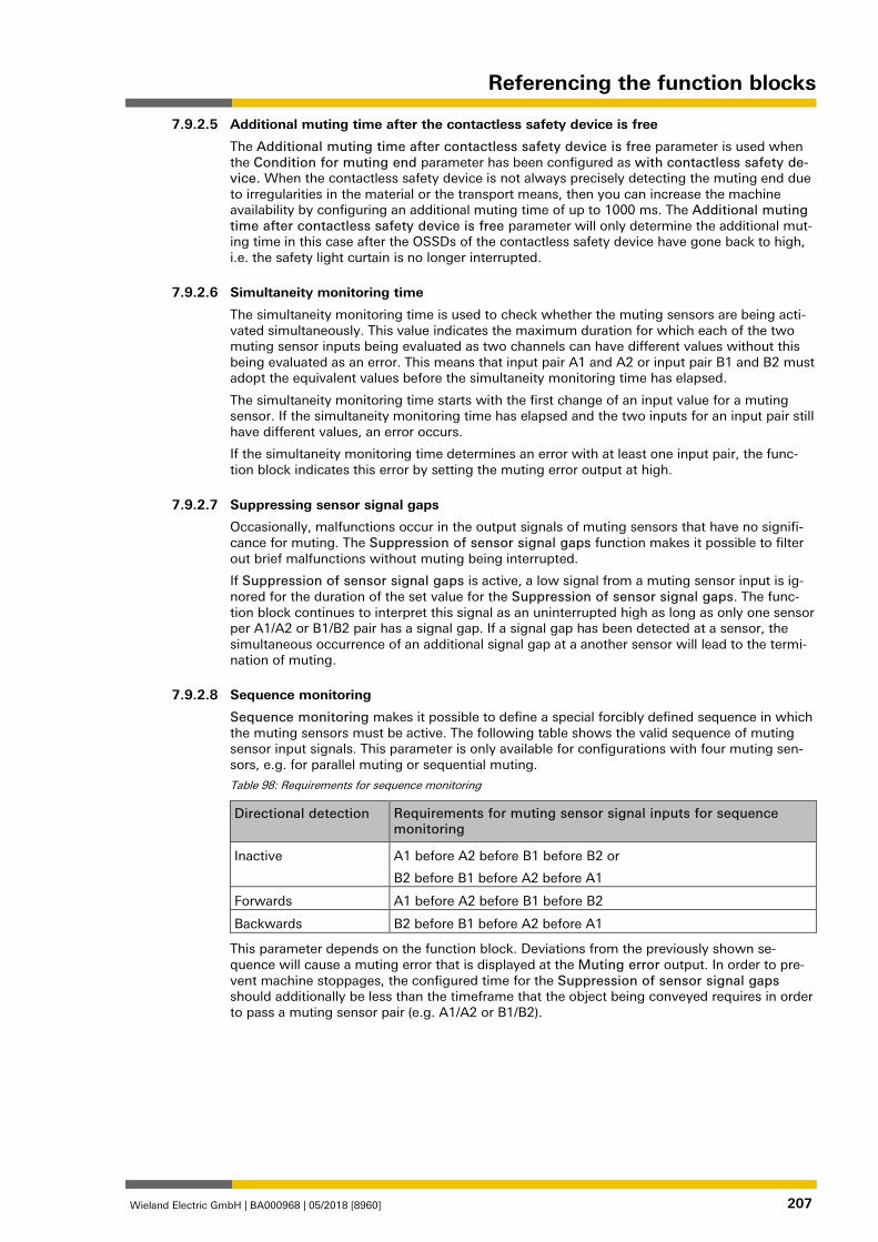
Referencing the function blocks
Wieland Electric GmbH | BA000968 | 05/2018 [8960] 207
Additional muting time after the contactless safety device is free
The Additional muting time after contactless safety device is free parameter is used when the Condition for muting end parameter has been configured as with contactless safety de-vice. When the contactless safety device is not always precisely detecting the muting end due to irregularities in the material or the transport means, then you can increase the machine availability by configuring an additional muting time of up to 1000 ms. The Additional muting time after contactless safety device is free parameter will only determine the additional mut-ing time in this case after the OSSDs of the contactless safety device have gone back to high, i.e. the safety light curtain is no longer interrupted. 1126177547
Simultaneity monitoring time
The simultaneity monitoring time is used to check whether the muting sensors are being acti-vated simultaneously. This value indicates the maximum duration for which each of the two muting sensor inputs being evaluated as two channels can have different values without this being evaluated as an error. This means that input pair A1 and A2 or input pair B1 and B2 must adopt the equivalent values before the simultaneity monitoring time has elapsed.
The simultaneity monitoring time starts with the first change of an input value for a muting sensor. If the simultaneity monitoring time has elapsed and the two inputs for an input pair still have different values, an error occurs.
If the simultaneity monitoring time determines an error with at least one input pair, the func-tion block indicates this error by setting the muting error output at high. 1126179467
Suppressing sensor signal gaps
Occasionally, malfunctions occur in the output signals of muting sensors that have no signifi-cance for muting. The Suppression of sensor signal gaps function makes it possible to filter out brief malfunctions without muting being interrupted.
If Suppression of sensor signal gaps is active, a low signal from a muting sensor input is ig-nored for the duration of the set value for the Suppression of sensor signal gaps. The func-tion block continues to interpret this signal as an uninterrupted high as long as only one sensor per A1/A2 or B1/B2 pair has a signal gap. If a signal gap has been detected at a sensor, the simultaneous occurrence of an additional signal gap at a another sensor will lead to the termi-nation of muting. 1126181387
Sequence monitoring
Sequence monitoring makes it possible to define a special forcibly defined sequence in which the muting sensors must be active. The following table shows the valid sequence of muting sensor input signals. This parameter is only available for configurations with four muting sen-sors, e.g. for parallel muting or sequential muting.
Table 98: Requirements for sequence monitoring
Directional detection Requirements for muting sensor signal inputs for sequence monitoring
Inactive A1 before A2 before B1 before B2 or
B2 before B1 before A2 before A1
Forwards A1 before A2 before B1 before B2
Backwards B2 before B1 before A2 before A1
This parameter depends on the function block. Deviations from the previously shown se-quence will cause a muting error that is displayed at the Muting error output. In order to pre-vent machine stoppages, the configured time for the Suppression of sensor signal gaps should additionally be less than the timeframe that the object being conveyed requires in order to pass a muting sensor pair (e.g. A1/A2 or B1/B2). 1126183307
7.9.2.5
7.9.2.6
7.9.2.7
7.9.2.8
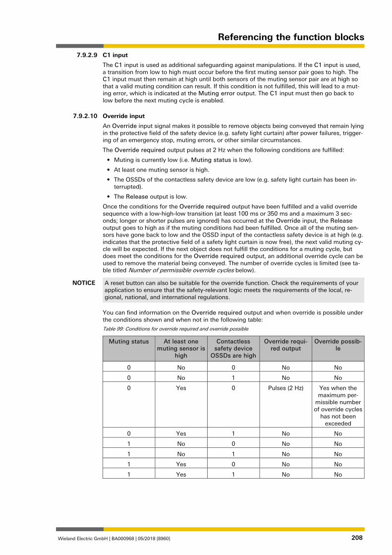
Referencing the function blocks
Wieland Electric GmbH | BA000968 | 05/2018 [8960] 208
C1 input
The C1 input is used as additional safeguarding against manipulations. If the C1 input is used, a transition from low to high must occur before the first muting sensor pair goes to high. The C1 input must then remain at high until both sensors of the muting sensor pair are at high so that a valid muting condition can result. If this condition is not fulfilled, this will lead to a mut-ing error, which is indicated at the Muting error output. The C1 input must then go back to low before the next muting cycle is enabled. 1126185227
Override input
An Override input signal makes it possible to remove objects being conveyed that remain lying in the protective field of the safety device (e.g. safety light curtain) after power failures, trigger-ing of an emergency stop, muting errors, or other similar circumstances.
The Override required output pulses at 2 Hz when the following conditions are fulfilled:
• Muting is currently low (i.e. Muting status is low).
• At least one muting sensor is high.
• The OSSDs of the contactless safety device are low (e.g. safety light curtain has been in-terrupted).
• The Release output is low.
Once the conditions for the Override required output have been fulfilled and a valid override sequence with a low-high-low transition (at least 100 ms or 350 ms and a maximum 3 sec-onds; longer or shorter pulses are ignored) has occurred at the Override input, the Release output goes to high as if the muting conditions had been fulfilled. Once all of the muting sen-sors have gone back to low and the OSSD input of the contactless safety device is at high (e.g. indicates that the protective field of a safety light curtain is now free), the next valid muting cy-cle will be expected. If the next object does not fulfill the conditions for a muting cycle, but does meet the conditions for the Override required output, an additional override cycle can be used to remove the material being conveyed. The number of override cycles is limited (see ta-ble titled Number of permissible override cycles below).
NOTICE A reset button can also be suitable for the override function. Check the requirements of your application to ensure that the safety-relevant logic meets the requirements of the local, re-gional, national, and international regulations.
You can find information on the Override required output and when override is possible under the conditions shown and when not in the following table:
Table 99: Conditions for override required and override possible
Muting status At least one muting sensor is
high
Contactless safety device
OSSDs are high
Override requi-red output
Override possib-le
0 No 0 No No
0 No 1 No No
0 Yes 0 Pulses (2 Hz) Yes when the maximum per-
missible number of override cycles
has not been exceeded
0 Yes 1 No No
1 No 0 No No
1 No 1 No No
1 Yes 0 No No
1 Yes 1 No No
7.9.2.9
7.9.2.10
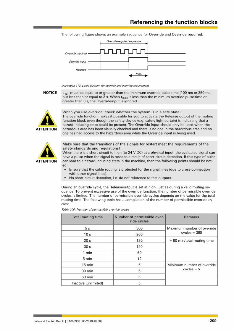
Referencing the function blocks
Wieland Electric GmbH | BA000968 | 05/2018 [8960] 209
The following figure shows an example sequence for Override and Override required.
Illustration 113: Logic diagram for override and override requirement
NOTICE tHIGH must be equal to or greater than the minimum override pulse time (100 ms or 350 ms) but less than or equal to 3 s. When tHIGH is less than the minimum override pulse time or greater than 3 s, the Overrideinput is ignored.
ATTENTION
When you use override, check whether the system is in a safe state! The override function makes it possible for you to activate the Release output of the muting function block even though the safety device (e.g. safety light curtain) is indicating that a hazard-inducing state could be present. The Override input should only be used when the hazardous area has been visually checked and there is no one in the hazardous area and no one has had access to the hazardous area while the Override input is being used.
ATTENTION
Make sure that the transitions of the signals for restart meet the requirements of the safety standards and regulations! When there is a short-circuit to high (to 24 V DC) at a physical input, the evaluated signal can have a pulse when the signal is reset as a result of short-circuit detection. If this type of pulse can lead to a hazard-inducing state in the machine, then the following points should be not-ed: • Ensure that the cable routing is protected for the signal lines (due to cross-connection
with other signal lines). • No short-circuit detection, i.e. do not reference to test outputs.
During an override cycle, the Releaseoutput is set at high, just as during a valid muting se-quence. To prevent excessive use of the override function, the number of permissible override cycles is limited. The number of permissible override cycles depends on the value for the total muting time. The following table has a compilation of the number of permissible override cy-cles:
Table 100: Number of permissible override cycles
Total muting time Number of permissible over-ride cycles
Remarks
5 s 360 Maximum number of override cycles = 360 10 s 360
20 s 180 = 60 min/total muting time
30 s 120
1 min 60
5 min 12
15 min 5 Minimum number of override cycles = 5 30 min 5
60 min 5
Inactive (unlimited) 5
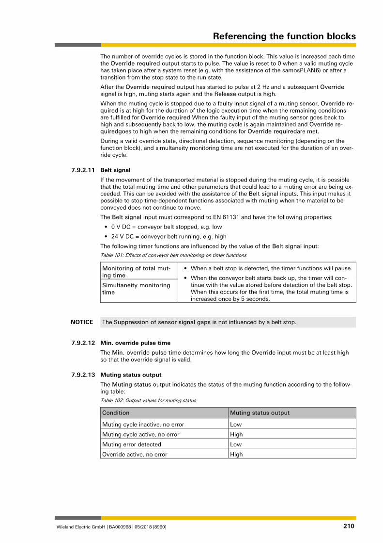
Referencing the function blocks
Wieland Electric GmbH | BA000968 | 05/2018 [8960] 210
The number of override cycles is stored in the function block. This value is increased each time the Override required output starts to pulse. The value is reset to 0 when a valid muting cycle has taken place after a system reset (e.g. with the assistance of the samosPLAN 6) or after a transition from the stop state to the run state.
After the Override required output has started to pulse at 2 Hz and a subsequent Override signal is high, muting starts again and the Release output is high.
When the muting cycle is stopped due to a faulty input signal of a muting sensor, Override re-quired is at high for the duration of the logic execution time when the remaining conditions are fulfilled for Override required When the faulty input of the muting sensor goes back to high and subsequently back to low, the muting cycle is again maintained and Override re-quiredgoes to high when the remaining conditions for Override requiredare met.
During a valid override state, directional detection, sequence monitoring (depending on the function block), and simultaneity monitoring time are not executed for the duration of an over-ride cycle. 1126187147
Belt signal
If the movement of the transported material is stopped during the muting cycle, it is possible that the total muting time and other parameters that could lead to a muting error are being ex-ceeded. This can be avoided with the assistance of the Belt signal inputs. This input makes it possible to stop time-dependent functions associated with muting when the material to be conveyed does not continue to move.
The Belt signal input must correspond to EN 61131 and have the following properties:
• 0 V DC = conveyor belt stopped, e.g. low
• 24 V DC = conveyor belt running, e.g. high
The following timer functions are influenced by the value of the Belt signal input:
Table 101: Effects of conveyor belt monitoring on timer functions
Monitoring of total mut-ing time
• When a belt stop is detected, the timer functions will pause.
• When the conveyor belt starts back up, the timer will con-tinue with the value stored before detection of the belt stop. When this occurs for the first time, the total muting time is increased once by 5 seconds.
Simultaneity monitoring time
NOTICE The Suppression of sensor signal gaps is not influenced by a belt stop.
1126189067
Min. override pulse time
The Min. override pulse time determines how long the Override input must be at least high so that the override signal is valid. 1126190987
Muting status output
The Muting status output indicates the status of the muting function according to the follow-ing table:
Table 102: Output values for muting status
Condition Muting status output
Muting cycle inactive, no error Low
Muting cycle active, no error High
Muting error detected Low
Override active, no error High
1126192907
7.9.2.11
7.9.2.12
7.9.2.13
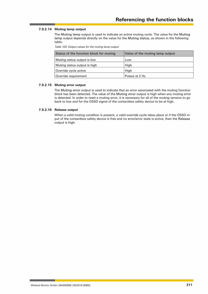
Referencing the function blocks
Wieland Electric GmbH | BA000968 | 05/2018 [8960] 211
Muting lamp output
The Muting lamp output is used to indicate an active muting cycle. The value for the Muting lamp output depends directly on the value for the Muting status, as shown in the following table:
Table 103: Output values for the muting lamp output
Status of the function block for muting Value of the muting lamp output
Muting status output is low Low
Muting status output is high High
Override cycle active High
Override requirement Pulses at 2 Hz
1126194827
Muting error output
The Muting error output is used to indicate that an error associated with the muting function block has been detected. The value of the Muting error output is high when any muting error is detected. In order to reset a muting error, it is necessary for all of the muting sensors to go back to low and for the OSSD signal of the contactless safety device to be at high. 1126196747
Release output
When a valid muting condition is present, a valid override cycle takes place or if the OSSD in-put of the contactless safety device is free and no error/error state is active, then the Release output is high.
7.9.2.14
7.9.2.15
7.9.2.16
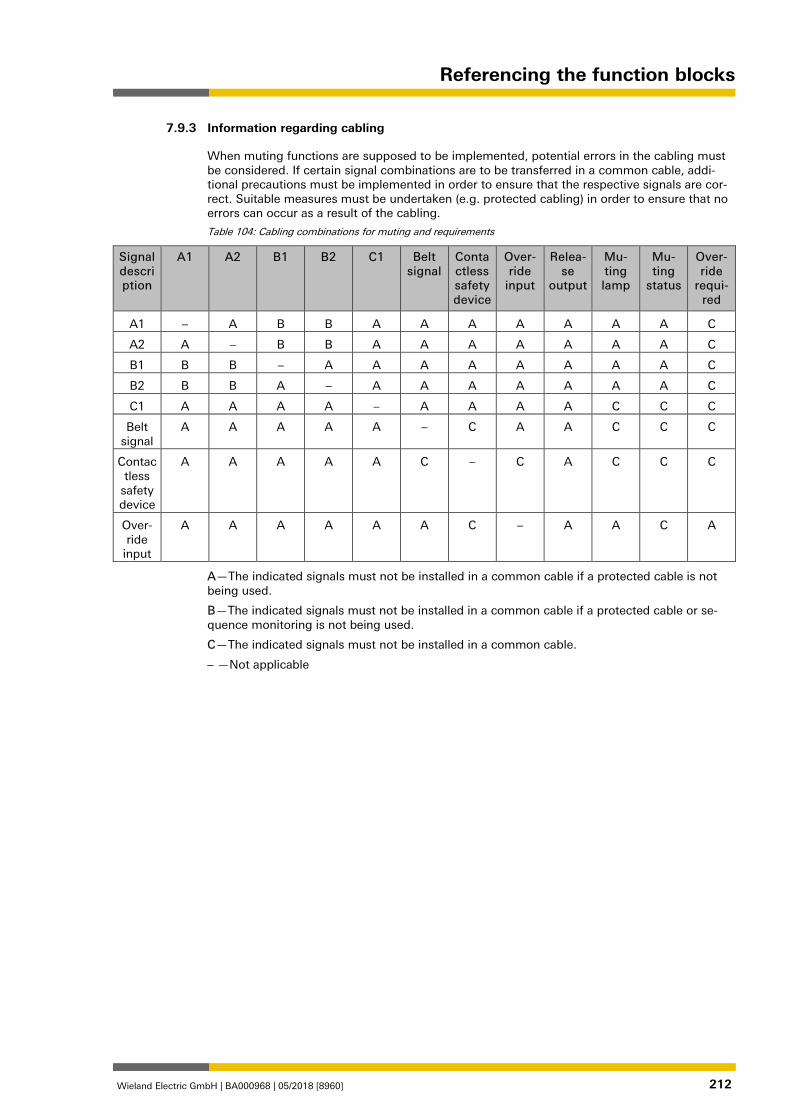
Referencing the function blocks
Wieland Electric GmbH | BA000968 | 05/2018 [8960] 212
Information regarding cabling 839821195
When muting functions are supposed to be implemented, potential errors in the cabling must be considered. If certain signal combinations are to be transferred in a common cable, addi-tional precautions must be implemented in order to ensure that the respective signals are cor-rect. Suitable measures must be undertaken (e.g. protected cabling) in order to ensure that no errors can occur as a result of the cabling.
Table 104: Cabling combinations for muting and requirements
Signal description
A1 A2 B1 B2 C1 Belt signal
Contactless safety device
Over-ride
input
Relea-se
output
Mu-ting lamp
Mu-ting
status
Over-ride
requi-red
A1 – A B B A A A A A A A C
A2 A – B B A A A A A A A C
B1 B B – A A A A A A A A C
B2 B B A – A A A A A A A C
C1 A A A A – A A A A C C C
Belt signal
A A A A A – C A A C C C
Contactless
safety device
A A A A A C – C A C C C
Over-ride
input
A A A A A A C – A A C A
A—The indicated signals must not be installed in a common cable if a protected cable is not being used.
B—The indicated signals must not be installed in a common cable if a protected cable or se-quence monitoring is not being used.
C—The indicated signals must not be installed in a common cable.
– —Not applicable
7.9.3
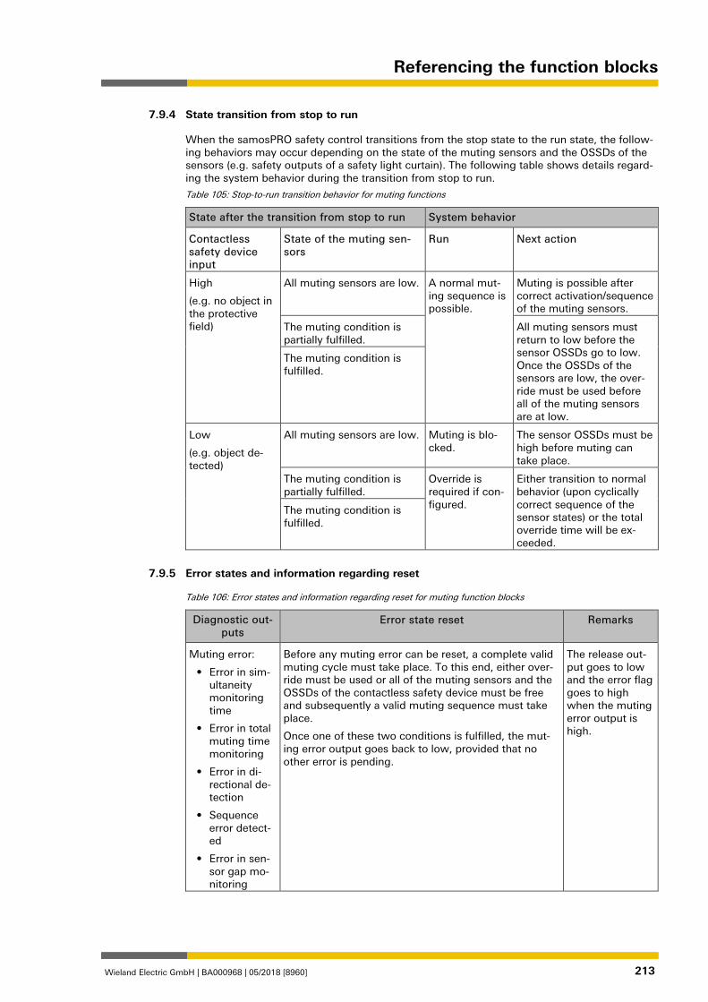
Referencing the function blocks
Wieland Electric GmbH | BA000968 | 05/2018 [8960] 213
State transition from stop to run 839822731
When the samosPRO safety control transitions from the stop state to the run state, the follow-ing behaviors may occur depending on the state of the muting sensors and the OSSDs of the sensors (e.g. safety outputs of a safety light curtain). The following table shows details regard-ing the system behavior during the transition from stop to run.
Table 105: Stop-to-run transition behavior for muting functions
State after the transition from stop to run System behavior
Contactless safety device input
State of the muting sen-sors
Run Next action
High
(e.g. no object in the protective field)
All muting sensors are low. A normal mut-ing sequence is possible.
Muting is possible after correct activation/sequence of the muting sensors.
The muting condition is partially fulfilled.
All muting sensors must return to low before the sensor OSSDs go to low. Once the OSSDs of the sensors are low, the over-ride must be used before all of the muting sensors are at low.
The muting condition is fulfilled.
Low
(e.g. object de-tected)
All muting sensors are low. Muting is blo-cked.
The sensor OSSDs must be high before muting can take place.
The muting condition is partially fulfilled.
Override is required if con-figured.
Either transition to normal behavior (upon cyclically correct sequence of the sensor states) or the total override time will be ex-ceeded.
The muting condition is fulfilled.
Error states and information regarding reset 839823755
Table 106: Error states and information regarding reset for muting function blocks
Diagnostic out-puts
Error state reset Remarks
Muting error:
• Error in sim-ultaneity monitoring time
• Error in total muting time monitoring
• Error in di-rectional de-tection
• Sequence error detect-ed
• Error in sen-sor gap mo-nitoring
Before any muting error can be reset, a complete valid muting cycle must take place. To this end, either over-ride must be used or all of the muting sensors and the OSSDs of the contactless safety device must be free and subsequently a valid muting sequence must take place.
Once one of these two conditions is fulfilled, the mut-ing error output goes back to low, provided that no other error is pending.
The release out-put goes to low and the error flag goes to high when the muting error output is high.
7.9.4
7.9.5
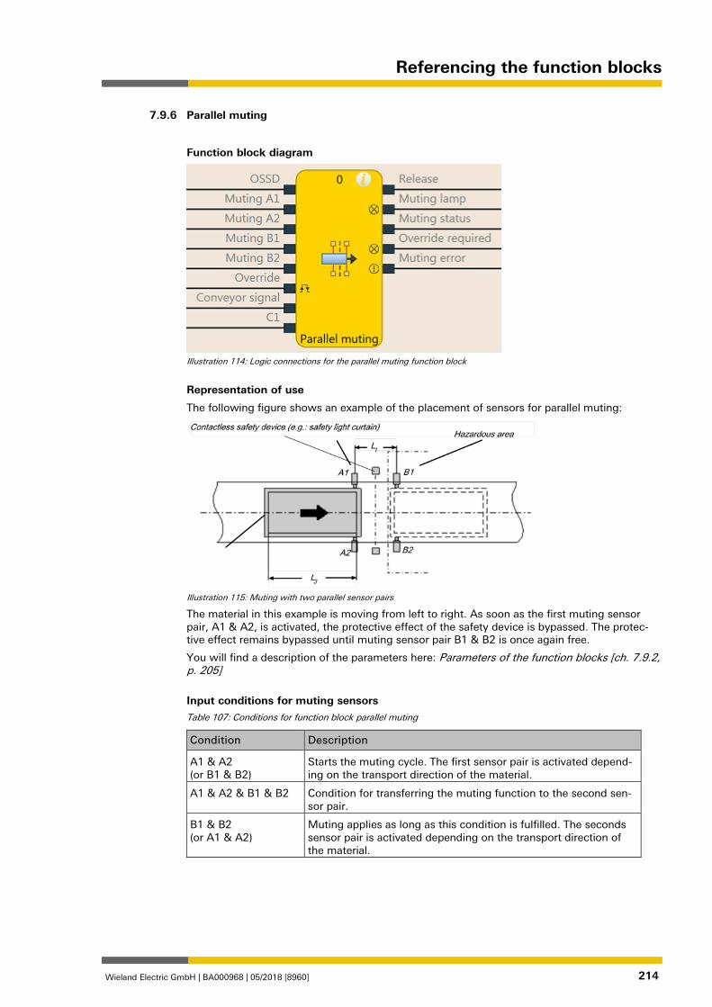
Referencing the function blocks
Wieland Electric GmbH | BA000968 | 05/2018 [8960] 214
Parallel muting 1176781707
Function block diagram
Illustration 114: Logic connections for the parallel muting function block
Representation of use
The following figure shows an example of the placement of sensors for parallel muting:
Illustration 115: Muting with two parallel sensor pairs
The material in this example is moving from left to right. As soon as the first muting sensor pair, A1 & A2, is activated, the protective effect of the safety device is bypassed. The protec-tive effect remains bypassed until muting sensor pair B1 & B2 is once again free.
You will find a description of the parameters here: Parameters of the function blocks [ch. 7.9.2, p. 205]
Input conditions for muting sensors Table 107: Conditions for function block parallel muting
Condition Description
A1 & A2 (or B1 & B2)
Starts the muting cycle. The first sensor pair is activated depend-ing on the transport direction of the material.
A1 & A2 & B1 & B2 Condition for transferring the muting function to the second sen-sor pair.
B1 & B2 (or A1 & A2)
Muting applies as long as this condition is fulfilled. The seconds sensor pair is activated depending on the transport direction of the material.
7.9.6
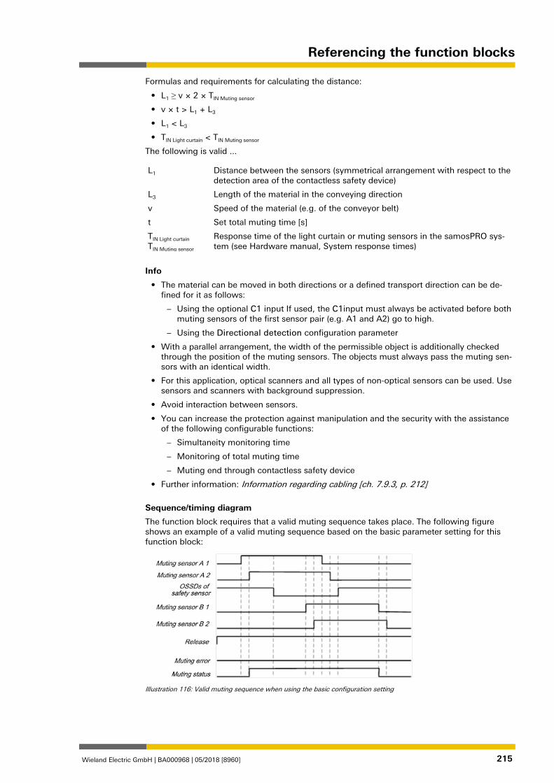
Referencing the function blocks
Wieland Electric GmbH | BA000968 | 05/2018 [8960] 215
Formulas and requirements for calculating the distance:
• L1 ≥ v × 2 × TIN Muting sensor
• v × t > L1 + L3
• L1 < L3
• TIN Light curtain < TIN Muting sensor
The following is valid ...
L1 Distance between the sensors (symmetrical arrangement with respect to the detection area of the contactless safety device)
L3 Length of the material in the conveying direction
v Speed of the material (e.g. of the conveyor belt)
t Set total muting time [s]
TIN Light curtain TIN Muting sensor
Response time of the light curtain or muting sensors in the samosPRO sys-tem (see Hardware manual, System response times)
Info
• The material can be moved in both directions or a defined transport direction can be de-fined for it as follows:
– Using the optional C1 input If used, the C1input must always be activated before both muting sensors of the first sensor pair (e.g. A1 and A2) go to high.
– Using the Directional detection configuration parameter
• With a parallel arrangement, the width of the permissible object is additionally checked through the position of the muting sensors. The objects must always pass the muting sen-sors with an identical width.
• For this application, optical scanners and all types of non-optical sensors can be used. Use sensors and scanners with background suppression.
• Avoid interaction between sensors.
• You can increase the protection against manipulation and the security with the assistance of the following configurable functions:
– Simultaneity monitoring time
– Monitoring of total muting time
– Muting end through contactless safety device
• Further information: Information regarding cabling [ch. 7.9.3, p. 212]
Sequence/timing diagram
The function block requires that a valid muting sequence takes place. The following figure shows an example of a valid muting sequence based on the basic parameter setting for this function block:
Illustration 116: Valid muting sequence when using the basic configuration setting
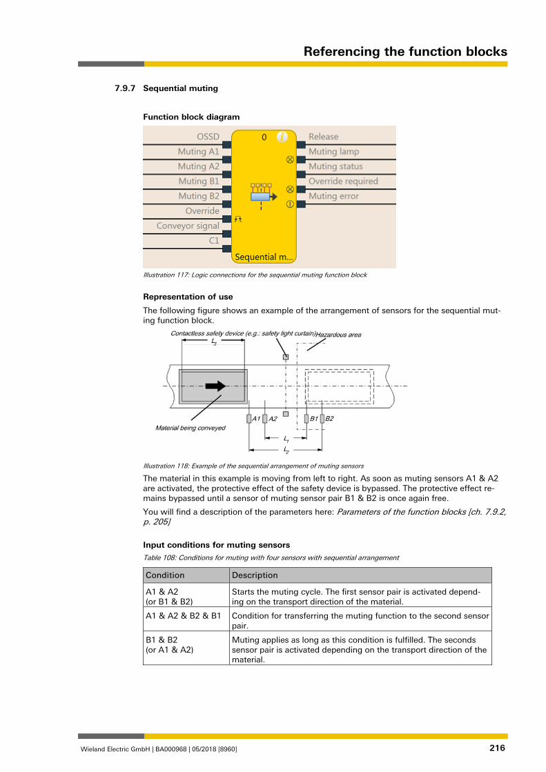
Referencing the function blocks
Wieland Electric GmbH | BA000968 | 05/2018 [8960] 216
Sequential muting 1176830859
Function block diagram
Illustration 117: Logic connections for the sequential muting function block
Representation of use
The following figure shows an example of the arrangement of sensors for the sequential mut-ing function block.
Illustration 118: Example of the sequential arrangement of muting sensors
The material in this example is moving from left to right. As soon as muting sensors A1 & A2 are activated, the protective effect of the safety device is bypassed. The protective effect re-mains bypassed until a sensor of muting sensor pair B1 & B2 is once again free.
You will find a description of the parameters here: Parameters of the function blocks [ch. 7.9.2, p. 205]
Input conditions for muting sensors Table 108: Conditions for muting with four sensors with sequential arrangement
Condition Description
A1 & A2 (or B1 & B2)
Starts the muting cycle. The first sensor pair is activated depend-ing on the transport direction of the material.
A1 & A2 & B2 & B1 Condition for transferring the muting function to the second sensor pair.
B1 & B2 (or A1 & A2)
Muting applies as long as this condition is fulfilled. The seconds sensor pair is activated depending on the transport direction of the material.
7.9.7
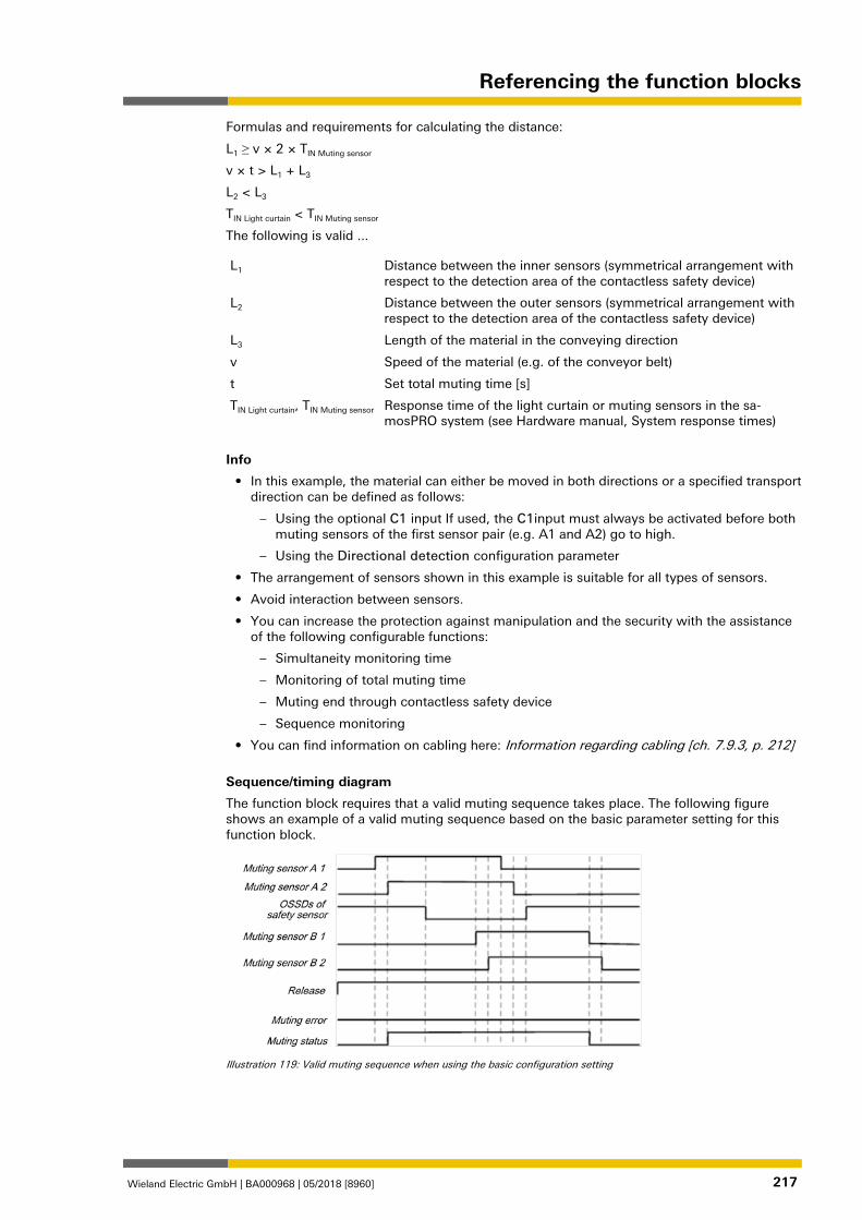
Referencing the function blocks
Wieland Electric GmbH | BA000968 | 05/2018 [8960] 217
Formulas and requirements for calculating the distance:
L1 ≥ v × 2 × TIN Muting sensor
v × t > L1 + L3
L2 < L3
TIN Light curtain < TIN Muting sensor
The following is valid ...
L1 Distance between the inner sensors (symmetrical arrangement with respect to the detection area of the contactless safety device)
L2 Distance between the outer sensors (symmetrical arrangement with respect to the detection area of the contactless safety device)
L3 Length of the material in the conveying direction
v Speed of the material (e.g. of the conveyor belt)
t Set total muting time [s]
TIN Light curtain, TIN Muting sensor Response time of the light curtain or muting sensors in the sa-mosPRO system (see Hardware manual, System response times)
Info
• In this example, the material can either be moved in both directions or a specified transport direction can be defined as follows:
– Using the optional C1 input If used, the C1input must always be activated before both muting sensors of the first sensor pair (e.g. A1 and A2) go to high.
– Using the Directional detection configuration parameter
• The arrangement of sensors shown in this example is suitable for all types of sensors.
• Avoid interaction between sensors.
• You can increase the protection against manipulation and the security with the assistance of the following configurable functions:
– Simultaneity monitoring time
– Monitoring of total muting time
– Muting end through contactless safety device
– Sequence monitoring
• You can find information on cabling here: Information regarding cabling [ch. 7.9.3, p. 212]
Sequence/timing diagram
The function block requires that a valid muting sequence takes place. The following figure shows an example of a valid muting sequence based on the basic parameter setting for this function block.
Illustration 119: Valid muting sequence when using the basic configuration setting
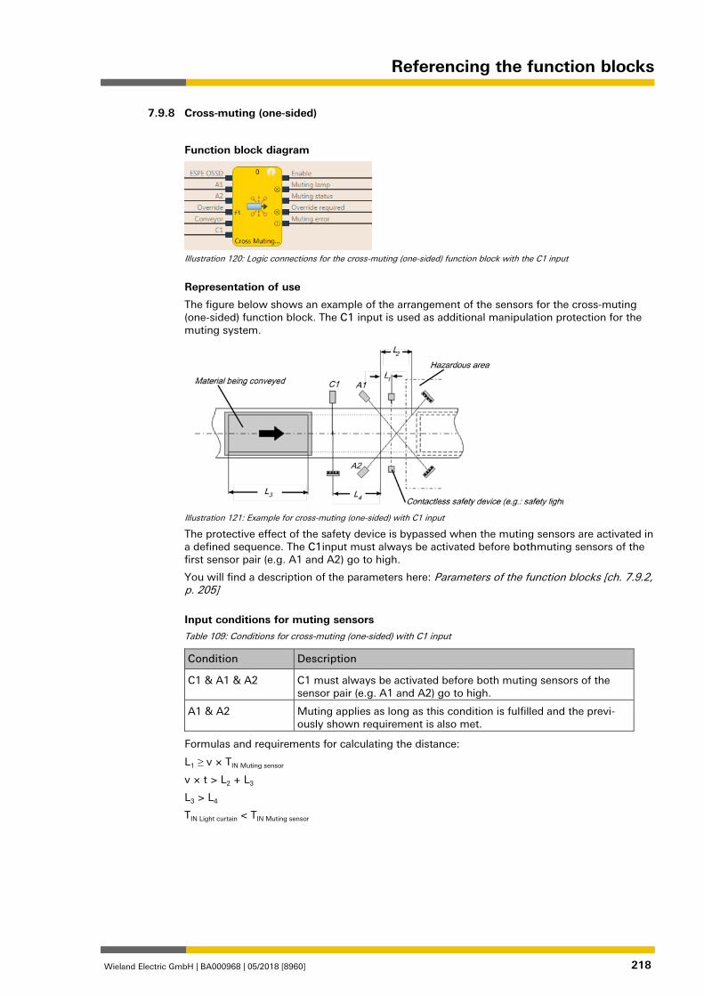
Referencing the function blocks
Wieland Electric GmbH | BA000968 | 05/2018 [8960] 218
Cross-muting (one-sided) 1176895755
Function block diagram
Illustration 120: Logic connections for the cross-muting (one-sided) function block with the C1 input
Representation of use
The figure below shows an example of the arrangement of the sensors for the cross-muting (one-sided) function block. The C1 input is used as additional manipulation protection for the muting system.
Illustration 121: Example for cross-muting (one-sided) with C1 input
The protective effect of the safety device is bypassed when the muting sensors are activated in a defined sequence. The C1input must always be activated before bothmuting sensors of the first sensor pair (e.g. A1 and A2) go to high.
You will find a description of the parameters here: Parameters of the function blocks [ch. 7.9.2, p. 205]
Input conditions for muting sensors Table 109: Conditions for cross-muting (one-sided) with C1 input
Condition Description
C1 & A1 & A2 C1 must always be activated before both muting sensors of the sensor pair (e.g. A1 and A2) go to high.
A1 & A2 Muting applies as long as this condition is fulfilled and the previ-ously shown requirement is also met.
Formulas and requirements for calculating the distance:
L1 ≥ v × TIN Muting sensor
v × t > L2 + L3
L3 > L4
TIN Light curtain < TIN Muting sensor
7.9.8
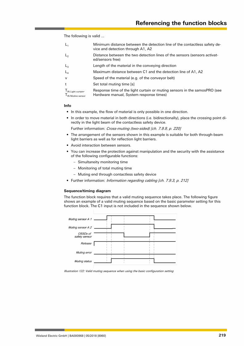
Referencing the function blocks
Wieland Electric GmbH | BA000968 | 05/2018 [8960] 219
The following is valid ...
L1 Minimum distance between the detection line of the contactless safety de-vice and detection through A1, A2
L2 Distance between the two detection lines of the sensors (sensors activat-ed/sensors free)
L3 Length of the material in the conveying direction
L4 Maximum distance between C1 and the detection line of A1, A2
v Speed of the material (e.g. of the conveyor belt)
t Set total muting time [s]
TIN Light curtain, TIN Muting sensor
Response time of the light curtain or muting sensors in the samosPRO (see Hardware manual, System response times)
Info
• In this example, the flow of material is only possible in one direction.
• In order to move material in both directions (i.e. bidirectionally), place the crossing point di-rectly in the light beam of the contactless safety device.
Further information: Cross-muting (two-sided) [ch. 7.9.9, p. 220]
• The arrangement of the sensors shown in this example is suitable for both through-beam light barriers as well as for reflection light barriers.
• Avoid interaction between sensors.
• You can increase the protection against manipulation and the security with the assistance of the following configurable functions:
– Simultaneity monitoring time
– Monitoring of total muting time
– Muting end through contactless safety device
• Further information: Information regarding cabling [ch. 7.9.3, p. 212]
Sequence/timing diagram
The function block requires that a valid muting sequence takes place. The following figure shows an example of a valid muting sequence based on the basic parameter setting for this function block. The C1 input is not included in the sequence shown below.
Illustration 122: Valid muting sequence when using the basic configuration setting
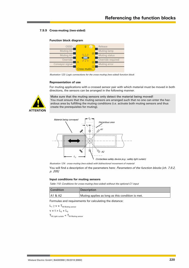
Referencing the function blocks
Wieland Electric GmbH | BA000968 | 05/2018 [8960] 220
Cross-muting (two-sided) 1176937099
Function block diagram
Illustration 123: Logic connections for the cross-muting (two-sided) function block
Representation of use
For muting applications with a crossed sensor pair with which material must be moved in both directions, the sensors can be arranged in the following manner.
ATTENTION
Make sure that the muting sensors only detect the material being moved! You must ensure that the muting sensors are arranged such that no one can enter the haz-ardous area by fulfilling the muting conditions (i.e. activate both muting sensors and thus create the prerequisites for muting).
Illustration 124: cross-muting (two-sided) with bidirectional movement of material
You will find a description of the parameters here: Parameters of the function blocks [ch. 7.9.2, p. 205]
Input conditions for muting sensors Table 110: Conditions for cross-muting (two-sided) without the optional C1 input
Condition Description
A1 & A2 Muting applies as long as this condition is met.
Formulas and requirements for calculating the distance:
L1 ≥ v × TIN Muting sensor
v × t > L2 + L3
TIN Light curtain < TIN Muting sensor
7.9.9
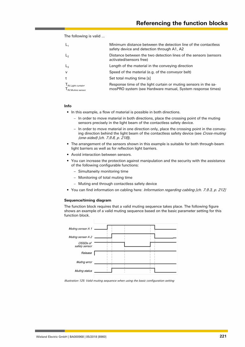
Referencing the function blocks
Wieland Electric GmbH | BA000968 | 05/2018 [8960] 221
The following is valid ...
L1 Minimum distance between the detection line of the contactless safety device and detection through A1, A2
L2 Distance between the two detection lines of the sensors (sensors activated/sensors free)
L3 Length of the material in the conveying direction
v Speed of the material (e.g. of the conveyor belt)
t Set total muting time [s]
TIN Light curtain, TIN Muting sensor
Response time of the light curtain or muting sensors in the sa-mosPRO system (see Hardware manual, System response times)
Info
• In this example, a flow of material is possible in both directions.
– In order to move material in both directions, place the crossing point of the muting sensors precisely in the light beam of the contactless safety device.
– In order to move material in one direction only, place the crossing point in the convey-ing direction behind the light beam of the contactless safety device (see Cross-muting (one-sided) [ch. 7.9.8, p. 218]).
• The arrangement of the sensors shown in this example is suitable for both through-beam light barriers as well as for reflection light barriers.
• Avoid interaction between sensors.
• You can increase the protection against manipulation and the security with the assistance of the following configurable functions:
– Simultaneity monitoring time
– Monitoring of total muting time
– Muting end through contactless safety device
• You can find information on cabling here: Information regarding cabling [ch. 7.9.3, p. 212]
Sequence/timing diagram
The function block requires that a valid muting sequence takes place. The following figure shows an example of a valid muting sequence based on the basic parameter setting for this function block.
Illustration 125: Valid muting sequence when using the basic configuration setting
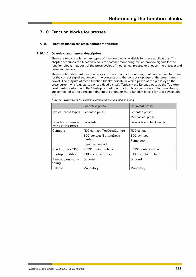
Referencing the function blocks
Wieland Electric GmbH | BA000968 | 05/2018 [8960] 222
Function blocks for presses 1076723211
Function blocks for press contact monitoring 1076724747
1076726283
Overview and general description
There are two complementary types of function blocks available for press applications. This chapter describes the function blocks for contact monitoring, which provide signals for the function blocks that control the press cycles of mechanical presses (e.g. eccentric presses) and universal presses.
There are two different function blocks for press contact monitoring that can be used to moni-tor the correct signal sequence of the contacts and the correct stoppage of the press (ramp-down). The outputs of these function blocks indicate in which phase of the press cycle the press currently is (e.g. startup or top dead center). Typically the Release output, the Top (top dead center) output, and the Startup output of a function block for press contact monitoring are connected to the corresponding inputs of one or more function blocks for press cycle con-trol.
Table 111: Overview of the function blocks for press contact monitoring
Eccentric press Universal press
Typical press types Eccentric press Eccentric press
Mechanical press
Direction of move-ment of the press
Forwards Forwards and backwards
Contacts TDC contact (TopDeadCenter)
BDC contact (BottomDead-Center)
Dynamic contact
TDC contact
BDC contact
Ramp-down
Condition for TDC If TDC contact = high If TDC contact = low
Startup condition If BDC contact = high If BDC contact = high
Ramp-down moni-toring
Optional Optional
Release Mandatory Mandatory
1076727819
7.10
7.10.1
7.10.1.1
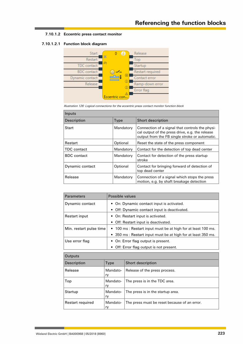
Referencing the function blocks
Wieland Electric GmbH | BA000968 | 05/2018 [8960] 223
Eccentric press contact monitor 1076729355
Function block diagram
Illustration 126: Logical connections for the eccentric press contact monitor function block
Inputs
Description Type Short description
Start Mandatory Connection of a signal that controls the physi-cal output of the press drive, e.g. the release output from the FB single stroke or automatic.
Restart Optional Reset the state of the press component
TDC contact Mandatory Contact for the detection of top dead center
BDC contact Mandatory Contact for detection of the press startup stroke
Dynamic contact Optional Contact for bringing forward of detection of top dead center
Release Mandatory Connection of a signal which stops the press motion, e.g. by shaft breakage detection
Parameters Possible values
Dynamic contact • On: Dynamic contact input is activated.
• Off: Dynamic contact input is deactivated.
Restart input • On: Restart input is activated.
• Off: Restart input is deactivated.
Min. restart pulse time • 100 ms : Restart input must be at high for at least 100 ms.
• 350 ms : Restart input must be at high for at least 350 ms.
Use error flag • On: Error flag output is present.
• Off: Error flag output is not present.
Outputs
Description Type Short description
Release Mandato-ry
Release of the press process.
Top Mandato-ry
The press is in the TDC area.
Startup Mandato-ry
The press is in the startup area.
Restart required Mandato-ry
The press must be reset because of an error.
7.10.1.2
7.10.1.2.1
Referencing the function blocks
Wieland Electric GmbH | BA000968 | 05/2018 [8960] 224
Outputs
Description Type Short description
Contact error Mandato-ry
Invalid sequence of the contact signals.
Ramp-down error Mandato-ry
A ramp-down error was detected.
Error flag Optional A contact error or ramp-down error is present.
1076732043
General description
The Eccentric Press Contact Monitor function block (FB) can be used for certain types of me-chanical presses (e.g. eccentric presses). Besides the Start input, the minimum configuration requires the inputs TDC contact, BDC contact and release. The remaining inputs are optional.
The function block has the special feature that the Release output is set to High from the out-set when the inputs are not set up in a configuration that results in an error. The signal se-quence at the Start input is evaluated if a falling edge at the TDC contact input is detected and the BDC contact input is low (the press is leaving the top dead center).
Another special feature is that the Restart required output can be high even if the Restart in-put is not present. A reset of this output is then possible only by a stop/run transition of the samosPRO.
A typical sequence of the function block is that the press is at top dead center (TDC contact input high) and in the first step therefore the Release and Top outputs are high. In this state the Start input must either remain high or go through a high-low sequence. The press now goes through its stroke motion so that the next TDC contact input is low, because the press is leaving the top dead center. If the Start input has previously failed to changed its state as specified, the FB enters the Ramp-down error and the associated output is high, the Release output is low and Restart required high. If there is no error, then the press continues to oper-ate and eventually reaches the bottom dead center to then start the startup stroke. This is re-ported by the BDC contact input, which is high at this point. The Startup output is also high. If the press approaches the top dead center, the TDC contact input is again high, the Top out-put is high, the Startup output is low. Shortly afterwards the BDC contact input is low and the sequence can begin again. If the contacts do not respond as specified, then the Contact error is detected and the associated output is high, Release is low, and Restart required high. 1076733579
Parameters of the function block Table 112: Parameters of the eccentric press contact monitor function block
Parameters Possible values
Dynamic contact • On: Dynamic contact input is activated.
• Off: Dynamic contact input is deactivated.
Restart input • On: Restart input is activated.
• Off: Restart input is deactivated.
Min. restart pulse time • 100 ms: Restart input must be at high for at least 100 ms.
• 350 ms: Restart input must be at high for at least 350 ms.
Use error flag • On: Error flag output is present.
• Off: Error flag output is not present.
Dynamic contact parameter
The Dynamic contact parameter specifies whether the start of the TDC phase can be ad-vanced by a falling edge at the Dynamic contact input.
If the Dynamic contact parameter is set to On, then the start of the TDC phase can be ad-vanced by a falling edge at the Dynamic contact input. In this case the BDC contact and TDC contact inputs must behave as described in the General description section. The falling edge at the Dynamic contact input ends the startup phase, the Startup output is low, the Top out-put is high.
7.10.1.2.2
7.10.1.2.3
Referencing the function blocks
Wieland Electric GmbH | BA000968 | 05/2018 [8960] 225
Restart input parameter
This parameter activates the Restart input. If the Restart input is present, then errors can be reset by a valid restart sequence. A valid restart sequence consists of a low-high-low sequence on the Restart input with a high time of 100 ms or 350 ms, depending on the configuration. Shorter high times or high times longer than 30 seconds are ignored.
Min. restart pulse time parameter
A restart sequence (low-high-low Restart input) is only valid if the Restart input was set to high for at least 100 ms or 350 ms. This value is set with the Min. restart pulse time parame-ter.
Use error flag parameter
This parameter can make an additional output available that is set to high when the function block enters an error state. 1076735115
Function block inputs Table 113: Inputs of the eccentric press contact monitor function block
Description Type Short description
Start Mandatory Connection of a signal that controls the physi-cal output of the press drive, e.g. the release output from the FB single stroke or automatic.
Restart Optional Reset the state of the press component
TDC contact Mandatory Contact for the detection of top dead center
BDC contact Mandatory Contact for detection of the press startup stroke
Dynamic contact Optional Contact for bringing forward of detection of top dead center
Release Mandatory Connection of a signal which stops the press motion, e.g. by shaft breakage detection
Start input
The Start input is used to monitor the press ramp-down. The input must be connected to the signal that controls the physical output of the press drive so that the FB can detect whether the press is currently running or has been stopped.
NOTICE Do not connect any physical input signals to the Start input. Use a CPU flag to connect the signal that controls the physical output for the press drive.
Restart input
Using the Restart input it is possible to reset errors using a valid restart sequence.
A valid restart sequence at the Restart input corresponds to the low-high-low transition with a pulse duration of at least 100 ms or 350 ms and a maximum of 30 s. Shorter or longer pulses are ignored.
If the Restart input is deactivated, then an error can only be reset by stopping execution of the logic program, e.g. by briefly switching off and back on again or by switching the system from the run state to the stop state and then back to the run state using samosPLAN 6.
ATTENTION
Make sure that the transitions of the signals for reset meet the requirements! When there is a short-circuit to high (to 24 V DC) at a physical input, the evaluated signal can have a pulse when the signal is reset as a result of short-circuit detection. If this type of pulse can lead to a hazard-inducing state in the machine, then the following points should be not-ed: • Ensure that the cable routing is protected for the signal lines (due to cross-connection
with other signal lines). • No short-circuit detection, i.e. do not reference to test outputs.
7.10.1.2.4
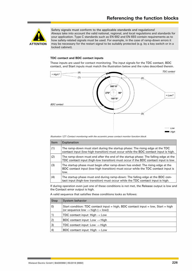
Referencing the function blocks
Wieland Electric GmbH | BA000968 | 05/2018 [8960] 226
ATTENTION
Safety signals must conform to the applicable standards and regulations! Always take into account the valid national, regional, and local regulations and standards for your application. Type C standards such as EN 692 and EN 693 contain requirements as to how safety-related signals must be used. For example, in the case of ramp-down errors it may be necessary for the restart signal to be suitably protected (e.g. by a key switch or in a locked cabinet).
TDC contact and BDC contact inputs
These inputs are used for contact monitoring. The input signals for the TDC contact, BDC contact, and Start inputs must match the illustration below and the rules described therein.
Illustration 127: Contact monitoring with the eccentric press contact monitor function block
Item Explanation
(1) The ramp-down must start during the startup phase: The rising edge at the TDC contact input (low-high transition) must occur while the BDC contact input is high.
(2) The ramp-down must end after the end of the startup phase: The falling edge at the TDC contact input (high-low transition) must occur if the BDC contact input is low.
(3) The startup phase must begin after ramp-down has ended: The rising edge at the BDC contact input (low-high transition) must occur while the TDC contact input is low.
(4) The startup phase must end during ramp-down: The falling edge at the BDC con-tact input (high-low transition) must occur while the TDC contact input is high.
If during operation even just one of these conditions is not met, the Release output is low and the Contact error output is high.
A valid sequence that satisfies these conditions looks as follows:
Step System behavior
0) Start condition: TDC contact input = high, BDC contact input = low, Start = high (or sequence low → high (→ low))
1) TDC contact input: High → Low
2) BDC contact input: Low → High
3) TDC contact input: Low → High
4) BDC contact input: High → Low
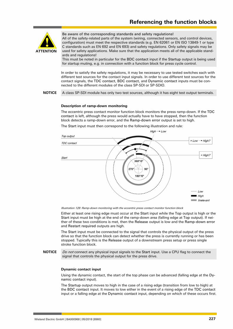
Referencing the function blocks
Wieland Electric GmbH | BA000968 | 05/2018 [8960] 227
ATTENTION
Be aware of the corresponding standards and safety regulations! All of the safety-related parts of the system (wiring, connected sensors, and control devices, configuration) must meet the respective standards (e.g. EN 62061 or EN ISO 13849-1 or type C standards such as EN 692 and EN 693) and safety regulations. Only safety signals may be used for safety applications. Make sure that the application meets all of the applicable stand-ards and regulations! This must be noted in particular for the BDC contact input if the Startup output is being used for startup muting, e.g. in connection with a function block for press cycle control.
In order to satisfy the safety regulations, it may be necessary to use tested switches each with different test sources for the contact input signals. In order to use different test sources for the contact signals, the TDC contact, BDC contact, and Dynamic contact inputs must be con-nected to the different modules of the class SP-SDI or SP-SDIO.
NOTICE A class SP-SDI module has only two test sources, although it has eight test output terminals.
Description of ramp-down monitoring
The eccentric press contact monitor function block monitors the press ramp-down. If the TDC contact is left, although the press would actually have to have stopped, then the function block detects a ramp-down error, and the Ramp-down error output is set to high.
The Start input must then correspond to the following illustration and rule:
Illustration 128: Ramp-down monitoring with the eccentric press contact monitor function block
Either at least one rising edge must occur at the Start input while the Top output is high or the Start input must be high at the end of the ramp-down area (falling edge at Top output). If nei-ther of these two conditions is met, then the Release output is low and the Ramp-down error and Restart required outputs are high.
The Start input must be connected to the signal that controls the physical output of the press drive so that the function block can detect whether the press is currently running or has been stopped. Typically this is the Release output of a downstream press setup or press single stroke function block.
NOTICE Do not connect any physical input signals to the Start input. Use a CPU flag to connect the signal that controls the physical output for the press drive.
Dynamic contact input
Using the dynamic contact, the start of the top phase can be advanced (falling edge at the Dy-namic contact input).
The Startup output moves to high in the case of a rising edge (transition from low to high) at the BDC contact input. It moves to low either in the event of a rising edge of the TDC contact input or a falling edge at the Dynamic contact input, depending on which of these occurs first.
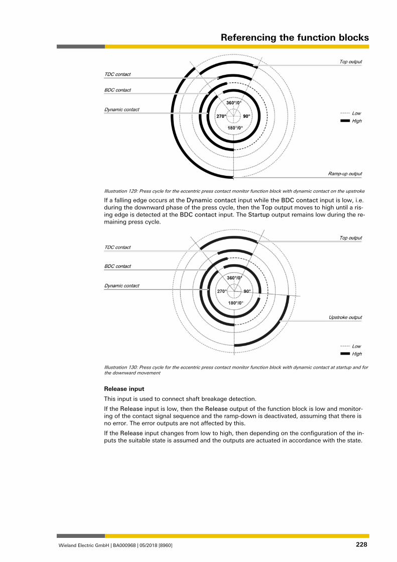
Referencing the function blocks
Wieland Electric GmbH | BA000968 | 05/2018 [8960] 228
Illustration 129: Press cycle for the eccentric press contact monitor function block with dynamic contact on the upstroke
If a falling edge occurs at the Dynamic contact input while the BDC contact input is low, i.e. during the downward phase of the press cycle, then the Top output moves to high until a ris-ing edge is detected at the BDC contact input. The Startup output remains low during the re-maining press cycle.
Illustration 130: Press cycle for the eccentric press contact monitor function block with dynamic contact at startup and for the downward movement
Release input
This input is used to connect shaft breakage detection.
If the Release input is low, then the Release output of the function block is low and monitor-ing of the contact signal sequence and the ramp-down is deactivated, assuming that there is no error. The error outputs are not affected by this.
If the Release input changes from low to high, then depending on the configuration of the in-puts the suitable state is assumed and the outputs are actuated in accordance with the state. 1076742795
Referencing the function blocks
Wieland Electric GmbH | BA000968 | 05/2018 [8960] 229
Function block outputs Table 114: Outputs of the eccentric press contact monitor function block
Description Type Short description
Release Mandato-ry
Release of the press process.
Top Mandato-ry
The press is in the TDC area.
Startup Mandato-ry
The press is in the startup area.
Restart required Mandato-ry
The press must be reset because of an error.
Contact error Mandato-ry
Invalid sequence of the contact signals.
Ramp-down error Mandato-ry
A ramp-down error was detected.
Error flag Optional A contact error or ramp-down error is present.
Release output
The Release output is used to stop the press and is connected to another supplementary press function block such as press setup or press single stroke. If no error has been detected, the Release output of the function block is high.
If an error is detected in the sequence of contact signals, the Release output moves to low, the affected error output moves to high, and the Reset required output moves to high. A valid re-start sequence at the Restart input is then required.
The Release output also moves to low when the Release input is deactivated.
Top output
The Top output moves to high in the event of a rising edge at the TDC contact input or a fall-ing edge at the Dynamic contact input (the Release input cannot have a falling edge), de-pending on which of them occurs first. The Top output moves to low in the event of a falling edge at the TDC contact input.
The Top output is typically used to stop the press and is connected to another supplementary press function block such as press setup or press single stroke.
Startup output
The Startup output is typically connected to another supplementary press function block such as press setup or press single stroke. It can also be used to trigger startup muting.
This function block sets the Startup and Top outputs based on the state changes at the con-tact inputs. If the function block detects an error, both outputs are set to low.
Restart required output
The Restart required output is high if a valid restart sequence is expected at the Restart input. This output is set back to low only after a valid restart sequence and the Release output can-not be high while this output is high. A valid restart sequence is described in the Restart input and Min. restart pulse time parameter sections.
Contact error output
This output is set to high when the predetermined sequence of the contact states is not ad-hered to. The valid sequences were described in the TDC contact input, BDC contact input, and Dynamic contact input sections. Above all, activation of the Dynamic contact parameter changes the contact sequence fundamentally. All variants of an invalid sequence lead to errors and the Contact error output is set to high.
7.10.1.2.5
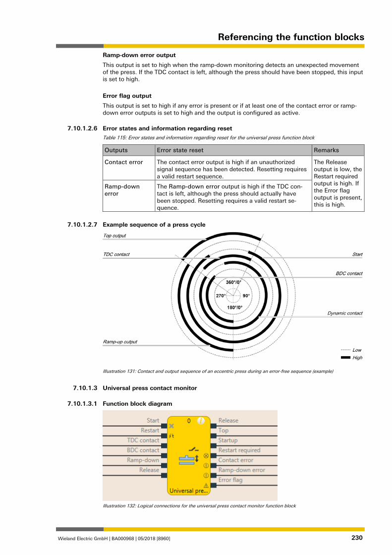
Referencing the function blocks
Wieland Electric GmbH | BA000968 | 05/2018 [8960] 230
Ramp-down error output
This output is set to high when the ramp-down monitoring detects an unexpected movement of the press. If the TDC contact is left, although the press should have been stopped, this input is set to high.
Error flag output
This output is set to high if any error is present or if at least one of the contact error or ramp-down error outputs is set to high and the output is configured as active. 1076744331
Error states and information regarding reset Table 115: Error states and information regarding reset for the universal press function block
Outputs Error state reset Remarks
Contact error The contact error output is high if an unauthorized signal sequence has been detected. Resetting requires a valid restart sequence.
The Release output is low, the Restart required output is high. If the Error flag output is present, this is high.
Ramp-down error
The Ramp-down error output is high if the TDC con-tact is left, although the press should actually have been stopped. Resetting requires a valid restart se-quence.
1119726475
Example sequence of a press cycle
Illustration 131: Contact and output sequence of an eccentric press during an error-free sequence (example)
1076745867
Universal press contact monitor 1076747403
Function block diagram
Illustration 132: Logical connections for the universal press contact monitor function block
7.10.1.2.6
7.10.1.2.7
7.10.1.3
7.10.1.3.1
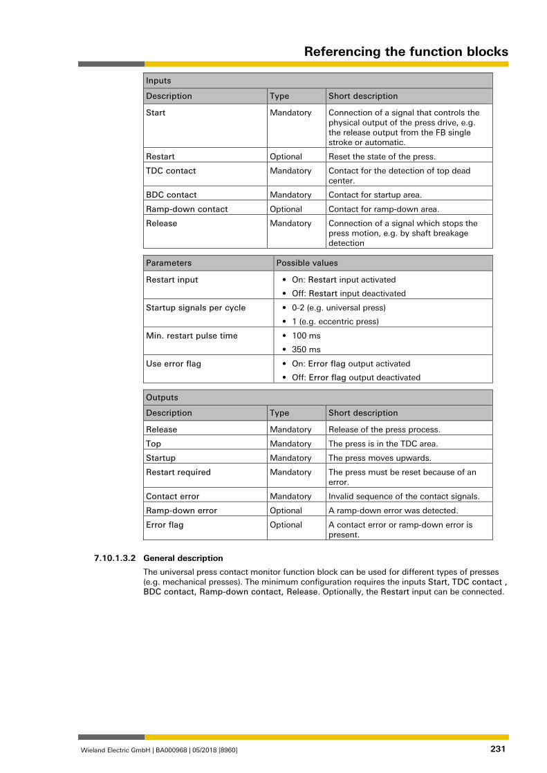
Referencing the function blocks
Wieland Electric GmbH | BA000968 | 05/2018 [8960] 231
Inputs
Description Type Short description
Start Mandatory Connection of a signal that controls the physical output of the press drive, e.g. the release output from the FB single stroke or automatic.
Restart Optional Reset the state of the press.
TDC contact Mandatory Contact for the detection of top dead center.
BDC contact Mandatory Contact for startup area.
Ramp-down contact Optional Contact for ramp-down area.
Release Mandatory Connection of a signal which stops the press motion, e.g. by shaft breakage detection
Parameters Possible values
Restart input • On: Restart input activated
• Off: Restart input deactivated
Startup signals per cycle • 0-2 (e.g. universal press)
• 1 (e.g. eccentric press)
Min. restart pulse time • 100 ms
• 350 ms
Use error flag • On: Error flag output activated
• Off: Error flag output deactivated
Outputs
Description Type Short description
Release Mandatory Release of the press process.
Top Mandatory The press is in the TDC area.
Startup Mandatory The press moves upwards.
Restart required Mandatory The press must be reset because of an error.
Contact error Mandatory Invalid sequence of the contact signals.
Ramp-down error Optional A ramp-down error was detected.
Error flag Optional A contact error or ramp-down error is present.
1076750091
General description
The universal press contact monitor function block can be used for different types of presses (e.g. mechanical presses). The minimum configuration requires the inputs Start, TDC contact , BDC contact, Ramp-down contact, Release. Optionally, the Restart input can be connected.
7.10.1.3.2
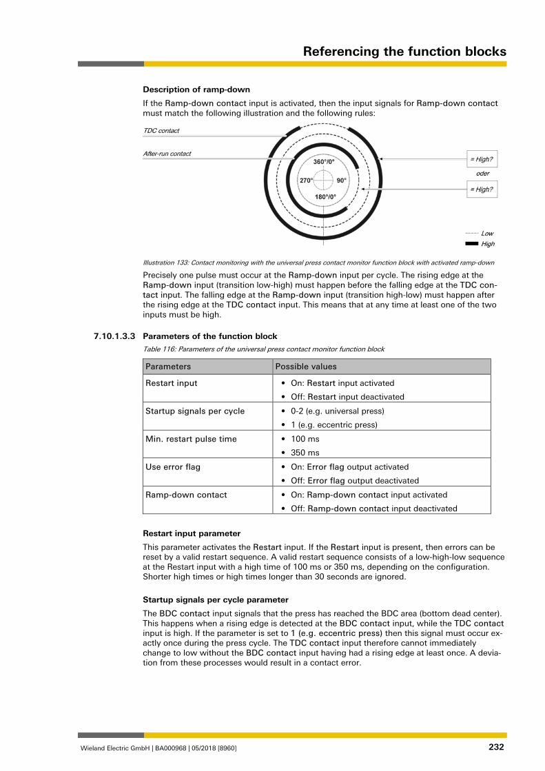
Referencing the function blocks
Wieland Electric GmbH | BA000968 | 05/2018 [8960] 232
Description of ramp-down
If the Ramp-down contact input is activated, then the input signals for Ramp-down contact must match the following illustration and the following rules:
Illustration 133: Contact monitoring with the universal press contact monitor function block with activated ramp-down
Precisely one pulse must occur at the Ramp-down input per cycle. The rising edge at the Ramp-down input (transition low-high) must happen before the falling edge at the TDC con-tact input. The falling edge at the Ramp-down input (transition high-low) must happen after the rising edge at the TDC contact input. This means that at any time at least one of the two inputs must be high. 1076752779
Parameters of the function block Table 116: Parameters of the universal press contact monitor function block
Parameters Possible values
Restart input • On: Restart input activated
• Off: Restart input deactivated
Startup signals per cycle • 0-2 (e.g. universal press)
• 1 (e.g. eccentric press)
Min. restart pulse time • 100 ms
• 350 ms
Use error flag • On: Error flag output activated
• Off: Error flag output deactivated
Ramp-down contact • On: Ramp-down contact input activated
• Off: Ramp-down contact input deactivated
Restart input parameter
This parameter activates the Restart input. If the Restart input is present, then errors can be reset by a valid restart sequence. A valid restart sequence consists of a low-high-low sequence at the Restart input with a high time of 100 ms or 350 ms, depending on the configuration. Shorter high times or high times longer than 30 seconds are ignored.
Startup signals per cycle parameter
The BDC contact input signals that the press has reached the BDC area (bottom dead center). This happens when a rising edge is detected at the BDC contact input, while the TDC contact input is high. If the parameter is set to 1 (e.g. eccentric press) then this signal must occur ex-actly once during the press cycle. The TDC contact input therefore cannot immediately change to low without the BDC contact input having had a rising edge at least once. A devia-tion from these processes would result in a contact error.
7.10.1.3.3
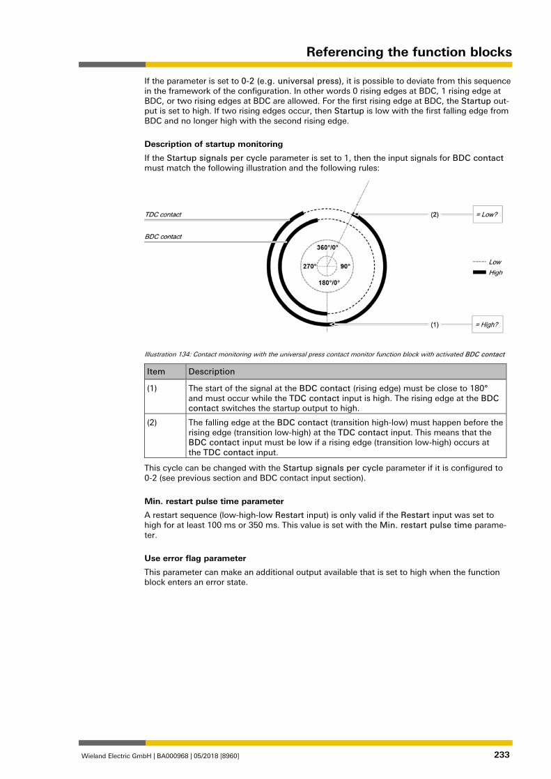
Referencing the function blocks
Wieland Electric GmbH | BA000968 | 05/2018 [8960] 233
If the parameter is set to 0-2 (e.g. universal press), it is possible to deviate from this sequence in the framework of the configuration. In other words 0 rising edges at BDC, 1 rising edge at BDC, or two rising edges at BDC are allowed. For the first rising edge at BDC, the Startup out-put is set to high. If two rising edges occur, then Startup is low with the first falling edge from BDC and no longer high with the second rising edge.
Description of startup monitoring
If the Startup signals per cycle parameter is set to 1, then the input signals for BDC contact must match the following illustration and the following rules:
Illustration 134: Contact monitoring with the universal press contact monitor function block with activated BDC contact
Item Description
(1) The start of the signal at the BDC contact (rising edge) must be close to 180° and must occur while the TDC contact input is high. The rising edge at the BDC contact switches the startup output to high.
(2) The falling edge at the BDC contact (transition high-low) must happen before the rising edge (transition low-high) at the TDC contact input. This means that the BDC contact input must be low if a rising edge (transition low-high) occurs at the TDC contact input.
This cycle can be changed with the Startup signals per cycle parameter if it is configured to 0-2 (see previous section and BDC contact input section).
Min. restart pulse time parameter
A restart sequence (low-high-low Restart input) is only valid if the Restart input was set to high for at least 100 ms or 350 ms. This value is set with the Min. restart pulse time parame-ter.
Use error flag parameter
This parameter can make an additional output available that is set to high when the function block enters an error state.
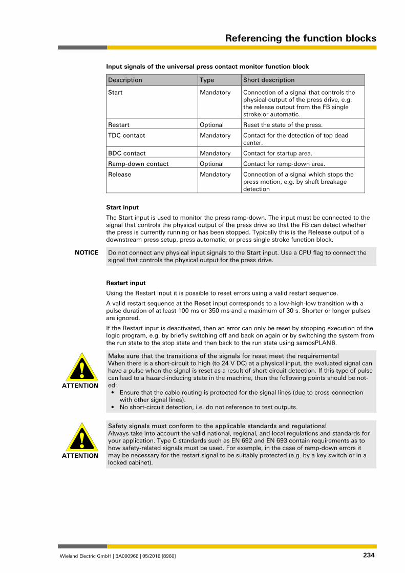
Referencing the function blocks
Wieland Electric GmbH | BA000968 | 05/2018 [8960] 234
Input signals of the universal press contact monitor function block
Description Type Short description
Start Mandatory Connection of a signal that controls the physical output of the press drive, e.g. the release output from the FB single stroke or automatic.
Restart Optional Reset the state of the press.
TDC contact Mandatory Contact for the detection of top dead center.
BDC contact Mandatory Contact for startup area.
Ramp-down contact Optional Contact for ramp-down area.
Release Mandatory Connection of a signal which stops the press motion, e.g. by shaft breakage detection
Start input
The Start input is used to monitor the press ramp-down. The input must be connected to the signal that controls the physical output of the press drive so that the FB can detect whether the press is currently running or has been stopped. Typically this is the Release output of a downstream press setup, press automatic, or press single stroke function block.
NOTICE Do not connect any physical input signals to the Start input. Use a CPU flag to connect the signal that controls the physical output for the press drive.
Restart input
Using the Restart input it is possible to reset errors using a valid restart sequence.
A valid restart sequence at the Reset input corresponds to a low-high-low transition with a pulse duration of at least 100 ms or 350 ms and a maximum of 30 s. Shorter or longer pulses are ignored.
If the Restart input is deactivated, then an error can only be reset by stopping execution of the logic program, e.g. by briefly switching off and back on again or by switching the system from the run state to the stop state and then back to the run state using samosPLAN 6.
ATTENTION
Make sure that the transitions of the signals for reset meet the requirements! When there is a short-circuit to high (to 24 V DC) at a physical input, the evaluated signal can have a pulse when the signal is reset as a result of short-circuit detection. If this type of pulse can lead to a hazard-inducing state in the machine, then the following points should be not-ed: • Ensure that the cable routing is protected for the signal lines (due to cross-connection
with other signal lines). • No short-circuit detection, i.e. do not reference to test outputs.
ATTENTION
Safety signals must conform to the applicable standards and regulations! Always take into account the valid national, regional, and local regulations and standards for your application. Type C standards such as EN 692 and EN 693 contain requirements as to how safety-related signals must be used. For example, in the case of ramp-down errors it may be necessary for the restart signal to be suitably protected (e.g. by a key switch or in a locked cabinet).
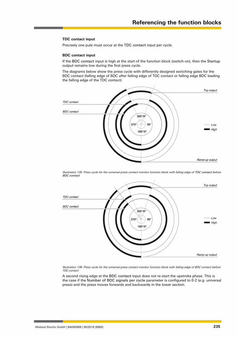
Referencing the function blocks
Wieland Electric GmbH | BA000968 | 05/2018 [8960] 235
TDC contact input
Precisely one pule must occur at the TDC contact input per cycle.
BDC contact input
If the BDC contact input is high at the start of the function block (switch-on), then the Startup output remains low during the first press cycle.
The diagrams below show the press cycle with differently designed switching gates for the BDC contact (falling edge of BDC after falling edge of TDC contact or falling edge BDC leading the falling edge of the TDC contact)
Illustration 135: Press cycle for the universal press contact monitor function block with falling edge of TDC contact before BDC contact
Illustration 136: Press cycle for the universal press contact monitor function block with falling edge of BDC contact before TDC contact
A second rising edge at the BDC contact input does not re-start the upstroke phase. This is the case if the Number of BDC signals per cycle parameter is configured to 0-2 (e.g. universal press) and the press moves forwards and backwards in the lower section.
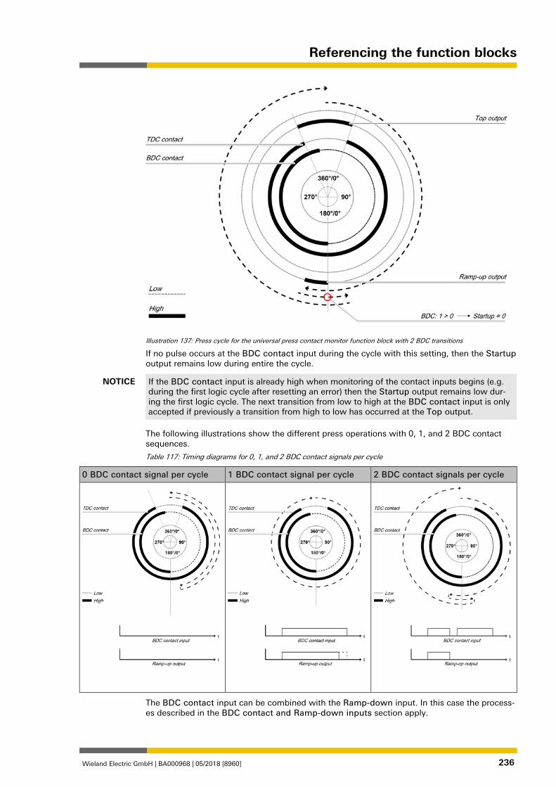
Referencing the function blocks
Wieland Electric GmbH | BA000968 | 05/2018 [8960] 236
Illustration 137: Press cycle for the universal press contact monitor function block with 2 BDC transitions
If no pulse occurs at the BDC contact input during the cycle with this setting, then the Startup output remains low during entire the cycle.
NOTICE If the BDC contact input is already high when monitoring of the contact inputs begins (e.g. during the first logic cycle after resetting an error) then the Startup output remains low dur-ing the first logic cycle. The next transition from low to high at the BDC contact input is only accepted if previously a transition from high to low has occurred at the Top output.
The following illustrations show the different press operations with 0, 1, and 2 BDC contact sequences.
Table 117: Timing diagrams for 0, 1, and 2 BDC contact signals per cycle
0 BDC contact signal per cycle 1 BDC contact signal per cycle 2 BDC contact signals per cycle
The BDC contact input can be combined with the Ramp-down input. In this case the process-es described in the BDC contact and Ramp-down inputs section apply.
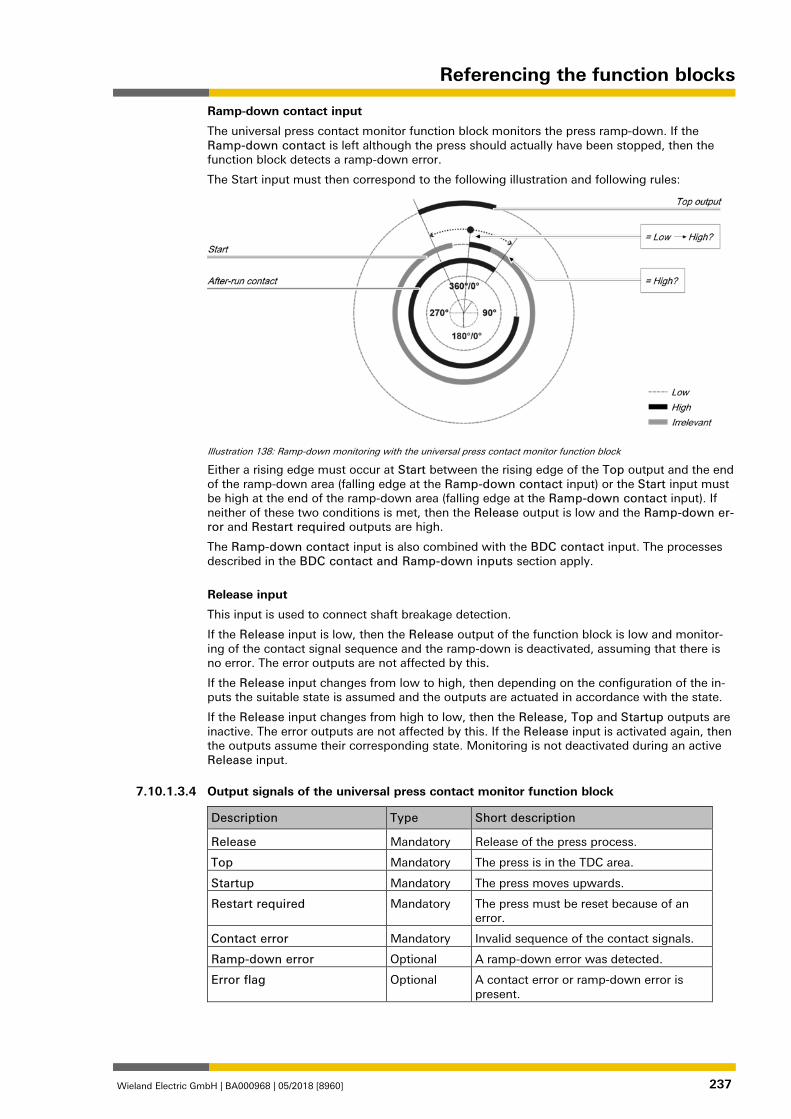
Referencing the function blocks
Wieland Electric GmbH | BA000968 | 05/2018 [8960] 237
Ramp-down contact input
The universal press contact monitor function block monitors the press ramp-down. If the Ramp-down contact is left although the press should actually have been stopped, then the function block detects a ramp-down error.
The Start input must then correspond to the following illustration and following rules:
Illustration 138: Ramp-down monitoring with the universal press contact monitor function block
Either a rising edge must occur at Start between the rising edge of the Top output and the end of the ramp-down area (falling edge at the Ramp-down contact input) or the Start input must be high at the end of the ramp-down area (falling edge at the Ramp-down contact input). If neither of these two conditions is met, then the Release output is low and the Ramp-down er-ror and Restart required outputs are high.
The Ramp-down contact input is also combined with the BDC contact input. The processes described in the BDC contact and Ramp-down inputs section apply.
Release input
This input is used to connect shaft breakage detection.
If the Release input is low, then the Release output of the function block is low and monitor-ing of the contact signal sequence and the ramp-down is deactivated, assuming that there is no error. The error outputs are not affected by this.
If the Release input changes from low to high, then depending on the configuration of the in-puts the suitable state is assumed and the outputs are actuated in accordance with the state.
If the Release input changes from high to low, then the Release, Top and Startup outputs are inactive. The error outputs are not affected by this. If the Release input is activated again, then the outputs assume their corresponding state. Monitoring is not deactivated during an active Release input. 1076767115
Output signals of the universal press contact monitor function block
Description Type Short description
Release Mandatory Release of the press process.
Top Mandatory The press is in the TDC area.
Startup Mandatory The press moves upwards.
Restart required Mandatory The press must be reset because of an error.
Contact error Mandatory Invalid sequence of the contact signals.
Ramp-down error Optional A ramp-down error was detected.
Error flag Optional A contact error or ramp-down error is present.
7.10.1.3.4
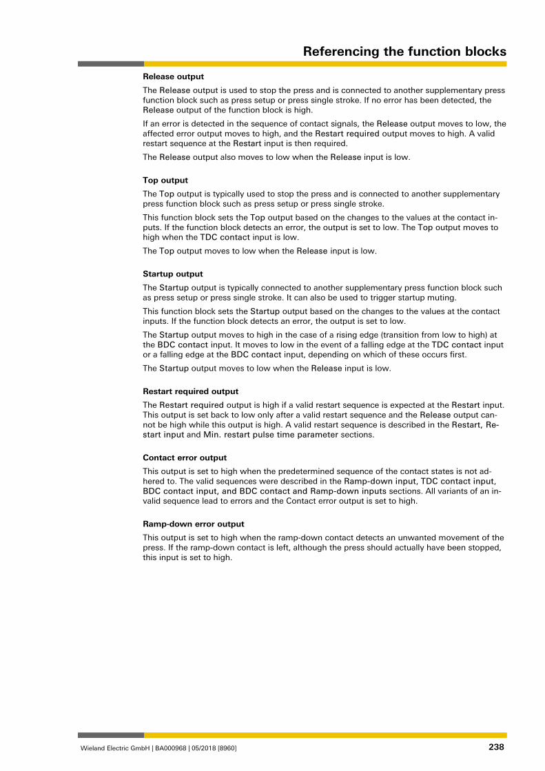
Referencing the function blocks
Wieland Electric GmbH | BA000968 | 05/2018 [8960] 238
Release output
The Release output is used to stop the press and is connected to another supplementary press function block such as press setup or press single stroke. If no error has been detected, the Release output of the function block is high.
If an error is detected in the sequence of contact signals, the Release output moves to low, the affected error output moves to high, and the Restart required output moves to high. A valid restart sequence at the Restart input is then required.
The Release output also moves to low when the Release input is low.
Top output
The Top output is typically used to stop the press and is connected to another supplementary press function block such as press setup or press single stroke.
This function block sets the Top output based on the changes to the values at the contact in-puts. If the function block detects an error, the output is set to low. The Top output moves to high when the TDC contact input is low.
The Top output moves to low when the Release input is low.
Startup output
The Startup output is typically connected to another supplementary press function block such as press setup or press single stroke. It can also be used to trigger startup muting.
This function block sets the Startup output based on the changes to the values at the contact inputs. If the function block detects an error, the output is set to low.
The Startup output moves to high in the case of a rising edge (transition from low to high) at the BDC contact input. It moves to low in the event of a falling edge at the TDC contact input or a falling edge at the BDC contact input, depending on which of these occurs first.
The Startup output moves to low when the Release input is low.
Restart required output
The Restart required output is high if a valid restart sequence is expected at the Restart input. This output is set back to low only after a valid restart sequence and the Release output can-not be high while this output is high. A valid restart sequence is described in the Restart, Re-start input and Min. restart pulse time parameter sections.
Contact error output
This output is set to high when the predetermined sequence of the contact states is not ad-hered to. The valid sequences were described in the Ramp-down input, TDC contact input, BDC contact input, and BDC contact and Ramp-down inputs sections. All variants of an in-valid sequence lead to errors and the Contact error output is set to high.
Ramp-down error output
This output is set to high when the ramp-down contact detects an unwanted movement of the press. If the ramp-down contact is left, although the press should actually have been stopped, this input is set to high.
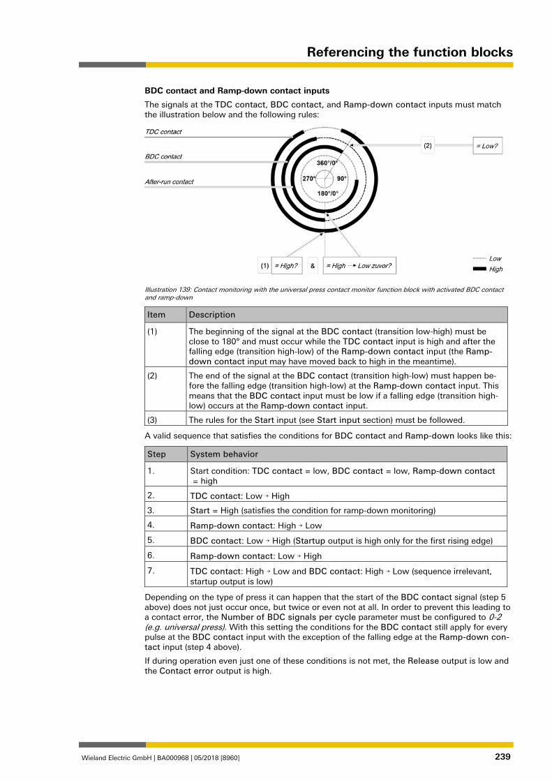
Referencing the function blocks
Wieland Electric GmbH | BA000968 | 05/2018 [8960] 239
BDC contact and Ramp-down contact inputs
The signals at the TDC contact, BDC contact, and Ramp-down contact inputs must match the illustration below and the following rules:
Illustration 139: Contact monitoring with the universal press contact monitor function block with activated BDC contact and ramp-down
Item Description
(1) The beginning of the signal at the BDC contact (transition low-high) must be close to 180° and must occur while the TDC contact input is high and after the falling edge (transition high-low) of the Ramp-down contact input (the Ramp-down contact input may have moved back to high in the meantime).
(2) The end of the signal at the BDC contact (transition high-low) must happen be-fore the falling edge (transition high-low) at the Ramp-down contact input. This means that the BDC contact input must be low if a falling edge (transition high-low) occurs at the Ramp-down contact input.
(3) The rules for the Start input (see Start input section) must be followed.
A valid sequence that satisfies the conditions for BDC contact and Ramp-down looks like this:
Step System behavior
1. Start condition: TDC contact = low, BDC contact = low, Ramp-down contact = high
2. TDC contact: Low → High
3. Start = High (satisfies the condition for ramp-down monitoring)
4. Ramp-down contact: High → Low
5. BDC contact: Low → High (Startup output is high only for the first rising edge)
6. Ramp-down contact: Low → High
7. TDC contact: High → Low and BDC contact: High → Low (sequence irrelevant, startup output is low)
Depending on the type of press it can happen that the start of the BDC contact signal (step 5 above) does not just occur once, but twice or even not at all. In order to prevent this leading to a contact error, the Number of BDC signals per cycle parameter must be configured to 0-2 (e.g. universal press). With this setting the conditions for the BDC contact still apply for every pulse at the BDC contact input with the exception of the falling edge at the Ramp-down con-tact input (step 4 above).
If during operation even just one of these conditions is not met, the Release output is low and the Contact error output is high.
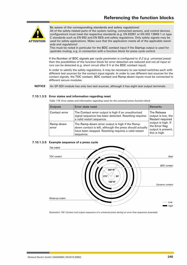
Referencing the function blocks
Wieland Electric GmbH | BA000968 | 05/2018 [8960] 240
ATTENTION
Be aware of the corresponding standards and safety regulations! All of the safety-related parts of the system (wiring, connected sensors, and control devices, configuration) must meet the respective standards (e.g. EN 62061 or EN ISO 13849-1 or type C standards such as EN 692 and EN 693) and safety regulations. Only safety signals may be used for safety applications. Make sure that the application meets all of the applicable stand-ards and regulations! This must be noted in particular for the BDC contact input if the Startup output is used for upstroke muting, e.g. in connection with a function block for press cycle control.
If the Number of BDC signals per cycle parameter is configured to 0-2 (e.g. universal press) then the possibilities of the function block for error detection are reduced and not all input er-rors can be detected (e.g. short circuit after 0 V at the BDC contact input).
In order to satisfy the safety regulations, it may be necessary to use tested switches each with different test sources for the contact input signals. In order to use different test sources for the contact signals, the TDC contact, BDC contact and Ramp-down inputs must be connected to different secure modules.
NOTICE An SP-SDI module has only two test sources, although it has eight test output terminals.
1076769803
Error states and information regarding reset Table 118: Error states and information regarding reset for the universal press function block
Outputs Error state reset Remarks
Contact error The Contact error output is high if an unauthorized signal sequence has been detected. Resetting requires a valid restart sequence.
The Release output is low, the Restart required output is high. If the Error flag output is present, this is high.
Ramp-down error
The Ramp-down error output is high if the Ramp-down contact is left, although the press should actually have been stopped. Resetting requires a valid restart sequence.
1119778443
Example sequence of a press cycle
Illustration 140: Contact and output sequence of a universal press during an error-free sequence (example)
7.10.1.3.5
7.10.1.3.6
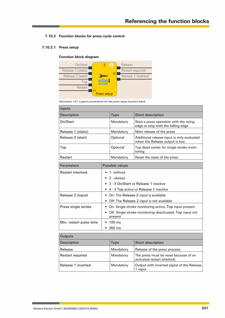
Referencing the function blocks
Wieland Electric GmbH | BA000968 | 05/2018 [8960] 241
Function blocks for press cycle control 1076796427
1076797963
Press setup
Function block diagram
Illustration 141: Logical connections for the press setup function block
Inputs
Description Type Short description
On/Start Mandatory Start a press operation with the rising edge or stop with the falling edge
Release 1 (static) Mandatory Main release of the press
Release 2 (start) Optional Additional release input is only evaluated when the Release output is low.
Top Optional Top dead center for single stroke moni-toring
Restart Mandatory Reset the state of the press
Parameters Possible values
Restart interlock • 1- without
• 2 - always
• 3 - if On/Start or Release 1 inactive
• 4 - if Top active or Release 1 inactive
Release 2 (input) • On: The Release 2 input is available
• Off: The Release 2 input is not available
Press single stroke • On: Single stroke monitoring active, Top input present
• Off: Single stroke monitoring deactivated, Top input not present
Min. restart pulse time • 100 ms
• 350 ms
Outputs
Description Type Short description
Release Mandatory Release of the press process.
Restart required Mandatory The press must be reset because of an activated restart interlock.
Release 1 inverted Mandatory Output with inverted signal of the Release 1 input.
1076864651
7.10.2
7.10.2.1
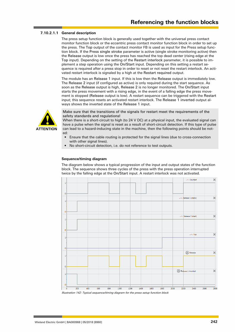
Referencing the function blocks
Wieland Electric GmbH | BA000968 | 05/2018 [8960] 242
General description
The press setup function block is generally used together with the universal press contact monitor function block or the eccentric press contact monitor function block in order to set up the press. The Top output of the contact monitor FB is used as input for the Press setup func-tion block. If the Press single stroke parameter is active (single stroke monitoring active) then the Release output is low once the press has reached the top dead center (rising edge at the Top input). Depending on the setting of the Restart interlock parameter, it is possible to im-plement a step operation using the On/Start input. Depending on this setting a restart se-quence is required after a press stop in order to reset or not reset the restart interlock. An acti-vated restart interlock is signaled by a high at the Restart required output.
The module has an Release 1 input. If this is low then the Release output is immediately low. The Release 2 input (if configured as active) is only required during the start sequence. As soon as the Release output is high, Release 2 is no longer monitored. The On/Start input starts the press movement with a rising edge, in the event of a falling edge the press move-ment is stopped (Release output is low). A restart sequence can be triggered with the Restart input; this sequence resets an activated restart interlock. The Release 1 inverted output al-ways shows the inverted state of the Release 1 input.
ATTENTION
Make sure that the transitions of the signals for restart meet the requirements of the safety standards and regulations! When there is a short-circuit to high (to 24 V DC) at a physical input, the evaluated signal can have a pulse when the signal is reset as a result of short-circuit detection. If this type of pulse can lead to a hazard-inducing state in the machine, then the following points should be not-ed: • Ensure that the cable routing is protected for the signal lines (due to cross-connection
with other signal lines). • No short-circuit detection, i.e. do not reference to test outputs.
Sequence/timing diagram
The diagram below shows a typical progression of the input and output states of the function block. The sequence shows three cycles of the press with the press operation interrupted twice by the falling edge at the On/Start input. A restart interlock was not activated.
Illustration 142: Typical sequence/timing diagram for the press setup function block
1076867339
7.10.2.1.1
Referencing the function blocks
Wieland Electric GmbH | BA000968 | 05/2018 [8960] 243
Parameters of the function block Table 119: Parameters of the press setup function block
Parameters Possible values
Restart interlock • 1- without
• 2 - always
• 3 - if On/Start or Release 1 inactive
• 4 - if Top active or Release 1 inactive
Release 2 (input) • On: The Release 2 input is available
• Off: The Release 2 input is not available
Press single stroke • On: Single stroke monitoring active, Top input present
• Off: Single stroke monitoring deactivated, Top input not present
Min. restart pulse time • 100 ms
• 350 ms
Restart interlock parameter
The Restart interlock parameter can be used to configure the behavior of the module after a stop. An activated restart interlock (triggered by a previous stop or a restart of the module) is signaled by a high signal at the Restart required output. The Restart required output only shows the activated restart interlock if the preconditions for a valid restart sequence are pre-sent. These are: Release 1 high and, if configured as active, also Release 2high.
In the case of configuration with 1 - without, no restart interlock is active (and the Restart re-quired output is not available) and the press operation can be advanced without a valid restart sequence. In other words in the event of interruption of the press operation by a rising edge at the Top input (with active single stroke monitoring) the press operation can be continued by a rising edge at the On/Start input. In the event of interruption of press operation by a falling edge at the On/Start input, the press operation can be continued by a rising edge at the On/Start input.
In the case of configuration with 2 - always the restart interlock is always active, i.e. the mod-ule starts with an activated restart interlock and each stop results in an active restart interlock that has to be reset by a valid restart sequence. Stops caused by a falling edge at On/Start, a rising edge of Top, or a falling edge of Release 1.
In the case of configuration with 3 - if On/Start or Release 1 inactive the restart interlock is active, i.e. the module starts with an activated restart interlock and every stop due to a falling edge at On/Start or a falling edge at Release 1 results in an active restart interlock that has to be reset through a valid restart sequence.
In the case of configuration with 4 - if Top active or Release 1 inactive, the restart interlock is active, i.e. the module starts with an activated restart interlock and every stop due to a rising edge at Top or a falling edge at Release 1 results in an active restart interlock that has to be reset by a valid restart sequence.
Release 2 parameter
This parameter activates the Release 2 input, if the parameter is active
Press single stroke parameter
This parameter activates the single stroke monitoring, if the parameter is active. This means the Top input is available and a rising edge at the Top input ends the press operation (i.e. a complete single stroke has been fully performed).
Min. restart pulse time parameter
A restart sequence (low-high-low Restart input) is only valid if the Restart input was set to high for at least 100 ms or 350 ms. This value is set with the Min. restart pulse time parame-ter. 1076868875
7.10.2.1.2
Referencing the function blocks
Wieland Electric GmbH | BA000968 | 05/2018 [8960] 244
Inputs of the press setup function block Table 120: Inputs of the press setup function block
Description Type Short description
On/Start Mandatory Start a press operation with the rising edge or stop with the falling edge
Release 1 (static) Mandatory Main release of the press
Release 2 (start) Optional Additional release input is only evaluated when the Release output is low.
Top Optional Top dead center for single stroke moni-toring
Restart Optional Reset the state of the press
The press setup function block supports the following input signals:
On/Start input
The On/Start input signal is used to indicate the beginning and end of the press movement. A rising edge (low to high) at the On/Start input signals a start of the press. A falling edge at the On/Start input (high to low) signals a stop of the press. If the Restart interlock parameter is set to 2 - always or 3 - if On/Start or Release 1 inactive then a valid Restart sequence is re-quired after a stop caused by a low at the On/Start input.
Release 1 (static) input
The Release 1 (static) input signal is mandatory. The Release output is always immediately low when Release 1 (static) is low.
If this function block is used together with a press contact function block (e.g. eccentric press contact monitor or universal press contact monitor), its Release output must be connected to the Release 1 (static) input of the press setup function block.
Release 2 (start)
The Release 2 (start) input signal is optional. If Release 2 (start) is configured, the Release output can only be high (e.g. during switch-on) if Release 2 (start) is high. If the Release out-put is high, Release 2 (start) is no longer monitored.
ATTENTION
Do not use the Release 2 (start) input for safety purposes! Do not use the Release 2 (start) input to initiate an emergency stop, because this input is only utilized temporarily during the start sequence. Otherwise you will place the press opera-tor in danger.
Top input
The Top input signal is optional. It is used to determine the end of the press cycle (i.e. the press has reached the top reversal point). This signal is available on the eccentric press contact monitor or universal press contact monitor function blocks. The Top input signal is used for single stroke monitoring. If the single stroke monitoring configuration parameter is set to ac-tive, the Release output is low if the Top input changes from low to high.
ATTENTION
Do not use the Top input for safety purposes! Only connect the Top input to a Top output of the universal press contact monitor or eccen-tric press contact monitor function blocks or to an equivalent signal source. Do not use the Top input to initiate an emergency stop. Otherwise you will place the press operator in dan-ger.
7.10.2.1.3
Referencing the function blocks
Wieland Electric GmbH | BA000968 | 05/2018 [8960] 245
Restart input
If the Restart interlock parameter is set to 1 - without, no restart signal is required to restart the press after a stop. The Restart interlock parameter can be set to the following values:
1 without
2 always
3 if On/Start or Release 1 inactive
4 if Top active or Release 1 inactive
This parameter determines when a Restart sequence is expected as input signal for the func-tion block.
If the Release output is low and, due to the aforementioned setting of the Restart interlock parameter a restart interlock is configured, the Release output can only be reset after a valid restart sequence has been completed with a low-high-low transition (minimum 100 ms or 350 ms; shorter pulses and pulses over 30 s are ignored). 1076870411
Outputs of the "Press setup” function block Table 121: Outputs of the press setup function block
Description Type Short description
Release Mandatory Release of the press process.
Restart required Optional The press must be reset because of an activated restart interlock.
Release 1 inverted Mandatory Output with inverted signal of the Release 1 input.
Release output
The Release output is high if Restart required is low (i.e. no restart is required) and the follow-ing conditions are satisfied:
If the Single stroke parameter is set to inactive, Release 1 (static) is high, and Release 2 (start) (if configured) is high; and a rising edge (low to high) is detected at the On/Start input. (In this case the Release output is low if the On/Start input changes from high to low or the Release 1 input is low); or
If the Single stroke parameter is set to active, Release 1 (static) is high and Release 2 (start) (if configured) is high; and a rising edge (low to high) is detected at the On/Start input. (In this case the Release output is low if the Top input changes from low to high or the On/Start input changes from high to low or the Release1 input is low)
Restart required output
The Restart required output is high if a valid restart sequence is expected at the Restart input. This output is set back to low only after a valid restart sequence and the Release output can-not be high while this output is high. A valid restart sequence is described in the Restart inter-lock parameter, Min. restart pulse time parameter and Restart input sections.
Release 1 inverted output
The Release 1 inverted output indicates whether a release signal is pending at the press setup function block. If the Release 1 input is high, the Release 1 inverted output is low and vice versa.
7.10.2.1.4
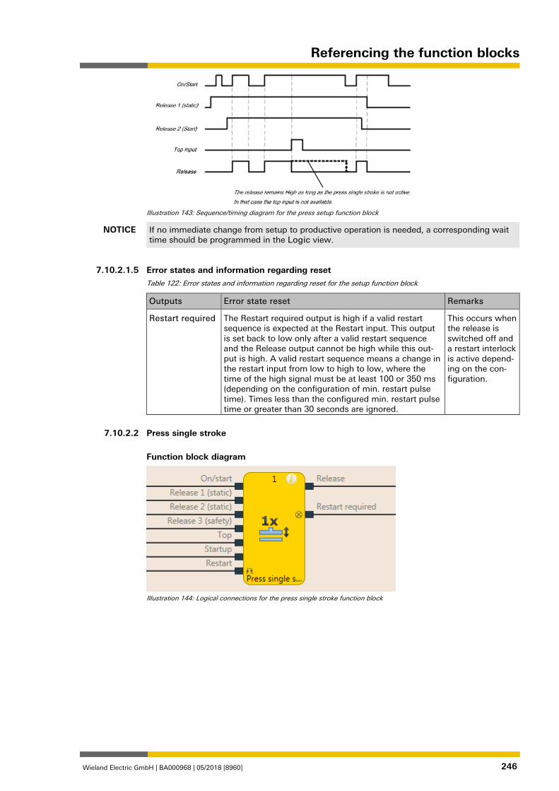
Referencing the function blocks
Wieland Electric GmbH | BA000968 | 05/2018 [8960] 246
Illustration 143: Sequence/timing diagram for the press setup function block
NOTICE If no immediate change from setup to productive operation is needed, a corresponding wait time should be programmed in the Logic view.
1076873099
Error states and information regarding reset Table 122: Error states and information regarding reset for the setup function block
Outputs Error state reset Remarks
Restart required The Restart required output is high if a valid restart sequence is expected at the Restart input. This output is set back to low only after a valid restart sequence and the Release output cannot be high while this out-put is high. A valid restart sequence means a change in the restart input from low to high to low, where the time of the high signal must be at least 100 or 350 ms (depending on the configuration of min. restart pulse time). Times less than the configured min. restart pulse time or greater than 30 seconds are ignored.
This occurs when the release is switched off and a restart interlock is active depend-ing on the con-figuration.
1076874635
Press single stroke
Function block diagram
Illustration 144: Logical connections for the press single stroke function block
7.10.2.1.5
7.10.2.2
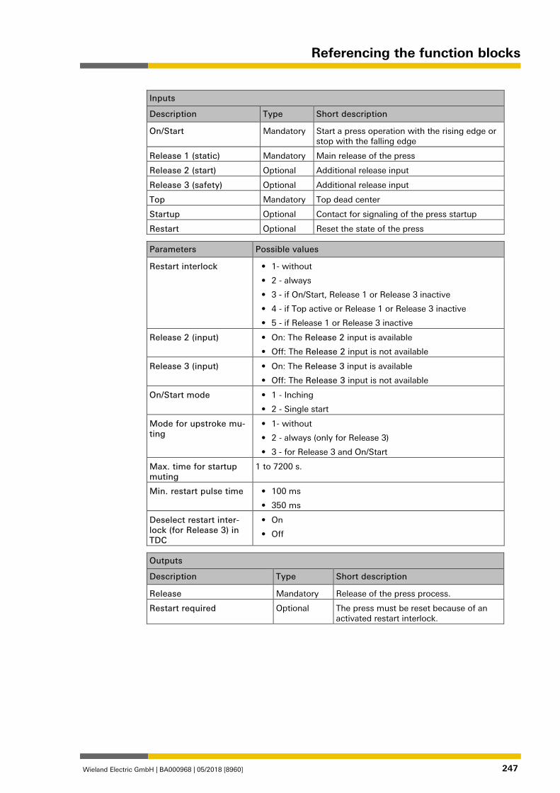
Referencing the function blocks
Wieland Electric GmbH | BA000968 | 05/2018 [8960] 247
Inputs
Description Type Short description
On/Start Mandatory Start a press operation with the rising edge or stop with the falling edge
Release 1 (static) Mandatory Main release of the press
Release 2 (start) Optional Additional release input
Release 3 (safety) Optional Additional release input
Top Mandatory Top dead center
Startup Optional Contact for signaling of the press startup
Restart Optional Reset the state of the press
Parameters Possible values
Restart interlock • 1- without
• 2 - always
• 3 - if On/Start, Release 1 or Release 3 inactive
• 4 - if Top active or Release 1 or Release 3 inactive
• 5 - if Release 1 or Release 3 inactive
Release 2 (input) • On: The Release 2 input is available
• Off: The Release 2 input is not available
Release 3 (input) • On: The Release 3 input is available
• Off: The Release 3 input is not available
On/Start mode • 1 - Inching
• 2 - Single start
Mode for upstroke mu-ting
• 1- without
• 2 - always (only for Release 3)
• 3 - for Release 3 and On/Start
Max. time for startup muting
1 to 7200 s.
Min. restart pulse time • 100 ms
• 350 ms
Deselect restart inter-lock (for Release 3) in TDC
• On
• Off
Outputs
Description Type Short description
Release Mandatory Release of the press process.
Restart required Optional The press must be reset because of an activated restart interlock.
1076877323
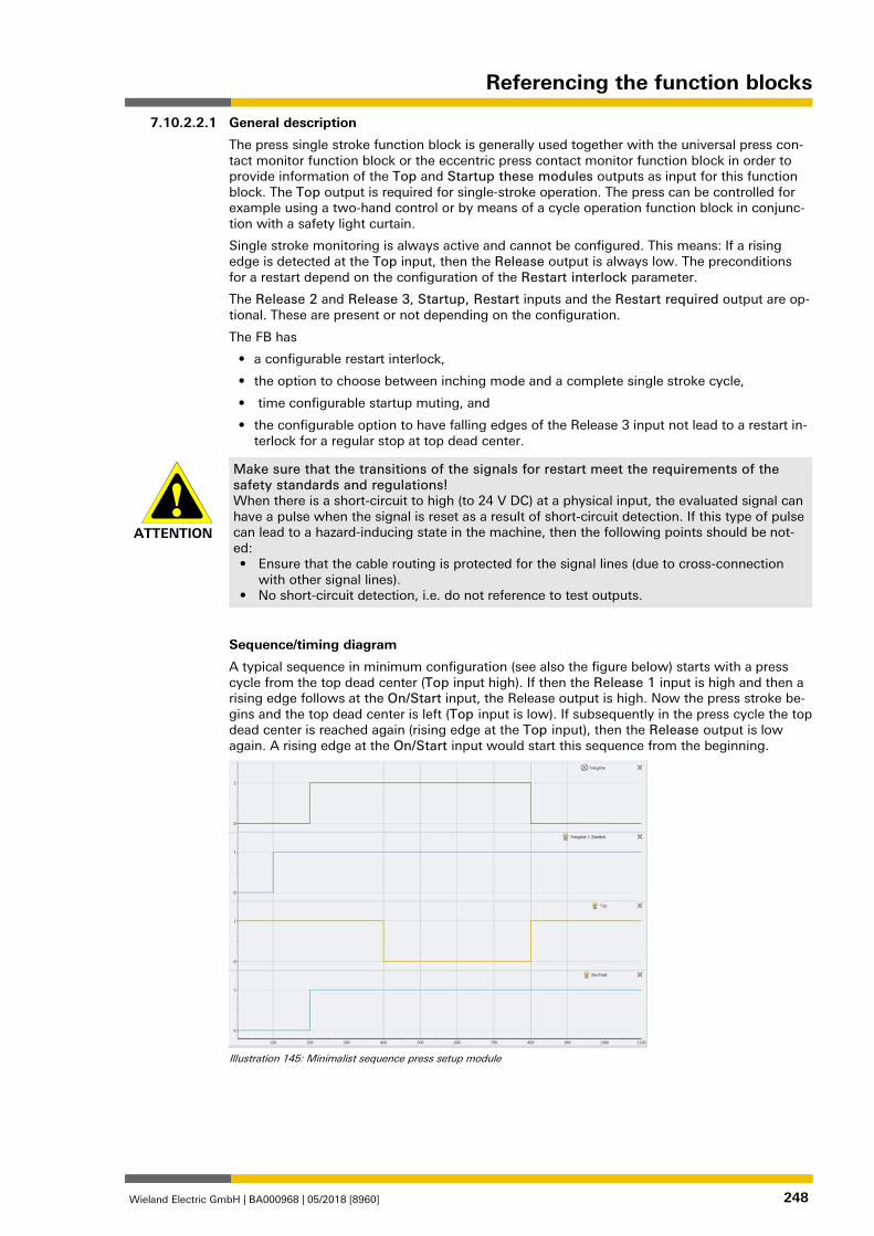
Referencing the function blocks
Wieland Electric GmbH | BA000968 | 05/2018 [8960] 248
General description
The press single stroke function block is generally used together with the universal press con-tact monitor function block or the eccentric press contact monitor function block in order to provide information of the Top and Startup these modules outputs as input for this function block. The Top output is required for single-stroke operation. The press can be controlled for example using a two-hand control or by means of a cycle operation function block in conjunc-tion with a safety light curtain.
Single stroke monitoring is always active and cannot be configured. This means: If a rising edge is detected at the Top input, then the Release output is always low. The preconditions for a restart depend on the configuration of the Restart interlock parameter.
The Release 2 and Release 3, Startup, Restart inputs and the Restart required output are op-tional. These are present or not depending on the configuration.
The FB has
• a configurable restart interlock,
• the option to choose between inching mode and a complete single stroke cycle,
• time configurable startup muting, and
• the configurable option to have falling edges of the Release 3 input not lead to a restart in-terlock for a regular stop at top dead center.
ATTENTION
Make sure that the transitions of the signals for restart meet the requirements of the safety standards and regulations! When there is a short-circuit to high (to 24 V DC) at a physical input, the evaluated signal can have a pulse when the signal is reset as a result of short-circuit detection. If this type of pulse can lead to a hazard-inducing state in the machine, then the following points should be not-ed: • Ensure that the cable routing is protected for the signal lines (due to cross-connection
with other signal lines). • No short-circuit detection, i.e. do not reference to test outputs.
Sequence/timing diagram
A typical sequence in minimum configuration (see also the figure below) starts with a press cycle from the top dead center (Top input high). If then the Release 1 input is high and then a rising edge follows at the On/Start input, the Release output is high. Now the press stroke be-gins and the top dead center is left (Top input is low). If subsequently in the press cycle the top dead center is reached again (rising edge at the Top input), then the Release output is low again. A rising edge at the On/Start input would start this sequence from the beginning.
Illustration 145: Minimalist sequence press setup module
1076878859
7.10.2.2.1
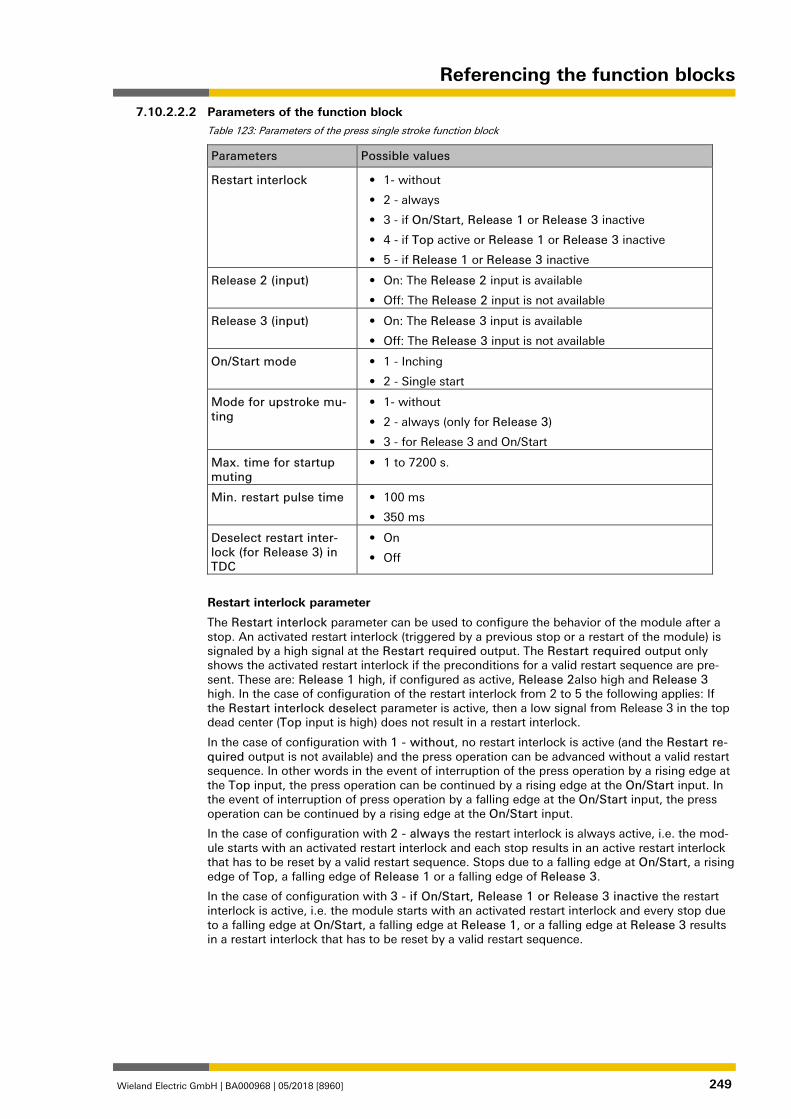
Referencing the function blocks
Wieland Electric GmbH | BA000968 | 05/2018 [8960] 249
Parameters of the function block Table 123: Parameters of the press single stroke function block
Parameters Possible values
Restart interlock • 1- without
• 2 - always
• 3 - if On/Start, Release 1 or Release 3 inactive
• 4 - if Top active or Release 1 or Release 3 inactive
• 5 - if Release 1 or Release 3 inactive
Release 2 (input) • On: The Release 2 input is available
• Off: The Release 2 input is not available
Release 3 (input) • On: The Release 3 input is available
• Off: The Release 3 input is not available
On/Start mode • 1 - Inching
• 2 - Single start
Mode for upstroke mu-ting
• 1- without
• 2 - always (only for Release 3)
• 3 - for Release 3 and On/Start
Max. time for startup muting
• 1 to 7200 s.
Min. restart pulse time • 100 ms
• 350 ms
Deselect restart inter-lock (for Release 3) in TDC
• On
• Off
Restart interlock parameter
The Restart interlock parameter can be used to configure the behavior of the module after a stop. An activated restart interlock (triggered by a previous stop or a restart of the module) is signaled by a high signal at the Restart required output. The Restart required output only shows the activated restart interlock if the preconditions for a valid restart sequence are pre-sent. These are: Release 1 high, if configured as active, Release 2also high and Release 3 high. In the case of configuration of the restart interlock from 2 to 5 the following applies: If the Restart interlock deselect parameter is active, then a low signal from Release 3 in the top dead center (Top input is high) does not result in a restart interlock.
In the case of configuration with 1 - without, no restart interlock is active (and the Restart re-quired output is not available) and the press operation can be advanced without a valid restart sequence. In other words in the event of interruption of the press operation by a rising edge at the Top input, the press operation can be continued by a rising edge at the On/Start input. In the event of interruption of press operation by a falling edge at the On/Start input, the press operation can be continued by a rising edge at the On/Start input.
In the case of configuration with 2 - always the restart interlock is always active, i.e. the mod-ule starts with an activated restart interlock and each stop results in an active restart interlock that has to be reset by a valid restart sequence. Stops due to a falling edge at On/Start, a rising edge of Top, a falling edge of Release 1 or a falling edge of Release 3.
In the case of configuration with 3 - if On/Start, Release 1 or Release 3 inactive the restart interlock is active, i.e. the module starts with an activated restart interlock and every stop due to a falling edge at On/Start, a falling edge at Release 1, or a falling edge at Release 3 results in a restart interlock that has to be reset by a valid restart sequence.
7.10.2.2.2
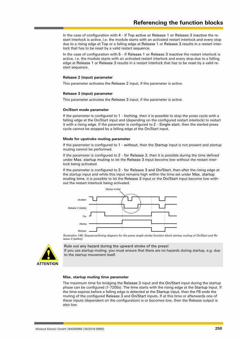
Referencing the function blocks
Wieland Electric GmbH | BA000968 | 05/2018 [8960] 250
In the case of configuration with 4 - if Top active or Release 1 or Release 3 inactive the re-start interlock is active, i.e. the module starts with an activated restart interlock and every stop due to a rising edge at Top or a falling edge at Release 1 or Release 3 results in a restart inter-lock that has to be reset by a valid restart sequence.
In the case of configuration with 5 - if Release 1 or Release 3 inactive the restart interlock is active, i.e. the module starts with an activated restart interlock and every stop due to a falling edge at Release 1 or Release 3 results in a restart interlock that has to be reset by a valid re-start sequence.
Release 2 (input) parameter
This parameter activates the Release 2 input, if the parameter is active.
Release 3 (input) parameter
This parameter activates the Release 3 input, if the parameter is active.
On/Start mode parameter
If the parameter is configured to 1 - Inching, then it is possible to stop the press cycle with a falling edge at the On/Start input and (depending on the configured restart interlock) to restart it with a rising edge. If the parameter is configured to 2 - Single start, then the started press cycle cannot be stopped by a falling edge at the On/Start input.
Mode for upstroke muting parameter
If the parameter is configured to 1 - without, then the Startup input is not present and startup muting cannot be performed.
If the parameter is configured to 2 - for Release 3, then it is possible during the time defined under Max. startup muting to let the Release 3 input become low without the restart inter-lock being activated.
If the parameter is configured to 3 - for Release 3 and On/Start, then after the rising edge at the startup input and while this input remains high within the time set under Max. startup muting time, it is possible to let the Release 3 input or the On/Start input become low with-out the restart interlock being activated.
Illustration 146: Sequence/timing diagram for the press single stroke function block startup muting of On/Start and Re-lease 3 (safety)
ATTENTION
Rule out any hazard during the upward stroke of the press! If you use startup muting, you must ensure that there are no hazards during startup, e.g. due to the startup movement itself.
Max. startup muting time parameter
The maximum time for bridging the Release 3 input and the On/Start input during the startup phase can be configured (1-7200s). The time starts with the rising edge at the Startup input. If the time expires before a falling edge is detected at the Startup input, then the FB ends the muting of the configured Release 3 and On/Start inputs. If at this time or afterwards one of these inputs (dependent on the configuration) is or becomes low, then the Release output is also low.
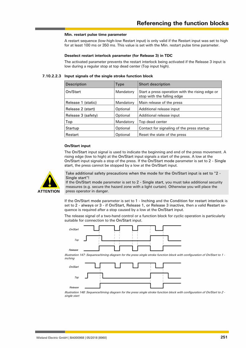
Referencing the function blocks
Wieland Electric GmbH | BA000968 | 05/2018 [8960] 251
Min. restart pulse time parameter
A restart sequence (low-high-low Restart input) is only valid if the Restart input was set to high for at least 100 ms or 350 ms. This value is set with the Min. restart pulse time parameter.
Deselect restart interlock parameter (for Release 3) in TDC
The activated parameter prevents the restart interlock being activated if the Release 3 input is low during a regular stop at top dead center (Top input high). 1076883211
Input signals of the single stroke function block
Description Type Short description
On/Start Mandatory Start a press operation with the rising edge or stop with the falling edge
Release 1 (static) Mandatory Main release of the press
Release 2 (start) Optional Additional release input
Release 3 (safety) Optional Additional release input
Top Mandatory Top dead center
Startup Optional Contact for signaling of the press startup
Restart Optional Reset the state of the press
On/Start input
The On/Start input signal is used to indicate the beginning and end of the press movement. A rising edge (low to high) at the On/Start input signals a start of the press. A low at the On/Start input signals a stop of the press. If the On/Start mode parameter is set to 2 - Single start, the press cannot be stopped by a low at the On/Start input.
ATTENTION
Take additional safety precautions when the mode for the On/Start input is set to "2 - Single start"! If the On/Start mode parameter is set to 2 - Single start, you must take additional security measures (e.g. secure the hazard zone with a light curtain). Otherwise you will place the press operator in danger.
If the On/Start mode parameter is set to 1 - Inching and the Condition for restart interlock is set to 2 - always or 3 - if On/Start, Release 1, or Release 3 inactive, then a valid Restart se-quence is required after a stop caused by a low at the On/Start input.
The release signal of a two-hand control or a function block for cyclic operation is particularly suitable for connection to the On/Start input.
Illustration 147: Sequence/timing diagram for the press single stroke function block with configuration of On/Start to 1 - inching
Illustration 148: Sequence/timing diagram for the press single stroke function block with configuration of On/Start to 2 - single start
7.10.2.2.3
Referencing the function blocks
Wieland Electric GmbH | BA000968 | 05/2018 [8960] 252
Release 1 (static) input
The Release 1 (static) input signal is mandatory. The Release output is always immediately low when Release 1 (static) is low.
If this function block is used together with a press contact function block (e.g. eccentric press contact monitor or universal press contact monitor), its release signal must be connected to the Release 1 (static) input of this function block.
Release 2 (start) input
The Release 2 (start) input signal is optional. If Release 2 (start) is configured, the Release output can only be high (e.g. during switch-on) if Release 2 (start) is high. If the Release out-put is high, Release 2 (start) is no longer monitored.
ATTENTION
Do not use the Release 2 (start) input for safety purposes! Do not use the Release 2 (start) input to initiate an emergency stop, because this input is only utilized temporarily during the start sequence. Otherwise you will place the press opera-tor in danger.
Release 3 (safety) input
The Release 3 (safety) input signal is an optional signal. If Release 3 (safety) is configured, the Release output can only be high if Release 3 (safety) is high. If Release 3 (safety) is low and Startup muting is not active, then the Release output is set to low and a Restart se-quence must be done in accordance with the configuration.
If Release 1 (static) and Startup are high and the configured startup time has not yet expired, then the Release 3 (safety) signal is bypassed (startup muting).
Top input
The Top input signal is used to determine the end of the press cycle (i.e. the press has reached the top dead center). This signal is available at the eccentric press contact monitor and univer-sal press contact monitor function blocks. The Top input signal is used for single stroke moni-toring. The Release output is low if the Top input passes from low to high.
ATTENTION
Do not use the Top input for safety purposes! Only connect the Top input to a Top output of the universal press contact monitor or eccen-tric press contact monitor function blocks or to an equivalent signal source. Do not use the Top input to initiate an emergency stop. Otherwise you will place the press operator in dan-ger.
Startup input
If the Startup input is present because of the configuration, then this must be connected.
NOTICE Only connect the Startup input to the Startup output of an eccentric press contact monitor or universal press contact monitor function block.
If the input is available, then the Release 3 (safety) and On/Start input signals are bypassed (muting of the On/Start input depends on the parameter settings) if the Release output is high and the Startup input is high. This function block does not perform a plausibility check of the Startup input signal. If the Startup input is high several times during a single press cycle, then it is possible to bypass the corresponding input of the function block several times. If a signal should not be bypassed, then together with other signals that must be connected to the Re-lease 1 (static) input it should be connected to the Release 1 (static) input by means of an AND function block.
ATTENTION
Rule out any hazard during the startup of the press! If you use startup muting, you must ensure that there are no hazards during startup, e.g. due to the startup movement itself.
Referencing the function blocks
Wieland Electric GmbH | BA000968 | 05/2018 [8960] 253
Restart input
If the Restart interlock parameter has been set to 1 - without, no restart signal is required to restart the press after a stop. The Restart interlock parameter can be set to the following val-ues:
• 1- without
• 2 - always
• 3 - if On/Start, Release 1 or Release 3 inactive
• 4 - if Top active or Release 1 or Release 3 inactive
• 5 - if Release 1 or Release 3 inactive
This parameter determines when a valid restart sequence is expected as input signal for the function block.
If the Release output is low, the Release output can only be reset in the case of settings 2 to 5 after a valid Restart sequence has been completed at the Restart input with a low-high-low transition (minimum 100 ms or 350 ms; shorter pulses and pulses over 30 s are ignored). 1076887563
Output signals of the function block
Description Type Short description
Release Mandatory Release of the press process.
Restart required Optional The press must be reset because of an activated restart interlock.
Release output
The Release output is high if Restart required is low (i.e. no restart is required) and the follow-ing conditions are satisfied:
• The Release 1 input is high;
• if activated, Release 2 must also be high;
• if activated, Release 3 must also be high;
• and a rising edge at the On/Start input is detected;
Restart required output
The Restart required output is high if a valid Restart sequence is expected at the Restart in-put. 1076889099
Error states and information regarding reset Table 124: Error states and information regarding reset for the single stroke function block
Outputs Error state reset Remarks
Restart required The Restart required output is high if a valid restart sequence is expected at the Restart input. This output is set back to low only after a valid restart sequence and the Release output cannot be high while this out-put is high. A valid restart sequence means a change in the restart input from low to high to low where the time of the high signal must be at least 100 ms or 350 ms (depending on the configuration of min. restart pulse time). Times less than the configured min. restart pulse time or greater than 30 seconds are ignored.
This occurs when stopped depend-ing on the con-figuration of the restart interlock.
1076890635
7.10.2.2.4
7.10.2.2.5
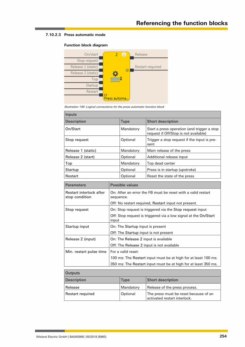
Referencing the function blocks
Wieland Electric GmbH | BA000968 | 05/2018 [8960] 254
Press automatic mode
Function block diagram
Illustration 149: Logical connections for the press automatic function block
Inputs
Description Type Short description
On/Start Mandatory Start a press operation (and trigger a stop request if Off/Stop is not available)
Stop request Optional Trigger a stop request if the input is pre-sent
Release 1 (static) Mandatory Main release of the press
Release 2 (start) Optional Additional release input
Top Mandatory Top dead center
Startup Optional Press is in startup (upstroke)
Restart Optional Reset the state of the press
Parameters Possible values
Restart interlock after stop condition
On: After an error the FB must be reset with a valid restart sequence.
Off: No restart required, Restart input not present.
Stop request On: Stop request is triggered via the Stop request input
Off: Stop request is triggered via a low signal at the On/Start input
Startup input On: The Startup input is present
Off: The Startup input is not present
Release 2 (input) On: The Release 2 input is available
Off: The Release 2 input is not available
Min. restart pulse time For a valid reset:
100 ms: The Restart input must be at high for at least 100 ms.
350 ms: The Restart input must be at high for at least 350 ms.
Outputs
Description Type Short description
Release Mandatory Release of the press process.
Restart required Optional The press must be reset because of an activated restart interlock.
1076893323
7.10.2.3
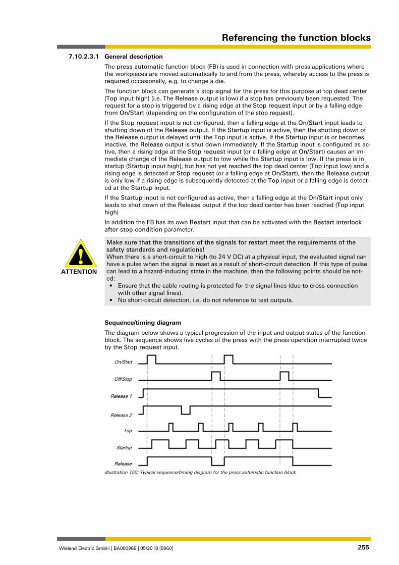
Referencing the function blocks
Wieland Electric GmbH | BA000968 | 05/2018 [8960] 255
General description
The press automatic function block (FB) is used in connection with press applications where the workpieces are moved automatically to and from the press, whereby access to the press is required occasionally, e.g. to change a die.
The function block can generate a stop signal for the press for this purpose at top dead center (Top input high) (i.e. The Release output is low) if a stop has previously been requested. The request for a stop is triggered by a rising edge at the Stop request input or by a falling edge from On/Start (depending on the configuration of the stop request).
If the Stop request input is not configured, then a falling edge at the On/Start input leads to shutting down of the Release output. If the Startup input is active, then the shutting down of the Release output is delayed until the Top input is active. If the Startup input is or becomes inactive, the Release output is shut down immediately. If the Startup input is configured as ac-tive, then a rising edge at the Stop request input (or a falling edge at On/Start) causes an im-mediate change of the Release output to low while the Startup input is low. If the press is in startup (Startup input high), but has not yet reached the top dead center (Top input low) and a rising edge is detected at Stop request (or a falling edge at On/Start), then the Release output is only low if a rising edge is subsequently detected at the Top input or a falling edge is detect-ed at the Startup input.
If the Startup input is not configured as active, then a falling edge at the On/Start input only leads to shut down of the Release output if the top dead center has been reached (Top input high)
In addition the FB has its own Restart input that can be activated with the Restart interlock after stop condition parameter.
ATTENTION
Make sure that the transitions of the signals for restart meet the requirements of the safety standards and regulations! When there is a short-circuit to high (to 24 V DC) at a physical input, the evaluated signal can have a pulse when the signal is reset as a result of short-circuit detection. If this type of pulse can lead to a hazard-inducing state in the machine, then the following points should be not-ed: • Ensure that the cable routing is protected for the signal lines (due to cross-connection
with other signal lines). • No short-circuit detection, i.e. do not reference to test outputs.
Sequence/timing diagram
The diagram below shows a typical progression of the input and output states of the function block. The sequence shows five cycles of the press with the press operation interrupted twice by the Stop request input.
Illustration 150: Typical sequence/timing diagram for the press automatic function block
1076896011
7.10.2.3.1
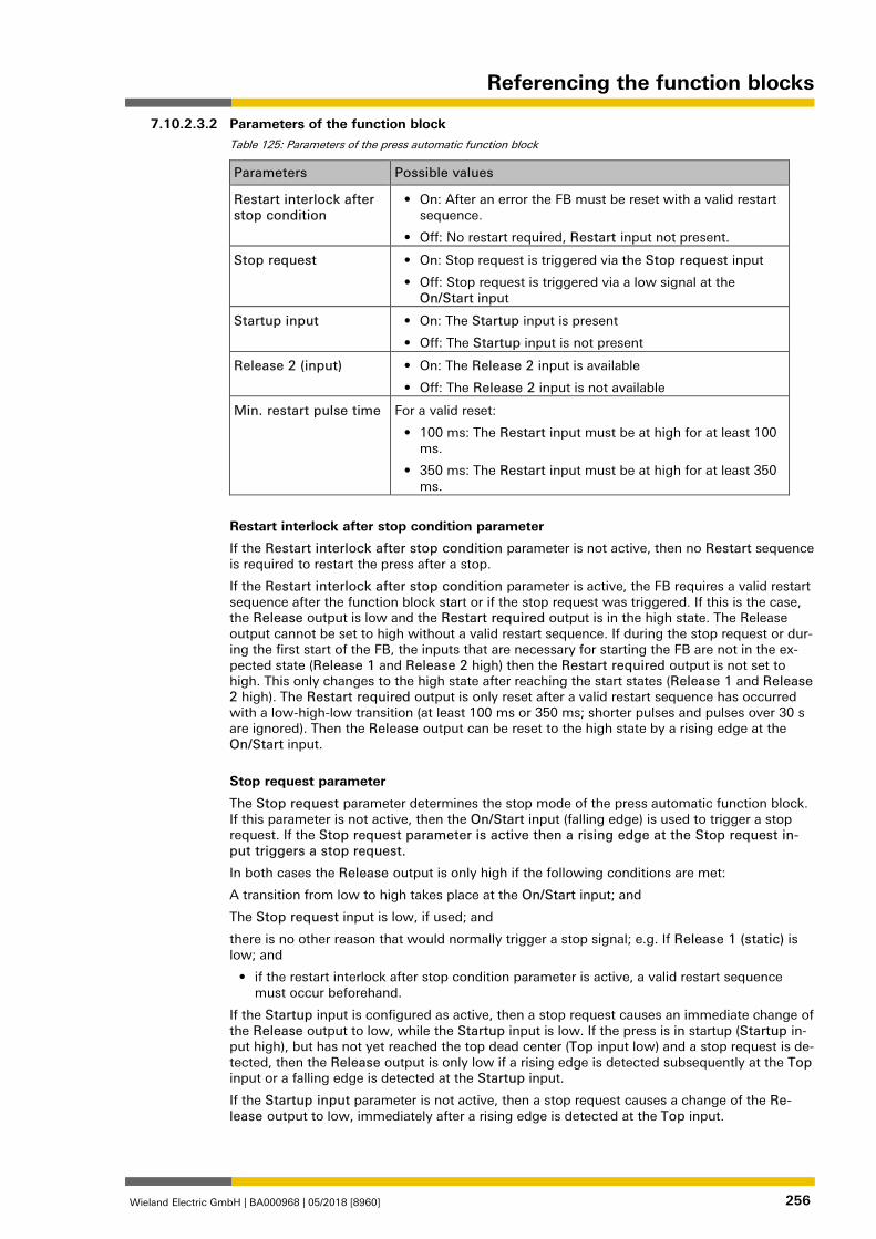
Referencing the function blocks
Wieland Electric GmbH | BA000968 | 05/2018 [8960] 256
Parameters of the function block Table 125: Parameters of the press automatic function block
Parameters Possible values
Restart interlock after stop condition
• On: After an error the FB must be reset with a valid restart sequence.
• Off: No restart required, Restart input not present.
Stop request • On: Stop request is triggered via the Stop request input
• Off: Stop request is triggered via a low signal at the On/Start input
Startup input • On: The Startup input is present
• Off: The Startup input is not present
Release 2 (input) • On: The Release 2 input is available
• Off: The Release 2 input is not available
Min. restart pulse time For a valid reset:
• 100 ms: The Restart input must be at high for at least 100 ms.
• 350 ms: The Restart input must be at high for at least 350 ms.
Restart interlock after stop condition parameter
If the Restart interlock after stop condition parameter is not active, then no Restart sequence is required to restart the press after a stop.
If the Restart interlock after stop condition parameter is active, the FB requires a valid restart sequence after the function block start or if the stop request was triggered. If this is the case, the Release output is low and the Restart required output is in the high state. The Release output cannot be set to high without a valid restart sequence. If during the stop request or dur-ing the first start of the FB, the inputs that are necessary for starting the FB are not in the ex-pected state (Release 1 and Release 2 high) then the Restart required output is not set to high. This only changes to the high state after reaching the start states (Release 1 and Release 2 high). The Restart required output is only reset after a valid restart sequence has occurred with a low-high-low transition (at least 100 ms or 350 ms; shorter pulses and pulses over 30 s are ignored). Then the Release output can be reset to the high state by a rising edge at the On/Start input.
Stop request parameter
The Stop request parameter determines the stop mode of the press automatic function block. If this parameter is not active, then the On/Start input (falling edge) is used to trigger a stop request. If the Stop request parameter is active then a rising edge at the Stop request in-put triggers a stop request.
In both cases the Release output is only high if the following conditions are met:
A transition from low to high takes place at the On/Start input; and
The Stop request input is low, if used; and
there is no other reason that would normally trigger a stop signal; e.g. If Release 1 (static) is low; and
• if the restart interlock after stop condition parameter is active, a valid restart sequence must occur beforehand.
If the Startup input is configured as active, then a stop request causes an immediate change of the Release output to low, while the Startup input is low. If the press is in startup (Startup in-put high), but has not yet reached the top dead center (Top input low) and a stop request is de-tected, then the Release output is only low if a rising edge is detected subsequently at the Top input or a falling edge is detected at the Startup input.
If the Startup input parameter is not active, then a stop request causes a change of the Re-lease output to low, immediately after a rising edge is detected at the Top input.
7.10.2.3.2
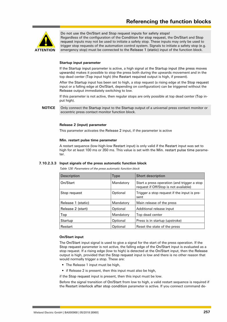
Referencing the function blocks
Wieland Electric GmbH | BA000968 | 05/2018 [8960] 257
ATTENTION
Do not use the On/Start and Stop request inputs for safety stops! Regardless of the configuration of the Condition for stop request, the On/Start and Stop request inputs may not be used to initiate a safety stop. These inputs may only be used to trigger stop requests of the automation control system. Signals to initiate a safety stop (e.g. emergency stop) must be connected to the Release 1 (static) input of the function block.
Startup input parameter
If the Startup input parameter is active, a high signal at the Startup input (the press moves upwards) makes it possible to stop the press both during the upwards movement and in the top dead center (Top input high) (the Restart required output is high, if present).
After the Startup input has been set to high, a stop request (a rising edge at the Stop request input or a falling edge at On/Start, depending on configuration) can be triggered without the Release output immediately switching to low.
If this parameter is not active, then regular stops are only possible at top dead center (Top in-put high).
NOTICE Only connect the Startup input to the Startup output of a universal press contact monitor or eccentric press contact monitor function block.
Release 2 (input) parameter
This parameter activates the Release 2 input, if the parameter is active
Min. restart pulse time parameter
A restart sequence (low-high-low Restart input) is only valid if the Restart input was set to high for at least 100 ms or 350 ms. This value is set with the Min. restart pulse time parame-ter. 1076897547
Input signals of the press automatic function block Table 126: Parameters of the press automatic function block
Description Type Short description
On/Start Mandatory Start a press operation (and trigger a stop request if Off/Stop is not available)
Stop request Optional Trigger a stop request if the input is pre-sent
Release 1 (static) Mandatory Main release of the press
Release 2 (start) Optional Additional release input
Top Mandatory Top dead center
Startup Optional Press is in startup (upstroke)
Restart Optional Reset the state of the press
On/Start input
The On/Start input signal is used to give a signal for the start of the press operation. If the Stop request parameter is not active, the falling edge of the On/Start input is evaluated as a stop request. If a rising edge (low to high) is detected at the On/Start input, then the Release output is high, provided that the Stop request input is low and there is no other reason that would normally trigger a stop. These are:
• The Release 1 input must be high,
• if Release 2 is present, then this input must also be high,
if the Stop request input is present, then this input must be low.
Before the signal transition of On/Start from low to high, a valid restart sequence is required if the Restart interlock after stop condition parameter is active. If you connect command de-
7.10.2.3.3
Referencing the function blocks
Wieland Electric GmbH | BA000968 | 05/2018 [8960] 258
vices (e.g. a two-hand controller) to the On/Start input, you must ensure that no unintended restart is possible.
Off/Stop input
If the Stop request parameter is active, then the Stop request input is used to signal a stop request (rising edge at Off/Stop) to the press. If the Startup input is configured as active, then a stop request causes an immediate change of the Release output to low, while the Startup input is low. If the press is in startup (Startup input high), but has not yet reached the top dead center (Top input low) and a stop request is detected, then the Release output is only low if a rising edge is detected subsequently at the Top input or a falling edge is detected at the Startup input. If the Release output is low then in this case the Restart required output is set to high if the Restart interlock after stop condition parameter is active.
If the Startup input parameter is not active, then a stop request causes a change of the Re-lease output to low, immediately after a rising edge is detected at the Top input.
This input can be used only if the Stop request parameter is active.
The Stop request input is intended for the connection of non-safety related signals (e.g. from a programmable logic controller (PLC)). Safety-related signals may only be connected to the Re-lease 1 (static) input, not to the Stop request input.
Release 1 (static) input
The Release 1 input signal is mandatory. The Release output is always immediately low when Release 1 is low.
If this function block is used together with a press contact function block (e.g. eccentric press contact monitor or universal press contact monitor), its Release output must be connected to the Release 1 input of this function block.
Release 2 (start) input
The Release 2 input is optional. If the Release 2 parameter is active, the Release output can only be high (e.g. during switch on) if the Release 2 input is high. As soon as the Release out-put is high, the Release 2 input is no longer monitored.
ATTENTION
Do not use the Release 2 (start) input for safety purposes! Do not use the Release 2 (start) input to initiate an emergency stop, because this input is only utilized temporarily during the start sequence. Otherwise you will place the press opera-tor in danger.
Top input
The Top input is used to determine the end of the press cycle (i.e. the press has reached the top dead center). If the Restart interlock after stop condition parameter is active and a stop request was present, then the Restart required output is high and the Release output low due to the rising edge of the Top input.
If the Restart interlock after stop condition parameter is not active and a stop request was present, then only the Release output is low due to the rising edge of the Top input. This sig-nal is available at the eccentric press contact monitor and universal press contact monitor function blocks.
ATTENTION
Do not use the Top input for safety purposes! Do not use the Top input to initiate an emergency stop. Otherwise you will place the press operator in danger.
Referencing the function blocks
Wieland Electric GmbH | BA000968 | 05/2018 [8960] 259
Startup input
The Startup input allows the press to stop both during the upwards movement and in the top dead center (Top input high). If the parameter is not active, then regular stops are only possible at top dead center.
NOTICE Do not use the Startup input for safety purposes! Only connect the Startup input to the Startup output of a universal press contact monitor or eccentric press contact monitor function block.
Restart input
If the Restart interlock after stop condition parameter is active, then the Restart input is pre-sent. In this case the Restart required output must be reset in the event of the first start of the module or after a successful stop (Release output is low). Reset is done by a valid restart se-quence. This means a change in the Restart input from low to high to low where the time of the high signal must be at least 100 ms or 350 ms (depending on the configuration of Min. re-start pulse time). Times less than the configured Min. restart pulse time or greater than 30 seconds are ignored. 1076899083
Outputs of the press automatic function block Table 127: Parameters of the press automatic function block
Description Type Short description
Release Mandatory Release of the press operation
Restart required Optional The press must be reset because of an error.
Release output
The press operation can only be performed is the Release output is high. The output is con-trolled depending on the parameters and input states of the function block. If the Release out-put is high, the Restart required output is always low. Both outputs can be low at the same time.
Restart required output
The Restart required output is high if a valid restart sequence is expected at the Restart input. This output is set back to low only after a valid restart sequence and the Release output can-not be high while this output is high. A valid restart sequence is described in the Restart inter-lock after stop condition parameter, Min. restart pulse time parameter, and Restart input sections. 1076900619
Error states and information regarding reset Table 128: Error states and information regarding reset for the automatic function block
Outputs Error state reset Remarks
Restart required The Restart required output is high if a valid restart sequence is expected at the Restart input. This output is set back to low only after a valid restart sequence and the Release output cannot be high while this out-put is high. A valid restart sequence means a change in the Restart required input from low to high to low where the time of the high signal must be at least 100 ms or 350 ms (depending on the configuration of min. restart pulse time). Times less than the configured min. restart pulse time or greater than 30 seconds are ig-nored.
This occurs when stopped depend-ing on the con-figuration of the restart interlock.
1076902155
7.10.2.3.4
7.10.2.3.5
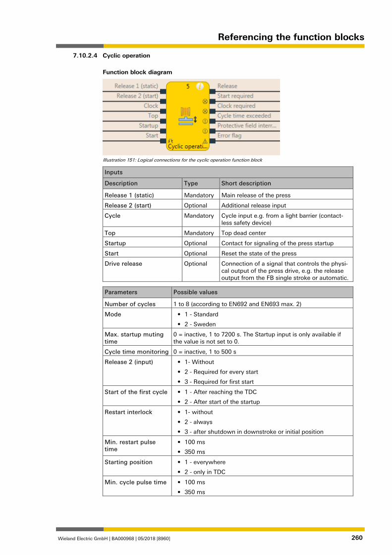
Referencing the function blocks
Wieland Electric GmbH | BA000968 | 05/2018 [8960] 260
Cyclic operation
Function block diagram
Illustration 151: Logical connections for the cyclic operation function block
Inputs
Description Type Short description
Release 1 (static) Mandatory Main release of the press
Release 2 (start) Optional Additional release input
Cycle Mandatory Cycle input e.g. from a light barrier (contact-less safety device)
Top Mandatory Top dead center
Startup Optional Contact for signaling of the press startup
Start Optional Reset the state of the press
Drive release Optional Connection of a signal that controls the physi-cal output of the press drive, e.g. the release output from the FB single stroke or automatic.
Parameters Possible values
Number of cycles 1 to 8 (according to EN692 and EN693 max. 2)
Mode • 1 - Standard
• 2 - Sweden
Max. startup muting time
0 = inactive, 1 to 7200 s. The Startup input is only available if the value is not set to 0.
Cycle time monitoring 0 = inactive, 1 to 500 s
Release 2 (input) • 1- Without
• 2 - Required for every start
• 3 - Required for first start
Start of the first cycle • 1 - After reaching the TDC
• 2 - After start of the startup
Restart interlock • 1- without
• 2 - always
• 3 - after shutdown in downstroke or initial position
Min. restart pulse time
• 100 ms
• 350 ms
Starting position • 1 - everywhere
• 2 - only in TDC
Min. cycle pulse time • 100 ms
• 350 ms
7.10.2.4
Referencing the function blocks
Wieland Electric GmbH | BA000968 | 05/2018 [8960] 261
Use error flag • On: The error flag output is present
• Off: The error flag output is not present
Outputs
Description Type Short description
Release Mandatory Release of the press process.
Start required Optional The press must be reset in the event of an activated restart interlock.
Cycle required Mandatory One (or several) intervention(s) is (are) required to continue the press cycle.
Cycle time exceeded Mandatory Exceeding the set cycle time monitoring is signaled.
Protective field intervention Mandatory Signals an unauthorized intervention.
Start not possible here Optional A stop outside of the top dead center has been performed. The press must first be moved back to top dead center.
Error flag Optional A cycle time exceeded or an unexpected cycle is present
1076904843
General description
The cyclic operation function block is used for press applications with cyclic operation (PSDI = Press Sensing Device Initiation).
ATTENTION
Ensure the safety rules for cyclic operation are satisfied! The requirements for cyclic operation (PSDI) are described in local, regional, national, and international standards. Always bring the cyclic operation applications in line with these standards and regulations as well as with your risk analysis and avoidance strategy. If the contactless safety device (e.g. safety light curtain) is not used in an operating mode, the contactless safety device must be switched off in this mode so that it is clear that the con-tactless safety device is not currently active in safety mode. If more than one contactless safety device (e.g. safety light curtain) is used in an application that uses the N-cycle functions (PSDI), then only one contactless safety device may be used to meet the requirements for the N-cyclic operation (PSDI). In accordance with EN 692 and EN 693 for press applications, the number of interventions is limited to 1 or 2. Other applications are subject to the applicable standards.
ATTENTION
Prevent access to dangerous movement! Press systems with a configuration that would allow a person to penetrate the safety zone of a contactless safety device, cross it and leave it, are not permitted for cyclic operation.
This function block defines a specific sequence of interventions that trigger a press cycle. In-terventions are defined as the transition from high to low to high of the Cycle input signal. In cyclic operation of a press there is an indirect manual triggering of a press cycle based on a predefined number of "interventions" into the contactless safety device. If the contactless safe-ty device (e.g. safety light curtain) detects that the operator's work movements in connection with the loading or unloading of parts have ended and that the operator has removed all body parts from the safety zone of the contactless safety device, the press may trigger automatical-ly.
The cyclic operation function block can be used in conjunction with the universal press contact monitor or press single stroke function blocks and an input for a safety light curtain. The Re-lease output of this function block controls, for example, the On/Start input of a press single stroke function block.
The cyclic operation function block checks whether the start sequence is valid and when the intervention counter or the function block have to be reset.
7.10.2.4.1
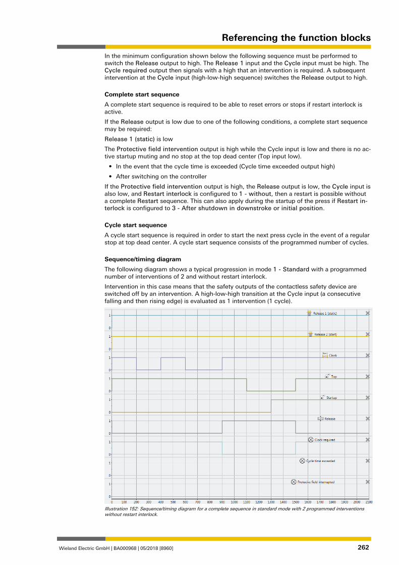
Referencing the function blocks
Wieland Electric GmbH | BA000968 | 05/2018 [8960] 262
In the minimum configuration shown below the following sequence must be performed to switch the Release output to high. The Release 1 input and the Cycle input must be high. The Cycle required output then signals with a high that an intervention is required. A subsequent intervention at the Cycle input (high-low-high sequence) switches the Release output to high.
Complete start sequence
A complete start sequence is required to be able to reset errors or stops if restart interlock is active.
If the Release output is low due to one of the following conditions, a complete start sequence may be required:
Release 1 (static) is low
The Protective field intervention output is high while the Cycle input is low and there is no ac-tive startup muting and no stop at the top dead center (Top input low).
• In the event that the cycle time is exceeded (Cycle time exceeded output high)
• After switching on the controller
If the Protective field intervention output is high, the Release output is low, the Cycle input is also low, and Restart interlock is configured to 1 - without, then a restart is possible without a complete Restart sequence. This can also apply during the startup of the press if Restart in-terlock is configured to 3 - After shutdown in downstroke or initial position.
Cycle start sequence
A cycle start sequence is required in order to start the next press cycle in the event of a regular stop at top dead center. A cycle start sequence consists of the programmed number of cycles.
Sequence/timing diagram
The following diagram shows a typical progression in mode 1 - Standard with a programmed number of interventions of 2 and without restart interlock.
Intervention in this case means that the safety outputs of the contactless safety device are switched off by an intervention. A high-low-high transition at the Cycle input (a consecutive falling and then rising edge) is evaluated as 1 intervention (1 cycle).
Illustration 152: Sequence/timing diagram for a complete sequence in standard mode with 2 programmed interventions without restart interlock.
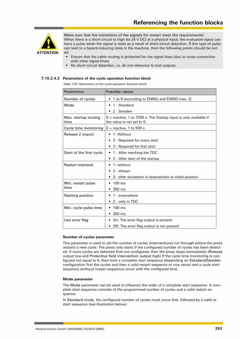
Referencing the function blocks
Wieland Electric GmbH | BA000968 | 05/2018 [8960] 263
ATTENTION
Make sure that the transitions of the signals for restart meet the requirements! When there is a short-circuit to high (to 24 V DC) at a physical input, the evaluated signal can have a pulse when the signal is reset as a result of short-circuit detection. If this type of pulse can lead to a hazard-inducing state in the machine, then the following points should be not-ed: • Ensure that the cable routing is protected for the signal lines (due to cross-connection
with other signal lines). • No short-circuit detection, i.e. do not reference to test outputs.
1076907531
Parameters of the cycle operation function block Table 129: Parameters of the cycle operation function block
Parameters Possible values
Number of cycles • 1 to 8 (according to EN692 and EN693 max. 2)
Mode • 1 - Standard
• 2 - Sweden
Max. startup muting time
0 = inactive, 1 to 7200 s. The Startup input is only available if the value is not set to 0.
Cycle time monitoring 0 = inactive, 1 to 500 s
Release 2 (input) • 1- Without
• 2 - Required for every start
• 3 - Required for first start
Start of the first cycle • 1 - After reaching the TDC
• 2 - After start of the startup
Restart interlock • 1- without
• 2 - always
• 3 - after shutdown in downstroke or initial position
Min. restart pulse time
• 100 ms
• 350 ms
Starting position • 1 - everywhere
• 2 - only in TDC
Min. cycle pulse time • 100 ms
• 350 ms
Use error flag • On: The error flag output is present
• Off: The error flag output is not present
Number of cycles parameter
This parameter is used to set the number of cycles (interventions) run through before the press restarts a new cycle. The press only starts if the configured number of cycles has been detect-ed. If more cycles are detected than are configured, then the press stops immediately (Release output low and Protective field intervention output high) If the cycle time monitoring is con-figured not equal to 0, then both a complete start sequence (depending on Standard/Sweden configuration first the cycles and then a valid restart sequence or vice versa) and a cycle start sequence (without restart sequence) occur with the configured time.
Mode parameter
The Mode parameter can be used to influence the order of a complete start sequence. A com-plete start sequence consists of the programmed number of cycles and a valid restart se-quence.
In Standard mode, the configured number of cycles must occur first, followed by a valid re-start sequence (see illustration below).
7.10.2.4.2
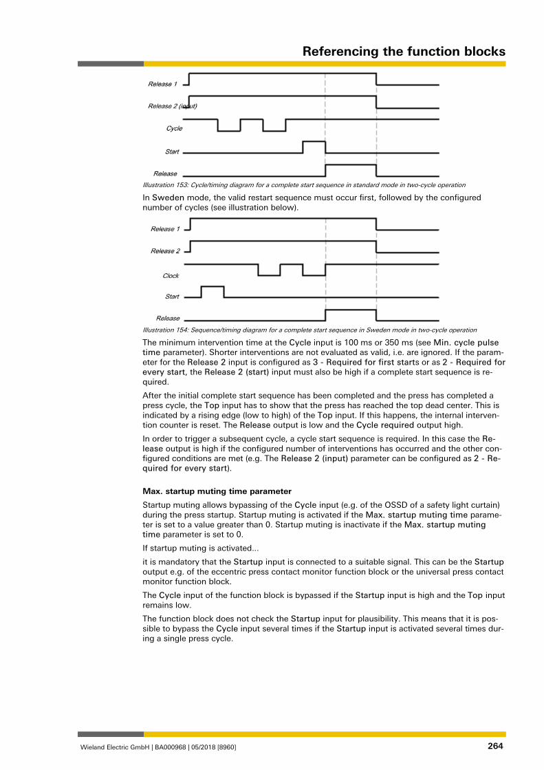
Referencing the function blocks
Wieland Electric GmbH | BA000968 | 05/2018 [8960] 264
Illustration 153: Cycle/timing diagram for a complete start sequence in standard mode in two-cycle operation
In Sweden mode, the valid restart sequence must occur first, followed by the configured number of cycles (see illustration below).
Illustration 154: Sequence/timing diagram for a complete start sequence in Sweden mode in two-cycle operation
The minimum intervention time at the Cycle input is 100 ms or 350 ms (see Min. cycle pulse time parameter). Shorter interventions are not evaluated as valid, i.e. are ignored. If the param-eter for the Release 2 input is configured as 3 - Required for first starts or as 2 - Required for every start, the Release 2 (start) input must also be high if a complete start sequence is re-quired.
After the initial complete start sequence has been completed and the press has completed a press cycle, the Top input has to show that the press has reached the top dead center. This is indicated by a rising edge (low to high) of the Top input. If this happens, the internal interven-tion counter is reset. The Release output is low and the Cycle required output high.
In order to trigger a subsequent cycle, a cycle start sequence is required. In this case the Re-lease output is high if the configured number of interventions has occurred and the other con-figured conditions are met (e.g. The Release 2 (input) parameter can be configured as 2 - Re-quired for every start).
Max. startup muting time parameter
Startup muting allows bypassing of the Cycle input (e.g. of the OSSD of a safety light curtain) during the press startup. Startup muting is activated if the Max. startup muting time parame-ter is set to a value greater than 0. Startup muting is inactivate if the Max. startup muting time parameter is set to 0.
If startup muting is activated...
it is mandatory that the Startup input is connected to a suitable signal. This can be the Startup output e.g. of the eccentric press contact monitor function block or the universal press contact monitor function block.
The Cycle input of the function block is bypassed if the Startup input is high and the Top input remains low.
The function block does not check the Startup input for plausibility. This means that it is pos-sible to bypass the Cycle input several times if the Startup input is activated several times dur-ing a single press cycle.
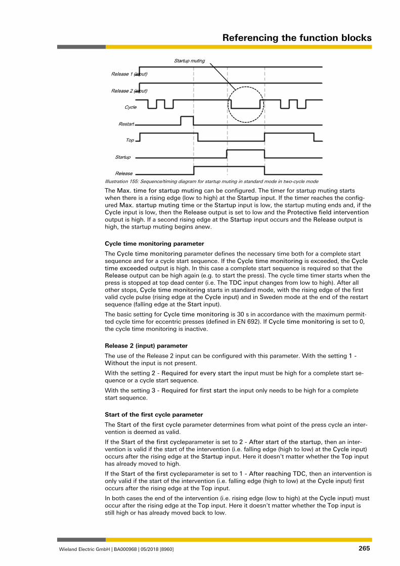
Referencing the function blocks
Wieland Electric GmbH | BA000968 | 05/2018 [8960] 265
Illustration 155: Sequence/timing diagram for startup muting in standard mode in two-cycle mode
The Max. time for startup muting can be configured. The timer for startup muting starts when there is a rising edge (low to high) at the Startup input. If the timer reaches the config-ured Max. startup muting time or the Startup input is low, the startup muting ends and, if the Cycle input is low, then the Release output is set to low and the Protective field intervention output is high. If a second rising edge at the Startup input occurs and the Release output is high, the startup muting begins anew.
Cycle time monitoring parameter
The Cycle time monitoring parameter defines the necessary time both for a complete start sequence and for a cycle start sequence. If the Cycle time monitoring is exceeded, the Cycle time exceeded output is high. In this case a complete start sequence is required so that the Release output can be high again (e.g. to start the press). The cycle time timer starts when the press is stopped at top dead center (i.e. The TDC input changes from low to high). After all other stops, Cycle time monitoring starts in standard mode, with the rising edge of the first valid cycle pulse (rising edge at the Cycle input) and in Sweden mode at the end of the restart sequence (falling edge at the Start input).
The basic setting for Cycle time monitoring is 30 s in accordance with the maximum permit-ted cycle time for eccentric presses (defined in EN 692). If Cycle time monitoring is set to 0, the cycle time monitoring is inactive.
Release 2 (input) parameter
The use of the Release 2 input can be configured with this parameter. With the setting 1 - Without the input is not present.
With the setting 2 - Required for every start the input must be high for a complete start se-quence or a cycle start sequence.
With the setting 3 - Required for first start the input only needs to be high for a complete start sequence.
Start of the first cycle parameter
The Start of the first cycle parameter determines from what point of the press cycle an inter-vention is deemed as valid.
If the Start of the first cycleparameter is set to 2 - After start of the startup, then an inter-vention is valid if the start of the intervention (i.e. falling edge (high to low) at the Cycle input) occurs after the rising edge at the Startup input. Here it doesn't matter whether the Top input has already moved to high.
If the Start of the first cycleparameter is set to 1 - After reaching TDC, then an intervention is only valid if the start of the intervention (i.e. falling edge (high to low) at the Cycle input) first occurs after the rising edge at the Top input.
In both cases the end of the intervention (i.e. rising edge (low to high) at the Cycle input) must occur after the rising edge at the Top input. Here it doesn't matter whether the Top input is still high or has already moved back to low.
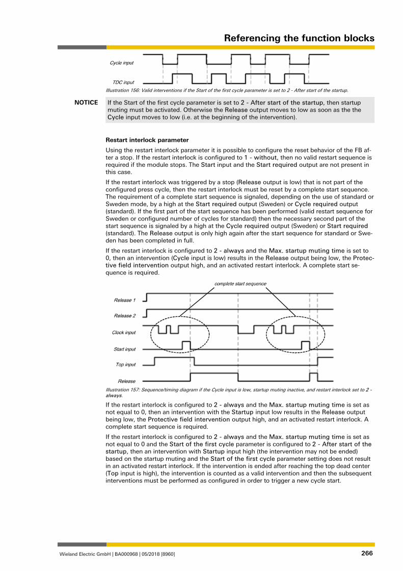
Referencing the function blocks
Wieland Electric GmbH | BA000968 | 05/2018 [8960] 266
Illustration 156: Valid interventions if the Start of the first cycle parameter is set to 2 - After start of the startup.
NOTICE If the Start of the first cycle parameter is set to 2 - After start of the startup, then startup muting must be activated. Otherwise the Release output moves to low as soon as the the Cycle input moves to low (i.e. at the beginning of the intervention).
Restart interlock parameter
Using the restart interlock parameter it is possible to configure the reset behavior of the FB af-ter a stop. If the restart interlock is configured to 1 - without, then no valid restart sequence is required if the module stops. The Start input and the Start required output are not present in this case.
If the restart interlock was triggered by a stop (Release output is low) that is not part of the configured press cycle, then the restart interlock must be reset by a complete start sequence. The requirement of a complete start sequence is signaled, depending on the use of standard or Sweden mode, by a high at the Start required output (Sweden) or Cycle required output (standard). If the first part of the start sequence has been performed (valid restart sequence for Sweden or configured number of cycles for standard) then the necessary second part of the start sequence is signaled by a high at the Cycle required output (Sweden) or Start required (standard). The Release output is only high again after the start sequence for standard or Swe-den has been completed in full.
If the restart interlock is configured to 2 - always and the Max. startup muting time is set to 0, then an intervention (Cycle input is low) results in the Release output being low, the Protec-tive field intervention output high, and an activated restart interlock. A complete start se-quence is required.
Illustration 157: Sequence/timing diagram if the Cycle input is low, startup muting inactive, and restart interlock set to 2 - always.
If the restart interlock is configured to 2 - always and the Max. startup muting time is set as not equal to 0, then an intervention with the Startup input low results in the Release output being low, the Protective field intervention output high, and an activated restart interlock. A complete start sequence is required.
If the restart interlock is configured to 2 - always and the Max. startup muting time is set as not equal to 0 and the Start of the first cycle parameter is configured to 2 - After start of the startup, then an intervention with Startup input high (the intervention may not be ended) based on the startup muting and the Start of the first cycle parameter setting does not result in an activated restart interlock. If the intervention is ended after reaching the top dead center (Top input is high), the intervention is counted as a valid intervention and then the subsequent interventions must be performed as configured in order to trigger a new cycle start.
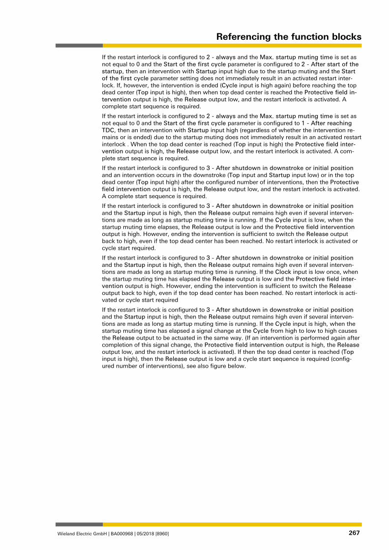
Referencing the function blocks
Wieland Electric GmbH | BA000968 | 05/2018 [8960] 267
If the restart interlock is configured to 2 - always and the Max. startup muting time is set as not equal to 0 and the Start of the first cycle parameter is configured to 2 - After start of the startup, then an intervention with Startup input high due to the startup muting and the Start of the first cycle parameter setting does not immediately result in an activated restart inter-lock. If, however, the intervention is ended (Cycle input is high again) before reaching the top dead center (Top input is high), then when top dead center is reached the Protective field in-tervention output is high, the Release output low, and the restart interlock is activated. A complete start sequence is required.
If the restart interlock is configured to 2 - always and the Max. startup muting time is set as not equal to 0 and the Start of the first cycle parameter is configured to 1 - After reaching TDC, then an intervention with Startup input high (regardless of whether the intervention re-mains or is ended) due to the startup muting does not immediately result in an activated restart interlock . When the top dead center is reached (Top input is high) the Protective field inter-vention output is high, the Release output low, and the restart interlock is activated. A com-plete start sequence is required.
If the restart interlock is configured to 3 - After shutdown in downstroke or initial position and an intervention occurs in the downstroke (Top input and Startup input low) or in the top dead center (Top input high) after the configured number of interventions, then the Protective field intervention output is high, the Release output low, and the restart interlock is activated. A complete start sequence is required.
If the restart interlock is configured to 3 - After shutdown in downstroke or initial position and the Startup input is high, then the Release output remains high even if several interven-tions are made as long as startup muting time is running. If the Cycle input is low, when the startup muting time elapses, the Release output is low and the Protective field intervention output is high. However, ending the intervention is sufficient to switch the Release output back to high, even if the top dead center has been reached. No restart interlock is activated or cycle start required.
If the restart interlock is configured to 3 - After shutdown in downstroke or initial position and the Startup input is high, then the Release output remains high even if several interven-tions are made as long as startup muting time is running. If the Clock input is low once, when the startup muting time has elapsed the Release output is low and the Protective field inter-vention output is high. However, ending the intervention is sufficient to switch the Release output back to high, even if the top dead center has been reached. No restart interlock is acti-vated or cycle start required
If the restart interlock is configured to 3 - After shutdown in downstroke or initial position and the Startup input is high, then the Release output remains high even if several interven-tions are made as long as startup muting time is running. If the Cycle input is high, when the startup muting time has elapsed a signal change at the Cycle from high to low to high causes the Release output to be actuated in the same way. (If an intervention is performed again after completion of this signal change, the Protective field intervention output is high, the Release output low, and the restart interlock is activated). If then the top dead center is reached (Top input is high), then the Release output is low and a cycle start sequence is required (config-ured number of interventions), see also figure below.
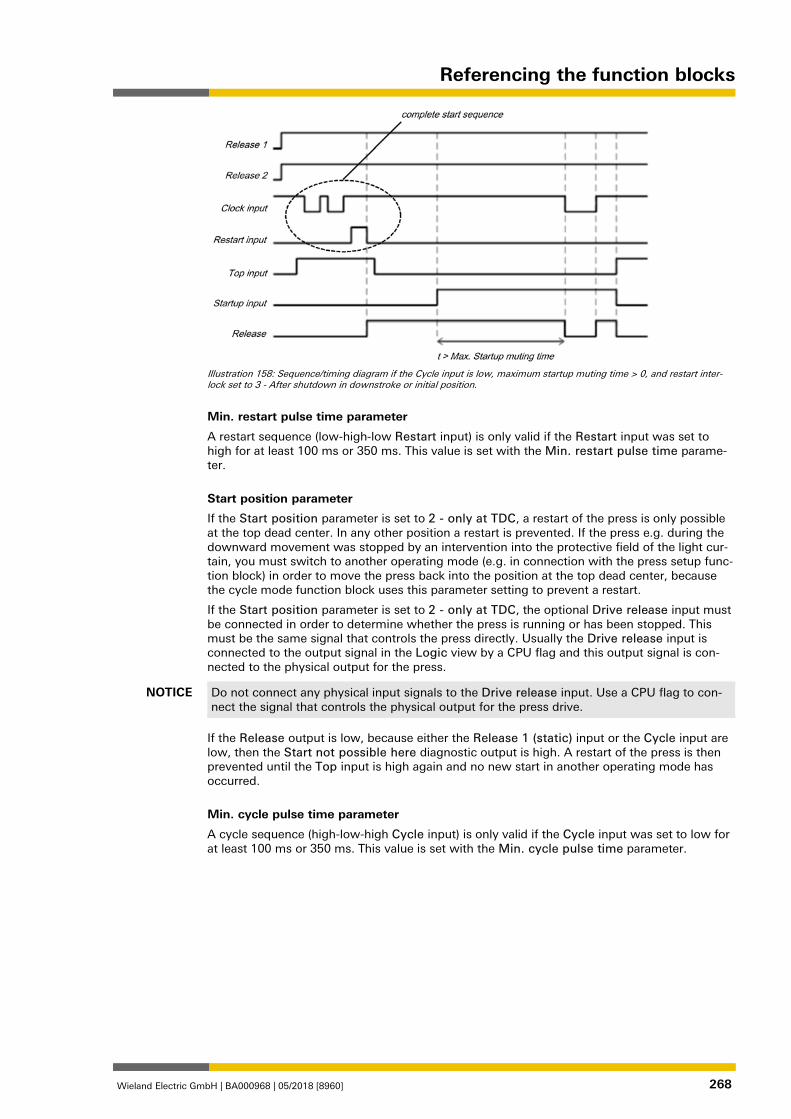
Referencing the function blocks
Wieland Electric GmbH | BA000968 | 05/2018 [8960] 268
Illustration 158: Sequence/timing diagram if the Cycle input is low, maximum startup muting time > 0, and restart inter-lock set to 3 - After shutdown in downstroke or initial position.
Min. restart pulse time parameter
A restart sequence (low-high-low Restart input) is only valid if the Restart input was set to high for at least 100 ms or 350 ms. This value is set with the Min. restart pulse time parame-ter.
Start position parameter
If the Start position parameter is set to 2 - only at TDC, a restart of the press is only possible at the top dead center. In any other position a restart is prevented. If the press e.g. during the downward movement was stopped by an intervention into the protective field of the light cur-tain, you must switch to another operating mode (e.g. in connection with the press setup func-tion block) in order to move the press back into the position at the top dead center, because the cycle mode function block uses this parameter setting to prevent a restart.
If the Start position parameter is set to 2 - only at TDC, the optional Drive release input must be connected in order to determine whether the press is running or has been stopped. This must be the same signal that controls the press directly. Usually the Drive release input is connected to the output signal in the Logic view by a CPU flag and this output signal is con-nected to the physical output for the press.
NOTICE Do not connect any physical input signals to the Drive release input. Use a CPU flag to con-nect the signal that controls the physical output for the press drive.
If the Release output is low, because either the Release 1 (static) input or the Cycle input are low, then the Start not possible here diagnostic output is high. A restart of the press is then prevented until the Top input is high again and no new start in another operating mode has occurred.
Min. cycle pulse time parameter
A cycle sequence (high-low-high Cycle input) is only valid if the Cycle input was set to low for at least 100 ms or 350 ms. This value is set with the Min. cycle pulse time parameter. 1076918539
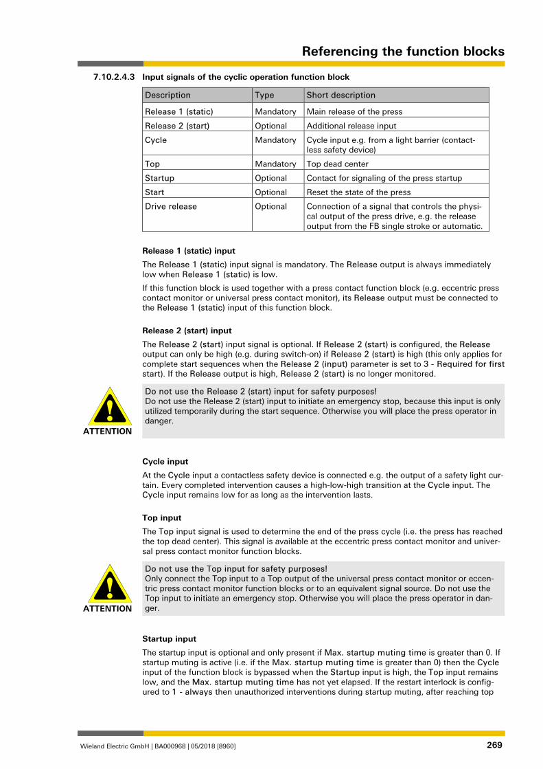
Referencing the function blocks
Wieland Electric GmbH | BA000968 | 05/2018 [8960] 269
Input signals of the cyclic operation function block
Description Type Short description
Release 1 (static) Mandatory Main release of the press
Release 2 (start) Optional Additional release input
Cycle Mandatory Cycle input e.g. from a light barrier (contact-less safety device)
Top Mandatory Top dead center
Startup Optional Contact for signaling of the press startup
Start Optional Reset the state of the press
Drive release Optional Connection of a signal that controls the physi-cal output of the press drive, e.g. the release output from the FB single stroke or automatic.
Release 1 (static) input
The Release 1 (static) input signal is mandatory. The Release output is always immediately low when Release 1 (static) is low.
If this function block is used together with a press contact function block (e.g. eccentric press contact monitor or universal press contact monitor), its Release output must be connected to the Release 1 (static) input of this function block.
Release 2 (start) input
The Release 2 (start) input signal is optional. If Release 2 (start) is configured, the Release output can only be high (e.g. during switch-on) if Release 2 (start) is high (this only applies for complete start sequences when the Release 2 (input) parameter is set to 3 - Required for first start). If the Release output is high, Release 2 (start) is no longer monitored.
ATTENTION
Do not use the Release 2 (start) input for safety purposes! Do not use the Release 2 (start) input to initiate an emergency stop, because this input is only utilized temporarily during the start sequence. Otherwise you will place the press operator in danger.
Cycle input
At the Cycle input a contactless safety device is connected e.g. the output of a safety light cur-tain. Every completed intervention causes a high-low-high transition at the Cycle input. The Cycle input remains low for as long as the intervention lasts.
Top input
The Top input signal is used to determine the end of the press cycle (i.e. the press has reached the top dead center). This signal is available at the eccentric press contact monitor and univer-sal press contact monitor function blocks.
ATTENTION
Do not use the Top input for safety purposes! Only connect the Top input to a Top output of the universal press contact monitor or eccen-tric press contact monitor function blocks or to an equivalent signal source. Do not use the Top input to initiate an emergency stop. Otherwise you will place the press operator in dan-ger.
Startup input
The startup input is optional and only present if Max. startup muting time is greater than 0. If startup muting is active (i.e. if the Max. startup muting time is greater than 0) then the Cycle input of the function block is bypassed when the Startup input is high, the Top input remains low, and the Max. startup muting time has not yet elapsed. If the restart interlock is config-ured to 1 - always then unauthorized interventions during startup muting, after reaching top
7.10.2.4.3
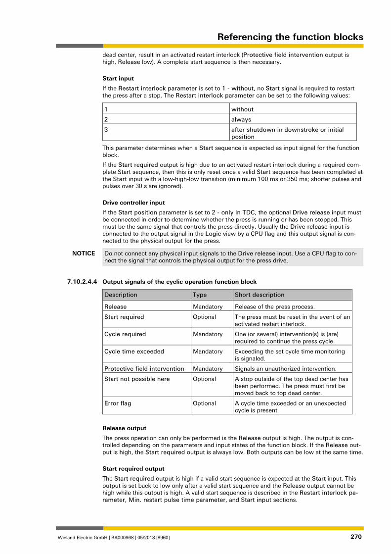
Referencing the function blocks
Wieland Electric GmbH | BA000968 | 05/2018 [8960] 270
dead center, result in an activated restart interlock (Protective field intervention output is high, Release low). A complete start sequence is then necessary.
Start input
If the Restart interlock parameter is set to 1 - without, no Start signal is required to restart the press after a stop. The Restart interlock parameter can be set to the following values:
1 without
2 always
3 after shutdown in downstroke or initial position
This parameter determines when a Start sequence is expected as input signal for the function block.
If the Start required output is high due to an activated restart interlock during a required com-plete Start sequence, then this is only reset once a valid Start sequence has been completed at the Start input with a low-high-low transition (minimum 100 ms or 350 ms; shorter pulses and pulses over 30 s are ignored).
Drive controller input
If the Start position parameter is set to 2 - only in TDC, the optional Drive release input must be connected in order to determine whether the press is running or has been stopped. This must be the same signal that controls the press directly. Usually the Drive release input is connected to the output signal in the Logic view by a CPU flag and this output signal is con-nected to the physical output for the press.
NOTICE Do not connect any physical input signals to the Drive release input. Use a CPU flag to con-nect the signal that controls the physical output for the press drive.
1076920075
Output signals of the cyclic operation function block
Description Type Short description
Release Mandatory Release of the press process.
Start required Optional The press must be reset in the event of an activated restart interlock.
Cycle required Mandatory One (or several) intervention(s) is (are) required to continue the press cycle.
Cycle time exceeded Mandatory Exceeding the set cycle time monitoring is signaled.
Protective field intervention Mandatory Signals an unauthorized intervention.
Start not possible here Optional A stop outside of the top dead center has been performed. The press must first be moved back to top dead center.
Error flag Optional A cycle time exceeded or an unexpected cycle is present
Release output
The press operation can only be performed is the Release output is high. The output is con-trolled depending on the parameters and input states of the function block. If the Release out-put is high, the Start required output is always low. Both outputs can be low at the same time.
Start required output
The Start required output is high if a valid start sequence is expected at the Start input. This output is set back to low only after a valid start sequence and the Release output cannot be high while this output is high. A valid start sequence is described in the Restart interlock pa-rameter, Min. restart pulse time parameter, and Start input sections.
7.10.2.4.4
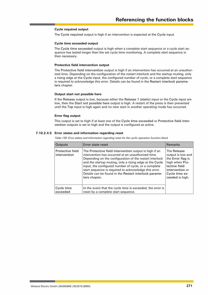
Referencing the function blocks
Wieland Electric GmbH | BA000968 | 05/2018 [8960] 271
Cycle required output
The Cycle required output is high if an intervention is expected at the Cycle input.
Cycle time exceeded output
The Cycle time exceeded output is high when a complete start sequence or a cycle start se-quence has lasted longer than the set cycle time monitoring. A complete start sequence is then necessary.
Protective field intervention output
The Protective field intervention output is high if an intervention has occurred at an unauthor-ized time. Depending on the configuration of the restart interlock and the startup muting, only a rising edge at the Cycle input, the configured number of cycle, or a complete start sequence is required to acknowledge this error. Details can be found in the Restart interlock parame-ters chapter.
Output start not possible here
If the Release output is low, because either the Release 1 (static) input or the Cycle input are low, then the Start not possible here output is high. A restart of the press is then prevented until the Top input is high again and no new start in another operating mode has occurred.
Error flag output
This output is set to high if at least one of the Cycle time exceeded or Protective field inter-vention outputs is set to high and the output is configured as active. 1076921611
Error states and information regarding reset Table 130: Error states and information regarding reset for the cyclic operation function block
Outputs Error state reset Remarks
Protective field intervention
The Protective field intervention output is high if an intervention has occurred at an unauthorized time. Depending on the configuration of the restart interlock and the startup muting, only a rising edge at the Cycle input, the configured number of cycle, or a complete start sequence is required to acknowledge this error. Details can be found in the Restart interlock parame-ters chapter.
The Release output is low and the Error flag is high when Pro-tective field intervention or Cycle time ex-ceeded is high.
Cycle time exceeded
In the event that the cycle time is exceeded, the error is reset by a complete start sequence.
7.10.2.4.5
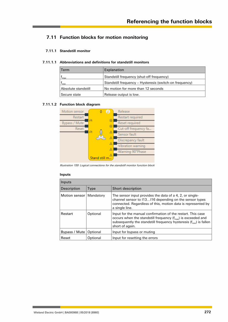
Referencing the function blocks
Wieland Electric GmbH | BA000968 | 05/2018 [8960] 272
Function blocks for motion monitoring 1268992267
Standstill monitor 1268573963
1268575499
Abbreviations and definitions for standstill monitors
Term Explanation
fmax Standstill frequency (shut-off frequency)
fmin Standstill frequency – Hysteresis (switch-on frequency)
Absolute standstill No motion for more than 12 seconds
Secure state Release output is low.
1268577035
Function block diagram
Illustration 159: Logical connections for the standstill monitor function block
Inputs
Inputs
Description Type Short description
Motion sensor Mandatory The sensor input provides the data of a 4, 2, or single-channel sensor to I13…I16 depending on the sensor types connected. Regardless of this, motion data is represented by a single line.
Restart Optional Input for the manual confirmation of the restart. This case occurs when the standstill frequency (fmax) is exceeded and subsequently the standstill frequency hysteresis (fmin) is fallen short of again.
Bypass / Mute Optional Input for bypass or muting
Reset Optional Input for resetting the errors
7.11
7.11.1
7.11.1.1
7.11.1.2
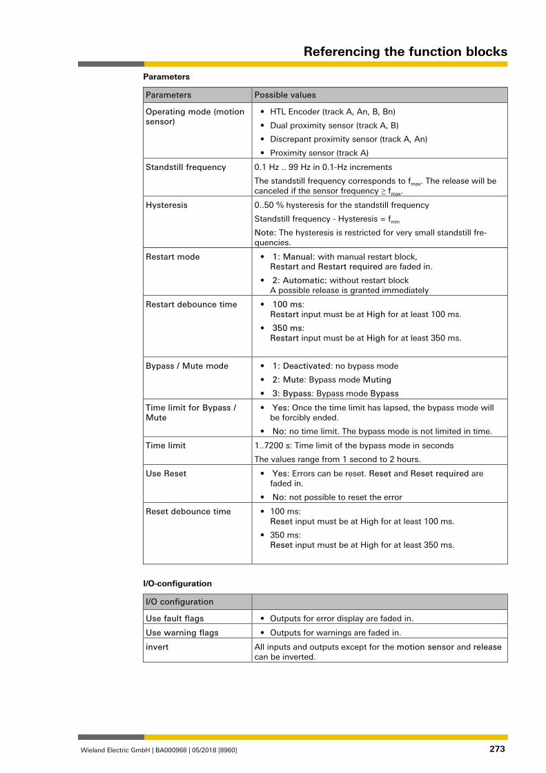
Referencing the function blocks
Wieland Electric GmbH | BA000968 | 05/2018 [8960] 273
Parameters
Parameters Possible values
Operating mode (motion sensor)
• HTL Encoder (track A, An, B, Bn)
• Dual proximity sensor (track A, B)
• Discrepant proximity sensor (track A, An)
• Proximity sensor (track A)
Standstill frequency 0.1 Hz .. 99 Hz in 0.1-Hz increments
The standstill frequency corresponds to fmax. The release will be canceled if the sensor frequency ≥ fmax.
Hysteresis 0..50 % hysteresis for the standstill frequency
Standstill frequency - Hysteresis = fmin
Note: The hysteresis is restricted for very small standstill fre-quencies.
Restart mode • 1: Manual: with manual restart block, Restart and Restart required are faded in.
• 2: Automatic: without restart block A possible release is granted immediately
Restart debounce time • 100 ms: Restart input must be at High for at least 100 ms.
• 350 ms: Restart input must be at High for at least 350 ms.
Bypass / Mute mode • 1: Deactivated: no bypass mode
• 2: Mute: Bypass mode Muting
• 3: Bypass: Bypass mode Bypass
Time limit for Bypass / Mute
• Yes: Once the time limit has lapsed, the bypass mode will be forcibly ended.
• No: no time limit. The bypass mode is not limited in time.
Time limit 1..7200 s: Time limit of the bypass mode in seconds
The values range from 1 second to 2 hours.
Use Reset • Yes: Errors can be reset. Reset and Reset required are faded in.
• No: not possible to reset the error
Reset debounce time • 100 ms: Reset input must be at High for at least 100 ms.
• 350 ms: Reset input must be at High for at least 350 ms.
I/O-configuration
I/O configuration
Use fault flags • Outputs for error display are faded in.
Use warning flags • Outputs for warnings are faded in.
invert All inputs and outputs except for the motion sensor and release can be inverted.
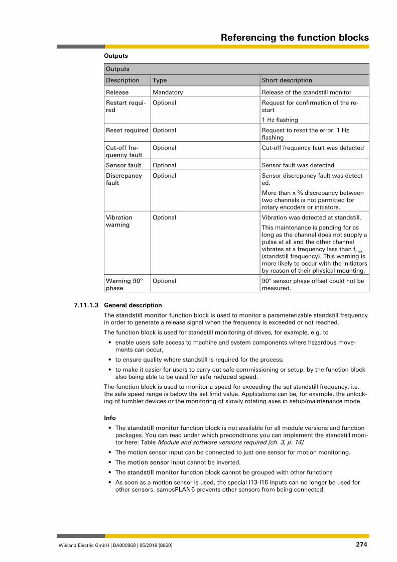
Referencing the function blocks
Wieland Electric GmbH | BA000968 | 05/2018 [8960] 274
Outputs
Outputs
Description Type Short description
Release Mandatory Release of the standstill monitor
Restart requi-red
Optional Request for confirmation of the re-start
1 Hz flashing
Reset required Optional Request to reset the error. 1 Hz flashing
Cut-off fre-quency fault
Optional Cut-off frequency fault was detected
Sensor fault Optional Sensor fault was detected
Discrepancy fault
Optional Sensor discrepancy fault was detect-ed.
More than x % discrepancy between two channels is not permitted for rotary encoders or initiators.
Vibration warning
Optional Vibration was detected at standstill.
This maintenance is pending for as long as the channel does not supply a pulse at all and the other channel vibrates at a frequency less than fmax (standstill frequency). This warning is more likely to occur with the initiators by reason of their physical mounting.
Warning 90° phase
Optional 90° sensor phase offset could not be measured.
1268579723
General description
The standstill monitor function block is used to monitor a parameterizable standstill frequency in order to generate a release signal when the frequency is exceeded or not reached.
The function block is used for standstill monitoring of drives, for example, e.g. to
• enable users safe access to machine and system components where hazardous move-ments can occur,
• to ensure quality where standstill is required for the process,
• to make it easier for users to carry out safe commissioning or setup, by the function block also being able to be used for safe reduced speed.
The function block is used to monitor a speed for exceeding the set standstill frequency, i.e. the safe speed range is below the set limit value. Applications can be, for example, the unlock-ing of tumbler devices or the monitoring of slowly rotating axes in setup/maintenance mode.
Info
• The standstill monitor function block is not available for all module versions and function packages. You can read under which preconditions you can implement the standstill moni-tor here: Table Module and software versions required [ch. 3, p. 14]
• The motion sensor input can be connected to just one sensor for motion monitoring.
• The motion sensor input cannot be inverted.
• The standstill monitor function block cannot be grouped with other functions
• As soon as a motion sensor is used, the special I13-I16 inputs can no longer be used for other sensors. samosPLAN 6 prevents other sensors from being connected.
7.11.1.3
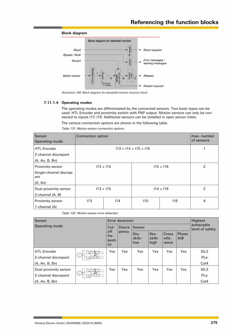
Referencing the function blocks
Wieland Electric GmbH | BA000968 | 05/2018 [8960] 275
Block diagram
Illustration 160: Block diagram for standstill-monitor function block
1268595211
Operating modes
The operating modes are differentiated by the connected sensors. Two basic types can be used: HTL Encoder and proximity switch with PNP output. Motion sensors can only be con-nected to inputs I13..I16. Additional sensors can be installed in open sensor inlets.
The various connection options are shown in the following table.
Table 131: Motion-sensor connection options
Sensor
Operating mode
Connection option max. number of sensors
HTL Encoder
2-channel discrepant
(A, An, B, Bn)
I13 + I14 + I15 + I16 1
Proximity sensor
Single-channel discrep-ant
(A, An)
I13 + I14 I15 + I16 2
Dual proximity sensor
2-channel (A, B)
I13 + I15 I14 + I16 2
Proximity sensor
1-channel (A)
I13 I14 I15 I16 4
Table 132: Motion-sensor error detection
Sensor
Operating mode
Error detection Highest achievable level of safety Cut-
off fre-quency
Discrepancy
Sensor
Stu-ckAt-low
Stu-ckAt-high
Cross refe-rence
Phase A/B
HTL Encoder
2-channel discrepant
(A, An, B, Bn)
Yes Yes Yes Yes Yes Yes SIL3
PLe
Cat4
Dual proximity sensor
2-channel discrepant
(A, An, B, Bn)
Yes Yes Yes Yes Yes Yes SIL3
PLe
Cat4
7.11.1.4
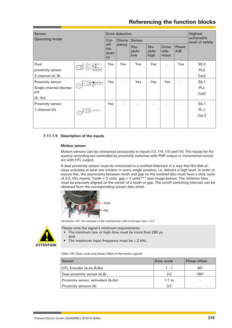
Referencing the function blocks
Wieland Electric GmbH | BA000968 | 05/2018 [8960] 276
Sensor
Operating mode
Error detection Highest achievable level of safety Cut-
off fre-quency
Discrepancy
Sensor
Stu-ckAt-low
Stu-ckAt-high
Cross refe-rence
Phase A/B
Dual
proximity sensor
2-channel (A, B)
Yes Yes Yes Yes - Yes SIL2
PLd
Cat3
Proximity sensor
Single-channel discrep-ant
(A, An)
Yes - Yes Yes Yes - SIL1
PLc
Cat2
Proximity sensor
1-channel (A)
Yes - - - - - SIL1
PL c
Cat 2
1268604555
Description of the inputs
Motion sensor
Motion sensors can be connected exclusively to inputs I13, I14, I15 and I16. The inputs for fre-quency recording are controlled by proximity switches with PNP output or incremental encod-ers with HTL output.
A dual proximity sensor must be connected to a toothed disk/rack in a way that the disk al-ways activates at least one initiator in every single position, i.e. delivers a high level. In order to ensure this, the asymmetry between tooth and gap on the toothed disc must have a duty cycle of 3:2; this means: Tooth = 3 units, gap = 2 units*** (see image below). The initiators here must be precisely aligned on the center of a tooth or gap. The on/off switching intervals can be obtained from the corresponding sensor data sheet.
Illustration 161: An example of the toothed disc with tooth:gap ratio = 3:2.
ATTENTION
Please note the signal's minimum requirements: • The minimum low or high time must be more than 200 µs.
and • The maximum input frequency must be ≤ 2 kHz.
Table 133: Duty cycle and phase offset of the sensor signals
Sensor Duty cycle Phase offset
HTL Encoder (A,An,B,Bn) 1 : 1 90°
Dual proximity sensor (A,B) 3:2 180°
Proximity sensor, antivalent (A,An)
Proximity sensors (A)
1:1 to
3:2
-
7.11.1.5
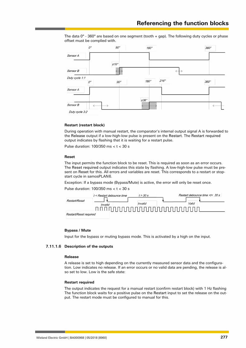
Referencing the function blocks
Wieland Electric GmbH | BA000968 | 05/2018 [8960] 277
The data 0° - 360° are based on one segment (tooth + gap). The following duty cycles or phase offset must be complied with.
Restart (restart block)
During operation with manual restart, the comparator's internal output signal A is forwarded to the Release output if a low-high-low pulse is present on the Restart. The Restart required output indicates by flashing that it is waiting for a restart pulse.
Pulse duration: 100/350 ms < t < 30 s
Reset
The input permits the function block to be reset. This is required as soon as an error occurs. The Reset required output indicates this state by flashing. A low-high-low pulse must be pre-sent on Reset for this. All errors and variables are reset. This corresponds to a restart or stop-start cycle in samosPLAN 6.
Exception: If a bypass mode (Bypass/Mute) is active, the error will only be reset once.
Pulse duration: 100/350 ms < t < 30 s
Bypass / Mute
Input for the bypass or muting bypass mode. This is activated by a high on the input. 1268612235
Description of the outputs
Release
A release is set to high depending on the currently measured sensor data and the configura-tion. Low indicates no release. If an error occurs or no valid data are pending, the release is al-so set to low. Low is the safe state:
Restart required
The output indicates the request for a manual restart (confirm restart block) with 1 Hz flashing The function block waits for a positive pulse on the Restart input to set the release on the out-put. The restart mode must be configured to manual for this.
7.11.1.6
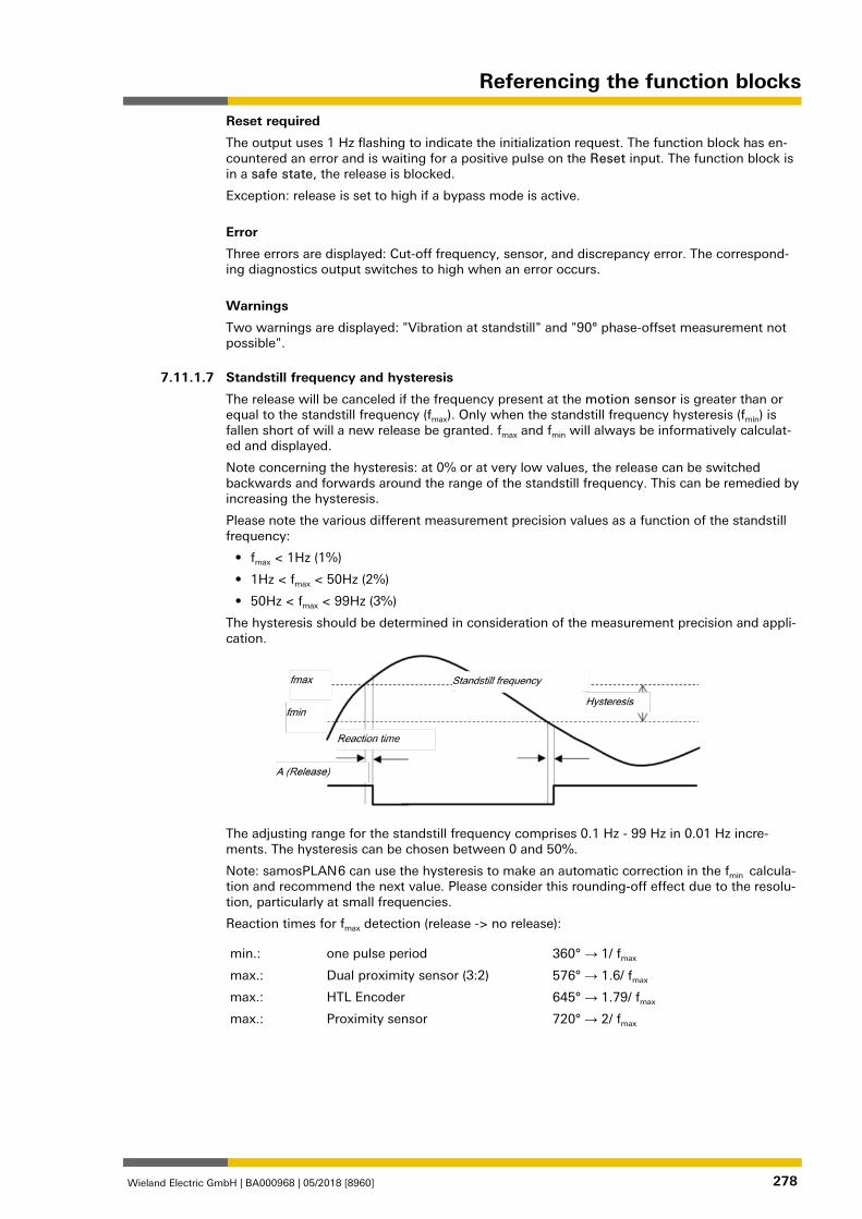
Referencing the function blocks
Wieland Electric GmbH | BA000968 | 05/2018 [8960] 278
Reset required
The output uses 1 Hz flashing to indicate the initialization request. The function block has en-countered an error and is waiting for a positive pulse on the Reset input. The function block is in a safe state, the release is blocked.
Exception: release is set to high if a bypass mode is active.
Error
Three errors are displayed: Cut-off frequency, sensor, and discrepancy error. The correspond-ing diagnostics output switches to high when an error occurs.
Warnings
Two warnings are displayed: "Vibration at standstill" and "90° phase-offset measurement not possible". 1268613771
Standstill frequency and hysteresis
The release will be canceled if the frequency present at the motion sensor is greater than or equal to the standstill frequency (fmax). Only when the standstill frequency hysteresis (fmin) is fallen short of will a new release be granted. fmax and fmin will always be informatively calculat-ed and displayed.
Note concerning the hysteresis: at 0% or at very low values, the release can be switched backwards and forwards around the range of the standstill frequency. This can be remedied by increasing the hysteresis.
Please note the various different measurement precision values as a function of the standstill frequency:
• fmax < 1Hz (1%)
• 1Hz < fmax < 50Hz (2%)
• 50Hz < fmax < 99Hz (3%)
The hysteresis should be determined in consideration of the measurement precision and appli-cation.
The adjusting range for the standstill frequency comprises 0.1 Hz - 99 Hz in 0.01 Hz incre-ments. The hysteresis can be chosen between 0 and 50%.
Note: samosPLAN 6 can use the hysteresis to make an automatic correction in the fmin calcula-tion and recommend the next value. Please consider this rounding-off effect due to the resolu-tion, particularly at small frequencies.
Reaction times for fmax detection (release -> no release):
min.: one pulse period 360° → 1/ fmax
max.: Dual proximity sensor (3:2) 576° → 1.6/ fmax
max.: HTL Encoder 645° → 1.79/ fmax
max.: Proximity sensor 720° → 2/ fmax
1268616459
7.11.1.7
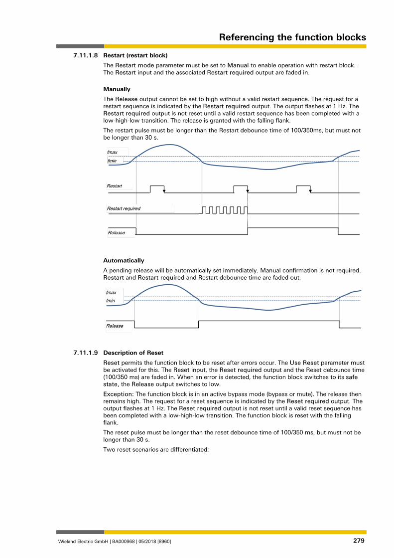
Referencing the function blocks
Wieland Electric GmbH | BA000968 | 05/2018 [8960] 279
Restart (restart block)
The Restart mode parameter must be set to Manual to enable operation with restart block. The Restart input and the associated Restart required output are faded in.
Manually
The Release output cannot be set to high without a valid restart sequence. The request for a restart sequence is indicated by the Restart required output. The output flashes at 1 Hz. The Restart required output is not reset until a valid restart sequence has been completed with a low-high-low transition. The release is granted with the falling flank.
The restart pulse must be longer than the Restart debounce time of 100/350ms, but must not be longer than 30 s.
Automatically
A pending release will be automatically set immediately. Manual confirmation is not required. Restart and Restart required and Restart debounce time are faded out.
1268620811
Description of Reset
Reset permits the function block to be reset after errors occur. The Use Reset parameter must be activated for this. The Reset input, the Reset required output and the Reset debounce time (100/350 ms) are faded in. When an error is detected, the function block switches to its safe state, the Release output switches to low.
Exception: The function block is in an active bypass mode (bypass or mute). The release then remains high. The request for a reset sequence is indicated by the Reset required output. The output flashes at 1 Hz. The Reset required output is not reset until a valid reset sequence has been completed with a low-high-low transition. The function block is reset with the falling flank.
The reset pulse must be longer than the reset debounce time of 100/350 ms, but must not be longer than 30 s.
Two reset scenarios are differentiated:
7.11.1.8
7.11.1.9
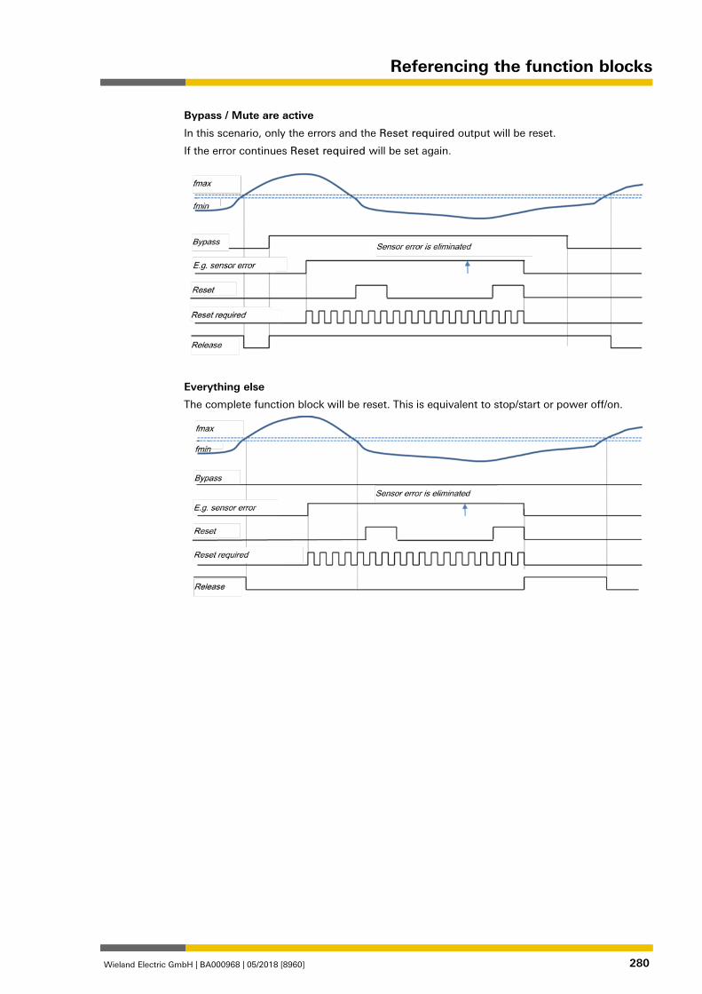
Referencing the function blocks
Wieland Electric GmbH | BA000968 | 05/2018 [8960] 280
Bypass / Mute are active
In this scenario, only the errors and the Reset required output will be reset.
If the error continues Reset required will be set again.
Everything else
The complete function block will be reset. This is equivalent to stop/start or power off/on.
1268625163
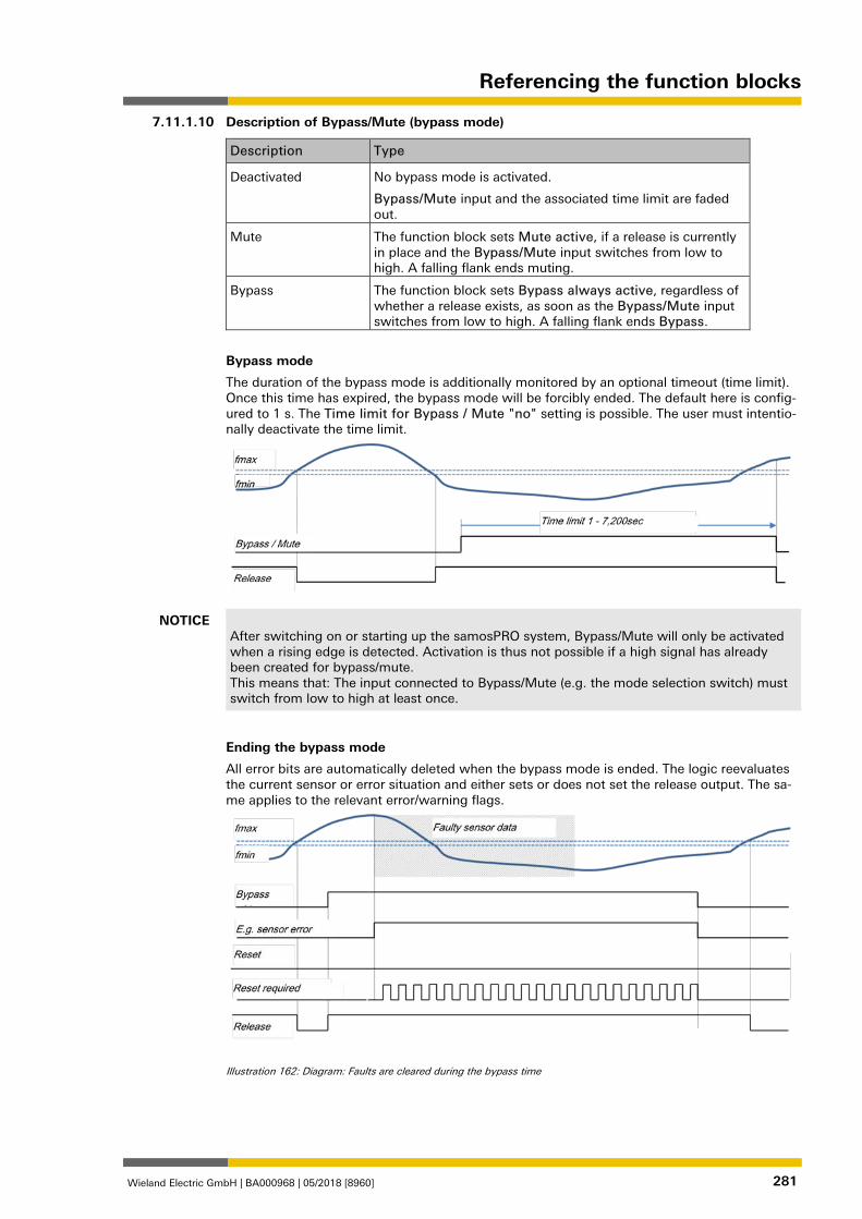
Referencing the function blocks
Wieland Electric GmbH | BA000968 | 05/2018 [8960] 281
Description of Bypass/Mute (bypass mode)
Description Type
Deactivated No bypass mode is activated.
Bypass/Mute input and the associated time limit are faded out.
Mute The function block sets Mute active, if a release is currently in place and the Bypass/Mute input switches from low to high. A falling flank ends muting.
Bypass The function block sets Bypass always active, regardless of whether a release exists, as soon as the Bypass/Mute input switches from low to high. A falling flank ends Bypass.
Bypass mode
The duration of the bypass mode is additionally monitored by an optional timeout (time limit). Once this time has expired, the bypass mode will be forcibly ended. The default here is config-ured to 1 s. The Time limit for Bypass / Mute "no" setting is possible. The user must intentio-nally deactivate the time limit.
NOTICE After switching on or starting up the samosPRO system, Bypass/Mute will only be activated when a rising edge is detected. Activation is thus not possible if a high signal has already been created for bypass/mute. This means that: The input connected to Bypass/Mute (e.g. the mode selection switch) must switch from low to high at least once.
Ending the bypass mode
All error bits are automatically deleted when the bypass mode is ended. The logic reevaluates the current sensor or error situation and either sets or does not set the release output. The sa-me applies to the relevant error/warning flags.
Illustration 162: Diagram: Faults are cleared during the bypass time
7.11.1.10
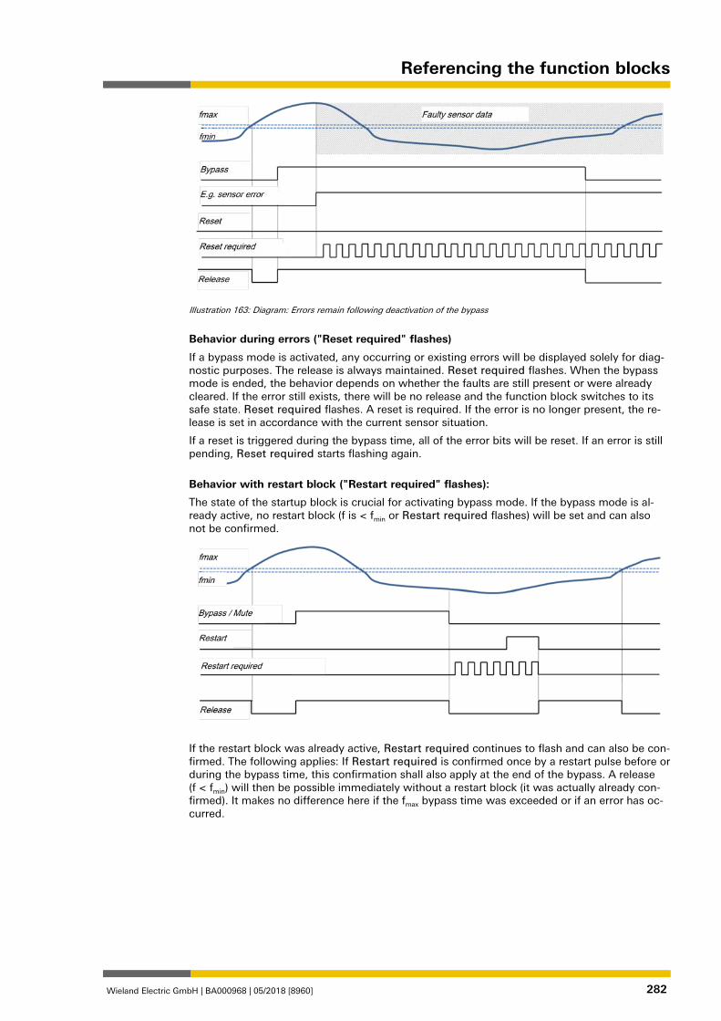
Referencing the function blocks
Wieland Electric GmbH | BA000968 | 05/2018 [8960] 282
Illustration 163: Diagram: Errors remain following deactivation of the bypass
Behavior during errors ("Reset required" flashes)
If a bypass mode is activated, any occurring or existing errors will be displayed solely for diag-nostic purposes. The release is always maintained. Reset required flashes. When the bypass mode is ended, the behavior depends on whether the faults are still present or were already cleared. If the error still exists, there will be no release and the function block switches to its safe state. Reset required flashes. A reset is required. If the error is no longer present, the re-lease is set in accordance with the current sensor situation.
If a reset is triggered during the bypass time, all of the error bits will be reset. If an error is still pending, Reset required starts flashing again.
Behavior with restart block ("Restart required" flashes):
The state of the startup block is crucial for activating bypass mode. If the bypass mode is al-ready active, no restart block (f is < fmin or Restart required flashes) will be set and can also not be confirmed.
If the restart block was already active, Restart required continues to flash and can also be con-firmed. The following applies: If Restart required is confirmed once by a restart pulse before or during the bypass time, this confirmation shall also apply at the end of the bypass. A release (f < fmin) will then be possible immediately without a restart block (it was actually already con-firmed). It makes no difference here if the fmax bypass time was exceeded or if an error has oc-curred.
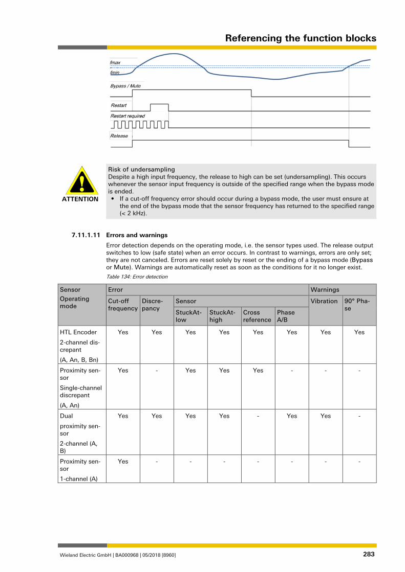
Referencing the function blocks
Wieland Electric GmbH | BA000968 | 05/2018 [8960] 283
ATTENTION
Risk of undersampling Despite a high input frequency, the release to high can be set (undersampling). This occurs whenever the sensor input frequency is outside of the specified range when the bypass mode is ended. • If a cut-off frequency error should occur during a bypass mode, the user must ensure at
the end of the bypass mode that the sensor frequency has returned to the specified range (< 2 kHz).
1268634507
Errors and warnings
Error detection depends on the operating mode, i.e. the sensor types used. The release output switches to low (safe state) when an error occurs. In contrast to warnings, errors are only set; they are not canceled. Errors are reset solely by reset or the ending of a bypass mode (Bypass or Mute). Warnings are automatically reset as soon as the conditions for it no longer exist.
Table 134: Error detection
Sensor
Operating mode
Error Warnings
Cut-off frequency
Discre-pancy
Sensor Vibration 90° Pha-se
StuckAt-low
StuckAt-high
Cross reference
Phase A/B
HTL Encoder
2-channel dis-crepant
(A, An, B, Bn)
Yes Yes Yes Yes Yes Yes Yes Yes
Proximity sen-sor
Single-channel discrepant
(A, An)
Yes - Yes Yes Yes - - -
Dual
proximity sen-sor
2-channel (A, B)
Yes Yes Yes Yes - Yes Yes -
Proximity sen-sor
1-channel (A)
Yes - - - - - - -
7.11.1.11
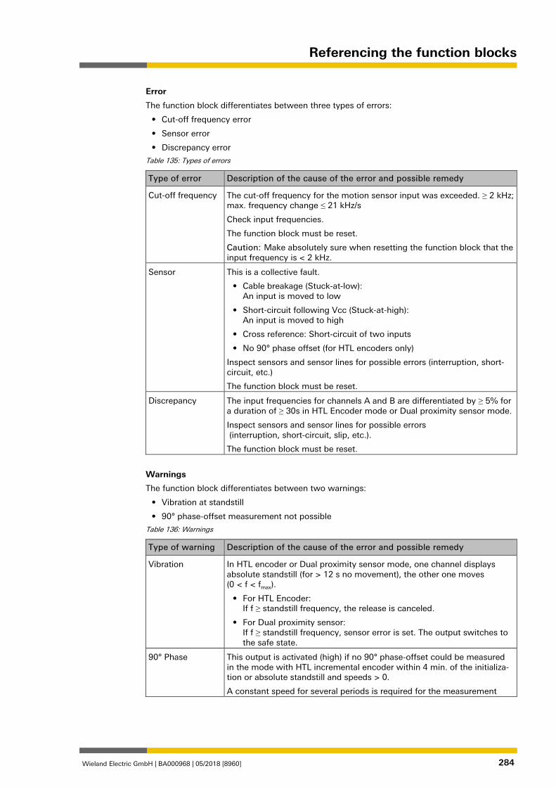
Referencing the function blocks
Wieland Electric GmbH | BA000968 | 05/2018 [8960] 284
Error
The function block differentiates between three types of errors:
• Cut-off frequency error
• Sensor error
• Discrepancy error
Table 135: Types of errors
Type of error Description of the cause of the error and possible remedy
Cut-off frequency The cut-off frequency for the motion sensor input was exceeded. ≥ 2 kHz; max. frequency change ≤ 21 kHz/s
Check input frequencies.
The function block must be reset.
Caution: Make absolutely sure when resetting the function block that the input frequency is < 2 kHz.
Sensor This is a collective fault.
• Cable breakage (Stuck-at-low): An input is moved to low
• Short-circuit following Vcc (Stuck-at-high): An input is moved to high
• Cross reference: Short-circuit of two inputs
• No 90° phase offset (for HTL encoders only)
Inspect sensors and sensor lines for possible errors (interruption, short-circuit, etc.)
The function block must be reset.
Discrepancy The input frequencies for channels A and B are differentiated by ≥ 5% for a duration of ≥ 30s in HTL Encoder mode or Dual proximity sensor mode.
Inspect sensors and sensor lines for possible errors (interruption, short-circuit, slip, etc.).
The function block must be reset.
Warnings
The function block differentiates between two warnings:
• Vibration at standstill
• 90° phase-offset measurement not possible
Table 136: Warnings
Type of warning Description of the cause of the error and possible remedy
Vibration In HTL encoder or Dual proximity sensor mode, one channel displays absolute standstill (for > 12 s no movement), the other one moves (0 < f < fmax).
• For HTL Encoder: If f ≥ standstill frequency, the release is canceled.
• For Dual proximity sensor: If f ≥ standstill frequency, sensor error is set. The output switches to the safe state.
90° Phase This output is activated (high) if no 90° phase-offset could be measured in the mode with HTL incremental encoder within 4 min. of the initializa-tion or absolute standstill and speeds > 0.
A constant speed for several periods is required for the measurement
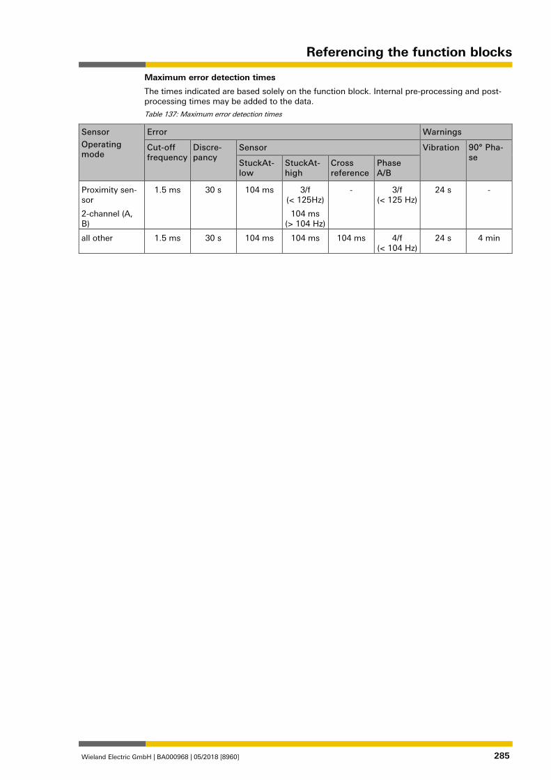
Referencing the function blocks
Wieland Electric GmbH | BA000968 | 05/2018 [8960] 285
Maximum error detection times
The times indicated are based solely on the function block. Internal pre-processing and post-processing times may be added to the data.
Table 137: Maximum error detection times
Sensor
Operating mode
Error Warnings
Cut-off frequency
Discre-pancy
Sensor Vibration 90° Pha-se
StuckAt-low
StuckAt-high
Cross reference
Phase A/B
Proximity sen-sor
2-channel (A, B)
1.5 ms
30 s
104 ms 3/f (< 125Hz)
104 ms (> 104 Hz)
- 3/f (< 125 Hz)
24 s -
all other 1.5 ms 30 s 104 ms 104 ms 104 ms 4/f (< 104 Hz)
24 s 4 min
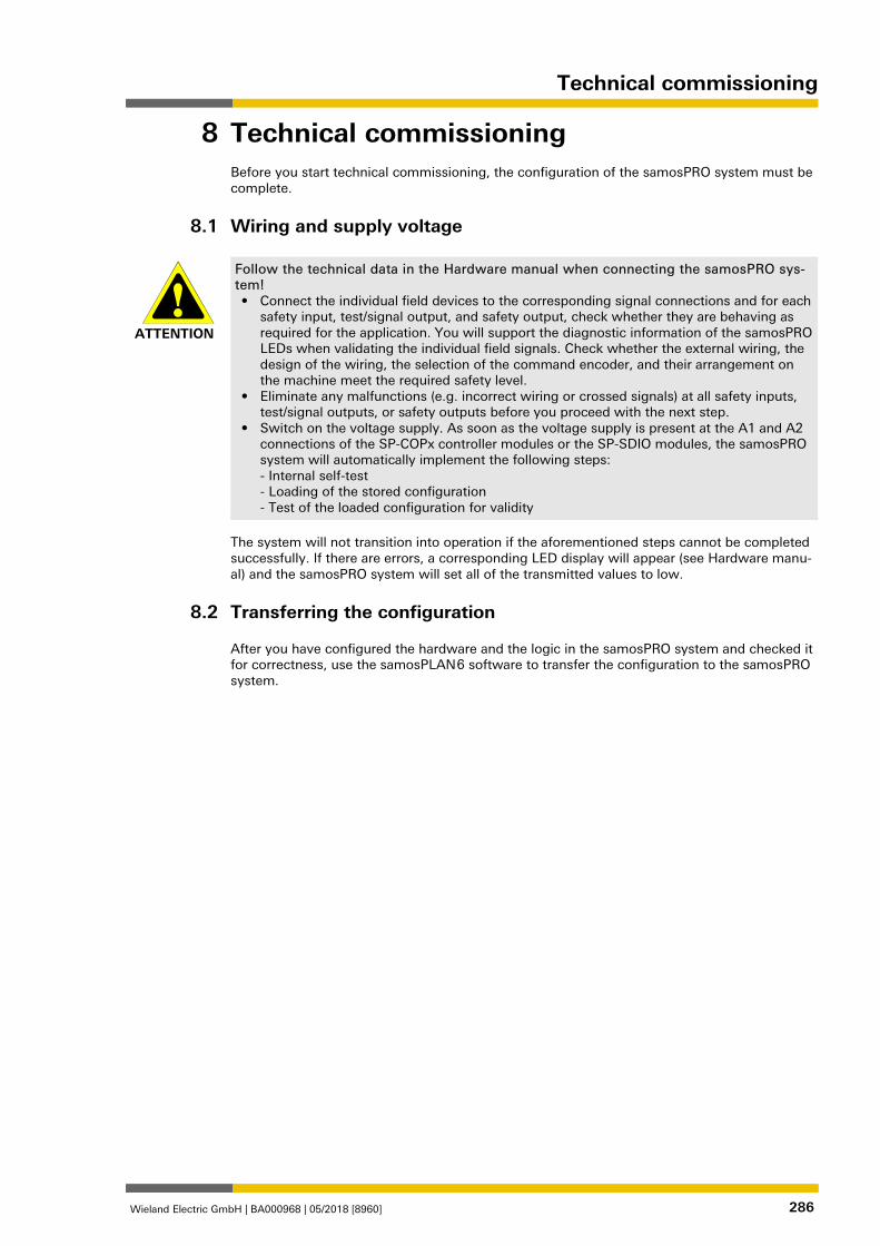
Technical commissioning
Wieland Electric GmbH | BA000968 | 05/2018 [8960] 286
Technical commissioning 840349963
Before you start technical commissioning, the configuration of the samosPRO system must be complete.
Wiring and supply voltage 841722251
ATTENTION
Follow the technical data in the Hardware manual when connecting the samosPRO sys-tem! • Connect the individual field devices to the corresponding signal connections and for each
safety input, test/signal output, and safety output, check whether they are behaving as required for the application. You will support the diagnostic information of the samosPRO LEDs when validating the individual field signals. Check whether the external wiring, the design of the wiring, the selection of the command encoder, and their arrangement on the machine meet the required safety level.
• Eliminate any malfunctions (e.g. incorrect wiring or crossed signals) at all safety inputs, test/signal outputs, or safety outputs before you proceed with the next step.
• Switch on the voltage supply. As soon as the voltage supply is present at the A1 and A2 connections of the SP-COPx controller modules or the SP-SDIO modules, the samosPRO system will automatically implement the following steps: - Internal self-test - Loading of the stored configuration - Test of the loaded configuration for validity
The system will not transition into operation if the aforementioned steps cannot be completed successfully. If there are errors, a corresponding LED display will appear (see Hardware manu-al) and the samosPRO system will set all of the transmitted values to low.
Transferring the configuration 841738763
After you have configured the hardware and the logic in the samosPRO system and checked it for correctness, use the samosPLAN 6 software to transfer the configuration to the samosPRO system.
8
8.1
8.2
Technical commissioning
Wieland Electric GmbH | BA000968 | 05/2018 [8960] 287
Technical check and commissioning 841742091
The machine or system that is being protected by a samosPROsafety controller may only be commissioned after a successful technical check of all of the safety functions. The technical check may only be completed by a qualified person.
The technical check comprises the following test points: Mark all the connection lines and plug connectors on the samosPRO system clearly to pre-
vent mixups. Because the samosPRO system has multiple connections with the same shape, make sure that connection lines that are disconnected are not connected back to the wrong connection.
Verify the configuration of the samosPRO system. Check the signal paths and the correct integration into higher-level controls. Check the correct data transmission from and to the samosPRO safety control. Check the logic program of the safety control. Fully document the configuration of the entire system, the individual devices, and the re-
sults of the safety check. Check the safety functions of the machine or system completely and make sure that the
safety functions are fully functioning.
8.3
Troubleshooting
Wieland Electric GmbH | BA000968 | 05/2018 [8960] 288
Troubleshooting 840351755
If an error occurs, you can find additional information here:
• Observing the device states of the system [ch. 6.9.1, p. 122] (list of LED error displays)
• Complete list of error messages [ch. 10.1, p. 289] (Error codes, error causes and trouble-shooting measures)
• Hardware manual
"Diagnostics" view
Error codes and error messages can also be displayed in the Diagnostics view if you have es-tablished a connection with the samosPRO system.
For more information as to how you can carry out diagnostics, please see the following: Using the monitoring functions [ch. 6.9, p. 122]
9
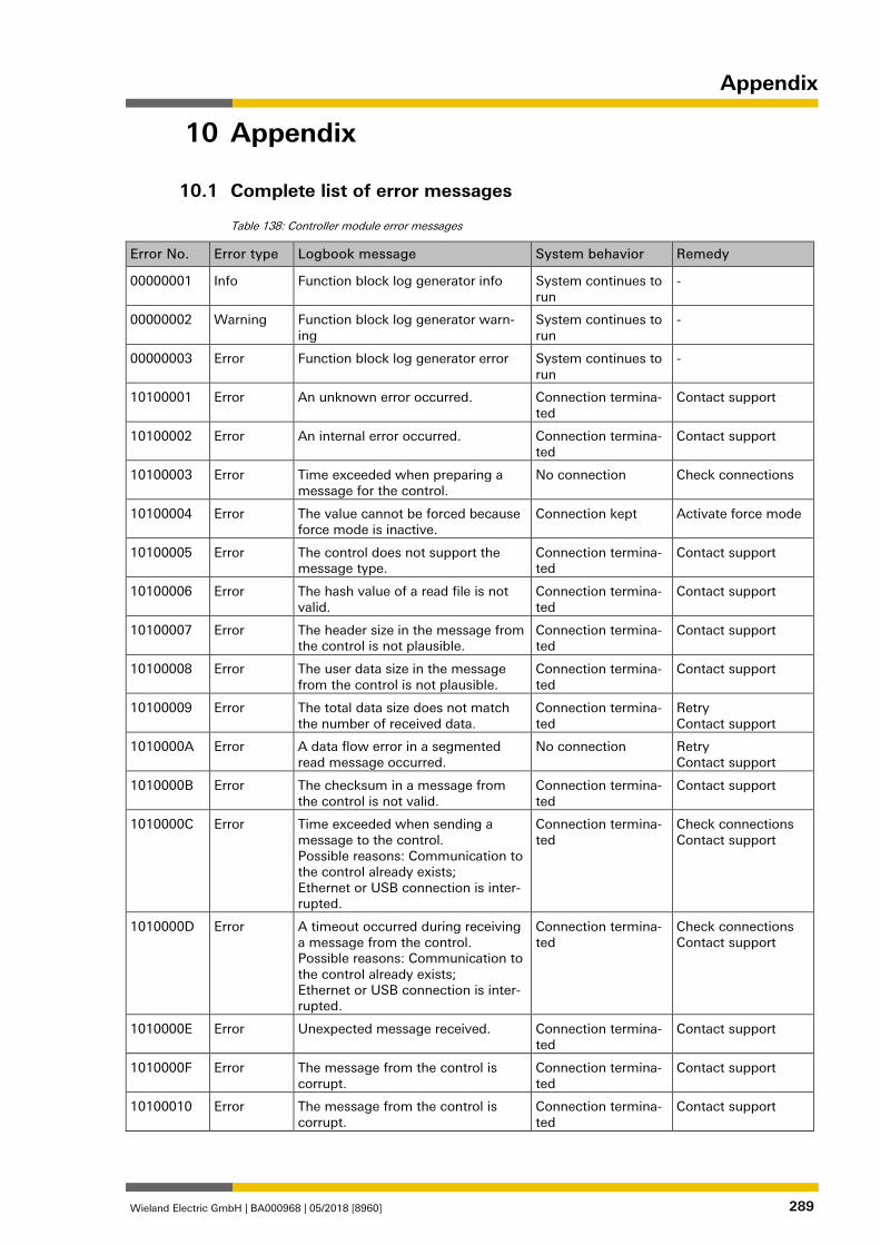
Appendix
Wieland Electric GmbH | BA000968 | 05/2018 [8960] 289
Appendix 903124235
Complete list of error messages 895000587
Table 138: Controller module error messages
Error No. Error type Logbook message System behavior Remedy
00000001 Info Function block log generator info System continues to run
-
00000002 Warning Function block log generator warn-ing
System continues to run
-
00000003 Error Function block log generator error System continues to run
-
10100001 Error An unknown error occurred. Connection termina-ted
Contact support
10100002 Error An internal error occurred. Connection termina-ted
Contact support
10100003 Error Time exceeded when preparing a message for the control.
No connection Check connections
10100004 Error The value cannot be forced because force mode is inactive.
Connection kept Activate force mode
10100005 Error The control does not support the message type.
Connection termina-ted
Contact support
10100006 Error The hash value of a read file is not valid.
Connection termina-ted
Contact support
10100007 Error The header size in the message from the control is not plausible.
Connection termina-ted
Contact support
10100008 Error The user data size in the message from the control is not plausible.
Connection termina-ted
Contact support
10100009 Error The total data size does not match the number of received data.
Connection termina-ted
Retry Contact support
1010000A Error A data flow error in a segmented read message occurred.
No connection Retry Contact support
1010000B Error The checksum in a message from the control is not valid.
Connection termina-ted
Contact support
1010000C Error Time exceeded when sending a message to the control. Possible reasons: Communication to the control already exists; Ethernet or USB connection is inter-rupted.
Connection termina-ted
Check connections Contact support
1010000D Error A timeout occurred during receiving a message from the control. Possible reasons: Communication to the control already exists; Ethernet or USB connection is inter-rupted.
Connection termina-ted
Check connections Contact support
1010000E Error Unexpected message received. Connection termina-ted
Contact support
1010000F Error The message from the control is corrupt.
Connection termina-ted
Contact support
10100010 Error The message from the control is corrupt.
Connection termina-ted
Contact support
10
10.1
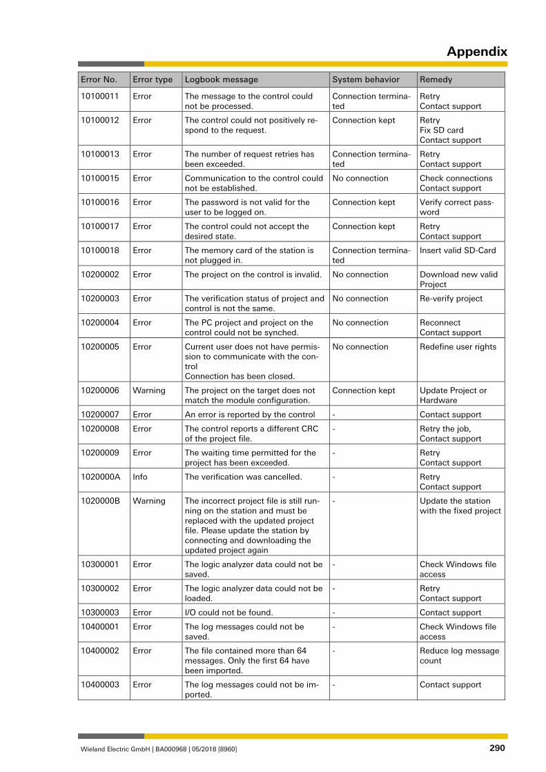
Appendix
Wieland Electric GmbH | BA000968 | 05/2018 [8960] 290
Error No. Error type Logbook message System behavior Remedy
10100011 Error The message to the control could not be processed.
Connection termina-ted
Retry Contact support
10100012 Error The control could not positively re-spond to the request.
Connection kept Retry Fix SD card Contact support
10100013 Error The number of request retries has been exceeded.
Connection termina-ted
Retry Contact support
10100015 Error Communication to the control could not be established.
No connection Check connections Contact support
10100016 Error The password is not valid for the user to be logged on.
Connection kept Verify correct pass-word
10100017 Error The control could not accept the desired state.
Connection kept Retry Contact support
10100018 Error The memory card of the station is not plugged in.
Connection termina-ted
Insert valid SD-Card
10200002 Error The project on the control is invalid. No connection Download new valid Project
10200003 Error The verification status of project and control is not the same.
No connection Re-verify project
10200004 Error The PC project and project on the control could not be synched.
No connection Reconnect Contact support
10200005 Error Current user does not have permis-sion to communicate with the con-trol Connection has been closed.
No connection Redefine user rights
10200006 Warning The project on the target does not match the module configuration.
Connection kept Update Project or Hardware
10200007 Error An error is reported by the control - Contact support
10200008 Error The control reports a different CRC of the project file.
- Retry the job, Contact support
10200009 Error The waiting time permitted for the project has been exceeded.
- Retry Contact support
1020000A Info The verification was cancelled. - Retry Contact support
1020000B Warning The incorrect project file is still run-ning on the station and must be replaced with the updated project file. Please update the station by connecting and downloading the updated project again
- Update the station with the fixed project
10300001 Error The logic analyzer data could not be saved.
- Check Windows file access
10300002 Error The logic analyzer data could not be loaded.
- Retry Contact support
10300003 Error I/O could not be found. - Contact support
10400001 Error The log messages could not be saved.
- Check Windows file access
10400002 Error The file contained more than 64 messages. Only the first 64 have been imported.
- Reduce log message count
10400003 Error The log messages could not be im-ported.
- Contact support
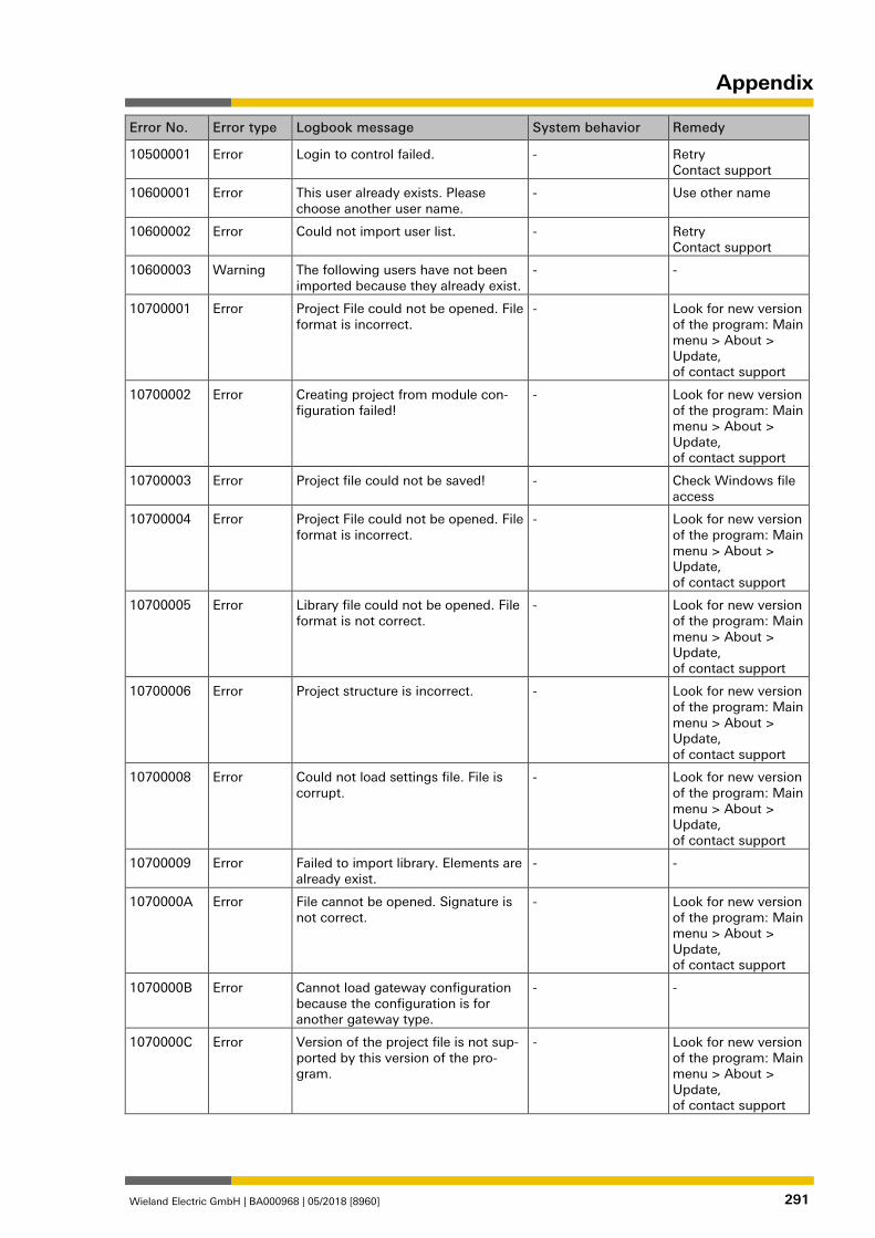
Appendix
Wieland Electric GmbH | BA000968 | 05/2018 [8960] 291
Error No. Error type Logbook message System behavior Remedy
10500001 Error Login to control failed. - Retry Contact support
10600001 Error This user already exists. Please choose another user name.
- Use other name
10600002 Error Could not import user list. - Retry Contact support
10600003 Warning The following users have not been imported because they already exist.
- -
10700001 Error Project File could not be opened. File format is incorrect.
- Look for new version of the program: Main menu > About > Update, of contact support
10700002 Error Creating project from module con-figuration failed!
- Look for new version of the program: Main menu > About > Update, of contact support
10700003 Error Project file could not be saved! - Check Windows file access
10700004 Error Project File could not be opened. File format is incorrect.
- Look for new version of the program: Main menu > About > Update, of contact support
10700005 Error Library file could not be opened. File format is not correct.
- Look for new version of the program: Main menu > About > Update, of contact support
10700006 Error Project structure is incorrect. - Look for new version of the program: Main menu > About > Update, of contact support
10700008 Error Could not load settings file. File is corrupt.
- Look for new version of the program: Main menu > About > Update, of contact support
10700009 Error Failed to import library. Elements are already exist.
- -
1070000A Error File cannot be opened. Signature is not correct.
- Look for new version of the program: Main menu > About > Update, of contact support
1070000B Error Cannot load gateway configuration because the configuration is for another gateway type.
- -
1070000C Error Version of the project file is not sup-ported by this version of the pro-gram.
- Look for new version of the program: Main menu > About > Update, of contact support
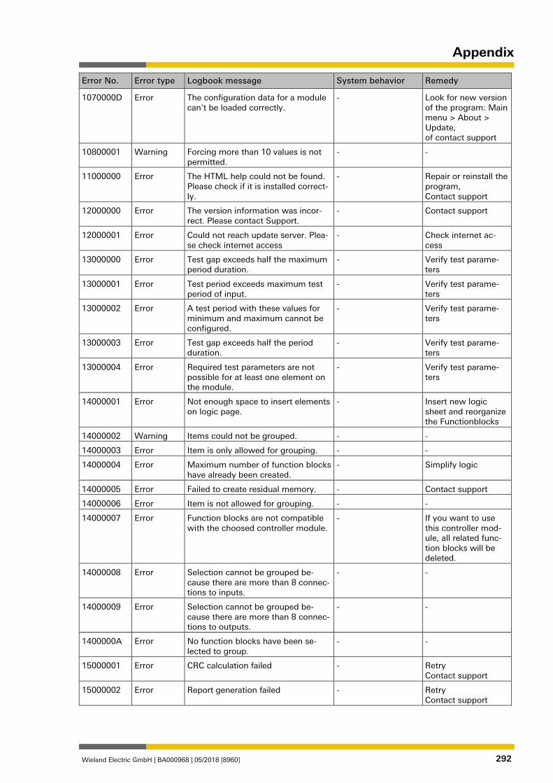
Appendix
Wieland Electric GmbH | BA000968 | 05/2018 [8960] 292
Error No. Error type Logbook message System behavior Remedy
1070000D Error The configuration data for a module can't be loaded correctly.
- Look for new version of the program: Main menu > About > Update, of contact support
10800001 Warning Forcing more than 10 values is not permitted.
- -
11000000 Error The HTML help could not be found. Please check if it is installed correct-ly.
- Repair or reinstall the program, Contact support
12000000 Error The version information was incor-rect. Please contact Support.
- Contact support
12000001 Error Could not reach update server. Plea-se check internet access
- Check internet ac-cess
13000000 Error Test gap exceeds half the maximum period duration.
- Verify test parame-ters
13000001 Error Test period exceeds maximum test period of input.
- Verify test parame-ters
13000002 Error A test period with these values for minimum and maximum cannot be configured.
- Verify test parame-ters
13000003 Error Test gap exceeds half the period duration.
- Verify test parame-ters
13000004 Error Required test parameters are not possible for at least one element on the module.
- Verify test parame-ters
14000001 Error Not enough space to insert elements on logic page.
- Insert new logic sheet and reorganize the Functionblocks
14000002 Warning Items could not be grouped. - -
14000003 Error Item is only allowed for grouping. - -
14000004 Error Maximum number of function blocks have already been created.
- Simplify logic
14000005 Error Failed to create residual memory. - Contact support
14000006 Error Item is not allowed for grouping. - -
14000007 Error Function blocks are not compatible with the choosed controller module.
- If you want to use this controller mod-ule, all related func-tion blocks will be deleted.
14000008 Error Selection cannot be grouped be-cause there are more than 8 connec-tions to inputs.
- -
14000009 Error Selection cannot be grouped be-cause there are more than 8 connec-tions to outputs.
- -
1400000A Error No function blocks have been se-lected to group.
- -
15000001 Error CRC calculation failed - Retry Contact support
15000002 Error Report generation failed - Retry Contact support
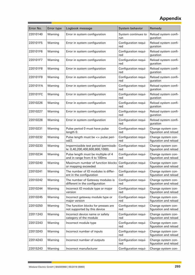
Appendix
Wieland Electric GmbH | BA000968 | 05/2018 [8960] 293
Error No. Error type Logbook message System behavior Remedy
22010140 Warning Error in system configuration System continues to run
Reload system confi-guration
220101F5 Warning Error in system configuration Configuration requi-red
Reload system confi-guration
220101F6 Warning Error in system configuration Configuration requi-red
Reload system confi-guration
220101F7 Warning Error in system configuration Configuration requi-red
Reload system confi-guration
220101F8 Warning Error in system configuration Configuration requi-red
Reload system confi-guration
220101F9 Warning Error in system configuration Configuration requi-red
Reload system confi-guration
220101FA Warning Error in system configuration Configuration requi-red
Reload system confi-guration
220101FC Warning Error in system configuration Configuration requi-red
Reload system confi-guration
22010226 Warning Error in system configuration Configuration requi-red
Reload system confi-guration
22010227 Warning Error in system configuration Configuration requi-red
Reload system confi-guration
22010228 Warning Error in system configuration Configuration requi-red
Reload system confi-guration
22010231 Warning Pulse period 0 must have pulse length 0.
Configuration requi-red
Change system con-figuration and reload
22010232 Warning Pulse length must be <= pulse peri-od/2.
Configuration requi-red
Change system con-figuration and reload
22010233 Warning Impermissible test period (permissib-le: 0,40,200,400,600,800,1000).
Configuration requi-red
Change system con-figuration and reload
22010234 Warning Pulse length must be multiple of 4 and in range from 4 to 100ms
Configuration requi-red
Change system con-figuration and reload
22010240 Warning Maximum number of function blocks or mapping exceeded
Configuration requi-red
Change system con-figuration and reload
22010241 Warning The number of IO modules is differ-ent in the configuration
Configuration requi-red
Change system con-figuration and reload
22010242 Warning The number of Gateway modules is different in the configuration
Configuration requi-red
Change system con-figuration and reload
22010244 Warning Incorrect IO module type or major version
Configuration requi-red
Change system con-figuration and reload
22010245 Warning Incorrect gateway module type or major version
Configuration requi-red
Change system con-figuration and reload
22010250 Warning The function blocks for presses are not supported by this device
Configuration requi-red
Change system con-figuration and reload
22011243 Warning Incorrect device name or safety category of the module
Configuration requi-red
Change system con-figuration and reload
22012243 Warning Incorrect module type Configuration requi-red
Change system con-figuration and reload
22013243 Warning Incorrect number of inputs Configuration requi-red
Change system con-figuration and reload
22014243 Warning Incorrect number of outputs Configuration requi-red
Change system con-figuration and reload
22015243 Warning Incorrect manufacturer Configuration requi- Change system con-
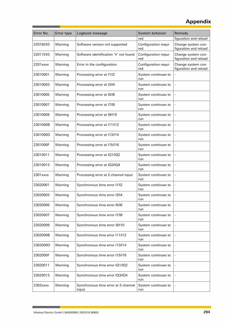
Appendix
Wieland Electric GmbH | BA000968 | 05/2018 [8960] 294
Error No. Error type Logbook message System behavior Remedy
red figuration and reload
22016243 Warning Software version not supported Configuration requi-red
Change system con-figuration and reload
22017243 Warning Software identification 'V' not found Configuration requi-red
Change system con-figuration and reload
2201xxxx Warning Error in the configuration Configuration requi-red
Change system con-figuration and reload
23010001 Warning Processing error at I1/I2 System continues to run
-
23010003 Warning Processing error at I3/I4 System continues to run
-
23010005 Warning Processing error at I5/I6 System continues to run
-
23010007 Warning Processing error at I7/I8 System continues to run
-
23010009 Warning Processing error at I9/I10 System continues to run
-
2301000B Warning Processing error at I11/I12 System continues to run
-
2301000D Warning Processing error at I13/I14 System continues to run
-
2301000F Warning Processing error at I15/I16 System continues to run
-
23010011 Warning Processing error at IQ1/IQ2 System continues to run
-
23010013 Warning Processing error at IQ3/IQ4 System continues to run
-
2301xxxx Warning Processing error at 2-channel input System continues to run
-
23020001 Warning Synchronous time error I1/I2 System continues to run
-
23020003 Warning Synchronous time error I3/I4 System continues to run
-
23020005 Warning Synchronous time error I5/I6 System continues to run
-
23020007 Warning Synchronous time error I7/I8 System continues to run
-
23020009 Warning Synchronous time error I9/I10 System continues to run
-
2302000B Warning Synchronous time error I11/I12 System continues to run
-
2302000D Warning Synchronous time error I13/I14 System continues to run
-
2302000F Warning Synchronous time error I15/I16 System continues to run
-
23020011 Warning Synchronous time error IQ1/IQ2 System continues to run
-
23020013 Warning Synchronous time error IQ3/IQ4 System continues to run
-
2302xxxx Warning Synchronous time error at 2-channel input
System continues to run
-
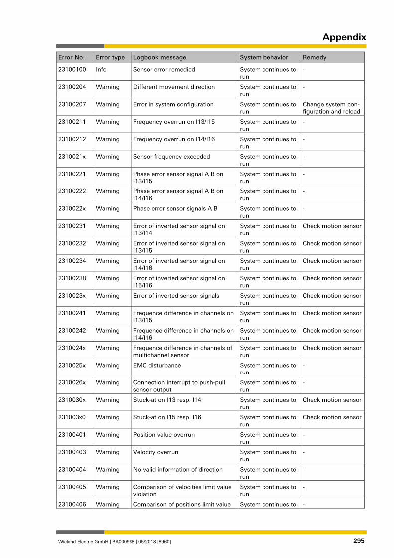
Appendix
Wieland Electric GmbH | BA000968 | 05/2018 [8960] 295
Error No. Error type Logbook message System behavior Remedy
23100100 Info Sensor error remedied System continues to run
-
23100204 Warning Different movement direction System continues to run
-
23100207 Warning Error in system configuration System continues to run
Change system con-figuration and reload
23100211 Warning Frequency overrun on I13/I15 System continues to run
-
23100212 Warning Frequency overrun on I14/I16 System continues to run
-
2310021x Warning Sensor frequency exceeded System continues to run
-
23100221 Warning Phase error sensor signal A B on I13/I15
System continues to run
-
23100222 Warning Phase error sensor signal A B on I14/I16
System continues to run
-
2310022x Warning Phase error sensor signals A B System continues to run
-
23100231 Warning Error of inverted sensor signal on I13/I14
System continues to run
Check motion sensor
23100232 Warning Error of inverted sensor signal on I13/I15
System continues to run
Check motion sensor
23100234 Warning Error of inverted sensor signal on I14/I16
System continues to run
Check motion sensor
23100238 Warning Error of inverted sensor signal on I15/I16
System continues to run
Check motion sensor
2310023x Warning Error of inverted sensor signals System continues to run
Check motion sensor
23100241 Warning Frequence difference in channels on I13/I15
System continues to run
Check motion sensor
23100242 Warning Frequence difference in channels on I14/I16
System continues to run
Check motion sensor
2310024x Warning Frequence difference in channels of multichannel sensor
System continues to run
Check motion sensor
2310025x Warning EMC disturbance System continues to run
-
2310026x Warning Connection interrupt to push-pull sensor output
System continues to run
-
2310030x Warning Stuck-at on I13 resp. I14 System continues to run
Check motion sensor
231003x0 Warning Stuck-at on I15 resp. I16 System continues to run
Check motion sensor
23100401 Warning Position value overrun System continues to run
-
23100403 Warning Velocity overrun System continues to run
-
23100404 Warning No valid information of direction System continues to run
-
23100405 Warning Comparison of velocities limit value violation
System continues to run
-
23100406 Warning Comparison of positions limit value System continues to -
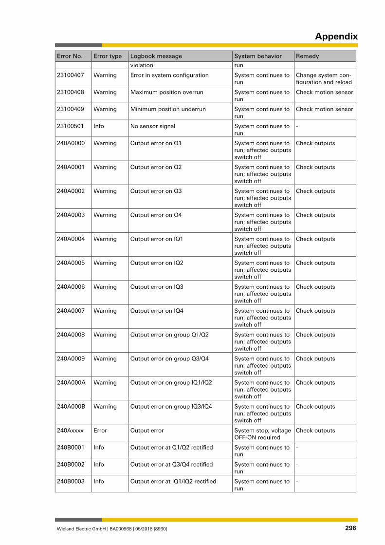
Appendix
Wieland Electric GmbH | BA000968 | 05/2018 [8960] 296
Error No. Error type Logbook message System behavior Remedy
violation run
23100407 Warning Error in system configuration System continues to run
Change system con-figuration and reload
23100408 Warning Maximum position overrun System continues to run
Check motion sensor
23100409 Warning Minimum position underrun System continues to run
Check motion sensor
23100501 Info No sensor signal System continues to run
-
240A0000 Warning Output error on Q1 System continues to run; affected outputs switch off
Check outputs
240A0001 Warning Output error on Q2 System continues to run; affected outputs switch off
Check outputs
240A0002 Warning Output error on Q3 System continues to run; affected outputs switch off
Check outputs
240A0003 Warning Output error on Q4 System continues to run; affected outputs switch off
Check outputs
240A0004 Warning Output error on IQ1 System continues to run; affected outputs switch off
Check outputs
240A0005 Warning Output error on IQ2 System continues to run; affected outputs switch off
Check outputs
240A0006 Warning Output error on IQ3 System continues to run; affected outputs switch off
Check outputs
240A0007 Warning Output error on IQ4 System continues to run; affected outputs switch off
Check outputs
240A0008 Warning Output error on group Q1/Q2 System continues to run; affected outputs switch off
Check outputs
240A0009 Warning Output error on group Q3/Q4 System continues to run; affected outputs switch off
Check outputs
240A000A Warning Output error on group IQ1/IQ2 System continues to run; affected outputs switch off
Check outputs
240A000B Warning Output error on group IQ3/IQ4 System continues to run; affected outputs switch off
Check outputs
240Axxxx Error Output error System stop; voltage OFF-ON required
Check outputs
240B0001 Info Output error at Q1/Q2 rectified System continues to run
-
240B0002 Info Output error at Q3/Q4 rectified System continues to run
-
240B0003 Info Output error at IQ1/IQ2 rectified System continues to run
-
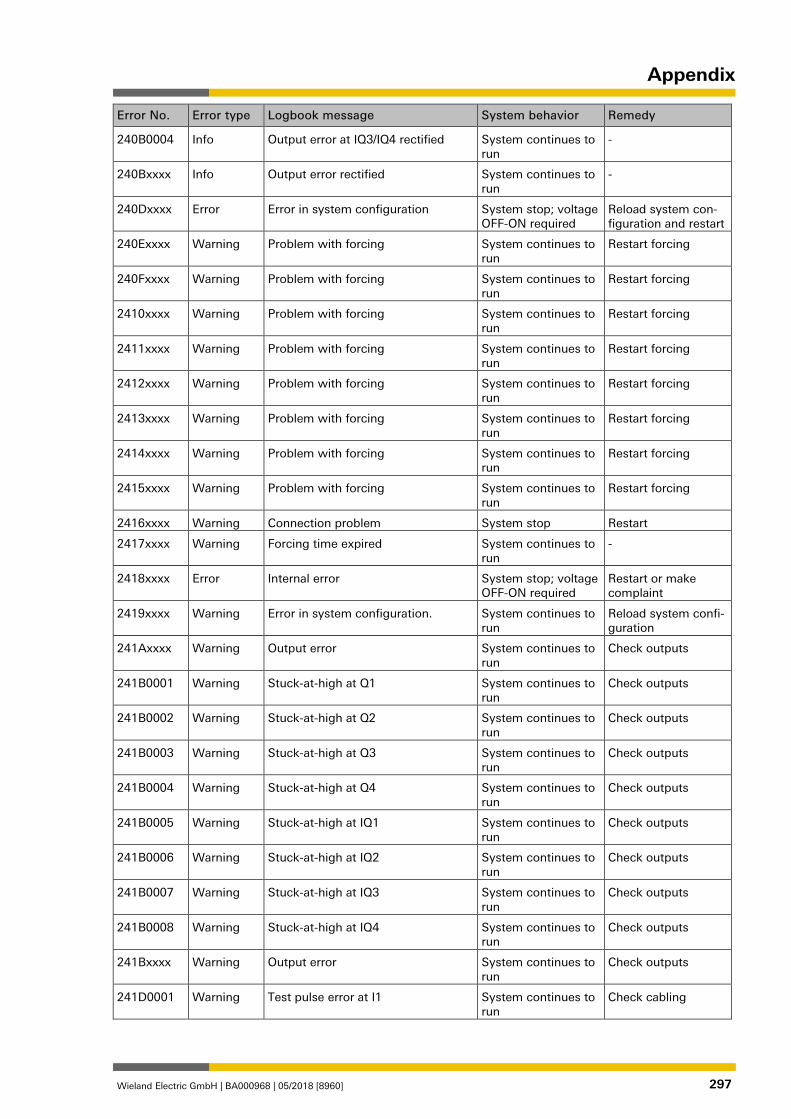
Appendix
Wieland Electric GmbH | BA000968 | 05/2018 [8960] 297
Error No. Error type Logbook message System behavior Remedy
240B0004 Info Output error at IQ3/IQ4 rectified System continues to run
-
240Bxxxx Info Output error rectified System continues to run
-
240Dxxxx Error Error in system configuration System stop; voltage OFF-ON required
Reload system con-figuration and restart
240Exxxx Warning Problem with forcing System continues to run
Restart forcing
240Fxxxx Warning Problem with forcing System continues to run
Restart forcing
2410xxxx Warning Problem with forcing System continues to run
Restart forcing
2411xxxx Warning Problem with forcing System continues to run
Restart forcing
2412xxxx Warning Problem with forcing System continues to run
Restart forcing
2413xxxx Warning Problem with forcing System continues to run
Restart forcing
2414xxxx Warning Problem with forcing System continues to run
Restart forcing
2415xxxx Warning Problem with forcing System continues to run
Restart forcing
2416xxxx Warning Connection problem System stop Restart
2417xxxx Warning Forcing time expired System continues to run
-
2418xxxx Error Internal error System stop; voltage OFF-ON required
Restart or make complaint
2419xxxx Warning Error in system configuration. System continues to run
Reload system confi-guration
241Axxxx Warning Output error System continues to run
Check outputs
241B0001 Warning Stuck-at-high at Q1 System continues to run
Check outputs
241B0002 Warning Stuck-at-high at Q2 System continues to run
Check outputs
241B0003 Warning Stuck-at-high at Q3 System continues to run
Check outputs
241B0004 Warning Stuck-at-high at Q4 System continues to run
Check outputs
241B0005 Warning Stuck-at-high at IQ1 System continues to run
Check outputs
241B0006 Warning Stuck-at-high at IQ2 System continues to run
Check outputs
241B0007 Warning Stuck-at-high at IQ3 System continues to run
Check outputs
241B0008 Warning Stuck-at-high at IQ4 System continues to run
Check outputs
241Bxxxx Warning Output error System continues to run
Check outputs
241D0001 Warning Test pulse error at I1 System continues to run
Check cabling
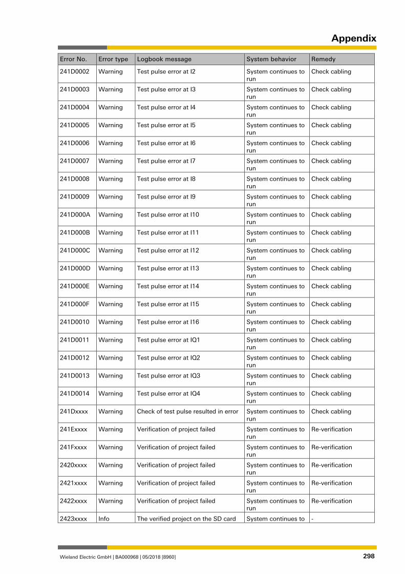
Appendix
Wieland Electric GmbH | BA000968 | 05/2018 [8960] 298
Error No. Error type Logbook message System behavior Remedy
241D0002 Warning Test pulse error at I2 System continues to run
Check cabling
241D0003 Warning Test pulse error at I3 System continues to run
Check cabling
241D0004 Warning Test pulse error at I4 System continues to run
Check cabling
241D0005 Warning Test pulse error at I5 System continues to run
Check cabling
241D0006 Warning Test pulse error at I6 System continues to run
Check cabling
241D0007 Warning Test pulse error at I7 System continues to run
Check cabling
241D0008 Warning Test pulse error at I8 System continues to run
Check cabling
241D0009 Warning Test pulse error at I9 System continues to run
Check cabling
241D000A Warning Test pulse error at I10 System continues to run
Check cabling
241D000B Warning Test pulse error at I11 System continues to run
Check cabling
241D000C Warning Test pulse error at I12 System continues to run
Check cabling
241D000D Warning Test pulse error at I13 System continues to run
Check cabling
241D000E Warning Test pulse error at I14 System continues to run
Check cabling
241D000F Warning Test pulse error at I15 System continues to run
Check cabling
241D0010 Warning Test pulse error at I16 System continues to run
Check cabling
241D0011 Warning Test pulse error at IQ1 System continues to run
Check cabling
241D0012 Warning Test pulse error at IQ2 System continues to run
Check cabling
241D0013 Warning Test pulse error at IQ3 System continues to run
Check cabling
241D0014 Warning Test pulse error at IQ4 System continues to run
Check cabling
241Dxxxx Warning Check of test pulse resulted in error System continues to run
Check cabling
241Exxxx Warning Verification of project failed System continues to run
Re-verification
241Fxxxx Warning Verification of project failed System continues to run
Re-verification
2420xxxx Warning Verification of project failed System continues to run
Re-verification
2421xxxx Warning Verification of project failed System continues to run
Re-verification
2422xxxx Warning Verification of project failed System continues to run
Re-verification
2423xxxx Info The verified project on the SD card System continues to -
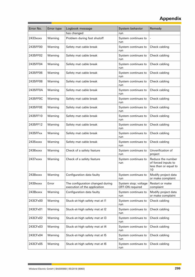
Appendix
Wieland Electric GmbH | BA000968 | 05/2018 [8960] 299
Error No. Error type Logbook message System behavior Remedy
has changed run
2433xxxx Warning Problem during fast shutoff System continues to run
-
2435FF00 Warning Safety mat cable break System continues to run
Check cabling
2435FF02 Warning Safety mat cable break System continues to run
Check cabling
2435FF04 Warning Safety mat cable break System continues to run
Check cabling
2435FF06 Warning Safety mat cable break System continues to run
Check cabling
2435FF08 Warning Safety mat cable break System continues to run
Check cabling
2435FF0A Warning Safety mat cable break System continues to run
Check cabling
2435FF0C Warning Safety mat cable break System continues to run
Check cabling
2435FF0E Warning Safety mat cable break System continues to run
Check cabling
2435FF10 Warning Safety mat cable break System continues to run
Check cabling
2435FF12 Warning Safety mat cable break System continues to run
Check cabling
2435FFxx Warning Safety mat cable break System continues to run
Check cabling
2435xxxx Warning Safety mat cable break System continues to run
Check cabling
2436xxxx Warning Check of a safety feature System continues to run
Unverification of project
2437xxxx Warning Check of a safety feature System continues to run
Reduce the number of forced inputs to less than or equal to 10
2438xxxx Warning Configuration data faulty System continues to run
Modify project data or make complaint
2439xxxx Error The configuration changed during execution of the application
System stop; voltage OFF-ON required
Restart or make complaint
243Bxxxx Warning Configuration data faulty System continues to run
Modify project data or make complaint
243CFx00 Warning Stuck-at-high safety mat at I1 System continues to run
Check cabling
243CFx01 Warning Stuck-at-high safety mat at I2 System continues to run
Check cabling
243CFx02 Warning Stuck-at-high safety mat at I3 System continues to run
Check cabling
243CFx03 Warning Stuck-at-high safety mat at I4 System continues to run
Check cabling
243CFx04 Warning Stuck-at-high safety mat at I5 System continues to run
Check cabling
243CFx05 Warning Stuck-at-high safety mat at I6 System continues to run
Check cabling
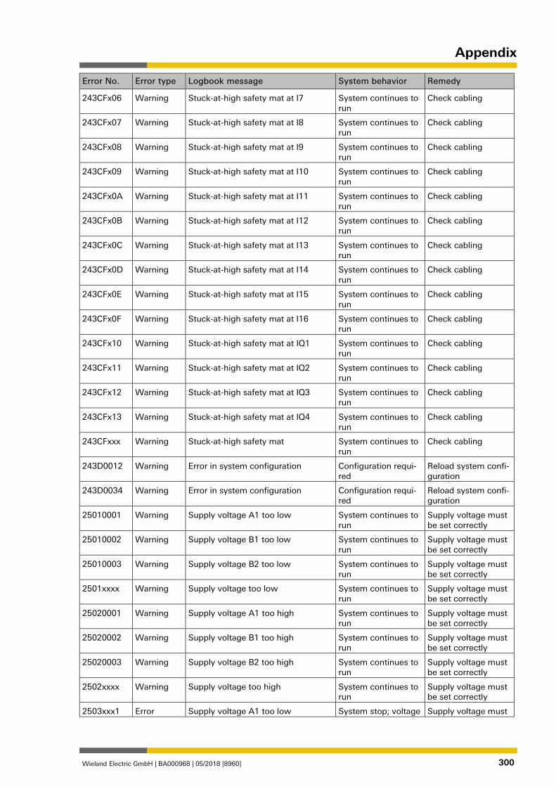
Appendix
Wieland Electric GmbH | BA000968 | 05/2018 [8960] 300
Error No. Error type Logbook message System behavior Remedy
243CFx06 Warning Stuck-at-high safety mat at I7 System continues to run
Check cabling
243CFx07 Warning Stuck-at-high safety mat at I8 System continues to run
Check cabling
243CFx08 Warning Stuck-at-high safety mat at I9 System continues to run
Check cabling
243CFx09 Warning Stuck-at-high safety mat at I10 System continues to run
Check cabling
243CFx0A Warning Stuck-at-high safety mat at I11 System continues to run
Check cabling
243CFx0B Warning Stuck-at-high safety mat at I12 System continues to run
Check cabling
243CFx0C Warning Stuck-at-high safety mat at I13 System continues to run
Check cabling
243CFx0D Warning Stuck-at-high safety mat at I14 System continues to run
Check cabling
243CFx0E Warning Stuck-at-high safety mat at I15 System continues to run
Check cabling
243CFx0F Warning Stuck-at-high safety mat at I16 System continues to run
Check cabling
243CFx10 Warning Stuck-at-high safety mat at IQ1 System continues to run
Check cabling
243CFx11 Warning Stuck-at-high safety mat at IQ2 System continues to run
Check cabling
243CFx12 Warning Stuck-at-high safety mat at IQ3 System continues to run
Check cabling
243CFx13 Warning Stuck-at-high safety mat at IQ4 System continues to run
Check cabling
243CFxxx Warning Stuck-at-high safety mat System continues to run
Check cabling
243D0012 Warning Error in system configuration Configuration requi-red
Reload system confi-guration
243D0034 Warning Error in system configuration Configuration requi-red
Reload system confi-guration
25010001 Warning Supply voltage A1 too low System continues to run
Supply voltage must be set correctly
25010002 Warning Supply voltage B1 too low System continues to run
Supply voltage must be set correctly
25010003 Warning Supply voltage B2 too low System continues to run
Supply voltage must be set correctly
2501xxxx Warning Supply voltage too low System continues to run
Supply voltage must be set correctly
25020001 Warning Supply voltage A1 too high System continues to run
Supply voltage must be set correctly
25020002 Warning Supply voltage B1 too high System continues to run
Supply voltage must be set correctly
25020003 Warning Supply voltage B2 too high System continues to run
Supply voltage must be set correctly
2502xxxx Warning Supply voltage too high System continues to run
Supply voltage must be set correctly
2503xxx1 Error Supply voltage A1 too low System stop; voltage Supply voltage must
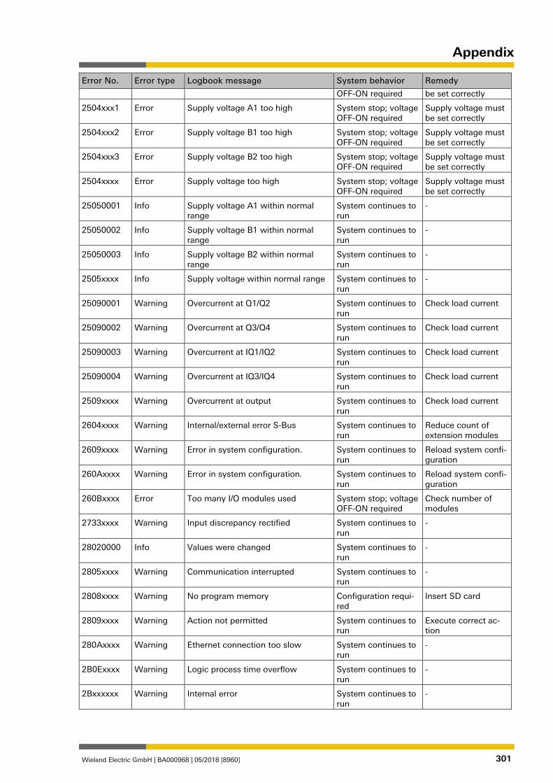
Appendix
Wieland Electric GmbH | BA000968 | 05/2018 [8960] 301
Error No. Error type Logbook message System behavior Remedy
OFF-ON required be set correctly
2504xxx1 Error Supply voltage A1 too high System stop; voltage OFF-ON required
Supply voltage must be set correctly
2504xxx2 Error Supply voltage B1 too high System stop; voltage OFF-ON required
Supply voltage must be set correctly
2504xxx3 Error Supply voltage B2 too high System stop; voltage OFF-ON required
Supply voltage must be set correctly
2504xxxx Error Supply voltage too high System stop; voltage OFF-ON required
Supply voltage must be set correctly
25050001 Info Supply voltage A1 within normal range
System continues to run
-
25050002 Info Supply voltage B1 within normal range
System continues to run
-
25050003 Info Supply voltage B2 within normal range
System continues to run
-
2505xxxx Info Supply voltage within normal range System continues to run
-
25090001 Warning Overcurrent at Q1/Q2 System continues to run
Check load current
25090002 Warning Overcurrent at Q3/Q4 System continues to run
Check load current
25090003 Warning Overcurrent at IQ1/IQ2 System continues to run
Check load current
25090004 Warning Overcurrent at IQ3/IQ4 System continues to run
Check load current
2509xxxx Warning Overcurrent at output System continues to run
Check load current
2604xxxx Warning Internal/external error S-Bus System continues to run
Reduce count of extension modules
2609xxxx Warning Error in system configuration. System continues to run
Reload system confi-guration
260Axxxx Warning Error in system configuration. System continues to run
Reload system confi-guration
260Bxxxx Error Too many I/O modules used System stop; voltage OFF-ON required
Check number of modules
2733xxxx Warning Input discrepancy rectified System continues to run
-
28020000 Info Values were changed System continues to run
-
2805xxxx Warning Communication interrupted System continues to run
-
2808xxxx Warning No program memory Configuration requi-red
Insert SD card
2809xxxx Warning Action not permitted System continues to run
Execute correct ac-tion
280Axxxx Warning Ethernet connection too slow System continues to run
-
2B0Exxxx Warning Logic process time overflow System continues to run
-
2Bxxxxxx Warning Internal error System continues to run
-
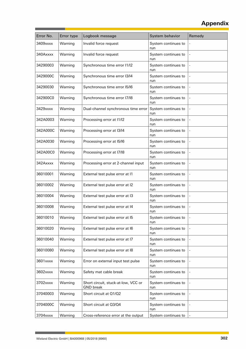
Appendix
Wieland Electric GmbH | BA000968 | 05/2018 [8960] 302
Error No. Error type Logbook message System behavior Remedy
3409xxxx Warning Invalid force request System continues to run
-
340Axxxx Warning Invalid force request System continues to run
-
34290003 Warning Synchronous time error I1/I2 System continues to run
-
3429000C Warning Synchronous time error I3/I4 System continues to run
-
34290030 Warning Synchronous time error I5/I6 System continues to run
-
342900C0 Warning Synchronous time error I7/I8 System continues to run
-
3429xxxx Warning Dual-channel synchronous time error System continues to run
-
342A0003 Warning Processing error at I1/I2 System continues to run
-
342A000C Warning Processing error at I3/I4 System continues to run
-
342A0030 Warning Processing error at I5/I6 System continues to run
-
342A00C0 Warning Processing error at I7/I8 System continues to run
-
342Axxxx Warning Processing error at 2-channel input System continues to run
-
36010001 Warning External test pulse error at I1 System continues to run
-
36010002 Warning External test pulse error at I2 System continues to run
-
36010004 Warning External test pulse error at I3 System continues to run
-
36010008 Warning External test pulse error at I4 System continues to run
-
36010010 Warning External test pulse error at I5 System continues to run
-
36010020 Warning External test pulse error at I6 System continues to run
-
36010040 Warning External test pulse error at I7 System continues to run
-
36010080 Warning External test pulse error at I8 System continues to run
-
3601xxxx Warning Error on external input test pulse System continues to run
-
3602xxxx Warning Safety mat cable break System continues to run
-
3702xxxx Warning Short circuit, stuck-at-low, VCC or GND break
System continues to run
-
37040003 Warning Short circuit at Q1/Q2 System continues to run
-
3704000C Warning Short circuit at Q3/Q4 System continues to run
-
3704xxxx Warning Cross-reference error at the output System continues to -
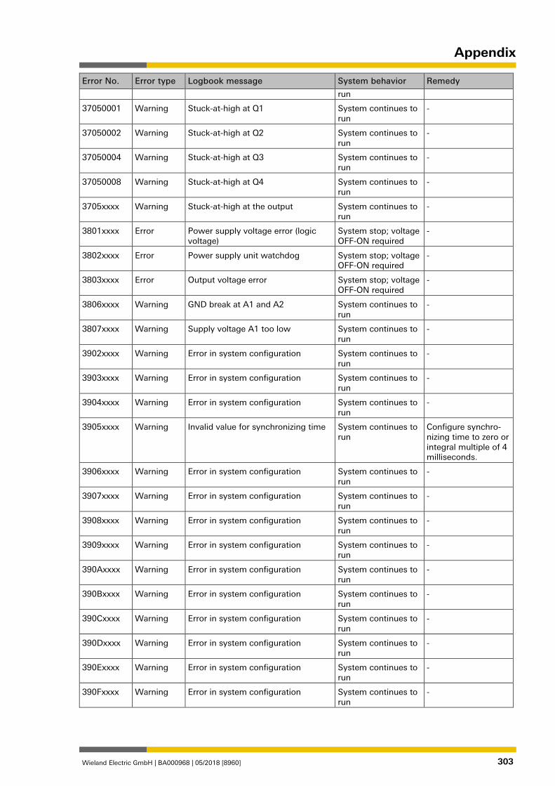
Appendix
Wieland Electric GmbH | BA000968 | 05/2018 [8960] 303
Error No. Error type Logbook message System behavior Remedy
run
37050001 Warning Stuck-at-high at Q1 System continues to run
-
37050002 Warning Stuck-at-high at Q2 System continues to run
-
37050004 Warning Stuck-at-high at Q3 System continues to run
-
37050008 Warning Stuck-at-high at Q4 System continues to run
-
3705xxxx Warning Stuck-at-high at the output System continues to run
-
3801xxxx Error Power supply voltage error (logic voltage)
System stop; voltage OFF-ON required
-
3802xxxx Error Power supply unit watchdog System stop; voltage OFF-ON required
-
3803xxxx Error Output voltage error System stop; voltage OFF-ON required
-
3806xxxx Warning GND break at A1 and A2 System continues to run
-
3807xxxx Warning Supply voltage A1 too low System continues to run
-
3902xxxx Warning Error in system configuration System continues to run
-
3903xxxx Warning Error in system configuration System continues to run
-
3904xxxx Warning Error in system configuration System continues to run
-
3905xxxx Warning Invalid value for synchronizing time System continues to run
Configure synchro-nizing time to zero or integral multiple of 4 milliseconds.
3906xxxx Warning Error in system configuration System continues to run
-
3907xxxx Warning Error in system configuration System continues to run
-
3908xxxx Warning Error in system configuration System continues to run
-
3909xxxx Warning Error in system configuration System continues to run
-
390Axxxx Warning Error in system configuration System continues to run
-
390Bxxxx Warning Error in system configuration System continues to run
-
390Cxxxx Warning Error in system configuration System continues to run
-
390Dxxxx Warning Error in system configuration System continues to run
-
390Exxxx Warning Error in system configuration System continues to run
-
390Fxxxx Warning Error in system configuration System continues to run
-
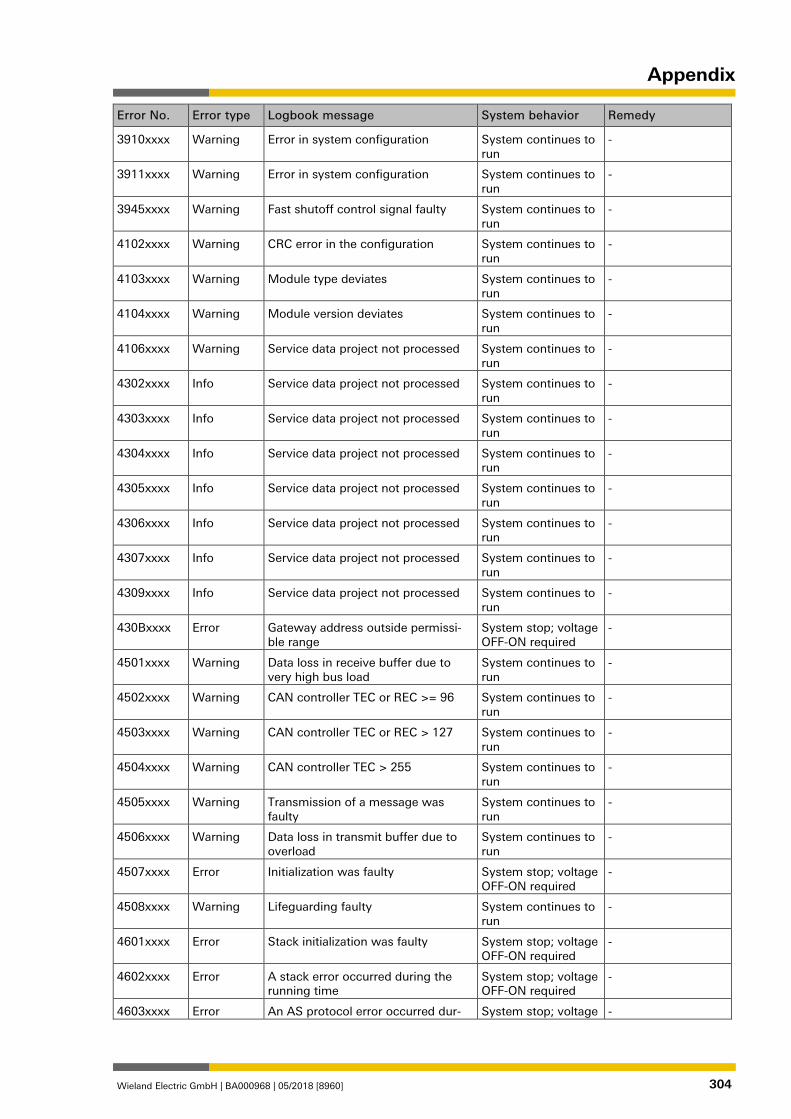
Appendix
Wieland Electric GmbH | BA000968 | 05/2018 [8960] 304
Error No. Error type Logbook message System behavior Remedy
3910xxxx Warning Error in system configuration System continues to run
-
3911xxxx Warning Error in system configuration System continues to run
-
3945xxxx Warning Fast shutoff control signal faulty System continues to run
-
4102xxxx Warning CRC error in the configuration System continues to run
-
4103xxxx Warning Module type deviates System continues to run
-
4104xxxx Warning Module version deviates System continues to run
-
4106xxxx Warning Service data project not processed System continues to run
-
4302xxxx Info Service data project not processed System continues to run
-
4303xxxx Info Service data project not processed System continues to run
-
4304xxxx Info Service data project not processed System continues to run
-
4305xxxx Info Service data project not processed System continues to run
-
4306xxxx Info Service data project not processed System continues to run
-
4307xxxx Info Service data project not processed System continues to run
-
4309xxxx Info Service data project not processed System continues to run
-
430Bxxxx Error Gateway address outside permissi-ble range
System stop; voltage OFF-ON required
-
4501xxxx Warning Data loss in receive buffer due to very high bus load
System continues to run
-
4502xxxx Warning CAN controller TEC or REC >= 96 System continues to run
-
4503xxxx Warning CAN controller TEC or REC > 127 System continues to run
-
4504xxxx Warning CAN controller TEC > 255 System continues to run
-
4505xxxx Warning Transmission of a message was faulty
System continues to run
-
4506xxxx Warning Data loss in transmit buffer due to overload
System continues to run
-
4507xxxx Error Initialization was faulty System stop; voltage OFF-ON required
-
4508xxxx Warning Lifeguarding faulty System continues to run
-
4601xxxx Error Stack initialization was faulty System stop; voltage OFF-ON required
-
4602xxxx Error A stack error occurred during the running time
System stop; voltage OFF-ON required
-
4603xxxx Error An AS protocol error occurred dur- System stop; voltage -
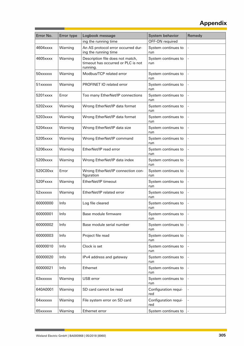
Appendix
Wieland Electric GmbH | BA000968 | 05/2018 [8960] 305
Error No. Error type Logbook message System behavior Remedy
ing the running time OFF-ON required
4604xxxx Warning An AS protocol error occurred dur-ing the running time
System continues to run
-
4605xxxx Warning Description file does not match, timeout has occurred or PLC is not running.
System continues to run
-
50xxxxxx Warning Modbus/TCP related error System continues to run
-
51xxxxxx Warning PROFINET IO related error System continues to run
-
5201xxxx Error Too many EtherNet/IP connections System continues to run
-
5202xxxx Warning Wrong EtherNet/IP data format System continues to run
-
5203xxxx Warning Wrong EtherNet/IP data format System continues to run
-
5204xxxx Warning Wrong EtherNet/IP data size System continues to run
-
5205xxxx Warning Wrong EtherNet/IP command System continues to run
-
5206xxxx Warning EtherNet/IP read error System continues to run
-
5209xxxx Warning Wrong EtherNet/IP data index System continues to run
-
520C00xx Error Wrong EtherNet/IP connection con-figuration
System continues to run
-
520Fxxxx Warning EtherNet/IP timeout System continues to run
-
52xxxxxx Warning EtherNet/IP related error System continues to run
-
60000000 Info Log file cleared System continues to run
-
60000001 Info Base module firmware System continues to run
-
60000002 Info Base module serial number System continues to run
-
60000003 Info Project file read System continues to run
-
60000010 Info Clock is set System continues to run
-
60000020 Info IPv4 address and gateway System continues to run
-
60000021 Info Ethernet System continues to run
-
63xxxxxx Warning USB error System continues to run
-
640A0001 Warning SD card cannot be read Configuration requi-red
-
64xxxxxx Warning File system error on SD card Configuration requi-red
-
65xxxxxx Warning Ethernet error System continues to -
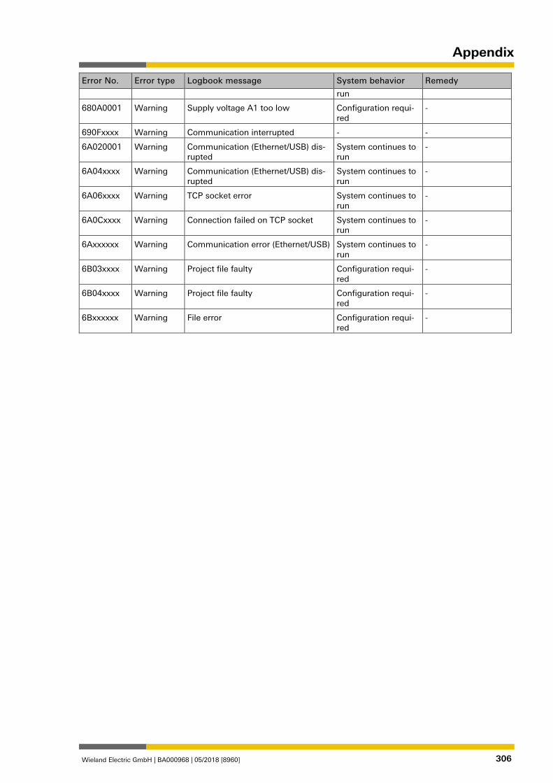
Appendix
Wieland Electric GmbH | BA000968 | 05/2018 [8960] 306
Error No. Error type Logbook message System behavior Remedy
run
680A0001 Warning Supply voltage A1 too low Configuration requi-red
-
690Fxxxx Warning Communication interrupted - -
6A020001 Warning Communication (Ethernet/USB) dis-rupted
System continues to run
-
6A04xxxx Warning Communication (Ethernet/USB) dis-rupted
System continues to run
-
6A06xxxx Warning TCP socket error System continues to run
-
6A0Cxxxx Warning Connection failed on TCP socket System continues to run
-
6Axxxxxx Warning Communication error (Ethernet/USB) System continues to run
-
6B03xxxx Warning Project file faulty Configuration requi-red
-
6B04xxxx Warning Project file faulty Configuration requi-red
-
6Bxxxxxx Warning File error Configuration requi-red
-

1291322251
Wieland Electric GmbH Brennerstraße 10 - 14 D-96052 Bamberg
Tel.: +49 (951) 9324-0 Fax: +49 (951) 9324-198 www.wieland-electric.com [email protected]