Embed Size (px)
Citation preview

SERVICE MANUAL
2005.04Ver. 1.0
FIELD SERVICE
NC-502
bizhub_162_210_FS.book 1 ページ 2005年4月18日 月曜日 午前10時5分

bizhub_162_210_FS.book 2 ページ 2005年4月18日 月曜日 午前10時5分
bizhub_162_210_FS.book 1 ページ 2005年4月18日 月曜日 午前10時5分
After publication of this service manual, the parts and mechanism may be subject to change forimprovement of their performance. Therefore, the descriptions given in this service manual may not coincide with the actual machine.
When any change has been made to the descriptions in the service manual, a revised version will beissued with a revision mark added as required.
Revision mark:• To indicate clearly a section revised, show to the left of the revised section.
A number within represents the number of times the revision has been made.
• To indicate clearly a section revised, show in the lower outside section of the correspond-ing page. A number within represents the number of times the revision has been made.
NOTERevision marks shown in a page are restricted only to the latest ones with the old ones deleted.
• When a page revised in Ver. 2.0 has been changed in Ver. 3.0: The revision marks for Ver. 3.0 only are shown with those for Ver. 2.0 deleted.
• When a page revised in Ver. 2.0 has not been changed in Ver. 3.0: The revision marks for Ver. 2.0 are left as they are.
11
1
1
2005/04 1.0 — Issue of the first edition
Date Service manual Ver. Revision mark Descriptions of revision

bizhub_162_210_FS.book 2 ページ 2005年4月18日 月曜日 午前10時5分
NC
-50
2G
en
era
lM
ain
ten
an
ce
Ad
justm
en
t /
Se
ttin
gT
rou
ble
sh
oo
tin
g
Field Service Ver. 1.0 Apr. 2005
bizhub_162_210_FS.book i ページ 2005年4月18日 月曜日 午前10時5分
CONTENTS
General1. Product specifications ............................................................................................. 1
2. Data Flow Diagram.................................................................................................. 1
2.1 Data Flow Diagram for Network GDI Printing ....................................................... 1
2.2 Electrical Components.......................................................................................... 2
2.2.1 Network Interface Card ................................................................................. 2
2.2.2 LED status display list ................................................................................... 3
Maintenance3. Firmware upgrade ................................................................................................... 5
3.1 Firmware rewriting ................................................................................................ 5
3.1.1 Updating method........................................................................................... 5
4. Other ....................................................................................................................... 8
4.1 Disassembly/Adjustment prohibited items ............................................................ 8
4.2 Disassembly/Assembly procedure........................................................................ 9
4.2.1 Network Interface Card ................................................................................. 9
Adjustment/Setting5. How to use the adjustment section ....................................................................... 11
6. Utility Mode ........................................................................................................... 12
6.1 Utility Mode function tree .................................................................................... 12
6.2 Utility Mode function setting procedure............................................................... 14
6.2.1 Procedure ................................................................................................... 14
6.2.2 Exiting ......................................................................................................... 14
6.2.3 Changing the setting value in Utility Mode functions................................... 14
6.3 Setting in the Utility Mode................................................................................... 14
6.3.1 Network setting ........................................................................................... 14
Troubleshooting7. Troubleshooting ..................................................................................................... 17
7.1 Troubleshooting Procedure Overview................................................................. 17
7.2 Troubleshooting Procedure Chart ....................................................................... 17
7.3 Action Taken if Network Print Cannot be Done................................................... 18
i
NC
-50
2G
en
era
lM
ain
ten
an
ce
Ad
justm
en
t /
Se
ttin
gT
rou
ble
sh
oo
tin
gField Service Ver. 1.0 Apr. 2005
bizhub_162_210_FS.book ii ページ 2005年4月18日 月曜日 午前10時5分
Blank page
ii
Field Service Ver. 1.0 Apr. 2005 1. Product specifications
NC
-50
2G
en
era
l
bizhub_162_210_FS.book 1 ページ 2005年4月18日 月曜日 午前10時5分
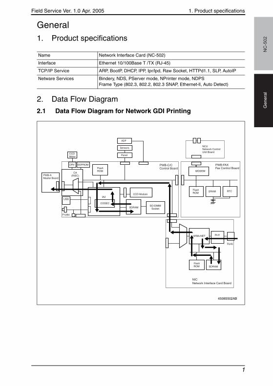
General1. Product specifications
2. Data Flow Diagram
2.1 Data Flow Diagram for Network GDI Printing
Name Network Interface Card (NC-502)
Interface Ethernet 10/100Base T /TX (RJ-45)
TCP/IP Service ARP, BootP, DHCP, IPP, Ipr/lpd, Raw Socket, HTTPd1.1, SLP, AutoIP
Netware Services Bindery, NDS, PServer mode, NPrinter mode, NDPSFrame Type (802.3, 802.2, 802.3 SNAP, Ethernet-ll, Auto Detect)
4508S502AB
CCDMotor
DRV EEPROM
CA(RISC)PWB-A
Master Board
USB
P1284
FlashROM
FlashROM
ADF
Sensors
Panel
IA2
CODEC
CCD Module
SDRAMSO-DIMM
Socket
SDRAM
PHYARM+NET
SRAM RTC
MODEM
NCU
RJ45
Network ControlUnit Board
NICNetwork Interface Card Board
PWB-C/CControl Board
FlashROM
PWB-FAXFax Control Board
1
2. Data Flow Diagram Field Service Ver. 1.0 Apr. 2005N
C-5
02
Ge
ne
ral
bizhub_162_210_FS.book 2 ページ 2005年4月18日 月曜日 午前10時5分
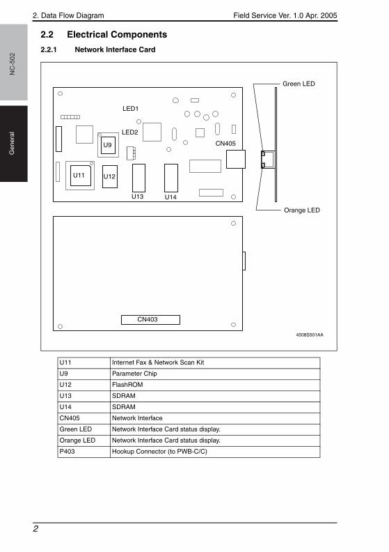
2.2 Electrical Components
2.2.1 Network Interface Card
U11 Internet Fax & Network Scan Kit
U9 Parameter Chip
U12 FlashROM
U13 SDRAM
U14 SDRAM
CN405 Network Interface
Green LED Network Interface Card status display.
Orange LED Network Interface Card status display.
P403 Hookup Connector (to PWB-C/C)
4508S501AA
U11
LED1
LED2
CN403
CN405
Orange LED
Green LED
U12
U9
U13 U14
2

Field Service Ver. 1.0 Apr. 2005 2. Data Flow Diagram
NC
-50
2G
en
era
l
bizhub_162_210_FS.book 3 ページ 2005年4月18日 月曜日 午前10時5分
2.2.2 LED status display list
LEDs Status
Green LED (Green) ON
This is lit when the network cable is connected correctly. If this LED is not lit, check the connection again, even if the copier appears to be connected correctly. If this LED is not lit when both ends are con-nected correctly, the network cable may be damaged.
Orange LED (Orange) ON This LED blinks when data is being transfered.
3

2. Data Flow Diagram Field Service Ver. 1.0 Apr. 2005N
C-5
02
Ge
ne
ral
bizhub_162_210_FS.book 4 ページ 2005年4月18日 月曜日 午前10時5分
Blank page
4
Field Service Ver. 1.0 Apr. 2005 3. Firmware upgrade
NC
-50
2M
ain
ten
an
ce
bizhub_162_210_FS.book 5 ページ 2005年4月18日 月曜日 午前10時5分
Maintenance3. Firmware upgrade
3.1 Firmware rewriting
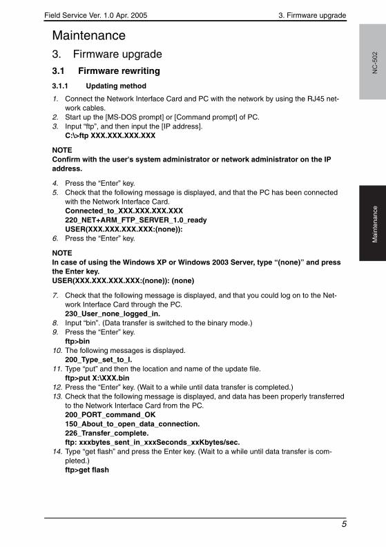
3.1.1 Updating method
1. Connect the Network Interface Card and PC with the network by using the RJ45 net-work cables.
2. Start up the [MS-DOS prompt] or [Command prompt] of PC.3. Input “ftp”, and then input the [IP address].
C:\>ftp XXX.XXX.XXX.XXX
NOTEConfirm with the user's system administrator or network administrator on the IP address.
4. Press the “Enter” key.5. Check that the following message is displayed, and that the PC has been connected
with the Network Interface Card. Connected_to_XXX.XXX.XXX.XXX220_NET+ARM_FTP_SERVER_1.0_readyUSER(XXX.XXX.XXX.XXX:(none)):
6. Press the “Enter” key.
NOTEIn case of using the Windows XP or Windows 2003 Server, type “(none)” and press the Enter key.USER(XXX.XXX.XXX.XXX:(none)): (none)
7. Check that the following message is displayed, and that you could log on to the Net-work Interface Card through the PC.230_User_none_logged_in.
8. Input “bin”. (Data transfer is switched to the binary mode.)9. Press the “Enter” key.
ftp>bin10. The following messages is displayed.
200_Type_set_to_I.11. Type “put” and then the location and name of the update file.
ftp>put X:\XXX.bin12. Press the “Enter” key. (Wait to a while until data transfer is completed.)13. Check that the following message is displayed, and data has been properly transferred
to the Network Interface Card from the PC.200_PORT_command_OK150_About_to_open_data_connection.226_Transfer_complete.ftp: xxxbytes_sent_in_xxxSeconds_xxKbytes/sec.
14. Type “get flash” and press the Enter key. (Wait to a while until data transfer is com-pleted.)ftp>get flash
5
3. Firmware upgrade Field Service Ver. 1.0 Apr. 2005N
C-5
02
Ma
inte
na
nce
bizhub_162_210_FS.book 6 ページ 2005年4月18日 月曜日 午前10時5分
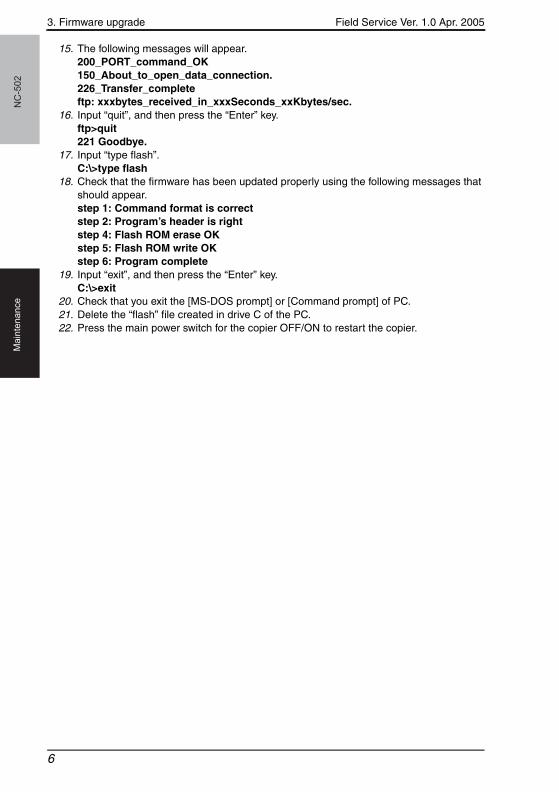
15. The following messages will appear.200_PORT_command_OK150_About_to_open_data_connection.226_Transfer_completeftp: xxxbytes_received_in_xxxSeconds_xxKbytes/sec.
16. Input “quit”, and then press the “Enter” key.ftp>quit221 Goodbye.
17. Input “type flash”.C:\>type flash
18. Check that the firmware has been updated properly using the following messages that should appear.step 1: Command format is correctstep 2: Program’s header is rightstep 4: Flash ROM erase OKstep 5: Flash ROM write OKstep 6: Program complete
19. Input “exit”, and then press the “Enter” key.C:\>exit
20. Check that you exit the [MS-DOS prompt] or [Command prompt] of PC.21. Delete the “flash” file created in drive C of the PC.22. Press the main power switch for the copier OFF/ON to restart the copier.
6
Field Service Ver. 1.0 Apr. 2005 3. Firmware upgrade
NC
-50
2M
ain
ten
an
ce
bizhub_162_210_FS.book 7 ページ 2005年4月18日 月曜日 午前10時5分
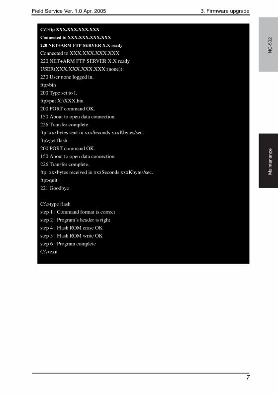
C:\>ftp XXX.XXX.XXX.XXX
Connected to XXX.XXX.XXX.XXX
220 NET+ARM FTP SERVER X.X ready
Connected to XXX.XXX.XXX.XXX
220 NET+ARM FTP SERVER X.X ready
USER(XXX.XXX.XXX.XXX:(none)):
230 User none logged in.
ftp>bin
200 Type set to I.
ftp>put X:\XXX.bin
200 PORT command OK.
150 About to open data connection.
226 Transfer complete
ftp: xxxbytes sent in xxxSeconds xxxKbytes/sec.
ftp>get flash
200 PORT command OK.
150 About to open data connection.
226 Transfer complete.
ftp: xxxbytes received in xxxSeconds xxxKbytes/sec.
ftp>quit
221 Goodbye
C:\>type flash
step 1 : Command format is correct
step 2 : Program’s header is right
step 4 : Flash ROM erase OK
step 5 : Flash ROM write OK
step 6 : Program complete
C:\>exit
7
4. Other Field Service Ver. 1.0 Apr. 2005N
C-5
02
Ma
inte
na
nce
bizhub_162_210_FS.book 8 ページ 2005年4月18日 月曜日 午前10時5分
4. Other
4.1 Disassembly/Adjustment prohibited items
A. Paint-locked Screws
NOTE• Paint-locked screws show that the assembly or unit secured can only be adjusted
or set at the factory and should not be adjusted, set, or removed in the field.
B. Red Painted Screws
NOTES• When the screws are removed, the red paint is coated on the points where read-
justment is required.• Once the red painted screw is removed or loosened, you should make adjustment.
Accordingly check the adjustment items in operation manual and make necessary adjustment. Note that when two or more screws are used on the part in questions, only one representative screw may be marked with red paint.
C. Variable Resistors on Board
NOTE• Do not turn the variable resistors on boards for which no adjusting instructions
are given in Adjustment/Setting.
D. Removal of PWBs
NOTES• When removing a circuit board or other electrical component, refer to “Handling of
PWBs” and follow the corresponding removal procedures.• The removal procedures given in the following omit the removal of connectors and
screws securing the circuit board support or circuit board.• Where it is absolutely necessary to touch the ICs and other electrical components
on the board, be sure to ground your body.
8
Field Service Ver. 1.0 Apr. 2005 4. Other
NC
-50
2M
ain
ten
an
ce
bizhub_162_210_FS.book 9 ページ 2005年4月18日 月曜日 午前10時5分
4.2 Disassembly/Assembly procedure
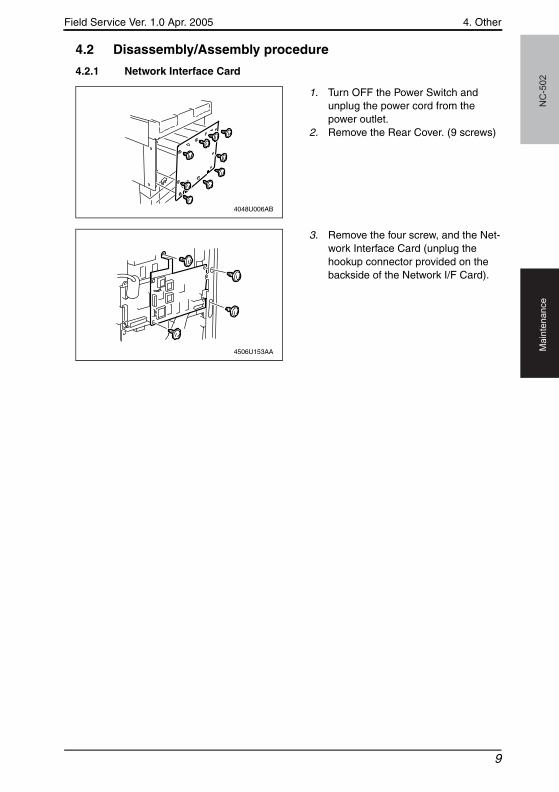
4.2.1 Network Interface Card
1. Turn OFF the Power Switch and unplug the power cord from the power outlet.
2. Remove the Rear Cover. (9 screws)
3. Remove the four screw, and the Net-work Interface Card (unplug the hookup connector provided on the backside of the Network I/F Card).
4048U006AB
4506U153AA
9
4. Other Field Service Ver. 1.0 Apr. 2005N
C-5
02
Ma
inte
na
nce
bizhub_162_210_FS.book 10 ページ 2005年4月18日 月曜日 午前10時5分
Blank page
10
Field Service Ver. 1.0 Apr. 2005 5. How to use the adjustment section
NC
-50
2A
dju
stm
en
t /
Se
ttin
g
bizhub_162_210_FS.book 11 ページ 2005年4月18日 月曜日 午前10時5分
Adjustment/Setting5. How to use the adjustment section• “Adjustment/Setting” contains detailed information on the adjustment items and proce-
dures for this machine.• Throughout this “Adjustment/Setting,” the default settings are indicated by “ ”.
A. Advance Checks• Before attempting to solve the customer problem, the following advance checks must be
made. Check to see if:
1. The power supply voltage meets the specifications.2. The power supply is properly grounded.3. The machine shares the power supply with any other machine that draws large current
intermittently (e.g., elevator and air conditioner that generate electric noise).4. The installation site is environmentally appropriate: high temperature, high humidity,
direct sunlight, ventilation, etc.; levelness of the installation site.5. The original has a problem that may cause a defective image.6. The density is properly selected.7. The Original Glass, slit glass, or related part is dirty.8. Correct paper is being used for printing.9. The units, parts, and supplies used for printing (developer, PC Drum, etc.) are properly
replenished and replaced when they reach the end of their useful service life.10. Toner is not running out.
B. Precautions for Service Jobs1. To unplug the power cord of the machine before starting the service job procedures.2. If it is unavoidably necessary to service the machine with its power turned ON, use
utmost care not to be caught in the Scanner Cables or gears of the Exposure Unit.3. Special care should be used when handling the Fusing Unit which can be extremely
hot.4. The Developing Unit has a strong magnetic field. Keep watches and measuring instru-
ments away from it.5. Take care not to damage the PC Drum with a tool or similar device.6. Do not touch IC pins with bare hands.
11
6. Utility Mode Field Service Ver. 1.0 Apr. 2005N
C-5
02
Ad
justm
en
t /
Se
ttin
g
bizhub_162_210_FS.book 12 ページ 2005年4月18日 月曜日 午前10時5分
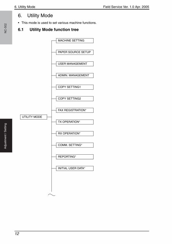
6. Utility Mode• This mode is used to set various machine functions.
6.1 Utility Mode function tree
UTILITY MODE
MACHINE SETTING
PAPER SOURCE SETUP
USER MANAGEMENT
ADMIN. MANAGEMENT
COPY SETTING1
COPY SETTING2
FAX REGISTRATION*
TX OPERATION*
RX OPERATION*
COMM. SETTING*
REPORTING*
INITIAL USER DATA*
12
Field Service Ver. 1.0 Apr. 2005 6. Utility Mode
NC
-50
2A
dju
stm
en
t /
Se
ttin
g
bizhub_162_210_FS.book 13 ページ 2005年4月18日 月曜日 午前10時5分
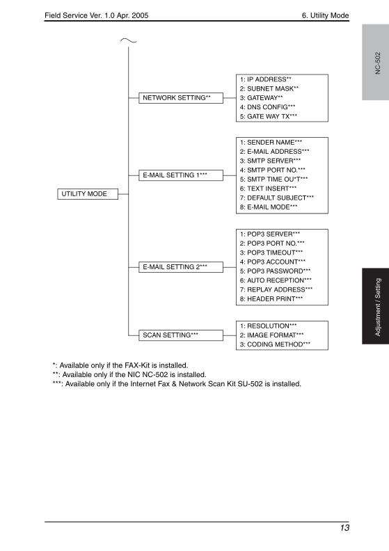
*: Available only if the FAX-Kit is installed.**: Available only if the NIC NC-502 is installed.***: Available only if the Internet Fax & Network Scan Kit SU-502 is installed.
UTILITY MODE
NETWORK SETTING**
1: IP ADDRESS**2: SUBNET MASK**3: GATEWAY**4: DNS CONFIG***5: GATE WAY TX***
E-MAIL SETTING 1***
1: SENDER NAME***2: E-MAIL ADDRESS***3: SMTP SERVER***4: SMTP PORT NO.***5: SMTP TIME OU*T***6: TEXT INSERT***7: DEFAULT SUBJECT***8: E-MAIL MODE***
E-MAIL SETTING 2***
1: POP3 SERVER***2: POP3 PORT NO.***3: POP3 TIMEOUT***4: POP3 ACCOUNT***5: POP3 PASSWORD***6: AUTO RECEPTION***7: REPLAY ADDRESS***8: HEADER PRINT***
1: RESOLUTION***2: IMAGE FORMAT***3: CODING METHOD***
SCAN SETTING***
13
6. Utility Mode Field Service Ver. 1.0 Apr. 2005N
C-5
02
Ad
justm
en
t /
Se
ttin
g
bizhub_162_210_FS.book 14 ページ 2005年4月18日 月曜日 午前10時5分
6.2 Utility Mode function setting procedure
6.2.1 Procedure
1. Press the Utility key.2. The first Utility mode screen appears.
6.2.2 Exiting
• Press the Panel Reset key.
6.2.3 Changing the setting value in Utility Mode functions
1. Press the ▲ / ▼ key, < / > key or the 10-Key Pad to select the desired function.2. Press the ▲ / ▼ key, < / > key or the 10-Key Pad to select the desired setting.3. Press the Yes key to apply the setting.4. To return to the previous screen, press the No / C key.
6.3 Setting in the Utility Mode
6.3.1 Network setting
• Depending on the network environment in which the machine is located, there may be some restrictions on the network functions that the machine can use. Make the network settings to suit the functions and environment required for customer’s location. The net-work settings can be specified from the control panel or using the administrator mode of PageScope Web Connection.
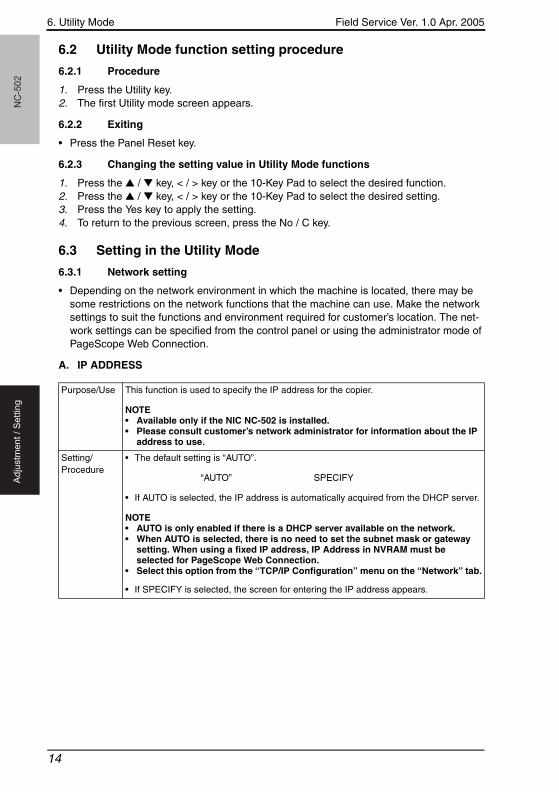
A. IP ADDRESS
Purpose/Use This function is used to specify the IP address for the copier.
NOTE• Available only if the NIC NC-502 is installed.• Please consult customer’s network administrator for information about the IP
address to use.
Setting/Procedure
• The default setting is “AUTO”.
“AUTO” SPECIFY
• If AUTO is selected, the IP address is automatically acquired from the DHCP server.
NOTE• AUTO is only enabled if there is a DHCP server available on the network.• When AUTO is selected, there is no need to set the subnet mask or gateway
setting. When using a fixed IP address, IP Address in NVRAM must be selected for PageScope Web Connection.
• Select this option from the “TCP/IP Configuration” menu on the “Network” tab.
• If SPECIFY is selected, the screen for entering the IP address appears.
14
Field Service Ver. 1.0 Apr. 2005 6. Utility Mode
NC
-50
2A
dju
stm
en
t /
Se
ttin
g
bizhub_162_210_FS.book 15 ページ 2005年4月18日 月曜日 午前10時5分
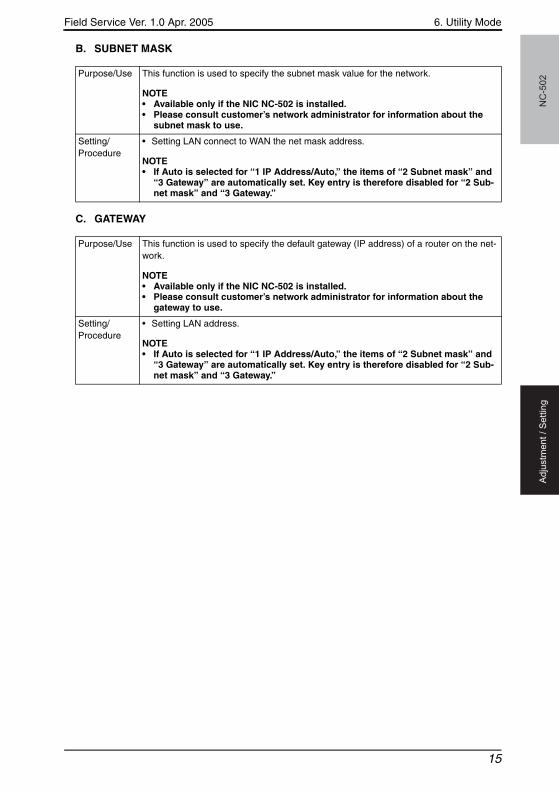
B. SUBNET MASK
C. GATEWAY
Purpose/Use This function is used to specify the subnet mask value for the network.
NOTE• Available only if the NIC NC-502 is installed.• Please consult customer’s network administrator for information about the
subnet mask to use.
Setting/Procedure
• Setting LAN connect to WAN the net mask address.
NOTE• If Auto is selected for “1 IP Address/Auto,” the items of “2 Subnet mask” and
“3 Gateway” are automatically set. Key entry is therefore disabled for “2 Sub-net mask” and “3 Gateway.”
Purpose/Use This function is used to specify the default gateway (IP address) of a router on the net-work.
NOTE• Available only if the NIC NC-502 is installed.• Please consult customer’s network administrator for information about the
gateway to use.
Setting/Procedure
• Setting LAN address.
NOTE• If Auto is selected for “1 IP Address/Auto,” the items of “2 Subnet mask” and
“3 Gateway” are automatically set. Key entry is therefore disabled for “2 Sub-net mask” and “3 Gateway.”
15
6. Utility Mode Field Service Ver. 1.0 Apr. 2005N
C-5
02
Ad
justm
en
t /
Se
ttin
g
bizhub_162_210_FS.book 16 ページ 2005年4月18日 月曜日 午前10時5分
Blank page
16
Field Service Ver. 1.0 Apr. 2005 7. Troubleshooting
NC
-50
2T
rou
ble
sh
oo
tin
g
bizhub_162_210_FS.book 17 ページ 2005年4月18日 月曜日 午前10時5分
Troubleshooting7. Troubleshooting
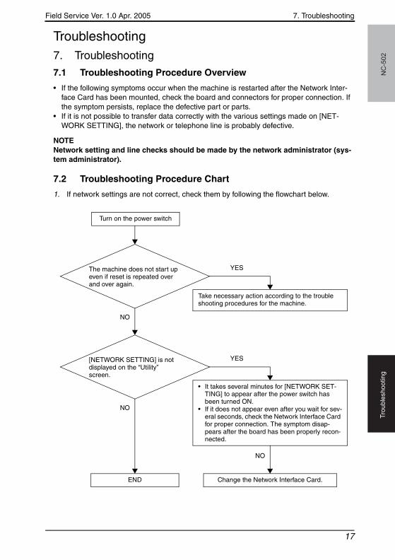
7.1 Troubleshooting Procedure Overview
• If the following symptoms occur when the machine is restarted after the Network Inter-face Card has been mounted, check the board and connectors for proper connection. If the symptom persists, replace the defective part or parts.
• If it is not possible to transfer data correctly with the various settings made on [NET-WORK SETTING], the network or telephone line is probably defective.
NOTENetwork setting and line checks should be made by the network administrator (sys-tem administrator).
7.2 Troubleshooting Procedure Chart
1. If network settings are not correct, check them by following the flowchart below.
Turn on the power switch
The machine does not start up even if reset is repeated over and over again.
Take necessary action according to the trouble shooting procedures for the machine.
YES
NO
[NETWORK SETTING] is not displayed on the “Utility” screen.
• It takes several minutes for [NETWORK SET-TING] to appear after the power switch has been turned ON.
• If it does not appear even after you wait for sev-eral seconds, check the Network Interface Card for proper connection. The symptom disap-pears after the board has been properly recon-nected.
YES
NO
NO
END Change the Network Interface Card.
17
7. Troubleshooting Field Service Ver. 1.0 Apr. 2005N
C-5
02
Tro
ub
lesh
oo
tin
g
bizhub_162_210_FS.book 18 ページ 2005年4月18日 月曜日 午前10時5分
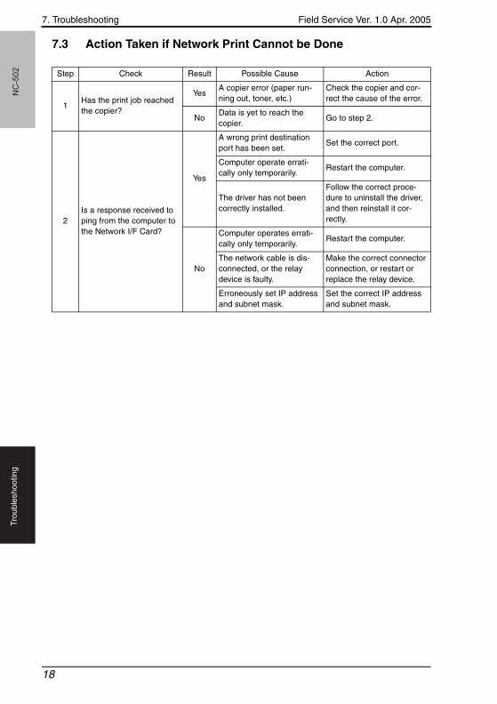
7.3 Action Taken if Network Print Cannot be Done
Step Check Result Possible Cause Action
1Has the print job reached the copier?
YesA copier error (paper run-ning out, toner, etc.)
Check the copier and cor-rect the cause of the error.
NoData is yet to reach the copier.
Go to step 2.
2Is a response received to ping from the computer to the Network I/F Card?
Yes
A wrong print destination port has been set.
Set the correct port.
Computer operate errati-cally only temporarily.
Restart the computer.
The driver has not been correctly installed.
Follow the correct proce-dure to uninstall the driver, and then reinstall it cor-rectly.
No
Computer operates errati-cally only temporarily.
Restart the computer.
The network cable is dis-connected, or the relay device is faulty.
Make the correct connector connection, or restart or replace the relay device.
Erroneously set IP address and subnet mask.
Set the correct IP address and subnet mask.
18