Embed Size (px)
Citation preview

V T
T
T I
E D
O T
T E
I T
A
2 0 0 2
Tauno Andstén, Hemmo Juutilainen, Jukka Vaari &Henry Weckman
Test method for actuating andsafety devices of portable fireextinguishersNordtest Project No. 1435–99
V T T R E S E A R C H N O T E S
TECHNICAL RESEARCH CENTRE OF FINLAND ESPOO 1999

VTT TIEDOTTEITA – MEDDELANDEN – RESEARCH NOTES 2002
TECHNICAL RESEARCH CENTRE OF FINLANDESPOO 1999
Test method for actuating andsafety devices of portable fire
extinguishers
Nordtest Project No. 1435–99
Tauno Andstén, Hemmo Juutilainen,Jukka Vaari & Henry Weckman
VTT Building Technology

SBN 951–38–5615–1 (soft back ed.)ISSN 1235–0605 (soft back ed.)
ISBN 951–38–5616–X (URL: http://www.inf.vtt.fi/pdf/)ISSN 1455–0865 (URL: http://www.inf.vtt.fi/pdf/)
Copyright © Valtion teknillinen tutkimuskeskus (VTT) 1999
JULKAISIJA – UTGIVARE – PUBLISHER
Valtion teknillinen tutkimuskeskus (VTT), Vuorimiehentie 5, PL 2000, 02044 VTTpuh. vaihde (09) 4561, faksi (09) 456 4374
Statens tekniska forskningscentral (VTT), Bergsmansvägen 5, PB 2000, 02044 VTTtel. växel (09) 4561, fax (09) 456 4374
Technical Research Centre of Finland (VTT), Vuorimiehentie 5, P.O.Box 2000, FIN–02044 VTT, Finlandphone internat. + 358 9 4561, fax + 358 9 456 4374
VTT Rakennustekniikka, Rakennusfysiikka, talo- ja palotekniikka, Kivimiehentie 4, PL 1803, 02044 VTTpuh. vaihde (09) 4561, faksi (09) 456 4815
VTT Byggnadsteknik, Byggnadsfysik, hus- och brandteknik, Stenkarlsvägen 4, PB 1803, 02044 VTTtel. växel (09) 4561, fax (09) 456 4815
VTT Building Technology, Building Physics, Building Services and Fire Technology,Kivimiehentie 4, P.O.Box 1803, FIN–02044 VTT, Finlandphone internat. + 358 9 4561, fax + 358 9 456 4815
Technical editing Maini Manninen
Libella Painopalvelu Oy, Espoo 1999
3
Andstén, Tauno; Juutilainen, Hemmo; Vaari, Jukka & Weckman, Henry. Test method for actuating andsafety devices of portable fire extinguishers. Nordtest Project No. 1435–99. Espoo 1999. TechnicalResearch Centre of Finland, VTT Tiedotteita – Meddelanden – Research Notes 2002. 40 p. + app. 25 p.
Keywords portable fire extinguishers, test methods, testing, safety devices, operation, measurements,actuating devices, test equipment, Nordtest
Abstract
The procedures included in the standard EN 3–5 for measuring the force required toactivate the operating devices and to release the safety devices of portable fireextinguishers are described only briefly and at a quite general level. As a consequence,the measurements may be carried out in different ways in different testing laboratorieswhich may lead to entirely different results.
In this study, a test procedure which has been in use for more than ten years at VTTBUILDING TECHNOLOGY has been further refined. The report includes sections ontheoretical considerations of the measurements as well as a description of the testequipment and results of several test series which were carried out. Based on thefindings, a proposal for a new Nordtest method is prepared. The method, which isintended to be used in conjunction with EN 3–5, focuses on controlling the factorswhich have the greatest influence on the measurements and which may distort theresults. As the designs of extinguishers and their actuating and safety devices in practiceare very variable and require individual mounting and fixing in the test device, themechanical design of the test device itself is not specified in any greater detail.

4
Preface
This study has been financially supported by Nordtest, the Rescue Department of theMinistry of the Interior and the Safety Technology Authority.
Of the authors, Tauno Andstén and Hemmo Juutilainen designed the test equipment andcarried out the experimental work. Jukka Vaari wrote the chapter on theoreticalconsiderations while Henry Weckman compiled the report. Tauno Andstén was theproject leader and responsible for the total management of the project work.
The authors are thankful to the financiers, to Dr. h.c. Toivo Pohja, who rebuilt the testequipment and to all our colleagues at VTT BUILDING TECHNOLOGY who supported usin various ways during the work.
The companies MAKO Oy, Oy Mercantile Ab, Oy Presto-tuote Ab and Softonex Oy Ltdprovided the seals, sealing wires and extinguishers used for the tests which is gratefullyacknowledged.
Espoo, 15 August 1999
Tauno Andstén Hemmo Juutilainen Jukka Vaari Henry Weckman
5
Contents
ABSTRACT...................................................................................................................... 3
PREFACE......................................................................................................................... 4
1. INTRODUCTION....................................................................................................... 7
2. COMMONLY USED TEST METHODS................................................................... 82.1 Test methods and requirements specified in EN 3–5 ......................................... 8
2.1.1 Operation and emission control mechanisms and devices ....................... 82.1.2 Safety devices........................................................................................... 9
2.2 Test methods and requirements in NT FIRE 024 ............................................... 92.2.1 Actuating devices ................................................................................... 102.2.2 Safety devices......................................................................................... 10
2.3 Earlier studies at VTT....................................................................................... 11
3. THEORETICAL CONSIDERATIONS.................................................................... 143.1 Compressive force acting on a squeeze grip..................................................... 14
3.1.1 Experimental set-up................................................................................ 143.1.2 Calculation of the torque acting on the grip ........................................... 153.1.3 Error analysis.......................................................................................... 17
3.2 Tensile force acting on a seal............................................................................ 193.2.1 Experimental set-up................................................................................ 193.2.2 Side load effects ..................................................................................... 19
4. EXPERIMENTAL .................................................................................................... 224.1 Principle............................................................................................................ 224.2 Test equipment.................................................................................................. 22
4.2.1 Test rig.................................................................................................... 234.2.2 Spindle motor ......................................................................................... 234.2.3 Load cell ................................................................................................. 244.2.4 Data acquisition and recording equipment............................................. 24
4.3 Calibration ........................................................................................................ 254.4 Test results ........................................................................................................ 28
4.4.1 Tests on safety devices ........................................................................... 284.4.2 Tests on actuating devices...................................................................... 314.4.3 Analysis of error sources ........................................................................ 34

6
5. SUMMARY .............................................................................................................. 39
REFERENCES ............................................................................................................... 40
APPENDICESAppendix A: Examples of typical operating mechanisms and security devicesAppendix B: Photographs of the test equipmentAppendix C: Proposal for a new Nordtest method

7
1. Introduction
The European standard EN 3–5 [1] defines the maximum force required to release thesafety device and to activate the operating device of portable fire extinguishers. Thedefined forces are important as they relate directly to the usability and safety of theextinguisher. The standard does not, however, contain detailed instructions on how themeasurements of the forces should be carried out. For this reason a well documentedmethod is needed by testing laboratories in order to obtain repeatable and reproducibleresults.
The aim of this study is to develop and document a method which could complementthe current brief description included in EN 3–5 [1]. The study also comprises anassessment of the accuracy of the new method and a proposal for a formal Nordtest testmethod. The new method could be used for an initial trial period by the Nordic firetesting laboratories and at a later stage it could be incorporated in a future revisedversion of the standard EN 3.
Chapter 2 of this report presents the requirements and methods of measurement for themaximum force required to release the safety device and to activate the operating deviceof portable fire extinguishers as described in the European standard EN 3–5 [1] and alsoin the recently withdrawn Nordic test method NT FIRE 024 [2]. This chapter alsodescribes the test procedures which were used prior to this study at VTT BUILDING
TECHNOLOGY.
Chapter 3 contains a discussion of various theoretical aspects related to measurementsof the forces required to operate a portable fire extinguisher. Chapter 4 describes theexperimental work carried out in this study including a description of the test equipmentwith calibration methods and experimental results. Chapter 5 contains a short discussionof the new test method.
Appendix A presents some common types of actuating and safety devices used inportable fire extinguisher. Appendix B contains photographs of the new test devicewhile Appendix C contains the formal proposal for a new Nordtest test method.
8
2. Commonly used test methods
2.1 Test methods and requirements specified in EN 3–5
Appendix A shows some typical examples of operation mechanisms and securitydevices used in current portable fire extinguishers.
2.1.1 Operation and emission control mechanisms and devices
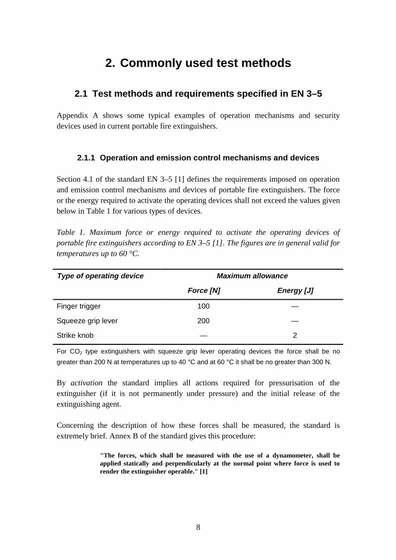
Section 4.1 of the standard EN 3–5 [1] defines the requirements imposed on operationand emission control mechanisms and devices of portable fire extinguishers. The forceor the energy required to activate the operating devices shall not exceed the values givenbelow in Table 1 for various types of devices.
Table 1. Maximum force or energy required to activate the operating devices ofportable fire extinguishers according to EN 3–5 [1]. The figures are in general valid fortemperatures up to 60 °C.
Type of operating device Maximum allowance
Force [N] Energy [J]
Finger trigger 100 —
Squeeze grip lever 200 —
Strike knob — 2
For CO2 type extinguishers with squeeze grip lever operating devices the force shall be no
greater than 200 N at temperatures up to 40 °C and at 60 °C it shall be no greater than 300 N.
By activation the standard implies all actions required for pressurisation of theextinguisher (if it is not permanently under pressure) and the initial release of theextinguishing agent.
Concerning the description of how these forces shall be measured, the standard isextremely brief. Annex B of the standard gives this procedure:
"The forces, which shall be measured with the use of a dynamometer, shall beapplied statically and perpendicularly at the normal point where force is used torender the extinguisher operable." [1]
9
The method to be used for measuring the energy required to activate extinguishers withoperating devices of the strike knob type is sufficiently well defined in Annex F of thestandard, and these devices will therefore not be further considered in this report.
For full compliance testing of portable fire extinguishers, the tests on the operatingdevices shall be carried out using six extinguishers, four of which have been subjectedto the temperature cycle defined in section 3.1 and Annex A of EN 3–5 [1] and two ofwhich have been subjected to external corrosion conditions defined in section 5.1 andAnnex H.1 of EN 3–5 [1]. This requirement is specified in the standard EN 3–6 [3].
2.1.2 Safety devices
According to section 4.2 of the standard EN 3–5 [1], the release of the safety deviceshall require a force between the limits of 20 N and 100 N. The standard does not,however, describe how the measurements shall be carried out.
The standard also requires that the safety devices shall be so constructed that anyunaided manual attempt, using a force or impact equal to twice the relevant value givenin Table 1, to initiate discharge without first operating the safety device shall not deformor break any part of the mechanism in such a way as to prevent the subsequent dischargeof the extinguisher.
In addition to these requirements, the standard also contains a number of qualitativerequirements imposed on the construction and operation of safety devices of portablefire extinguishers.
According to the standard EN 3–6 [3], for full compliance testing, the tests on the safetydevices shall be carried out using six extinguishers, four of which have been subjectedto the temperature cycle defined in section 3.1 and Annex A of EN 3–5 [1] and two ofwhich have been subjected to external corrosion conditions defined in section 5.1 andAnnex H.1 of EN 3–5 [1]. Additionally one test shall also be carried out on theoperating device of an extinguisher without first releasing the safety device. The force tobe applied in this case shall be equal to twice the respective value given in Table 1.
2.2 Test methods and requirements in NT FIRE 024
The Nordic test method NT FIRE 024 [2] has been withdrawn in May 1997. This was aconsequence of the acceptance of the European standard series EN 3 which in practicemade national and regional standards obsolete in the CEN member countries.

10
2.2.1 Actuating devices
Section 5.2.7 b) of NT FIRE 024 [2] specifies a number of requirements which must bemet by actuating devices of portable fire extinguishers. The force required to actuatedischarge may not exceed the values given in Table 2.
Table 2. Maximum force required to activate the operating devices of portable fireextinguishers according to NT FIRE 024 [2].
Type of operating device Maximum force [N]
Squeeze grip with one finger 100
Squeeze grip with whole hand 2001)
Impact button 400
1) For CO2 type extinguishers 300 N.
NT FIRE 024 gives a slightly more detailed description of the test procedure than thestandard EN 3–5 does. Sections 7.9 b) and 7.9 c) of the test method state:
"The measuring device shall permit the actuating force to be read off to an accuracyof ± 5 N within the measuring range 50 – 450 N.
The extinguisher is positioned vertically, force is applied to the outermost part of thecontrol device respectively the centre of the impact button with a force increase ofmax 100 N/s. The force required to press the control device all the way down isrecorded by means of a pressure gauge, weighing equipment etc." [2]
Even though the descriptions in both EN 3–5 and NT FIRE 024 are somewhat brief,they contain, however, an important difference. Regarding the point where the forceshall be applied in tests on extinguishers with a squeeze grip lever, EN 3–5 specifies "atthe normal point where force is used to render the extinguisher operable", while NTFIRE 024 specifies "to the outermost part of the control device".
Concerning the requirements on extinguishers with a strike knob, EN 3–5 specifies amaximum value expressed in energy units [2 J], while NT FIRE 024 gives the value inforce units [400 N].
2.2.2 Safety devices
Section 7.2 a) of NT FIRE 024 [2] prescribes that the seal used for sealing the safetydevice shall break when it is subjected to a tensile force of 50 ± 30 N. Contrary to EN3–5, NT FIRE 024 contains a description of the method to be used for measuring theforce required to release the safety device. Section 7.10.1 includes the following:
11
"Equipment: Dynamometer that permits measurement of tensile force with anaccuracy of 5 N.
Testing: 6 safety devices are fitted and sealed for testing in a manner equivalent tomounting on the extinguisher. A dynamometer is connected to the safety devices.The tensile force required to release the safety devices is measured" [2]
Similarly to EN 3–5 also NT FIRE 024 contains various other, mostly qualitative,requirements on the safety devices.
There is also a minor difference between EN 3–5 and NT FIRE 024 regarding safetydevices. NT FIRE 024 presumes that only tensile force will be used to release the safetydevices, while EN 3–5 does not include such a restriction.
2.3 Earlier studies at VTT
In 1987, shortly after the Nordic test method NT FIRE 024 [2] was accepted, aninvestigation was conducted at VTT BUILDING TECHNOLOGY where the consequences ofthe new method were studied [4]. In connection with this study also a number of newtest devices were designed. One of these was an equipment which was used formeasuring the force required to activate a portable fire extinguisher and the forcerequired to release the safety device of the extinguisher.
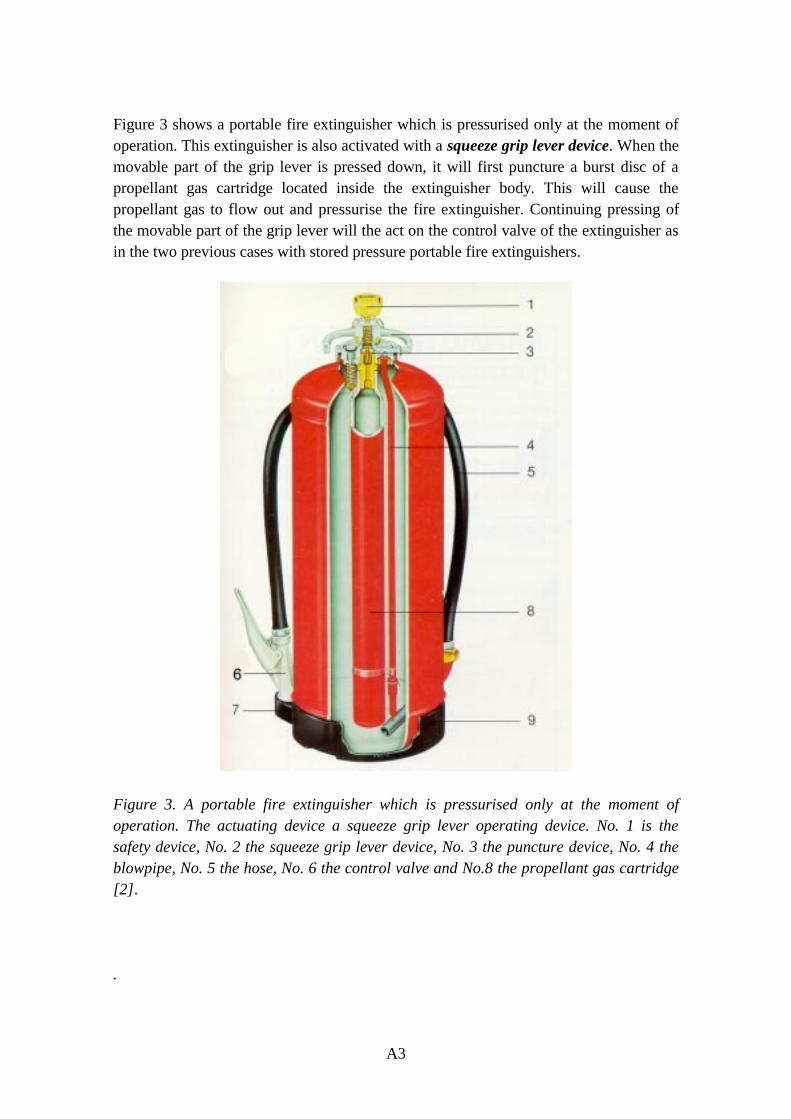
Figure 1 shows a photograph of the new test equipment which was developed in thisstudy. The new version is a slightly revised version of the original design from 1987.Both the new and the old test equipment consists of these main components: a heavymetal rig, mounting brackets, electric spindle motor, load cell and data acquisition andrecording devices.
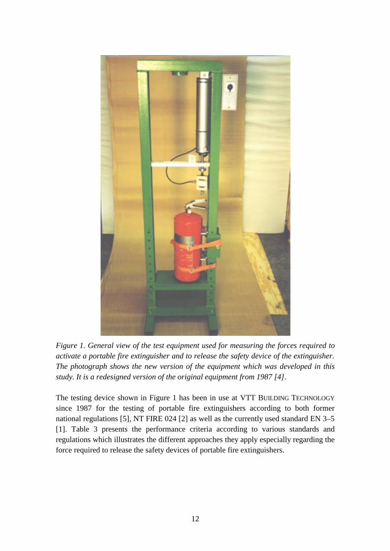
12
Figure 1. General view of the test equipment used for measuring the forces required toactivate a portable fire extinguisher and to release the safety device of the extinguisher.The photograph shows the new version of the equipment which was developed in thisstudy. It is a redesigned version of the original equipment from 1987 [4].
The testing device shown in Figure 1 has been in use at VTT BUILDING TECHNOLOGY
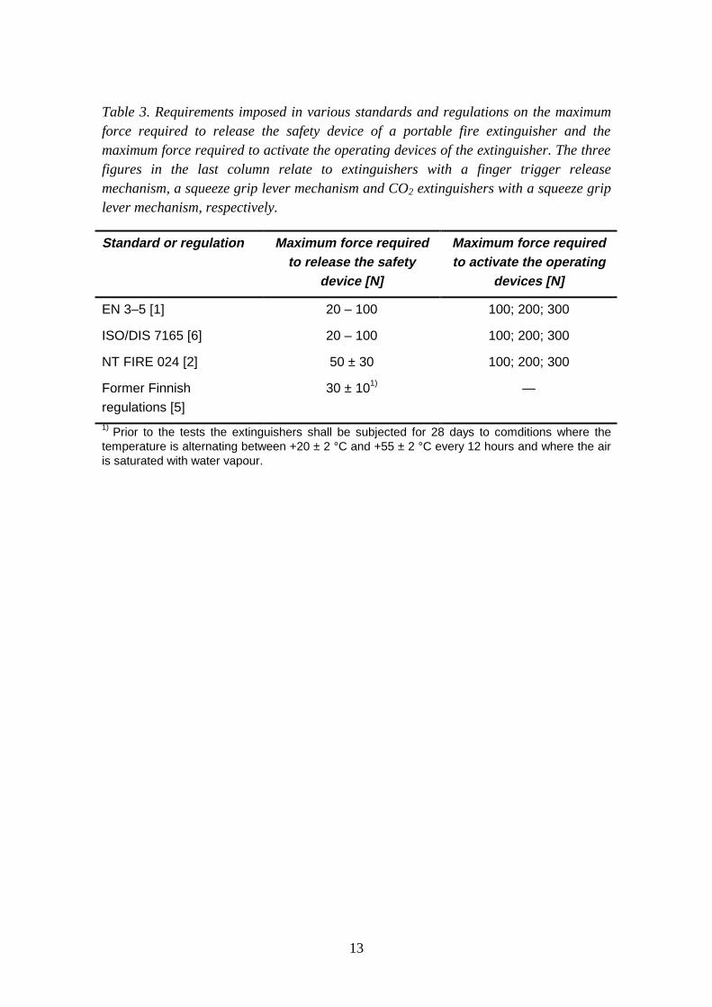
since 1987 for the testing of portable fire extinguishers according to both formernational regulations [5], NT FIRE 024 [2] as well as the currently used standard EN 3–5[1]. Table 3 presents the performance criteria according to various standards andregulations which illustrates the different approaches they apply especially regarding theforce required to release the safety devices of portable fire extinguishers.
13
Table 3. Requirements imposed in various standards and regulations on the maximumforce required to release the safety device of a portable fire extinguisher and themaximum force required to activate the operating devices of the extinguisher. The threefigures in the last column relate to extinguishers with a finger trigger releasemechanism, a squeeze grip lever mechanism and CO2 extinguishers with a squeeze griplever mechanism, respectively.
Standard or regulation Maximum force requiredto release the safety
device [N]
Maximum force requiredto activate the operating
devices [N]
EN 3–5 [1]
ISO/DIS 7165 [6]
NT FIRE 024 [2]
Former Finnish
regulations [5]
20 – 100
20 – 100
50 ± 30
30 ± 101)
100; 200; 300
100; 200; 300
100; 200; 300
—
1) Prior to the tests the extinguishers shall be subjected for 28 days to comditions where thetemperature is alternating between +20 ± 2 °C and +55 ± 2 °C every 12 hours and where the airis saturated with water vapour.
14
3. Theoretical considerations
3.1 Compressive force acting on a squeeze grip
3.1.1 Experimental set-up
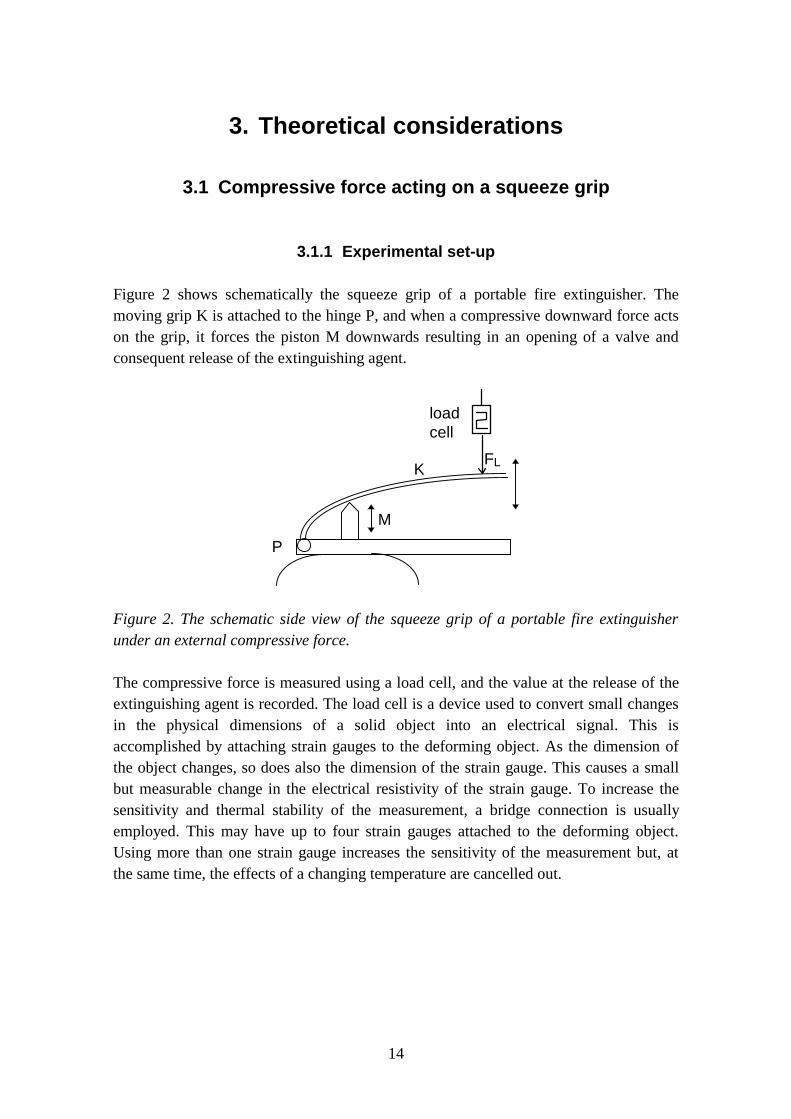
Figure 2 shows schematically the squeeze grip of a portable fire extinguisher. Themoving grip K is attached to the hinge P, and when a compressive downward force actson the grip, it forces the piston M downwards resulting in an opening of a valve andconsequent release of the extinguishing agent.
K
M
P
FL
loadcell
Figure 2. The schematic side view of the squeeze grip of a portable fire extinguisherunder an external compressive force.
The compressive force is measured using a load cell, and the value at the release of theextinguishing agent is recorded. The load cell is a device used to convert small changesin the physical dimensions of a solid object into an electrical signal. This isaccomplished by attaching strain gauges to the deforming object. As the dimension ofthe object changes, so does also the dimension of the strain gauge. This causes a smallbut measurable change in the electrical resistivity of the strain gauge. To increase thesensitivity and thermal stability of the measurement, a bridge connection is usuallyemployed. This may have up to four strain gauges attached to the deforming object.Using more than one strain gauge increases the sensitivity of the measurement but, atthe same time, the effects of a changing temperature are cancelled out.
15
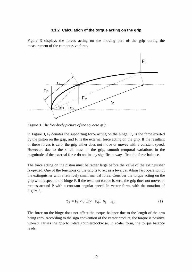
3.1.2 Calculation of the torque acting on the grip
Figure 3 displays the forces acting on the moving part of the grip during themeasurement of the compressive force.
r1
r2
FP
FL
FM
ϕ1 ϕ2
Figure 3. The free-body picture of the squeeze grip.
In Figure 3, FP denotes the supporting force acting on the hinge, FM is the force exertedby the piston on the grip, and FL is the external force acting on the grip. If the resultantof these forces is zero, the grip either does not move or moves with a constant speed.However, due to the small mass of the grip, smooth temporal variations in themagnitude of the external force do not in any significant way affect the force balance.
The force acting on the piston must be rather large before the valve of the extinguisheris opened. One of the functions of the grip is to act as a lever, enabling fast operation ofthe extinguisher with a relatively small manual force. Consider the torque acting on thegrip with respect to the hinge P. If the resultant torque is zero, the grip does not move, orrotates around P with a constant angular speed. In vector form, with the notation ofFigure 3,
τP P M LF r F r F= × + × + ×0 1 2 . (1)
The force on the hinge does not affect the torque balance due to the length of the armbeing zero. According to the sign convention of the vector product, the torque is positivewhen it causes the grip to rotate counterclockwise. In scalar form, the torque balancereads
16
F r F r F r F rM L M L1 1 2 2 1 1 2 22 20sin sin cos cos .
π ϕ π ϕ ϕ ϕ−
− −
= − = (2)
The magnitude of the external compressive force is then
F Fr
rL M= 1 1
2 2
cos
cos.
ϕϕ
(3)
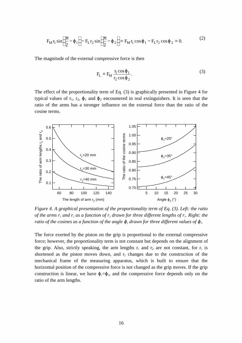
The effect of the proportionality term of Eq. (3) is graphically presented in Figure 4 fortypical values of r1, r2, ϕ1 and ϕ2 encountered in real extinguishers. It is seen that theratio of the arms has a stronger influence on the external force than the ratio of thecosine terms.
0.6
0.5
0.4
0.3
0.2
0.1The
rat
io o
f arm
leng
ths
r 1 an
d r 2
1401201008060
The length of arm r2 (mm)
r1=20 mm
r1=30 mm
r1=40 mm
1.05
1.00
0.95
0.90
0.85
0.80
0.75
0.70
The
rat
io o
f the
cos
ine
term
s
30252015105
Angle ϕ2 (°)
ϕ1=25°
ϕ1=35°
ϕ1=45°
Figure 4. A graphical presentation of the proportionality term of Eq. (3). Left: the ratioof the arms r1 and r2 as a function of r2 drawn for three different lengths of r1. Right: theratio of the cosines as a function of the angle ϕ2 drawn for three different values of ϕ1.
The force exerted by the piston on the grip is proportional to the external compressiveforce; however, the proportionality term is not constant but depends on the alignment ofthe grip. Also, strictly speaking, the arm lengths r1 and r2 are not constant, for r1 isshortened as the piston moves down, and r2 changes due to the construction of themechanical frame of the measuring apparatus, which is built to ensure that thehorizontal position of the compressive force is not changed as the grip moves. If the gripconstruction is linear, we have ϕ1=ϕ2, and the compressive force depends only on theratio of the arm lengths.
17
3.1.3 Error analysis
The primary factor causing uncertainty in the measurement of the compressive force isthe uncertainty in the arm length r2. This is simply because the grip construction changesfrom one extinguisher to another, and it becomes difficult to unambiguously determinethe point on which the compressive force should be exerted. Such a point is not given inthe standard EN 3–5 [1]. If the angle ϕ2 is large, there is more uncertainty due to the factthat as the exertion point of the compressive force moves along the surface of the grip,ϕ2 depends on r2. As these factors depend on the geometry of the grip, quantitative erroranalysis should be done on a case-by-case basis.
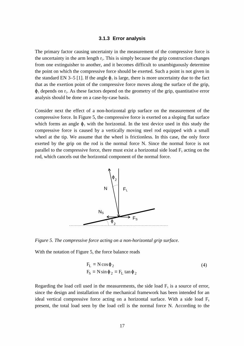
Consider next the effect of a non-horizontal grip surface on the measurement of thecompressive force. In Figure 5, the compressive force is exerted on a sloping flat surfacewhich forms an angle ϕ2 with the horizontal. In the test device used in this study thecompressive force is caused by a vertically moving steel rod equipped with a smallwheel at the tip. We assume that the wheel is frictionless. In this case, the only forceexerted by the grip on the rod is the normal force N. Since the normal force is notparallel to the compressive force, there must exist a horizontal side load FS acting on therod, which cancels out the horizontal component of the normal force.
ϕ
ϕ
FLN
FS
NS
2
2
Figure 5. The compressive force acting on a non-horizontal grip surface.
With the notation of Figure 5, the force balance reads
F N
F N FL
S L
== =
cos
sin tan
ϕϕ ϕ
2
2 2
(4)
Regarding the load cell used in the measurements, the side load FS is a source of error,since the design and installation of the mechanical framework has been intended for anideal vertical compressive force acting on a horizontal surface. With a side load FS
present, the total load seen by the load cell is the normal force N. According to the
18
technical specification of the load cell, the side load effect is 0.05 % of the applied loadat 1º cone from the axis, and 0.2 % of the applied load at 3° cone from the axis.Theoretically, the side load effect becomes
N NN
−= −
coscos .
ϕϕ2
21(5)
This gives a 0.015 % effect for 1º cone and a 0.14 % effect for the 3º cone, somewhatunderestimating the real side load effect, which may have other contributions as well.
Next we consider the time resolution requirement of the measurement. Assume that thetime-dependent compressive force FL(t) has to press the grip downward a verticaldistance of zL before the valve is opened. The measurement apparatus works such thatthe force-exerting steel rod moves down with a constant speed vL. Thus, themeasurement will be completed in a time given by tL=zL/vL. When the valve opens, theforce exerted by the piston on the grip drops suddenly. The error in the determination forthe triggering force becomes then the difference between the real triggering force andthe most recent measurement of the compressive force. It is evident that to improve theaccuracy, the speed vL must be made small or alternatively the time resolution ∆t has tobe chosen such that a sufficient number of force measurements can be made in time tL.For example, if tL/∆t=100, and the force FL is a linear function of time until thetriggering of the valve, the error caused by the finite time resolution to the determinationof the triggering force becomes 1 % at maximum.
Finally, it should be noted that the above discussion relates to the mechanics of the gripand the load cell. The actual release mechanism inside the extinguishers is notconsidered here in detail. However, in most extinguishers, the extinguishing agent ispressurised, and the release of the agent is simply achieved by a valve held closed by asteel spring. The moving piston must then overcome the force exerted by the spring, andthis force is proportional to the compression of the spring. This causes no additionalconsiderations to the torque calculation presented above.
A small class of extinguishers is constructed such that when the grip is squeezed, theextinguishing agent is first pressurised and then released. The pressurisation of theextinguishing agent involves a punctuation of a membrane beyond which thepressurising gas is stored in a small cylinder. The mechanics of the punctuation dependson the speed with which the piston moves towards the membrane. If the grip is presseddown very fast, the punctuation may require a different force compared to the case of aslow pressing. The mechanism of the punctuation may also be different; for example,very slow pressing of the grip may result in incomplete punctuation, which causes thede-pressurisation of the extinguisher with no extinguishing agent delivered. Strictly, the
19
relevant quantity that should be measured in this case is the impulse by the piston on themembrane. These aspects are, however, outside this study.
3.2 Tensile force acting on a seal
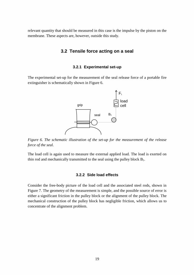
3.2.1 Experimental set-up
The experimental set-up for the measurement of the seal release force of a portable fireextinguisher is schematically shown in Figure 6.
seal
grip
B1
FL
loadcell
Figure 6. The schematic illustration of the set-up for the measurement of the releaseforce of the seal.
The load cell is again used to measure the external applied load. The load is exerted onthin rod and mechanically transmitted to the seal using the pulley block B1.
3.2.2 Side load effects
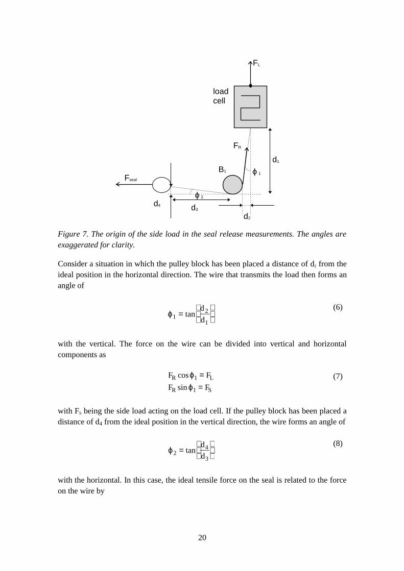
Consider the free-body picture of the load cell and the associated steel rods, shown inFigure 7. The geometry of the measurement is simple, and the possible source of error iseither a significant friction in the pulley block or the alignment of the pulley block. Themechanical construction of the pulley block has negligible friction, which allows us toconcentrate of the alignment problem.
20
FL
loadcell
Fseal
d1
d3
d2
B1
d4
ϕ 1
ϕ 2
FR
Figure 7. The origin of the side load in the seal release measurements. The angles areexaggerated for clarity.
Consider a situation in which the pulley block has been placed a distance of d2 from theideal position in the horizontal direction. The wire that transmits the load then forms anangle of
ϕ12
1=
tan
d
d
(6)
with the vertical. The force on the wire can be divided into vertical and horizontalcomponents as
F F
F FR L
R S
cos
sin
ϕϕ
1
1
==
(7)
with FS being the side load acting on the load cell. If the pulley block has been placed adistance of d4 from the ideal position in the vertical direction, the wire forms an angle of
ϕ24
3=
tan
d
d
(8)
with the horizontal. In this case, the ideal tensile force on the seal is related to the forceon the wire by
21
F Fseal R= cos .ϕ2 (9)
Combining the results, the applied load and the ideal tensile force on the seal are relatedby
F F Fd d d
d d dseal L L= =
+
+
cos
cos.
ϕϕ
2
1
3 12
22
1 32
42
(10)
In the ideal case we have ϕ1= ϕ 2=0 and therefore Fseal=FL. The force (including the sideload) seen by the load cell is FR, and the measured quantity thus relates to the tensileforce on the seal by
F F Fd
d dseal R R= =
+cos .ϕ2
3
32
42
(11)
Note that if the angle ϕ 2 is not zero, the measurement will overestimate the true tensileforce required to release the seal. In practice, the errors caused by the displacements d3
and d4 can be neglected as long as the angles ϕ1 and ϕ2 are of the order of a few degrees.

22
4. Experimental
The test equipment which was originally designed in 1987 was slightly redesigned forthis study. Appendix B contains photographs showing details of the current equipment.The main parts of the apparatus are still the same as before, i.e. a heavy metal rig,mounting brackets, electric spindle motor, load cell and data acquisition and recordingdevices. The components that underwent the greatest changes were the mechanical partsneeded for fixing and aligning the fire extinguisher firmly and correctly in the test rig forthe measurements.
4.1 Principle
For measuring the force required to activate the operating device of a portable fireextinguisher, the extinguisher is fixed firmly in the test rig and aligned in such a waythat the force exerted by the spindle motor will be directed perpendicularly at the normalpoint where force in practice will be used in order to render the extinguisher operable.The force exerted on the operating mechanism is measured continuously with the loadcell until the extinguishing agent is being discharged.
The measurements of the force required to release the safety device of the extinguisherare carried out in a similar way. However, the mounting position of the extinguisher willin most cases be different due to the location of the safety devices. For measuring tensileforces, various pulleys and wires may have to be used in order to correctly align thedirection of the force in relation to the location of the safety device. Also in this case thetensile force exerted on the safety device is measured continuously with the load celluntil the seal breaks.
Both measurements are carried out on six extinguishers as specified in EN 3–6 [3]. Priorto the tests the extinguishers are subjected to various environmental conditions requiredby the standard. The conditions were also presented above in section 2.1.2.
4.2 Test equipment
Appendix B contains photographs showing details of the test equipment used in thisstudy.
In addition to the equipment presented and shown here, a cyclone will be used forcollecting extinguishing powder being discharged during tests on powder extinguishers.
23
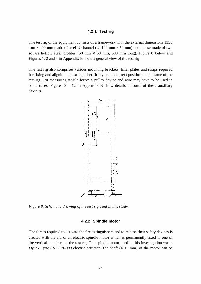
4.2.1 Test rig
The test rig of the equipment consists of a framework with the external dimensions 1350mm × 400 mm made of steel U channel (U: 100 mm × 50 mm) and a base made of twosquare hollow steel profiles (50 mm × 50 mm, 500 mm long). Figure 8 below andFigures 1, 2 and 4 in Appendix B show a general view of the test rig.
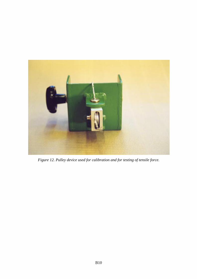
The test rig also comprises various mounting brackets, filler plates and straps requiredfor fixing and aligning the extinguisher firmly and in correct position in the frame of thetest rig. For measuring tensile forces a pulley device and wire may have to be used insome cases. Figures 8 – 12 in Appendix B show details of some of these auxiliarydevices.
Figure 8. Schematic drawing of the test rig used in this study.
4.2.2 Spindle motor
The forces required to activate the fire extinguishers and to release their safety devices iscreated with the aid of an electric spindle motor which is permanently fixed to one ofthe vertical members of the test rig. The spindle motor used in this investigation was aDynox Type CS 50/8–300 electric actuator. The shaft (ø 12 mm) of the motor can be
24
extended and retracted at a constant velocity of 9 mm/s. The maximum force exerted bythis device is 500 N.
The stroke length of the shaft is 300 mm, but it is here restricted to 50 mm with a crossmember of the framework (See Figures 1 and 8). The alignment of the shaft is furthersecured with the aid of a guiding pin, which can be seen in Figure 5 in Appendix B.
The shaft of the spindle motor is fixed to the upper part of the load cell mentioned in thenext section.
4.2.3 Load cell
The load cell used for the actual measurements of the force exerted in the tests on thefire extinguishers is the Model 606–S–100 manufactured by Tedea Ltd (Israel). Themaximum capacity of this load cell is 100 kg while its specified accuracy is 0.04 % ofthe rated output and temperature effect 0.0037 % of the load per °C. A force exerted onthe opposite ends of the load cell will cause a small deformation of the cell. Thedeformation is measured with the aid of four strain gauges mounted inside the cell. Thedeformation of the strain gauges causes a small change in the electrical resistivity of thestrain gauges. These changes in resistivity, which are proportional to the deformationand thus to the exerted force, can be measured with the aid of a Wheatstone bridge typecircuit. In this case a 6-wire full bridge circuit was being used.
The shaft of the spindle motor is fixed to bottom part of the load cell. As the same loadcell is used both for measuring both compressive and tensile force, an exchangeableplunger (see Fig. 5 in Appendix B) or hook assembly (see Figs. 6 and 7 in Appendix B)is mounted to the load cell depending on which force is to be measured. The free end ofthe plunger (ø 12 mm) is equipped with a roller (ø 16 mm, width 5 mm) in order toreduce the mechanical friction between the plunger and the grip of the operatingmechanism of the extinguisher. To further align the movement of the plunger and roller,a 6.5 mm thick aluminium plate (14 mm × 64 mm) with a groove matching the width ofthe roller was fixed to the grip with double-coated plastics tape. This aluminium platecan be seen on top of the upper lever of the extinguisher shown in Figure 5 in AppendixB.
4.2.4 Data acquisition and recording equipment
The output from the load cell, which in this case is of the order of one millivolt, isamplified with a linear DC amplifier (RS 846–171) in order to obtain voltages in a

25
usable range for ordinary data recording and acquisition equipment. The gain of theamplifier is approximately 1000.
The voltage from the amplifier is measured with the data acquisition device ModelDT2805 manufactured by Data Translation, Inc. This device is installed as a 16-bitexpansion board in the ISA bus of an ordinary PC type computer. The data acquisitioncard is controlled by the program Labtech Notebook for Windows, V. 9.02. The system iscapable of reading the voltage to be measured at a frequency of at least up to 900 Hz. Inthis study readings were taken at 10 and 100 measurements per second. The dataacquisition device converts the analogue voltages into digital values which are stored onthe hard disk on the computer by the controlling program. The data which is stored asordinary ASCII data on the hard disk can be retrieved and analysed by any suitablespreadsheet program. In this study the data processing was carried out with the programMicrosoft Excel 95®.
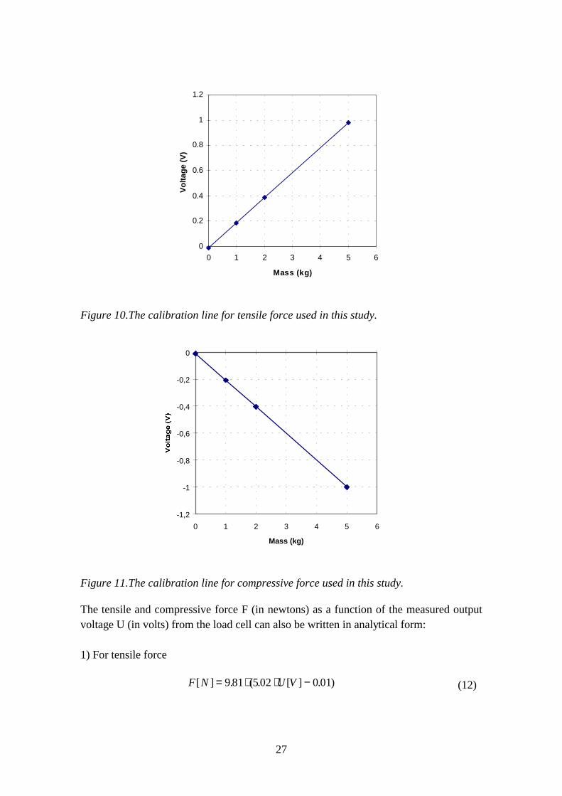
4.3 Calibration
The load cell was calibrated both without external load and with weights of 1, 2 and 5kg which were suspended from the hook assembly of the cell. Each weight was in turnsuspended from the hook for about 1 min while the voltage output from the load cellwas read at a frequency of 10 and 100 readings per second. Depending on whether thecell was calibrated for tensile or compressive force, the weights were either suspendeddirectly from the bottom hook of the hook assembly or from the upper hook via a pulleyattachment (see Figures 6 and 7 in Appendix B). The shaft of the spindle motor wasmoving upwards for calibration of the tensile force and downwards for the compressiveforce. The calibrations were carried out before the start of the actual test programme andafter it was finished more than one month later.
The force corresponding to each weight used for the calibration is obtained bymultiplying the mass of the weight by the acceleration of free fall (9.81 m/s2).
The results obtained in the two calibration series for both tensile and compressive forceare given in Table 4. Figure 9 shows the raw data measured during one of the tensilecalibration series.

26
Table 4. Results of calibration for tensile and compressive force. The first calibrationseries was carried out before the start of the actual test programme and the second afterit was finished over one month later.
Mass of the Measured voltage [V]
weight [kg] Tensile force Compressive force
1st calibr. 2nd calibr. 1st calibr. 2nd calibr.
0
1
2
5
–0.012
0.186
0.386
0.983
0.0075
0.188
0.388
0.985
–0.0098
–0.2075
–0.405
–1.001
–0.0075
–0.205
–0.4
–1.0
-0.2
0
0.2
0.4
0.6
0.8
1
1.2
0 50 100 150 200 250 300
Time (s)
Vol
tage
(V
)
Figure 9. Results of the first calibration for tensile force. The peaks are caused by theswaying weight suspended from the load cell.(Compressive force produces similarresults, but with negative voltage readings.)
Plotting the measured voltage vs. mass values of the first calibration series given inTable 4 gives the calibration lines shown in Figures 10 and 11. The measurementsvalues fit in both cases a straight line quite well as can be seen from the figures.
27
0
0.2
0.4
0.6
0.8
1
1.2
0 1 2 3 4 5 6
Mass (kg)
Vol
tage
(V
)
Figure 10.The calibration line for tensile force used in this study.
-1,2
-1
-0,8
-0,6
-0,4
-0,2
0
0 1 2 3 4 5 6
Mass (kg)
Figure 11.The calibration line for compressive force used in this study.
The tensile and compressive force F (in newtons) as a function of the measured outputvoltage U (in volts) from the load cell can also be written in analytical form:
1) For tensile force
F N U V[ ] . ( . [ ] . )= ⋅ ⋅ −9 81 502 0 01 (12)
28
For compressive force
)01.0][04.5(81.9][ −⋅−⋅= VUNF (13)
The statistical standard errors of the slopes of Equations (12) and (13) are ±0.004 and±0.005, respectively while the corresponding values for the Y-intercepts are ±0.002 and±0.003. The errors relate only to the constants inside the parenthesises.
Ideally, the expressions given in Equations (12) and (13) should be identical except forthe direction of the force. The small discrepancy between the two may be the result ofthe friction of the pulley that was used for suspending the weights for calibration of thecompressive force.
4.4 Test results
In order to evaluate the redesigned test equipment, three test series were carried out: (1)tests on safety devices; (2) tests on actuating devices and (3) analysis of error sources. Inthe analysis of error sources the effects of various misalignments of the test equipmentand other factors were studied.
The tests were carried out using different types of commercially available portable fireextinguishers.
4.4.1 Tests on safety devices
Two different extinguishers were used in this test series:• A 5 kg CO2 extinguisher with a squeeze grip lever actuating device.• A 2 kg powder extinguisher with a finger trigger actuating device.
Manufacturers and importers of extinguishers provided seals of three different types(two made of plastics and one of lead) and also sealing wires of three types (two madeof metal and one of plastics). Various combinations of seals and wires were used in thetests.
Prior to the tests, the safety devices of the extinguishers were sealed with the providedseals and wires. This operation was carried out manually in the laboratory using of a pairof pliers. Next, one extinguisher at a time was fixed in the test rig and the safety devicewas aligned in an appropriate position in relation to the load cell:
29
• The CO2 extinguisher was fixed in the test rig with its longitudinal axis in thevertical direction. The safety device of the squeeze grip lever mechanism was of thepull ring/locking pin type which is pulled out perpendicularly to the longitudinalaxis of the extinguisher. The ring was therefore fixed with a string via a pulleyattachment to the hook assembly of the load cell. In this case the force required torelease the safety device was measured as tensile force. (Figures 2 and 3 inAppendix B show the CO2 extinguisher being tested.)
• The powder extinguisher was mounted with its longitudinal axis in the horizontaldirection. The safety device of the finger trigger release mechanism consisted of asealed push button which is pushed down perpendicularly to the longitudinal axis ofthe extinguisher. The extinguisher was aligned so that the plunger assembly of theload cell acted directly on the push button. In this case the force required to releasethe safety device was measured as compressive force.
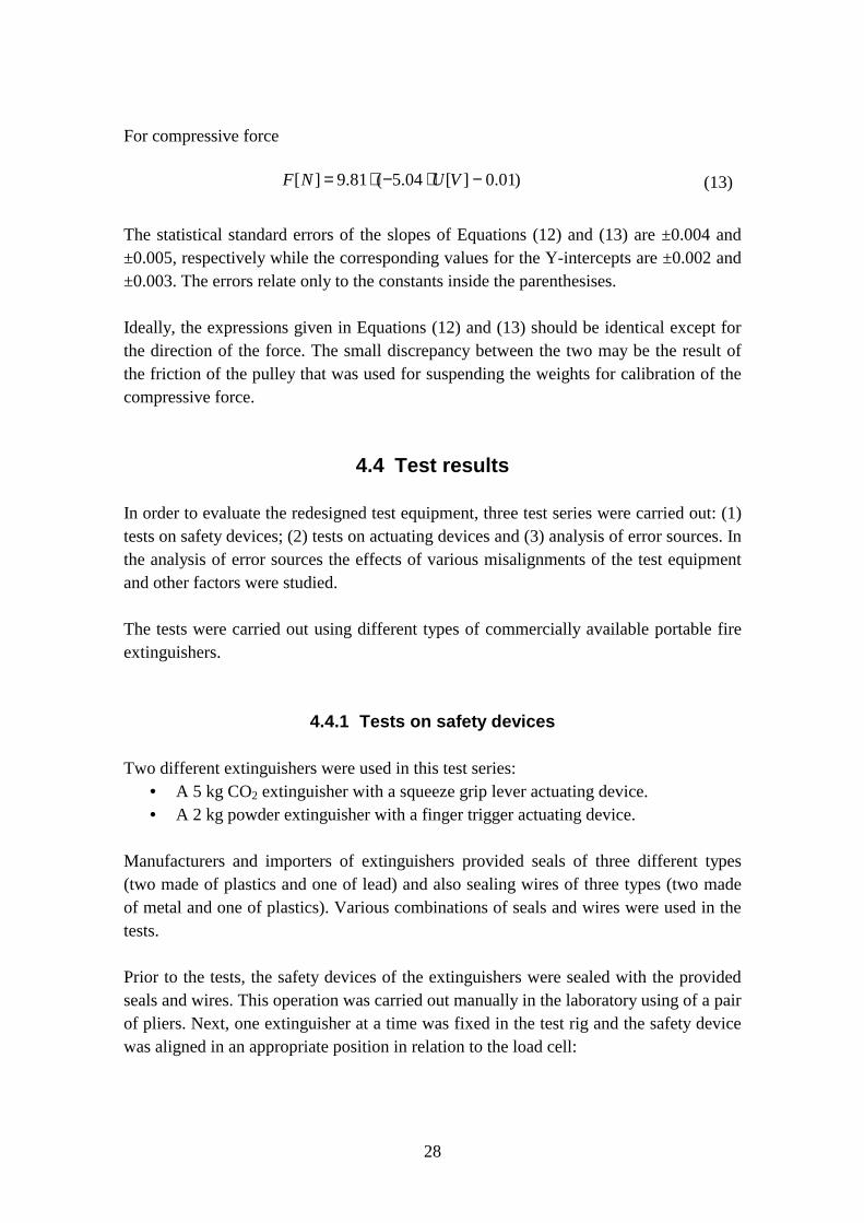
Next, the data acquisition system was activated and 60 s later the spindle motor wasswitched on in order to either raise or lower the shaft and load cell depending onwhether it was tensile or compressive force that was being measured. The test wascontinued until the safety device was unambiguously released. After this the dataacquisition system was switched off. Figure 12 shows an example of a typical forceversus time plot. During the measurement the force acting on the safety device slowlyincreases until the sealing wire breaks (at test time ~ 1.4 seconds) and the safety deviceis fully released. After this, the force rapidly decreases.
-5
0
5
10
15
20
25
30
0 0.5 1 1.5 2
Time (s)
For
ce (
N)
Figure 12. Example of a measurement of the force required to release the safety deviceof a portable fire extinguisher.
30
The maximum value of the time–force curve is the value that is being sought throughthese measurement and which is compared against the specified requirements.
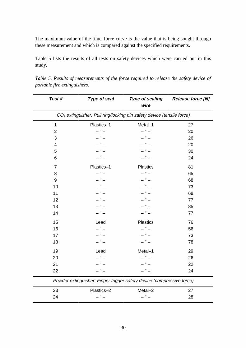
Table 5 lists the results of all tests on safety devices which were carried out in thisstudy.
Table 5. Results of measurements of the force required to release the safety device ofportable fire extinguishers.
Test # Type of seal Type of sealingwire
Release force [N]
CO2 extinguisher: Pull ring/locking pin safety device (tensile force)
1
2
3
4
5
6
7
8
9
10
11
12
13
14
15
16
17
18
19
20
21
22
Plastics–1
– " –
– " –
– " –
– " –
– " –
Plastics–1
– " –
– " –
– " –
– " –
– " –
– " –
– " –
Lead
– " –
– " –
– " –
Lead
– " –
– " –
– " –
Metal–1
– " –
– " –
– " –
– " –
– " –
Plastics
– " –
– " –
– " –
– " –
– " –
– " –
– " –
Plastics
– " –
– " –
– " –
Metal–1
– " –
– " –
– " –
27
20
26
20
30
24
81
65
68
73
68
77
85
77
76
56
73
78
29
26
22
24
Powder extinguisher: Finger trigger safety device (compressive force)
23
24
Plastics–2
– " –
Metal–2
– " –
27
28
31
The material of the wire used for sealing the safety device seems to have the greatestinfluence on the measured force. The average force for the two metal wires is 25.3 Nwith a standard deviation of 3.3 N while the average is 73.1 N and the standarddeviation 7.8 N for the plastics wire. The seal type does not seem to have any significantinfluence on the measured force in these limited test series.
The standard EN 3–5 [1] prescribes that the force required to release safety devices shallbe "between the limits of 20 N and 100 N". All 24 tests shown in Table 5 meet thisrequirement.
4.4.2 Tests on actuating devices
Three different portable fire extinguishers were used for these tests:• A 6 litre foam extinguisher with a squeeze grip lever actuating device.• A 5 kg CO2 extinguisher with a squeeze grip lever actuating device.• A 2 kg powder extinguisher with a finger trigger actuating device.
The foam extinguisher was charged either with nitrogen only at various pressures, with6 litres of plain water and nitrogen at 14 bar or with 6 litres of foam solution andnitrogen at 14 bar. The CO2 extinguisher was normally charged with carbon dioxide andthe tests were carried out at the temperatures +20 °C and +40 °C. The powderextinguisher was charged only with nitrogen at 14 bar.
For the tests each extinguisher in turn was fixed to the test rig and the actuating devicewas aligned in an appropriate position in relation to the load cell:
• The foam and CO2 extinguishers were fixed in the test rig with their longitudinalaxis in the vertical direction. The extinguishers were aligned so that the plungerassembly of the load cell acted directly on the upper lever of the squeeze gripactuating device. In this case the force required to activate the operating device wasmeasured as compressive force. (Figures 4 and 5 in Appendix B show the foamextinguisher being tested.)
• The powder extinguisher was mounted with its longitudinal axis in the horizontaldirection. The extinguisher was aligned so that the plunger assembly of the load cellacted directly on the finger trigger of the actuating device. Also in this case the forcerequired to activate the operating device was measured as compressive force.
After this, the data acquisition system was activated and 60 s later the spindle motor wasswitched on in order to lower the shaft and load cell with the plunger and press downthe actuating device of the extinguisher until the discharge was commenced. The data
32
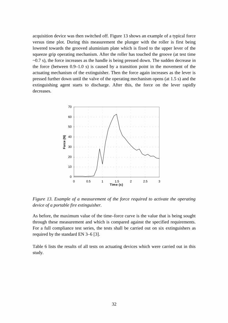
acquisition device was then switched off. Figure 13 shows an example of a typical forceversus time plot. During this measurement the plunger with the roller is first beinglowered towards the grooved aluminium plate which is fixed to the upper lever of thesqueeze grip operating mechanism. After the roller has touched the groove (at test time~0.7 s), the force increases as the handle is being pressed down. The sudden decrease inthe force (between 0.9–1.0 s) is caused by a transition point in the movement of theactuating mechanism of the extinguisher. Then the force again increases as the lever ispressed further down until the valve of the operating mechanism opens (at 1.5 s) and theextinguishing agent starts to discharge. After this, the force on the lever rapidlydecreases.
0
10
20
30
40
50
60
70
0 0.5 1 1.5 2 2.5 3Time (s)
For
ce (
N)
Figure 13. Example of a measurement of the force required to activate the operatingdevice of a portable fire extinguisher.
As before, the maximum value of the time–force curve is the value that is being soughtthrough these measurement and which is compared against the specified requirements.For a full compliance test series, the tests shall be carried out on six extinguishers asrequired by the standard EN 3–6 [3].
Table 6 lists the results of all tests on actuating devices which were carried out in thisstudy.
33
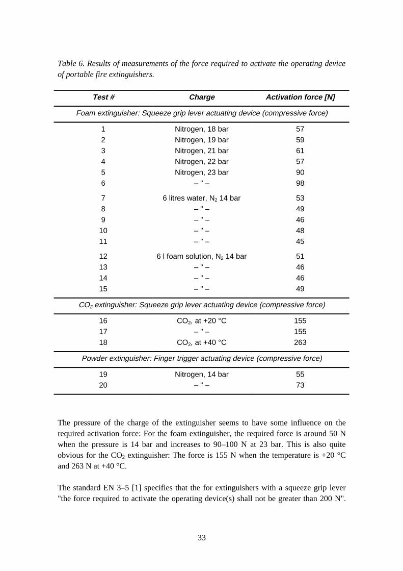
Table 6. Results of measurements of the force required to activate the operating deviceof portable fire extinguishers.
Test # Charge Activation force [N]
Foam extinguisher: Squeeze grip lever actuating device (compressive force)
1
2
3
4
5
6
7
8
9
10
11
12
13
14
15
Nitrogen, 18 bar
Nitrogen, 19 bar
Nitrogen, 21 bar
Nitrogen, 22 bar
Nitrogen, 23 bar
– " –
6 litres water, N2 14 bar
– " –
– " –
– " –
– " –
6 l foam solution, N2 14 bar
– " –
– " –
– " –
57
59
61
57
90
98
53
49
46
48
45
51
46
46
49
CO2 extinguisher: Squeeze grip lever actuating device (compressive force)
16
17
18
CO2, at +20 °C
– " –
CO2, at +40 °C
155
155
263
Powder extinguisher: Finger trigger actuating device (compressive force)
19
20
Nitrogen, 14 bar
– " –
55
73
The pressure of the charge of the extinguisher seems to have some influence on therequired activation force: For the foam extinguisher, the required force is around 50 Nwhen the pressure is 14 bar and increases to 90–100 N at 23 bar. This is also quiteobvious for the CO2 extinguisher: The force is 155 N when the temperature is +20 °Cand 263 N at +40 °C.
The standard EN 3–5 [1] specifies that the for extinguishers with a squeeze grip lever"the force required to activate the operating device(s) shall not be greater than 200 N".
34
For CO2 this value is valid for temperatures up to +40 °C. At +60 °C the maximumforce is 300 N. For extinguishers with a finger trigger the maximum force is 100 N. All20 tests shown in Table 6, except Test # 18, meet these requirements.
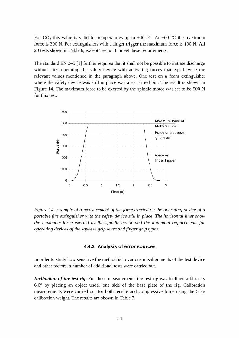
The standard EN 3–5 [1] further requires that it shall not be possible to initiate dischargewithout first operating the safety device with activating forces that equal twice therelevant values mentioned in the paragraph above. One test on a foam extinguisherwhere the safety device was still in place was also carried out. The result is shown inFigure 14. The maximum force to be exerted by the spindle motor was set to be 500 Nfor this test.
0
100
200
300
400
500
600
0 0.5 1 1.5 2 2.5 3
Time (s)
For
ce (
N)
Maximum force ofspindle motor
Force on squeezegrip lever
Force onfinger trigger
Figure 14. Example of a measurement of the force exerted on the operating device of aportable fire extinguisher with the safety device still in place. The horizontal lines showthe maximum force exerted by the spindle motor and the minimum requirements foroperating devices of the squeeze grip lever and finger grip types.
4.4.3 Analysis of error sources
In order to study how sensitive the method is to various misalignments of the test deviceand other factors, a number of additional tests were carried out.
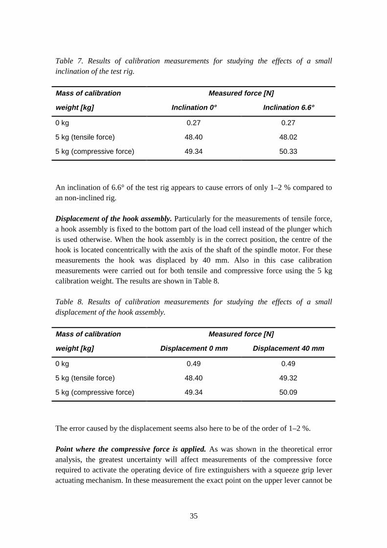
Inclination of the test rig. For these measurements the test rig was inclined arbitrarily6.6° by placing an object under one side of the base plate of the rig. Calibrationmeasurements were carried out for both tensile and compressive force using the 5 kgcalibration weight. The results are shown in Table 7.
35
Table 7. Results of calibration measurements for studying the effects of a smallinclination of the test rig.
Mass of calibration Measured force [N]
weight [kg] Inclination 0° Inclination 6.6°
0 kg
5 kg (tensile force)
5 kg (compressive force)
0.27
48.40
49.34
0.27
48.02
50.33
An inclination of 6.6° of the test rig appears to cause errors of only 1–2 % compared toan non-inclined rig.
Displacement of the hook assembly. Particularly for the measurements of tensile force,a hook assembly is fixed to the bottom part of the load cell instead of the plunger whichis used otherwise. When the hook assembly is in the correct position, the centre of thehook is located concentrically with the axis of the shaft of the spindle motor. For thesemeasurements the hook was displaced by 40 mm. Also in this case calibrationmeasurements were carried out for both tensile and compressive force using the 5 kgcalibration weight. The results are shown in Table 8.
Table 8. Results of calibration measurements for studying the effects of a smalldisplacement of the hook assembly.
Mass of calibration Measured force [N]
weight [kg] Displacement 0 mm Displacement 40 mm
0 kg
5 kg (tensile force)
5 kg (compressive force)
0.49
48.40
49.34
0.49
49.32
50.09
The error caused by the displacement seems also here to be of the order of 1–2 %.
Point where the compressive force is applied. As was shown in the theoretical erroranalysis, the greatest uncertainty will affect measurements of the compressive forcerequired to activate the operating device of fire extinguishers with a squeeze grip leveractuating mechanism. In these measurement the exact point on the upper lever cannot be
36
unambiguously defined in a test standard due to the very varied designs of practicalextinguishers. The standard EN 3–5 [1] calls for "at the normal point where force isused to render the extinguisher operable", while NT FIRE 024 [2] requires "to theoutermost part of the control device".
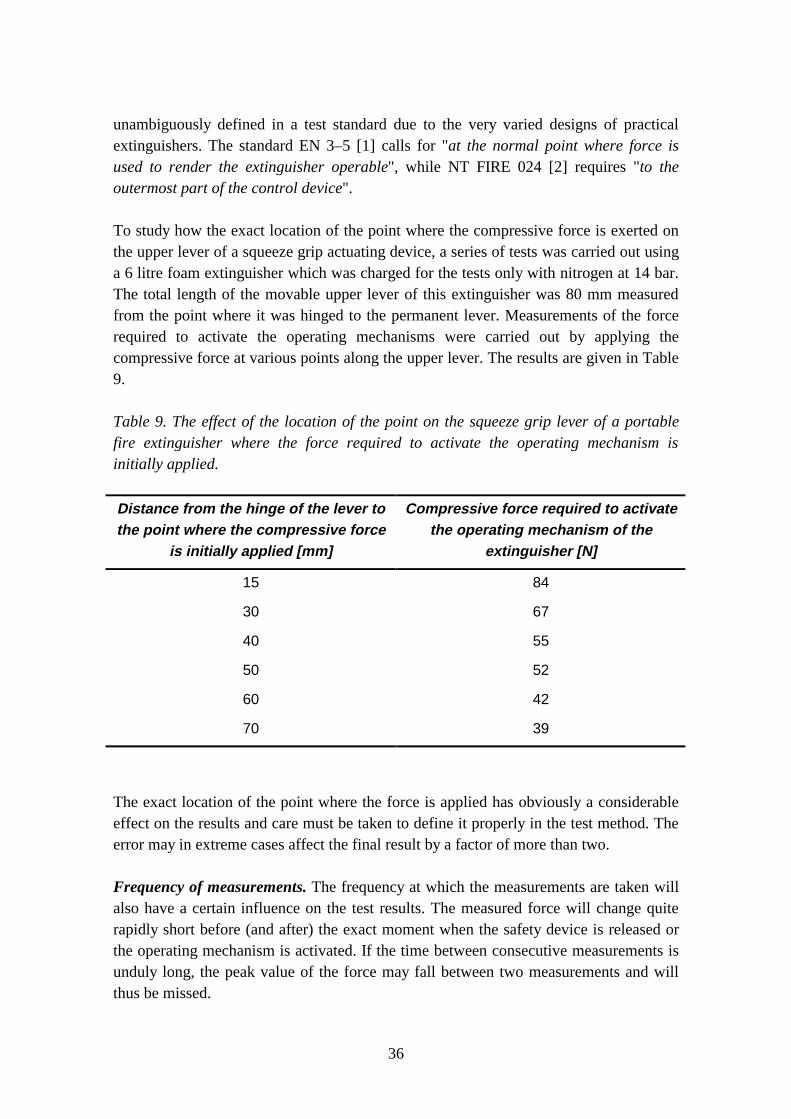
To study how the exact location of the point where the compressive force is exerted onthe upper lever of a squeeze grip actuating device, a series of tests was carried out usinga 6 litre foam extinguisher which was charged for the tests only with nitrogen at 14 bar.The total length of the movable upper lever of this extinguisher was 80 mm measuredfrom the point where it was hinged to the permanent lever. Measurements of the forcerequired to activate the operating mechanisms were carried out by applying thecompressive force at various points along the upper lever. The results are given in Table9.
Table 9. The effect of the location of the point on the squeeze grip lever of a portablefire extinguisher where the force required to activate the operating mechanism isinitially applied.
Distance from the hinge of the lever tothe point where the compressive force
is initially applied [mm]
Compressive force required to activatethe operating mechanism of the
extinguisher [N]
15
30
40
50
60
70
84
67
55
52
42
39
The exact location of the point where the force is applied has obviously a considerableeffect on the results and care must be taken to define it properly in the test method. Theerror may in extreme cases affect the final result by a factor of more than two.
Frequency of measurements. The frequency at which the measurements are taken willalso have a certain influence on the test results. The measured force will change quiterapidly short before (and after) the exact moment when the safety device is released orthe operating mechanism is activated. If the time between consecutive measurements isunduly long, the peak value of the force may fall between two measurements and willthus be missed.
37
In this study the frequencies 10 and 100 measurements per second were used. However,it was found that the time between two measurements may be slightly too long for thelower frequency. Figure 13 above shows an example of this. Between the test times 1.0s and 1.4 s, the force increases steadily and quite smoothly. Going to the next reading at1.5 s there is an obvious kink of the curve, and this reading is already a part of thedescending curve. The peak value would thus be somewhere between the readings 1.4 sand 1.5 s. From the increasing and decreasing sections of the curves, the peak value ofaround 66 N can be extrapolated. The reported maximum force was in this case 63 N, sothe difference would be 3 N or nearly 5 % which is somewhat greater than the errorscaused by misalignment of the test equipment.
Care must be taken to use a sufficiently high measurement frequency in order not tounduly distort the time–force curve and risk missing the peak values.
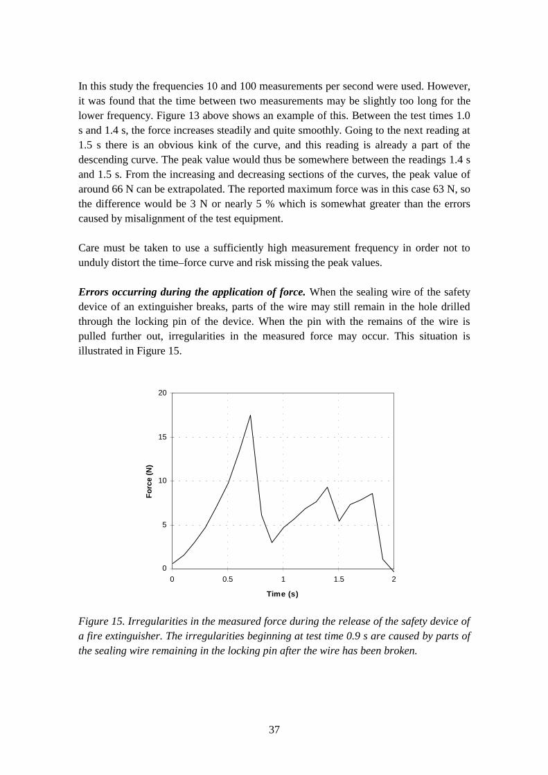
Errors occurring during the application of force. When the sealing wire of the safetydevice of an extinguisher breaks, parts of the wire may still remain in the hole drilledthrough the locking pin of the device. When the pin with the remains of the wire ispulled further out, irregularities in the measured force may occur. This situation isillustrated in Figure 15.
0
5
10
15
20
0 0.5 1 1.5 2
Time (s)
For
ce (
N)
Figure 15. Irregularities in the measured force during the release of the safety device ofa fire extinguisher. The irregularities beginning at test time 0.9 s are caused by parts ofthe sealing wire remaining in the locking pin after the wire has been broken.
38
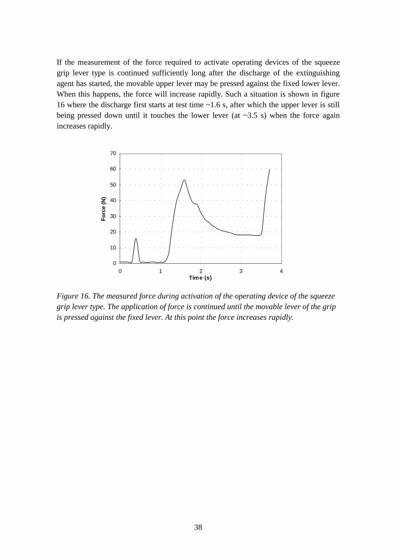
If the measurement of the force required to activate operating devices of the squeezegrip lever type is continued sufficiently long after the discharge of the extinguishingagent has started, the movable upper lever may be pressed against the fixed lower lever.When this happens, the force will increase rapidly. Such a situation is shown in figure16 where the discharge first starts at test time ~1.6 s, after which the upper lever is stillbeing pressed down until it touches the lower lever (at ~3.5 s) when the force againincreases rapidly.
0
10
20
30
40
50
60
70
0 1 2 3 4Time (s)
For
ce (
N)
Figure 16. The measured force during activation of the operating device of the squeezegrip lever type. The application of force is continued until the movable lever of the gripis pressed against the fixed lever. At this point the force increases rapidly.
39
5. Summary
The results of the experimental part of this study show that the method outlined here canbe used for measuring the force required to activate the operating devices and to releasethe safety devices of portable fire extinguishers. However, care must be taken toeliminate the factors which may distort the results.
Appendix C contains a proposal for a Nordtest method which specifies the principles tobe applied for measuring the forces discussed in this study. As the extinguishers inpractice are provided with actuating and safety devices of a very varied design whichrequire the extinguishers to be fixed in the test rig in various ways and positions tocorrectly align the extinguisher, the test rig itself is not described in any great detail inthe proposal. The draft test method focuses instead on the factors which are known toinfluence the test results, such as for instance the alignment of the components, the pointwhere the force is to be applied, the minimum frequency at which measurements are tobe made, etc. It is up to the user to find a suitable way of fixing the extinguisher in thecorrect position in relation to the force. This fixing may require the use of variousspacers, supports, fixtures and straps. The design of the extinguishers may furthermorerequire that the test force has to be applied as tensile force with the aid of pulleys andwires. Figures 8 – 12 in Appendix B contain examples of different auxiliary deviceswhich were used for the measurements carried out in this study. Particularly whentesting powder extinguishers, a cyclone or similar device may be useful for collectingthe discharged powder.
The proposal is presently written as a standalone test method, although it relies heavilyon the standard EN 3–5 [1]. The proposal can also easily be written as supplementaryspecifications containing only the description of the detailed test procedure. The latterprocedure has been used for instance in the Nordtest method NT FIRE 020 [7] whichcontains some supplementary specifications to the standard ISO 4736 [8].
40
References
1. EN 3–5, Portable fire extinguishers – Part 5: Specification and supplementary tests.Brussels, BE: European Committee for Standardization. 1995. 15 p.
2. NT FIRE 024, Fire fighting equipment: Portable fire extinguishers. Helsinki, FIN:Nordtest. 1986. 1 + 32 p. (This method has been withdrawn in May 1997)
3. EN 3–6, Portable fire extinguishers – Part 6: Provisions for the attestation ofconformity of portable fire extinguishers in accordance with EN 3 Part 1 to Part 5.Brussels, BE: European Committee for Standardization. 1995. 29 p.
4. Uuden yhteispohjoismaisen käsisammuttimien testausstandardin vaikutukset, osa III.(The consequences of the new Nordic test method for portable fire extinguishers,Part III). Espoo, FIN: Technical Research Centre of Finland, Fire TechnologyLaboratory. 1987. (Research Report PAL6298) 8 p. + app. 21 p. (Unpublished reportin Finnish)
5. Käsisammuttimet, määräykset, ohjeet tarkastuksesta ja huollosta. (Portable fireextinguishers, regulations, instructions for inspection and maintenance). Helsinki,FIN: Ministry of the Interior, Rescue Department. 1983. (Regulations 1983:6) 23 p.(In Finnish)
6. ISO/DIS 7165, Fire-fighting – Portable fire extinguishers – Performance andconstruction. Genève, CH: International Organization for Standardization. 1997.63 p.
7. NT FIRE 020, Small chimneys: Heat insulation, tightness and mechanical strength atelevated temperatures. Helsinki, FIN: Nordtest. 1985. 5 p.
8. ISO 4736, Fire test – Small chimneys – Testing at elevated temperatures. Genève,CH: International Organization for Standardization. 1979. 6 p.

A1
Appendix A: Examples of typical operatingmechanisms and security devices
Commonly used types of operating mechanisms
The most common types of operation and emission control mechanism or devices usedin portable fire extinguishers are finger trigger devices and squeeze grip lever devices.
Figure 1 shows a stored pressure portable fire extinguisher which is activated bypressing down a finger trigger device. This type of device is most often used in smallpowder extinguishers with a nominal charge of 1 – 3 kg and which in many cases alsolack a discharge hose. The actuation of the finger trigger opens a control valve whichenables the propellant to force the extinguishing powder to flow out through the diptubeand into the nozzle or hose assembly.
Figure 1. A stored pressure portable fire extinguisher with a finger trigger operatingdevice. No. 1 is the safety device, No. 2 the finger trigger device, No. 3 the controlvalve, No. 4 the diptube and No. 5 the nozzle [1].
A2
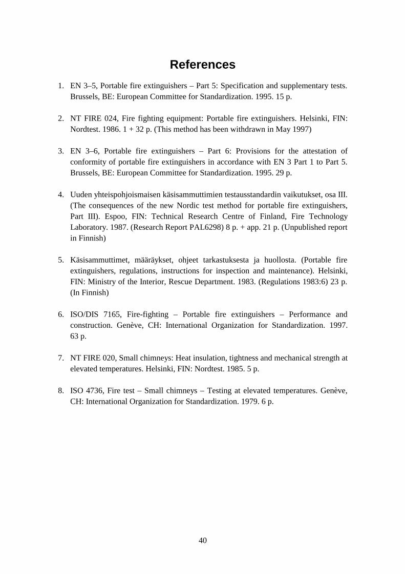
Figure 2 displays another stored pressure portable fire extinguisher which in this case isactivated with a squeeze grip lever device. These devices are most commonly used infire extinguishers with a charge of more than 3 kg, but they are also used frequently forsmaller water based and carbon dioxide extinguishers. The actuation device consists of atwo-part squeeze grip where the lower part is fixed and the upper part movable. Pressingdown the upper part of the squeeze grip opens a control valve which enables thepropellant to force the extinguishing powder to flow out through the diptube and intothe hose assembly.
Figure 2. A stored pressure portable fire extinguisher with a squeeze grip leveroperating device. No. 1 is the safety device, No. 2 the squeeze grip lever device, No. 4the control valve, No. 5 the diptube and No. 7 the hose assembly [2].
A3
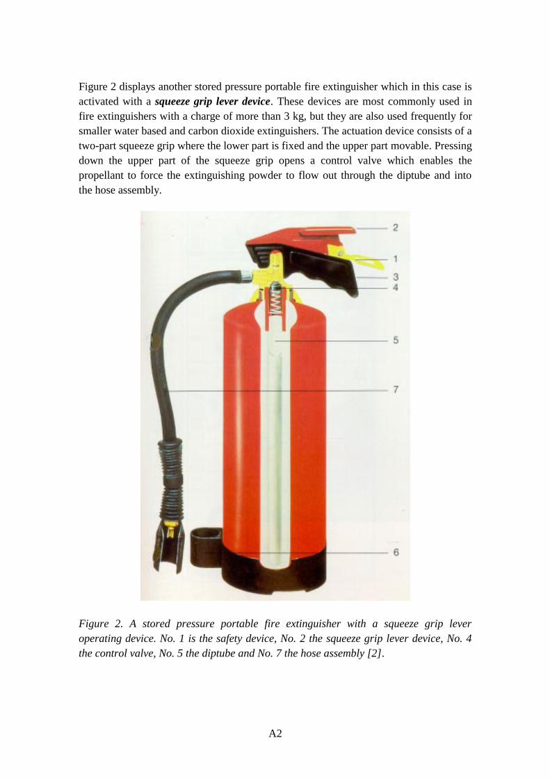
Figure 3 shows a portable fire extinguisher which is pressurised only at the moment ofoperation. This extinguisher is also activated with a squeeze grip lever device. When themovable part of the grip lever is pressed down, it will first puncture a burst disc of apropellant gas cartridge located inside the extinguisher body. This will cause thepropellant gas to flow out and pressurise the fire extinguisher. Continuing pressing ofthe movable part of the grip lever will the act on the control valve of the extinguisher asin the two previous cases with stored pressure portable fire extinguishers.
Figure 3. A portable fire extinguisher which is pressurised only at the moment ofoperation. The actuating device a squeeze grip lever operating device. No. 1 is thesafety device, No. 2 the squeeze grip lever device, No. 3 the puncture device, No. 4 theblowpipe, No. 5 the hose, No. 6 the control valve and No.8 the propellant gas cartridge[2].
.

A4
Commonly used types of safety devices
The most common safety device consists of a thin (ø 2 – 3 mm) locking pin with a pullring in one end. The upper and lower parts of a squeeze grip lever are joined togetherwith the locking pin which is pushed through two or four holes drilled in the levers. Asmall hole is drilled in the other end of the pin through which a metal wire is drawn sothat it locks the operating mechanism of the extinguisher in place. The ends of the metalwire are joined with a lead seal so that it is not possible to release the safety device or tooperate the extinguisher without breaking the seal.
In order to use the fire extinguisher, the safety device must first be released by pullingout the locking pin by the pull ring. Through this action the sealing wire will break andthe upper grip lever can be pressed down and thus open the control valve and dischargethe extinguishing media. The force required to break the sealing wire is the force whichis to be measured.
Instead of metal locking pins various ingeniously designed plastic parts may be used forthe same purpose particularly in smaller extinguishers with finger trigger actuatingdevices. In some cases the combination of locking pin, pull ring, sealing wire and sealmay be replaced by a single plastic part which will be broken and removed before theextinguisher is used.
References
1. Jauhesammutin Gloria P 2 G, P 2 GM (Powder Extinguisher Gloria P 2 G, P 2 GM).Brochure, Oy Mercantile Ab, 1997. 2 p. (In Finnish)
2. Ennakointi on turvallisuutta (Anticipation is safety). Brochure, Oy Mercantile Ab,1991. 16 p. (In Finnish)
B1
Appendix B: Photographs of the test equipment
Figure 1. General view of the test rig.
B2
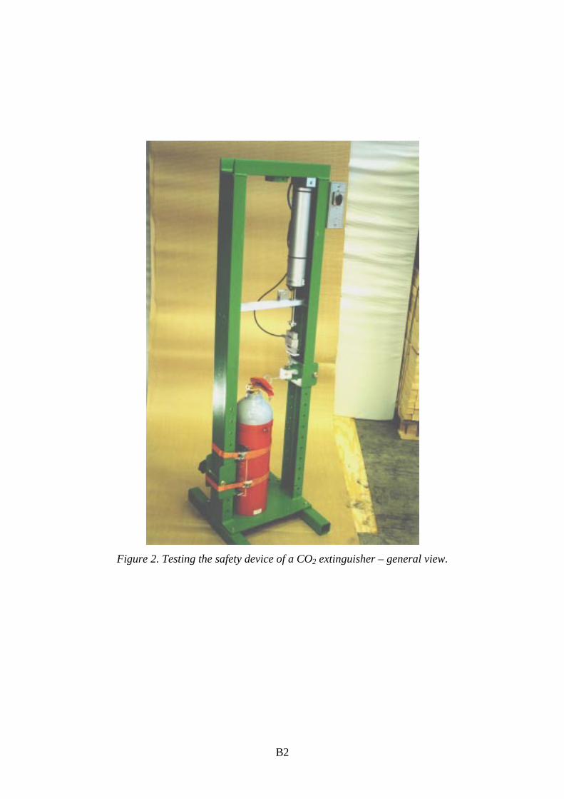
Figure 2. Testing the safety device of a CO2 extinguisher – general view.

B3
Figure 3. Testing the safety device of a CO2 extinguisher – detailed view.
B4
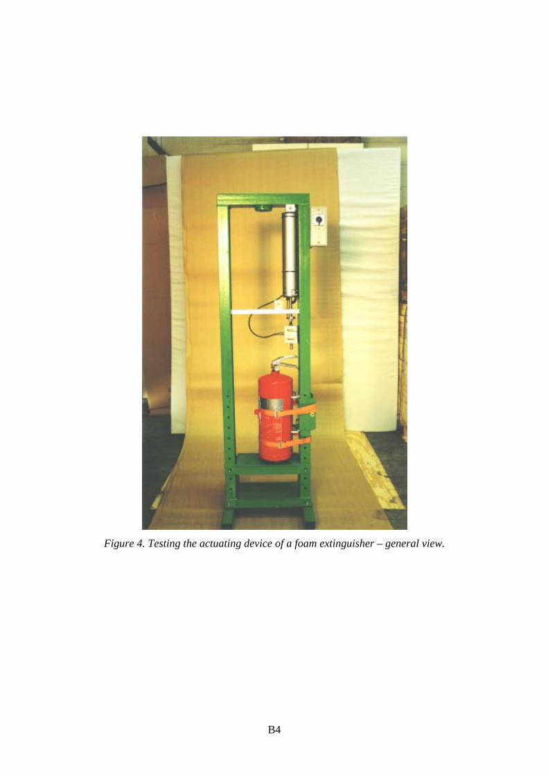
Figure 4. Testing the actuating device of a foam extinguisher – general view.
B5
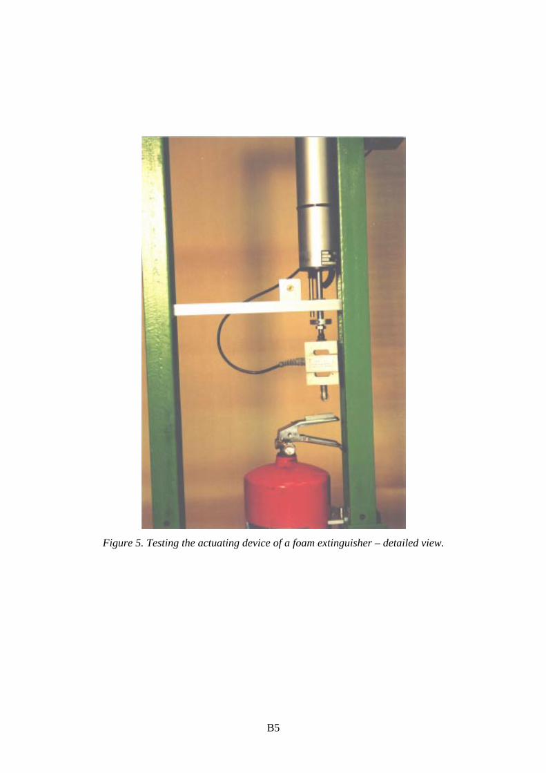
Figure 5. Testing the actuating device of a foam extinguisher – detailed view.
B6
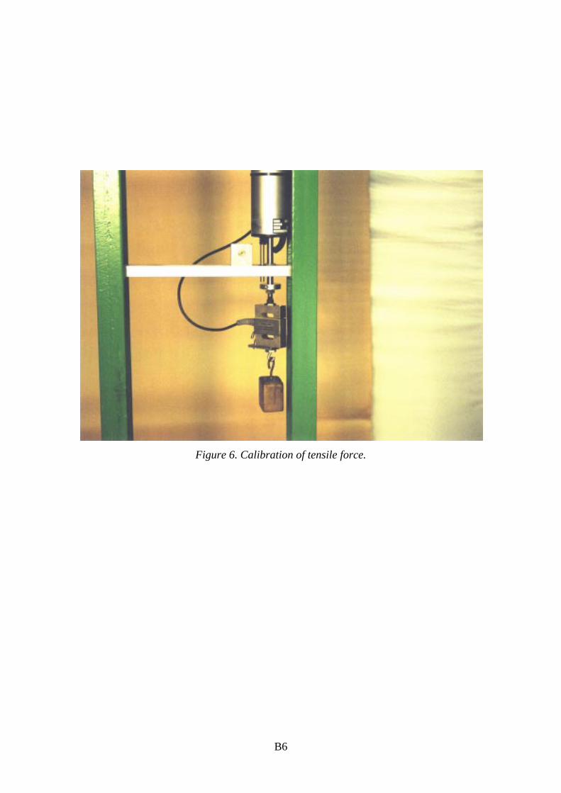
Figure 6. Calibration of tensile force.
B7
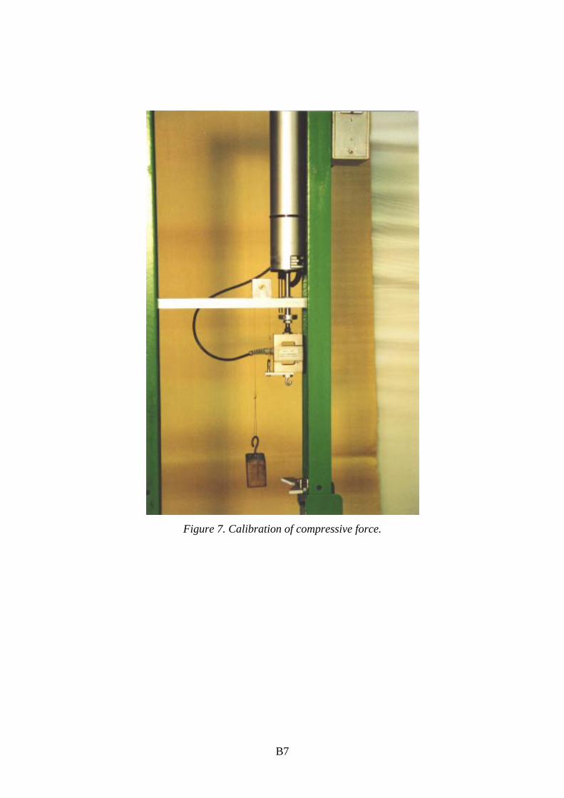
Figure 7. Calibration of compressive force.
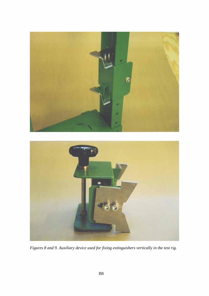
Figures 8 and 9. Auxiliary device used for fixing extinguishers vertically in the test rig.
B8
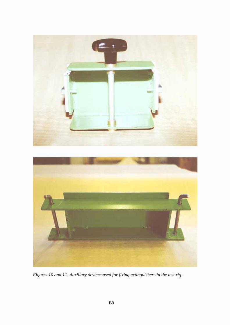
Figures 10 and 11. Auxiliary devices used for fixing extinguishers in the test rig.
B9
B10
Figure 12. Pulley device used for calibration and for testing of tensile force.
C1
Appendix C: Proposal for a new Nordtest method
Portable fire extinguishers: Force required toactivate operating devices and to release safetydevices
0. FOREWORD
The European standard series EN 3 specifies the description, characteristics andperformance requirements and test methods of portable fire extinguishers.
The methods for measuring the force required to activate the operating devices and torelease the safety devices of portable fire extinguishers are described at a general levelin the standard EN 3–5. The description may, however, lead to different interpretationsof how the measurements are to be carried out in practice. This Nordtest method, whichis to be used in conjunction with EN 3–5, describes test methods which are morespecified than those in EN 3–5. The procedures included in this Nordtest method alsomeet the demands of EN 3–5.
1. SCOPE
This Nordtest method contains test procedures for measuring the force required toactivate the operating devices and to release the safety devices of portable fireextinguishers. The procedures described here are intended to supplement thecorresponding procedures included in EN 3–5 and to eliminate any potential ambiguitiesin them.
2. FIELD OF APPLICATION
This Nordtest method is suitable for portable fire extinguishers within the scope of EN 3in which the operating device is of the finger trigger or squeeze grip lever type.
C2
Extinguishers with an operating device of the strike knob type are tested according toAnnex F of EN 3–5.
3. REFERENCES
EN 3–1:1996. Portable fire extinguishers – Part 1: Description, duration of operation,class A and B fire tests.
EN 3–2:1996. Portable fire extinguishers – Part 2: Tightness, dielectric test, tampingtest, special provisions.
EN 3–3:1994. Portable fire extinguishers – Part 3: Construction, resistance to pressure,mechanical test.
EN 3–4:1996. Portable fire extinguishers – Part 4: Charges, minimum required fire.
EN 3–5:1996. Portable fire extinguishers – Part 5: Specification and supplementarytests.
EN 3–6:1995. Portable fire extinguishers – Part 6: Provisions for the attestation ofconformity of portable fire extinguishers in accordance with EN 3 part 1 to part 5.
4. DEFINITIONS
For the purpose of this Nordtest method, the definitions given in EN 3 apply.
5. SAMPLING
The sampling is to be carried out as specified in EN 3–6.
According to EN 3–6, six extinguishers are required for these tests. Four of theextinguishers shall prior to the tests be subjected to the temperature cycle defined insection 3.1 and Annex A of EN 3–5 and two of which have been subjected to externalcorrosion conditions defined in section 5.1 and Annex H.1 of EN 3–5. Additionally onetest shall also be carried out on the operating device of an extinguisher without firstreleasing the safety device.

C3
6. TEST METHOD
6.1. Principle
Each extinguisher is in turn fixed firmly in a test rig so that its safety device or actuatingdevice is aligned and located correctly in relation to a force cylinder and load cellcombination. Depending on the actual construction of the extinguisher, either acompressive or tensile force is then exerted with the force cylinder on the safety deviceor actuating device. The force is slowly increased until the safety device is released orthe extinguisher is activated and the extinguishing media starts to discharge. Themagnitude of the exerted force is recorded continuously during this process and themaximum measured value is the one to be reported. The forces required to released thesafety device and to activate the operating device are in general measured separately.The same procedures apply to the measurements of both of these forces.
One test shall also be carried out on the operating device of an extinguisher without firstreleasing the safety device. The force to be applied in this test shall be equal to twice therespective value specified in Table 1 of EN 3–5 (this information is also included inAnnex B2 below).
6.2. Equipment
The main parts of the test equipment are: a test rig, force cylinder, load cell and datarecording equipment.
6.2.1. Test rig
Due to the widely varying design of practical extinguishers, no detailed description of atest rig suitable for every conceivable extinguisher can be given. The test rig shall,however, allow the extinguisher to be fixed firmly to the test rig with its safety oractuating device located and aligned correctly in relation to the force cylinder with theload cell. To achieve this, a metal framework with various auxiliary equipment, such asmounting brackets, straps, pulleys, wires, etc., may be used.
Annex A shows an example of a test rig which has been used for testing of several types of
commonly used extinguishers.
C4
6.2.2. Force cylinder
A force cylinder shall be used for exerting the force on the safety device or actuatingdevice of the extinguisher being tested. The force cylinder shall be capable of creating acompressive and/or tensile force of at least 500 N. The control mechanism of the forcecylinder shall be able to extend or retract the shaft of the cylinder at a rate of 10 ± 2mm/s. The force cylinder may be either of electric, pneumatic or hydraulic type.
A suitable force cylinder is for instance Dynox Type CS 50/8–300, which is used in the test
equipment shown in Annex A.
6.2.3. Load cell
A load cell capable of measuring compressive and/or tensile force up to at least 1000 Nwith an accuracy better than 0.1 % shall be fixed to the shaft of the force cylinder. Theopposite side of the force cylinder is provided with exchangeable suitable devicesneeded for transmitting the force to the extinguisher. Such auxiliary devices may be e.g.a plunger with a roller for exerting direct compressive force or a hook to which a wirecan be fixed for exerting tensile force.
The load cell shall be calibrated for both compressive and tensile prior to each testseries. A suitable method is to use a series of weights of known mass which aresuspended from the load cell. The mass of the weights should be in the range 0–5 kg.The force cell shall be operating during the calibration.
A suitable load cell is for instance Tedea Ltd, Model 606–S–100, which is used in the test
equipment shown in Annex A. This load cell contains a bridge of strain gauges.
6.2.4. Data recording equipment
The output from the load cell shall be recorded by an analogue or preferably by a digitaldevice. If a digital device is used, it shall be capable of taking readings at a frequency ofat least 100 s-1.
A suitable data recording equipment consists for instance of a data acquisition device Data
Translation Inc, Model DT2805, which is controlled by a computer. The computer is also used
for processing the data. This is the set-up used in the test equipment shown in Annex A.
C5
6.3. Testing environment
The tests shall be carried out indoors at ordinary ambient conditions.
6.4. Pre-conditioning of test samples
Four of the six extinguishers shall prior to the tests be subjected to the temperature cycledefined in section 3.1 and Annex A of EN 3–5 and two of which have been subjected toexternal corrosion conditions defined in section 5.1 and Annex H.1 of EN 3–5.
6.5. Test procedure and data processing
6.5.1. Fixing and aligning the extinguisher
The extinguisher shall be fixed firmly with the aid of suitable auxiliary devices in thetest rig and aligned so the force exerted by the force cylinder is directed perpendicularlyat the normal point where the force in practice will be used in order to release the safetydevice or to activate the operating device of the extinguisher.
In most cases the exact point where the force is to be directed is self-evident. However,for actuating devices of the squeeze grip lever type, this point shall be located at adistance measured from the hinge of the lever, which is between 0.7 and 0.8 times thefree length of the movable lever. The free length of the lever is measured along theupper side of the lever from the point where the valve actuator of the extinguisherinitially contacts the lever to the free end of the lever.
If the test is to be carried out using tensile force, suitable auxiliary devices, such aspulleys and wires, shall be mounted between the extinguisher and the load cell forcorrectly aligning and transmitting the force.
6.5.2. Measurement of the force
The data recording device shall be started at least 60 s before the force cylinder isactivated. The activation of the force cylinder causes the shaft of the cylinder to eitherextend or retract at a constant rate and exert a force on the safety device or actuatingdevice of the extinguisher. The application of force is continued until the safety deviceis unambiguously released or the discharge of the extinguishing media starts. The datarecording device shall be stopped after the application of force has ended.

C6
When testing actuating devices of fire extinguishers which are pressurised only at themoment of operation, the application of force shall be interrupted for 5 s after the burstdisc of the propellant gas cartridge has been punctured.
6.5.3. Data processing
The data recording device records continuously the exerted tensile or compressive forceas a function of time. The maximum measured force is the force required to release thesafety device or to activate the operating device of the particular sample of theextinguisher being tested. Figure 1 shows a typical example of a time vs. force curve forthe safety device of a CO2 extinguisher. Figure 2 shows a similar curve for the operatingdevice of a foam extinguisher.
-5
0
5
10
15
20
25
30
0 0.5 1 1.5 2
Time (s)
For
ce (
N)
Figure 1. Example of the measured force during a test on the safety device of a CO2
extinguisher.
0
10
20
30
40
50
60
70
0 0.5 1 1.5 2 2.5 3Time (s)
For
ce (
N)
Figure 2. Example of the measured force during a test on the operating device of a foamextinguisher.
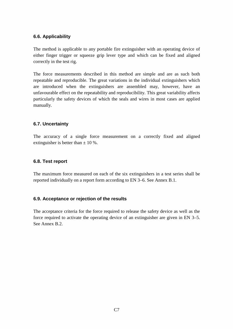
C7
6.6. Applicability
The method is applicable to any portable fire extinguisher with an operating device ofeither finger trigger or squeeze grip lever type and which can be fixed and alignedcorrectly in the test rig.
The force measurements described in this method are simple and are as such bothrepeatable and reproducible. The great variations in the individual extinguishers whichare introduced when the extinguishers are assembled may, however, have anunfavourable effect on the repeatability and reproducibility. This great variability affectsparticularly the safety devices of which the seals and wires in most cases are appliedmanually.
6.7. Uncertainty
The accuracy of a single force measurement on a correctly fixed and alignedextinguisher is better than ± 10 %.
6.8. Test report
The maximum force measured on each of the six extinguishers in a test series shall bereported individually on a report form according to EN 3–6. See Annex B.1.
6.9. Acceptance or rejection of the results
The acceptance criteria for the force required to release the safety device as well as theforce required to activate the operating device of an extinguisher are given in EN 3–5.See Annex B.2.
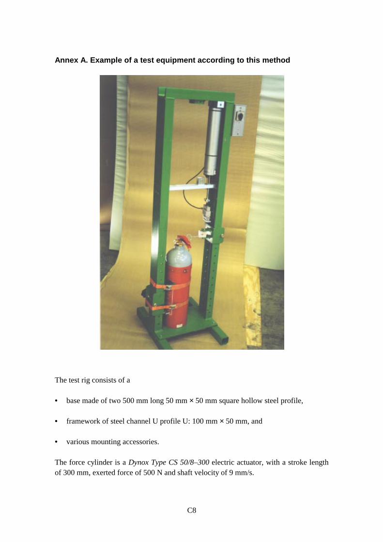
C8
Annex A. Example of a test equipment according to this method
The test rig consists of a
• base made of two 500 mm long 50 mm × 50 mm square hollow steel profile,
• framework of steel channel U profile U: 100 mm × 50 mm, and
• various mounting accessories.
The force cylinder is a Dynox Type CS 50/8–300 electric actuator, with a stroke lengthof 300 mm, exerted force of 500 N and shaft velocity of 9 mm/s.

C9
The load cell is a Tedea Ltd, Model 606–S–100 based on a bridge of strain gauges andwith a maximum capacity of 100 kg.
The data recording equipment (not shown above) consists of a Data Translation, Inc,Model DT2805 data acquisition board mounted in a PC type computer and using aLabtech Notebook for Windows V. 9.02 controller program.
A dust collecting cyclone for tests on powder extinguishers (not shown above).
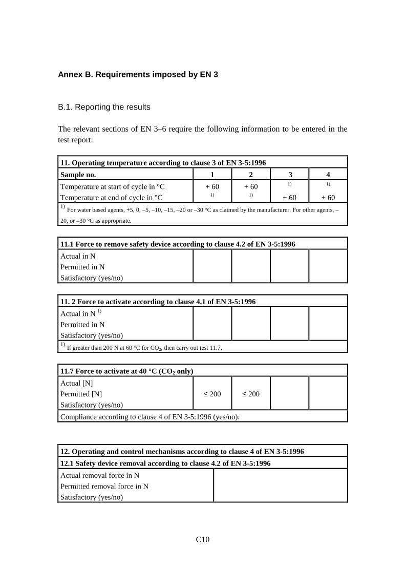
C10
Annex B. Requirements imposed by EN 3
B.1. Reporting the results
The relevant sections of EN 3–6 require the following information to be entered in thetest report:
11. Operating temperature according to clause 3 of EN 3-5:1996
Sample no. 1 2 3 4
Temperature at start of cycle in °C
Temperature at end of cycle in °C
+ 60
1)
+ 60
1)
1)
+ 60
1)
+ 60
1) For water based agents, +5, 0, –5, –10, –15, –20 or –30 °C as claimed by the manufacturer. For other agents, –
20, or –30 °C as appropriate.
11.1 Force to remove safety device according to clause 4.2 of EN 3-5:1996
Actual in N
Permitted in N
Satisfactory (yes/no)
11. 2 Force to activate according to clause 4.1 of EN 3-5:1996
Actual in N 1)
Permitted in N
Satisfactory (yes/no)
1) If greater than 200 N at 60 °C for CO2, then carry out test 11.7.
11.7 Force to activate at 40 °C (CO2 only)
Actual [N]
Permitted [N]
Satisfactory (yes/no)
≤ 200
≤ 200
Compliance according to clause 4 of EN 3-5:1996 (yes/no):
12. Operating and control mechanisms according to clause 4 of EN 3-5:1996
12.1 Safety device removal according to clause 4.2 of EN 3-5:1996
Actual removal force in N
Permitted removal force in N
Satisfactory (yes/no)
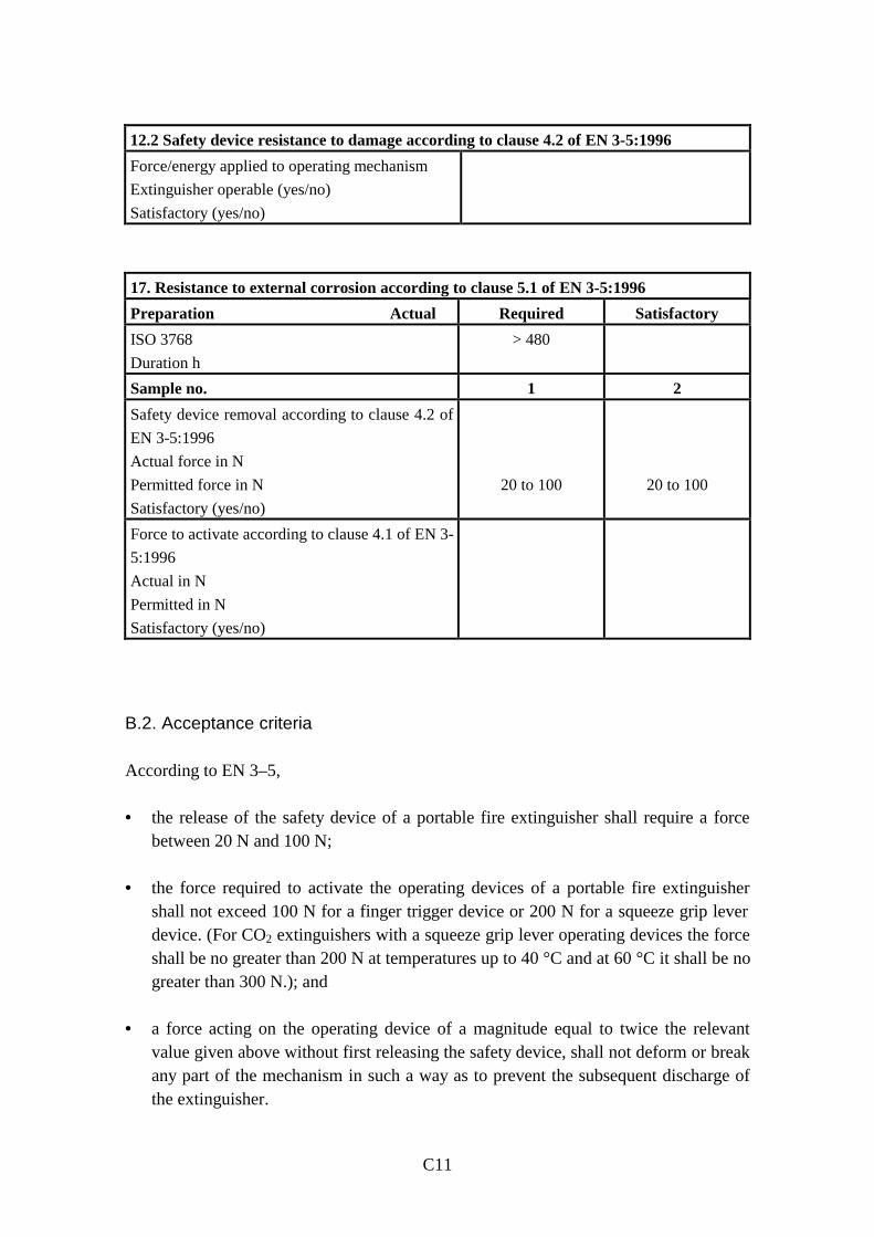
C11
12.2 Safety device resistance to damage according to clause 4.2 of EN 3-5:1996
Force/energy applied to operating mechanism
Extinguisher operable (yes/no)
Satisfactory (yes/no)
17. Resistance to external corrosion according to clause 5.1 of EN 3-5:1996
Preparation Actual Required Satisfactory
ISO 3768
Duration h
> 480
Sample no. 1 2
Safety device removal according to clause 4.2 of
EN 3-5:1996
Actual force in N
Permitted force in N
Satisfactory (yes/no)
20 to 100
20 to 100
Force to activate according to clause 4.1 of EN 3-
5:1996
Actual in N
Permitted in N
Satisfactory (yes/no)
B.2. Acceptance criteria
According to EN 3–5,
• the release of the safety device of a portable fire extinguisher shall require a forcebetween 20 N and 100 N;
• the force required to activate the operating devices of a portable fire extinguishershall not exceed 100 N for a finger trigger device or 200 N for a squeeze grip leverdevice. (For CO2 extinguishers with a squeeze grip lever operating devices the forceshall be no greater than 200 N at temperatures up to 40 °C and at 60 °C it shall be nogreater than 300 N.); and
• a force acting on the operating device of a magnitude equal to twice the relevantvalue given above without first releasing the safety device, shall not deform or breakany part of the mechanism in such a way as to prevent the subsequent discharge ofthe extinguisher.