Embed Size (px)
Citation preview

The Resistance Committee
Final Report
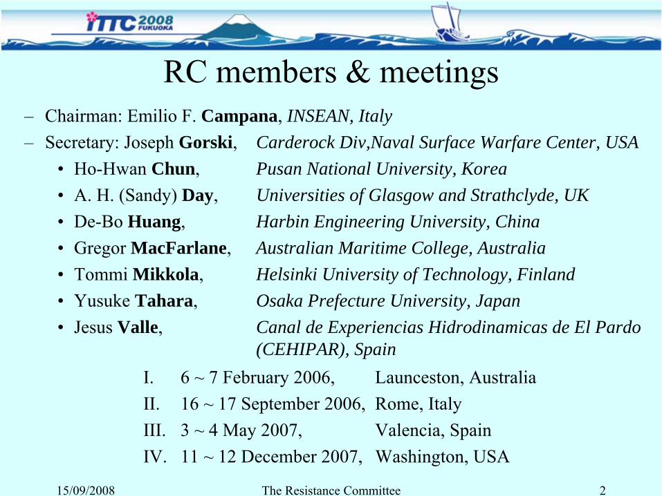
RC members & meetings–
Chairman: Emilio F. Campana, INSEAN, Italy
–
Secretary: Joseph Gorski, Carderock Div,Naval Surface Warfare Center, USA•
Ho-Hwan Chun, Pusan National University, Korea
•
A. H. (Sandy) Day, Universities of Glasgow and Strathclyde, UK•
De-Bo Huang, Harbin Engineering University, China
•
Gregor MacFarlane, Australian Maritime College, Australia•
Tommi Mikkola, Helsinki University of Technology, Finland
•
Yusuke Tahara, Osaka Prefecture University, Japan•
Jesus Valle, Canal de Experiencias Hidrodinamicas de El Pardo
(CEHIPAR), SpainI.
6 ~ 7 February 2006, Launceston, Australia
II.
16 ~ 17 September 2006, Rome, ItalyIII.
3 ~ 4 May 2007, Valencia, Spain
IV.
11 ~ 12 December 2007, Washington, USA
15/09/2008 The Resistance Committee 2
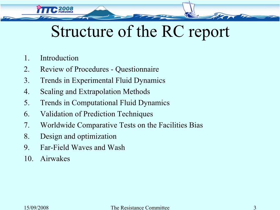
Structure of the RC report1.
Introduction
2.
Review of Procedures -
Questionnaire 3.
Trends in Experimental Fluid Dynamics
4.
Scaling and Extrapolation Methods5.
Trends in Computational Fluid Dynamics
6.
Validation of Prediction Techniques7.
Worldwide Comparative Tests on the Facilities Bias
8.
Design and optimization9.
Far-Field Waves and Wash
10.
Airwakes
15/09/2008 The Resistance Committee 3
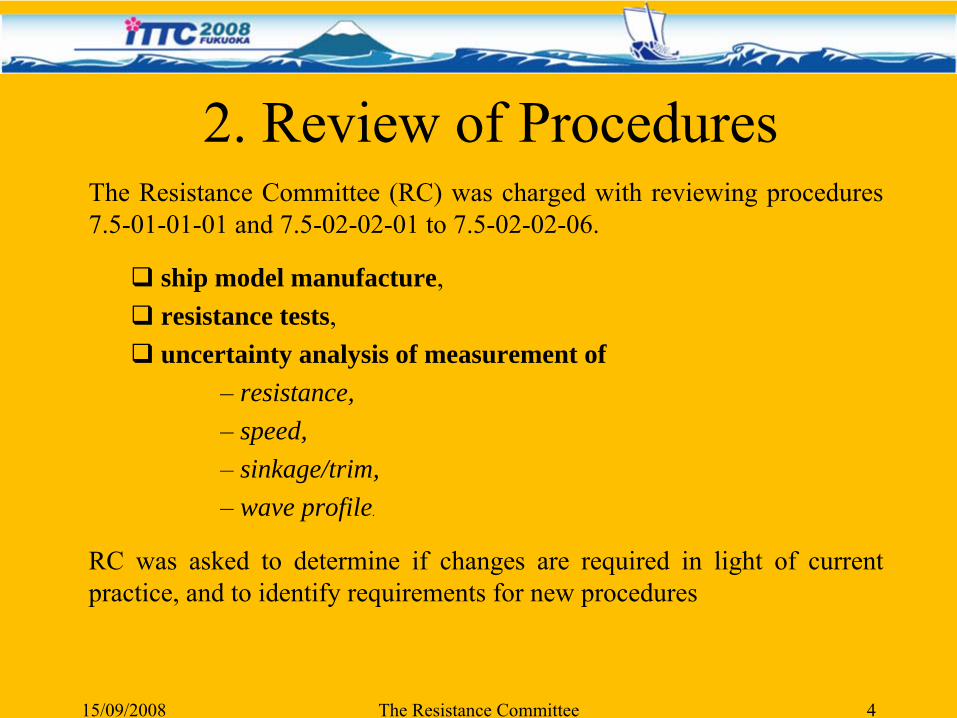
2. Review of ProceduresThe Resistance Committee (RC) was charged with reviewing procedures 7.5-01-01-01 and 7.5-02-02-01 to 7.5-02-02-06.
ship model manufacture, resistance tests, uncertainty analysis of measurement of
– resistance, – speed, – sinkage/trim, – wave profile.
RC was asked to determine if changes are required in light of current practice, and to identify requirements for new procedures
15/09/2008 The Resistance Committee 4
Questionnaire: Resistance Test ProcedureIn some parts of the procedures, improvements could be made in wording and notation; however some areas also offered the potential for technical improvements
The RC prepared a questionnaire on issues considered by the RC to offer potential for improvement. This addressed three areas:
– Turbulence Stimulation and Scaling; – Speed Measurement, – Model Installation.
The questionnaire was circulated by e-mail to all ITTC facilities. 25 facilities replied to the questionnaire; 11 from Europe, 11 from Asia and Australia and 3 from the Americas.
The results of the questionnaire were used to inform the proposed changes to the procedures
15/09/2008 The Resistance Committee 5
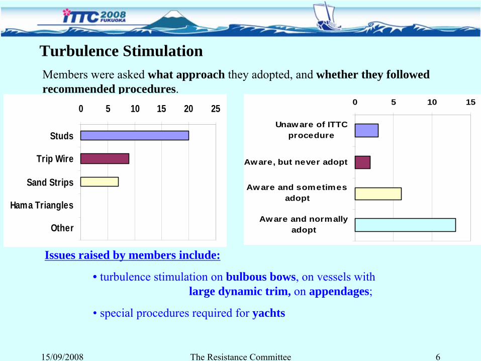
Members were asked what approach they adopted, and whether they followed recommended procedures.
0 5 10 15 20 25
Studs
Trip Wire
Sand Strips
Hama Triangles
Other
0 5 10 15
Unaware of ITTCprocedure
Aware, but never adopt
Aware and sometimesadopt
Aware and normallyadopt
Issues raised by members include:
• turbulence stimulation on bulbous bows, on vessels with large dynamic trim, on appendages;
• special procedures required for yachts
Turbulence Stimulation
15/09/2008 The Resistance Committee 6
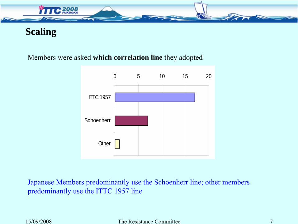
Members were asked which correlation line they adopted
Japanese Members predominantly use the Schoenherr line; other members predominantly use the ITTC 1957 line
Scaling
0 5 10 15 20
ITTC 1957
Schoenherr
Other
15/09/2008 The Resistance Committee 7
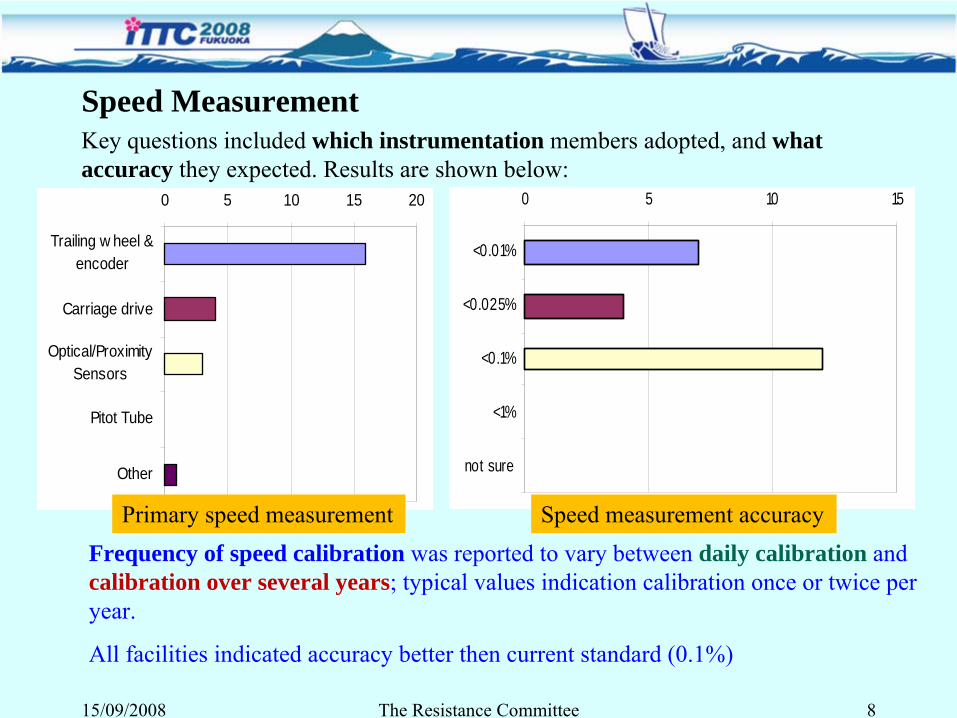
Key questions included which instrumentation members adopted, and what accuracy they expected. Results are shown below:
Frequency of speed calibration was reported to vary between daily calibration and calibration over several years; typical values indication calibration once or twice per year.
All facilities indicated accuracy better then current standard (0.1%)
Speed Measurement
0 5 10 15 20
Trailing w heel &encoder
Carriage drive
Optical/ProximitySensors
Pitot Tube
Other
0 5 10 15
<0.01%
<0.025%
<0.1%
<1%
not sure
15/09/2008 The Resistance Committee 8
Primary speed measurement Speed measurement accuracy
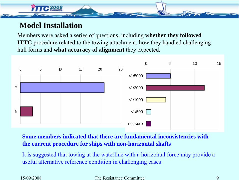
Members were asked a series of questions, including whether they followed ITTC procedure related to the towing attachment, how they handled challenging hull forms and what accuracy of alignment they expected.
Some members indicated that there are fundamental inconsistencies with the current procedure for ships with non-horizontal shafts
It is suggested that towing at the waterline with a horizontal force may provide a useful alternative reference condition in challenging cases
Model Installation
0 5 10 15 20 25
Y
N
0 5 10 15
<1/5000
<1/2000
<1/1000
<1/500
not sure
15/09/2008 The Resistance Committee 9
7.5-01-01-01: Model Manufacture: Ship models
There were few revisions of substance proposed. A number of minor changes were suggested:
•
A number of modifications and additions to detailed specifications of parameters such as error tolerances were suggested.
•
A few minor recommendations were added for completeness in line with common practice
•
Some clarifications were made (in particular with regard to ballasting procedure) to reduce scope for errors of interpretation
•
Typographical errors were corrected.
Changes to procedures
15/09/2008 The Resistance Committee 10
7.5-02-02-01: Testing and Extrapolation Methods: Resistance
A number of revisions were proposed. These address:
•
Clarification of range of vessel types
•
Additional recommendations regarding model installation and alignment
•
Clarifications and additions to lists of “typical” instruments used for various measurement tasks
•
Record-keeping of signal conditioning and data acquisition configuration
•
Practice related to zeroing of instruments
•
Practice related to averaging oscillatory variation of wave resistance
•
Choice of sampling rates for data acquisition systems
•
Use of Prohaska test for vessels with transom sterns
15/09/2008 The Resistance Committee 11
Changes to procedures
New Facilities
As part of the questionnaire, members were asked what major new facilities they had commissioned during the period between the 24th
and 25th
ITTC.Three replies were received:
Australian Maritime College: A new cavitation tunnel is being commissioned during 2008. The tunnel is of the vertical plane, closed recirculating type. The working section maximum velocity is 12m/s, and the maximum and minimum absolute pressures are 400kPa, 4kPa. The cavitation number range is from 0.07 to 5.5
CEHIPAR have installed a numerically-controlled five-axis milling machine with capacity to produce models up to 10950 mm long, 2500 mm wide and
1200 mm
high using a range of materials including aluminium, bronze, wood, paraffin wax, PVC, polystyrenes, polyurethanes
Universities of Glasgow and Strathclyde A new four-paddle absorbing wavemaker was installed which can generate periodic waves from 0.2Hz -2Hz. Periodic waves over 600mm in height can be generated; single breaking waves can
be generated
up to around 1000mm in height.
15/09/2008 The Resistance Committee 12
Review for new techniques and trends in EFD
• New and advanced techniques in hydrodynamic experiments
• Wake and pressure measurements• Wave breaking and wave profile measurements • Full scale tests • Drag reduction
15/09/2008 The Resistance Committee 13
3. Trends in Experimental Fluid Dynamics
New and Advanced Techniques in Hydrodynamic Experiments
New developments in hydrodynamic experiments and measurement techniques in towing tanks, water channels and wind tunnelsEFD progress is closely related with the improvements of optical techniques such as:
• Particle Image Velocimetry (PIV), • Particle Tracking Velocimetry (PTV), • Laser Doppler Velocimetry (LDV), • Laser Induced Fluorescence (LIF)
and other techniques such as Acoustic Doppler Velocimetry (ADV)
15/09/2008 The Resistance Committee 14
Wake and PressureWake and turbulent flow measurement behind a structure using PIV (Paik et al., 2007 and Wosnik & Arndt, 2006)
Application of the stereoscopic PIV system to investigate flow structures behind cylinder (Perrin et al., 2007) and of a prototype waterjet model (Jung et al., 2006)
Pressure Sensitive Paint (PSP) in wind tunnel-
Dynamic and static surface pressure on a square cylinder measured by PSP (McGraw et al., 2006)
-
Evaluation four PSP formulation in slow speeds wind tunnel (Lee and Kang, 2006)
15/09/2008 The Resistance Committee 15
Wave Breaking and Wave Profile MeasurementBow waves were measured by laser imaging technique (Karion et al., 2004)
Model and Full scale reconstruction of the near and far field wave pattern of a given hull, obtained by a combination of various instruments (Rice et al., 2004)
PIV technique was employed to measure the velocity field near the floating structure and to understand the eddy making damping and turbulent properties (Jung et al., 2005 and Jung et al., 2006)
Flow field under the plunging wave breaking was obtained by LDV and PIV (Stern et al., 2006)
Some limitations of PIV and PTV (light saturation on bubbles) can be overcome by the combination with LIF
15/09/2008 The Resistance Committee 16
Full Scale Tests
Full scale measurement of spray droplets from a breaking bow wave was carried out by using a high speed digital video camera (Sur and Chevalier, 2004)
Velocity measurement in wave field was performed at full scaleusing ship-mounted LDV during sea trials (Starke et al., 2006)
Free surface and bubble dynamics around a ship were measured by integrating 11 measurement systems and instruments (Fu et al., 2006)
LIDAR (LIght Detection And Ranging) was employed to obtain the full scale wave field around Sea Fighter (Terrill and Taylor, 2007)
15/09/2008 The Resistance Committee 17
Drag ReductionMicrobubble InjectionVisualization of the interaction b/w the flow and microbubbles using PIV combined with Shadow Image Technique (Kitagawa et al. 2005)
Polymer InjectionDR by polymer injection (Baik et al., 2005, and Jovanović
et al.,
2006) and with combined injection of gas and polymer (Deutsch et al., 2006)
Compliant CoatingCollaborative effort of USA, Russia and UK for undersea application (Bandyopadhyay et al., 2005)
Active Control
15/09/2008 The Resistance Committee 18
4. Scaling and Extrapolation Method
The 25th
ITTC RC conducted an analyticalstudy on friction lines
•
Overview of Methods •
Comparison of the Results
15/09/2008 The Resistance Committee 19
Friction Lines used in TT activityThe speed-power prediction is one of the most important functions of towing-
tank facilities.
During the extrapolation to ship-scale resistance (for power estimation) friction line plays a major role.
Empirical equations for frictional resistance, such as Schoenherr’s formula (Schoenherr, 1932) and the ITTC’57 correlation line, are used.
•Recent reliable measurements of friction resistance for a flat plate indicate that Schoenherr’s formula overestimates the local frictional coefficient by 2-
3% even in the range of model scale Reynolds number.
•Grigson (1993) and Katsui et al. (2005) proposed methods to predict friction resistance for model-
through ship-scale Reynolds numbers, by solving the
momentum integral equation.
15/09/2008 The Resistance Committee 20
•
Both methods are based on the solution of the momentum integral equations and Coles’
wall-wake law.
•
Major differences between Katsui et al. (2005) and Grigson (1993) :–
Recent experimental results (Osaka et al., 1993) are considered;
–
More exact form of the differential equations is solved;–
Definition of the wake parameter;
–
The derivative of the wake parameter is included in the calculation.
15/09/2008 The Resistance Committee 21
15/09/2008 The Resistance Committee 22
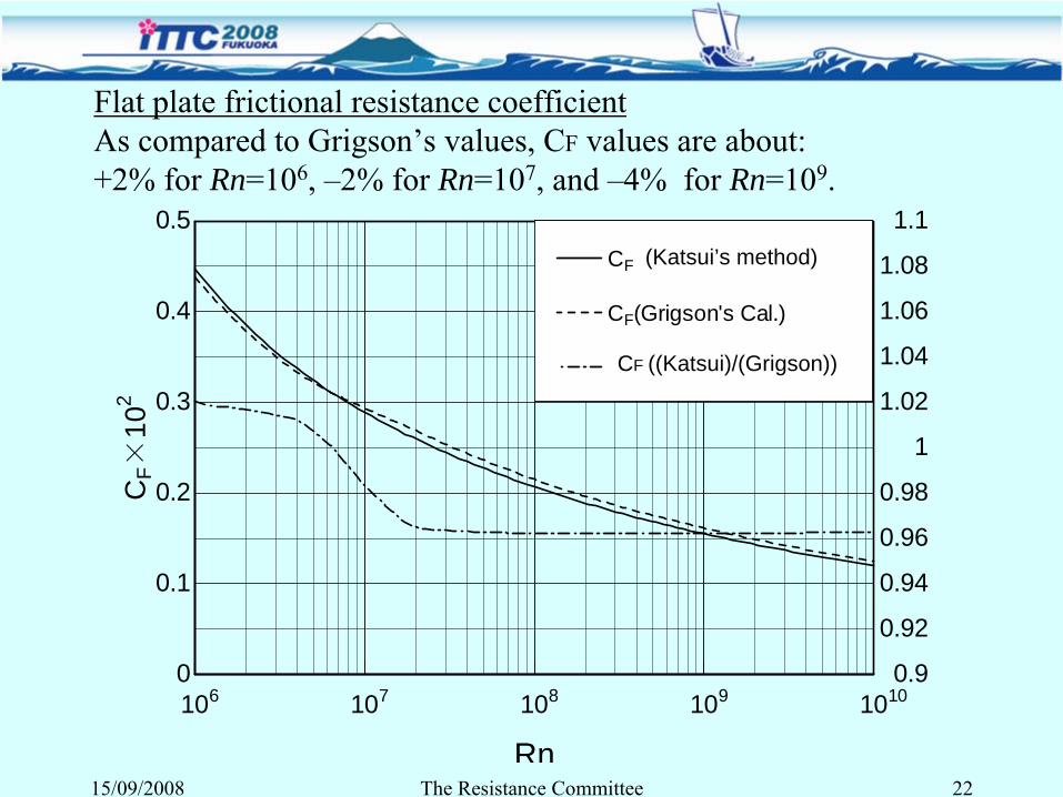
Flat plate frictional resistance coefficientAs compared to Grigson’s values, CF
values are about:+2% for Rn=106, –2% for Rn=107, and –4% for Rn=109.
106 107 108 109 10100
0.1
0.2
0.3
0.4
0.5
Rn
CF(Present method)
CF(Grigson's Cal.)
CF×
102
0.9
0.92
0.94
0.96
0.98
1
1.02
1.04
1.06
1.08
1.1
CF(present)/CF(Grigson))
(Katsui’s method)
CF ((Katsui)/(Grigson))
15/09/2008 The Resistance Committee 23
106 107 108 109 10100
0.1
0.2
0.3
0.4
0.5
Rn
CF(Present method) CF(Schoenherr's formula.)
CF×
102
CF(ITTC '57) CF(Huges' formula)
0.8
0.84
0.88
0.92
0.96
1
1.04
1.08
1.12
1.16
1.2
CF(present)/CF(Schoenherr) CF(present)/CF(ITTC) CF(present)/CF(Huges)
CF(Katsui) / CF(Schoenherr)
CF(Katsui) / CF(ITTC)
CF(Katsui) / CF(Hughes)
CF (Katsui)
CF (Schoenherr)
CF (ITTC)
CF (Hughes)
Summary•
The 25th
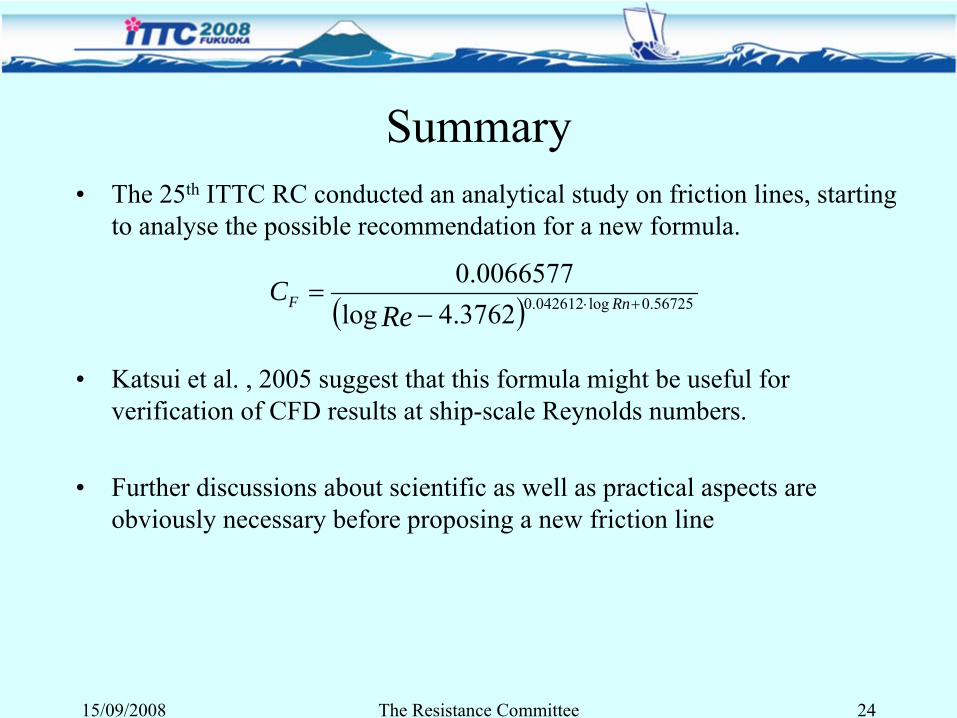
ITTC RC conducted an analytical study on friction lines, starting to analyse the possible recommendation for a new formula.
•
Katsui et al. , 2005 suggest that this formula might be useful for verification of CFD results at ship-scale Reynolds numbers.
•
Further discussions about scientific as well as practical aspects are obviously necessary before proposing a new friction line
15/09/2008 The Resistance Committee 24
( ) 56725.0log042612.03762.4log0066577.0
+⋅−= RnF Rn
CRe
5. Trends in Computational Fluid Dynamics
•
Practical Applications of CFD•
Progress in Viscous Flow Calculation Methods
•
New Applications
15/09/2008 The Resistance Committee 25
Practical Applications of CFD•
Inviscid methods still heavily used–
New Neumann-Michell consistent linear potential flow model proposed by Noblesse and Yang (2006) for slender mono-
and
multihulls
•
RANS model scale calculations–
Large amount of literature for many hull forms: e.g. Athena blind test case (Wilson et al., 2006)
–
Increasingly sophisticated with actual geometry: appendages, bilge keels, shafts, struts, propulsors
•
RANS full-scale calculations–
Use of wall functions, surface roughness can be included
–
Becoming nearly as routine for realistic configurations as model
scale predictions
–
Limited experimental data for comparison (EFFORT UE program)
•
More groups able to directly predict sinkage and trim
15/09/2008 The Resistance Committee 26
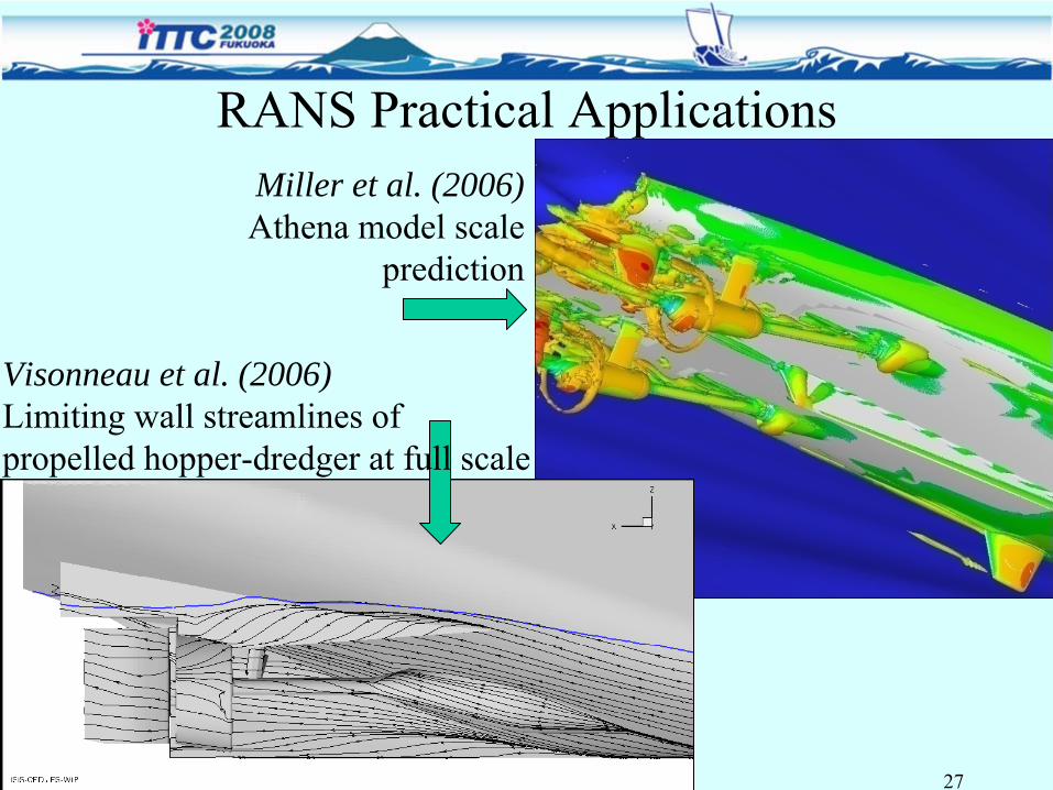
RANS Practical ApplicationsMiller et al. (2006) Athena model scale
prediction
15/09/2008 The Resistance Committee 27
Visonneau et al. (2006)Limiting wall streamlines of propelled hopper-dredger at full scale
Progress in Viscous Methods•
Continuous evolution of grids and gridding techniques–
Structured grids most heavily used
•
Good for bare hulls and some complicated geometries•
Oversets being used more often for complicated geometries
–
Unstructured grids•
Hexahedral, tetrahedral, and polyhedral
•
Tetrahedral and polyhedral need prism layers for boundary layer accuracy
–
Cartesian being used with immersed boundary methods•
Gridding is trivial (as for Panel codes)
•
Boundary layer prediction still problematic
15/09/2008 The Resistance Committee 28
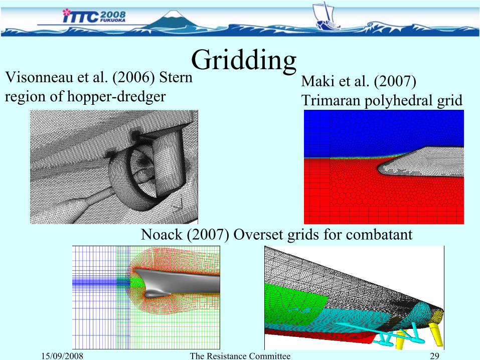
GriddingVisonneau et al. (2006) Stern region of hopper-dredger
Maki et al. (2007) Trimaran polyhedral grid
Noack (2007) Overset grids for combatant
15/09/2008 The Resistance Committee 29
Progress in Viscous Methods•
Free surface treatment–
Capturing methods have become routine (Volume of Fluid and Level Set (one-phase and two-phases)) and used by the majority of groups
–
Can numerically handle very complex free surface
•
Turbulence modeling–
Largely one-
and two-equations models in practice
–
Reynolds stress models by some groups for flow details–
Large Eddy Simulations (LES) and Detached Eddy Simulation (DES) seeing more use, but still limited
15/09/2008 The Resistance Committee 30
New Applications•
Propulsor/Hull Interaction–
Actuator disk models
–
Lifting surface/panel methods–
Full rotating propeller
•
Drag Reduction–
Microbubble and polymer effects modeled
–
Mostly restricted to simple flows and modeling issues •
High Speed Vessels–
High Froude number
–
Catamarans, trimarans, slender monohulls
15/09/2008 The Resistance Committee 31
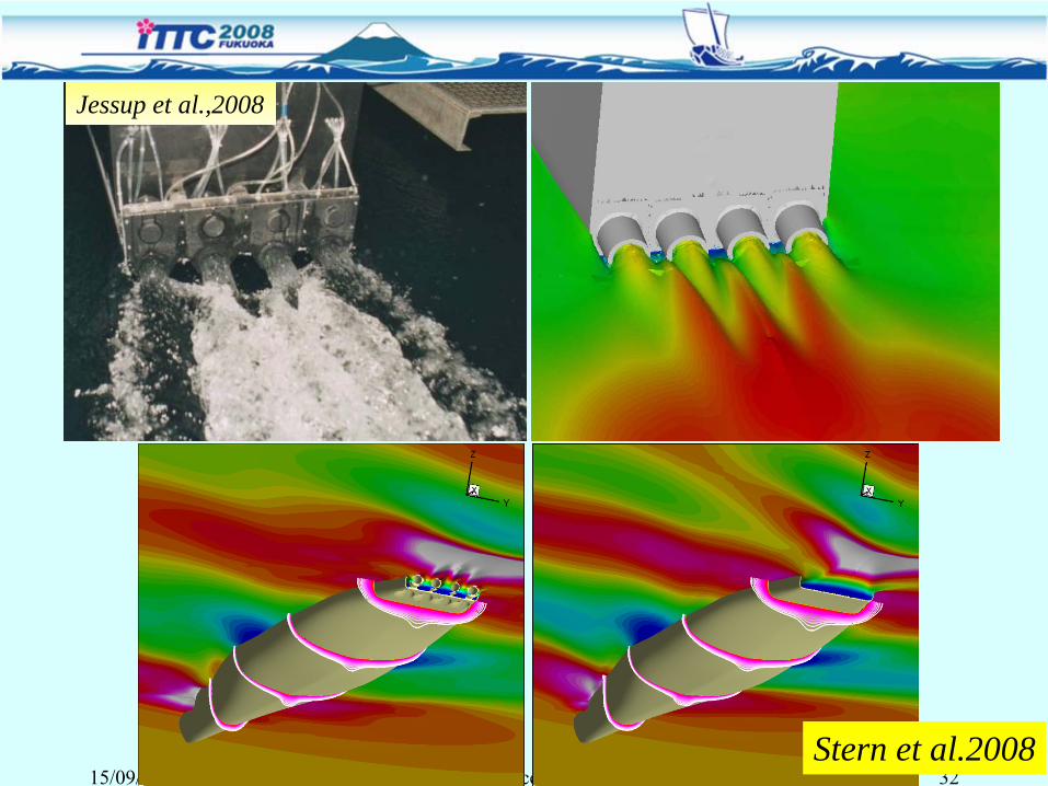
15/09/2008 The Resistance Committee 32Stern et al.2008
Jessup et al.,2008
Summary•
CFD tends to unify most of the ITTC fields of interest: resistance, seakeeping, manoeuvring of fully
appended ships•
Increasingly more useful to many groups–
Many good codes with many groups able to use the codes
–
Inroads to the design process being made–
RANS having a larger role for viscous flow study
–
Realistic geometries at model and full scale–
Expected to have larger role in the future with increasing experience and computer power
•
Still not the confidence in CFD that many have with experiments.
15/09/2008 The Resistance Committee 33
6. Validation of prediction techniques•
The report reviews recent activities in the field of Verification and Validation (V&V) considered to be of significance for the members of ITTC.
•
Different aspects of V&V have been summarised in a number of papers, including issues related to achieving consensus on V&V (Oberkampf et al., 2004, Roy, 2005, Stern et al., 2006)
15/09/2008 The Resistance Committee 34
V&V studies•
Still very few systematic V&V studies in the field
•
The ITTC recommended procedure has been used for the V&V of resistance and velocities, propeller thrust and torque as well as roll decay (Visonneau et al., 2006, Stern et al. 2006a, Di Mascio et al. 2007, Kim et al., 2006)
•
Toxopeus (2006) has used an alternative least squares based Grid Convergence Index for V&V of drift forces
•
Werner (2006) has compared the performance of three different uncertainty estimation methods, including the ITTC recommended procedure, using an analytical BL-solution
•
An extension of V&V, quantitative code certification, has been studied by Stern et al. (2006c) using the Gothenburg 2000 data
15/09/2008 The Resistance Committee 35
Iterative convergence•
Most studies deal with grid and temporal convergence
•
However, some studies published on the influence of incomplete iterative convergence (often negligible compared to other sources Wilson et al., 2006, Di Mascio et al., 2007) . Procedure developed for quantitative estimation of iterative error (Eca and Hoekstra, 2006)
Method of Manufactured Solutions (MMS) •
MMS has become an established tool for code verification with some exhaustive examples (Roy, 2005, Salari and Knupp, 2000)
•
Problems with the setting up of manufactured solutions in some cases, due to the existence of damping and blending functions (Eca and Hoekstra, 2006)
15/09/2008 The Resistance Committee 36
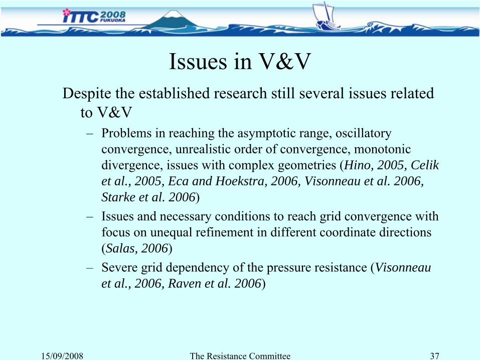
Issues in V&VDespite the established research still several issues related
to V&V–
Problems in reaching the asymptotic range, oscillatory convergence, unrealistic order of convergence, monotonic divergence, issues with complex geometries (Hino, 2005, Celik et al., 2005, Eca and Hoekstra, 2006, Visonneau et al. 2006, Starke et al. 2006)
–
Issues and necessary conditions to reach grid convergence with focus on unequal refinement in different coordinate directions (Salas, 2006)
–
Severe grid dependency of the pressure resistance (Visonneau et al., 2006, Raven et al. 2006)
15/09/2008 The Resistance Committee 37
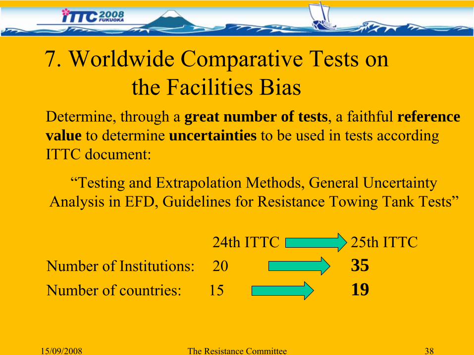
Determine, through a great number of tests, a faithful reference value to determine uncertainties to be used in tests according ITTC document:
“Testing and Extrapolation Methods, General Uncertainty Analysis in EFD, Guidelines for Resistance Towing Tank Tests”
7. Worldwide Comparative Tests on the Facilities Bias
15/09/2008 The Resistance Committee 38
24th ITTC 25th ITTCNumber of Institutions: 20 35Number of countries: 15 19
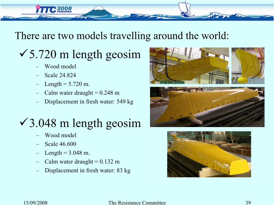
There are two models travelling around the world:
5.720 m length geosim–
Wood model–
Scale 24.824–
Length = 5.720 m.–
Calm water draught = 0.248 m–
Displacement in fresh water: 549 kg
3.048 m length geosim–
Wood model–
Scale 46.600–
Length = 3.048 m.–
Calm water draught = 0.132 m–
Displacement in fresh water: 83 kg
15/09/2008 The Resistance Committee 39
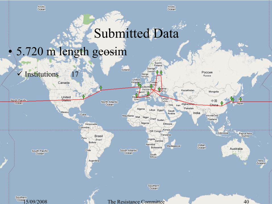
Submitted Data•
5.720 m length geosim
Institutions 17
15/09/2008 The Resistance Committee 40
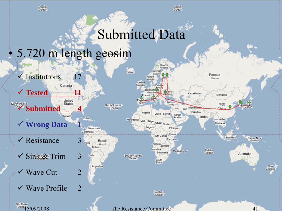
•
5.720 m length geosim
Institutions 17
Tested 11
Submitted 4
Wrong Data 1
Resistance 3
Sink & Trim 3
Wave Cut 2
Wave Profile 2
Submitted Data
15/09/2008 The Resistance Committee 41
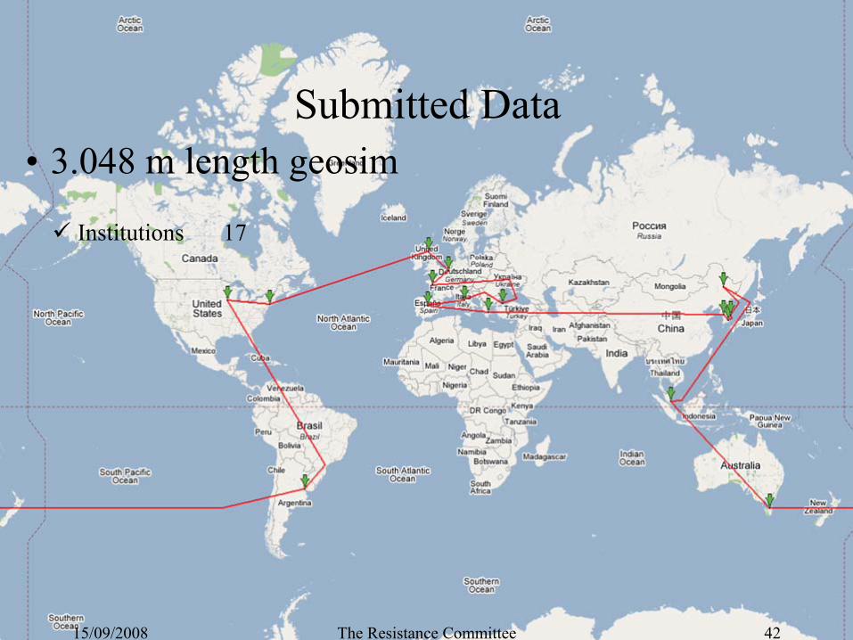
•
3.048 m length geosim
Institutions 17
Submitted Data
15/09/2008 The Resistance Committee 42
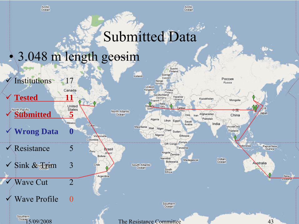
•
3.048 m length geosim
Institutions 17
Tested 11
Submitted 5
Wrong Data 0
Resistance 5
Sink & Trim 3
Wave Cut 2
Wave Profile 0
Submitted Data
15/09/2008 The Resistance Committee 43
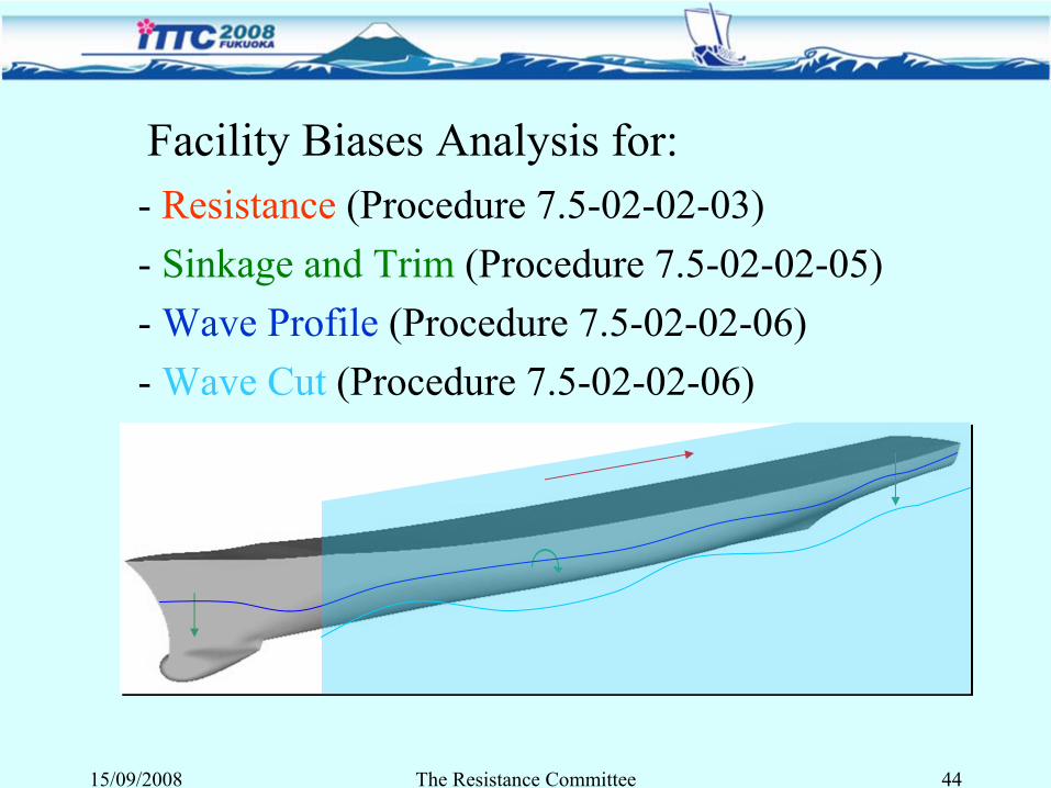
Facility Biases Analysis for:-
Resistance
(Procedure 7.5-02-02-03)
-
Sinkage and Trim
(Procedure 7.5-02-02-05)-
Wave Profile
(Procedure 7.5-02-02-06)
-
Wave Cut
(Procedure 7.5-02-02-06)
15/09/2008 The Resistance Committee 44
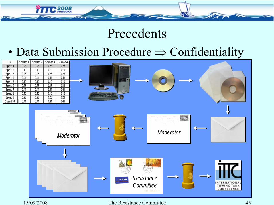
•
Data Submission Procedure ⇒ Confidentiality
ModeratorModerator
ResistanceCommittee
Precedents
15/09/2008 The Resistance Committee 45
Fr Session 1 Session 2 Session 3 Session 4 Speed 1 0,28 0,28 0,28 0,28 Speed 2 0,10 0,10 0,10 0,10 Speed 3 0,28 0,28 0,28 0,28 Speed 4 0,41 0,41 0,41 0,41 Speed 5 0,10 0,10 0,10 0,10 Speed 6 0,28 0,28 0,28 0,28 Speed 7 0,41 0,41 0,41 0,41 Speed 8 0,10 0,10 0,10 0,10 Speed 9 0,28 0,28 0,28 0,28 Speed 10 0,41 0,41 0,41 0,41
Fr Session 1 Session 2 Session 3 Session 4 Speed 1 0,28 0,28 0,28 0,28 Speed 2 0,10 0,10 0,10 0,10 Speed 3 0,28 0,28 0,28 0,28 Speed 4 0,41 0,41 0,41 0,41 Speed 5 0,10 0,10 0,10 0,10 Speed 6 0,28 0,28 0,28 0,28 Speed 7 0,41 0,41 0,41 0,41 Speed 8 0,10 0,10 0,10 0,10 Speed 9 0,28 0,28 0,28 0,28 Speed 10 0,41 0,41 0,41 0,41
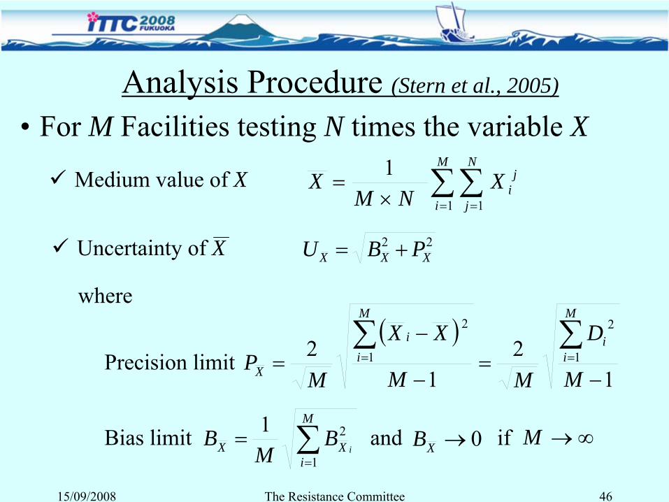
Analysis Procedure (Stern et al., 2005)
•
For M Facilities testing N times the variable X
∑∑= =×
=M
i
N
j
jiX
NMX
1 1
1
22XXX PBU +=
∑=
=M
iXX i
BM
B1
21
Medium value of X
Uncertainty of X
where
( )1
21
2 1
2
1
2
−=
−
−=
∑∑==
M
D
MM
XX
MP
M
ii
M
ii
XPrecision limit
Bias limit and if0→XB ∞→M
15/09/2008 The Resistance Committee 46
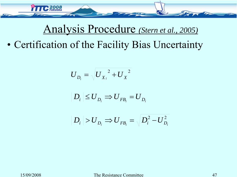
•
Certification of the Facility Bias Uncertainty
22XXD UUU
ii+=
iii DFBDi UUUD =⇒≤
22iii DiFBDi UDUUD −=⇒>
15/09/2008 The Resistance Committee 47
Analysis Procedure (Stern et al., 2005)
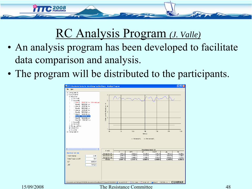
RC Analysis Program (J. Valle)•
An analysis program has been developed to facilitate data comparison and analysis.
•
The program will be distributed to the participants.
15/09/2008 The Resistance Committee 48
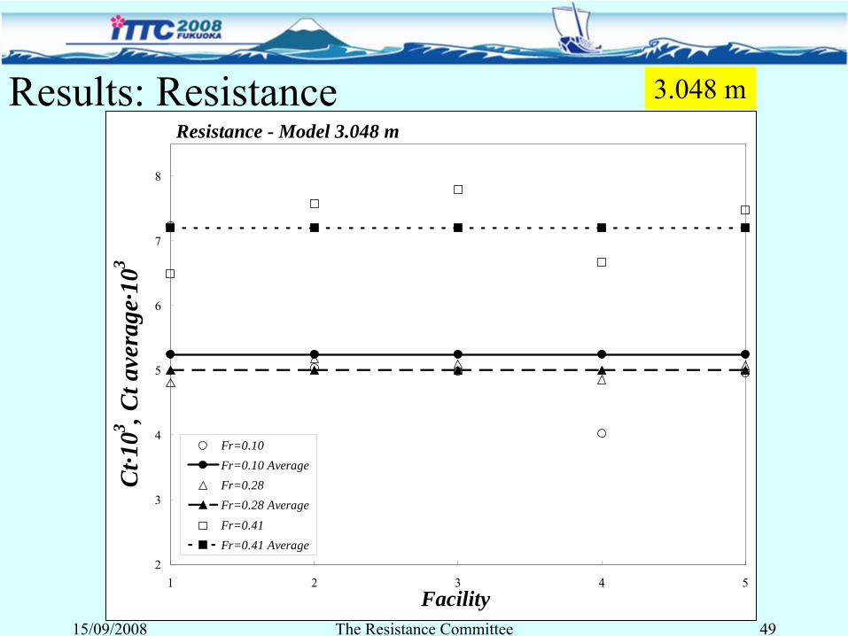
Results: ResistanceResistance - Model 3.048 m
2
3
4
5
6
7
8
1 2 3 4 5Facility
Fr=0.10Fr=0.10 AverageFr=0.28Fr=0.28 AverageFr=0.41Fr=0.41 Average
Ct·1
03 , Ct a
vera
ge·1
03
15/09/2008 The Resistance Committee 49
3.048 m
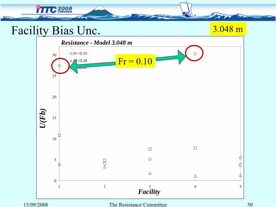
Resistance - Model 3.048 m
0
5
10
15
20
25
30
1 2 3 4 5Facility
Fr=0.10
Fr=0.28
Fr=0.41
U(F
b)
15/09/2008 The Resistance Committee 50
Facility Bias Unc. 3.048 m
Fr = 0.10
Conclusions•
The data is still very short to analyze uncertainties.
•
ITTC recommended procedures 7.5-02-02-03, 7.5-02-02-05 and 7.5-02-02-06 and referenced worksheets have been used.
•
Some resistance files present significant oscillations.
•
Facility bias uncertainties are normally larger for the smaller Froude numbers.
•
Sinkage and trim results are not available for all the facilities. Uncertainties obtained for the trim are very large in some cases.
15/09/2008 The Resistance Committee 51
•
Only two facilities have sent wave profile data and in both cases data was incomplete.
•
Only four facilities, two for each model, have sent wave elevation data.
•
Wave elevation and wave profile analysis have presented some special problems due to the phase of the waves.
•
Please, send the data ASAP and submit the data in the required format
Conclusions
15/09/2008 The Resistance Committee 52
8. Design and Optimization
15/09/2008 The Resistance Committee 53
Methods and problems ─ Variable Fidelity and Metamodels
─ Grid Regeneration and Deformation
─ Derivative Based and Derivative Free Methods
─ Uncertainty in Design OptimizationApplications
15/09/2008 The Resistance Committee 54
Developments in CFD and computer power lead to some progress in Simulation Based Design (SBD)
Variable Fidelity and Metamodels• Maximize the use of low fidelity, cheaper models in iterative procedures with occasional, but systematic (trust region), recourse to higher fidelity• Use of surrogated model to reduce the computational cost
Grid Regeneration and Deformation • Robustness still an issue
Derivative Based and Derivative Free Methods• Adjoint methods: efficient but only for single objective and for
local
optimization problems• Derivative free: more expensive but suited for multiobjective and global optimization
15/09/2008 The Resistance Committee 55
Doctors and Scrace (2003) optimized the configuration of a trimaran using a potential flow model.
Tahara et al. (2007) Optimized a high speed catamaran comparing PF- based and RANS-based SBD with global optimization algorithms
Zalek et al. (2006), Resistance and seakeeping optimization
Parsons et al. (2004) different multicriteria formulations to be
computed with a conventional scalar method.
ConclusionsLack of confidence in CFD reflects in sporadic use of SBD from shipyards
Navies and sailboat design seems to lead the use of SBD
Applications
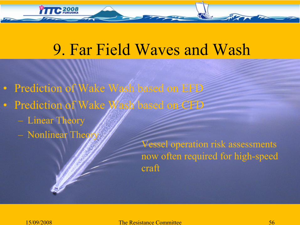
9. Far Field Waves and Wash
•
Prediction of Wake Wash based on EFD•
Prediction of Wake Wash based on CFD–
Linear Theory
–
Nonlinear Theory
15/09/2008 The Resistance Committee 56
Vessel operation risk assessments now often required for high-speed craft
Far Field Waves and Wash EFD Prediction
•
Limitations in facility width has likely contributed to increase in site-specific full scale experiments•
Recent examples include: Parnell et al. (2007), Soomere (2005), Velegrakis et al. (2006), Kumar et al. (2007), Varyani (2006), Balzerek and Koslowski (2007), Macfarlane and Cox (2004)
•
Use of large scale manned models•
(Chalkias and Grigoropoulos, 2007)
•
Correlation between model and full scale experiments•
(MacFarlane 2006,2008)
15/09/2008 The Resistance Committee 57
Far Field Waves and Wash CFD Prediction -
Linear Theory
•
Potential flow panel methods•
(Chalkias and Grigoropoulos, 2005)
•
Michell’s thin ship wave resistance theory•
(Lazauskas, 2007)
•
Soomere et al (2005) suggest that linear wave theory is not applicable for long period waves generated by high-speed craft operating in shallow water
15/09/2008 The Resistance Committee 58
Far Field Waves and Wash CFD Prediction -
Nonlinear Theory
•
The Korteweg-de Vries (KdV) equation is proposed for modelling long waves in shallow water (Soomere et al 2005)
•
Sakamoto et al (2007) suggest use of URANS method•
Soomere (2007) review many various methods to predict the generation of solitons
•
Soding (2006) suggests use of nonlinear Rankine source methods for near-field waves, combined with constant-depth method for far field waves
15/09/2008 The Resistance Committee 59
Far Field Waves and Wash CFD Prediction -
Nonlinear Theory (cont.)
•
Prediction of ship wash near the shore•
Hong and Doi (2006), Erikson et al (2005)
•
Prediction of ship wash during the passage through trans-critical speed regime (unsteady effects)•
Torsvik et al. (2006) and Torsvik (2006)
15/09/2008 The Resistance Committee 60
Far Field Waves and Wash Conclusions
•
Conclusions drawn by 24th
ITTC RC largely still hold
•
It is necessary to validate numerical models•
There remains a lack of appropriate benchmark data publicly available
•
Insufficient experience presently exists to propose general guidelines for prediction of far field waves and wash effects
15/09/2008 The Resistance Committee 61
15/09/2008 The Resistance Committee 62
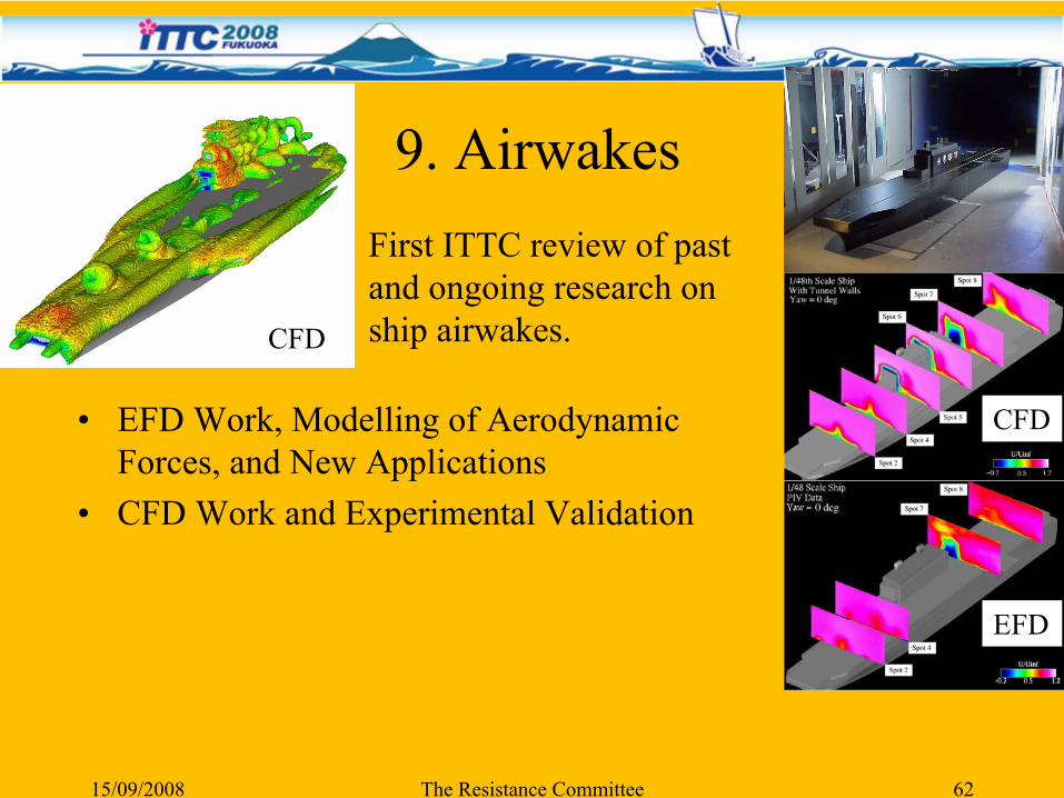
9. Airwakes
•
EFD Work, Modelling of Aerodynamic Forces, and New Applications
•
CFD Work and Experimental Validation
CFD
CFD
EFD
First ITTC review of past and ongoing research on ship airwakes.
EFD Work, Modeling of Aerodynamic Forces, and New Applications
•
Early Work:–
The first comprehensive and very systematic EFD work was reported by Hughes (1930).
•
In the 1950s:–
Investigation on effect of wind on the maneuverability of train ferries, and relatively small ships, e.g., fishing boats and small cargo ships.
•
In the 1960s through 1970s:–
Effort was directed toward very detailed wind tunnel measurements for other commercial ships and naval ships.
–
Many studies on modeling of aerodynamic forces and moments to develop empirical formula were initiated.
15/09/2008 The Resistance Committee 63
•
In the 1980s and 1990s:–
As ship design was modernized, continuous efforts on developing EFD databases and modeling of aerodynamic forces and moments were made. For example, VLCC, PCC, and LNG became new applications.
•
More recent work:–
EFD techniques were more advanced, and more realistic and complex wind and ship conditions were considered.
•
New Applications (In the 2000s):–
Prediction and control of ship airwakes and the interactions with aircraft (airplanes or helicopters).
15/09/2008 The Resistance Committee 64
EFD Work, Modeling of Aerodynamic Forces, and New Applications
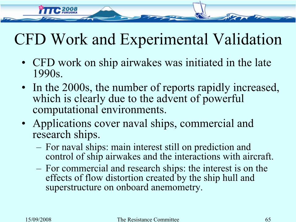
CFD Work and Experimental Validation•
CFD work on ship airwakes was initiated in the late 1990s.
•
In the 2000s, the number of reports rapidly increased, which is clearly due to the advent of powerful computational environments.
•
Applications cover naval ships, commercial and research ships.–
For naval ships: main interest still on prediction and control of ship airwakes and the interactions with aircraft.
–
For commercial and research ships: the interest is on the effects of flow distortion created by the ship hull and superstructure on onboard anemometry.
15/09/2008 The Resistance Committee 65
The Resistance Committee
Final Report
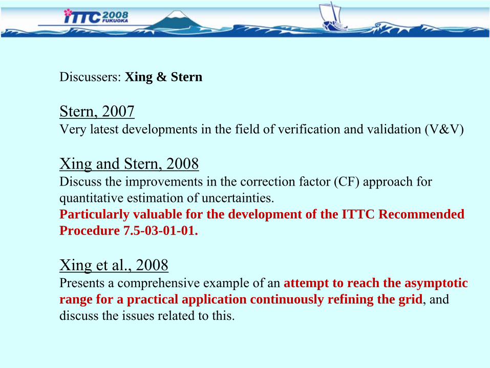
Discussers:
Xing & Stern
Stern, 2007Very latest developments in the field of verification and validation (V&V)
Xing and Stern, 2008 Discuss the improvements in the correction factor (CF) approach for quantitative estimation of uncertainties. Particularly valuable for the development of the ITTC Recommended Procedure 7.5-03-01-01.
Xing et al., 2008Presents a comprehensive example of an attempt to reach the asymptotic range for a practical application continuously refining the grid, and discuss the issues related to this.