電子回路論第12回
Electric Circuits for Physicists
東京大学理学部・理学系研究科
物性研究所
勝本信吾
Shingo Katsumoto


Outline 6.4 Discrete signal
6.4.1 Sampling theorem
6.4.2 Pulse amplitude modulation (PAM)
6.4.3 Discrete Fourier transform
6.4.4 z-transform
6.4.5 Transfer function of discrete time signal
Ch.7 Digital signals and circuits
7.2 Logic gates
7.3 Implementation of logic gates
7.4 Circuit implementation and simplification of
logic operation

6.4 Discrete signal
6.4.1 Sampling theorem
Sampled signal
Isao Someya
1915-2007
Claude Shannon
1916-2001
t
x(t)
w
X(w)
d-functions with the period t
t
x(t) t
1928 H. Nyquist
1949 C. Shannon
染谷勲

6.4.1 Sampling theorem

6.4.1 Sampling theorem
“Cutting out” the frequency spectrum
2p/t 𝜔ℎ: Highest frequency
in 𝑋 𝜏(𝜔)

6.4.1 Sampling theorem: Reconstructing signal
𝑃𝜋𝜏(𝜔)
w
−𝜋
𝜏
𝜋
𝜏
1
xsi
nc(
x)-10 0 10
0
0.5
1

6.4.2 Pulse amplitude modulation (PAM)
t t
s(t)
t f(t)
Carrier: 𝛿𝜏(𝑡)
Demodulation = Reconstruction of continuous signal
from sampled data.

Demodulation of PAM and a trick in the sampling theorem
In the sampling theorem, though we only have discrete-time data, we can reconstruct complete original signal.
↑
Assumption: we have data in infinite period [−∞, +∞].
However in actual situations we can never have such data.
Need to consider handling data in a finite period.
6.4.3 Discrete Fourier transform
t 0
f (t)
z
t
-z 0 z 2z
𝑓 (𝑡)
Fourier expansion:
Assumption:
can be assumed without
loosing generality

6.4.3 Discrete Fourier transform
Twiddle factor:
Discreteness:

6.4.3 Discrete Fourier transform
Twiddle factor:
Discrete Fourier transform:
(DFT)

6.4.3 Discrete Fourier transform

6.4.4 z-transform
Discrete Laplace transform: z-transform
one-sided z-transform

6.4.4 z-transform

6.4.4 z-transform

6.4.5 Transfer function for discrete time signal
ℎ𝑛: (impulse) response to 𝛿(𝑛𝜏), response to discrete signal 𝑓𝑛 = 𝑓 (𝑛𝜏)
: Transfer function

Crystal lattice and X-ray diffraction
Max von Laue
1879-1960
Diamond lattice
Laue pattern
[100]
[111]
[100] [010]

Optical Frequency Comb

Frequency Comb
Theodor Hänsch, Max-Planck Institute, Science 2008

Measurement of the Doppler effect in cosmic expansion

Byzantine mosaic
Chartres Blue
(Stained glass)
Chapter 7
Digital signal
and circuits

Ch.7 Digital signal and circuits
t
s (t)
t 2t 5t
Discrete time analog
t
d (t)
Value discretized → Digital signal
Signal unit : 0 xor 1 (bit)
Boolean algebra : F xor T
Voltage level : L xor H
Multiple bit → binary operation → parallel signal

7.2 Logic gates
Digital signal=logic value Logic operation : logic gates
Combinational logic Truth table
Sequential logic Timing chart
De Morgan's laws: 𝑥 + 𝑦 = 𝑥 ∙ 𝑦 , 𝑥 ∙ 𝑦 = 𝑥 + 𝑦

7.2.1 Combinational logic: Single input gates
Truth table Circuit symbol
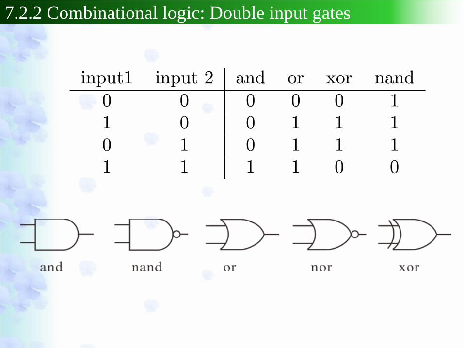
7.2.2 Combinational logic: Double input gates

7.2.3 Sequential logic: Flip-Flop (FF)
RS (reset-set) Flip-Flop (FF)
Symbol
Truth table
Equivalent circuit with discrete gates

7.2.3 Sequential logic: Flip-Flop (FF)
JK Flip-Flop
Symbol
Truth table
Equivalent circuit with discrete gates

7.2.3 Sequential logic: D-FF, T-FF
D-FF
T-FF
Symbol
Symbol
Truth table
Truth table

7.2.4 Sequential logic: Counters
Unsynchronized
counter
(ripple counter)
Timing
chart

7.2.4 Sequential logic: Counters
Synchronized counter
Equivalent
circuit with
discrete gates
Timing chart

7.3 Implementation of logic gates
TTL (transistor-transistor logic) CMOS (complimentary MOS)
NAND gates

7.3 Implementation of logic gates
LT Spice
simulation

7.3 Implementation of logic gates
Voltage levels diagram

TTL logic family evolution
Legacy: don’t use
in new designs
Widely used today

CMOS logic family evolution
obsolete
• Reduction of dynamic losses through
successively decreasing supply voltages:
12V 5V 3.3V 2.5V 1.8V
CD4000 LVC/ALVC/AVC
• Power reduction is one of the keys to
progressive growth of integration
General trend:

Summary
TTL
Logic
Family
CMOS
TPD Trise/fall VIH,min VIL,max VOH,min VOL,max Noise
Margin

Exercise F-1
Show that the following circuit works as a demodulator of
frequency modulation (FM) signal (quadrature demodulator).
Phase shifter
multiplier input output Low-pass
filter
Here the phase shifter gives the shift
proportional to the frequency difference
between input and the career frequency
𝜔0. The shift at 𝜔0 is 𝜋/2 as shown in
the right (this can be achieved with
resonant circuits). The low-pass filter
cuts components with frequencies as
high as 𝜔0.
∆𝜃
𝜋
2
𝜔 𝜔0
∆𝜃 = 𝑎 𝜔0 − 𝜔 +𝜋
2

Exercise F-1
(hint) Assume the original signal 𝑓(𝑡) is much slower than
the carrier 𝐴 cos 𝜔0𝑡 . Then the input can be
approximated as
Then the phase shifter output is
Taking product and high-frequency filtering gives …
(use 𝑎𝑘𝑓𝑓(𝑡) ≪ 1).

Exercise F-2
In the following phase lock loop (PLL) circuit, the initial (𝑡 = 0)
oscillation frequency of voltage-controlled oscillator (VCO) 𝜔
deviates from 𝑁𝜔0 by ∆𝜔. Obtain the relaxation time of 𝜔 to 𝑁𝜔0.
𝑁- divider
Phase
comparator
Loop
filter VCO
Output
freq. 𝜔
Input
freq. 𝜔0
freq. 𝜔/𝑁
𝑉𝑐(𝜃𝑖 − 𝜃𝑜/𝑁) gain 𝐺𝑝
phase 𝜃𝑜 phase 𝜃𝑖
(hint) Here we can put 𝜃𝑖 = 0 hence input = 𝑉𝑖 sin𝜔0𝑡 without
loosing generality. Similarly output = 𝑉𝑜 sin 𝑁𝜔0𝑡 + 𝜃𝑜(𝑡) .
Now 𝜔 = 𝑁𝜔0 + 𝑑𝜃𝑜/𝑑𝑡 and it is easy to write 𝑑𝜃𝑜/𝑑𝑡 with 𝐴,
𝐺𝑝, 𝑉𝑐, 𝜃𝑜(𝑡) and a constant.
Coef. 𝐴 for freq. shift

Exercise F-3
Solve the difference equation below with z-transform.
(hint) z-transform of 𝑛 is as in the table (slide no.14).
Then z-transform of 𝑥(𝑛) : 𝑋(𝑧) is easily obtained. Inverse z-
transform gives 𝑥 𝑛 .
Answer sheet submission deadline: 11th Jan. 2017.
Recommended