Embed Size (px)
Citation preview
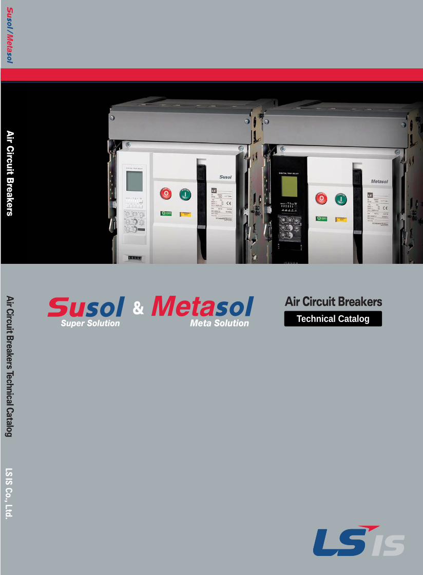
Air C
ircuit Breakers
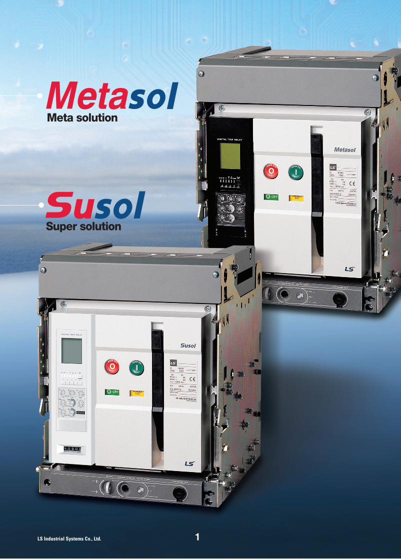
Technical CatalogSuper Solution Meta Solution
Air
Circu
itB
reake
rsTe
chnicalC
atalo
g
Tư vấn chọn sản phẩm
Giao hàng tận nơi
Hỗ trợ kỹ thuật
Chính sách hậu mãi đa dạng
DỊCH VỤ CHĂM SÓC KHÁCH HÀNG TOÀN DIỆN
Nhà cung cấp thiết bị điện chuyên nghiệpEmail: [email protected]: 0909 41 61 43
CÔNG TY TNHH THƯƠNG MẠI KỸ THUẬT ASTERSố 7/31 KDC Thương Mại Sóng Thần, Kp. Nhị Đồng 1, P. Dĩ An, Tx. Dĩ An, Bình Dương
Tel: (0650) 3617 012Fax: (0650) 3617 011
11
Super solution
Meta solution
Technical catalog for Susol & Metasol ACB
This technical document can be revised or withdrawn at any timewithout prior notice. No part of this publication shall be reproducedor utilized in any form or by any means. The persons who are in breach of terms and conditions will be subjected to compensatefor any loss lf our company.All patent rights are reserved.
Title : Technical catalogue of Susol&metasol ACB
Document No : Tech, ACB 695-001
Issued team : Electric equip.)Technology management team
Issued date : June, 2007
154 Technical materials for Susol & Metasol ACB
2 Technical catalog for Susol & Metasol ACB
3
18
22
27
58
68
76
81
91
128
135
150
A Overview
B Structure and Operation
C Internal Electrical Accessory
D Digital Trip Relay
E Digital Trip Relay Accessory
F Installation and Service Condition
G Operation
H Protective Coordination
I Accessories
J Handling and Maintenance
K Control Circuit and Dimension
L Ordering Sheet
Contents
A.Overview
4
6
8
9
17
1. Product Introduction
2. Accessories
3. Introduction of Digital Trip Relay
4. Ratings
5. Externals and Inscriptions
3
4 Technical catalog for Susol & Metasol ACB
Technical catalog for Susol & Metasol ACB
A
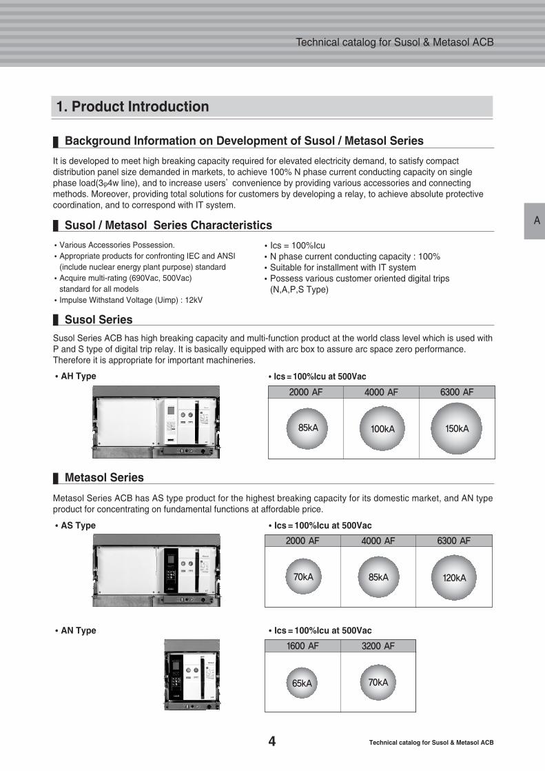
Background Information on Development of Susol / Metasol Series
It is developed to meet high breaking capacity required for elevated electricity demand, to satisfy compactdistribution panel size demanded in markets, to achieve 100% N phase current conducting capacity on singlephase load(3φ4w line), and to increase users’convenience by providing various accessories and connectingmethods. Moreover, providing total solutions for customers by developing a relay, to achieve absolute protectivecoordination, and to correspond with IT system.
Susol / Metasol Series Characteristics
�Ics = 100%Icu�N phase current conducting capacity : 100%�Suitable for installment with IT system�Possess various customer oriented digital trips
(N,A,P,S Type)
�Various Accessories Possession.�Appropriate products for confronting IEC and ANSI
(include nuclear energy plant purpose) standard�Acquire multi-rating (690Vac, 500Vac)
standard for all models�Impulse Withstand Voltage (Uimp) : 12kV
1. Product Introduction
Susol SeriesSusol Series ACB has high breaking capacity and multi-function product at the world class level which is used withP and S type of digital trip relay. It is basically equipped with arc box to assure arc space zero performance.Therefore it is appropriate for important machineries.
��AH Type
Metasol Series
Metasol Series ACB has AS type product for the highest breaking capacity for its domestic market, and AN typeproduct for concentrating on fundamental functions at affordable price.
��AS Type ��Ics = 100%Icu at 500Vac
��AN Type ��Ics = 100%Icu at 500Vac
2000 AF 4000 AF 6300 AF
150kA100kA85kA
��Ics = 100%Icu at 500Vac
2000 AF 4000 AF 6300 AF
120kA85kA70kA
1600 AF 3200 AF
70kA65kA
5
Overview
A
The CE Marking indicates that a product complies with the requirements of the applicable European Directives.These Directives for products set out essential requirements which must be met before products may be marketedor traded within the European Economic Area. Thus, a displayed CE Marking indicates that a product complies withthe applicable Directives.
CE Conformance Marking
�Certificate of conformance test (KEMA - IEC 60947)�Test report (KEMA / KERI)
Susol / Metasol ACB have obtained following certificates and They are available upon a request
1. Product Introduction
��IEC 60947-1Low-voltage switchgear and controlgear - Part 1: General rules
��IEC 60947-2Low-voltage switchgear and controlgear - Part 2: Circuit-breakers
Standard and Approvals
It has obtained approvals in accordance with following international standard and can be applicable to servicecondition defined from international standard.
6 Technical catalog for Susol & Metasol ACB
Technical catalog for Susol & Metasol ACB
A
2. Accessories
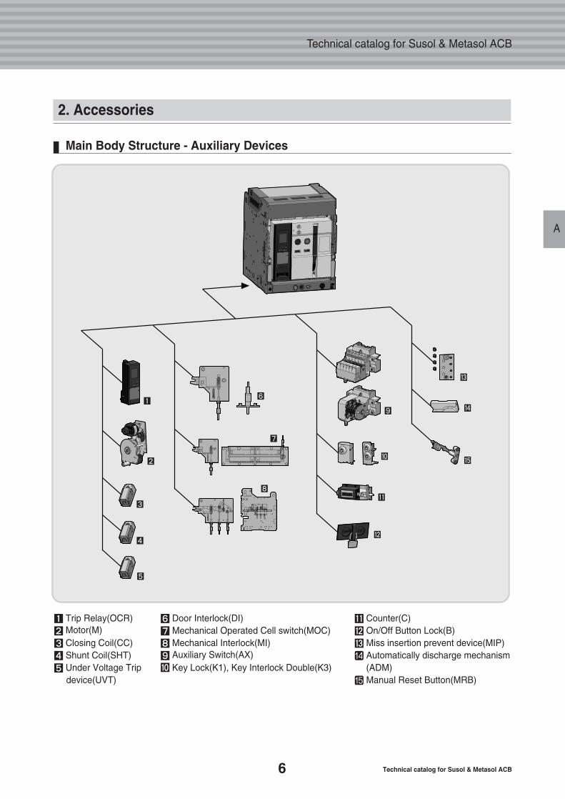
Main Body Structure - Auxiliary Devices
� Door Interlock(DI)� Mechanical Operated Cell switch(MOC)� Mechanical Interlock(MI)� Auxiliary Switch(AX)� Key Lock(K1), Key Interlock Double(K3)
� Counter(C)� On/Off Button Lock(B)� Miss insertion prevent device(MIP)� Automatically discharge mechanism
(ADM)� Manual Reset Button(MRB)
� Trip Relay(OCR)� Motor(M)� Closing Coil(CC)� Shunt Coil(SHT)� Under Voltage Trip
device(UVT)
�
�
�
�
�
�
��
�
�
�
�
�
�
�
7
A
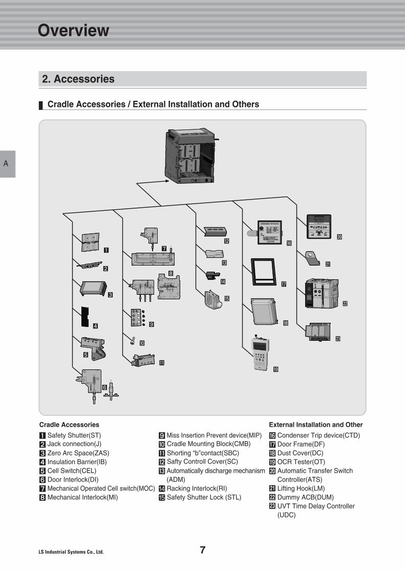
Cradle Accessories / External Installation and Others
� Safety Shutter(ST)� Jack connection(J)� Zero Arc Space(ZAS)� Insulation Barrier(IB)� Cell Switch(CEL)� Door Interlock(DI)� Mechanical Operated Cell switch(MOC)� Mechanical Interlock(MI)
� Miss Insertion Prevent device(MIP)� Cradle Mounting Block(CMB)� Shorting “b”contact(SBC)� Safty Controll Cover(SC)� Automatically discharge mechanism
(ADM)� Racking Interlock(RI)� Safety Shutter Lock (STL)
Cradle Accessories External Installation and Other
� Condenser Trip device(CTD)� Door Frame(DF)� Dust Cover(DC)� OCR Tester(OT)� Automatic Transfer Switch
Controller(ATS)Lifting Hook(LM)Dummy ACB(DUM)UVT Time Delay Controller(UDC)
Overview
2. Accessories
212223
�
�
�
�
�
�
�
�
�
�
�
�
�
�
�
�
�
�
�
�
8 Technical catalog for Susol & Metasol ACB
Technical catalog for Susol & Metasol ACB
A
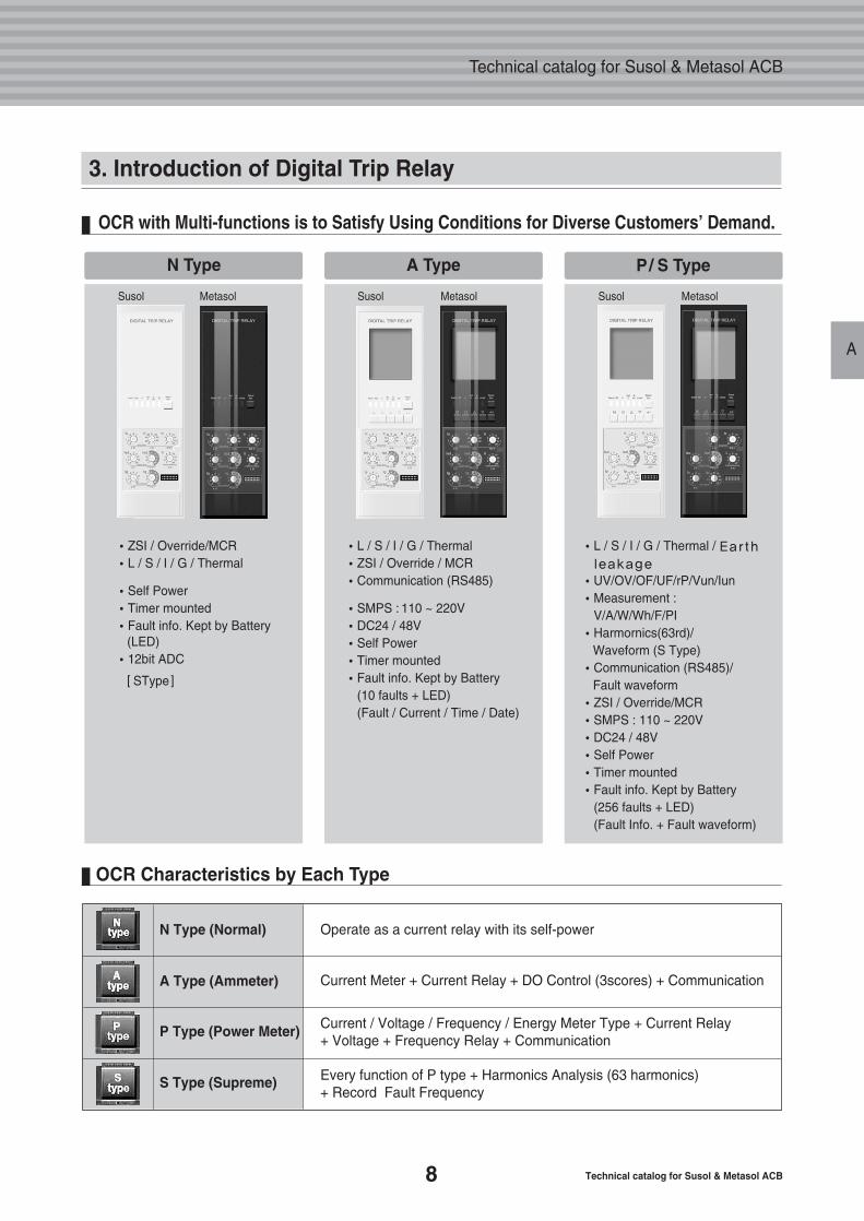
OCR with Multi-functions is to Satisfy Using Conditions for Diverse Customers’ Demand.
N Type A Type P/ S Type
N Type (Normal)
A Type (Ammeter)
P Type (Power Meter)
S Type (Supreme)
Operate as a current relay with its self-power
Current Meter + Current Relay + DO Control (3scores) + Communication
Current / Voltage / Frequency / Energy Meter Type + Current Relay + Voltage + Frequency Relay + Communication
Every function of P type + Harmonics Analysis (63 harmonics) + Record Fault Frequency
�L / S / I / G / Thermal / Earth
leakage
�UV/OV/OF/UF/rP/Vun/Iun�Measurement :
V/A/W/Wh/F/PI�Harmornics(63rd)/
Waveform (S Type)�Communication (RS485)/
Fault waveform�ZSI / Override/MCR�SMPS : 110 ~ 220V�DC24 / 48V�Self Power�Timer mounted�Fault info. Kept by Battery
(256 faults + LED)(Fault Info. + Fault waveform)
�L / S / I / G / Thermal�ZSI / Override / MCR�Communication (RS485)
�SMPS : 110 ~ 220V�DC24 / 48V�Self Power�Timer mounted�Fault info. Kept by Battery
(10 faults + LED)(Fault / Current / Time / Date)
�ZSI / Override/MCR�L / S / I / G / Thermal
�Self Power�Timer mounted�Fault info. Kept by Battery
(LED)�12bit ADC
� SType�
3. Introduction of Digital Trip Relay
OCR Characteristics by Each Type
Susol Metasol Susol Metasol Susol Metasol
9
Overview
A
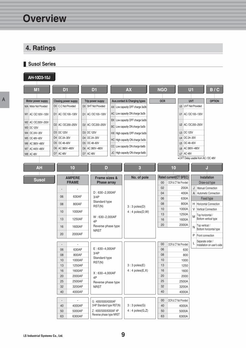
Susol Series
4. Ratings
AH-10D3-10J
SusolRated current(CT SFEC)
OCR & CT Not Provided
200A
400A
630A
800A
1000A
1250A
1600A
2000A
00
02
04
06
08
10
13
16
20
OCR & CT Not Provided
4000A
5000A
6300A
00
40
50
63
No. of pole
3 : 3 poles(D)
4 : 4 poles(D,W)
3 : 3 poles(G)
4 : 4 poles(G,Z)
D : 630~2,000AF3/4PStandard typeRST(N)
W : 630~2,000AF4PReverse phase typeNRST
G : 4000/5000/6300AF 3/4P Standard type RST(N)
Z : 4000/5000/6300AF 4P Reverse phase type NRST
AH 103D10
AMPEREFRAME
Frame sizes &Phase array
-
06
08
10
13
16
20
-
630AF
800AF
1000AF
1250AF
1600AF
2000AF
-
4000AF
5000AF
6300AF
-
40
50
63
3 : 3 poles(E)
4 : 4 poles(E,X)
-
06
08
10
13
16
20
25
32
40
-
630AF
800AF
1000AF
1250AF
1600AF
2000AF
2500AF
3200AF
4000AF
00
06
08
10
13
16
20
25
32
40
Installation
J
A
H
V
M
N
P
L
J
Draw-out type
Fixed typeHorizontal Connection
Vertical Connection
Top horizontal /Bottom vertical type
Top vertical /Bottom horizontal type
Front connection
Separate order /Installation on user’s side
Manual Connection
Autometic Connection
D1
Closing power suppy
D0
D1
D2
D3
D4
D5
D6
D7
C.C Not Provided
AC / DC100~130V
AC / DC200~250V
DC 125V
DC 24~30V
DC 48~60V
AC 380V~480V
AC 48V
D1
Trip power suppy
D0
D1
D2
D3
D4
D5
D6
D7
SHT Not Provided
AC / DC100~130V
AC / DC200~250V
DC 125V
DC 24~30V
DC 48~60V
AC 380V~480V
AC 48V
AX
Aux.contact & Charging types
AX
AC
BX
BC
HX
HC
CC
JC
Low capacity OFF charge 3a3b
Low capacity ON charge 3a3b
Low capacity OFF charge 5a5b
Low capacity ON charge 5a5b
High capacity OFF charge 5a5b
High capacity ON charge 5a5b
Low capacity ON charge 6a6b
High capacity ON charge 6a6b
NGO
OCR
U1
UVT
U0
U1
U2
U3
U4
U5
U6
U7
UVT Not Provided
AC / DC100~130V
AC / DC200~250V
DC 125V
DC 24~30V
DC 48~60V
AC 380V~480V
AC 48V
�UVT Delay usable from AC / DC 48V
B / C
OPTION
M1
Motor power suppy
MA
M1
M2
M3
M4
M5
M6
M7
M8
Motor Not Provided
AC / DC100V~130V
AC / DC200V~250V
DC 125V
DC 24V~30V
DC 48V~60V
AC 380V~480V
AC 440V~480V
AC 48V
E : 630~4,000AF3/4PStandard typeRST(N)
X : 630~4,000AF4PReverse phase typeNRST
OCR & CT Not Provided
630
800
1000
1250
1600
2000
2500A
3200A
4000A
10 Technical catalog for Susol & Metasol ACB
Technical catalog for Susol & Metasol ACB
A
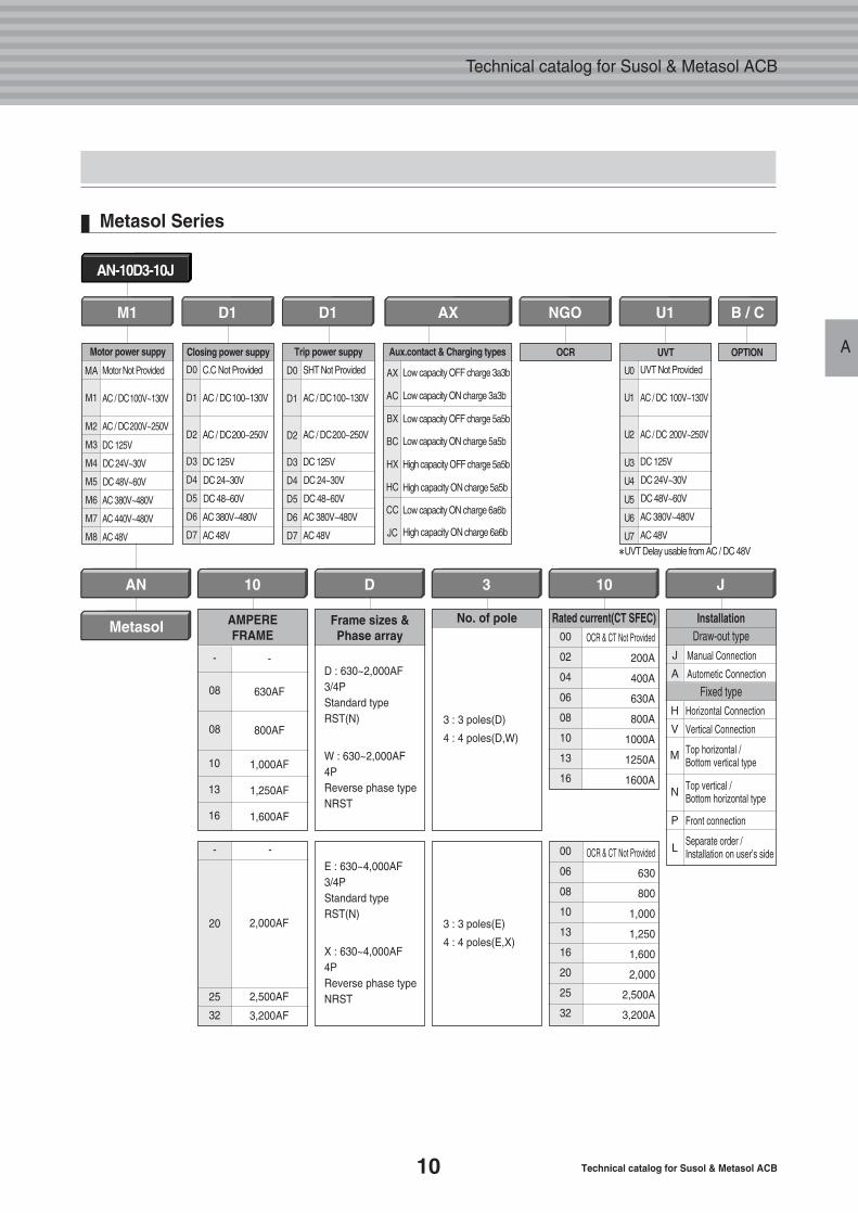
AN-10D3-10J
Metasol Series
D1
Closing power suppy
D0
D1
D2
D3
D4
D5
D6
D7
C.C Not Provided
AC / DC100~130V
AC / DC200~250V
DC 125V
DC 24~30V
DC 48~60V
AC 380V~480V
AC 48V
D1
Trip power suppy
D0
D1
D2
D3
D4
D5
D6
D7
SHT Not Provided
AC / DC100~130V
AC / DC200~250V
DC 125V
DC 24~30V
DC 48~60V
AC 380V~480V
AC 48V
AX
Aux.contact & Charging types
AX
AC
BX
BC
HX
HC
CC
JC
Low capacity OFF charge 3a3b
Low capacity ON charge 3a3b
Low capacity OFF charge 5a5b
Low capacity ON charge 5a5b
High capacity OFF charge 5a5b
High capacity ON charge 5a5b
Low capacity ON charge 6a6b
High capacity ON charge 6a6b
NGO
OCR
B / C
OPTION
M1
Motor power suppy
MA
M1
M2
M3
M4
M5
M6
M7
M8
Motor Not Provided
AC / DC100V~130V
AC / DC200V~250V
DC 125V
DC 24V~30V
DC 48V~60V
AC 380V~480V
AC 440V~480V
AC 48V
U1
UVT
U0
U1
U2
U3
U4
U5
U6
U7
UVT Not Provided
AC / DC 100V~130V
AC / DC 200V~250V
DC 125V
DC 24V~30V
DC 48V~60V
AC 380V~480V
AC 48V
�UVT Delay usable from AC / DC 48V
MetasolRated current(CT SFEC)
OCR & CT Not Provided
200A
400A
630A
800A
1000A
1250A
1600A
00
02
04
06
08
10
13
16
No. of pole
3 : 3 poles(D)
4 : 4 poles(D,W)
D : 630~2,000AF3/4PStandard typeRST(N)
W : 630~2,000AF4PReverse phase typeNRST
Frame sizes &Phase array
AN 103D10
10
13
16
-
08
08
2,000AF
2,500AF
3,200AF
3 : 3 poles(E)
4 : 4 poles(E,X)
-
20
25
32
- 00
06
08
10
13
16
20
25
32
OCR & CT Not Provided
630
800
1,000
1,250
1,600
2,000
2,500A
3,200A
-
630AF
800AF
1,000AF
1,250AF
1,600AF
Installation
J
A
H
V
M
N
P
L
J
Draw-out type
Fixed type
Manual Connection
Autometic Connection
AMPEREFRAME
E : 630~4,000AF3/4PStandard typeRST(N)
X : 630~4,000AF4PReverse phase typeNRST
Horizontal Connection
Vertical Connection
Top horizontal /Bottom vertical type
Top vertical /Bottom horizontal type
Front connection
Separate order /Installation on user’s side
11
Overview
A
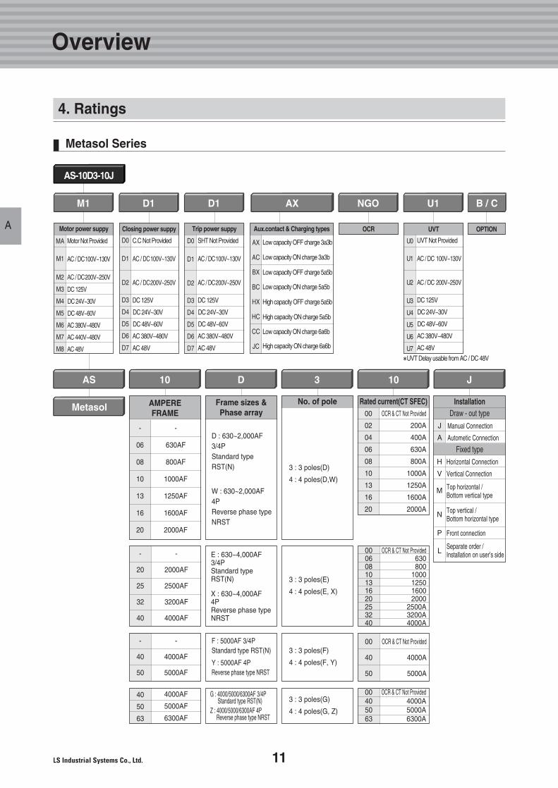
AS-10D3-10J
Metasol Series
M1
Motor power suppy
MA
M1
M2
M3
M4
M5
M6
M7
M8
Motor Not Provided
AC / DC100V~130V
AC / DC200V~250V
DC 125V
DC 24V~30V
DC 48V~60V
AC 380V~480V
AC 440V~480V
AC 48V
D1
Closing power suppy
D0
D1
D2
D3
D4
D5
D6
D7
C.C Not Provided
AC / DC100V~130V
AC / DC200V~250V
DC 125V
DC 24V~30V
DC 48V~60V
AC 380V~480V
AC 48V
D1
Trip power suppy
D0
D1
D2
D3
D4
D5
D6
D7
SHT Not Provided
AC / DC100V~130V
AC / DC200V~250V
DC 125V
DC 24V~30V
DC 48V~60V
AC 380V~480V
AC 48V
AX
Aux.contact & Charging types
AX
AC
BX
BC
HX
HC
CC
JC
Low capacity OFF charge 3a3b
Low capacity ON charge 3a3b
Low capacity OFF charge 5a5b
Low capacity ON charge 5a5b
High capacity OFF charge 5a5b
High capacity ON charge 5a5b
Low capacity ON charge 6a6b
High capacity ON charge 6a6b
NGO
OCR
U1
UVT
U0
U1
U2
U3
U4
U5
U6
U7
UVT Not Provided
AC / DC 100V~130V
AC / DC 200V~250V
DC 125V
DC 24V~30V
DC 48V~60V
AC 380V~480V
AC 48V
�UVT Delay usable from AC / DC 48V
B / C
OPTION
MetasolRated current(CT SFEC)
OCR & CT Not Provided
200A
400A
630A
800A
1000A
1250A
1600A
2000A
00
02
04
06
08
10
13
16
20
OCR & CT Not Provided4000A5000A6300A
00405063
No. of pole
3 : 3 poles(D)
4 : 4 poles(D,W)
3 : 3 poles(E)
4 : 4 poles(E, X)
3 : 3 poles(G)
4 : 4 poles(G, Z)
D : 630~2,000AF3/4PStandard typeRST(N)
W : 630~2,000AF4PReverse phase typeNRST
E : 630~4,000AF3/4PStandard type RST(N)
X : 630~4,000AF4PReverse phase type NRST
G : 4000/5000/6300AF 3/4P Standard type RST(N)
Z : 4000/5000/6300AF 4P Reverse phase type NRST
Frame sizes &Phase array
AS 103D10
AMPEREFRAME
-
06
08
10
13
16
20
-
630AF
800AF
1000AF
1250AF
1600AF
2000AF
4000AF
5000AF
6300AF
40
50
63
3 : 3 poles(F)
4 : 4 poles(F, Y)
-
20
25
32
40
-
2000AF
2500AF
3200AF
4000AF
-
4000AF
5000AF
-
40
50
OCR & CT Not Provided
4000A
5000A
00
40
50
00060810131620253240
Installation
J
A
H
V
M
N
P
L
J
Draw - out type
Fixed typeHorizontal Connection
Vertical Connection
Top horizontal /Bottom vertical type
Top vertical /Bottom horizontal type
Front connection
Separate order /Installation on user’s side
Manual Connection
Autometic Connection
4. Ratings
F : 5000AF 3/4P Standard type RST(N)
Y : 5000AF 4P Reverse phase type NRST
OCR & CT Not Provided630800
1000125016002000
2500A3200A4000A
12 Technical catalog for Susol & Metasol ACB
Technical catalog for Susol & Metasol ACB
A
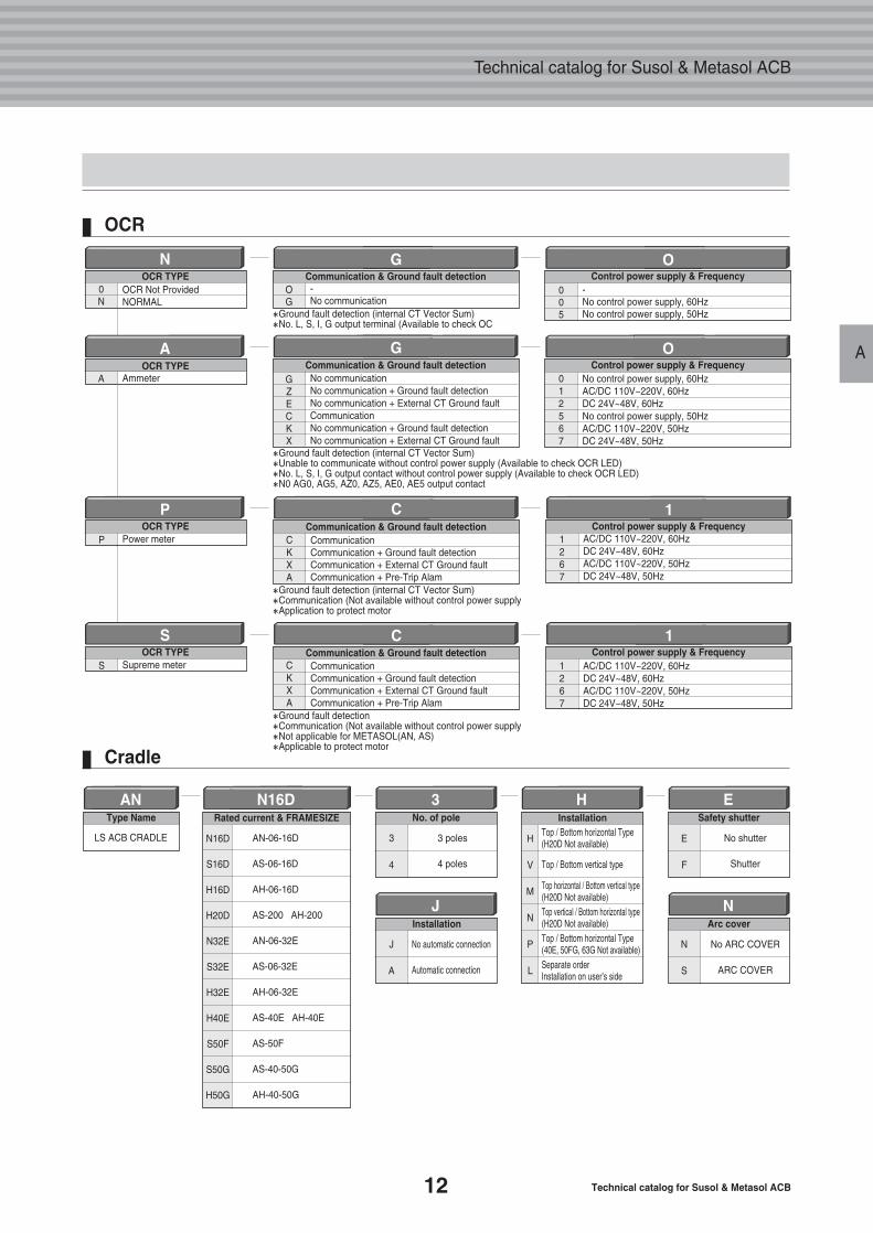
AN N16D H
OCR TYPE0N
OCR Not ProvidedNORMAL
N
Type Name
LS ACB CRADLE
Rated current & FRAMESIZE
3No. of pole
3
4
3 poles
4 poles
AN-06-16D
AS-06-16D
AH-06-16D
AS-200 AH-200
AN-06-32E
AS-06-32E
AH-06-32E
AS-40E AH-40E
AS-50F
AS-40-50G
AH-40-50G
ESafety shutter
E
F
No shutter
Shutter
JInstallation
J
A
No automatic connection
Automatic connection
NArc cover
N
S
No ARC COVER
ARC COVER
Installation
Control power supply & Frequency005
-No control power supply, 60HzNo control power supply, 50Hz
O
H
V
M
N
P
L
N16D
S16D
H16D
H20D
N32E
S32E
H32E
H40E
S50F
S50G
H50G
Top / Bottom horizontal Type(H20D Not available)
Top / Bottom vertical type
Top horizontal / Bottom vertical type(H20D Not available)Top vertical / Bottom horizontal type(H20D Not available)Top / Bottom horizontal Type(40E, 50FG, 63G Not available)Separate orderInstallation on user’s side
G
OG
-No communication
�Ground fault detection (internal CT Vector Sum)�No. L, S, I, G output terminal (Available to check OC
�Ground fault detection (internal CT Vector Sum)�Unable to communicate without control power supply (Available to check OCR LED)�No. L, S, I, G output contact without control power supply (Available to check OCR LED)�N0 AG0, AG5, AZ0, AZ5, AE0, AE5 output contact
AOCR TYPE
A Ammeter
OControl power supply & Frequency
012567
No control power supply, 60HzAC/DC 110V~220V, 60HzDC 24V~48V, 60HzNo control power supply, 50HzAC/DC 110V~220V, 50HzDC 24V~48V, 50Hz
GCommunication & Ground fault detection
GZECKX
No communicationNo communication + Ground fault detectionNo communication + External CT Ground faultCommunicationNo communication + Ground fault detectionNo communication + External CT Ground fault
�Ground fault detection (internal CT Vector Sum)�Communication (Not available without control power supply�Application to protect motor
�Ground fault detection�Communication (Not available without control power supply�Not applicable for METASOL(AN, AS)�Applicable to protect motor
POCR TYPE
P Power meter
SOCR TYPE
S Supreme meter
1Control power supply & Frequency
1267
AC/DC 110V~220V, 60HzDC 24V~48V, 60HzAC/DC 110V~220V, 50HzDC 24V~48V, 50Hz
1Control power supply & Frequency
1267
AC/DC 110V~220V, 60HzDC 24V~48V, 60HzAC/DC 110V~220V, 50HzDC 24V~48V, 50Hz
CCommunication & Ground fault detection
CKXA
CommunicationCommunication + Ground fault detectionCommunication + External CT Ground faultCommunication + Pre-Trip Alam
CCommunication & Ground fault detection
CKXA
CommunicationCommunication + Ground fault detectionCommunication + External CT Ground faultCommunication + Pre-Trip Alam
Communication & Ground fault detection
OCR
Cradle
13
Overview
A
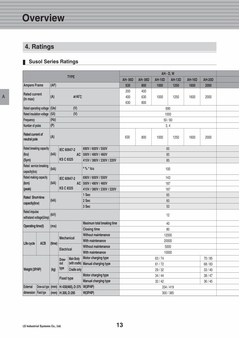
TYPEAH - D, W
Ampere Frame
Rated current(In max)
Rated current ofneutral pole
690V / 600V / 550V500V / 480V / 460V415V / 380V / 230V / 220V
690V / 600V / 550V500V / 480V / 460V415V / 380V / 230V / 220V1 Sec2 Sec3 Sec
Maximum total breaking time
Closing time
Motor charging typeManual charging type
Motor charging typeManual charging typeW(3P/4P)
W(3P/4P)
Without maintenanceWith maintenanceWithout maintenanceWith maintenance
Rated making capacity(Icm)(peak)
III % * Icu
Rated Short-time capacity(Icw)
Rated impulse withstand voltage(Uimp)
Operating time(t)
Life cycle
Weight (3P/4P)
Externaldimension
Draw-out typeFixed type
ACBMechanical
Electrical
Draw-outtype
Fixed type
Cradle only
Main Body(with cradle)
(AF)
(A) at40℃℃
(A)
(kA)IEC 60947-2
ACKS C 8325
IEC 60947-2AC
KS C 8325
(kA)
(kA)
(kA)
(kV)
(ms)
(mm)
(mm)H:430(460), D:375
H:300, D:295
(time)
(kg)
(Ue) (V)(Ui) (V)(Hz)(P)
6901000
50 / 603, 4
65
85
85
100
143
187
18765
6050
12
40
80
1200020000
5000
10000
334 / 419
300 / 385
63 / 74 70 / 8561 / 72 68 / 8329 / 32 33 / 4034 / 44 38 / 4732 / 42 36 / 45
Rated operating voltageRated insulation voltageFrequencyNumber of poles
AH- 06D AH- 08D AH-10D AH-13D AH-16D AH-20D630 800 1000 1250 1600 2000200 400400 630 1000 1250 1600 2000630 800
800 1000 1250 1600 2000630
Rated breaking capacity(Icu)(Sym)Rated service breaking capacity(Ics)
Susol Series Ratings
4. Ratings
14 Technical catalog for Susol & Metasol ACB
Technical catalog for Susol & Metasol ACB
A
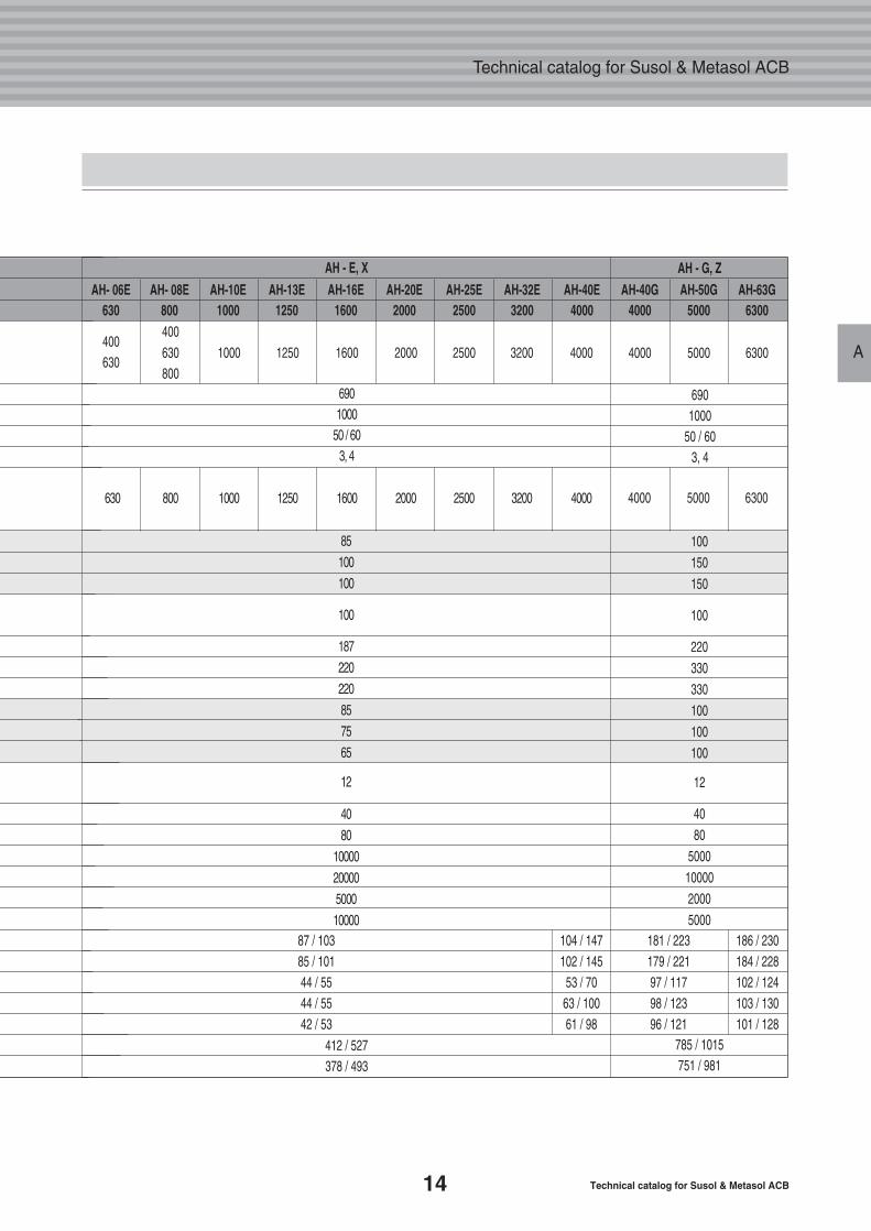
6901000
50 / 603, 4
6901000
50 / 603, 4
412 / 527378 / 493
785 / 1015751 / 981
87 / 103 104 / 14785 / 101 102 / 14544 / 55 53 / 7044 / 55 63 / 10042 / 53 61 / 98
181 / 223 186 / 230179 / 221 184 / 22897 / 117 102 / 12498 / 123 103 / 13096 / 121 101 / 128
400630 1000 1250 1600 2000 2500 3200 4000800
630 800 1000 1250 1600 2000 2500 3200 4000
400630
AH - E, X AH - G, ZAH- 06E AH- 08E AH-10E AH-13E AH-16E AH-20E AH-25E AH-32E AH-40E
630 800 1000 1250 1600 2000 2500 3200 4000AH-40G AH-50G AH-63G
4000 5000 6300
4000 5000 6300
4000 5000 6300
85
100
100
100
187
220
220
85
75
65
12
40
80
10000
20000
5000
10000
100
150
150
100
220
330
330
100
100
100
12
40
80
5000
10000
2000
5000
15
Overview
A
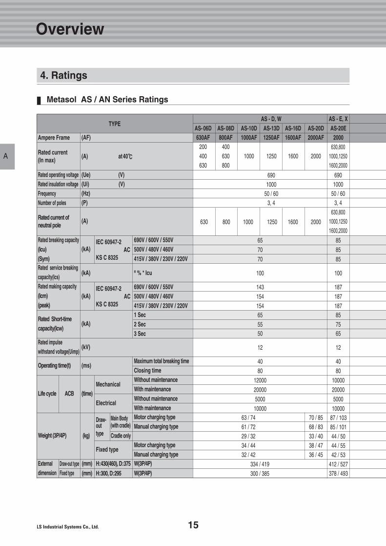
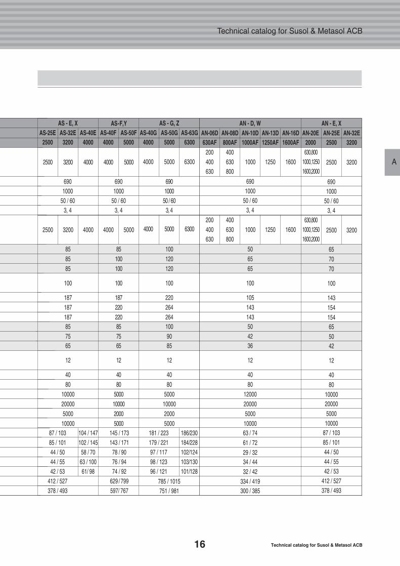
TYPEAS - D, W
Ampere Frame
Rated current(In max)
Rated current ofneutral pole
690V / 600V / 550V500V / 480V / 460V415V / 380V / 230V / 220V
690V / 600V / 550V500V / 480V / 460V415V / 380V / 230V / 220V1 Sec2 Sec3 Sec
Maximum total breaking timeClosing time
Motor charging typeManual charging type
Motor charging typeManual charging typeW(3P/4P)
W(3P/4P)
Without maintenanceWith maintenanceWithout maintenanceWith maintenance
Rated making capacity(Icm)(peak)
III % * Icu
Rated Short-time capacity(Icw)
Rated impulse withstand voltage(Uimp)
Operating time(t)
Life cycle
Weight (3P/4P)
Externaldimension
ACBMechanical
Electrical
Draw-outtype
Fixed type
Cradle only
Main Body(with cradle)
(AF)
(A) at40℃℃
(A)
(kA)IEC 60947-2
ACKS C 8325
IEC 60947-2AC
KS C 8325
(kA)
(kA)
(kA)
(kV)
(ms)
Draw-out typeFixed type
(mm)
(mm)H:430(460), D:375
H:300, D:295
(time)
(kg)
(Ue) (V)(Ui) (V)(Hz)(P)
6901000
50 / 603, 4
6901000
50 / 603, 4
65
70
70
100
143
154
15465
5550
12
40
80
12000
20000
5000
10000
334 / 419
300 / 385
63 / 74 70 / 8561 / 72 68 / 8329 / 32 33 / 4034 / 44 38 / 4732 / 42 36 / 45
87 / 10385 / 10144 / 5044 / 5542 / 53
412 / 527378 / 493
Rated operating voltageRated insulation voltageFrequencyNumber of poles
800 1000 1250 1600 2000630
630,8001000,12501600,2000
Rated breaking capacity(Icu)(Sym)Rated service breaking capacity(Ics)
AS - E, X
630,8001000,12501600,2000
85
85
85
100
187
187
18785
7565
12
40
80
10000
20000
5000
10000
AS- 06D AS- 08D AS-10D AS-13D AS-16D AS-20D AS-20E630AF 800AF 1000AF 1250AF 1600AF 2000AF 2000
200 400400 630 1000 1250 1600 2000630 800
Metasol AS / AN Series Ratings
4. Ratings
16 Technical catalog for Susol & Metasol ACB
Technical catalog for Susol & Metasol ACB
A
6901000
50 / 603, 4
6901000
50 / 603, 4
6901000
50 / 603, 4
6901000
50 / 603, 4
6901000
50 / 603, 4
785 / 1015751 / 981
87 / 103 104 / 147 145 / 17385 / 101 102 / 145 143 / 17144 / 50 58 / 70 78 / 9044 / 55 63 / 100 76 / 9442 / 53 61/ 98 74 / 92
412 / 527 629 / 799378 / 493 597/ 767
181 / 223 186/230179 / 221 184/22897 / 117 102/12498 / 123 103/13096 / 121 101/128
AS - E, X AS-F,Y AS - G, ZAS-25E AS-32E AS-40E AS-40F AS-50F
2500 3200 4000 4000 5000
2500 3200 4000 4000 5000
2500 3200 4000 4000 5000
AS-40G AS-50G AS-63G4000 5000 6300
4000 5000 6300630,800
1000,12501600,2000
AN-06D AN-08D AN-10D AN-13D AN-16D630AF 800AF 1000AF 1250AF 1600AF
2500 3200
AN-20E AN-25E AN-32E2000 2500 3200
4000 5000 6300
85
100
100
100
187
220
22085
7565
12
40
80
5000
10000
2000
5000
85
85
85
100
187
187
18785
7565
12
40
80
10000
20000
5000
10000
100
120
120
100
220
264
264100
9085
12
40
80
5000
10000
2000
5000
200 400400 630 1000 1250 1600630 800
630,8001000,12501600,2000
2500 3200
200 400400 630 1000 1250 1600630 800
AN - D, W AN - E, X
50
65
65
100
105
143
14350
4236
12
40
80
12000
20000
5000
1000063 / 74
61 / 72
29 / 3234 / 44
32 / 42
334 / 419300 / 385
65
70
70
100
143
154
15465
5042
12
40
80
1000020000
500010000
87 / 10385 / 10144 / 5044 / 5542 / 53
412 / 527378 / 493
17
Overview
A
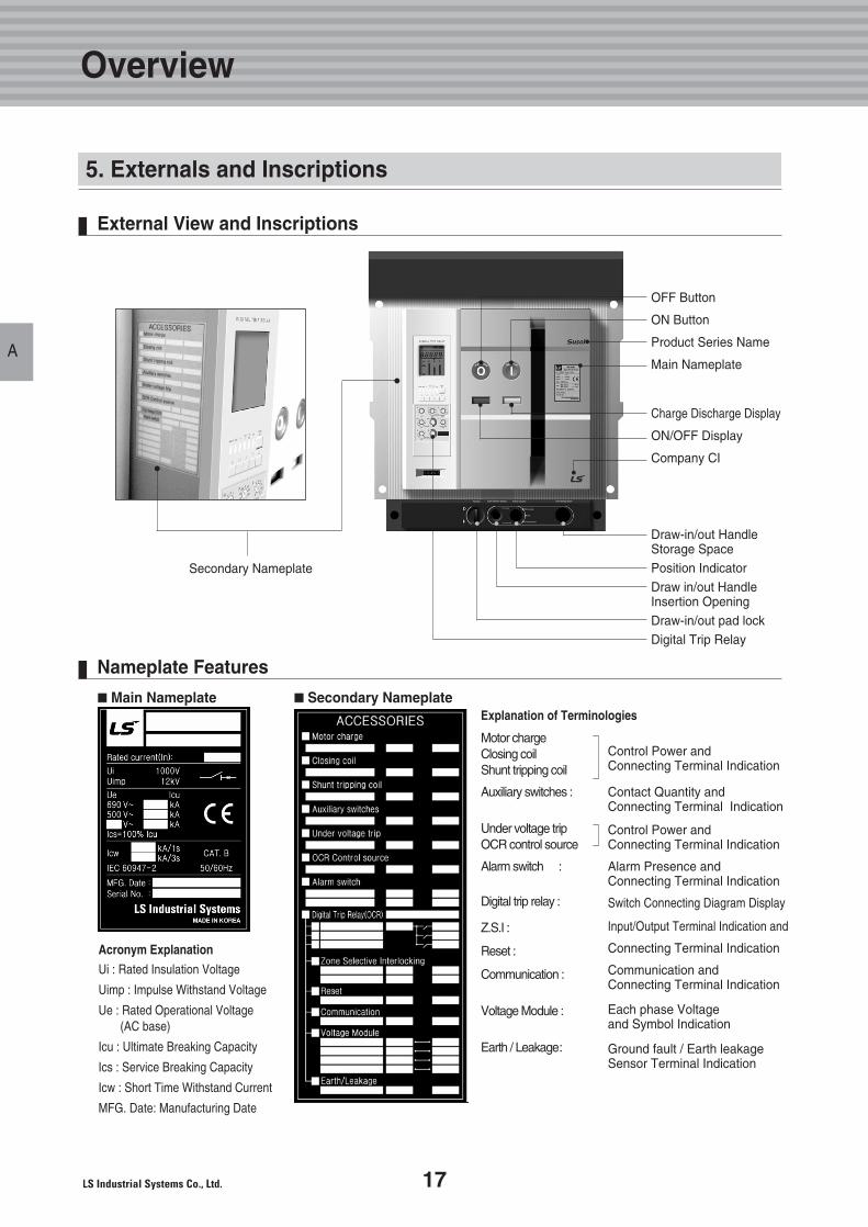
Ui : Rated Insulation Voltage
Uimp : Impulse Withstand Voltage
Ue : Rated Operational Voltage (AC base)
Icu : Ultimate Breaking Capacity
Ics : Service Breaking Capacity
Icw : Short Time Withstand Current
MFG. Date: Manufacturing Date
Acronym Explanation
■■Main Nameplate
Motor chargeClosing coilShunt tripping coil
Auxiliary switches :
Under voltage tripOCR control source
Alarm switch :
Digital trip relay :
Z.S.I :
Reset :
Communication :
Voltage Module :
Earth / Leakage:
Control Power andConnecting Terminal Indication
Contact Quantity and Connecting Terminal Indication
Control Power andConnecting Terminal Indication
Alarm Presence andConnecting Terminal Indication
Switch Connecting Diagram Display
Input/Output Terminal Indication and
Connecting Terminal Indication
Communication and Connecting Terminal Indication
Each phase Voltage and Symbol Indication
Ground fault / Earth leakageSensor Terminal Indication
Explanation of Terminologies■■Secondary Nameplate
Draw-in/out HandleStorage SpacePosition IndicatorDraw in/out HandleInsertion OpeningDraw-in/out pad lockDigital Trip Relay
Charge Discharge Display
ON/OFF Display
Company CI
OFF Button
ON Button
Product Series Name
Main Nameplate
Secondary Nameplate
External View and Inscriptions
Nameplate Features
5. Externals and Inscriptions
B.Structure and Operation
19
21
1. Internal Structure and Components
2. Basic Function and Breaking Operation
18 Technical catalog for Susol & Metasol ACB
Technical catalog for Susol & Metasol ACB
19
Structure and Operation
B
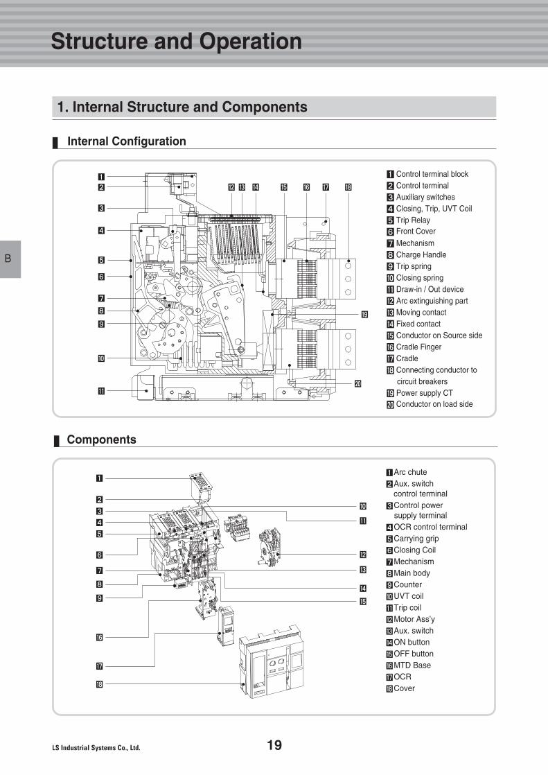
Components
�Arc chute�Aux. switch
control terminal�Control power
supply terminal�OCR control terminal�Carrying grip�Closing Coil�Mechanism�Main body�Counter�UVT coil�Trip coil�Motor Ass’y�Aux. switch�ON button�OFF button�MTD Base�OCR�Cover
�
�
�
�
�
�
�
�
�
�
�
�
�
�
�
�
�
Internal Configuration
1. Internal Structure and Components
�
�
� � � � � � �
�
�
�
�
�
�
�
�
�
�
�
�
� Control terminal block� Control terminal� Auxiliary switches� Closing, Trip, UVT Coil� Trip Relay� Front Cover� Mechanism� Charge Handle� Trip spring� Closing spring� Draw-in / Out device� Arc extinguishing part� Moving contact� Fixed contact� Conductor on Source side� Cradle Finger� Cradle� Connecting conductor to
circuit breakers� Power supply CT� Conductor on load side
20 Technical catalog for Susol & Metasol ACB
Technical catalog for Susol & Metasol ACB
B
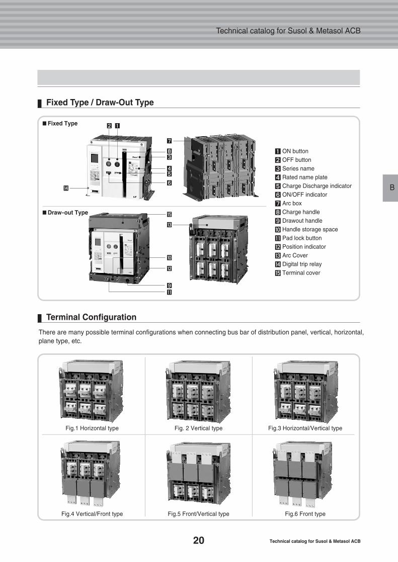
There are many possible terminal configurations when connecting bus bar of distribution panel, vertical, horizontal, plane type, etc.
� ON button� OFF button� Series name� Rated name plate� Charge Discharge indicator� ON/OFF indicator� Arc box� Charge handle� Drawout handle� Handle storage space� Pad lock button� Position indicator
� Arc Cover
� Digital trip relay
� Terminal cover
��
�
��
��
�
■Fixed Type
■Draw-out Type
Fig.1 Horizontal type Fig. 2 Vertical type Fig.3 Horizontal/Vertical type
Fig.4 Vertical/Front type Fig.5 Front/Vertical type Fig.6 Front type
�
�
�
�
�
�
�
Fixed Type / Draw-Out Type
Terminal Configuration
21
Structure and Operation
B
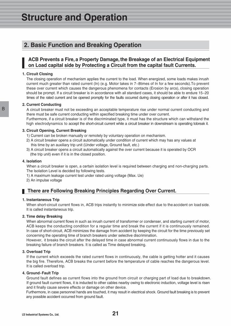
1. Circuit ClosingThe closing operation of mechanism applies the current to the load. When energized, some loads makes inrush current much greater than rated current (In) (e.g. Motor takes in 7~8times of In for a few seconds).To preventthese over current which causes the dangerous phenomena for contacts (Erosion by arcs), closing operationshould be prompt. If a circuit breaker is in accordance with all standard cases, it should be able to endure 15~20times of the rated current and be opened promptly for the faults occurred during closing operation or after it has closed.
2. Current ConductingA circuit breaker must not be exceeding an acceptable temperature rise under normal current conducting andthere must be safe current conducting within specified breaking time under over current.Furthermore, if a circuit breaker is of the discriminated type, it must has the structure which can withstand thehigh electrodynamics to accept the short-circuit current while a circuit breaker in downstream is operating tobreak it.
3. Circuit Opening, Current Breaking1) Current can be broken manually or remotely by voluntary operation on mechanism. 2) A circuit breaker opens a circuit automatically under condition of current which may has any values at
this time by an auxiliary trip unit (Under voltage, Ground fault, etc.)3) A circuit breaker opens a circuit automatically against the over current because it is operated by OCR
(the trip unit) even if it is in the closed position.
4. IsolationWhen a circuit breaker is open, a certain isolation level is required between charging and non-charging parts.The Isolation Level is decided by following tests.1) A maximum leakage current test under rated using voltage (Max. Ue) 2) An impulse voltage
1. Instantaneous TripWhen short-circuit current flows in, ACB trips instantly to minimize side effect due to the accident on load side.It is called instantaneous trip.
2. Time delay BreakingWhen abnormal current flows in such as inrush current of transformer or condenser, and starting current of motor, ACB keeps the conducting condition for a regular time and break the current if it is continuously remained.In case of short-circuit, ACB minimizes the damage from accident by keeping the circuit for the time previously setconcerning the operating time of branch breakers under selective discrimination. However, it breaks the circuit after the delayed time in case abnormal current continuously flows in due to thebreaking failure of branch breakers. It is called as Time delayed breaking.
3. Overload TripIf the current which exceeds the rated current flows in continuously, the cable is getting hotter and it causesthe big fire. Therefore, ACB breaks the current before the temperature of cable reaches the dangerous level.It is called overload trip.
4. Ground-Fault TripGround fault defines as current flows into the ground from circuit or charging part of load due to breakdown.If ground fault current flows, it is inducted to other cables nearby owing to electronic induction, voltage level is risenand it finally cause severe effects or damage on other device.Furthermore, in case personnel hands are touched, it may result in electrical shock. Ground fault breaking is to preventany possible accident occurred from ground fault.
ACB Prevents a Fire, a Property Damage, the Breakage of an Electrical Equipmenton Load capital side by Protecting a Circuit from the capital fault Currents.
2. Basic Function and Breaking Operation
There are Following Breaking Principles Regarding Over Current.
C.Internal Electrical Accessories
23
24
25
26
1. Closing & SHT Coil
2. Under Voltage TripDevice(UVT)
3. UVT Time Delay Controller
4. Trip Alarm Switch(AL)
22 Technical catalog for Susol & Metasol ACB
Technical catalog for Susol & Metasol ACB
23
Internal Electrical Accessories
C
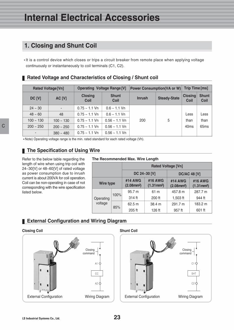
�It is a control device which closes or trips a circuit breaker from remote place when applying voltage
continuously or instantaneously to coil terminals (C1, C2).
Refer to the below table regarding the length of wire when using trip coil with24~30[V] or 48~60[V] of rated voltage as power consumption due to inrushcurrent is about 200VA for coil operation. Coil can be non-operating in case of notcorresponding with the wire specificationlisted below.
The Specification of Using Wire
Rated Voltage[Vn] Power Consumption(VA or W)Operating Voltage Range [V] Trip Time [ms]
ShuntCoil
ClosingCoil
ShuntCoil
ClosingCoil
24 ~ 30
48 ~ 60
100 ~ 130
200 ~ 250
-
-
48
100 ~ 130
200 ~ 250
380 ~ 480
0.75 ~ 1.1 Vn
0.75 ~ 1.1 Vn
0.75 ~ 1.1 Vn
0.75 ~ 1.1 Vn
0.75 ~ 1.1 Vn
0.6 ~ 1.1 Vn
0.6 ~ 1.1 Vn
0.56 ~ 1.1 Vn
0.56 ~ 1.1 Vn
0.56 ~ 1.1 Vn
200
�Note) Operating voltage range is the min. rated standard for each rated voltage (Vh).
The Recommended Max. Wire Length
Closing Coil Shunt Coil
5
Less
than
40ms
Less
than
65ms
DC [V] AC [V]
Wire type
100%
85%
#14 AWG(2.08mm2)
Operating voltage
95.7 m
314 ft
62.5 m
205 ft
Rated Voltage [Vn]
DC 24~30 [V] DC/AC 48 [V]
#16 AWG(1.31mm2)
61 m
200 ft
38.4 m
126 ft
#14 AWG(2.08mm2)
457.8 m
1,503 ft
291.7 m
957 ft
#16 AWG(1.31mm2)
287.7 m
944 ft
183.2 m
601 ft
Rated Voltage and Characteristics of Closing / Shunt coil
External Configuration and Wiring Diagram
Inrush Steady-State
External Configuration External ConfigurationWiring Diagram Wiring Diagram
1. Closing and Shunt Coil
24 Technical catalog for Susol & Metasol ACB
Technical catalog for Susol & Metasol ACB
C
External Configuration
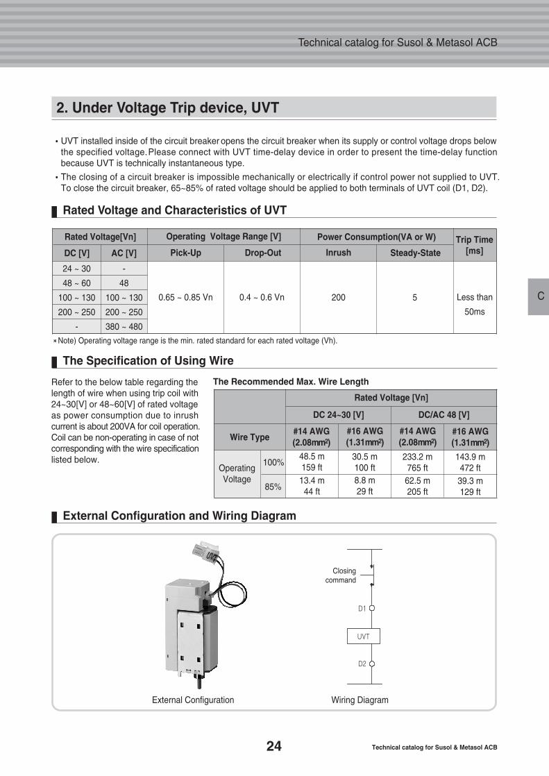
�UVT installed inside of the circuit breaker opens the circuit breaker when its supply or control voltage drops belowthe specified voltage.Please connect with UVT time-delay device in order to present the time-delay functionbecause UVT is technically instantaneous type.
�The closing of a circuit breaker is impossible mechanically or electrically if control power not supplied to UVT.To close the circuit breaker, 65~85% of rated voltage should be applied to both terminals of UVT coil (D1, D2).
Rated Voltage[Vn] Power Consumption(VA or W)Operating Voltage Range [V] Trip Time[ms]
24 ~ 30
48 ~ 60
100 ~ 130
200 ~ 250
-
0.65 ~ 0.85 Vn 0.4 ~ 0.6 Vn 200 5
�Note) Operating voltage range is the min. rated standard for each rated voltage (Vh).
Less than
50ms
DC [V]
-
48
100 ~ 130
200 ~ 250
380 ~ 480
AC [V] InrushDrop-OutPick-Up Steady-State
Refer to the below table regarding the length of wire when using trip coil with24~30[V] or 48~60[V] of rated voltage as power consumption due to inrushcurrent is about 200VA for coil operation. Coil can be non-operating in case of notcorresponding with the wire specificationlisted below.
The Specification of Using Wire
The Recommended Max. Wire Length
Wire Type
100%
85%
#14 AWG(2.08mm2)
Operating Voltage
48.5 m159 ft13.4 m44 ft
Rated Voltage [Vn]
DC 24~30 [V] DC/AC 48 [V]
#16 AWG(1.31mm2)
30.5 m100 ft8.8 m29 ft
#14 AWG(2.08mm2)
233.2 m765 ft62.5 m205 ft
#16 AWG(1.31mm2)
143.9 m472 ft39.3 m129 ft
Rated Voltage and Characteristics of UVT
External Configuration and Wiring Diagram
2. Under Voltage Trip device, UVT
Wiring Diagram
25
Internal Electrical Accessories
C
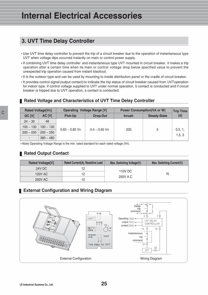
�Use UVT time delay controller to prevent the trip of a circuit breaker due to the operation of instantaneous typeUVT when voltage dips occurred instantly on main or control power supply.
�If combining UVT time delay controller and instantaneous type UVT mounted in circuit breaker, it makes a tripoperation after a certain time when its main or control voltage drop below specified value to prevent theunexpected trip operation caused from instant blackout.
�It is the outdoor type and can be used by mounting to inside distribution panel or the cradle of circuit breaker.
�It provides control signal (output contact) to indicate the trip status of circuit breaker caused from UVToperation for indoor type. If control voltage supplied to UVT under normal operation, b contact is conducted and if circuit breaker is tripped due to UVT operation, a contact is conducted.
Rated Voltage[Vn] Power Consumption(VA or W)Operating Voltage Range [V] Trip Time[s]
24 ~ 30
100 ~ 130
200 ~ 250
-
0.65 ~ 0.85 Vn 0.4 ~ 0.65 Vn 200 5
�Note) Operating Voltage Range is the min. rated standard for each rated voltage (Vh).
0.5, 1,
1.5, 3
DC [V]
48
100 ~ 130
200 ~ 250
380 ~ 480
AC [V] InrushPick-Up Drop-Out Steady-State
Rated Voltage and Characteristics of UVT Time Delay Controller
Rated Voltage[V] Rated Current(A), Resistive Load Max. Switching Voltage(V) Max. Switching Current(V)
24V DC
120V AC
250V AC
12
12
10
110V DC
250V A C15
Rated Output Contact
External Configuration and Wiring Diagram
3. UVT Time Delay Controller
External Configuration Wiring Diagram
26 Technical catalog for Susol & Metasol ACB
Technical catalog for Susol & Metasol ACB
C
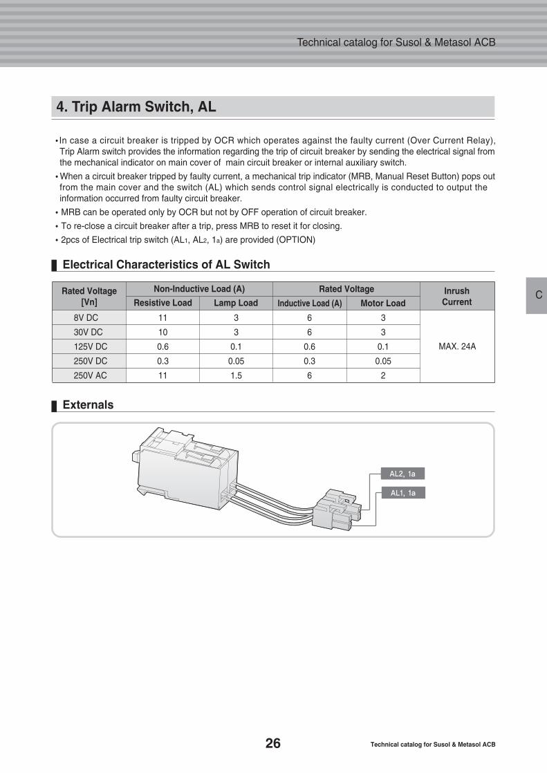
�In case a circuit breaker is tripped by OCR which operates against the faulty current (Over Current Relay),Trip Alarm switch provides the information regarding the trip of circuit breaker by sending the electrical signal fromthe mechanical indicator on main cover of main circuit breaker or internal auxiliary switch.
�When a circuit breaker tripped by faulty current, a mechanical trip indicator (MRB, Manual Reset Button) pops out from the main cover and the switch (AL) which sends control signal electrically is conducted to output theinformation occurred from faulty circuit breaker.
�MRB can be operated only by OCR but not by OFF operation of circuit breaker.
�To re-close a circuit breaker after a trip, press MRB to reset it for closing.
�2pcs of Electrical trip switch (AL1, AL2, 1a) are provided (OPTION)
4. Trip Alarm Switch, AL
Rated Voltage[Vn]
Non-Inductive Load (A) Rated Voltage Inrush Current
8V DC
30V DC
125V DC
250V DC
250V AC
11
10
0.6
0.3
11
3
3
0.1
0.05
1.5
6
6
0.6
0.3
6
3
3
0.1
0.05
2
MAX. 24A
Resistive Load Lamp Load Motor LoadInductive Load (A)
Electrical Characteristics of AL Switch
Externals
AL2, 1a
AL1, 1a
D.DigitalTrip Relay
28
29
31
32
44
53
1. Comparison Table upon Types
2. Externals and Configuration
3. Internal Circuit Diagram
4. Relay Function
5. Measurement Function
6. IO(Input-Output)Port
27
28 Technical catalog for Susol & Metasol ACB
Technical catalog for Susol & Metasol ACB
D
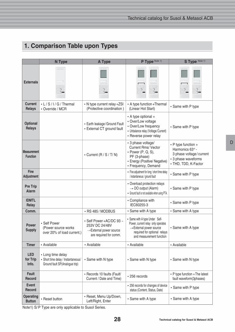
1. Comparison Table upon Types
N Type
Externals
CurrentRelays
�L / S / I / G / Thermal�Override / MCR
�N type current relay +ZSI (Protective coordination )
�Earth leakage/Ground Fault�External CT ground fault
�Current (R / S / T/ N)
�A type optional +�Over/Low voltage�Over/Low frequency�Unbalance relay (Voltage/Current)�Reverse power relay
�3 phase voltage/Current Rms/ Vector
�Power (P, Q, S), PF (3-phase)
�Energy (Positive/ Negative)�Frequency, Demand
�Fine adjustment for long / short time delay / instantaneous / ground fault
�Overload protection relaysDO output (Alarm)
�Ground fault is not available when using PTA.
�Compliance with IEC60255-3
�Same with A type
�Available�Available�Available
�Reset button
Note1) S/ P Type are only applicable to Susol Series.
�Reset, Menu Up/Down, Left/Right, Enter
�Records 10 faults (Fault/Current / Date and Time)
�Same with N type�Long time delay�Short time delay / Instantaneous/
Ground fault SP(Analogue trip)
�RS 485 / MODBUS
�Self Power +AC/DC 93 ~ 253V DC 24/48V
External power source are required for comm.
�Self Power(Power source works over 20% of load current.)
�Same with N type
�256 records
�256 records for changes of device status (Content, Status, Date)
�Same with A type
�Same with A type Under Self- Power, current relay only operates
External power source required for optional relays and measurement function
�A type function +Thermal (Linear Hot Start) �Same with P type
�Same with P type
�Same with P type
�Same with P type
�Same with P type
�Same with A type
�Same with P type
�P type function +The latest fault waveform(3phases)
�Same with A type
�Same with A type
�Available
�Same with N type
�P type function + Harmonics 63rd - 3 phase voltage/ current
�3 phase waveforms �THD, TDD, K-Factor
OptionalRelays
MeasurementFunction
FineAdjustment
IDMTLRelay
Comm.
Timer
PowerSupply
LED for Trip
Info.
FaultRecord
EventRecord
OperatingButton
Pre TripAlarm
A Type P Type
D
Note 1) Note 1)S Type
29
D
Digital Trip Relay
D
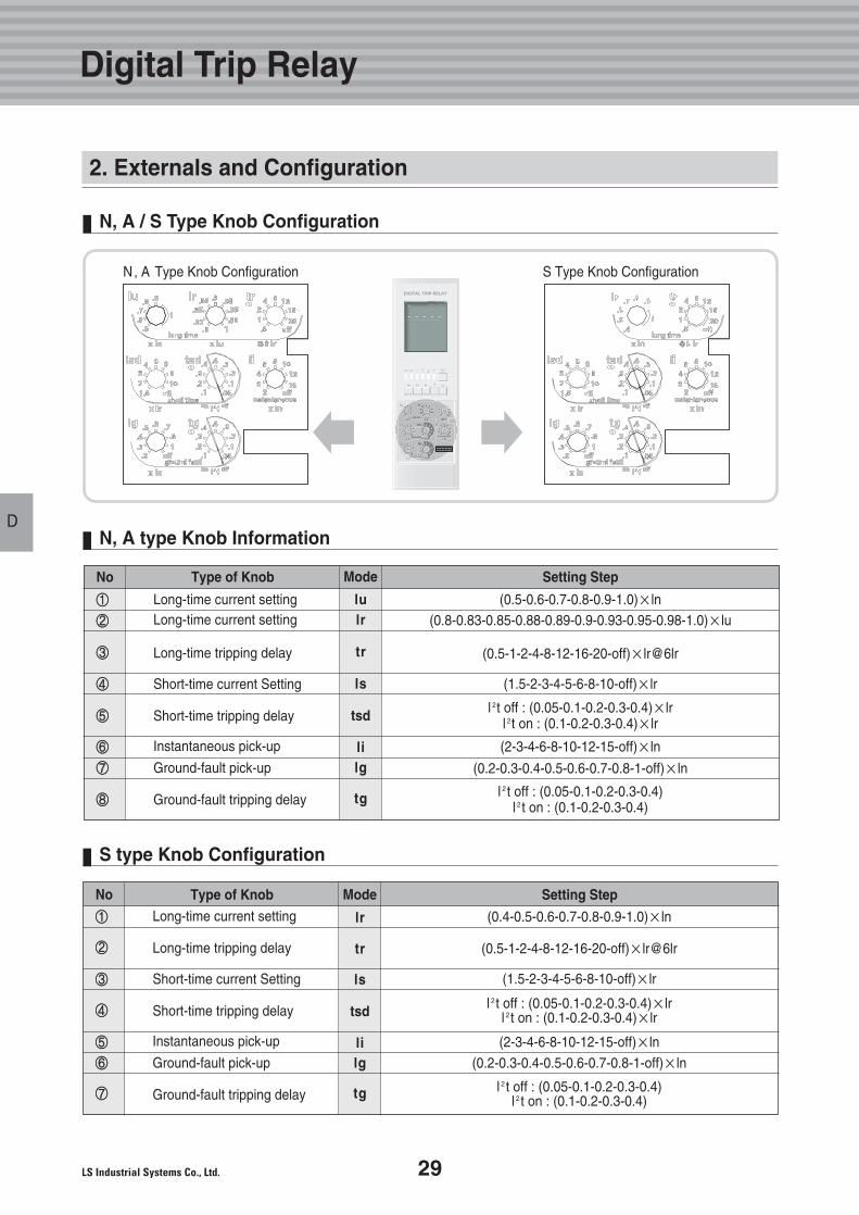
(0.4-0.5-0.6-0.7-0.8-0.9-1.0)×ln
(0.5-1-2-4-8-12-16-20-off)×lr@6lr
(1.5-2-3-4-5-6-8-10-off)×lr
l 2 t off : (0.05-0.1-0.2-0.3-0.4)×lrl 2 t on : (0.1-0.2-0.3-0.4)×lr
(2-3-4-6-8-10-12-15-off)×ln
(0.2-0.3-0.4-0.5-0.6-0.7-0.8-1-off)×ln
l 2t off : (0.05-0.1-0.2-0.3-0.4)l 2t on : (0.1-0.2-0.3-0.4)
(0.5-0.6-0.7-0.8-0.9-1.0)×ln(0.8-0.83-0.85-0.88-0.89-0.9-0.93-0.95-0.98-1.0)×lu
(0.5-1-2-4-8-12-16-20-off)×lr@6lr
(1.5-2-3-4-5-6-8-10-off)×lr
l 2t off : (0.05-0.1-0.2-0.3-0.4)×lrl 2t on : (0.1-0.2-0.3-0.4)×lr
(2-3-4-6-8-10-12-15-off)×ln
(0.2-0.3-0.4-0.5-0.6-0.7-0.8-1-off)×ln
l 2t off : (0.05-0.1-0.2-0.3-0.4)l 2t on : (0.1-0.2-0.3-0.4)
2. Externals and Configuration
N, A type Knob Information
N, A / S Type Knob Configuration
S type Knob Configuration
①①
②②
③③
④④
⑤⑤
⑥⑥
⑦⑦
⑧⑧
lulr
tr
ls
tsd
lilg
tg
No ModeType of Knob Setting Step
Long-time current settingLong-time current setting
Long-time tripping delay
Short-time current Setting
Short-time tripping delay
Instantaneous pick-up
Ground-fault pick-up
Ground-fault tripping delay
①①
②②
③③
④④
⑤⑤
⑥⑥
⑦⑦
lr
tr
ls
tsd
lilg
tg
No ModeType of Knob Setting StepLong-time current setting
Long-time tripping delay
Short-time current Setting
Short-time tripping delay
Instantaneous pick-up
Ground-fault pick-up
Ground-fault tripping delay
N, A Type Knob Configuration S Type Knob Configuration
� �
30 Technical catalog for Susol & Metasol ACB
Technical catalog for Susol & Metasol ACB
DD
ⓐⓐ
ⓑⓑ
ⓒⓒ
ⓓⓓ
ⓔⓔ
ⓕⓕ
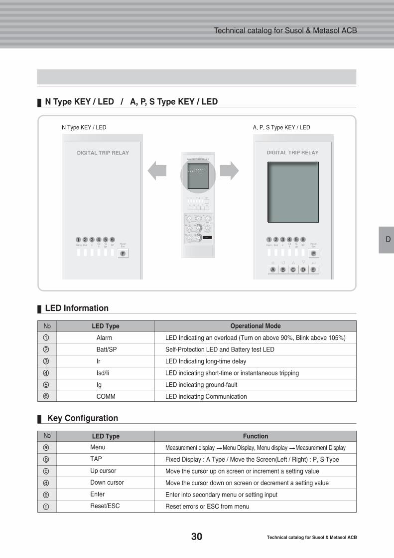
No LED Type Function
Menu
TAP
Up cursor
Down cursor
Enter
Reset/ESC
Measurement display Menu Display, Menu display Measurement Display
Fixed Display : A Type / Move the Screen(Left / Right) : P, S Type
Move the cursor up on screen or increment a setting value
Move the cursor down on screen or decrement a setting value
Enter into secondary menu or setting input
Reset errors or ESC from menu
LED Information
Key Configuration
①①
②②
③③
④④
⑤⑤
⑥⑥
No Operational Mode
Alarm
Batt/SP
Ir
Isd/Ii
Ig
COMM
LED Indicating an overload (Turn on above 90%, Blink above 105%)
Self-Protection LED and Battery test LED
LED Indicating long-time delay
LED indicating short-time or instantaneous tripping
LED indicating ground-fault
LED indicating Communication
LED Type
N Type KEY / LED / A, P, S Type KEY / LED
N Type KEY / LED A, P, S Type KEY / LED
� �
31
D
Digital Trip Relay
D
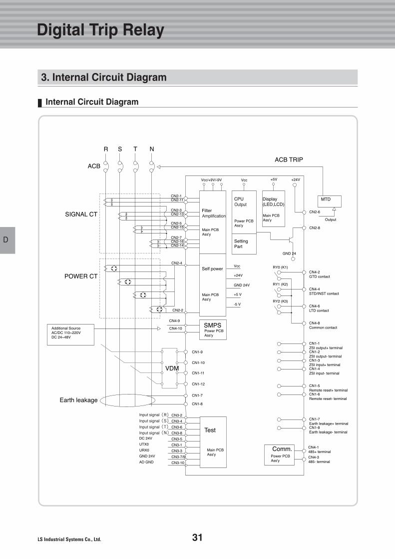
3. Internal Circuit Diagram
Internal Circuit Diagram
32 Technical catalog for Susol & Metasol ACB
Technical catalog for Susol & Metasol ACB
DD
4. Relay Function
Long- Time Delay Relays
Long-Time
Delay(L)
Short-Time
Delay(S)
Instantaneous(I)
Ground
Fault
Maximum time delay(sec)Accuracy:±15% or below 100ms
Continuous Thermal Memory Time
Current Setting(A)Accuracy:±10% or below 50ms
Maximum time delay(s)@ 10× Ir
Current Setting(A)Tripping time
Current Setting(A)Accuracy:±10%(Ig≥0.4In)±20%(Ig≥0.4In) or below 50ms
Maximum time delay(s)@ 1× In
tr @ (1.5× Ir)tr @ (6.0× Ir)tr @ (7.2× Ir)
Isd=Ir× ...
Tsd
Ii= In× ...
Ig=In× ...
tg
12.50.50.34
1.5
0.05
20
80
2
0.2
0.05
20
80
251
0.69
2
0.10.1
80
140
3
0.3
0.10.1
80
140
502
1.38
3
0.20.2
160
240
4
0.4
0.20.2
160
240
1004
2.7
4
0.30.3
260
340
6
0.5
0.30.3
260
340
2008
5.5
5
0.40.4
360
440
8
0.6
0.40.4
360
440
300128.3
6
10
0.7
4001611
8
12
0.8
50020
13.8
10
15
1.0
offoffoff
off
off
off
I2T offI2T onMin. TripTime(ms)Max. TripTime(ms)
I2t offI2t onMin. TripTime(ms)Max. TripTime(ms)
Current Setting(A) (1.15×× Ir) Ir = In ×× ... 0.4 0.5 0.6 0.7 0.8 0.9 1.0
below 50ms
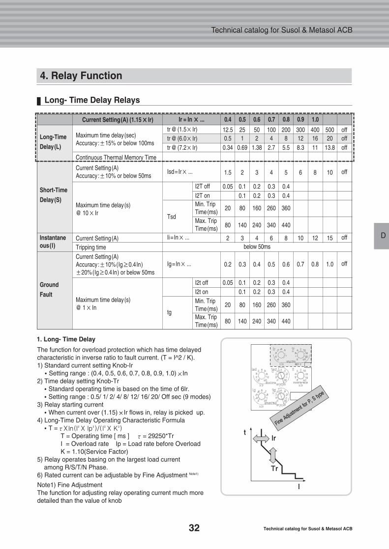
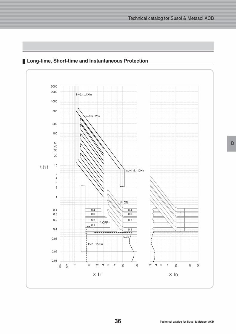
1. Long- Time Delay
The function for overload protection which has time delayed characteristic in inverse ratio to fault current. (T = I^2 / K). 1) Standard current setting Knob-Ir�Setting range : (0.4, 0.5, 0.6, 0.7, 0.8, 0.9, 1.0) In
2) Time delay setting Knob-Tr�Standard operating time is based on the time of 6lr. �Setting range : 0.5/ 1/ 2/ 4/ 8/ 12/ 16/ 20/ Off sec (9 modes)
3) Relay starting current �When current over (1.15) Ir flows in, relay is picked up.
4) Long-Time Delay Operating Characteristic Formula�T = τXln(I X Ip )/(I X K )
T = Operating time [ ms ] τ= 29250*TrI = Overload rate Ip = Load rate before OverloadK = 1.10(Service Factor)
5) Relay operates basing on the largest load current among R/S/T/N Phase.
6) Rated current can be adjustable by Fine Adjustment Note1)
Note1) Fine AdjustmentThe function for adjusting relay operating current much moredetailed than the value of knob
2 2 2 2
33
D
Digital Trip Relay
D
4. Relay Function
Short-Time Delay Relays
Long-Time
Delay(L)
Short-Time
Delay(S)
Instantaneous(I)
Ground
Fault
Maximum time delay(sec)Accuracy:±15% or below 100ms
Continuous Thermal Memory Time
Current Setting(A)Accuracy:±10% or below 50ms
Maximum time delay(s)@ 10× Ir
Current Setting(A)Tripping time
Current Setting(A)Accuracy:±10%(Ig≥0.4In)±20%(Ig≥0.4In) or below 50ms
Maximum time delay(s)@ 1× In
tr @ (1.5× Ir)tr @ (6.0× Ir)tr @ (7.2× Ir)
Isd=Ir× ...
Tsd
Ii= In× ...
Ig=In× ...
tg
12.50.50.34
1.5
0.05
20
80
2
0.2
0.05
20
80
251
0.69
2
0.10.1
80
140
3
0.3
0.10.1
80
140
502
1.38
3
0.20.2
160
240
4
0.4
0.20.2
160
240
1004
2.7
4
0.30.3
260
340
6
0.5
0.30.3
260
340
2008
5.5
5
0.40.4
360
440
8
0.6
0.40.4
360
440
300128.3
6
10
0.7
4001611
8
12
0.8
50020
13.8
10
15
1.0
offoffoff
off
off
off
I2T offI2T onMin. TripTime(ms)Max. TripTime(ms)
I2t offI2t onMin. TripTime(ms)Max. TripTime(ms)
Current Setting(A) (1.15×× Ir) Ir = In ×× ... 0.4 0.5 0.6 0.7 0.8 0.9 1.0
below 50ms
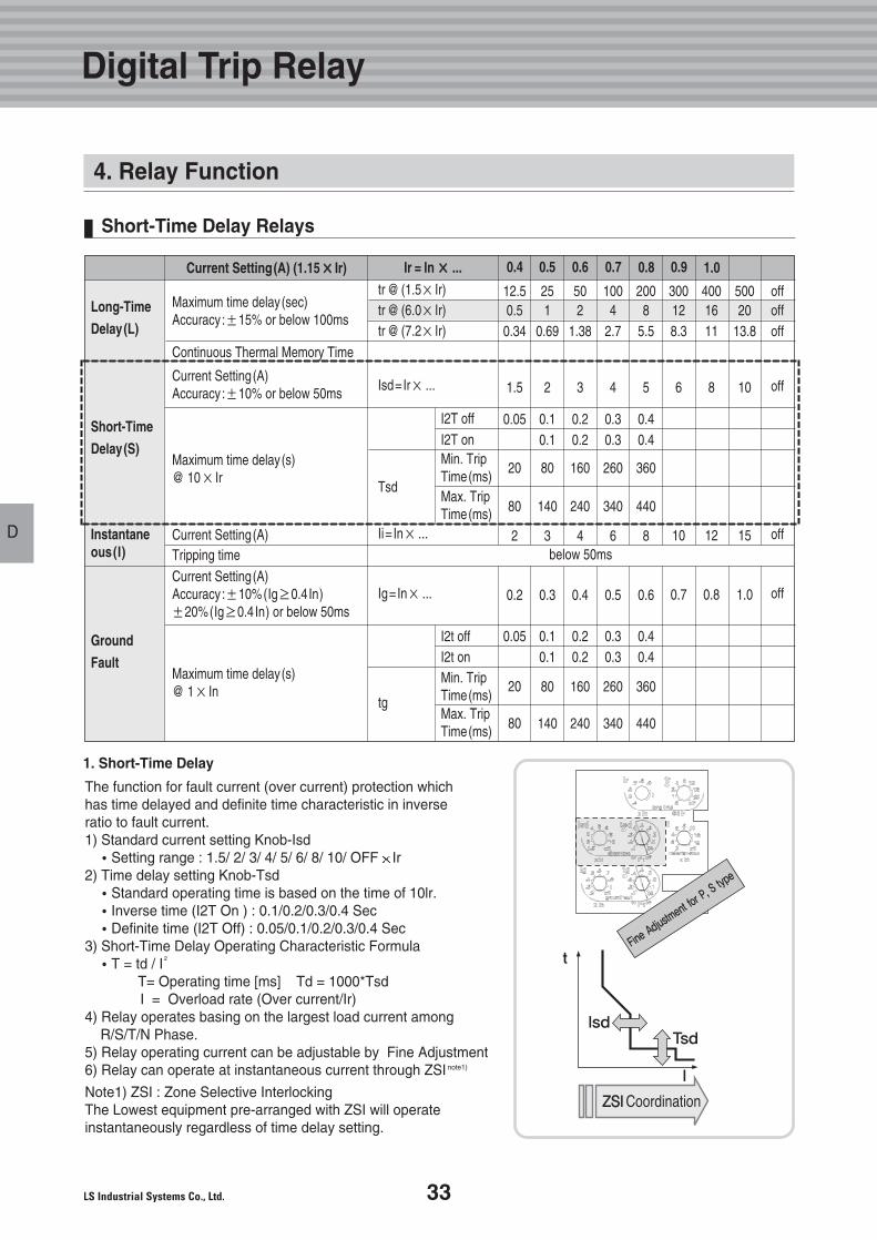
The function for fault current (over current) protection which has time delayed and definite time characteristic in inverse ratio to fault current.1) Standard current setting Knob-Isd�Setting range : 1.5/ 2/ 3/ 4/ 5/ 6/ 8/ 10/ OFF Ir
2) Time delay setting Knob-Tsd�Standard operating time is based on the time of 10lr. �Inverse time (I2T On ) : 0.1/0.2/0.3/0.4 Sec�Definite time (I2T Off) : 0.05/0.1/0.2/0.3/0.4 Sec
3) Short-Time Delay Operating Characteristic Formula�T = td / I
T= Operating time [ms] Td = 1000*TsdI = Overload rate (Over current/Ir)
4) Relay operates basing on the largest load current among R/S/T/N Phase.
5) Relay operating current can be adjustable by Fine Adjustment6) Relay can operate at instantaneous current through ZSI note1)
Note1) ZSI : Zone Selective InterlockingThe Lowest equipment pre-arranged with ZSI will operate instantaneously regardless of time delay setting.
1. Short-Time Delay
2
34 Technical catalog for Susol & Metasol ACB
Technical catalog for Susol & Metasol ACB
DD
Instantaneous
Long-Time
Delay(L)
Short-Time
Delay(S)
Instantaneous(I)
Ground
Fault
Maximum time delay(sec)Accuracy:±15% or below 100ms
Continuous Thermal Memory Time
Current Setting(A)Accuracy:±10% or below 50ms
Maximum time delay(s)@ 10× Ir
Current Setting(A)Tripping time
Current Setting(A)Accuracy:±10%(Ig≥0.4In)±20%(Ig≥0.4In) or below 50ms
Maximum time delay(s)@ 1× In
tr @ (1.5× Ir)tr @ (6.0× Ir)tr @ (7.2× Ir)
Isd=Ir× ...
Tsd
Ii= In× ...
Ig=In× ...
tg
12.50.50.34
1.5
0.05
20
80
2
0.2
0.05
20
80
251
0.69
2
0.10.1
80
140
3
0.3
0.10.1
80
140
502
1.38
3
0.20.2
160
240
4
0.4
0.20.2
160
240
1004
2.7
4
0.30.3
260
340
6
0.5
0.30.3
260
340
2008
5.5
5
0.40.4
360
440
8
0.6
0.40.4
360
440
300128.3
6
10
0.7
4001611
8
12
0.8
50020
13.8
10
15
1.0
offoffoff
off
off
off
I2T offI2T onMin. TripTime(ms)Max. TripTime(ms)
I2t offI2t onMin. TripTime(ms)Max. TripTime(ms)
Current Setting(A) (1.15×× Ir) Ir = In ×× ... 0.4 0.5 0.6 0.7 0.8 0.9 1.0
below 50ms
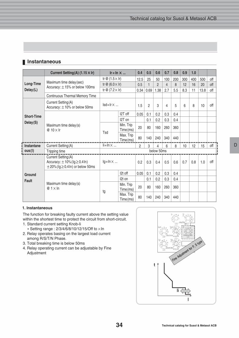
The function for breaking faulty current above the setting valuewithin the shortest time to protect the circuit from short-circuit.1. Standard current setting Knob-Ii�Setting range : 2/3/4/6/8/10/12/15/Off to In
2. Relay operates basing on the largest load current among R/S/T/N Phase.
3. Total breaking time is below 50ms4. Relay operating current can be adjustable by Fine
Adjustment
1. Instantaneous
35
D
Digital Trip Relay
D
4. Relay Function
Ground Fault
Long-Time
Delay(L)
Short-Time
Delay(S)
Instantaneous(I)
Ground
Fault
Maximum time delay(sec)Accuracy:±15% or below 100ms
Continuous Thermal Memory Time
Current Setting(A)Accuracy:±10% or below 50ms
Maximum time delay(s)@ 10× Ir
Current Setting(A)Tripping time
Current Setting(A)Accuracy:±10%(Ig≥0.4In)±20%(Ig≥0.4In) or below 50ms
Maximum time delay(s)@ 1× In
tr @ (1.5× Ir)tr @ (6.0× Ir)tr @ (7.2× Ir)
Isd=Ir× ...
Tsd
Ii= In× ...
Ig=In× ...
tg
12.50.50.34
1.5
0.05
20
80
2
0.2
0.05
20
80
251
0.69
2
0.10.1
80
140
3
0.3
0.10.1
80
140
502
1.38
3
0.20.2
160
240
4
0.4
0.20.2
160
240
1004
2.7
4
0.30.3
260
340
6
0.5
0.30.3
260
340
2008
5.5
5
0.40.4
360
440
8
0.6
0.40.4
360
440
300128.3
6
10
0.7
4001611
8
12
0.8
50020
13.8
10
15
1.0
offoffoff
off
off
off
I2T offI2T onMin. TripTime(ms)Max. TripTime(ms)
I2t offI2t onMin. TripTime(ms)Max. TripTime(ms)
Current Setting(A) (1.15×× Ir) Ir = In ×× ... 0.4 0.5 0.6 0.7 0.8 0.9 1.0
below 50ms
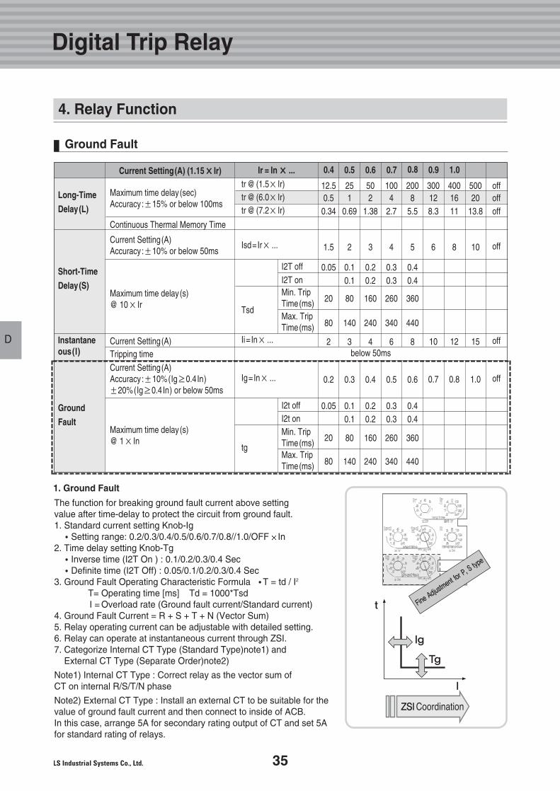
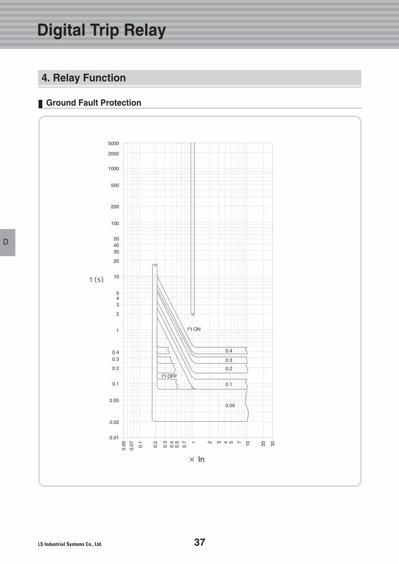
The function for breaking ground fault current above setting value after time-delay to protect the circuit from ground fault. 1. Standard current setting Knob-Ig�Setting range: 0.2/0.3/0.4/0.5/0.6/0.7/0.8//1.0/OFF In
2. Time delay setting Knob-Tg�Inverse time (I2T On ) : 0.1/0.2/0.3/0.4 Sec�Definite time (I2T Off) : 0.05/0.1/0.2/0.3/0.4 Sec
3. Ground Fault Operating Characteristic Formula �T = td / I2
T= Operating time [ms] Td = 1000*TsdI = Overload rate (Ground fault current/Standard current)
4. Ground Fault Current = R + S + T + N (Vector Sum)5. Relay operating current can be adjustable with detailed setting.6. Relay can operate at instantaneous current through ZSI.7. Categorize Internal CT Type (Standard Type)note1) and
External CT Type (Separate Order)note2)
Note1) Internal CT Type : Correct relay as the vector sum of CT on internal R/S/T/N phase
Note2) External CT Type : Install an external CT to be suitable for thevalue of ground fault current and then connect to inside of ACB.In this case, arrange 5A for secondary rating output of CT and set 5Afor standard rating of relays.
1. Ground Fault
36 Technical catalog for Susol & Metasol ACB
Technical catalog for Susol & Metasol ACB
DD
Long-time, Short-time and Instantaneous Protection
37
D
Digital Trip Relay
D
Ground Fault Protection
4. Relay Function
38 Technical catalog for Susol & Metasol ACB
Technical catalog for Susol & Metasol ACB
DD
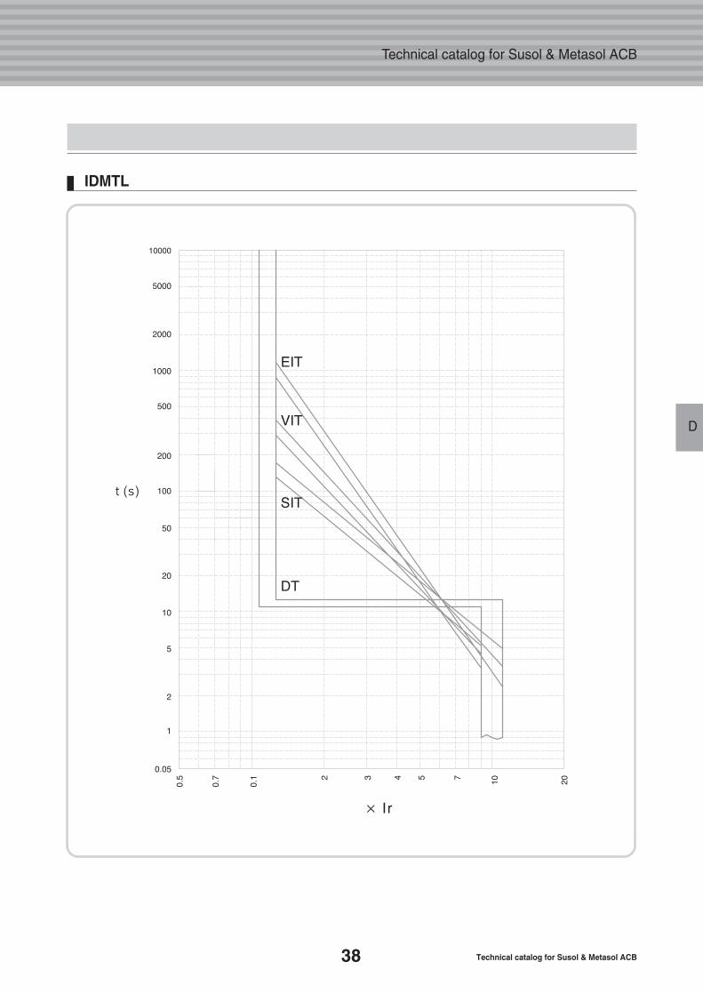
IDMTL
39
D
Digital Trip Relay
D
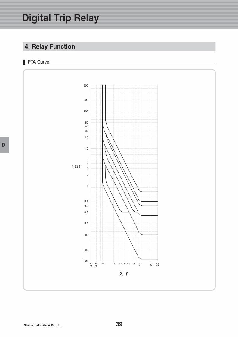
PTA Curve
4. Relay Function
40 Technical catalog for Susol & Metasol ACB
Technical catalog for Susol & Metasol ACB
D
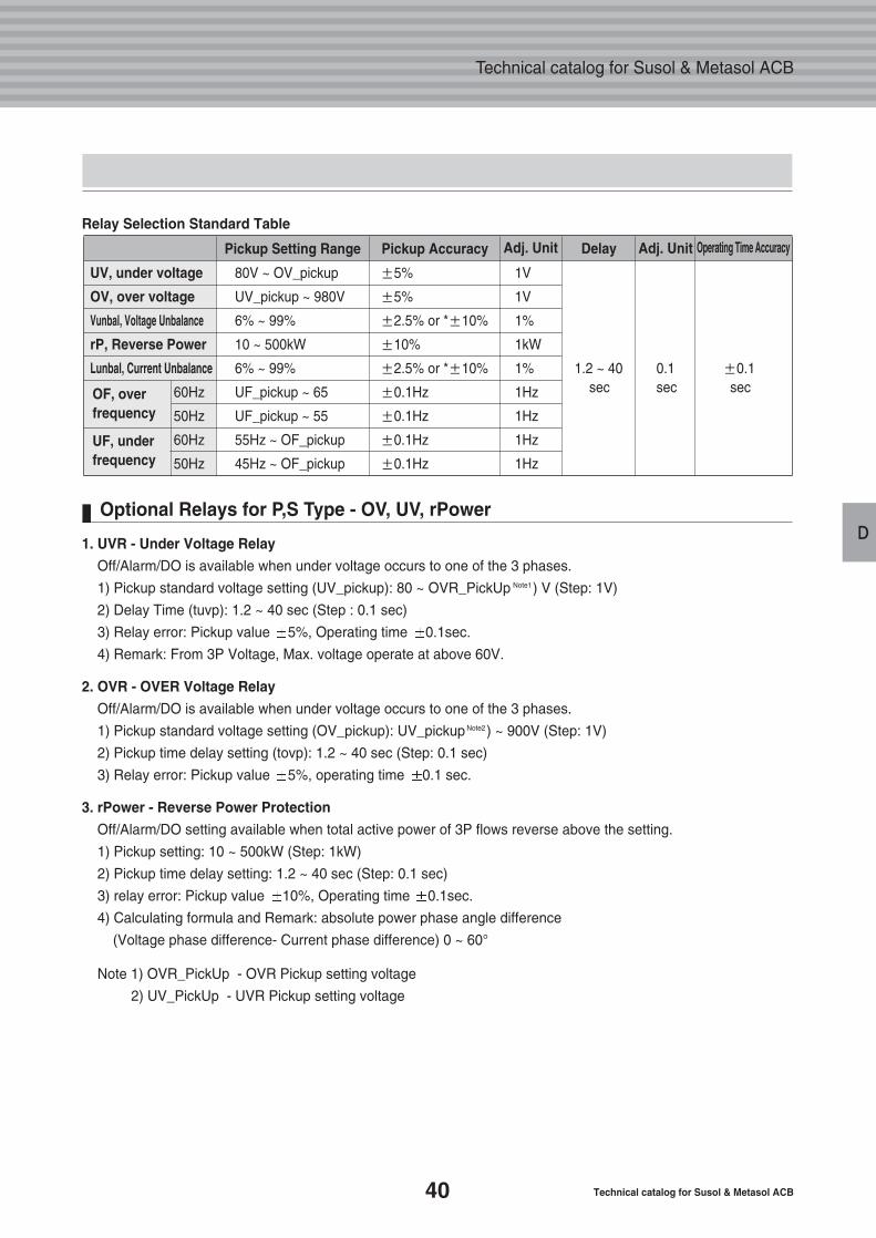
UV, under voltage 80V ~ OV_pickup ±5% 1V
OV, over voltage UV_pickup ~ 980V ±5% 1V
Vunbal, Voltage Unbalance 6% ~ 99% ±2.5% or *±10% 1%
rP, Reverse Power 10 ~ 500kW ±10% 1kW
Lunbal, Current Unbalance 6% ~ 99% ±2.5% or *±10% 1% 1.2 ~ 40 0.1 ±0.1
60Hz UF_pickup ~ 65 ±0.1Hz 1Hz sec sec sec
50Hz UF_pickup ~ 55 ±0.1Hz 1Hz
60Hz 55Hz ~ OF_pickup ±0.1Hz 1Hz
50Hz 45Hz ~ OF_pickup ±0.1Hz 1Hz
OF, over frequency
UF, underfrequency
1. UVR - Under Voltage Relay
Off/Alarm/DO is available when under voltage occurs to one of the 3 phases.
1) Pickup standard voltage setting (UV_pickup): 80 ~ OVR_PickUp Note1) V (Step: 1V)
2) Delay Time (tuvp): 1.2 ~ 40 sec (Step : 0.1 sec)
3) Relay error: Pickup value 5%, Operating time 0.1sec.
4) Remark: From 3P Voltage, Max. voltage operate at above 60V.
2. OVR - OVER Voltage Relay
Off/Alarm/DO is available when under voltage occurs to one of the 3 phases.
1) Pickup standard voltage setting (OV_pickup): UV_pickup Note2) ~ 900V (Step: 1V)
2) Pickup time delay setting (tovp): 1.2 ~ 40 sec (Step: 0.1 sec)
3) Relay error: Pickup value 5%, operating time 0.1 sec.
3. rPower - Reverse Power Protection
Off/Alarm/DO setting available when total active power of 3P flows reverse above the setting.
1) Pickup setting: 10 ~ 500kW (Step: 1kW)
2) Pickup time delay setting: 1.2 ~ 40 sec (Step: 0.1 sec)
3) relay error: Pickup value 10%, Operating time 0.1sec.
4) Calculating formula and Remark: absolute power phase angle difference
(Voltage phase difference- Current phase difference) 0 ~ 60°
Note 1) OVR_PickUp - OVR Pickup setting voltage
2) UV_PickUp - UVR Pickup setting voltage
Relay Selection Standard Table
Optional Relays for P,S Type - OV, UV, rPower
DelayPickup AccuracyPickup Setting Range Operating Time AccuracyAdj. UnitAdj. Unit
41
D
4. Relay Function
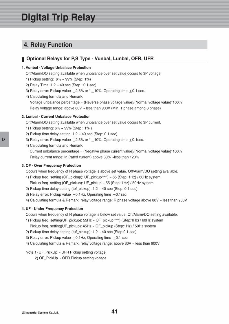
Optional Relays for P,S Type - Vunbal, Lunbal, OFR, UFR
1. Vunbal - Voltage Unbalace Protection
Off/Alarm/DO setting available when unbalance over set value occurs to 3P voltage.
1) Pickup setting: 6% ~ 99% (Step: 1%)
2) Delay Time: 1.2 ~ 40 sec (Step : 0.1 sec)
3) Relay error: Pickup value 2.5% or * 10%, Operating time 0.1 sec.
4) Calculating formula and Remark:
Voltage unbalance percentage = (Reverse phase voltage value)/(Normal voltage value)*100%
Relay voltage range: above 80V ~ less than 900V (Min. 1 phase among 3 phase)
2. Lunbal - Current Unbalace Protection
Off/Alarm/DO setting available when unbalance over set value occurs to 3P current.
1) Pickup setting: 6% ~ 99% (Step : 1% )
2) Pickup time delay setting: 1.2 ~ 40 sec (Step: 0.1 sec)
3) Relay error: Pickup value 2.5% or * 10%, Operating time 0.1sec.
4) Calculating formula and Remark:
Current unbalance percentage = (Negative phase current value)/(Normal voltage value)*100%
Relay current range: In (rated current) above 30% ~less than 120%
3. OF - Over Frequency Protection
Occurs when frequency of R phase voltage is above set value. Off/Alarm/DO setting available.
1) Pickup freq. setting (OF_pickup): UF_pickup Note1) ~ 65 (Step: 1Hz) / 60Hz system
Pickup freq. setting (OF_pickup): UF_pickup ~ 55 (Step: 1Hz) / 50Hz system
2) Pickup time delay setting (tof_pickup): 1.2 ~ 40 sec (Step: 0.1 sec)
3) Relay error: Pickup value 0.1Hz, Operating time 0.1sec
4) Calculating formula & Remark: relay voltage range: R phase voltage above 80V ~ less than 900V
4. UF - Under Frequency Protection
Occurs when frequency of R phase voltage is below set value. Off/Alarm/DO setting available.
1) Pickup freq. setting(UF_pickup): 55Hz ~ OF_pickup Note2) (Step:1Hz) / 60Hz system
Pickup freq. setting(UF_pickup): 45Hz ~ OF_pickup (Step:1Hz) / 50Hz system
2) Pickup time delay setting (tuf_pickup): 1.2 ~ 40 sec (Step:0.1 sec)
3) Relay error: Pickup value 0.1Hz, Operating time 0.1 sec
4) Calculating formula & Remark: relay voltage range: above 80V ~ less than 900V
Note 1) UF_PickUp - UFR Pickup setting voltage
2) OF_PickUp - OFR Pickup setting voltage
Digital Trip Relay
42 Technical catalog for Susol & Metasol ACB
Technical catalog for Susol & Metasol ACB
D
R S T N
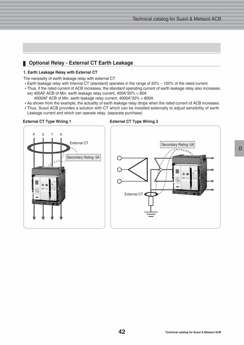
Optional Relay - External CT Earth Leakage
1. Earth Leakage Relay with External CT
The necessity of earth leakage relay with external CTEarth leakage relay with Internal CT (standard) operates in the range of 20% ~ 100% of the rated current.Thus, if the rated current of ACB increases, the standard operating current of earth leakage relay also increases.ex) 400AF ACB of Min. earth leakage relay current, 400A*20% = 80A
4000AF ACB of Min. earth leakage relay current, 4000A*20% = 800A As shown from the example, the actuality of earth leakage relay drops when the rated current of ACB increases.Thus, Susol ACB provides a solution with CT which can be installed externally to adjust sensibility of earth Leakage current and which can operate relay. (separate purchase)
External CT Type Wiring 1
External CT
External CT
External CT Type Wiring 2
Secondary Rating: 5A
Secondary Rating:5A
43
D
R S T N
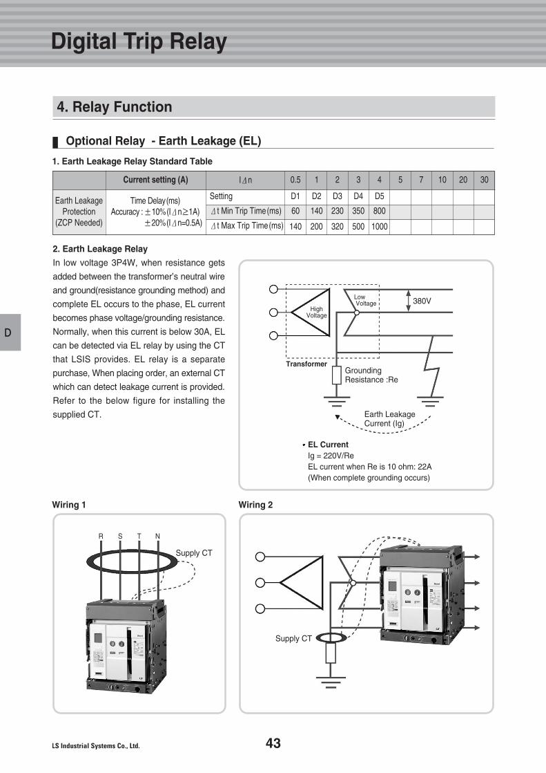
EL CurrentIg = 220V/ReEL current when Re is 10 ohm: 22A(When complete grounding occurs)
High Voltage
TransformerGrounding Resistance :Re
Earth Leakage Current (Ig)
Low Voltage 380V
Supply CT
Supply CT
2. Earth Leakage Relay
In low voltage 3P4W, when resistance gets
added between the transformer’s neutral wire
and ground(resistance grounding method) and
complete EL occurs to the phase, EL current
becomes phase voltage/grounding resistance.
Normally, when this current is below 30A, EL
can be detected via EL relay by using the CT
that LSIS provides. EL relay is a separate
purchase, When placing order, an external CT
which can detect leakage current is provided.
Refer to the below figure for installing the
supplied CT.
Wiring 1 Wiring 2
Digital Trip Relay
4. Relay Function
Optional Relay - Earth Leakage (EL)
Earth Leakage Protection
(ZCP Needed)
Time Delay(ms)Accuracy :±10%(IΔn≥1A)
±20%(IΔn=0.5A)
Setting
Δt Min Trip Time(ms)
Δt Max Trip Time(ms)
D2
140
200
D1
60
140
D3
230
320
D4
350
500
D5
800
1000
Current setting (A) IΔn 10.5 2 3 4 5 7 10 20 30
1. Earth Leakage Relay Standard Table
44 Technical catalog for Susol & Metasol ACB
Technical catalog for Susol & Metasol ACB
D
F/S
F/S
F/S
3P3W
3P4W
3P4W
F/S
F/S
F/S
F/S
F/S
F/S
-
-
-
-
-
1%
1%
3%
-
-
1
1
1
3 %
3 %
3 %
3 %
3 %
3 %
0.05Hz
-
-
-
-
-
Vab,Vbc,Vca
Va,Vb,Vc
V1(no accuracy)
V2(no accuracy)
Ia,Ib,Ic
I1(no accuracy)
I2(no accuracy)
VabIa, VabIb, VabIc, VabVbc, VabVca
VaVb, VaVc
VaIa, VbIb, VcIc
Pa(ab), Pb(bc), Pc(ca), P
Qa(ab), Qb(bc), Qc(ca), Q
Sa(ab), Sb(bc), Sc(ca), S
WHa(ab), WHb(bc), WHc(ca), WH
VARHa(ab), VARHb(bc), VARHc(ca), VARH
rWHa(ab), rWHb(bc), rWHc(ca), rWH
Frequency(Hz)
PFa(ab), PFb(bc), PFc(ca), PF
1nd~63th harmonics anTHD of Va(ab), Vb(bc), Vc(ca)
1nd ~ 63th harmonics and THD, TDD, K-Factor of Ia, Ib, Ic
Peak demand
Peak demand
Line voltage
Phase voltage
Normal voltage
Reverse voltage
Line current
Normal current
Reverse current
line-to-line, current-to-current
phase-to-phase
Phase-to-current
Active power
Reactive power
Apparent power
Active electric energy
Reactive electric energy
Reverse active electric energy
Frequency
Power factor(PF)
Voltage harmonics
Current harmonics
Active power
Current Demand
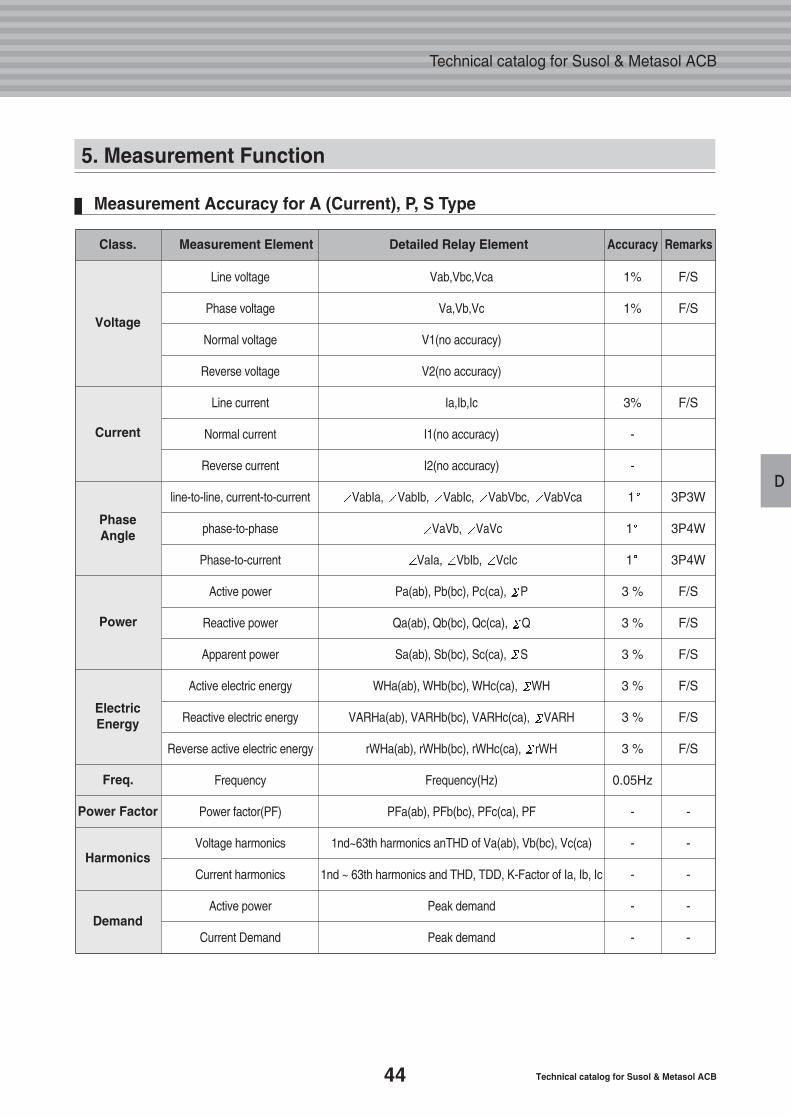
5. Measurement Function
Measurement Accuracy for A (Current), P, S Type
Voltage
Current
Phase Angle
Power
Electric Energy
Freq.
Power Factor
Harmonics
Demand
Class. Accuracy RemarksMeasurement Element Detailed Relay Element
45
D
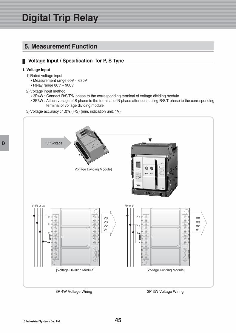
Voltage Input / Specification for P, S Type
1. Voltage Input
1) Rated voltage inputMeasurement range 60V ~ 690VRelay range 80V ~ 900V
2) Voltage input method 3P4W : Connect R/S/T/N phase to the corresponding terminal of voltage dividing module3P3W : Attach voltage of S phase to the terminal of N phase after connecting R/S/T phase to the corresponding
terminal of voltage dividing module
3) Voltage accuracy : 1.0% (F/S) (min. indication unit: 1V)
3P 4W Voltage Wiring 3P 3W Voltage Wiring
[Voltage Dividing Module]
V0V3V2V1
V0V3V2V1
Vr Vs Vt Vn Vr Vs Vt
3P voltage
[Voltage Dividing Module] [Voltage Dividing Module]
Digital Trip Relay
5. Measurement Function
46 Technical catalog for Susol & Metasol ACB
Technical catalog for Susol & Metasol ACB
D
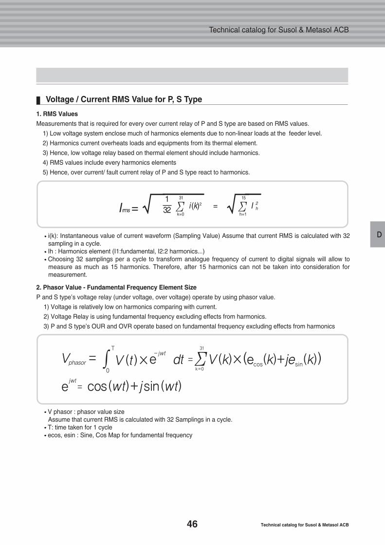
Voltage / Current RMS Value for P, S Type
i(k): Instantaneous value of current waveform (Sampling Value) Assume that current RMS is calculated with 32sampling in a cycle. Ih : Harmonics element (I1:fundamental, I2:2 harmonics...)Choosing 32 samplings per a cycle to transform analogue frequency of current to digital signals will allow tomeasure as much as 15 harmonics. Therefore, after 15 harmonics can not be taken into consideration formeasurement.
V phasor : phasor value sizeAssume that current RMS is calculated with 32 Samplings in a cycle.T: time taken for 1 cycleecos, esin : Sine, Cos Map for fundamental frequency
Irms = √132 i (k)2 I 2
h=Σ31
k=0√Σ
15
h=1
1. RMS Values
Measurements that is required for every over current relay of P and S type are based on RMS values.
1) Low voltage system enclose much of harmonics elements due to non-linear loads at the feeder level.
2) Harmonics current overheats loads and equipments from its thermal element.
3) Hence, low voltage relay based on thermal element should include harmonics.
4) RMS values include every harmonics elements
5) Hence, over current/ fault current relay of P and S type react to harmonics.
2. Phasor Value - Fundamental Frequency Element Size
P and S type’s voltage relay (under voltage, over voltage) operate by using phasor value.
1) Voltage is relatively low on harmonics comparing with current.
2) Voltage Relay is using fundamental frequency excluding effects from harmonics.
3) P and S type’s OUR and OVR operate based on fundamental frequency excluding effects from harmonics
jwt=e cos(wt)+jsin(wt)
Vphasor =∫T
-jwt
0
=V (t)×e dt V(k)×(e (k)+je (k))Σ31
k=0cos sin
47
D
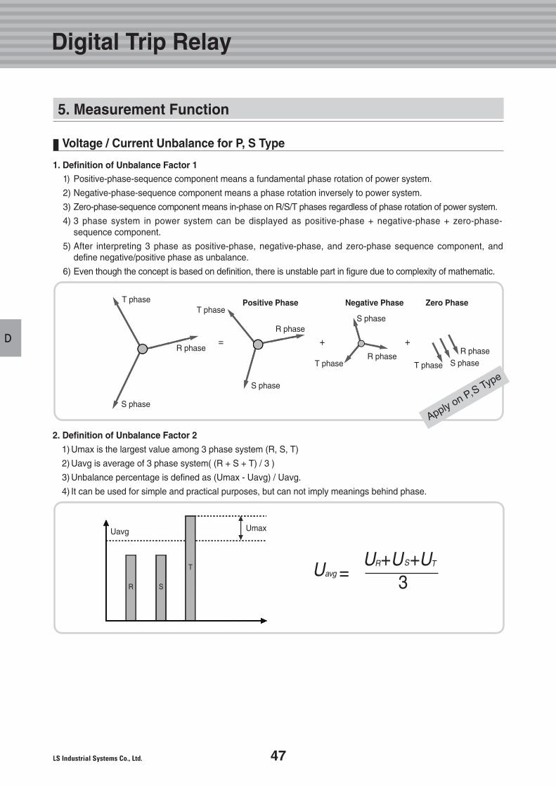
Voltage / Current Unbalance for P, S Type
U = 3avg
U + +R US UT
1. Definition of Unbalance Factor 1
2. Definition of Unbalance Factor 2
1) Umax is the largest value among 3 phase system (R, S, T)
2) Uavg is average of 3 phase system( (R + S + T) / 3 )
3) Unbalance percentage is defined as (Umax - Uavg) / Uavg.
4) It can be used for simple and practical purposes, but can not imply meanings behind phase.
T phase Positive Phase Negative Phase Zero PhaseT phase
= + +
T phase T phase
R phase
Uavg
R S
T
Umax
R phase
R phaseR phase
S phase
S phase
S phase
S phase
Digital Trip Relay
5. Measurement Function
1) Positive-phase-sequence component means a fundamental phase rotation of power system.
2) Negative-phase-sequence component means a phase rotation inversely to power system.
3) Zero-phase-sequence component means in-phase on R/S/T phases regardless of phase rotation of power system.
4) 3 phase system in power system can be displayed as positive-phase + negative-phase + zero-phase-sequence component.
5) After interpreting 3 phase as positive-phase, negative-phase, and zero-phase sequence component, anddefine negative/positive phase as unbalance.
6) Even though the concept is based on definition, there is unstable part in figure due to complexity of mathematic.
Apply on P,S Type
48 Technical catalog for Susol & Metasol ACB
Technical catalog for Susol & Metasol ACB
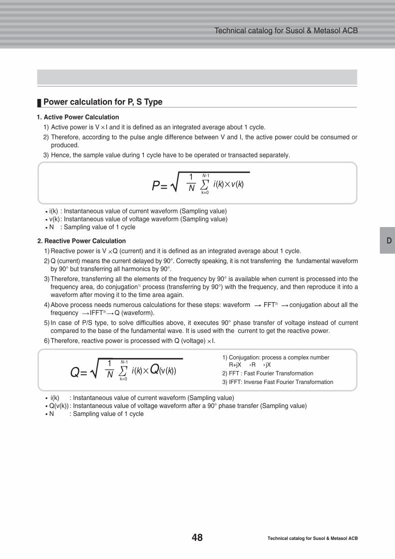
D2. Reactive Power Calculation
1) Reactive power is V Q (current) and it is defined as an integrated average about 1 cycle.
2) Q (current) means the current delayed by 90°. Correctly speaking, it is not transferring the fundamental waveformby 90° but transferring all harmonics by 90°.
3) Therefore, transferring all the elements of the frequency by 90° is available when current is processed into the frequency area, do conjugation1) process (transferring by 90°) with the frequency, and then reproduce it into a waveform after moving it to the time area again.
4) Above process needs numerous calculations for these steps: waveform FFT2) conjugation about all the frequency IFFT3) Q (waveform).
5) In case of P/S type, to solve difficulties above, it executes 90° phase transfer of voltage instead of current compared to the base of the fundamental wave. It is used with the current to get the reactive power.
6) Therefore, reactive power is processed with Q (voltage) I.
Power calculation for P, S Type
i(k) : Instantaneous value of current waveform (Sampling value)v(k): Instantaneous value of voltage waveform (Sampling value)N : Sampling value of 1 cycle
i(k) : Instantaneous value of current waveform (Sampling value)Q(v(k)) : Instantaneous value of voltage waveform after a 90° phase transfer (Sampling value)N : Sampling value of 1 cycle
1) Conjugation: process a complex number R+jX R jX
2) FFT : Fast Fourier Transformation3) IFFT: Inverse Fast Fourier Transformation
P=√1N i (k)×v (k)Σ
N-1
k=0
Q=√1N i (k)×Q(v(k))Σ
N-1
k=0
1. Active Power Calculation
1) Active power is V I and it is defined as an integrated average about 1 cycle.
2) Therefore, according to the pulse angle difference between V and I, the active power could be consumed or produced.
3) Hence, the sample value during 1 cycle have to be operated or transacted separately.
49
D
: Power Production: Power Consumption
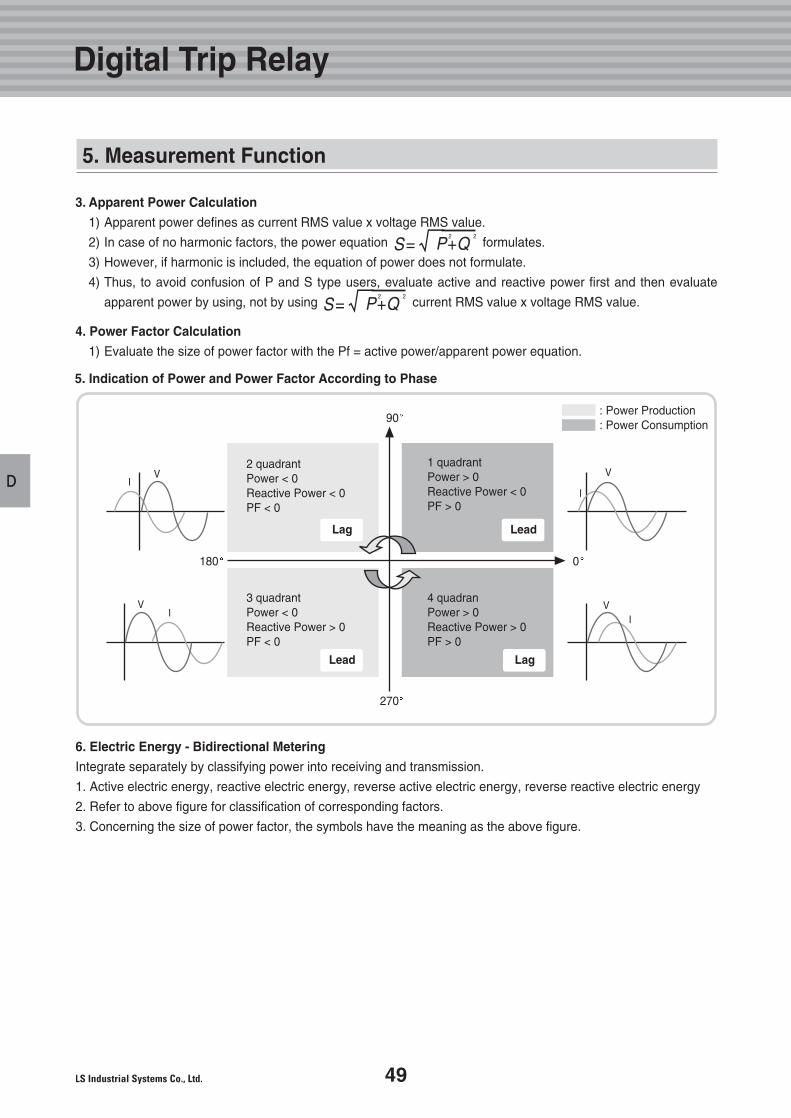
3. Apparent Power Calculation
1) Apparent power defines as current RMS value x voltage RMS value.
2) In case of no harmonic factors, the power equation formulates.
3) However, if harmonic is included, the equation of power does not formulate.
4) Thus, to avoid confusion of P and S type users, evaluate active and reactive power first and then evaluate
apparent power by using, not by using current RMS value x voltage RMS value.
4. Power Factor Calculation
1) Evaluate the size of power factor with the Pf = active power/apparent power equation.
5. Indication of Power and Power Factor According to Phase
6. Electric Energy - Bidirectional Metering
Integrate separately by classifying power into receiving and transmission.
1. Active electric energy, reactive electric energy, reverse active electric energy, reverse reactive electric energy
2. Refer to above figure for classification of corresponding factors.
3. Concerning the size of power factor, the symbols have the meaning as the above figure.
IV
I
V
IV
IV
1 quadrantPower > 0 Reactive Power < 0 PF > 0
90
0180
270
4 quadranPower > 0 Reactive Power > 0PF > 0
3 quadrantPower < 0 Reactive Power > 0 PF < 0
2 quadrantPower < 0 Reactive Power < 0PF < 0
S=√P+Q2 2
S=√P+Q2 2
Digital Trip Relay
5. Measurement Function
Lag Lead
LagLead
50 Technical catalog for Susol & Metasol ACB
Technical catalog for Susol & Metasol ACB
D
Demand / Peak Demand for P, S Type
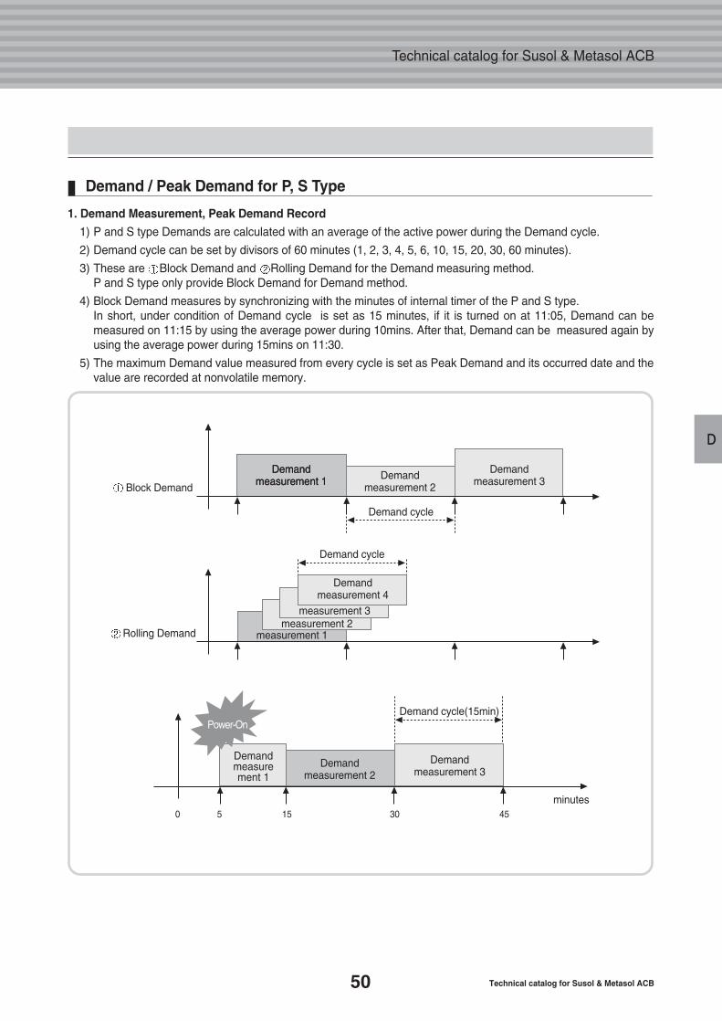
1. Demand Measurement, Peak Demand Record
1) P and S type Demands are calculated with an average of the active power during the Demand cycle.
2) Demand cycle can be set by divisors of 60 minutes (1, 2, 3, 4, 5, 6, 10, 15, 20, 30, 60 minutes).
3) These are Block Demand and Rolling Demand for the Demand measuring method. P and S type only provide Block Demand for Demand method.
4) Block Demand measures by synchronizing with the minutes of internal timer of the P and S type. In short, under condition of Demand cycle is set as 15 minutes, if it is turned on at 11:05, Demand can be measured on 11:15 by using the average power during 10mins. After that, Demand can be measured again by using the average power during 15mins on 11:30.
5) The maximum Demand value measured from every cycle is set as Peak Demand and its occurred date and the value are recorded at nonvolatile memory.
Demand cycle
Block Demand
Demand measurement 1
Demand measurement 1
Demand measurement 4
measurement 3measurement 2
measurement 1
Demand measurement 3Demand
measurement 2
Demand measurement 1
Demand measurement 3
Demand measurement 2
Rolling Demand
0 5
Power-On
15 30 45
Demand cycle
Demand cycle(15min)
minutes
51
D
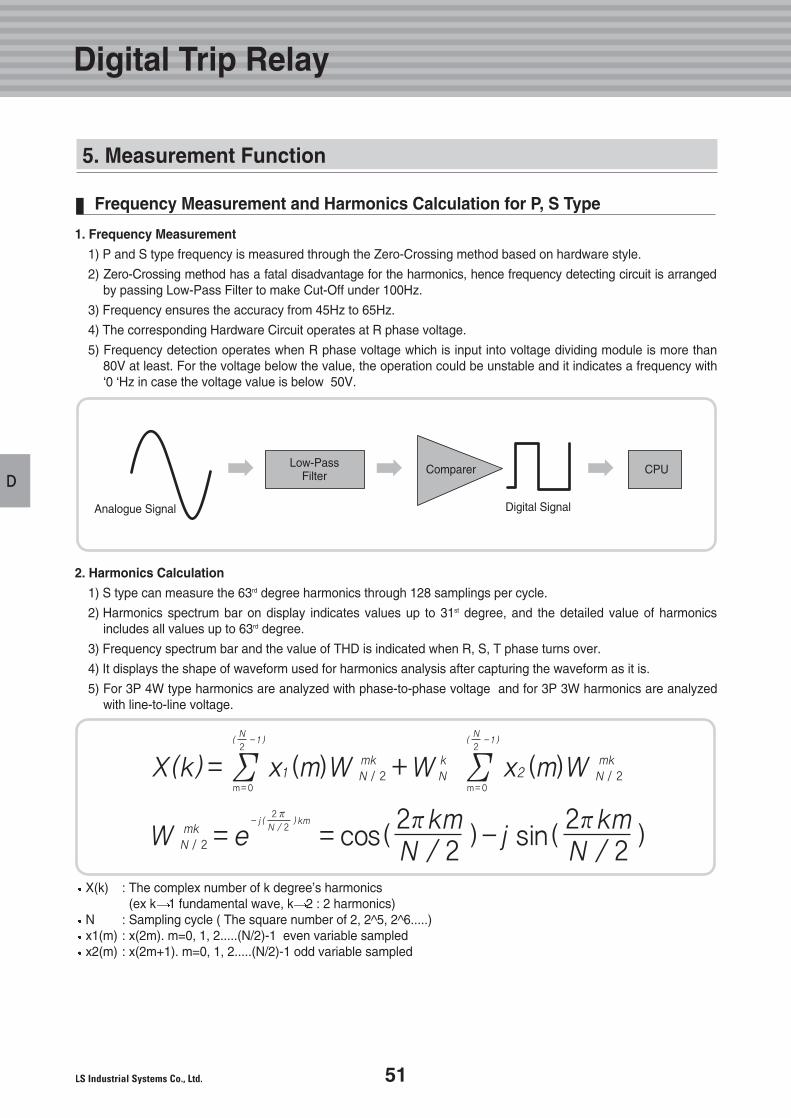
Frequency Measurement and Harmonics Calculation for P, S Type
X(k) : The complex number of k degree’s harmonics(ex k 1 fundamental wave, k 2 : 2 harmonics)
N : Sampling cycle ( The square number of 2, 2^5, 2^6.....)x1(m) : x(2m). m=0, 1, 2.....(N/2)-1 even variable sampledx2(m) : x(2m+1). m=0, 1, 2.....(N/2)-1 odd variable sampled
1. Frequency Measurement
1) P and S type frequency is measured through the Zero-Crossing method based on hardware style.
2) Zero-Crossing method has a fatal disadvantage for the harmonics, hence frequency detecting circuit is arrangedby passing Low-Pass Filter to make Cut-Off under 100Hz.
3) Frequency ensures the accuracy from 45Hz to 65Hz.
4) The corresponding Hardware Circuit operates at R phase voltage.
5) Frequency detection operates when R phase voltage which is input into voltage dividing module is more than 80V at least. For the voltage below the value, the operation could be unstable and it indicates a frequency with‘0 ‘Hz in case the voltage value is below 50V.
2. Harmonics Calculation
1) S type can measure the 63rd degree harmonics through 128 samplings per cycle.
2) Harmonics spectrum bar on display indicates values up to 31st degree, and the detailed value of harmonics includes all values up to 63rd degree.
3) Frequency spectrum bar and the value of THD is indicated when R, S, T phase turns over.
4) It displays the shape of waveform used for harmonics analysis after capturing the waveform as it is.
5) For 3P 4W type harmonics are analyzed with phase-to-phase voltage and for 3P 3W harmonics are analyzed with line-to-line voltage.
X(k) = x1 (m)W N / 2 +W N x2 (m)W N / 2ΣN
2-1( )
m=0Σ
N
2-1( )
m=0
mk mkk
W N / 2 = e = cos( )-j sin( )2 πN / 2
km- j ( ) 2πkmN / 2
2πkmN / 2
mk
Low-PassFilter
Analogue Signal Digital Signal
CPUComparer
Digital Trip Relay
5. Measurement Function
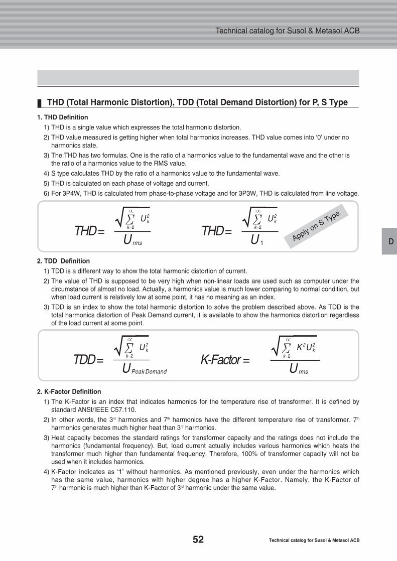
52 Technical catalog for Susol & Metasol ACB
Technical catalog for Susol & Metasol ACB
D
THD (Total Harmonic Distortion), TDD (Total Demand Distortion) for P, S Type
THD= U
U 2k√Σ∝
k=2
rms
TDD= U
U 2k√Σ∝
k=2
Peak Demand
K-Factor = U
K 2U 2k√Σ∝
k=2
rms
THD= U
U 2k√Σ∝
k=2
1
1. THD Definition
1) THD is a single value which expresses the total harmonic distortion.
2) THD value measured is getting higher when total harmonics increases. THD value comes into ‘0’ under no harmonics state.
3) The THD has two formulas. One is the ratio of a harmonics value to the fundamental wave and the other is the ratio of a harmonics value to the RMS value.
4) S type calculates THD by the ratio of a harmonics value to the fundamental wave.
5) THD is calculated on each phase of voltage and current.
6) For 3P4W, THD is calculated from phase-to-phase voltage and for 3P3W, THD is calculated from line voltage.
2. TDD Definition
1) TDD is a different way to show the total harmonic distortion of current.
2) The value of THD is supposed to be very high when non-linear loads are used such as computer under the circumstance of almost no load. Actually, a harmonics value is much lower comparing to normal condition, but when load current is relatively low at some point, it has no meaning as an index.
3) TDD is an index to show the total harmonic distortion to solve the problem described above. As TDD is the total harmonics distortion of Peak Demand current, it is available to show the harmonics distortion regardless of the load current at some point.
2. K-Factor Definition
1) The K-Factor is an index that indicates harmonics for the temperature rise of transformer. It is defined by standard ANSI/IEEE C57.110.
2) In other words, the 3rd harmonics and 7th harmonics have the different temperature rise of transformer. 7th
harmonics generates much higher heat than 3rd harmonics.
3) Heat capacity becomes the standard ratings for transformer capacity and the ratings does not include the harmonics (fundamental frequency). But, load current actually includes various harmonics which heats the transformer much higher than fundamental frequency. Therefore, 100% of transformer capacity will not be used when it includes harmonics.
4) K-Factor indicates as ‘1’ without harmonics. As mentioned previously, even under the harmonics which has the same value, harmonics with higher degree has a higher K-Factor. Namely, the K-Factor of 7th harmonic is much higher than K-Factor of 3rd harmonic under the same value.
Apply on S Type
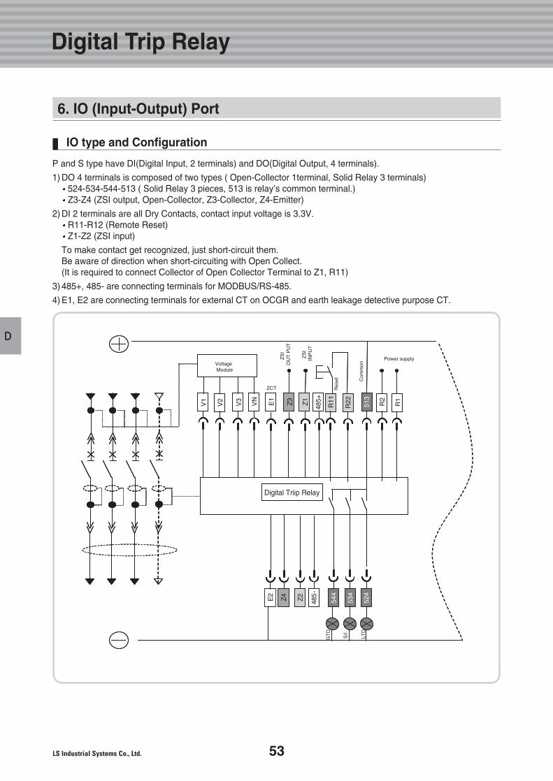
53
D
6. IO (Input-Output) Port
IO type and Configuration
P and S type have DI(Digital Input, 2 terminals) and DO(Digital Output, 4 terminals).
1) DO 4 terminals is composed of two types ( Open-Collector 1terminal, Solid Relay 3 terminals)524-534-544-513 ( Solid Relay 3 pieces, 513 is relay’s common terminal.)Z3-Z4 (ZSI output, Open-Collector, Z3-Collector, Z4-Emitter)
2) DI 2 terminals are all Dry Contacts, contact input voltage is 3.3V.R11-R12 (Remote Reset)Z1-Z2 (ZSI input)
To make contact get recognized, just short-circuit them.Be aware of direction when short-circuiting with Open Collect.(It is required to connect Collector of Open Collector Terminal to Z1, R11)
3) 485+, 485- are connecting terminals for MODBUS/RS-485.
4) E1, E2 are connecting terminals for external CT on OCGR and earth leakage detective purpose CT.
Digital Triip Relay
Digital Trip Relay
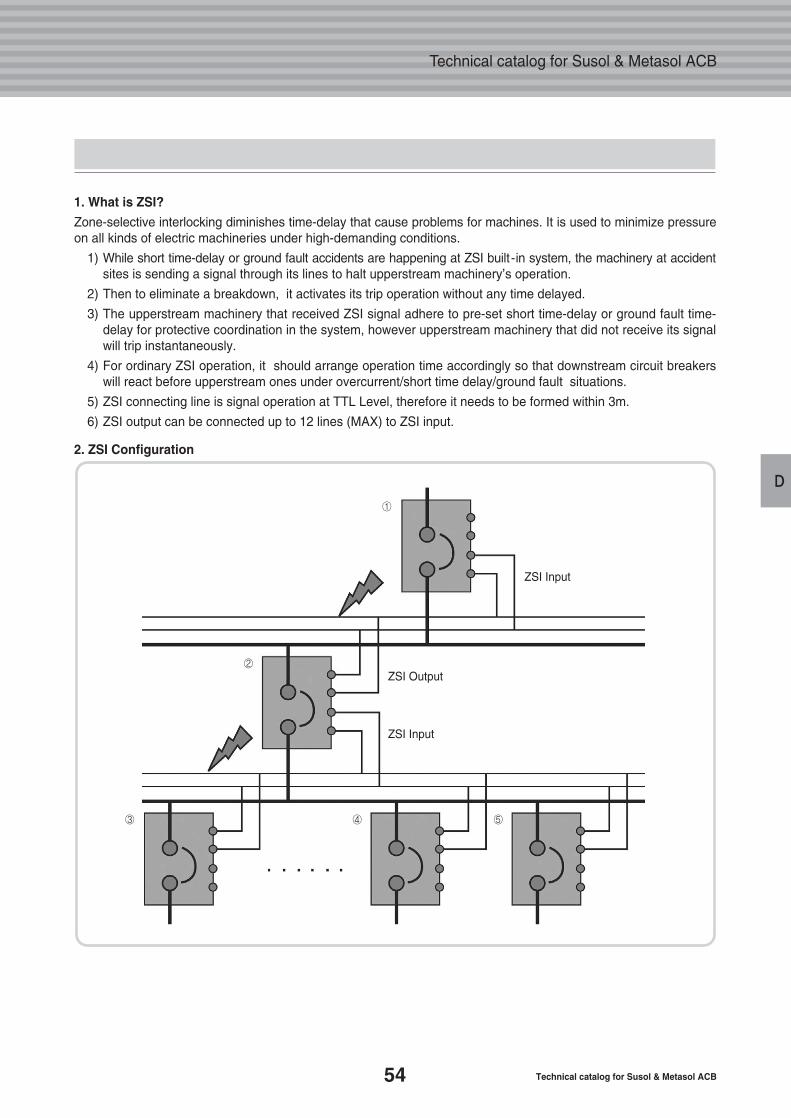
54 Technical catalog for Susol & Metasol ACB
Technical catalog for Susol & Metasol ACB
D
1. What is ZSI?
Zone-selective interlocking diminishes time-delay that cause problems for machines. It is used to minimize pressureon all kinds of electric machineries under high-demanding conditions.
1) While short time-delay or ground fault accidents are happening at ZSI built -in system, the machinery at accidentsites is sending a signal through its lines to halt upperstream machinery’s operation.
2) Then to eliminate a breakdown, it activates its trip operation without any time delayed.
3) The upperstream machinery that received ZSI signal adhere to pre-set short time-delay or ground fault time-delay for protective coordination in the system, however upperstream machinery that did not receive its signalwill trip instantaneously.
4) For ordinary ZSI operation, it should arrange operation time accordingly so that downstream circuit breakers will react before upperstream ones under overcurrent/short time delay/ground fault situations.
5) ZSI connecting line is signal operation at TTL Level, therefore it needs to be formed within 3m.
6) ZSI output can be connected up to 12 lines (MAX) to ZSI input.
2. ZSI Configuration
①
ZSI Input
ZSI Output
ZSI Input
②
③ ④ ⑤
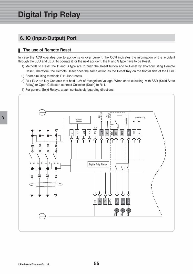
55
D
The use of Remote Reset
In case the ACB operates due to accidents or over current, the OCR indicates the information of the accidentthrough the LCD and LED. To operate it for the next accident, the P and S type have to be Reset.
1) Methods to Reset the P and S type are to push the Reset button and to Reset by short-circuiting Remote
Reset. Therefore, the Remote Reset does the same action as the Reset Key on the frontal side of the OCR.
2) Short-circuiting terminals R11-R22 resets.
3) R11-R22 are Dry Contacts that hold 3.3V of recognition voltage. When short-circuiting with SSR (Solid State Relay) or Open-Collector, connect Collector (Drain) to R11.
4) For general Solid Relays, attach contacts disregarding directions.
Digital Triip Relay
Digital Trip Relay
6. IO (Input-Output) Port
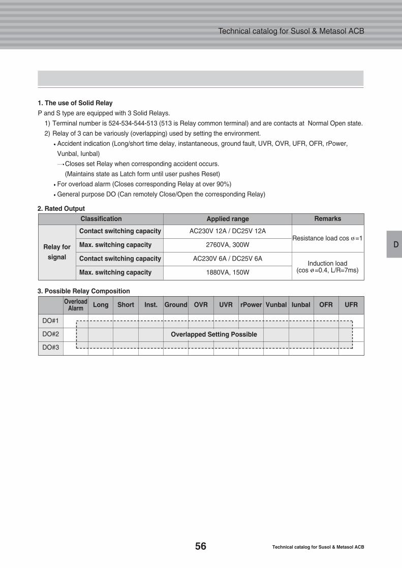
56 Technical catalog for Susol & Metasol ACB
Technical catalog for Susol & Metasol ACB
D
Overlapped Setting Possible
Relay for
signal
Classification
Contact switching capacity
Max. switching capacity
Contact switching capacity
Max. switching capacity
RemarksApplied range
Resistance load cos =1
Induction load (cos =0.4, L/R=7ms)
AC230V 12A / DC25V 12A
2760VA, 300W
AC230V 6A / DC25V 6A
1880VA, 150W
DO#1
DO#2
DO#3
UFROFRIunbalVunbalrPowerUVROVRGroundInst.ShortLongOverloadAlarm
1. The use of Solid Relay
P and S type are equipped with 3 Solid Relays.
1) Terminal number is 524-534-544-513 (513 is Relay common terminal) and are contacts at Normal Open state.
2) Relay of 3 can be variously (overlapping) used by setting the environment.
Accident indication (Long/short time delay, instantaneous, ground fault, UVR, OVR, UFR, OFR, rPower,
Vunbal, Iunbal)
Closes set Relay when corresponding accident occurs.
(Maintains state as Latch form until user pushes Reset)
For overload alarm (Closes corresponding Relay at over 90%)
General purpose DO (Can remotely Close/Open the corresponding Relay)
2. Rated Output
3. Possible Relay Composition
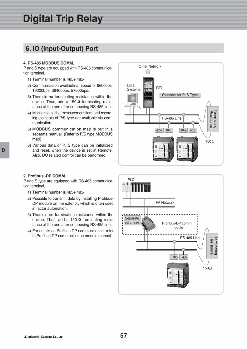
57
D
4. RS-485 MODBUS COMM.P and S type are equipped with RS-485 communica-tion terminal.
1) Terminal number is 485+ 485-.
2) Communication available at speed of 9600bps,19200bps, 38400bps, 57600bps.
3) There is no terminating resistance within the device. Thus, add a 150 terminating resis-tance at the end after composing RS-485 line.
4) Monitoring all the measurement item and record-ing elements of P/S type are available via com-munication.
5) MODBUS communication map is put in a separate manual. (Refer to P/S type MODBUSmap)
6) Various data of P, S type can be initialized and reset, when the device is set at Remote. Also, DO related control can be performed.
2. Profibus -DP COMM.P and S type are equipped with RS-485 communica-tion terminal.
1) Terminal number is 485+ 485-.
2) Possible to transmit data by installing Profibus-DP module on the exterior, which is often usedin factor automation.
3) There is no terminating resistance within the device. Thus, add a 150 terminating resis-tance at the end after composing RS-485 line.
4) For details on Profibus-DP communication, referto Profibus-DP communication module manual.
Other Network
Local Systems RTU
Standard for P, S Type
Profibus-DP comm.module
PLC
FA Network
Separate purchase
RS-485 Line
RS-485 Line
485+ 485-
150Ω
485+ 485- 485+ 485-
150Ω
Terminating
Resistance
Terminating
Resistance
Digital Trip Relay
6. IO (Input-Output) Port
E.Digital TripRelay Accessory
59
63
65
66
67
1. TRIO Unit
2. Profibus-DPCommunication
3. MODBUS
4. Temperature
5. OCR Tester
58 Technical catalog for Susol & Metasol ACB
Technical catalog for Susol & Metasol ACB
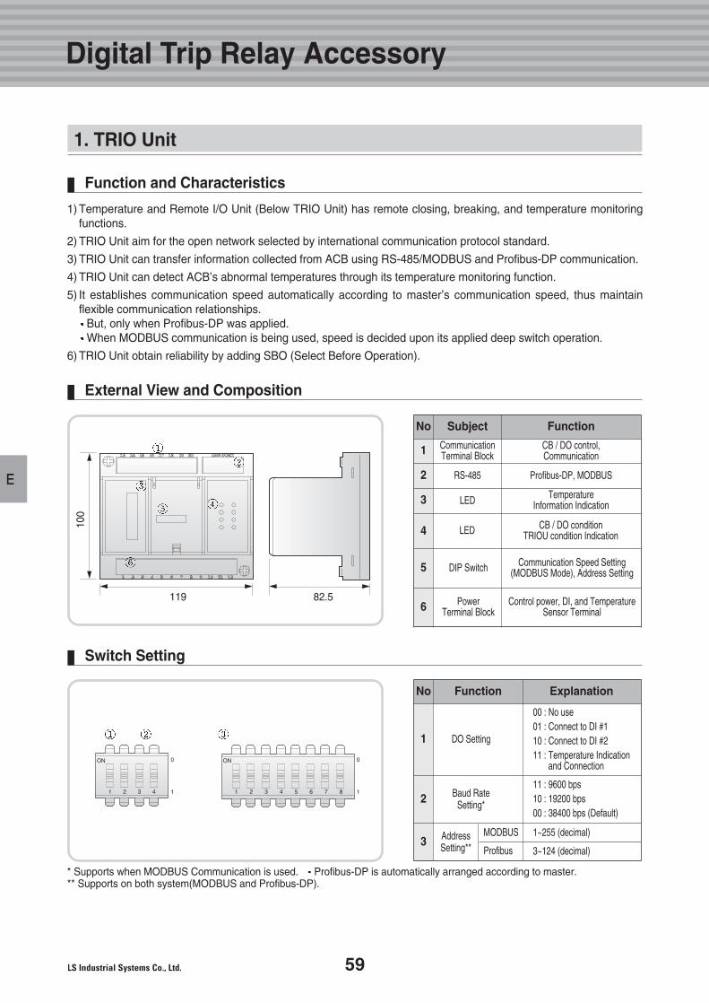
59
E
1. TRIO Unit
Function and Characteristics
External View and Composition
Switch Setting
1) Temperature and Remote I/O Unit (Below TRIO Unit) has remote closing, breaking, and temperature monitoring functions.
2) TRIO Unit aim for the open network selected by international communication protocol standard.
3) TRIO Unit can transfer information collected from ACB using RS-485/MODBUS and Profibus-DP communication.
4) TRIO Unit can detect ACB’s abnormal temperatures through its temperature monitoring function.
5) It establishes communication speed automatically according to master’s communication speed, thus maintain flexible communication relationships.
But, only when Profibus-DP was applied.When MODBUS communication is being used, speed is decided upon its applied deep switch operation.
6) TRIO Unit obtain reliability by adding SBO (Select Before Operation).
* Supports when MODBUS Communication is used. Profibus-DP is automatically arranged according to master.** Supports on both system(MODBUS and Profibus-DP).
Subject
CommunicationTerminal Block
CB / DO control,Communication
CB / DO conditionTRIOU condition Indication
Communication Speed Setting(MODBUS Mode), Address Setting
Control power, DI, and TemperatureSensor Terminal
TemperatureInformation Indication
PowerTerminal Block
RS-485 Profibus-DP, MODBUS
LED
LED
DIP Switch
1
2
3
4
5
6
Function
FunctionNo
No
DO Setting
AddressSetting**
Baud RateSetting*
00 : No use01 : Connect to DI #110 : Connect to DI #211 : Temperature Indication
and Connection
11 : 9600 bps10 : 19200 bps00 : 38400 bps (Default)
1~255 (decimal)MODBUS
Profibus 3~124 (decimal)
1
2
3
Explanation
1 2 3 4
0
1
0
1
ON ON
1 2 3 4 5 6 7 8
100
119 82.5
Digital Trip Relay Accessory
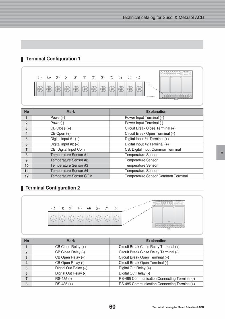
60 Technical catalog for Susol & Metasol ACB
Technical catalog for Susol & Metasol ACB
E
Terminal Configuration 1
123456789101112
No Mark Explanation
Power(+)Power(-)CB Close (+)CB Open (+)Digital input #1 (+)Digital input #2 (+)CB, Digital Input ComTemperature Sensor #1Temperature Sensor #2Temperature Sensor #3Temperature Sensor #4Temperature Sensor COM
Power Input Terminal (+)Power Input Terminal (-)Circuit Break Close Terminal (+)Circuit Break Open Terminal (+)Digital Input #1 Terminal (+)Digital Input #2 Terminal (+)CB, Digital Input Common TerminalTemperature SensorTemperature SensorTemperature SensorTemperature SensorTemperature Sensor Common Terminal
Terminal Configuration 2
12345678
No Mark Explanation
CB Close Relay (+)CB Close Relay (-)CB Open Relay (+)CB Open Relay (-)Digital Out Relay (+)Digital Out Relay (-)RS-485 (-)RS-485 (+)
Circuit Break Close Relay Terminal (+)Circuit Break Close Relay Terminal (-)Circuit Break Open Terminal (+)Circuit Break Open Terminal (-)Digital Out Relay (+)Digital Out Relay (-)RS-485 Communication Connecting Terminal (-)RS-485 Communication Connecting Terminal(+)
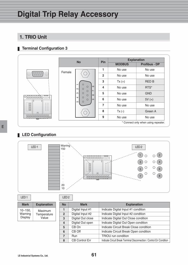
61
E
ExplanationMark
10~150,WarningDisplay
LED 1
Terminal Configuration 3
LED Configuration
12345678
No Mark Explanation
Digital Input #1Digital Input #2Digital Out closeDigital Out openCB OnCB OffRun CB Control Err
Indicate Digital Input #1 conditionIndicate Digital Input #2 conditionIndicate Digital Out Close conditionIndicate Digital Out Open conditionIndicate Circuit Break Close conditionIndicate Circuit Break Open conditionTRIOU run conditionIndicate Circuit Break Terminal Disconnection / Control Err Condition
LED 2
MaximumTemperature
Value
LED 2LED 1 Warring150
.
.
.
.
.
.
.
.
.
.2010
1
3
5
7
2
4
6
8
1
2
3
4
5
6
7
8
9
No Pin
Female
Profibus - DPMODBUSExplanation
No use
No use
Tx (+)
No use
No use
No use
No use
Tx (-)
No use
No use
No use
RED B
RTS*
GND
5V (+)
No use
Green A
No use
* Connect only when using repeater.
54
32
1
98
76
Digital Trip Relay Accessory
1. TRIO Unit
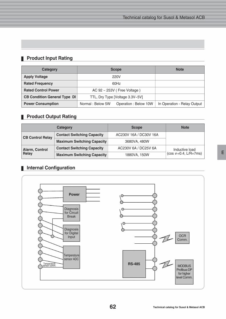
62 Technical catalog for Susol & Metasol ACB
Technical catalog for Susol & Metasol ACB
E
Product Input Rating
Apply Voltage
Rated Frequency
Rated Control Power
CB Condition General Type DI
Power Consumption
Category Scope Note
220V
60Hz
AC 92 ~ 253V ( Free Voltage )
TTL, Dry Type [Voltage 3.3V~5V]
Normal : Below 5W Operation : Below 10W In Operation - Relay Output
Product Output Rating
Internal Configuration
CB Control Relay
Alarm, Control Relay
Category Scope Note
Contact Switching Capacity
Maximum Switching Capacity
Contact Switching Capacity
Maximum Switching Capacity
AC230V 16A / DC30V 16A
3680VA, 480W
AC230V 6A / DC25V 6A
1880VA, 150WInductive load
(cos =0.4, L/R=7ms)
Temperature sensor comm.
Diagnosis for Circuit
Break
Diagnosisfor Digital
Input
Temperaturesensor ADC
OCRComm.
MODBUSProfibus-DP for higher
level Comm.
RS-485
Power
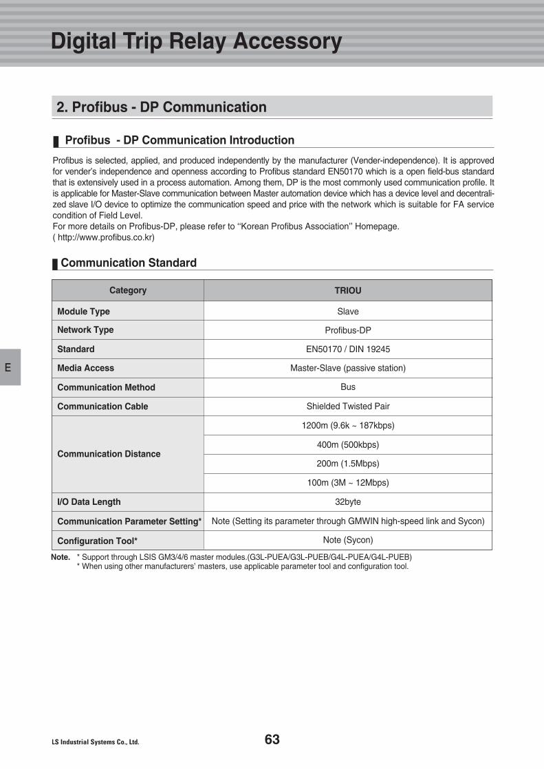
63
E
Communication Standard
Module Type
Network Type
Standard
Media Access
Communication Method
Communication Cable
Communication Distance
I/O Data Length
Communication Parameter Setting*
Configuration Tool*
Category TRIOU
Slave
Profibus-DP
EN50170 / DIN 19245
Master-Slave (passive station)
Bus
Shielded Twisted Pair
1200m (9.6k ~ 187kbps)
400m (500kbps)
200m (1.5Mbps)
100m (3M ~ 12Mbps)
32byte
Note (Setting its parameter through GMWIN high-speed link and Sycon)
Note (Sycon)
Profibus is selected, applied, and produced independently by the manufacturer (Vender-independence). It is approvedfor vender’s independence and openness according to Profibus standard EN50170 which is a open field-bus standardthat is extensively used in a process automation. Among them, DP is the most commonly used communication profile. Itis applicable for Master-Slave communication between Master automation device which has a device level and decentrali-zed slave I/O device to optimize the communication speed and price with the network which is suitable for FA servicecondition of Field Level. For more details on Profibus-DP, please refer to ‘‘Korean Profibus Association’’ Homepage.( http://www.profibus.co.kr)
Profibus - DP Communication Introduction
Note. * Support through LSIS GM3/4/6 master modules.(G3L-PUEA/G3L-PUEB/G4L-PUEA/G4L-PUEB)* When using other manufacturers’ masters, use applicable parameter tool and configuration tool.
Digital Trip Relay Accessory
2. Profibus - DP Communication
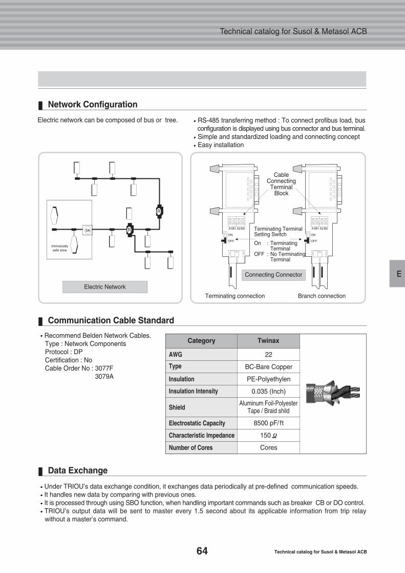
64 Technical catalog for Susol & Metasol ACB
Technical catalog for Susol & Metasol ACB
E
AWG
Type
Insulation
Insulation Intensity
Electrostatic Capacity
Characteristic Impedance
Number of Cores
Category Twinax
Under TRIOU’s data exchange condition, it exchanges data periodically at pre-defined communication speeds. It handles new data by comparing with previous ones. It is processed through using SBO function, when handling important commands such as breaker CB or DO control. TRIOU’s output data will be sent to master every 1.5 second about its applicable information from trip relaywithout a master’s command.
RS-485 transferring method : To connect profibus load, busconfiguration is displayed using bus connector and bus terminal. Simple and standardized loading and connecting conceptEasy installation
Data Exchange
Recommend Belden Network Cables.Type : Network ComponentsProtocol : DPCertification : NoCable Order No : 3077F
3079A
Communication Cable Standard
Electric network can be composed of bus or tree.
Electric Network
Terminating connection Branch connection
CableConnecting
TerminalBlock
Terminating Terminal Setting Switch
On : Terminating Terminal
OFF : No Terminating Terminal
Network Configuration
22
BC-Bare Copper
PE-Polyethylen
0.035 (Inch)
8500 pF/ ft
150
Cores
ShieldAluminum Foil-Polyester
Tape / Braid shild
Connecting Connector
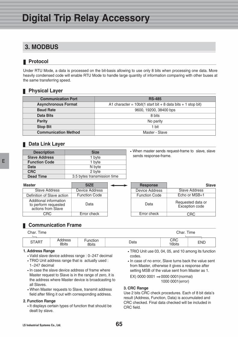
65
E
3. MODBUS
Communication Frame
ENDCRC16bitsSTART
Char. Time
Address8bits
Function8bits
Data
1. Address RangeValid slave device address range : 0~247 decimalTRIO Unit address range that is actually used : 1~247 decimalIn case the slave device address of frame where Master request to Slave is in the range of zero, it is the address where Master device is broadcasting to all Slaves.When Master requests to Slave, transmit address field after filling it out with corresponding address.
2. Function RangeIt displays certain types of function that should be dealt by slave.
TRIO Unit use 03, 04, 05, and 10 among its functioncodes. In case of no error, Slave turns back the value sent from Master, otherwise it gives a response after setting MSB of the value sent from Master as 1.
EX) 0000 0001 0000 0001(normal)1000 0001(error)
3. CRC RangeUse 2 bits CRC check procedures. Each of 8 bit data’sresult (Address, Function, Data) is accumulated andCRC checked. Final data checked will be included inCRC field.
Under RTU Mode, a data is processed on the bit-basis allowing to use only 8 bits when processing one data. Moreheavily condensed code will enable RTU Mode to handle large quantity of information comparing with other buses atthe same transferring speed.
When master sends request-frame to slave, slavesends response-frame.
Protocol
Physical Layer
Asynchronous FormatBaud RateData BitsParityStop BitCommunication Method
Communication Port RS-485A1 character = 10bit(1 start bit + 8 data bits + 1 stop bit)
9600, 19200, 38400 bps 8 bits
No parity1 bit
Master - Slave
Data Link Layer
Slave AddressFunction CodeDataCRCDead Time
Description Size1 byte1 byteN byte2 byte
3.5 bytes transmission time
Slave AddressDefinition of Slave action
Additional informationto perform requestedactions from Slave
CRC
SIZEMasterDevice AddressFunction Code
Data
Error check
Char. Time
Slave AddressEcho or MSB=1
Requested data or Exception code
CRC
Response SlaveDevice AddressFunction Code
Data
Error check
Digital Trip Relay Accessory
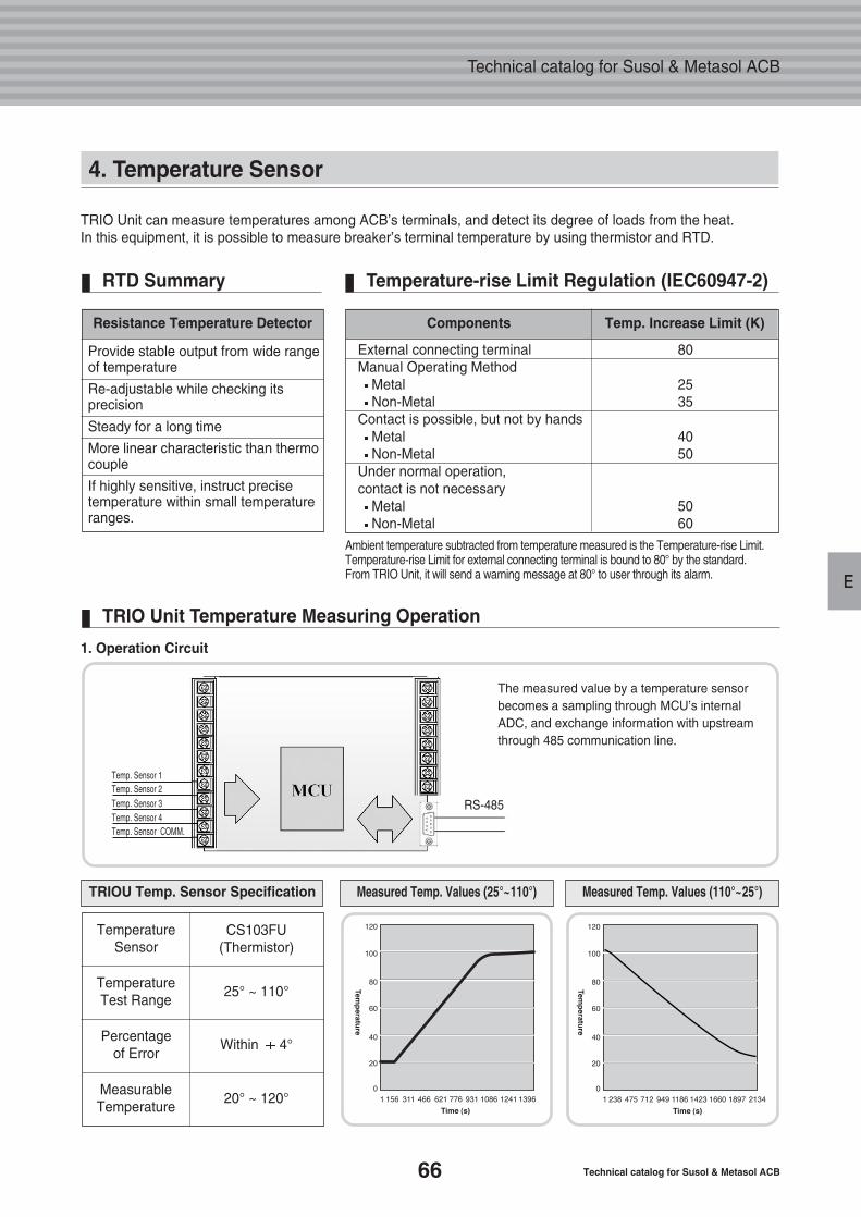
66 Technical catalog for Susol & Metasol ACB
Technical catalog for Susol & Metasol ACB
E
4. Temperature Sensor
Resistance Temperature Detector
Provide stable output from wide rangeof temperature
Re-adjustable while checking itsprecision
Steady for a long time
More linear characteristic than thermocouple
If highly sensitive, instruct precisetemperature within small temperatureranges.
TRIO Unit can measure temperatures among ACB’s terminals, and detect its degree of loads from the heat. In this equipment, it is possible to measure breaker’s terminal temperature by using thermistor and RTD.
Ambient temperature subtracted from temperature measured is the Temperature-rise Limit.Temperature-rise Limit for external connecting terminal is bound to 80° by the standard.From TRIO Unit, it will send a warning message at 80° to user through its alarm.
RTD Summary Temperature-rise Limit Regulation (IEC60947-2)
TRIO Unit Temperature Measuring Operation
Components Temp. Increase Limit (K)
External connecting terminal Manual Operating Method
MetalNon-Metal
Contact is possible, but not by handsMetalNon-Metal
Under normal operation, contact is not necessary
MetalNon-Metal
80
2535
4050
5060
CS103FU(Thermistor)
Temperature Sensor
TemperatureTest Range
Percentage of Error
MeasurableTemperature
25° ~ 110°
Within 4°
20° ~ 120°
RS-485
The measured value by a temperature sensorbecomes a sampling through MCU’s internalADC, and exchange information with upstreamthrough 485 communication line.
TRIOU Temp. Sensor Specification Measured Temp. Values (110°~25°)Measured Temp. Values (25°~110°)
1. Operation Circuit
Temp. Sensor 1Temp. Sensor 2Temp. Sensor 3Temp. Sensor 4Temp. Sensor COMM.
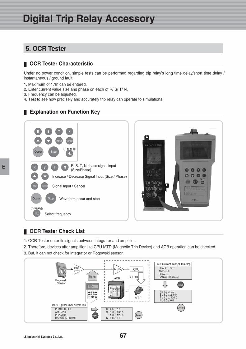
67
E
5. OCR Tester
Under no power condition, simple tests can be performed regarding trip relay’s long time delay/short time delay /instantaneous / ground fault.
1. Maximum of 17In can be entered.2. Enter current value size and phase on each of R/ S/ T/ N.3. Frequency can be adjusted.4. Test to see how precisely and accurately trip relay can operate to simulations.
OCR Tester Characteristic
1. OCR Tester enter its signals between integrator and amplifier.
2. Therefore, devices after amplifier like CPU MTD (Magnetic Trip Device) and ACB operation can be checked.
3. But, it can not check for integrator or Rogowski sensor.
RogowskiSensor
R, S, T, N phase signal input(Size/Phase)
Increase / Decrease Signal Input (Size / Phase)
Signal Input / Cancel
Waveform occur and stop
Select frequency
OCR Tester Check List
Explanation on Function Key
200% R phase Over-current Test
Intergrator
Signal
Amplifier
Input
Input
Occur
Occur
BREAK
CPU
ACB
PHASE R SETAMP=2.0PHA=0.0RANGE-(0~360.0)
Fault Current Test(ACB’s 8In)PHASE S SETAMP=8.0PHA=0.0RANGE-(0~360.0)
R : 2.0∠ 0.0S : 1 .0∠ 240.0T : 1 .0∠ 120.0N : 0.0∠ 0.0
R : 1.0∠ 0.0S : 8.0∠ 240.0T : 1.0∠ 120.0N : 0.0∠ 0.0
Digital Trip Relay Accessory
MTD
F. Installation andService Condition
69
72
73
74
1. Safety Precaution
2. Receiving and Unpacking
3. Installation Method
4. Service Condition
68 Technical catalog for Susol & Metasol ACB
Technical catalog for Susol & Metasol ACB
69
F
Not following the instructionmay result in serious injuryand even death
This manual does not cover all possible contingencies, variations and details that may arise during installation,operation or maintenance of this equipment. If the user has questions regarding a particular installation, contactthe local LSIS sales office. For application information, consult your nearest LSIS sales office.
The information contained herein is general in nature and not intended for specific application purposes. It does not relieve the user of responsibility to use sound practices in application, installation, operation, and maintenance of the equipment purchased. LSIS’s reserves the right to make changes in the specifications shown herein or to make improvements at any time without notice or obligations. If a conflict arise between the general information contained in this publication and the contents of drawings or supplementary material or both, the latter shall takeprecedence
1. Safety Precaution
Outline for Safety Operation
For the purpose of this manual and product labels, a qualified person should be with suitable knowledge ofinstallation, construction, operation, or maintenance of the equipment and the hazards involved. In addition, this person should have the following qualifications:
(a) is trained and authorized to energize, de-energize, clear, ground, and connect circuits and equipment in accordance with established safety practices.
(b) is trained in the proper care and use of protective equipment such as rubber gloves, hard hat, safety glasses,face shields, or flash clothing, etc., in accordance with safety practices.
(c) is trained in rendering first aid.
These instructions do not cover all details or variations in equipment, nor to provide for every possible contingencyto be met in connection with installation, operation, or maintenance. In case particular problems arise which arenot covered sufficiently for the purchaser’s purposes further information should be desired or the matter should bereferred to the local LSIS’s sales office. The contents of this instruction manual shall not become part of or modifyany prior or existing agreement, commitment or relationship.
Qualified Person
Read these instructions carefully and look at the equipment to become familiar with the device before trying to install,operate, or maintain it. The following special messages may appear throughout this manual to warn of potentialhazard and to call attention to additional information which clarifies or simplifies a procedure.
Safety precaution is classified by danger, warning, caution and the meaning is as follows.
Danger, Warning, Caution
In addition to other procedures described in this manual as dangerous, user must adhere to the following:
1. Always work only on de-energized equipment. Always de-energize a contactor, and remove it from the equip-ment before performing any tests, maintenance or repair.
2. Always let an interlock device or safety mechanism perform its function without forcing or defeating the device.
Dangerous Procedures
Danger
Not following the instruc-tion may result in seriousinjury and even deathWarning
Not following the instructionmay result in minor or moderateinjury, or property damageCaution
Installation and Service Condition
70 Technical catalog for Susol & Metasol ACB
Technical catalog for Susol & Metasol ACB
F
1. Be sure to tighten the terminal screws to the torque specified in the instruction manual.
2. Do not install in areas subject to high temperature, high humidity, dust, corrosive gas, vibrations, and shocks. To do so may result in malfunction or fire.
3. To get ACB tripped automatically, always clear the source of the malfunction before closing the ACB again. Failure to do so may result in fire.
4. Terminal screws should be checked and tightened periodically. Failure to do so may result in fire.
5. Use the ACB in 50/60Hz. Failure to do so may result in malfunction or fire.
Caution
1. Only qualified electrical workers with training and experience on high voltage circuits should perform work described in this set of instructions. These workers must understand the hazards involved in working with or near high voltage equipment. Such work should be performed only after reading this complete set of instructions.
2. The successful operation of Susol ACBs depends upon proper handling, installation, operation, and maintenance. Neglecting fundamental installation and maintenance requirements may lead to personal injury as well as damage to electrical equipment or other property.
3. Susol ACBs have features designed to prevent unsafe operation, but it is not possible to eliminate everyhazard with these features. Therefore, the person using this device is responsible for recognizing the potential hazards, for wearing protective safety equipment, and for taking adequate safety precautions.
4. Do not make any adjustment to the equipment or operate the system with safety features removed. Contact your local LSIS representative for additional instructions if the Susol ACB does not function asdescribed in this manual.
5. Before performing visual inspections, tests, or maintenance on this device, disconnect all sources of electric power. Assume that all circuits are live until they have been completely de-energized, tested, grounded, and connected. Pay particular attention to the design of the power system. Consider all sources of power, including the possibility of back feeding.
6. Before replacing covers or closing doors, carefully inspect the bus work area for tools and objects left inside the equipment. Use care while removing or installing panels so that they do not extend into energized bus.
7. Before making any electrical connection, take every precaution to see that all connections are de-energized and grounded.
8. Introducing foreign objects into this equipment can cause a short circuit which can result in severe damage, personal injury, or death. Short circuits can release large amounts of energy due to a rapid expansion of super-heated, ionized gases. Products of this instantaneous expansion can quickly engulf and burn personnel before preventive action can be taken. The short circuit source can cause additionalinjuries by propelling personnel or objects several feet from the equipment. Some foreign objects that can cause short circuits are tools, test leads and instruments not designed for high voltage circuits, wire, and other conducting or semi conducting materials. Workers must also be careful to keep clothingand body parts out of the equipment. Failure to observe these precautions could result in severe personal injury, death, or equipment
Hazard of Bodidy Injury or Equipment Damage
Danger
71
F
A visual inspection - inside and out - should be performed immediately upon receipt of the ACB and beforeremoving it from the truck. Shipping papers should be checked to ensure all boxes or other accompanyingpieces have been received. If any damage or shortages are evident, a claim should be filed at once withthe carrier, and the nearest LSIS sales office. Claims for shortages or other errors must be made in writingto LSIS within 30days after receipt of ACB. Failure to do so constitutes unqualified acceptance and awaiver of all such claims by the purchaser.
Receiving
Removable lifting plates are provided on the top of the Susol ACB structure for insertion of hooks to lift thecomplete structure. This is the only recommended method of moving the Susol ACB structure. Extremecare should be used not to damage or deform the unit if other moving methods are employed.
Handling
If it is necessary to store the equipment before installation, keep it in a clean, dry location with ample aircirculation and heat to prevent condensation. Like all electrical apparatus, these units contain insulationthat must be protected against dirt and moisture. Outdoor units may be stored outside only if roof caps areinstalled, space heaters energized and any openings are enclosed.
Storage
1. Do not pass cables or ropes through support holes.
2. Always use load rated shackles or safety hooks in support holes.
3. Rig so that legs of sling are no less than 45 degrees from horizontal.
Lifting Instructions
A crane or hoist can also be used to handle the breaker, if the lifting device is not available. If a forklift is utilized, the following precautions should be taken when moving circuit breakers:
1. Keep the breaker in an upright position only.
2. Make sure the load is properly balanced on the forks.
3. Place protective material between the breaker and the forklift to prevent bending or scratching.
4. Securely strap the breaker to the forklift to prevent shifting or tipping.
5. Excessive speeds and sudden starts, stops, and turns must be avoided when handling the breaker.
6. Lift the breaker only high enough to clear obstructions on the floor.
7. Take care to avoid collisions with structures, other equipment, or personnel when moving the breaker.
8. Never lift a breaker above an area where personnel is.
Moving
Warning
Installation and Service Condition
1. Safety Precaution
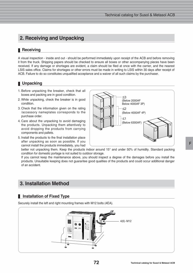
72 Technical catalog for Susol & Metasol ACB
Technical catalog for Susol & Metasol ACB
F
2. Receiving and Unpacking
3. Installation Method
Securely install the left and right mounting frames with M12 bolts (4EA).
Installation of Fixed Type
A visual inspection - inside and out - should be performed immediately upon receipt of the ACB and before removingit from the truck. Shipping papers should be checked to ensure all boxes or other accompanying pieces have beenreceived. If any damage or shortages are evident, a claim should be filed at once with the carrier, and the nearestLSIS sales office. Claims for shortages or other errors must be made in writing to LSIS within 30 days after receipt ofACB. Failure to do so constitutes unqualified acceptance and a waiver of all such claims by the purchaser.
Receiving
1. Before unpacking the breaker, check that all boxes and packing are in good condition.
2. While unpacking, check the breaker is in good condition.
3. Check that the information given on the rating /accessory nameplates corresponds to the purchase order.
4. Care about the unpacking to avoid damaging the products. Unpacking them attentively to avoid dropping the products from carrying components and pallets.
5. Install the products to the final installation place after unpacking as soon as possible. If you cannot install the products immediately, you had better not unpacking them. Keep the products indoor around 15° and under 50% of humidity. Standard packing condition for domestic portage is not suited to outdoor storage.If you cannot keep the maintenance above, you should inspect a degree of the damages before you install the products. Unsuitable keeping does not guarantee good qualities of the products and could occur additional dangerof an accident.
Unpacking
≤3(Below 2000AFBelow 4000AF 3P)
≤2(Below 4000AF 4P)
≤1(Below 6300AF)
4(6)-M12
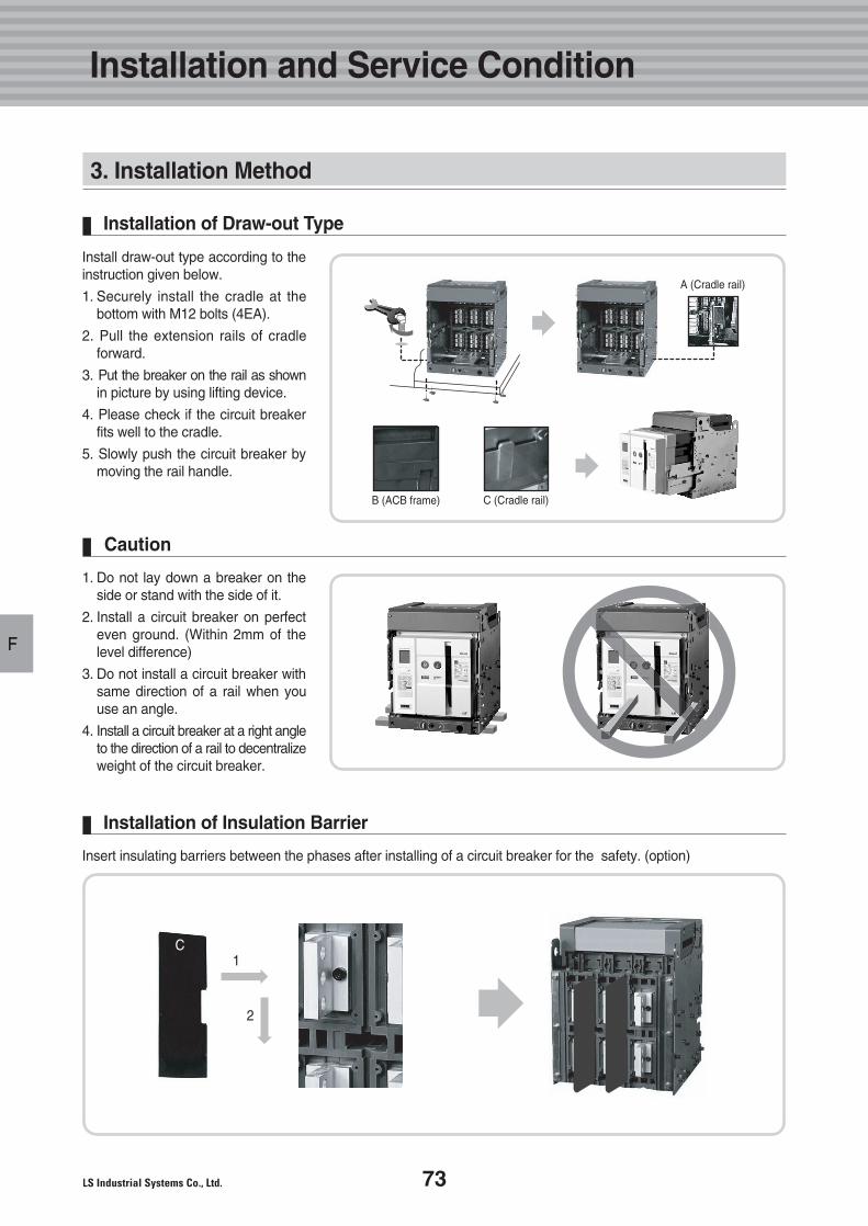
73
F
3. Installation Method
Install draw-out type according to theinstruction given below.
1. Securely install the cradle at the bottom with M12 bolts (4EA).
2. Pull the extension rails of cradle forward.
3. Put the breaker on the rail as shownin picture by using lifting device.
4. Please check if the circuit breakerfits well to the cradle.
5. Slowly push the circuit breaker by moving the rail handle.
Installation of Draw-out Type
1. Do not lay down a breaker on theside or stand with the side of it.
2. Install a circuit breaker on perfect even ground. (Within 2mm of the level difference)
3. Do not install a circuit breaker withsame direction of a rail when you use an angle.
4. Install a circuit breaker at a right angleto the direction of a rail to decentralizeweight of the circuit breaker.
Caution
Insert insulating barriers between the phases after installing of a circuit breaker for the safety. (option)
Installation of Insulation Barrier
A (Cradle rail)
B (ACB frame) C (Cradle rail)
C1
2
Installation and Service Condition
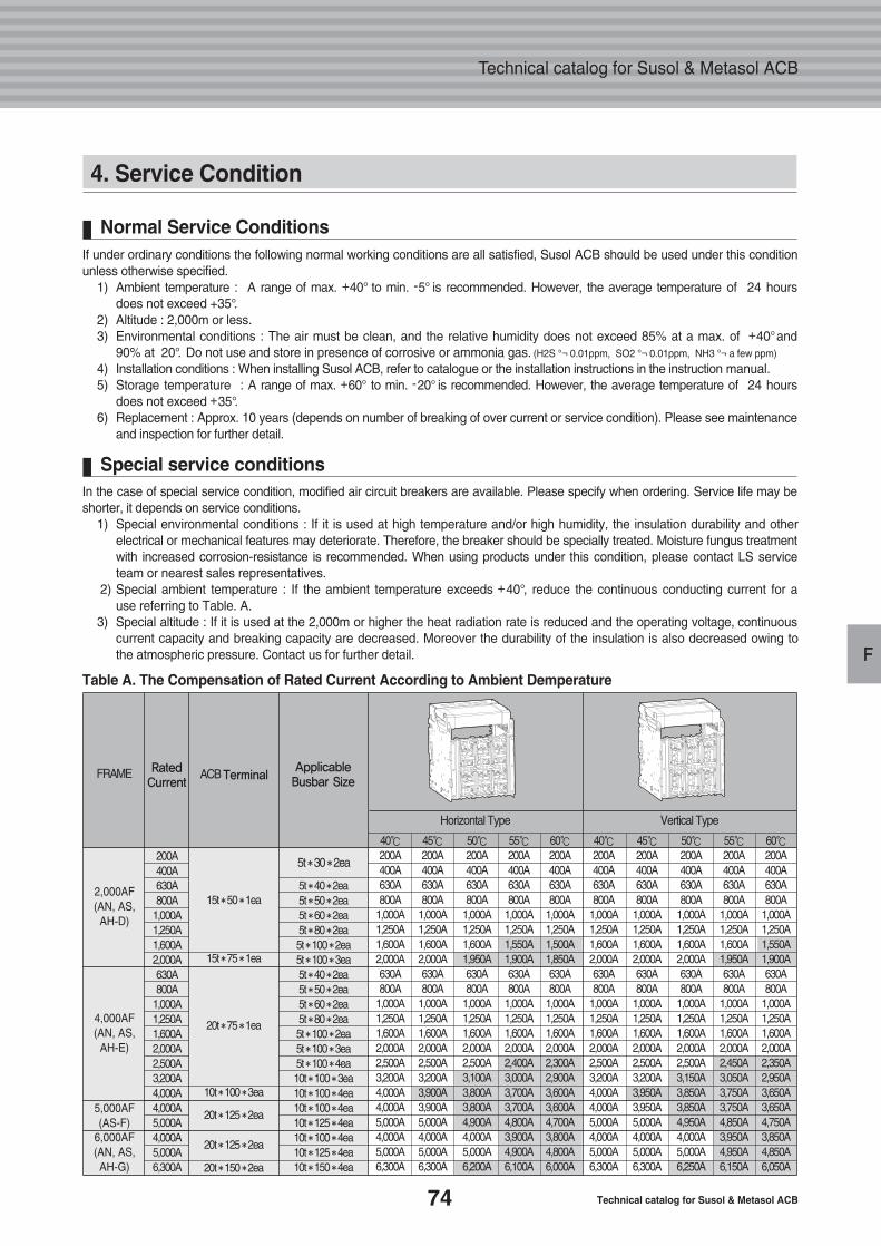
74 Technical catalog for Susol & Metasol ACB
Technical catalog for Susol & Metasol ACB
F
Table A. The Compensation of Rated Current According to Ambient Demperature
40℃200A400A630A800A
1,000A1,250A1,600A2,000A630A800A
1,000A1,250A1,600A2,000A2,500A3,200A4,000A4,000A5,000A4,000A5,000A6,300A
5t �40 �2ea5t �50 �2ea5t �60 �2ea5t �80 �2ea5t �100 �2ea5t �100 �3ea5t �40 �2ea5t �50 �2ea5t �60 �2ea5t �80 �2ea5t �100 �2ea5t �100 �3ea5t �100 �4ea10t �100 �3ea10t �100 �4ea10t �100 �4ea10t �125 �4ea10t �100 �4ea10t �125 �4ea10t �150 �4ea
200A400A630A800A
1,000A1,250A1,600A2,000A630A800A
1,000A1,250A1,600A2,000A2,500A3,200A4,000A4,000A5,000A4,000A5,000A6,300A
45℃200A400A630A800A
1,000A1,250A1,600A2,000A630A800A
1,000A1,250A1,600A2,000A2,500A3,200A3,900A3,900A5,000A4,000A5,000A6,300A
50℃200A400A630A800A
1,000A1,250A1,600A1,950A630A800A
1,000A1,250A1,600A2,000A2,500A3,100A3,800A3,800A4,900A4,000A5,000A6,200A
55℃200A400A630A800A
1,000A1,250A1,550A1,900A630A800A
1,000A1,250A1,600A2,000A2,400A3,000A3,700A3,700A4,800A3,900A4,900A6,100A
60℃200A400A630A800A
1,000A1,250A1,500A1,850A630A800A
1,000A1,250A1,600A2,000A2,300A2,900A3,600A3,600A4,700A3,800A4,800A6,000A
40℃200A400A630A800A
1,000A1,250A1,600A2,000A630A800A
1,000A1,250A1,600A2,000A2,500A3,200A4,000A4,000A5,000A4,000A5,000A6,300A
45℃200A400A630A800A
1,000A1,250A1,600A2,000A630A800A
1,000A1,250A1,600A2,000A2,500A3,200A3,950A3,950A5,000A4,000A5,000A6,300A
50℃200A400A630A800A
1,000A1,250A1,600A2,000A630A800A
1,000A1,250A1,600A2,000A2,500A3,150A3,850A3,850A4,950A4,000A5,000A6,250A
55℃200A400A630A800A
1,000A1,250A1,600A1,950A630A800A
1,000A1,250A1,600A2,000A2,450A3,050A3,750A3,750A4,850A3,950A4,950A6,150A
60℃200A400A630A800A
1,000A1,250A1,550A1,900A630A800A
1,000A1,250A1,600A2,000A2,350A2,950A3,650A3,650A4,750A3,850A4,850A6,050A
2,000AF(AN, AS,AH-D)
5,000AF(AS-F)
6,000AF(AN, AS,AH-G)
4,000AF(AN, AS,
AH-E)
FRAME RatedCurrent
ACB TerminalApplicableBusbar Size
5t �30 �2ea
Horizontal Type Vertical Type
15t �50 �1ea
15t �75 �1ea
10t �100 �3ea
20t �125 �2ea
20t �125 �2ea
20t �150 �2ea
20t �75 �1ea
4. Service Condition
If under ordinary conditions the following normal working conditions are all satisfied, Susol ACB should be used under this conditionunless otherwise specified.
1) Ambient temperature : A range of max. +40° to min. -5° is recommended. However, the average temperature of 24 hours does not exceed +35°.
2) Altitude : 2,000m or less.3) Environmental conditions : The air must be clean, and the relative humidity does not exceed 85% at a max. of +40°and
90% at 20°. Do not use and store in presence of corrosive or ammonia gas. (H2S °¬ 0.01ppm, SO2 °¬ 0.01ppm, NH3 °¬ a few ppm)
4) Installation conditions : When installing Susol ACB, refer to catalogue or the installation instructions in the instruction manual.5) Storage temperature : A range of max. +60° to min. -20° is recommended. However, the average temperature of 24 hours
does not exceed +35°.6) Replacement : Approx. 10 years (depends on number of breaking of over current or service condition). Please see maintenance
and inspection for further detail.
Normal Service Conditions
In the case of special service condition, modified air circuit breakers are available. Please specify when ordering. Service life may beshorter, it depends on service conditions.
1) Special environmental conditions : If it is used at high temperature and/or high humidity, the insulation durability and other electrical or mechanical features may deteriorate. Therefore, the breaker should be specially treated. Moisture fungus treatmentwith increased corrosion-resistance is recommended. When using products under this condition, please contact LS service team or nearest sales representatives.
2) Special ambient temperature : If the ambient temperature exceeds +40°, reduce the continuous conducting current for a use referring to Table. A.
3) Special altitude : If it is used at the 2,000m or higher the heat radiation rate is reduced and the operating voltage, continuous current capacity and breaking capacity are decreased. Moreover the durability of the insulation is also decreased owing to the atmospheric pressure. Contact us for further detail.
Special service conditions
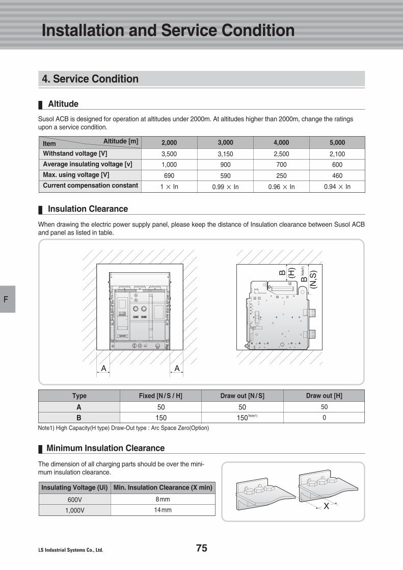
75
F
Susol ACB is designed for operation at altitudes under 2000m. At altitudes higher than 2000m, change the ratingsupon a service condition.
Altitude
2,000Altitude [m]Item 3,000 4,000 5,000
Withstand voltage [V]
Average insulating voltage [v]
Max. using voltage [V]
Current compensation constant
3,500
1,000
690
1 × In
3,150
900
590
0.99 × In
2,500
700
250
0.96 × In
2,100
600
460
0.94 × In
When drawing the electric power supply panel, please keep the distance of Insulation clearance between Susol ACBand panel as listed in table.
Insulation Clearance
Min. Insulation Clearance (X min)Insulating Voltage (Ui)
600V
1,000V
The dimension of all charging parts should be over the mini-mum insulation clearance.
Minimum Insulation Clearance
Installation and Service Condition
4. Service Condition
Fixed [H]
50150
Draw out [H]
50
0
Note1) High Capacity(H type) Draw-Out type : Arc Space Zero(Option)
Fixed [N / S / H]Type
AB
50150
Draw out [N / S] Draw out [H]
Not
e1)
Note1)
8mm
14mm
G.Operation
77
78
79
80
1. Manual Operation
2. Electrical Operation
3. Draw-in Operation
4. Draw-out Operation
76 Technical catalog for Susol & Metasol ACB
Technical catalog for Susol & Metasol ACB
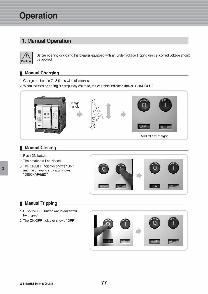
77
G
1. Manual Operation
1. Charge the handle 7~ 8 times with full strokes.
2. When the closing spring is completely charged, the charging indicator shows ‘‘CHARGED’’.
Manual Charging
1. Push ON button.
2. The breaker will be closed.
3. The ON/OFF indicator shows ‘‘ON’’and the charging indicator shows‘‘DISCHARGED’’.
Manual Closing
1. Push the OFF button and breaker will be tripped.
2. The ON/OFF indicator shows ‘‘OFF’’
Manual Tripping
Before opening or closing the breaker equipped with an under voltage tripping device, control voltage shouldbe applied.Caution
Chargehandle
ACB off and charged
Operation
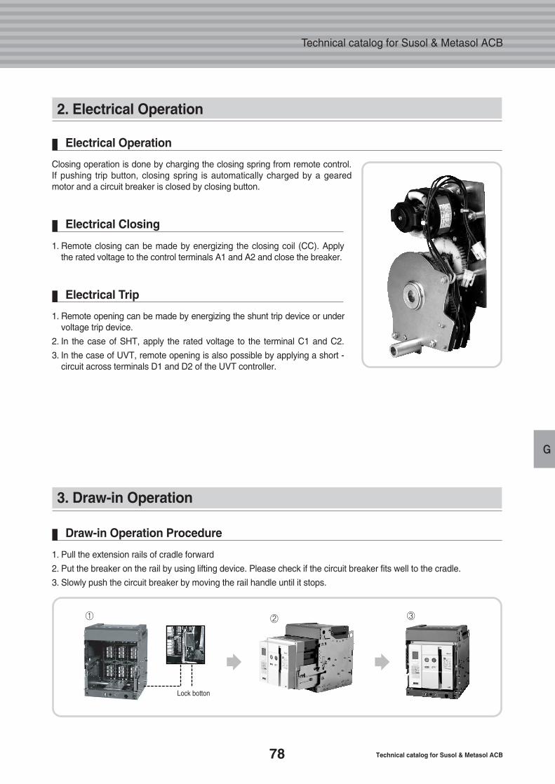
78 Technical catalog for Susol & Metasol ACB
Technical catalog for Susol & Metasol ACB
G
2. Electrical Operation
3. Draw-in Operation
Closing operation is done by charging the closing spring from remote control. If pushing trip button, closing spring is automatically charged by a geared motor and a circuit breaker is closed by closing button.
Electrical Operation
1. Remote closing can be made by energizing the closing coil (CC). Apply the rated voltage to the control terminals A1 and A2 and close the breaker.
Electrical Closing
1. Remote opening can be made by energizing the shunt trip device or undervoltage trip device.
2. In the case of SHT, apply the rated voltage to the terminal C1 and C2.
3. In the case of UVT, remote opening is also possible by applying a short -circuit across terminals D1 and D2 of the UVT controller.
Electrical Trip
1. Pull the extension rails of cradle forward
2. Put the breaker on the rail by using lifting device. Please check if the circuit breaker fits well to the cradle.
3. Slowly push the circuit breaker by moving the rail handle until it stops.
Draw-in Operation Procedure
Lock botton
① ② ③
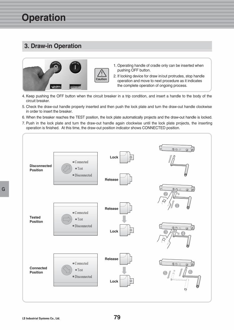
79
G
1. 수동조작
4. Keep pushing the OFF button when the circuit breaker in a trip condition, and insert a handle to the body of the circuit breaker.
5. Check the draw-out handle properly inserted and then push the lock plate and turn the draw-out handle clockwise in order to insert the breaker.
6. When the breaker reaches the TEST position, the lock plate automatically projects and the draw-out handle is locked.
7. Push in the lock plate and turn the draw-out handle again clockwise until the lock plate projects, the inserting operation is finished. At this time, the draw-out position indicator shows CONNECTED position.
1. Operating handle of cradle only can be inserted when pushing OFF button.
2. If locking device for draw in/out protrudes, stop handleoperation and move to next procedure as it indicates the complete operation of ongoing process.
Caution
3. Draw-in Operation
DisconnectedPosition
TestedPosition
ConnectedPosition
Operation
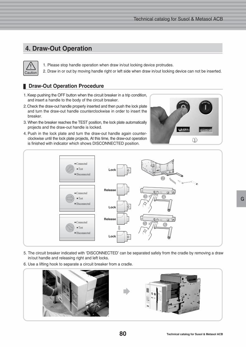
80 Technical catalog for Susol & Metasol ACB
Technical catalog for Susol & Metasol ACB
G
4. Draw-Out Operation
1. Please stop handle operation when draw in/out locking device protrudes.
2. Draw in or out by moving handle right or left side when draw in/out locking device can not be inserted.Caution
1. Keep pushing the OFF button when the circuit breaker in a trip condition,and insert a handle to the body of the circuit breaker.
2.Check the draw-out handle properly inserted and then push the lock plateand turn the draw-out handle counterclockwise in order to insert the breaker.
3. When the breaker reaches the TEST position, the lock plate automaticallyprojects and the draw-out handle is locked.
4. Push in the lock plate and turn the draw-out handle again counter-clockwise until the lock plate projects, At this time, the draw-out operationis finished with indicator which shows DISCONNECTED position.
5. The circuit breaker indicated with ‘DISCONNECTED’ can be separated safely from the cradle by removing a drawin/out handle and releasing right and left locks.
6. Use a lifting hook to separate a circuit breaker from a cradle.
Draw-Out Operation Procedure
82
83
88
1. Protective Coordination
2. Selectivity Techniques
3. Discrimination Table
H. ProtectiveCoordination
81
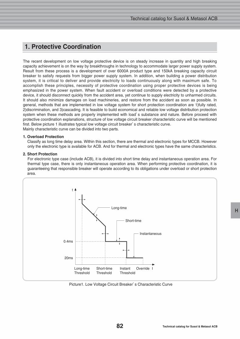
82 Technical catalog for Susol & Metasol ACB
Technical catalog for Susol & Metasol ACB
H
The recent development on low voltage protective device is on steady increase in quantity and high breakingcapacity achievement is on the way by breakthroughs in technology to accommodate larger power supply system.Result from these process is a development of over 6000A product type and 150kA breaking capacity circuitbreaker to satisfy requests from bigger power supply system. In addition, when building a power distributionsystem, it is critical to deliver and provide electricity to loads continuously along with maximum safe. Toaccomplish these principles, necessity of protective coordination using proper protective devices is beingemphasized in the power system. When fault accident or overload conditions were detected by a protectivedevice, it should disconnect quickly from the accident area, yet continue to supply electricity to unharmed circuits.It should also minimize damages on load machineries, and restore from the accident as soon as possible. Ingeneral, methods that are implemented in low voltage system for short protection coordination are 1)fully rated,2)discrimination, and 3)cascading. It is feasible to build economical and reliable low voltage distribution protectionsystem when these methods are properly implemented with load’s substance and nature. Before proceed withprotective coordination explanations, structure of low voltage circuit breaker characteristic curve will be mentionedfirst. Below picture 1 illustrates typical low voltage circuit breaker’s characteristic curve. Mainly characteristic curve can be divided into two parts.
1. Overload ProtectionClassify as long time delay area. Within this section, there are thermal and electronic types for MCCB. Howeveronly the electronic type is available for ACB. And for thermal and electronic types have the same characteristics.
2. Short ProtectionFor electronic type case (include ACB), it is divided into short time delay and instantaneous operation area. Forthermal type case, there is only instantaneous operation area. When performing protective coordination, it isguaranteeing that responsible breaker will operate according to its obligations under overload or short protectionarea.
1. Protective Coordination
Picture1. Low Voltage Circuit Breaker’s Characteristic Curve
Long-time
Short-time
Instantaneous
Long-timeThreshold
Short-timeThreshold
InstantThreshold
Override I
t
0.4ms
20ms
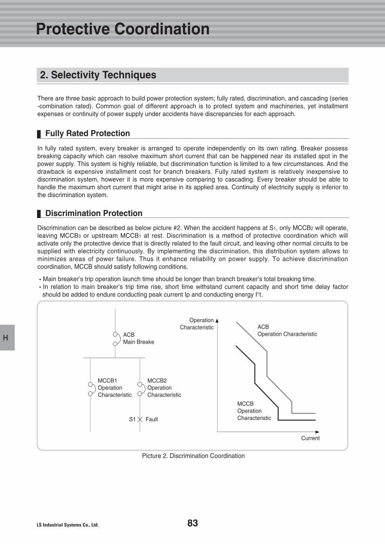
83
H
2. Selectivity Techniques
Discrimination can be described as below picture #2. When the accident happens at S1, only MCCB2 will operate,leaving MCCB3 or upstream MCCB1 at rest. Discrimination is a method of protective coordination which willactivate only the protective device that is directly related to the fault circuit, and leaving other normal circuits to besupplied with electricity continuously. By implementing the discrimination, this distribution system allows tominimizes areas of power failure. Thus it enhance reliability on power supply. To achieve discriminationcoordination, MCCB should satisfy following conditions.
�Main breaker’s trip operation launch time should be longer than branch breaker’s total breaking time. �In relation to main breaker’s trip time rise, short time withstand current capacity and short time delay factor
should be added to endure conducting peak current Ip and conducting energy I2t.
In fully rated system, every breaker is arranged to operate independently on its own rating. Breaker possessbreaking capacity which can resolve maximum short current that can be happened near its installed spot in thepower supply. This system is highly reliable, but discrimination function is limited to a few circumstances. And thedrawback is expensive installment cost for branch breakers. Fully rated system is relatively inexpensive todiscrimination system, however it is more expensive comparing to cascading. Every breaker should be able tohandle the maximum short current that might arise in its applied area. Continuity of electricity supply is inferior tothe discrimination system.
There are three basic approach to build power protection system; fully rated, discrimination, and cascading (series-combination rated). Common goal of different approach is to protect system and machineries, yet installmentexpenses or continuity of power supply under accidents have discrepancies for each approach.
Discrimination Protection
Fully Rated Protection
Picture 2. Discrimination Coordination
ACBMain Breake
ACBOperation Characteristic
MCCB1OperationCharacteristic
MCCB2OperationCharacteristic
MCCBOperationCharacteristicS1 Fault
Current
OperationCharacteristic
Protective Coordination
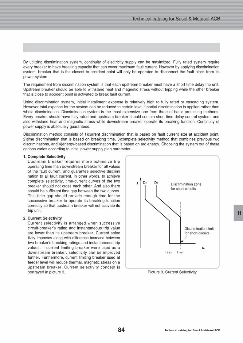
84 Technical catalog for Susol & Metasol ACB
Technical catalog for Susol & Metasol ACB
H
By utilizing discrimination system, continuity of electricity supply can be maximized. Fully rated system requireevery breaker to have breaking capacity that can cover maximum fault current. However by applying discriminationsystem, breaker that is the closest to accident point will only be operated to disconnect the fault block from its power system.
The requirement from discrimination system is that each upstream breaker must have a short time delay trip unit. Upstream breaker should be able to withstand heat and magnetic stress without tripping while the other breakerthat is close to accident point is activated to break fault current.
Using discrimination system, initial installment expense is relatively high to fully rated or cascading system.However total expense for the system can be reduced to certain level if partial discrimination is applied rather thanwhole discrimination. Discrimination system is the most expensive one from three of basic protecting methods.Every breaker should have fully rated and upstream breaker should contain short time delay control system, and also withstand heat and magnetic stress while downstream breaker operate its breaking function. Continuity of power supply is absolutely guaranteed.
Discrimination method consists of 1)current discrimination that is based on fault current size at accident point,2)time discrimination that is based on breaking time, 3)complete selectivity method that combines previous two discriminations, and 4)energy-based discrimination that is based on arc energy. Choosing the system out of theseoptions varies according to initial power supply plan parameter.
1. Complete SelectivityUpstream breaker requires more extensive tripoperating time than downstream breaker for all valuesof the fault current, and guarantee selective discrimination to all fault current. In other words, to achieve complete selectivity, time-current curves of the twobreaker should not cross each other. And also thereshould be sufficient time gap between the two curves.This time gap should provide enough time for thesuccessive breaker to operate its breaking functioncorrectly so that upstream breaker will not activate itstrip unit.
2. Current SelectivityCurrent selectivity is arranged when successivecircuit-breaker’s rating and instantaneous trip valueare lower than its upstream breaker. Current selectivity improves along with difference increase between two breaker’s breaking ratings and instantaneous trip values. If current limiting breaker were used as adownstream breaker, selectivity can be improvedfurther. Furthermore, current limiting breaker used atfeeder level will reduce thermal, magnetic stress on a upstream breaker. Current selectivity concept isportrayed in picture 3. Picture 3. Current Selectivity
Discrimination zone for short-circuits
D2t
II ins2 I ins1
D1
Discrimination limitfor short-circuits
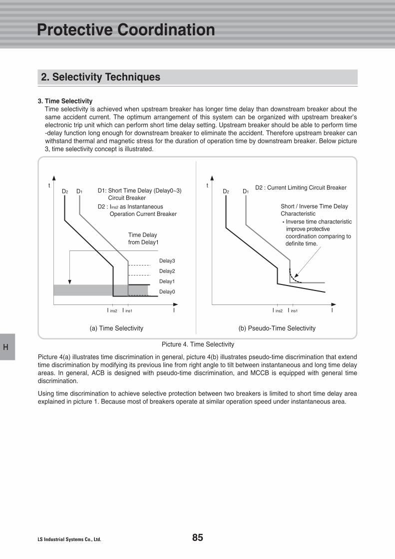
85
H
3. Time Selectivity Time selectivity is achieved when upstream breaker has longer time delay than downstream breaker about thesame accident current. The optimum arrangement of this system can be organized with upstream breaker’selectronic trip unit which can perform short time delay setting. Upstream breaker should be able to perform time-delay function long enough for downstream breaker to eliminate the accident. Therefore upstream breaker canwithstand thermal and magnetic stress for the duration of operation time by downstream breaker. Below picture3, time selectivity concept is illustrated.
Picture 4(a) illustrates time discrimination in general, picture 4(b) illustrates pseudo-time discrimination that extendtime discrimination by modifying its previous line from right angle to tilt between instantaneous and long time delayareas. In general, ACB is designed with pseudo-time discrimination, and MCCB is equipped with general timediscrimination.
Using time discrimination to achieve selective protection between two breakers is limited to short time delay areaexplained in picture 1. Because most of breakers operate at similar operation speed under instantaneous area.
Picture 4. Time Selectivity
(a) Time Selectivity (b) Pseudo-Time Selectivity
D1: Short Time Delay (Delay0~3)Circuit Breaker
D2 : Current Limiting Circuit Breaker
D2 : Iins2 as InstantaneousOperation Current Breaker
Time Delayfrom Delay1
Delay3
Delay2
Delay1
Delay0
Short / Inverse Time Delay Characteristic�Inverse time characteristic
improve protectivecoordination comparing to definite time.
D2 D1
t
I ins2 I ins1 I
D2 D1
t
I ins2 I ins1 I
Protective Coordination
2. Selectivity Techniques
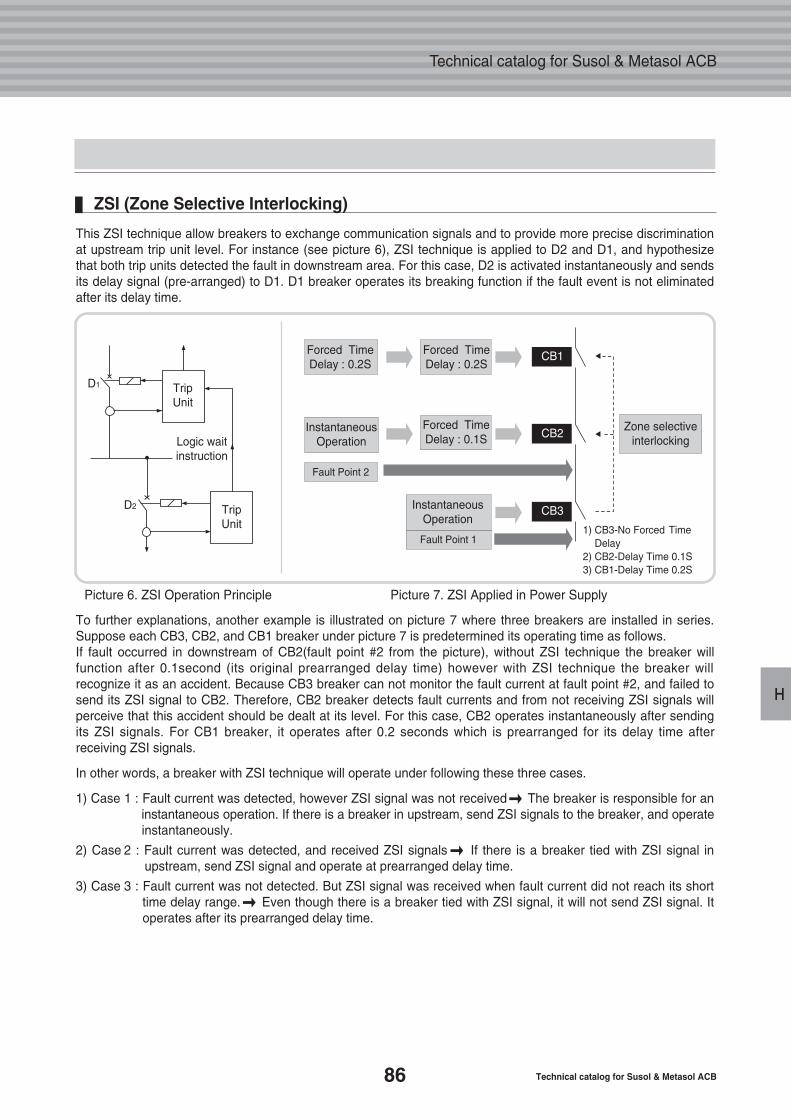
86 Technical catalog for Susol & Metasol ACB
Technical catalog for Susol & Metasol ACB
H
Picture 6. ZSI Operation Principle Picture 7. ZSI Applied in Power Supply
This ZSI technique allow breakers to exchange communication signals and to provide more precise discriminationat upstream trip unit level. For instance (see picture 6), ZSI technique is applied to D2 and D1, and hypothesizethat both trip units detected the fault in downstream area. For this case, D2 is activated instantaneously and sendsits delay signal (pre-arranged) to D1. D1 breaker operates its breaking function if the fault event is not eliminatedafter its delay time.
ZSI (Zone Selective Interlocking)
To further explanations, another example is illustrated on picture 7 where three breakers are installed in series.Suppose each CB3, CB2, and CB1 breaker under picture 7 is predetermined its operating time as follows.If fault occurred in downstream of CB2(fault point #2 from the picture), without ZSI technique the breaker willfunction after 0.1second (its original prearranged delay time) however with ZSI technique the breaker willrecognize it as an accident. Because CB3 breaker can not monitor the fault current at fault point #2, and failed tosend its ZSI signal to CB2. Therefore, CB2 breaker detects fault currents and from not receiving ZSI signals willperceive that this accident should be dealt at its level. For this case, CB2 operates instantaneously after sendingits ZSI signals. For CB1 breaker, it operates after 0.2 seconds which is prearranged for its delay time afterreceiving ZSI signals.
In other words, a breaker with ZSI technique will operate under following these three cases.
1) Case 1 : Fault current was detected, however ZSI signal was not received � The breaker is responsible for aninstantaneous operation. If there is a breaker in upstream, send ZSI signals to the breaker, and operateinstantaneously.
2) Case 2 : Fault current was detected, and received ZSI signals � If there is a breaker tied with ZSI signal inupstream, send ZSI signal and operate at prearranged delay time.
3) Case 3 : Fault current was not detected. But ZSI signal was received when fault current did not reach its short time delay range. � Even though there is a breaker tied with ZSI signal, it will not send ZSI signal. Itoperates after its prearranged delay time.
1) CB3-No Forced TimeDelay
2) CB2-Delay Time 0.1S3) CB1-Delay Time 0.2S
Forced TimeDelay : 0.2S
Forced TimeDelay : 0.2S
CB1
CB2
CB3
InstantaneousOperationLogic wait
instruction
D1
D2
TripUnit
TripUnit
InstantaneousOperation
Fault Point 2
Fault Point 1
Forced TimeDelay : 0.1S
Zone selectiveinterlocking
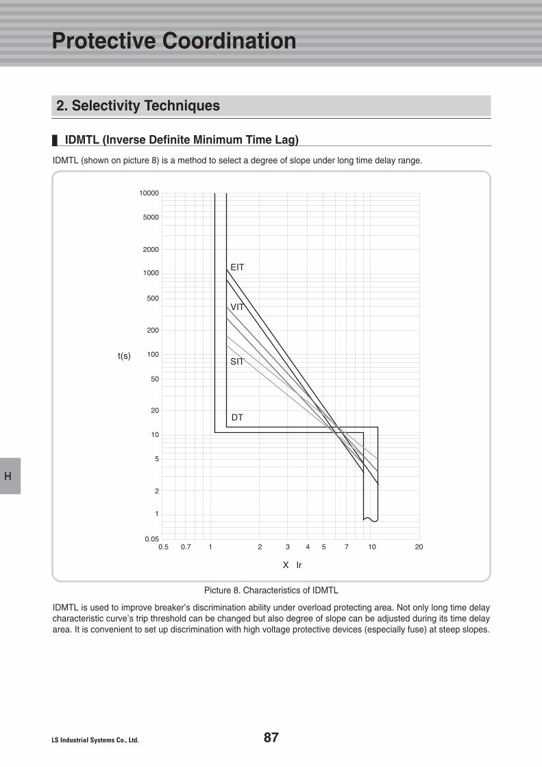
87
H
Picture 8. Characteristics of IDMTL
IDMTL (shown on picture 8) is a method to select a degree of slope under long time delay range.
IDMTL is used to improve breaker’s discrimination ability under overload protecting area. Not only long time delaycharacteristic curve’s trip threshold can be changed but also degree of slope can be adjusted during its time delayarea. It is convenient to set up discrimination with high voltage protective devices (especially fuse) at steep slopes.
IDMTL (Inverse Definite Minimum Time Lag)
Protective Coordination
2. Selectivity Techniques
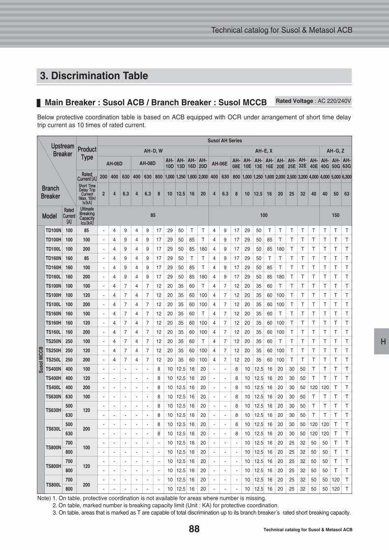
88 Technical catalog for Susol & Metasol ACB
Technical catalog for Susol & Metasol ACB
H
3. Discrimination Table
Main Breaker : Susol ACB / Branch Breaker : Susol MCCB
Below protective coordination table is based on ACB equipped with OCR under arrangement of short time delaytrip current as 10 times of rated current.
Note) 1. On table, protective coordination is not available for areas where number is missing.2. On table, marked number is breaking capacity limit (Unit : KA) for protective coordination. 3. On table, areas that is marked as T are capable of total discrimination up to its branch breaker’s rated short breaking capacity.
Rated Voltage : AC 220/240V
TD100N 100 85
TD100H 100 100
TD100L 100 200
TD160N 160 85
TD160H 160 100
TD160L 160 200
TS100N 100 100
TS100H 100 120
TS100L 100 200
TS160N 160 100
TS160H 160 120
TS160L 160 200
TS250N 250 100
TS250H 250 120
TS250L 250 200
TS400N 400 100
TS400H 400 120
TS400L 400 200
TS630N 630 100
500
630
500
630
700
800
700
800
700
800
TS630H 120
TS630L 200
TS800N 100
TS800H 120
TS800L 200
Susol AH Series
AH-D, W
AH-06D AH-08D AH-06EAH-10D
AH-13D
AH-16D
AH-20D
AH-08E
AH-10E
AH-13E
AH-16E
AH-20E
AH-25E
AH-32E
AH-40G
AH-50G
AH-63G
AH-40E
AH-E, X AH-G, Z
200 400 630 400 630 800 1,000 1,250 1,600 2,000 400 630
2 4 6.3 4 6.3 8 10 12.5 16 20 4 6.3
800 1,000 1,250 1,600 2,000 2,500 3,200 4,000 4,000 5,000 6,300
8 10 12.5 16 20 25 32 40 40 50 63
- 4 9 4 9 17 29 50 T T 4 9 17 29 50 T T T T T
- 4 9 4 9 17 29 50 85 T 4 9 17 29 50 85 T T T T
- 4 9 4 9 17 29 50 85 180 4 9 17 29 50 85 180 T T T
- 4 9 4 9 17 29 50 T T 4 9 17 29 50 T T T T T
- 4 9 4 9 17 29 50 85 T 4 9 17 29 50 85 T T T T
- 4 9 4 9 17 29 50 85 180 4 9 17 29 50 85 180 T T T
- 4 7 4 7 12 20 35 60 T 4 7 12 20 35 60 T T T T
- 4 7 4 7 12 20 35 60 100 4 7 12 20 35 60 100 T T T
- 4 7 4 7 12 20 35 60 100 4 7 12 20 35 60 100 T T T
- 4 7 4 7 12 20 35 60 T 4 7 12 20 35 60 T T T T
- 4 7 4 7 12 20 35 60 100 4 7 12 20 35 60 100 T T T
- 4 7 4 7 12 20 35 60 100 4 7 12 20 35 60 100 T T T
- 4 7 4 7 12 20 35 60 T 4 7 12 20 35 60 T T T T
- 4 7 4 7 12 20 35 60 100 4 7 12 20 35 60 100 T T T
- 4 7 4 7 12 20 35 60 100 4 7 12 20 35 60 100 T T T
- - - - - 8 10 12.5 16 20 - - 8 10 12.5 16 20 30 50 T
- - - - - 8 10 12.5 16 20 - - 8 10 12.5 16 20 30 50 T
- - - - - 8 10 12.5 16 20 - - 8 10 12.5 16 20 30 50 120
- - - - - 8 10 12.5 16 20 - - 8 10 12.5 16 20 30 50 T
- - - - - 8 10 12.5 16 20 - - 8 10 12.5 16 20 30 50 T
- - - - - 8 10 12.5 16 20 - - 8 10 12.5 16 20 30 50 T
- - - - - 8 10 12.5 16 20 - - 8 10 12.5 16 20 30 50 120
- - - - - 8 10 12.5 16 20 - - 8 10 12.5 16 20 30 50 120
- - - - - - 10 12.5 16 20 - - - 10 12.5 16 20 25 32 50
- - - - - - 10 12.5 16 20 - - - 10 12.5 16 20 25 32 50
- - - - - - 10 12.5 16 20 - - - 10 12.5 16 20 25 32 50
- - - - - - 10 12.5 16 20 - - - 10 12.5 16 20 25 32 50
- - - - - - 10 12.5 16 20 - - - 10 12.5 16 20 25 32 50
- - - - - - 10 12.5 16 20 - - - 10 12.5 16 20 25 32 50
T T T
T T T
T T T
T T T
T T T
T T T
T T T
T T T
T T T
T T T
T T T
T T T
T T T
T T T
T T T
T T T
T T T
120 T T
T T T
T T T
T T T
120 T T
120 T T
50 T T
50 T T
50 T T
50 T T
50 120 T
50 120 T
85 100 150
Suso
lMC
CB
ModelRatedCurrent
[A]
RatedCurrent[A]
Short TimeDelay TripCurrent
(Max. 10In)Is[kA]
ProductType
UpstreamBreaker
BranchBreaker
UltimateBreakingCapacityIcu[kA]
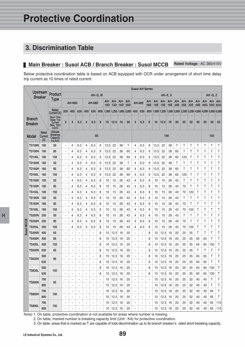
89
H
Protective Coordination
3. Discrimination Table
Main Breaker : Susol ACB / Branch Breaker : Susol MCCB
Below protective coordination table is based on ACB equipped with OCR under arrangement of short time delaytrip current as 10 times of rated current.
Note) 1. On table, protective coordination is not available for areas where number is missing.2. On table, marked number is breaking capacity limit (Unit : KA) for protective coordination. 3. On table, areas that is marked as T are capable of total discrimination up to its branch breaker’s rated short breaking capacity.
Rated Voltage : AC 380/415V
TD100N 100 50
TD100H 100 85
TD100L 100 150
TD160N 160 50
TD160H 160 85
TD160L 160 150
TS100N 100 50
TS100H 100 85
TS100L 100 150
TS160N 160 50
TS160H 160 85
TS160L 160 150
TS250N 250 50
TS250H 250 85
TS250L 250 150
TS400N 400 65
TS400H 400 85
TS400L 400 150
TS630N 630 65
500
630
500
630
700
800
700
800
700
800
TS630H 85
TS630L 150
TS800N 65
TS800H 100
TS800L 150
Susol AH Series
AH-D, W
AH-06D AH-08D AH-06EAH-10D
AH-13D
AH-16D
AH-20D
AH-08E
AH-10E
AH-13E
AH-16E
AH-20E
AH-25E
AH-32E
AH-40G
AH-50G
AH-63G
AH-40E
AH-E, X AH-G, Z
200 400 630 400 630 800 1,000 1,250 1,600 2,000 400 630
2 4 6.3 4 6.3 8 10 12.5 16 20 4 6.3
800 1,000 1,250 1,600 2,000 2,500 3,200 4,000 4,000 5,000 6,300
8 10 12.5 16 20 25 32 40 40 50 63
- 4 6.3 4 6.3 9 13.5 22 38 T 4 6.3 9 13.5 22 38 T T T T
- 4 6.3 4 6.3 9 13.5 22 38 60 4 6.3 9 13.5 22 38 60 T T T
- 4 6.3 4 6.3 9 13.5 22 38 60 4 6.3 9 13.5 22 38 60 120 T T
- 4 6.3 4 6.3 9 13.5 22 38 T 4 6.3 9 13.5 22 38 T T T T
- 4 6.3 4 6.3 9 13.5 22 38 60 4 6.3 9 13.5 22 38 60 T T T
- 4 6.3 4 6.3 9 13.5 22 38 60 4 6.3 9 13.5 22 38 60 120 T T
- 4 6.3 4 6.3 8 10 15 26 43 4 6.3 8 10 15 26 43 T T T
- 4 6.3 4 6.3 8 10 15 26 43 4 6.3 8 10 15 26 43 70 T T
- 4 6.3 4 6.3 8 10 15 26 43 4 6.3 8 10 15 26 43 70 120 T
- 4 6.3 4 6.3 8 10 15 26 43 4 6.3 8 10 15 26 43 T T T
- 4 6.3 4 6.3 8 10 15 26 43 4 6.3 8 10 15 26 43 70 T T
- 4 6.3 4 6.3 8 10 15 26 43 4 6.3 8 10 15 26 43 70 120 T
- 4 6.3 4 6.3 8 10 15 26 43 4 6.3 8 10 15 26 43 T T T
- 4 6.3 4 6.3 8 10 15 26 43 4 6.3 8 10 15 26 43 70 T T
- 4 6.3 4 6.3 8 10 15 26 43 4 6.3 8 10 15 26 43 70 120 T
- - - - - 8 10 12.5 16 20 - - 8 10 12.5 16 20 25 35 T
- - - - - 8 10 12.5 16 20 - - 8 10 12.5 16 20 25 35 65
- - - - - 8 10 12.5 16 20 - - 8 10 12.5 16 20 25 35 65
- - - - - 8 10 12.5 16 20 - - 8 10 12.5 16 20 25 35 T
- - - - - 8 10 12.5 16 20 - - 8 10 12.5 16 20 25 35 65
- - - - - 8 10 12.5 16 20 - - 8 10 12.5 16 20 25 35 65
- - - - - 8 10 12.5 16 20 - - 8 10 12.5 16 20 25 35 65
- - - - - 8 10 12.5 16 20 - - 8 10 12.5 16 20 25 35 65
- - - - - - 10 12.5 16 20 - - - 10 12.5 16 20 25 32 40
- - - - - - 10 12.5 16 20 - - - 10 12.5 16 20 25 32 40
- - - - - - 10 12.5 16 20 - - - 10 12.5 16 20 25 32 40
- - - - - - 10 12.5 16 20 - - - 10 12.5 16 20 25 32 40
- - - - - - 10 12.5 16 20 - - - 10 12.5 16 20 25 32 40
- - - - - - 10 12.5 16 20 - - - 10 12.5 16 20 25 32 40
T T T
T T T
T T T
T T T
T T T
T T T
T T T
T T T
T T T
T T T
T T T
T T T
T T T
T T T
T T T
T T T
65 T T
65 130 T
T T T
65 T T
65 T T
65 130 T
65 130 T
40 T T
40 T T
40 65 T
40 65 T
40 65 110
40 65 110
85 100 150
Suso
lMC
CB
ModelRatedCurrent
[A]
RatedCurrent[A]
Short TimeDelay TripCurrent
(Max. 10In)Is[kA]
ProductType
UpstreamBreaker
BranchBreaker
UltimateBreakingCapacityIcu[kA]
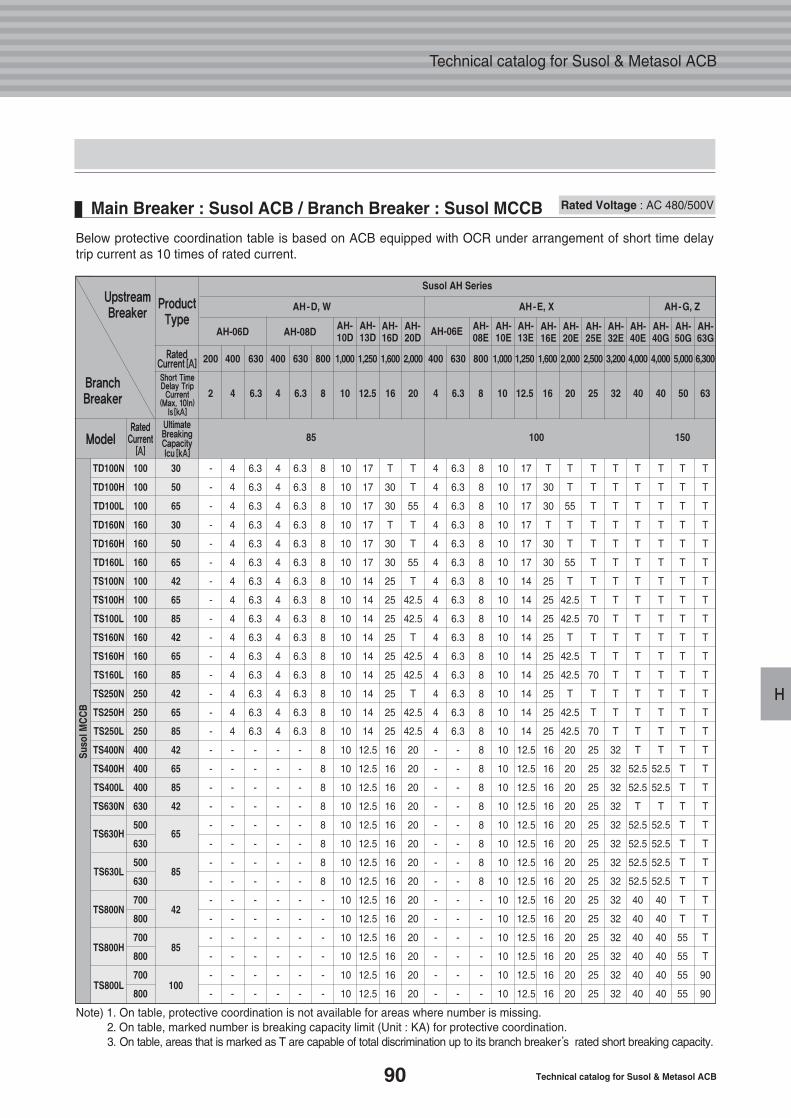
90 Technical catalog for Susol & Metasol ACB
Technical catalog for Susol & Metasol ACB
H
Main Breaker : Susol ACB / Branch Breaker : Susol MCCB
Below protective coordination table is based on ACB equipped with OCR under arrangement of short time delaytrip current as 10 times of rated current.
Note) 1. On table, protective coordination is not available for areas where number is missing.2. On table, marked number is breaking capacity limit (Unit : KA) for protective coordination. 3. On table, areas that is marked as T are capable of total discrimination up to its branch breaker’s rated short breaking capacity.
Rated Voltage : AC 480/500V
TD100N 100 30
TD100H 100 50
TD100L 100 65
TD160N 160 30
TD160H 160 50
TD160L 160 65
TS100N 100 42
TS100H 100 65
TS100L 100 85
TS160N 160 42
TS160H 160 65
TS160L 160 85
TS250N 250 42
TS250H 250 65
TS250L 250 85
TS400N 400 42
TS400H 400 65
TS400L 400 85
TS630N 630 42
500
630
500
630
700
800
700
800
700
800
TS630H 65
TS630L 85
TS800N 42
TS800H 85
TS800L 100
Susol AH Series
AH-D, W
AH-06D AH-08D AH-06EAH-10D
AH-13D
AH-16D
AH-20D
AH-08E
AH-10E
AH-13E
AH-16E
AH-20E
AH-25E
AH-32E
AH-40G
AH-50G
AH-63G
AH-40E
AH-E, X AH-G, Z
200 400 630 400 630 800 1,000 1,250 1,600 2,000 400 630
2 4 6.3 4 6.3 8 10 12.5 16 20 4 6.3
800 1,000 1,250 1,600 2,000 2,500 3,200 4,000 4,000 5,000 6,300
8 10 12.5 16 20 25 32 40 40 50 63
- 4 6.3 4 6.3 8 10 17 T T 4 6.3 8 10 17 T T T T T
- 4 6.3 4 6.3 8 10 17 30 T 4 6.3 8 10 17 30 T T T T
- 4 6.3 4 6.3 8 10 17 30 55 4 6.3 8 10 17 30 55 T T T
- 4 6.3 4 6.3 8 10 17 T T 4 6.3 8 10 17 T T T T T
- 4 6.3 4 6.3 8 10 17 30 T 4 6.3 8 10 17 30 T T T T
- 4 6.3 4 6.3 8 10 17 30 55 4 6.3 8 10 17 30 55 T T T
- 4 6.3 4 6.3 8 10 14 25 T 4 6.3 8 10 14 25 T T T T
- 4 6.3 4 6.3 8 10 14 25 42.5 4 6.3 8 10 14 25 42.5 T T T
- 4 6.3 4 6.3 8 10 14 25 42.5 4 6.3 8 10 14 25 42.5 70 T T
- 4 6.3 4 6.3 8 10 14 25 T 4 6.3 8 10 14 25 T T T T
- 4 6.3 4 6.3 8 10 14 25 42.5 4 6.3 8 10 14 25 42.5 T T T
- 4 6.3 4 6.3 8 10 14 25 42.5 4 6.3 8 10 14 25 42.5 70 T T
- 4 6.3 4 6.3 8 10 14 25 T 4 6.3 8 10 14 25 T T T T
- 4 6.3 4 6.3 8 10 14 25 42.5 4 6.3 8 10 14 25 42.5 T T T
- 4 6.3 4 6.3 8 10 14 25 42.5 4 6.3 8 10 14 25 42.5 70 T T
- - - - - 8 10 12.5 16 20 - - 8 10 12.5 16 20 25 32 T
- - - - - 8 10 12.5 16 20 - - 8 10 12.5 16 20 25 32 52.5
- - - - - 8 10 12.5 16 20 - - 8 10 12.5 16 20 25 32 52.5
- - - - - 8 10 12.5 16 20 - - 8 10 12.5 16 20 25 32 T
- - - - - 8 10 12.5 16 20 - - 8 10 12.5 16 20 25 32 52.5
- - - - - 8 10 12.5 16 20 - - 8 10 12.5 16 20 25 32 52.5
- - - - - 8 10 12.5 16 20 - - 8 10 12.5 16 20 25 32 52.5
- - - - - 8 10 12.5 16 20 - - 8 10 12.5 16 20 25 32 52.5
- - - - - - 10 12.5 16 20 - - - 10 12.5 16 20 25 32 40
- - - - - - 10 12.5 16 20 - - - 10 12.5 16 20 25 32 40
- - - - - - 10 12.5 16 20 - - - 10 12.5 16 20 25 32 40
- - - - - - 10 12.5 16 20 - - - 10 12.5 16 20 25 32 40
- - - - - - 10 12.5 16 20 - - - 10 12.5 16 20 25 32 40
- - - - - - 10 12.5 16 20 - - - 10 12.5 16 20 25 32 40
T T T
T T T
T T T
T T T
T T T
T T T
T T T
T T T
T T T
T T T
T T T
T T T
T T T
T T T
T T T
T T T
52.5 T T
52.5 T T
T T T
52.5 T T
52.5 T T
52.5 T T
52.5 T T
40 T T
40 T T
40 55 T
40 55 T
40 55 90
40 55 90
85 100 150
Suso
lMC
CB
ModelRatedCurrent
[A]
RatedCurrent[A]
Short TimeDelay TripCurrent
(Max. 10In)Is[kA]
ProductType
UpstreamBreaker
BranchBreaker
UltimateBreakingCapacityIcu[kA]
92
94
100
109
1. Main Body Mounting
2. Cradle Mounting
3. External Mounting
4. Optional Accessories
I.Accessories
91
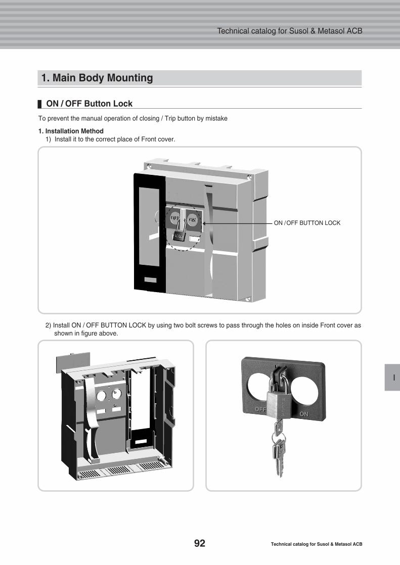
92 Technical catalog for Susol & Metasol ACB
Technical catalog for Susol & Metasol ACB
I
1. Main Body Mounting
To prevent the manual operation of closing / Trip button by mistake
1. Installation Method1) Install it to the correct place of Front cover.
ON / OFF Button Lock
2) Install ON / OFF BUTTON LOCK by using two bolt screws to pass through the holes on inside Front cover asshown in figure above.
ON /OFF BUTTON LOCK
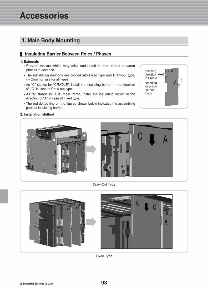
93
Accessories
I
1. Externals�Prevent the arc which may arise and result in short-circuit between
phases in advance
�The installation methods are divided into Fixed type and Draw-out type.(�Common use for all types)
�As “C” stands for “CRADLE”, install the insulating barrier in the direction of “C” in case of Draw-out type.
�As “A” stands for ACB main frame, install the insulating barrier in thedirection of “A” in case of Fixed type.
�The red dotted line on the figures shown below indicates the assemblingparts of insulating barrier.
2. Installation Method
Insulating Barrier Between Poles / Phases
Insertingdirectionto Cradle
Insertingdirection to mainbody
Draw-Out Type
Fixed Type
1. Main Body Mounting
�
�
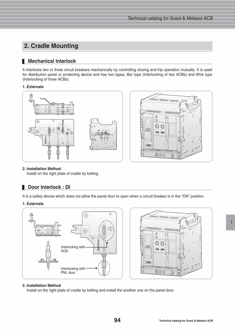
94 Technical catalog for Susol & Metasol ACB
Technical catalog for Susol & Metasol ACB
I
2. Cradle Mounting
It interlocks two or three circuit breakers mechanically by controlling closing and trip operation mutually. It is usedfor distribution panel or protecting device and has two types, Bar type (Interlocking of two ACBs) and Wire type(Interlocking of three ACBs)
1. Externals
2. Installation MethodInstall on the right plate of cradle by bolting.
Mechanical Interlock
It is a safety device which does not allow the panel door to open when a circuit breaker is in the “ON” position.
1. Externals
2. Installation MethodInstall on the right plate of cradle by bolting and install the another one on the panel door.
Door Interlock : DI
Interlocking withACB
Interlocking withPNL door
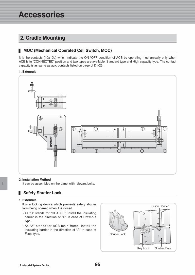
95
Accessories
I
2. Cradle Mounting
MOC (Mechanical Operated Cell Switch, MOC)
It is the contacts (10a10b) which indicate the ON / OFF condition of ACB by operating mechanically only whenACB is in “CONNECTED” position and two types are available, Standard type and High capacity type. The contactcapacity is as same as aux. contacts listed on page of D1-26.
1. Externals
2. Installation MethodIt can be assembled on the panel with relevant bolts.
1. ExternalsIt is a locking device which prevents safety shutterfrom being opened when it is closed.
�As “C” stands for “CRADLE”, install the insulating barrier in the direction of “C” in case of Draw-outtype.
�As “A” stands for ACB main frame, install theinsulating barrier in the direction of “A” in case ofFixed type.
Safety Shutter Lock
Guide Shutter
Shutter Lock
Key Lock Shutter Plate
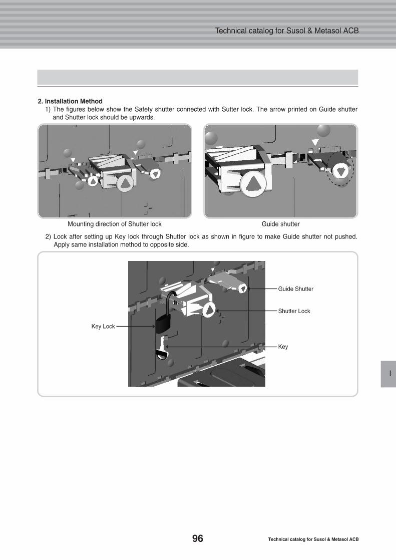
96 Technical catalog for Susol & Metasol ACB
Technical catalog for Susol & Metasol ACB
I
2. Installation Method1) The figures below show the Safety shutter connected with Sutter lock. The arrow printed on Guide shutter
and Shutter lock should be upwards.
Mounting direction of Shutter lock Guide shutter
2) Lock after setting up Key lock through Shutter lock as shown in figure to make Guide shutter not pushed.Apply same installation method to opposite side.
Guide Shutter
Shutter Lock
Key
Key Lock
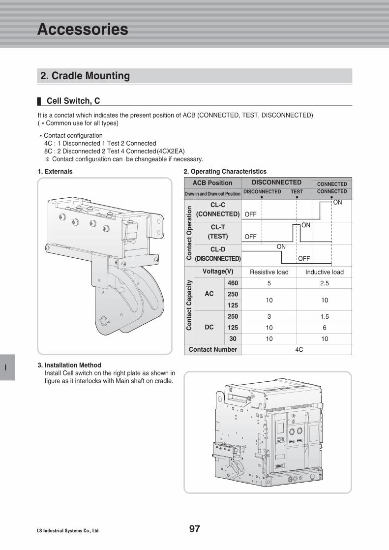
97
I
Accessories
It is a conctat which indicates the present position of ACB (CONNECTED, TEST, DISCONNECTED)(�Common use for all types)
�Contact configuration4C : 1 Disconnected 1 Test 2 Connected8C : 2 Disconnected 2 Test 4 Connected(4CX2EA)※ Contact configuration can be changeable if necessary.
1. Externals 2. Operating Characteristics
3. Installation MethodInstall Cell switch on the right plate as shown infigure as it interlocks with Main shaft on cradle.
Cell Switch, C
ACB Position
Draw-in and Draw-out Position
DISCONNECTEDC
onta
ctO
pera
tion
Con
tact
Cap
acity
CL-C(CONNECTED)
CL-T(TEST)
CL-D(DISCONNECTED)
Voltage(V)
AC
460
250
125
250
125
30
DC
Contact Number 4C
DISCONNECTEDCONNECTEDCONNECTEDTEST
Resistive load
5
10
3
10
10
OFF
OFF
OFF
ON
ON
ON
Inductive load
2.5
10
1.5
6
10
2. Cradle Mounting
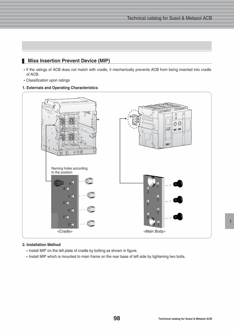
98 Technical catalog for Susol & Metasol ACB
Technical catalog for Susol & Metasol ACB
I
2. Installation Method
�Install MIP on the left plate of cradle by bolting as shown in figure.
�Install MIP which is mounted to main frame on the rear base of left side by tightening two bolts.
�If the ratings of ACB does not match with cradle, it mechanically prevents ACB from being inserted into cradleof ACB.
�Classification upon ratings
1. Externals and Operating Characteristics
Miss Insertion Prevent Device (MIP)
Naming holes accordingto the position
<Cradle>
A
B
C
D
E
F
G
12
34
5
7
6
<Main Body>
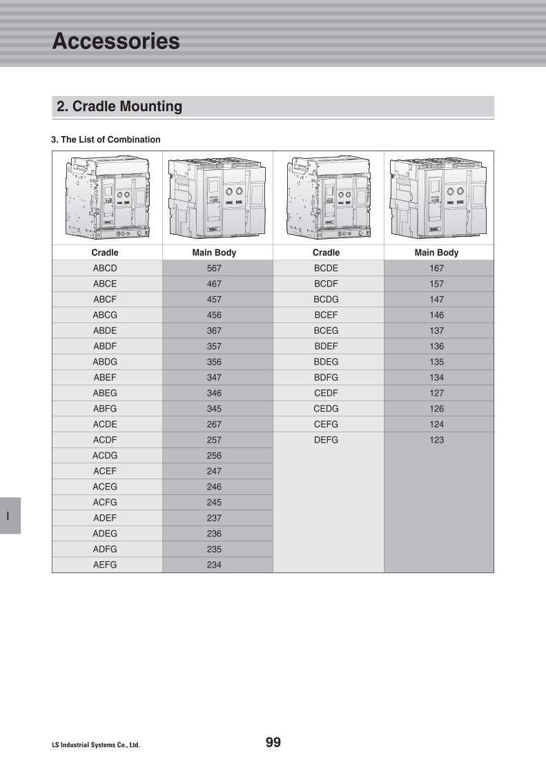
99
I
Accessories
3. The List of Combination
Cradle Main Body Cradle Main Body
ABCD 567 BCDE 167
ABCE 467 BCDF 157
ABCF 457 BCDG 147
ABCG 456 BCEF 146
ABDE 367 BCEG 137
ABDF 357 BDEF 136
ABDG 356 BDEG 135
ABEF 347 BDFG 134
ABEG 346 CEDF 127
ABFG 345 CEDG 126
ACDE 267 CEFG 124
ACDF 257 DEFG 123
ACDG 256
ACEF 247
ACEG 246
ACFG 245
ADEF 237
ADEG 236
ADFG 235
AEFG 234
2. Cradle Mounting
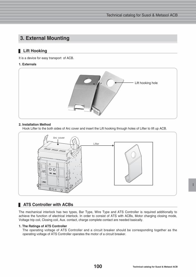
100 Technical catalog for Susol & Metasol ACB
Technical catalog for Susol & Metasol ACB
I
3. External Mounting
It is a device for easy transport of ACB.
1. Externals
Lift Hooking
2. Installation MethodHook Lifter to the both sides of Arc cover and insert the Lift hooking through holes of Lifter to lift up ACB.
Lift hooking hole
The mechanical interlock has two types, Bar Type, Wire Type and ATS Controller is required additionally toachieve the function of electrical interlock. In order to consist of ATS with ACBs, Motor charging closing mode,Voltage trip coil, Closing coil, Aux. contact, charge complete contact are needed basically.
1. The Ratings of ATS ControllerThe operating voltage of ATS Controller and a circuit breaker should be corresponding together as the operating voltage of ATS Controller operates the motor of a circuit breaker.
ATS Controller with ACBs
Arc cover
Lifter
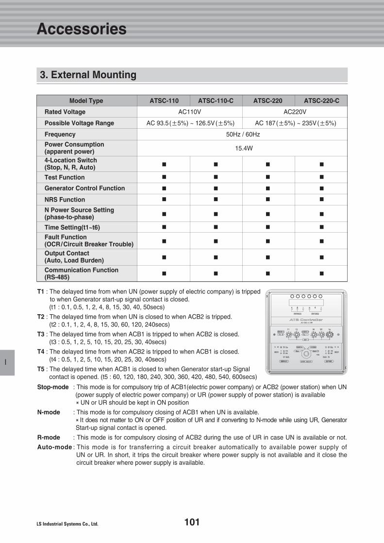
101
Accessories
I
Model Type ATSC-110 ATSC-110-C ATSC-220 ATSC-220-C
Rated Voltage AC110V AC220V
Possible Voltage Range AC 93.5(±5%) ~ 126.5V(±5%) AC 187(±5%) ~ 235V(±5%)
Frequency 50Hz / 60Hz
Power Consumption15.4W(apparent power)
4-Location Switch■ ■ ■ ■(Stop, N, R, Auto)
Test Function ■ ■ ■ ■
Generator Control Function ■ ■ ■ ■
NRS Function ■ ■ ■ ■
N Power Source Setting■ ■ ■ ■(phase-to-phase)
Time Setting(t1~t6) ■ ■ ■ ■
Fault Function■ ■ ■ ■(OCR/Circuit Breaker Trouble)
Output Contact■ ■ ■ ■(Auto, Load Burden)
Communication Function ■ ■ ■ ■(RS-485)
T1 : The delayed time from when UN (power supply of electric company) is tripped to when Generator start-up signal contact is closed. (t1 : 0.1, 0.5, 1, 2, 4, 8, 15, 30, 40, 50secs)
T2 : The delayed time from when UN is closed to when ACB2 is tripped. (t2 : 0.1, 1, 2, 4, 8, 15, 30, 60, 120, 240secs)
T3 : The delayed time from when ACB1 is tripped to when ACB2 is closed. (t3 : 0.5, 1, 2, 5, 10, 15, 20, 25, 30, 40secs)
T4 : The delayed time from when ACB2 is tripped to when ACB1 is closed. (t4 : 0.5, 1, 2, 5, 10, 15, 20, 25, 30, 40secs)
T5 : The delayed time when ACB1 is closed to when Generator start-up Signalcontact is opened. (t5 : 60, 120, 180, 240, 300, 360, 420, 480, 540, 600secs)
Stop-mode : This mode is for compulsory trip of ACB1(electric power company) or ACB2 (power station) when UN(power supply of electric power company) or UR (power supply of power station) is available �UN or UR should be kept in ON position
N-mode : This mode is for compulsory closing of ACB1 when UN is available. �It does not matter to ON or OFF position of UR and if converting to N-mode while using UR, Generator Start-up signal contact is opened.
R-mode : This mode is for compulsory closing of ACB2 during the use of UR in case UN is available or not.
Auto-mode : This mode is for transferring a circuit breaker automatically to available power supply of UN or UR. In short, it trips the circuit breaker where power supply is not available and it close thecircuit breaker where power supply is available.
3. External Mounting
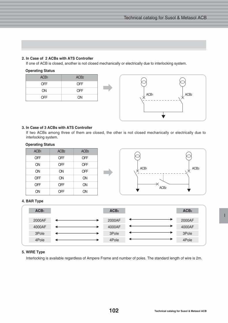
102 Technical catalog for Susol & Metasol ACB
Technical catalog for Susol & Metasol ACB
I
2. In Case of 2 ACBs with ATS ControllerIf one of ACB is closed, another is not closed mechanically or electrically due to interlocking system.
Operating Status
ACB1 ACB2
OFF OFF
ON OFF
OFF ON
3. In Case of 3 ACBs with ATS ControllerIf two ACBs among three of them are closed, the other is not closed mechanically or electrically due tointerlocking system.
Operating Status
5. WIRE Type
Interlocking is available regardless of Ampere Frame and number of poles. The standard length of wire is 2m.
4. BAR Type
ACB1 ACB2 ACB3
OFF OFF OFF
ON OFF OFF
ON ON OFF
OFF ON ON
OFF OFF ON
ON OFF ON
ACB1 ACB2 ACB3
2000AF 2000AF 2000AF
4000AF 4000AF 4000AF
3Pole 3Pole 3Pole
4Pole 4Pole 4Pole
ACB1
ACB1
ACB2
ACB3
ACB2
�
�
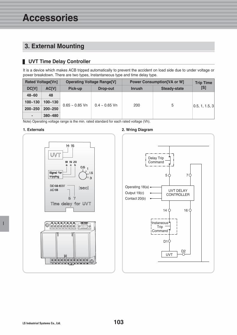
103
Accessories
I
It is a device which makes ACB tripped automatically to prevent the accident on load side due to under voltage orpower breakdown. There are two types, Instantaneous type and time delay type.
1. Externals 2. Wring Diagram
Note) Operating voltage range is the min. rated standard for each rated voltage (Vh).
Rated Voltage[Vn] Operating Voltage Range[V] Power Consumption[VA or W]
Pick-up Drop-out Inrush Steady-state
0.65 ~ 0.85 Vn 0.4 ~ 0.65 Vn 200 5
DC[V] AC[V]
48~60 48
100~130 100~130
200~250 200~250
- 380~480
Trip Time[S]
0.5, 1, 1.5, 3
UVT Time Delay Controller
UVT DELAYCONTROLLER
UVT
Delay TripCommand
InstaneousTrip
Command
Operating 18(a)
Output 19(c)
Contact 20(b)
5 7
14
D1
D2
16
3. External Mounting
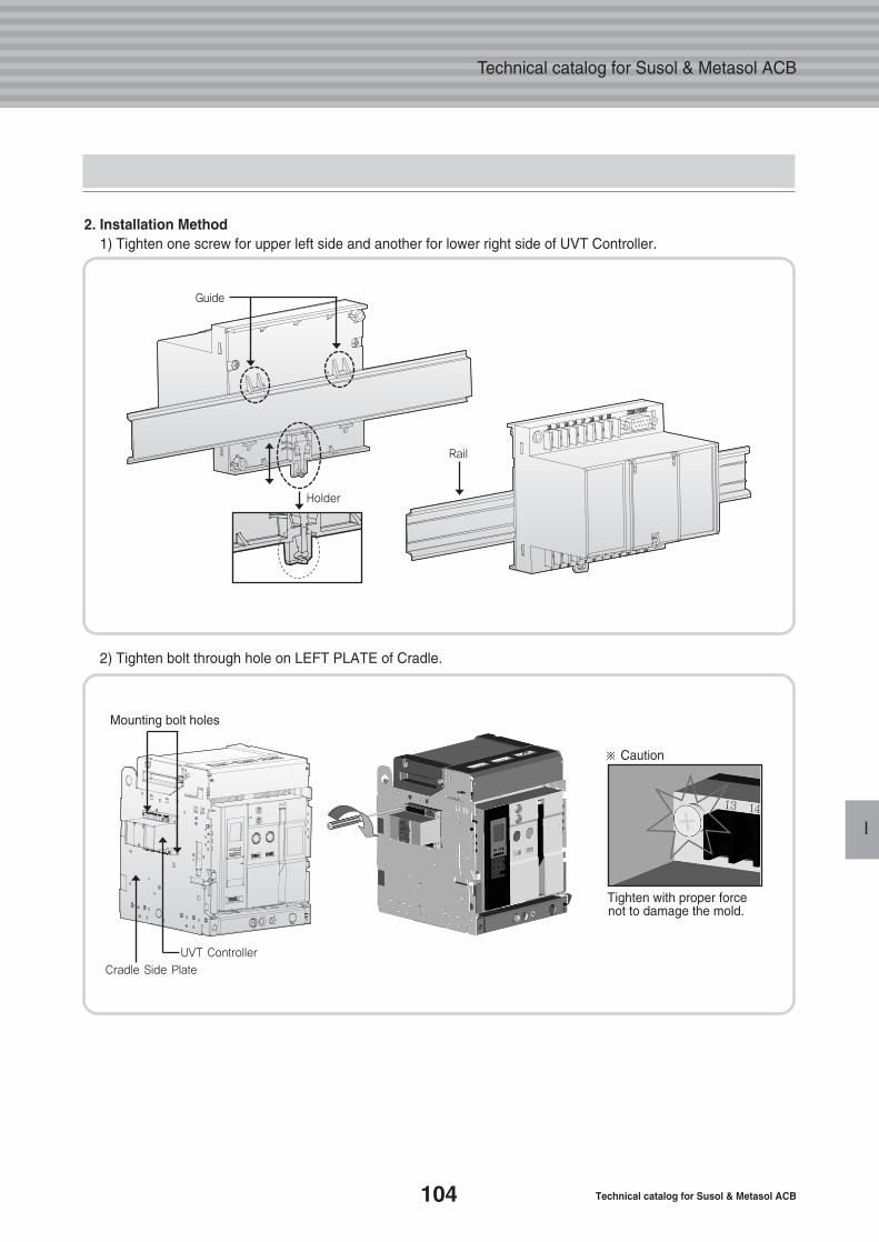
104 Technical catalog for Susol & Metasol ACB
Technical catalog for Susol & Metasol ACB
I
2. Installation Method1) Tighten one screw for upper left side and another for lower right side of UVT Controller.
2) Tighten bolt through hole on LEFT PLATE of Cradle.
Mounting bolt holes
Tighten with proper forcenot to damage the mold.
※ Caution
Guide
Holder
Rail
UVT Controller
Cradle Side Plate
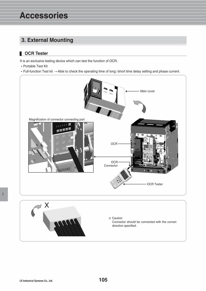
105
Accessories
I
It is an exclusive testing device which can test the function of OCR.
�Portable Test Kit
�Full-function Test kit � Able to check the operating time of long /short time delay setting and phase current.
OCR Tester
Main cover
※ CautionConnector should be connected with the correctdirection specified.
X
OCR
OCRConnector
OCR Tester
Magnification of connector connecting part
3. External Mounting
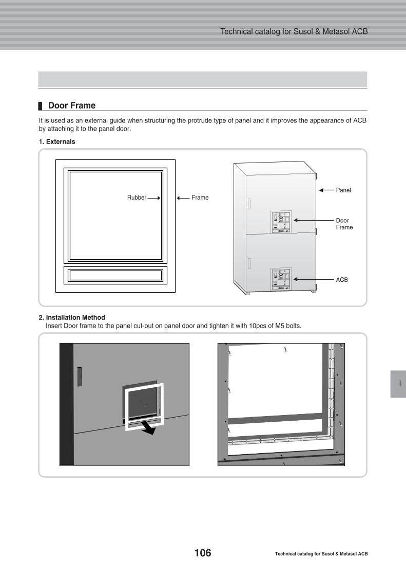
106 Technical catalog for Susol & Metasol ACB
Technical catalog for Susol & Metasol ACB
I
Rubber FramePanel
DoorFrame
ACB
It is used as an external guide when structuring the protrude type of panel and it improves the appearance of ACB by attaching it to the panel door.
1. Externals
2. Installation MethodInsert Door frame to the panel cut-out on panel door and tighten it with 10pcs of M5 bolts.
Door Frame
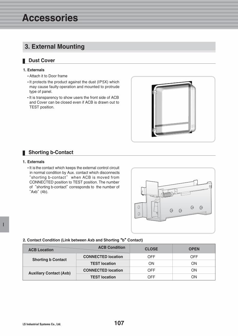
107
I
1. Externals
�Attach it to Door frame
�It protects the product against the dust (IP5X) whichmay cause faulty operation and mounted to protrudetype of panel.
�It is transparency to show users the front side of ACBand Cover can be closed even if ACB is drawn out toTEST position.
Dust Cover
1. Externals
�It is the contact which keeps the external control circuitin normal condition by Aux. contact which disconnects
“shorting b-contact” when ACB is moved fromCONNECTED position to TEST position. The number of “shorting b-contact”corresponds to the number of
“Axb”(4b).
2. Contact Condition (Link between Axb and Shorting ““b””Contact)
Shorting b-Contact
ACB LocationACB Condition CLOSE
OFF
ON
OFF
OFF
OPEN
OFF
ON
ON
ON
Shorting b ContactCONNECTED location
TEST location
CONNECTED location
TEST locationAuxiliary Contact (Axb)
3. External Mounting
Accessories
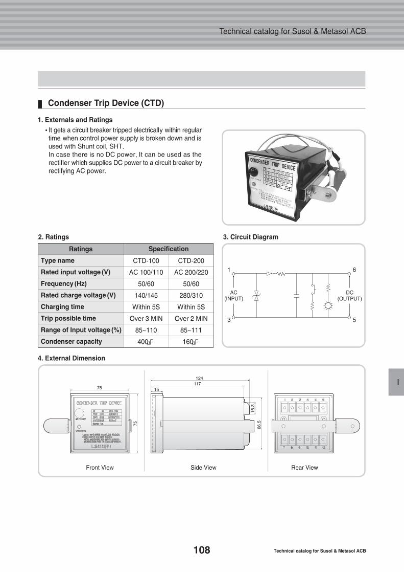
108 Technical catalog for Susol & Metasol ACB
Technical catalog for Susol & Metasol ACB
I
1. Externals and Ratings
�It gets a circuit breaker tripped electrically within regulartime when control power supply is broken down and isused with Shunt coil, SHT. In case there is no DC power, It can be used as therectifier which supplies DC power to a circuit breaker byrectifying AC power.
2. Ratings 3. Circuit Diagram
Condenser Trip Device (CTD)
Ratings Specification
CTD-100
AC 100/110
50/60
140/145
Within 5S
Over 3 MIN
85~110
400㎌
CTD-200
AC 200/220
50/60
280/310
Within 5S
Over 2 MIN
85~111
160㎌
Type name
Rated input voltage (V)
Frequency (Hz)
Rated charge voltage (V)
Charging time
Trip possible time
Range of Input voltage (%)
Condenser capacity
4. External Dimension
Front View Side View Rear View
AC(INPUT)
1 6
3 5
DC(OUTPUT)
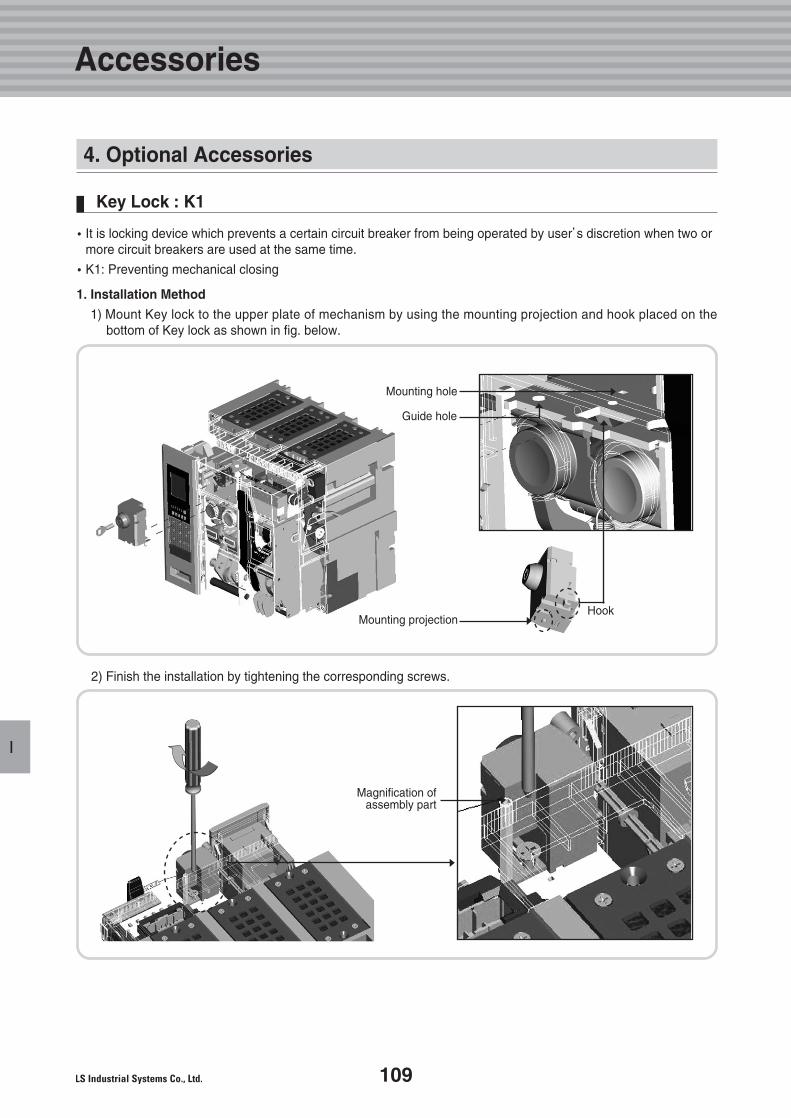
109
I
4. Optional Accessories
Key Lock : K1
�It is locking device which prevents a certain circuit breaker from being operated by user’s discretion when two ormore circuit breakers are used at the same time.
�K1: Preventing mechanical closing
1. Installation Method
1) Mount Key lock to the upper plate of mechanism by using the mounting projection and hook placed on thebottom of Key lock as shown in fig. below.
2) Finish the installation by tightening the corresponding screws.
Magnification of assembly part
Mounting projectionHook
Guide hole
Mounting hole
Accessories
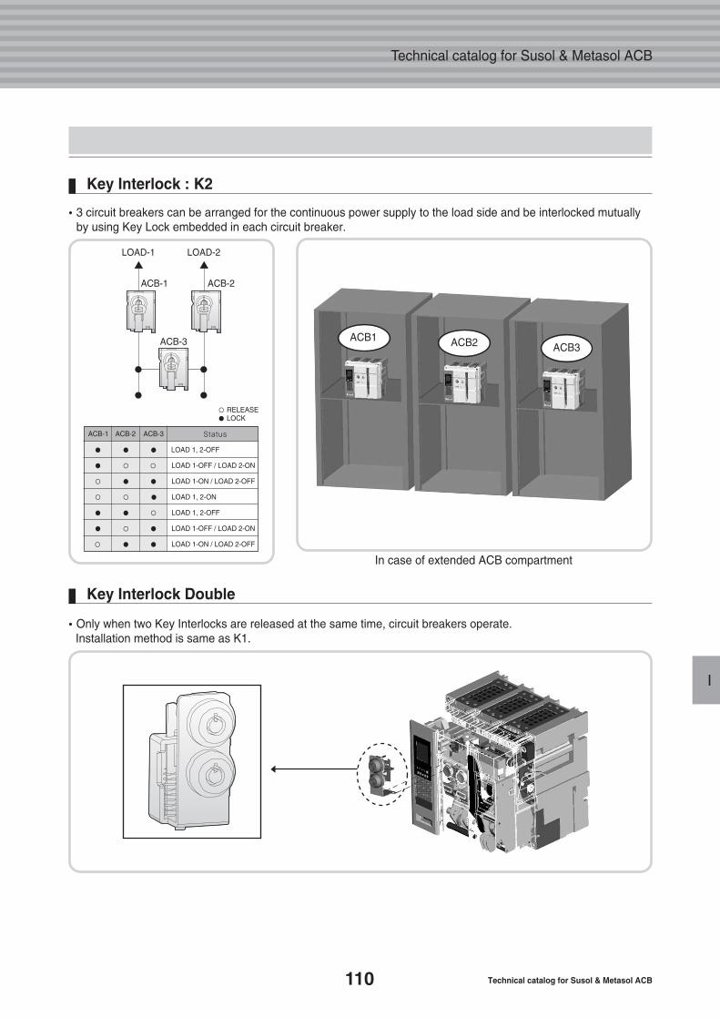
110 Technical catalog for Susol & Metasol ACB
Technical catalog for Susol & Metasol ACB
I
�3 circuit breakers can be arranged for the continuous power supply to the load side and be interlocked mutuallyby using Key Lock embedded in each circuit breaker.
In case of extended ACB compartment
Key Interlock : K2
�Only when two Key Interlocks are released at the same time, circuit breakers operate. Installation method is same as K1.
Key Interlock Double
LOAD-1
ACB-1 ACB-2
ACB-3
LOAD-2
ACB-1 ACB-2 ACB-3 Status
● ● ● LOAD 1, 2-OFF
● ○ ○ LOAD 1-OFF / LOAD 2-ON
○ ● ● LOAD 1-ON / LOAD 2-OFF
○ ○ ● LOAD 1, 2-ON
● ● ○ LOAD 1, 2-OFF
● ○ ● LOAD 1-OFF / LOAD 2-ON
○ ● ● LOAD 1-ON / LOAD 2-OFF
○ RELEASE● LOCK
ACB1 ACB2 ACB3
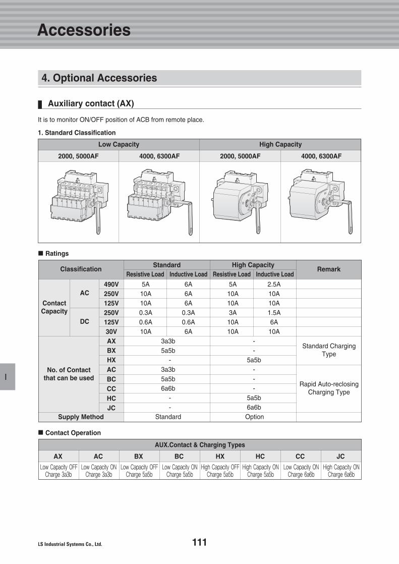
111
I
It is to monitor ON/OFF position of ACB from remote place.
1. Standard Classification
High CapacityLow Capacity
2000, 5000AF 4000, 6300AF 2000, 5000AF 4000, 6300AF
Auxiliary contact (AX)
4. Optional Accessories
Accessories
Ratings
Classification
ContactCapacity
No. of Contactthat can be used
AC490V250V125V250V125V30VAXBXHXACBCCCHCJC
DC
Standard ChargingType
Rapid Auto-reclosingCharging Type
Supply Method
AUX.Contact & Charging Types
AX AC BX BC HX HC CC JC
RemarkHigh CapacityStandard
Inductive LoadResistive Load Inductive LoadResistive Load
3a3b -5a5b -
- 5a5b3a3b -5a5b -6a6b -
- 5a5b- 6a6b
Standard Option
5A 6A 5A 2.5A10A 6A 10A 10A10A 6A 10A 10A0.3A 0.3A 3A 1.5A0.6A 0.6A 10A 6A10A 6A 10A 10A
Contact Operation
Low Capacity OFFCharge 3a3b
Low Capacity ONCharge 3a3b
Low Capacity OFFCharge 5a5b
Low Capacity ONCharge 5a5b
High Capacity OFFCharge 5a5b
High Capacity ONCharge 5a5b
Low Capacity ONCharge 6a6b
High Capacity ONCharge 6a6b
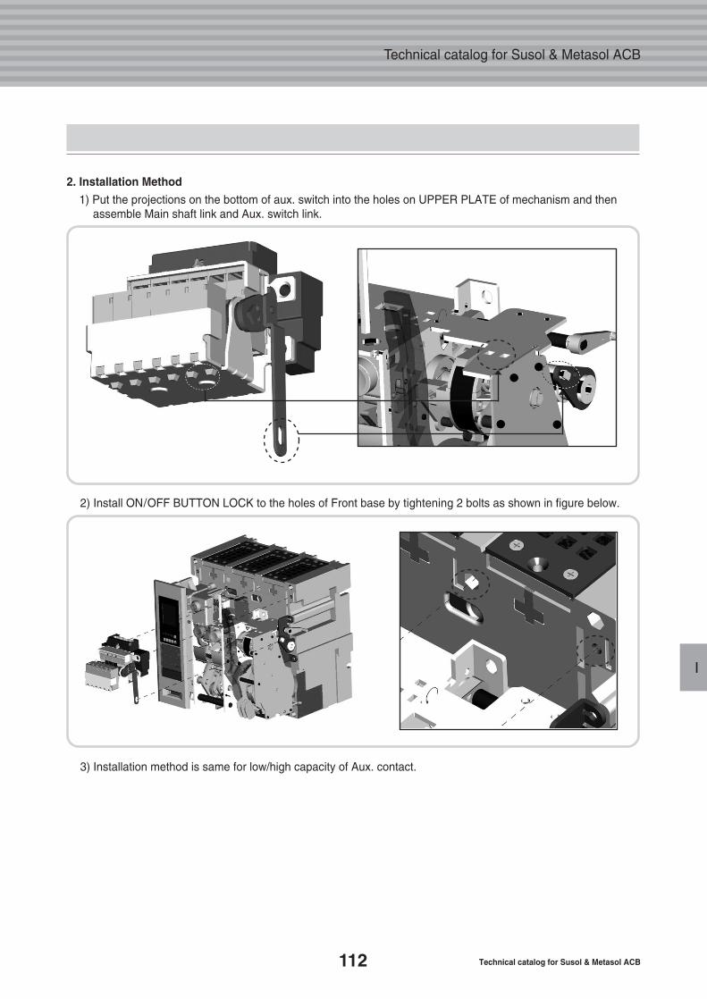
112 Technical catalog for Susol & Metasol ACB
Technical catalog for Susol & Metasol ACB
I
2. Installation Method
1) Put the projections on the bottom of aux. switch into the holes on UPPER PLATE of mechanism and thenassemble Main shaft link and Aux. switch link.
2) Install ON/OFF BUTTON LOCK to the holes of Front base by tightening 2 bolts as shown in figure below.
3) Installation method is same for low/high capacity of Aux. contact.
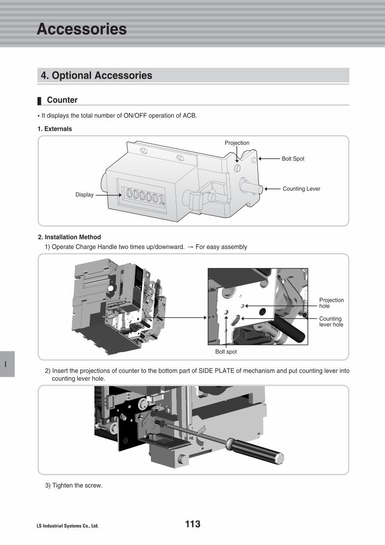
113
I
�It displays the total number of ON/OFF operation of ACB.
1. Externals
Counter
Display
2. Installation Method
1) Operate Charge Handle two times up/downward. � For easy assembly
2) Insert the projections of counter to the bottom part of SIDE PLATE of mechanism and put counting lever intocounting lever hole.
3) Tighten the screw.
Projection hole
Countinglever hole
Bolt spot
Projection
Bolt Spot
Counting Lever
4. Optional Accessories
Accessories
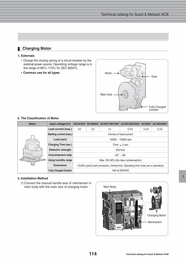
114 Technical catalog for Susol & Metasol ACB
Technical catalog for Susol & Metasol ACB
I
1. Externals
�Charge the closing spring of a circuit breaker by theexternal power source. Operating voltage range is inthe range of 85%~110% Vn (IEC 60947).
��Common use for all types
Charging Motor
Motor
2. The Classification of Motor
3. Installation Method
1) Connect the manual handle axis of mechanism inmain body with the main axis of charging motor.
Main Axis
Gear
Fully ChargedContact
Main Body
Charging Motor
Mechanism
Input voltage(Vn)
Load current (max.)
Starting current (max.)
Load (rpm)
Charging Time (sec.)
Dielectric strength
Using temperature range
Using humidity range
Endurance
Fully Charged Contact
5 times of load current
15000 ~ 19000 rpm
Time 5 sec
2kV/min
-20。~ 60。
Max. RH 80%(No dew condensation)
15,000 cycle(Load connection, 2 times/min, Operating time:5sec per a operation)
10A at 250VAC
Motor DC24/30V DC48/60V AC380V AC440/480VAC/DC100/130V AC/DC200/250V
5A 3A 0.3A 0.3A1A 0.5A
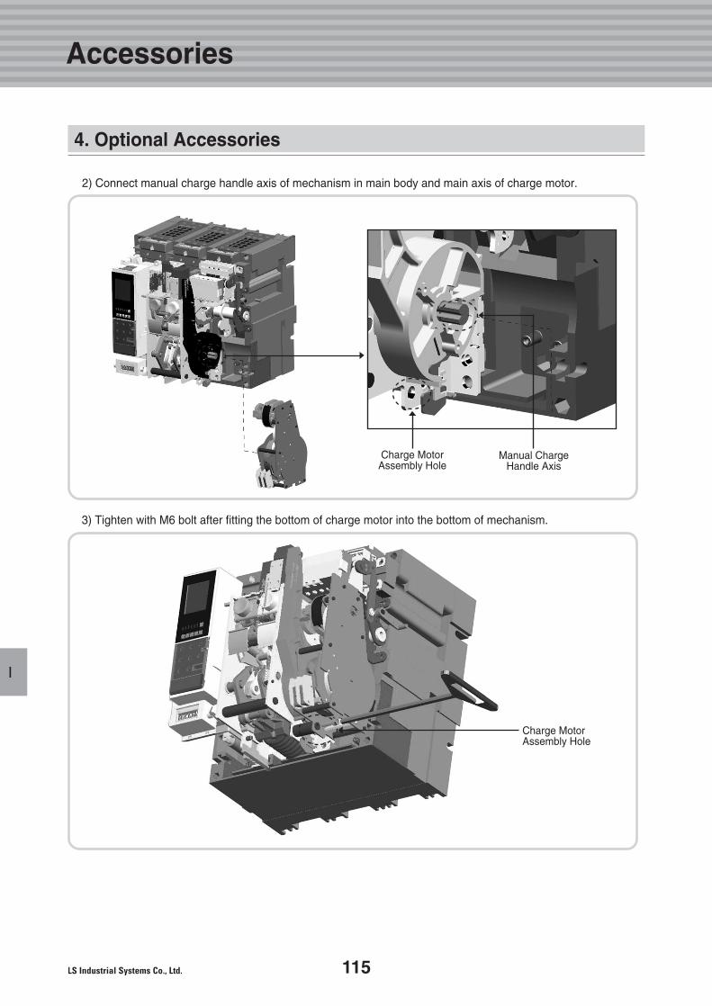
115
I
2) Connect manual charge handle axis of mechanism in main body and main axis of charge motor.
Manual Charge Handle Axis
Charge Motor Assembly Hole
3) Tighten with M6 bolt after fitting the bottom of charge motor into the bottom of mechanism.
Charge Motor Assembly Hole
4. Optional Accessories
Accessories
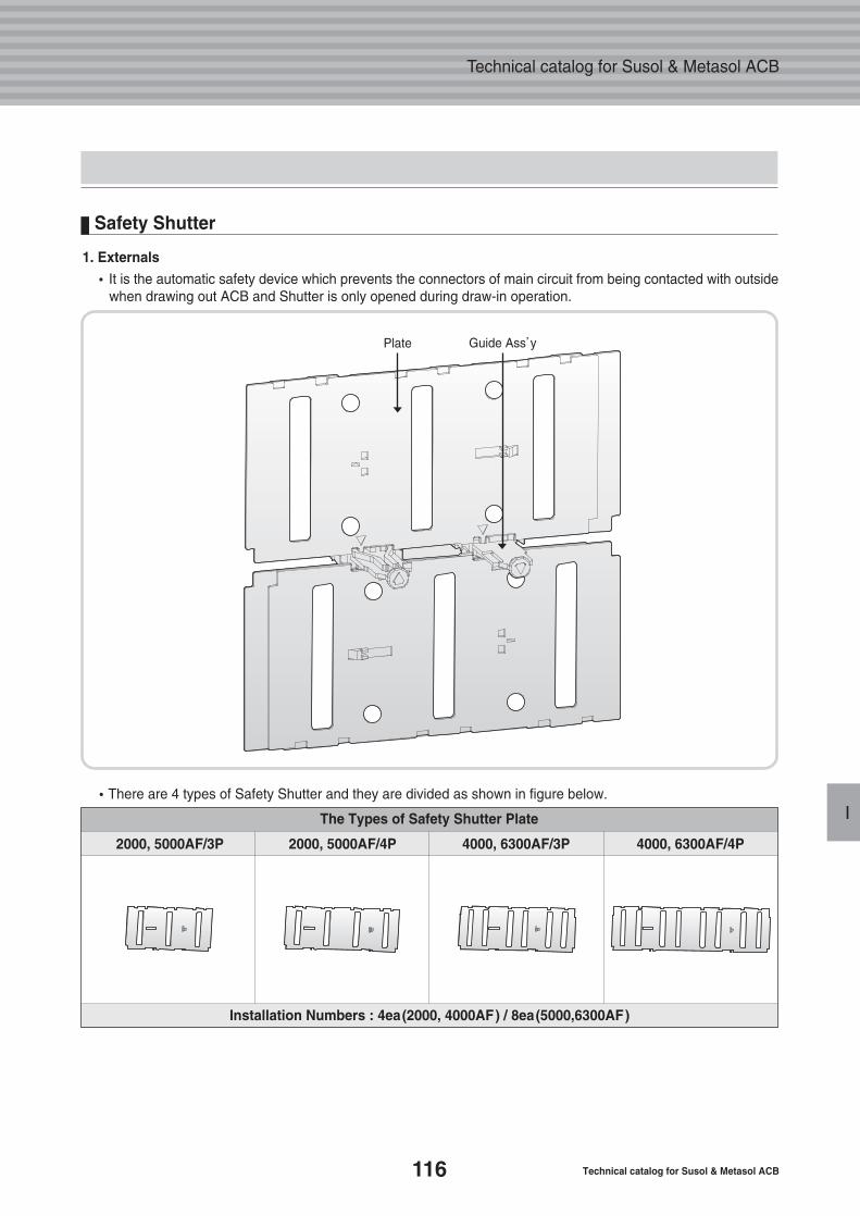
116 Technical catalog for Susol & Metasol ACB
Technical catalog for Susol & Metasol ACB
I
1. Externals
�It is the automatic safety device which prevents the connectors of main circuit from being contacted with outsidewhen drawing out ACB and Shutter is only opened during draw-in operation.
�There are 4 types of Safety Shutter and they are divided as shown in figure below.
The Types of Safety Shutter Plate
2000, 5000AF/3P 2000, 5000AF/4P 4000, 6300AF/3P 4000, 6300AF/4P
Installation Numbers : 4ea(2000, 4000AF) / 8ea(5000,6300AF)
Safety Shutter
Plate Guide Ass’y
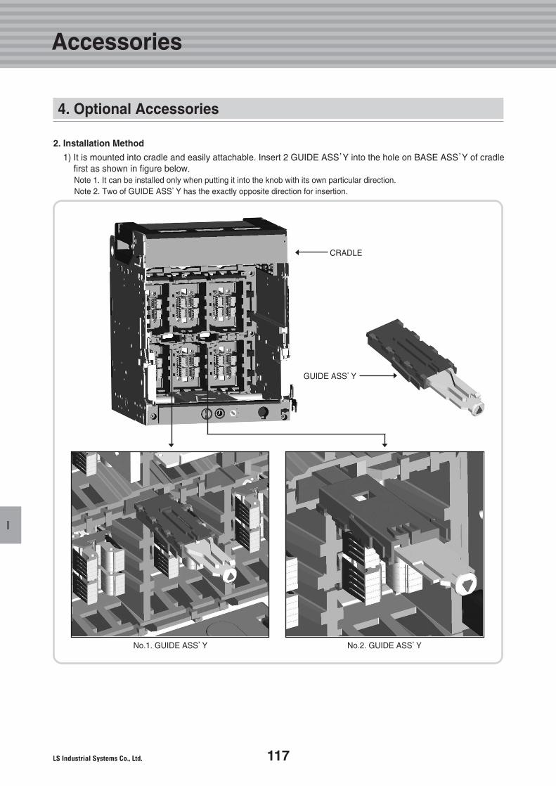
117
I
2. Installation Method
1) It is mounted into cradle and easily attachable. Insert 2 GUIDE ASS’Y into the hole on BASE ASS’Y of cradlefirst as shown in figure below. Note 1. It can be installed only when putting it into the knob with its own particular direction.Note 2. Two of GUIDE ASS’Y has the exactly opposite direction for insertion.
CRADLE
No.1. GUIDE ASS’Y No.2. GUIDE ASS’Y
GUIDE ASS’Y
4. Optional Accessories
Accessories
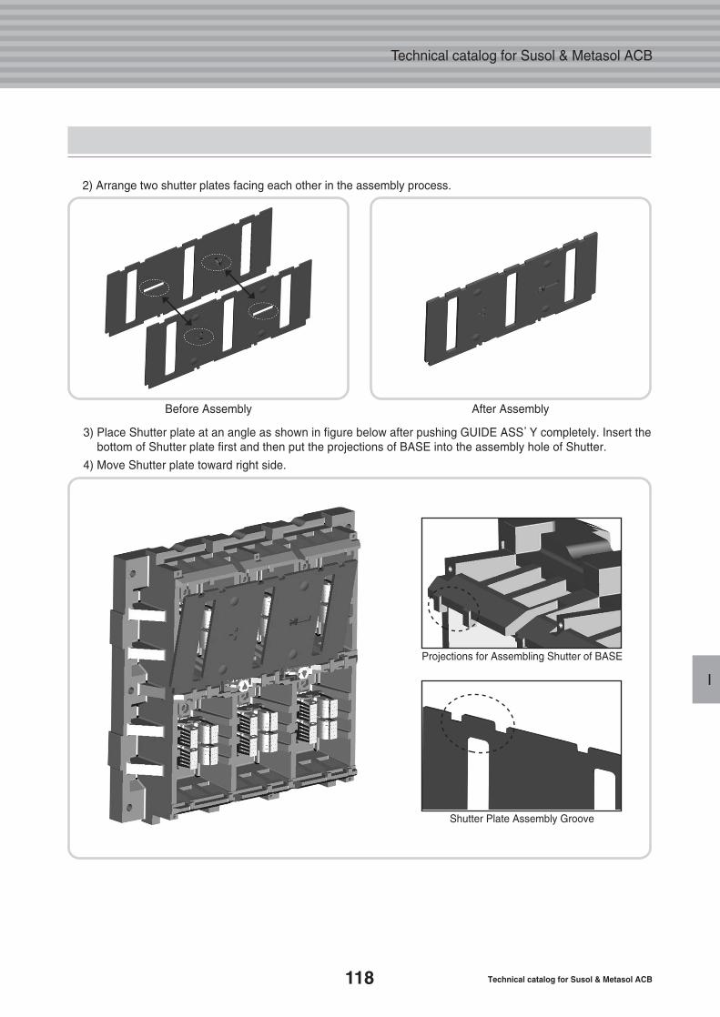
118 Technical catalog for Susol & Metasol ACB
Technical catalog for Susol & Metasol ACB
I
2) Arrange two shutter plates facing each other in the assembly process.
3) Place Shutter plate at an angle as shown in figure below after pushing GUIDE ASS’Y completely. Insert thebottom of Shutter plate first and then put the projections of BASE into the assembly hole of Shutter.
4) Move Shutter plate toward right side.
Before Assembly After Assembly
Projections for Assembling Shutter of BASE
Shutter Plate Assembly Groove
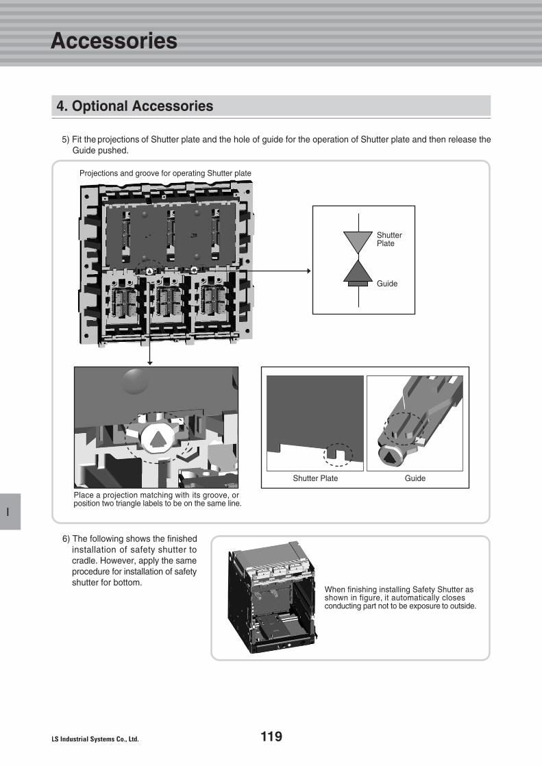
119
I
5) Fit the projections of Shutter plate and the hole of guide for the operation of Shutter plate and then release theGuide pushed.
6) The following shows the finishedinstallation of safety shutter tocradle. However, apply the sameprocedure for installation of safetyshutter for bottom.
Shutter Plate
Projections and groove for operating Shutter plate
Place a projection matching with its groove, orposition two triangle labels to be on the same line.
When finishing installing Safety Shutter asshown in figure, it automatically closesconducting part not to be exposure to outside.
ShutterPlate
Guide
Guide
4. Optional Accessories
Accessories
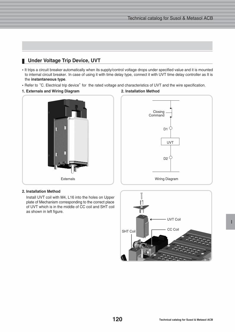
120 Technical catalog for Susol & Metasol ACB
Technical catalog for Susol & Metasol ACB
I
�It trips a circuit breaker automatically when its supply/control voltage drops under specified value and it is mountedto internal circuit breaker. In case of using it with time delay type, connect it with UVT time delay controller as It isthe instantaneous type.
�Refer to “C. Electrical trip device”for the rated voltage and characteristics of UVT and the wire specification.
1. Externals and Wiring Diagram 2. Installation Method
2. Installation Method
Install UVT coil with M4, L16 into the holes on Upperplate of Mechanism corresponding to the correct placeof UVT which is in the middle of CC coil and SHT coilas shown in left figure.
Under Voltage Trip Device, UVT
CC Coil
UVT Coil
ClosingCommand
D1
D2
UVT
Externals Wiring Diagram
SHT Coil
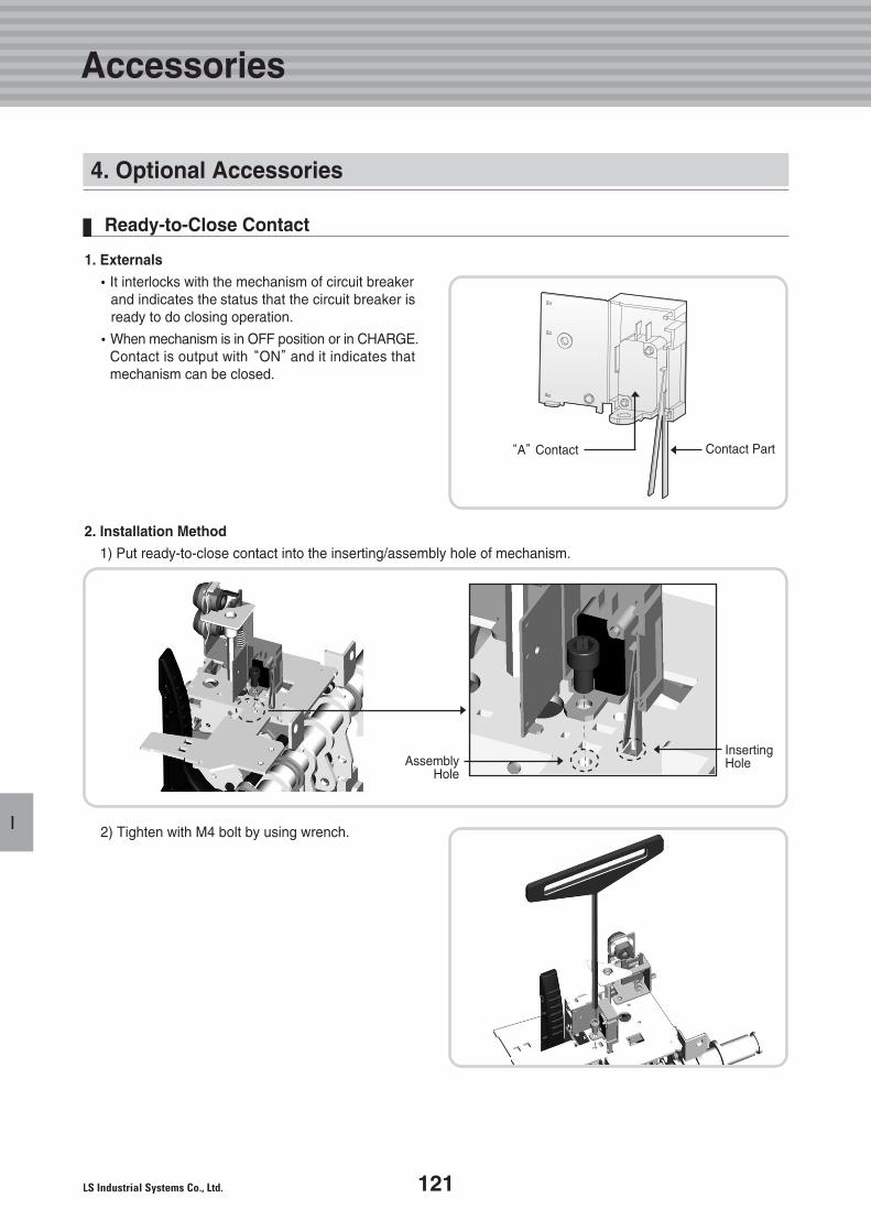
121
I
1. Externals
�It interlocks with the mechanism of circuit breakerand indicates the status that the circuit breaker isready to do closing operation.
�When mechanism is in OFF position or in CHARGE.Contact is output with “ON”and it indicates thatmechanism can be closed.
2. Installation Method
1) Put ready-to-close contact into the inserting/assembly hole of mechanism.
Ready-to-Close Contact
2) Tighten with M4 bolt by using wrench.
“A”Contact
AssemblyHole
InsertingHole
Contact Part
4. Optional Accessories
Accessories
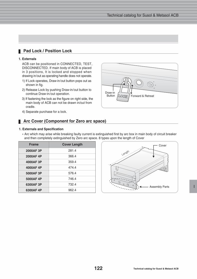
122 Technical catalog for Susol & Metasol ACB
Technical catalog for Susol & Metasol ACB
I
1. Externals
ACB can be positioned in CONNECTED, TEST,DISCONNECTED. If main body of ACB is placedin 3 positions, It is locked and stopped whendrawing in/out as operating handle does not operate.
1) If Lock operates, Draw-in/out button pops out asshown in fig.
2) Release Lock by pushing Draw-in/out button to continue Draw-in/out operation.
3) If fastening the lock as the figure on right side, themain body of ACB can not be drawn in/out fromcradle.
4) Separate purchase for a lock.
Pad Lock / Position Lock
Draw-inButton Forward & Retreat
1. Externals and Specification
�Arc which may arise while breaking faulty current is extinguished first by arc box in main body of circuit breakerand then completely extinguished by Zero arc space. 8 types upon the length of Cover
2000AF 3P
2000AF 4P
4000AF 3P
4000AF 4P
5000AF 3P
5000AF 4P
6300AF 3P
6300AF 4P
281.4
366.4
359.4
474.4
576.4
746.4
732.4
962.4
Arc Cover (Component for Zero arc space)
Assembly Parts
CoverFrame Cover Length
Leng
th
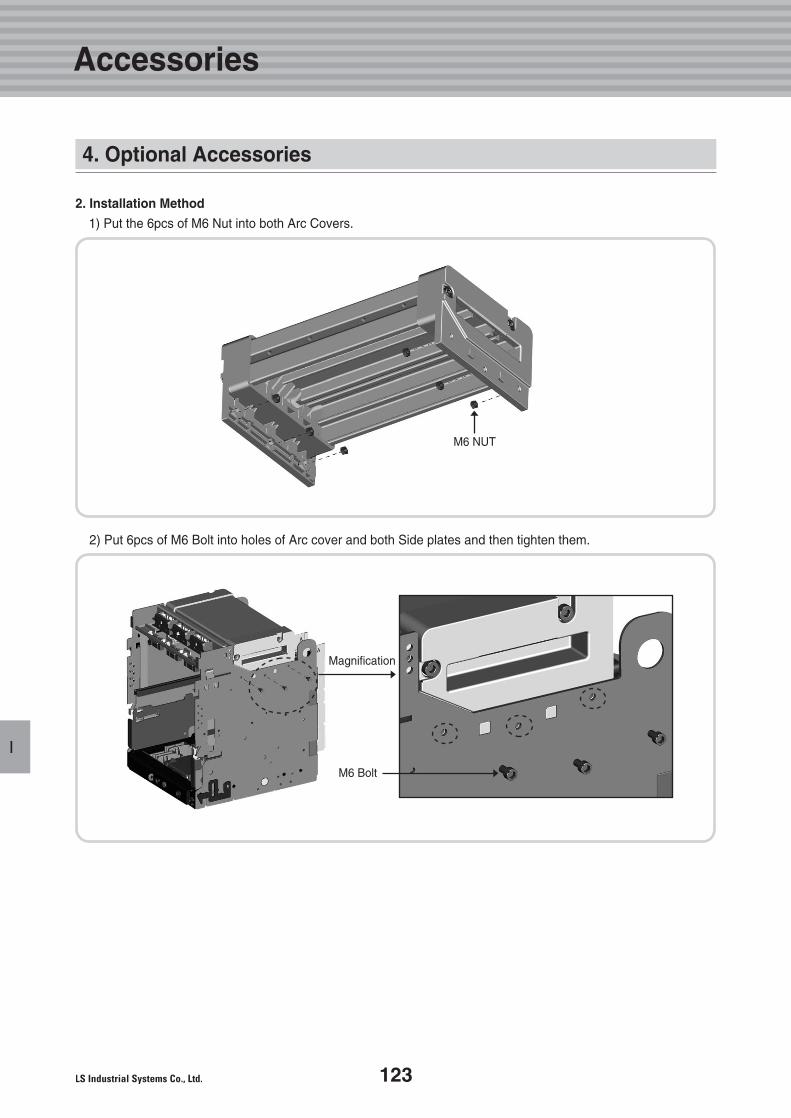
123
I
2. Installation Method
1) Put the 6pcs of M6 Nut into both Arc Covers.
2) Put 6pcs of M6 Bolt into holes of Arc cover and both Side plates and then tighten them.
M6 NUT
Magnification
M6 Bolt
4. Optional Accessories
Accessories
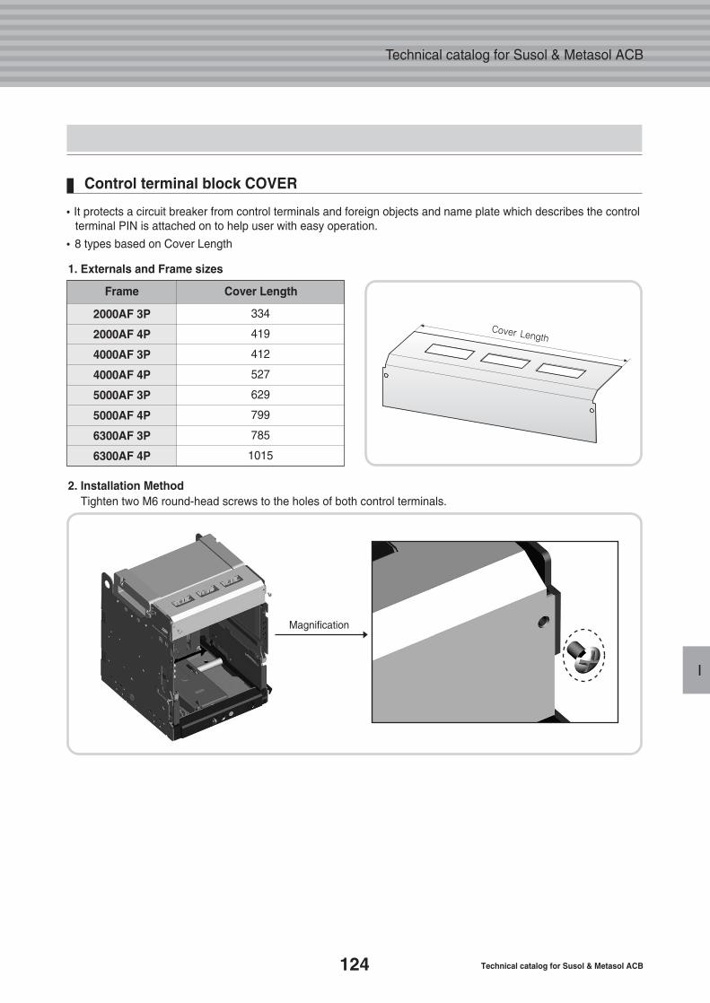
124 Technical catalog for Susol & Metasol ACB
Technical catalog for Susol & Metasol ACB
I
Magnification
2. Installation MethodTighten two M6 round-head screws to the holes of both control terminals.
1. Externals and Frame sizes
�It protects a circuit breaker from control terminals and foreign objects and name plate which describes the control terminal PIN is attached on to help user with easy operation.
�8 types based on Cover Length
Control terminal block COVER
2000AF 3P
2000AF 4P
4000AF 3P
4000AF 4P
5000AF 3P
5000AF 4P
6300AF 3P
6300AF 4P
334
419
412
527
629
799
785
1015
Frame Cover Length
Cover Length
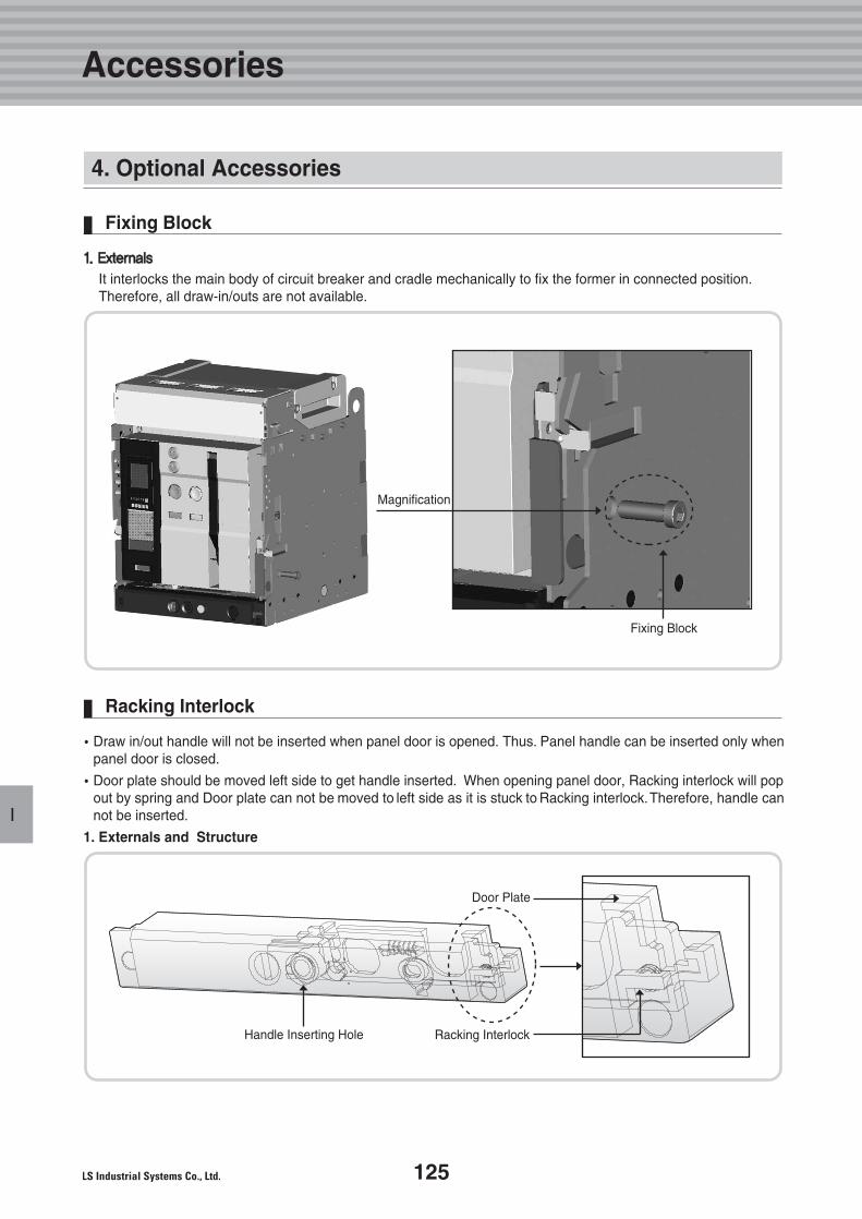
125
I
11.. EExxtteerrnnaallss
It interlocks the main body of circuit breaker and cradle mechanically to fix the former in connected position.Therefore, all draw-in/outs are not available.
Fixing Block
�Draw in/out handle will not be inserted when panel door is opened. Thus. Panel handle can be inserted only whenpanel door is closed.
�Door plate should be moved left side to get handle inserted. When opening panel door, Racking interlock will popout by spring and Door plate can not be moved to left side as it is stuck to Racking interlock.Therefore, handle cannot be inserted.
1. Externals and Structure
Racking Interlock
Fixing Block
Door Plate
Racking InterlockHandle Inserting Hole
4. Optional Accessories
Accessories
Magnification
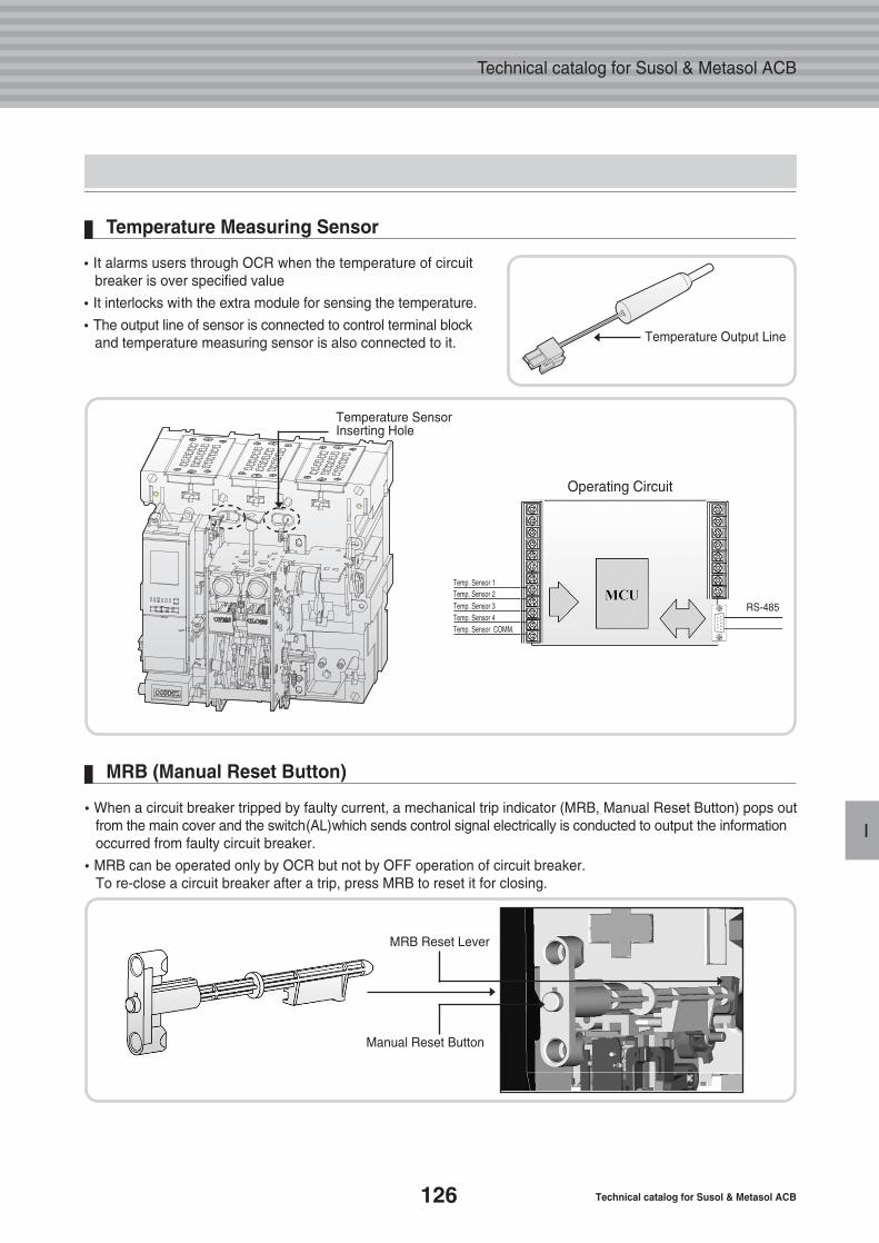
126 Technical catalog for Susol & Metasol ACB
Technical catalog for Susol & Metasol ACB
I
�When a circuit breaker tripped by faulty current, a mechanical trip indicator (MRB, Manual Reset Button) pops outfrom the main cover and the switch(AL)which sends control signal electrically is conducted to output the informationoccurred from faulty circuit breaker.
�MRB can be operated only by OCR but not by OFF operation of circuit breaker. To re-close a circuit breaker after a trip, press MRB to reset it for closing.
MRB (Manual Reset Button)
�It alarms users through OCR when the temperature of circuitbreaker is over specified value
�It interlocks with the extra module for sensing the temperature.
�The output line of sensor is connected to control terminal blockand temperature measuring sensor is also connected to it.
Temperature Measuring Sensor
Temperature SensorInserting Hole
MRB Reset Lever
Manual Reset Button
Temperature Output Line
RS-485
Temp. Sensor 1Temp. Sensor 2Temp. Sensor 3Temp. Sensor 4Temp. Sensor COMM.
Operating Circuit
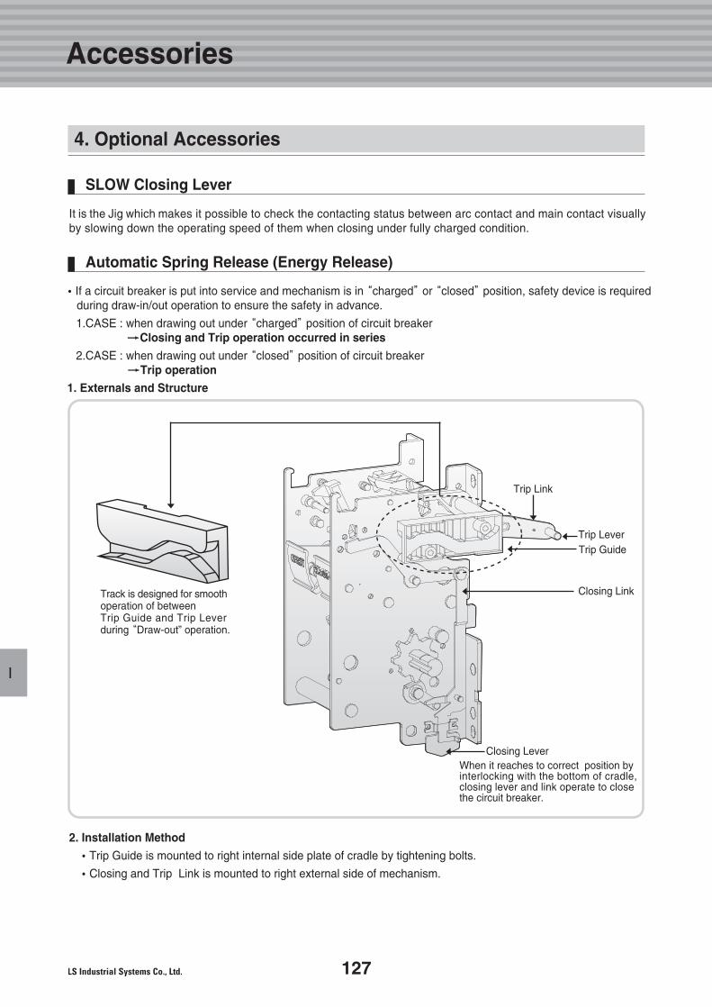
127
I
It is the Jig which makes it possible to check the contacting status between arc contact and main contact visuallyby slowing down the operating speed of them when closing under fully charged condition.
SLOW Closing Lever
�If a circuit breaker is put into service and mechanism is in “charged”or “closed”position, safety device is requiredduring draw-in/out operation to ensure the safety in advance.
1.CASE : when drawing out under “charged”position of circuit breaker�� Closing and Trip operation occurred in series
2.CASE : when drawing out under “closed”position of circuit breaker�� Trip operation
1. Externals and Structure
2. Installation Method
�Trip Guide is mounted to right internal side plate of cradle by tightening bolts.
�Closing and Trip Link is mounted to right external side of mechanism.
Automatic Spring Release (Energy Release)
Trip Link
Trip LeverTrip Guide
Closing Link
Closing LeverWhen it reaches to correct position by interlocking with the bottom of cradle,closing lever and link operate to closethe circuit breaker.
Track is designed for smoothoperation of betweenTrip Guide and Trip Leverduring “Draw-out” operation.
4. Optional Accessories
Accessories
Handling andMaintenance
129
131
132
134
1. Transporting and Storage
2. Check points before inspection
3. Inspection and maintenance
4. Defects and Troubleshootingguideline
J.
128 Technical catalog for Susol & Metasol ACB
Technical catalog for Susol & Metasol ACB
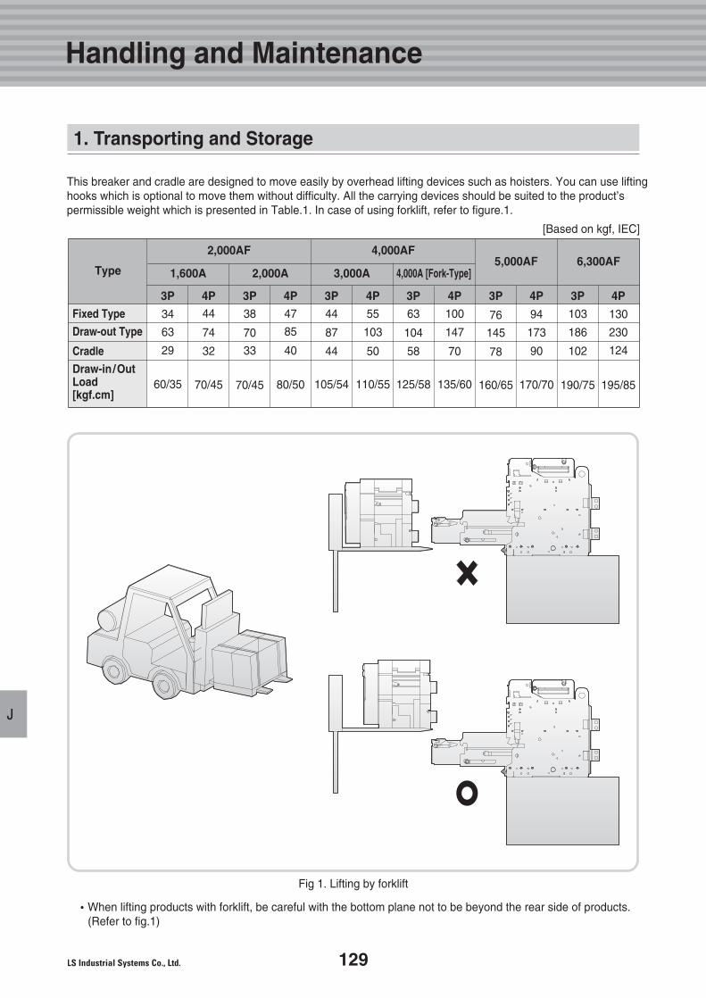
129
J
1. Transporting and Storage
Fig 1. Lifting by forklift
�When lifting products with forklift, be careful with the bottom plane not to be beyond the rear side of products.(Refer to fig.1)
This breaker and cradle are designed to move easily by overhead lifting devices such as hoisters. You can use liftinghooks which is optional to move them without difficulty. All the carrying devices should be suited to the product’spermissible weight which is presented in Table.1. In case of using forklift, refer to figure.1.
Type
2,000AF 4,000AF
Fixed Type
Draw-out Type
Cradle
Draw-in/OutLoad[kgf.cm]
3P
34
63
29
60/35
4P44
74
32
70/45
3P
38
70
33
70/45
4P
47
85
40
80/50
3P
44
87
44
105/54
4P
55
103
50
110/55
3P
63
104
58
125/58
4P
100
147
70
135/60
3P
76
145
78
160/65
4P
94
173
90
170/70
3P
103
186
102
190/75
4P
130
230
124
195/85
1,600A 2,000A 3,000A5,000AF 6,300AF
4,000A [Fork-Type]
Handling and Maintenance
[Based on kgf, IEC]
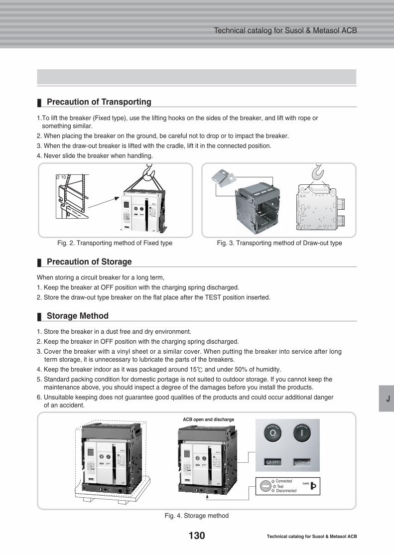
130 Technical catalog for Susol & Metasol ACB
Technical catalog for Susol & Metasol ACB
J
Fig. 2. Transporting method of Fixed type
∅ 10
Fig. 3. Transporting method of Draw-out type
1.To lift the breaker (Fixed type), use the lifting hooks on the sides of the breaker, and lift with rope orsomething similar.
2. When placing the breaker on the ground, be careful not to drop or to impact the breaker.
3. When the draw-out breaker is lifted with the cradle, lift it in the connected position.
4. Never slide the breaker when handling.
Precaution of Transporting
Fig. 4. Storage method
When storing a circuit breaker for a long term,
1. Keep the breaker at OFF position with the charging spring discharged.
2. Store the draw-out type breaker on the flat place after the TEST position inserted.
Precaution of Storage
1. Store the breaker in a dust free and dry environment.
2. Keep the breaker in OFF position with the charging spring discharged.
3. Cover the breaker with a vinyl sheet or a similar cover. When putting the breaker into service after longterm storage, it is unnecessary to lubricate the parts of the breakers.
4. Keep the breaker indoor as it was packaged around 15℃ and under 50% of humidity.
5. Standard packing condition for domestic portage is not suited to outdoor storage. If you cannot keep the maintenance above, you should inspect a degree of the damages before you install the products.
6. Unsuitable keeping does not guarantee good qualities of the products and could occur additional danger of an accident.
Storage Method
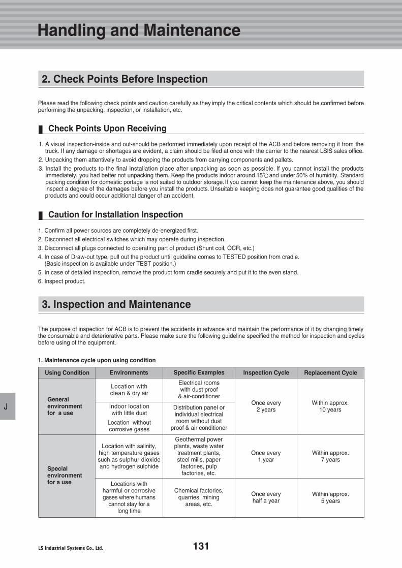
131
J
2. Check Points Before Inspection
1. A visual inspection-inside and out-should be performed immediately upon receipt of the ACB and before removing it from thetruck. If any damage or shortages are evident, a claim should be filed at once with the carrier to the nearest LSIS sales office.
2. Unpacking them attentively to avoid dropping the products from carrying components and pallets.3. Install the products to the final installation place after unpacking as soon as possible. If you cannot install the products
immediately, you had better not unpacking them. Keep the products indoor around 15℃and under 50% of humidity. Standardpacking condition for domestic portage is not suited to outdoor storage. If you cannot keep the maintenance above, you shouldinspect a degree of the damages before you install the products. Unsuitable keeping does not guarantee good qualities of theproducts and could occur additional danger of an accident.
Please read the following check points and caution carefully as they imply the critical contents which should be confirmed beforeperforming the unpacking, inspection, or installation, etc.
Check Points Upon Receiving
1. Confirm all power sources are completely de-energized first. 2. Disconnect all electrical switches which may operate during inspection. 3. Disconnect all plugs connected to operating part of product (Shunt coil, OCR, etc.) 4. In case of Draw-out type, pull out the product until guideline comes to TESTED position from cradle.
(Basic inspection is available under TEST position.)5. In case of detailed inspection, remove the product form cradle securely and put it to the even stand. 6. Inspect product.
Caution for Installation Inspection
3. Inspection and Maintenance
The purpose of inspection for ACB is to prevent the accidents in advance and maintain the performance of it by changing timelythe consumable and deteriorative parts. Please make sure the following guideline specified the method for inspection and cyclesbefore using of the equipment.
Using Condition
Generalenvironmentfor a use
Location withclean & dry air
Indoor locationwith little dust
Location withoutcorrosive gases
Electrical roomswith dust proof
& air-conditioner
Distribution panel orindividual electricalroom without dust
proof & air conditioner
Once every2 years
Within approx.10 years
Environments Specific Examples Inspection Cycle Replacement Cycle
Specialenvironmentfor a use
Location with salinity,high temperature gasessuch as sulphur dioxideand hydrogen sulphide
Locations withharmful or corrosivegases where humans
cannot stay for along time
Geothermal powerplants, waste watertreatment plants,steel mills, paper
factories, pulpfactories, etc.
Chemical factories,quarries, mining
areas, etc.
Once every1 year
Once everyhalf a year
Within approx.7 years
Within approx.5 years
1. Maintenance cycle upon using condition
Handling and Maintenance
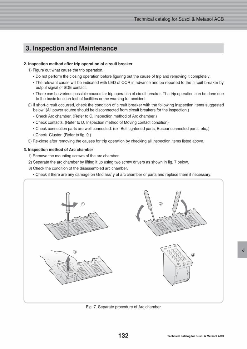
132 Technical catalog for Susol & Metasol ACB
Technical catalog for Susol & Metasol ACB
J
Fig. 7. Separate procedure of Arc chamber
2. Inspection method after trip operation of circuit breaker
1) Figure out what cause the trip operation.
�Do not perform the closing operation before figuring out the cause of trip and removing it completely.
�The relevant cause will be indicated with LED of OCR in advance and be reported to the circuit breaker byoutput signal of SDE contact.
�There can be various possible causes for trip operation of circuit breaker. The trip operation can be done dueto the basic function test of facilities or the warning for accident.
2) If short-circuit occurred, check the condition of circuit breaker with the following inspection items suggestedbelow. (All power source should be disconnected from circuit breakers for the inspection.)
�Check Arc chamber. (Refer to C. Inspection method of Arc chamber.)
�Check contacts. (Refer to D. Inspection method of Moving contact condition)
�Check connection parts are well connected. (ex. Bolt tightened parts, Busbar connected parts, etc,.)
�Check Cluster. (Refer to fig. 9.)
3) Re-close after removing the causes for trip operation by checking all inspection items listed above.
3. Inspection method of Arc chamber
1) Remove the mounting screws of the arc chamber.
2) Separate the arc chamber by lifting it up using two screw drivers as shown in fig. 7 below.
3) Check the condition of the disassembled arc chamber.
�Check if there are any damage on Grid ass’y of arc chamber or parts and replace them if necessary.
① ②
③④
3. Inspection and Maintenance
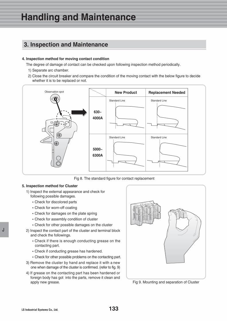
133
J
Fig 9. Mounting and separation of Cluster
Fig 8. The standard figure for contact replacement
4. Inspection method for moving contact condition
The degree of damage of contact can be checked upon following inspection method periodically.
1) Separate arc chamber.
2) Close the circuit breaker and compare the condition of the moving contact with the below figure to decidewhether it is to be replaced or not.
5. Inspection method for Cluster
1) Inspect the external appearance and check for following possible damages.
�Check for discolored parts
�Check for worn-off coating
�Check for damages on the plate spring
�Check for assembly condition of cluster
�Check for other possible damages on the cluster
2) Inspect the contact part of the cluster and terminal block and check the followings.
�Check if there is enough conducting grease on thecontacting part.
�Check if conducting grease has hardened.
�Check for other possible problems on the contacting part.
3) Remove the cluster by hand and replace it with a newone when damage of the cluster is confirmed. (refer to fig. 9)
4) If grease on the contacting part has been hardened orforeign body has got into the parts, remove it clean andapply new grease.
Handling and Maintenance
New Product
Standard Line Standard Line
Standard Line Standard Line
Observation spot Replacement Needed
3. Inspection and Maintenance
630~
4000A
5000~
6300A
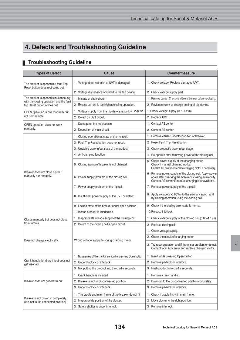
134 Technical catalog for Susol & Metasol ACB
Technical catalog for Susol & Metasol ACB
J
4. Defects and Troubleshooting Guideline
Troubleshooting Guideline
The breaker is opened but fault TripReset button does mot come out.
1. Voltage does not exist or UVT is damaged.
1. In state of short-circuit
2. Excess current is too high at closing operation.
1. Voltage supply from the trip device is too low. V 0.7Vn
2. Defect on UVT circuit.
1. Damage on the mechanism
2. Deposition of main circuit.
1. Closing operation at state of short-circuit.
2. Fault Trip Reset button does not reset.
3. Unstable draw-in/out state of the product.
4. Anti-pumping function
5. Closing spring of breaker is not charged.5. Check power supply of the charging motor.
Check if manual charging works. Contact AS center or replace charging motor if necessary.
6. Remove power supply of the closing coil. Apply poweragain after checking the breaker’s closing availability.Contact AS center if manual charging is unavailable.
8. Apply voltage(V 0.85Vn) to the auxiliary switch and try closing operation using the closing coil.
1. Check voltage supply of the closing coil.(0.85~1.1Vn)
7. Remove power supply of the trip coil.
3. Try reset operation and if there is a problem or defect.Contact local AS center and replace charging motor.
1. Remove crank handle.
2. Draw out to the Disconnected position completely.
3. Remove padlock or interlock.
9. Check if the closing error state is normal.
10.Release interlock.
2. Replace closing coil.
1. Check voltage supply.
2. Check the circuit of charging motor.
1. Insert while pressing Open button
2. Remove padlock or interlock.
3. Rush product into cradle securely.
1. Check voltage. Replace damaged UVT.
2. Check voltage supply part.
1. Remove cause : Check condition of breaker before re-closing.
2. Revise network or change setting of trip device.
1. Check voltage supply.(0.7~1.1Vn)
2. Replace UVT.
1. Contact AS center
2. Contact AS center
1. Remove cause : Check condition or breaker.
2. Reset Fault Trip Reset button
3. Check product’s draw-in/out stage.
4. Re-operate after removing power of the closing coil.
6. Power supply problem of the closing coil.
8. Insufficient power supply of the UVT or defect.
9. Locked state of the breaker under open position
10.Incase breaker is interlocked.
1. Inappropriate voltage supply of the closing coil.
2. Defect of the closing coil,s open circuit.
1. No opening of the crank insertion by pressing Open button
2. Under Padlock or interlock
3. Not putting the product into the cradle securely.
1. Crank handle is inserted.
2. Breaker is not in Disconnected position
3. Under Padlock or interlock
1. The cradle and main frame of the breaker do not fit
2. Inappropriate position of the cluster.
3. Safety shutter is under interlock.
1. Check if cradle fits with main frame.
2. Move cluster to the right position.
3. Remove interlock.
Wrong voltage supply to spring charging motor.
7. Power supply problem of the trip coil.
2. Voltage disturbance occurred to the trip device
OPEN operation is doe manually butnot from remote.
OPEN operation does not workmanually.
Closes manually but does not closefrom remote.
Dose not charge electrically.
Crank handle for draw-in/out does notget inserted.
Breaker does not get drawn out.
Breaker is not drawn in completely.(It is not in the connected position)
Breaker does not close neithermanually nor remotely.
The breaker is opened simultaneouslywith the closing operation and the faulttrip Reset button comes out.
Types of Defect Cause Countermeasure
K.136
138
1. Control Circuit
2. External Dimension
Control Circuitand Dimension
135
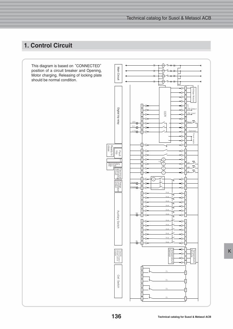
136 Technical catalog for Susol & Metasol ACB
Technical catalog for Susol & Metasol ACB
K
1. Control Circuit
This diagram is based on “CONNECTED”position of a circuit breaker and Opening,Motor charging, Releasing of locking plateshould be normal condition.
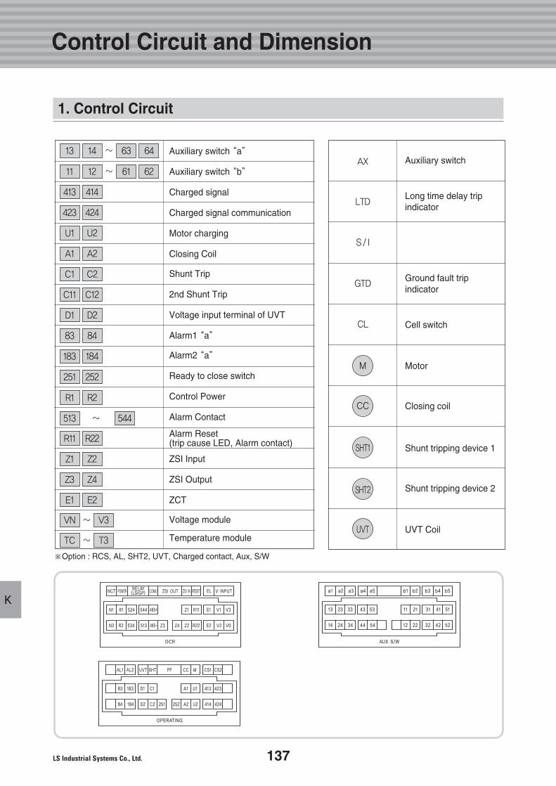
137
K
Control Circuit and Dimension
1. Control Circuit
Auxiliary switch “a”
Auxiliary switch “b”
Charged signal
Charged signal communication
Motor charging
Closing Coil
Shunt Trip
2nd Shunt Trip
Voltage input terminal of UVT
Alarm1 “a”
Alarm2 “a”
Ready to close switch
Control Power
Alarm Contact
Alarm Reset(trip cause LED, Alarm contact)
ZSI Input
ZSI Output
ZCT
Voltage module
Temperature module
~13
※Option : RCS, AL, SHT2, UVT, Charged contact, Aux, S/W
Auxiliary switch
Long time delay tripindicator
Ground fault tripindicator
Cell switch
Motor
Closing coil
Shunt tripping device 1
Shunt tripping device 2
UVT Coil
~
~
~
~
AX
LTD
S/I
GTD
CL
M
CC
SHT1
SHT2
UVT
14 63 64
11 12 61 62
413 414
423 424
U1 U2
A1 A2
C1 C2
C11 C12
D1 D2
83 84
251 252
183 184
R1 R2
513 544
R11 R22
Z1 Z2
Z3 Z4
E1 E2
VN V3
TC T3
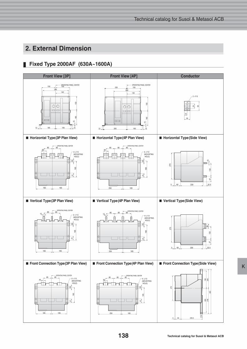
138 Technical catalog for Susol & Metasol ACB
Technical catalog for Susol & Metasol ACB
K
2. External Dimension
Fixed Type 2000AF (630A~1600A)
Front View [3P] Front View [4P] Conductor
■■ Horizontal Type(3P Plan View) ■■ Horizontal Type(4P Plan View) ■■ Horizontal Type(Side View)
■■ Vertical Type(3P Plan View) ■■ Vertical Type(4P Plan View) ■■ Vertical Type(Side View)
■■ Front Connection Type(3P Plan View) ■■ Front Connection Type(4P Plan View) ■■ Front Connection Type(Side View)
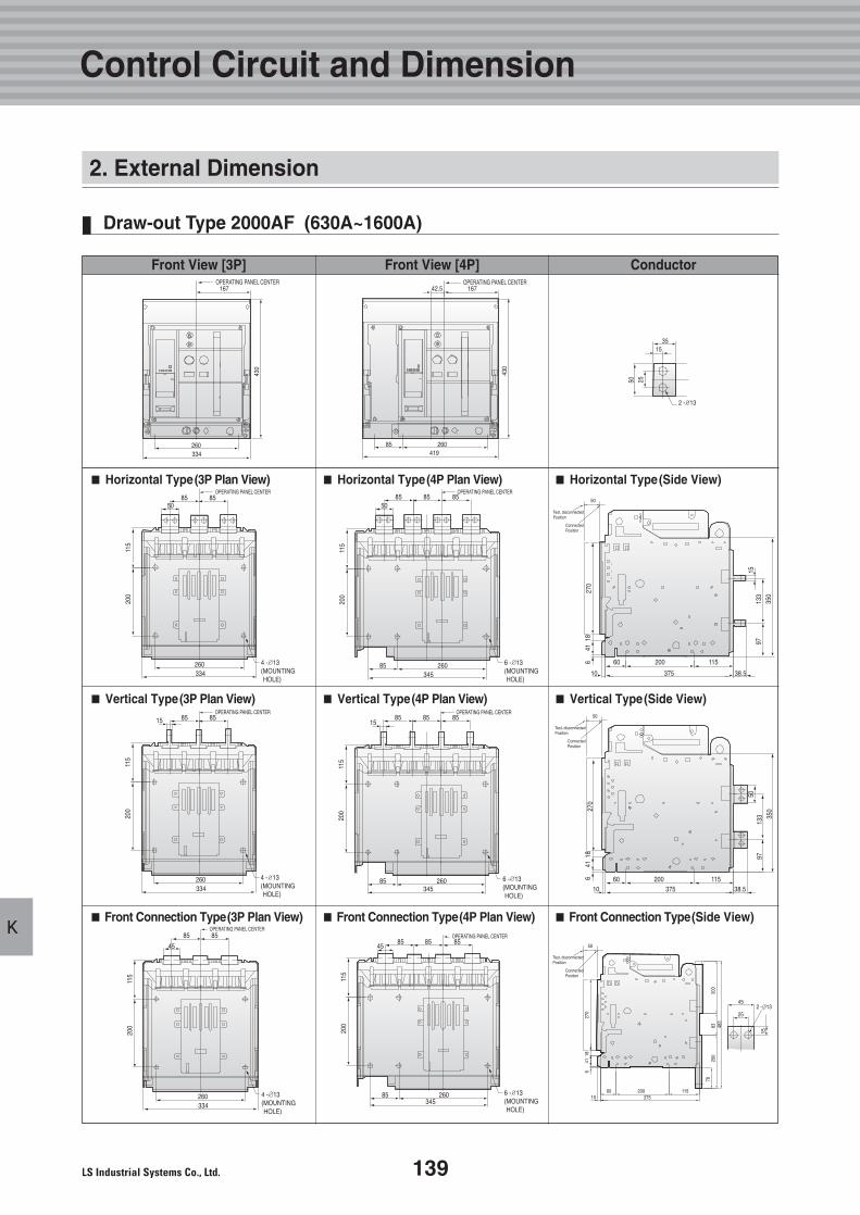
139
K
Draw-out Type 2000AF (630A~1600A)
Control Circuit and Dimension
Front View [3P] Front View [4P] Conductor
■■ Horizontal Type(3P Plan View) ■■ Horizontal Type(4P Plan View) ■■ Horizontal Type(Side View)
■■ Vertical Type(3P Plan View) ■■ Vertical Type(4P Plan View) ■■ Vertical Type(Side View)
■■ Front Connection Type(3P Plan View) ■■ Front Connection Type(4P Plan View) ■■ Front Connection Type(Side View)
2. External Dimension
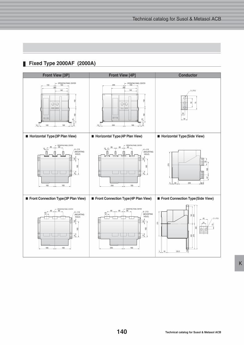
140 Technical catalog for Susol & Metasol ACB
Technical catalog for Susol & Metasol ACB
K
Fixed Type 2000AF (2000A)
■■ Horizontal Type(3P Plan View) ■■ Horizontal Type(4P Plan View) ■■ Horizontal Type(Side View)
■■ Front Connection Type(3P Plan View) ■■ Front Connection Type(4P Plan View) ■■ Front Connection Type(Side View)
Front View [3P] Front View [4P] Conductor
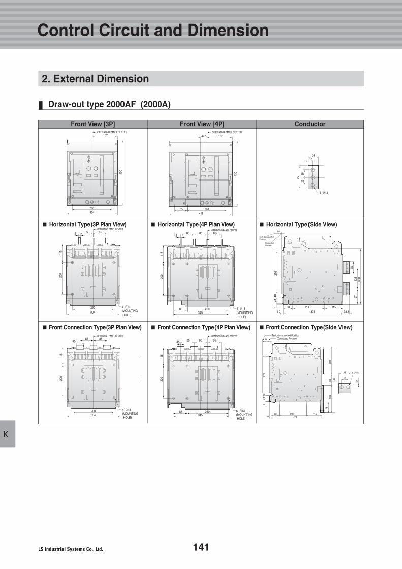
141
K
Draw-out type 2000AF (2000A)
Control Circuit and Dimension
■■ Horizontal Type(3P Plan View) ■■ Horizontal Type(4P Plan View) ■■ Horizontal Type(Side View)
■■ Front Connection Type(3P Plan View) ■■ Front Connection Type(4P Plan View) ■■ Front Connection Type(Side View)
Front View [3P] Front View [4P] Conductor
2. External Dimension
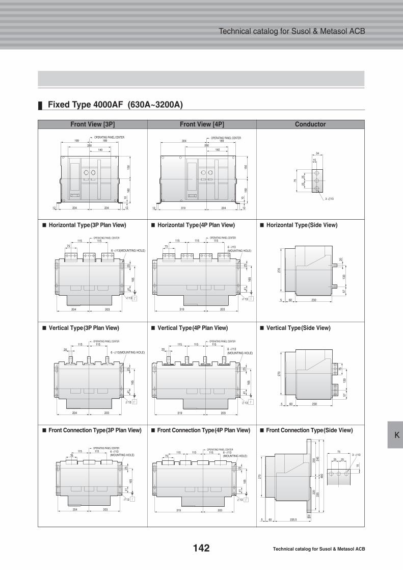
142 Technical catalog for Susol & Metasol ACB
Technical catalog for Susol & Metasol ACB
K
Fixed Type 4000AF (630A~3200A)
75
■■ Horizontal Type(3P Plan View) ■■ Horizontal Type(4P Plan View) ■■ Horizontal Type(Side View)
■■ Vertical Type(3P Plan View) ■■ Vertical Type(4P Plan View) ■■ Vertical Type(Side View)
■■ Front Connection Type(3P Plan View) ■■ Front Connection Type(4P Plan View) ■■ Front Connection Type(Side View)
Front View [3P] Front View [4P] Conductor
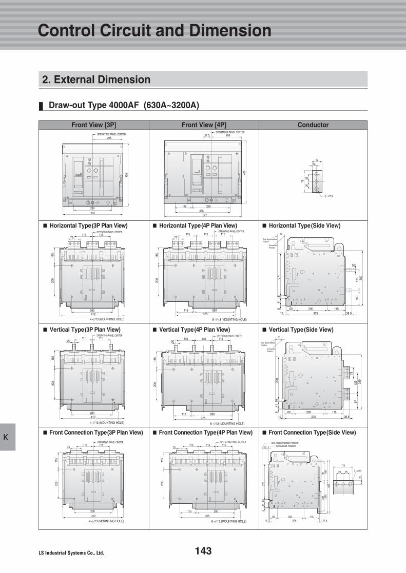
143
K
Draw-out Type 4000AF (630A~3200A)
Control Circuit and Dimension
■■ Horizontal Type(3P Plan View) ■■ Horizontal Type(4P Plan View) ■■ Horizontal Type(Side View)
■■ Vertical Type(3P Plan View) ■■ Vertical Type(4P Plan View) ■■ Vertical Type(Side View)
■■ Front Connection Type(3P Plan View) ■■ Front Connection Type(4P Plan View) ■■ Front Connection Type(Side View)
Front View [3P] Front View [4P] Conductor
2. External Dimension
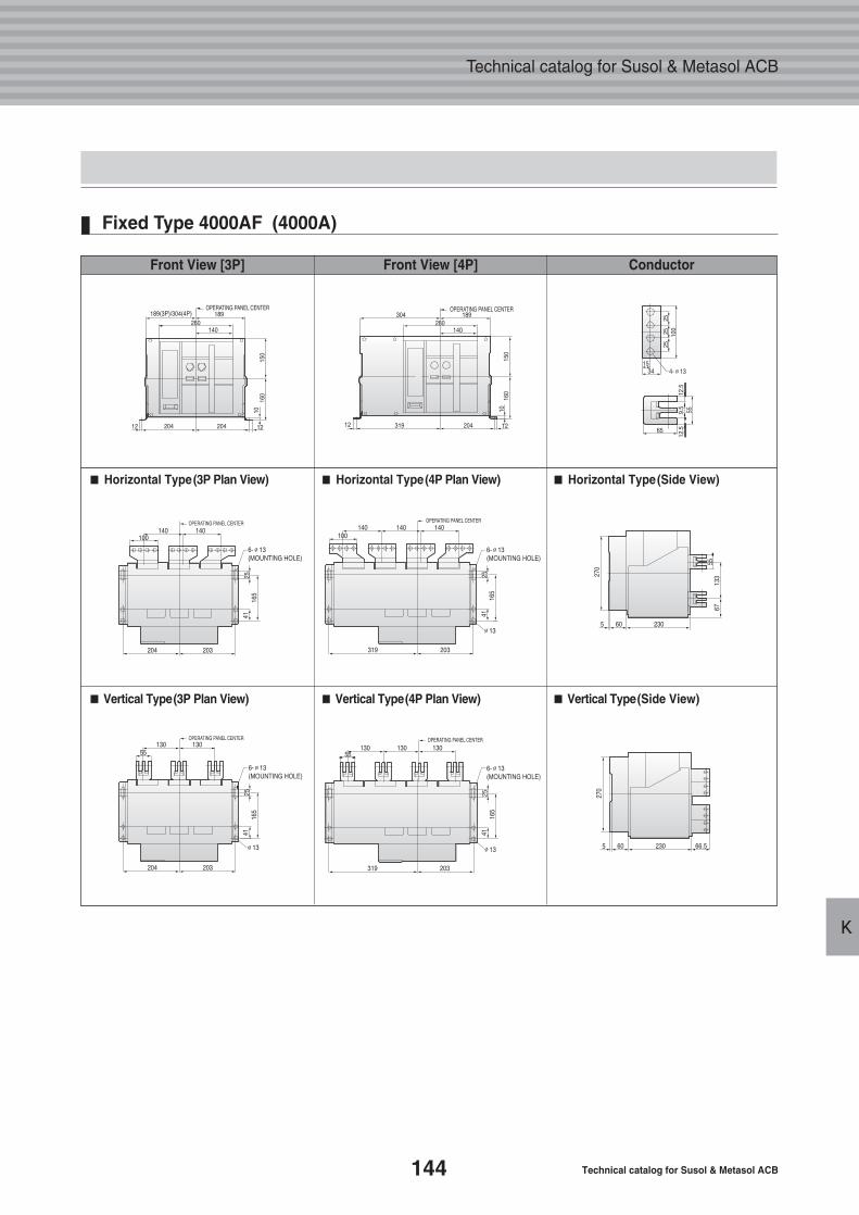
144 Technical catalog for Susol & Metasol ACB
Technical catalog for Susol & Metasol ACB
K
Fixed Type 4000AF (4000A)
12.5
12.5
9.5
■■ Horizontal Type(3P Plan View) ■■ Horizontal Type(4P Plan View) ■■ Horizontal Type(Side View)
■■ Vertical Type(3P Plan View) ■■ Vertical Type(4P Plan View) ■■ Vertical Type(Side View)
Front View [3P] Front View [4P] Conductor
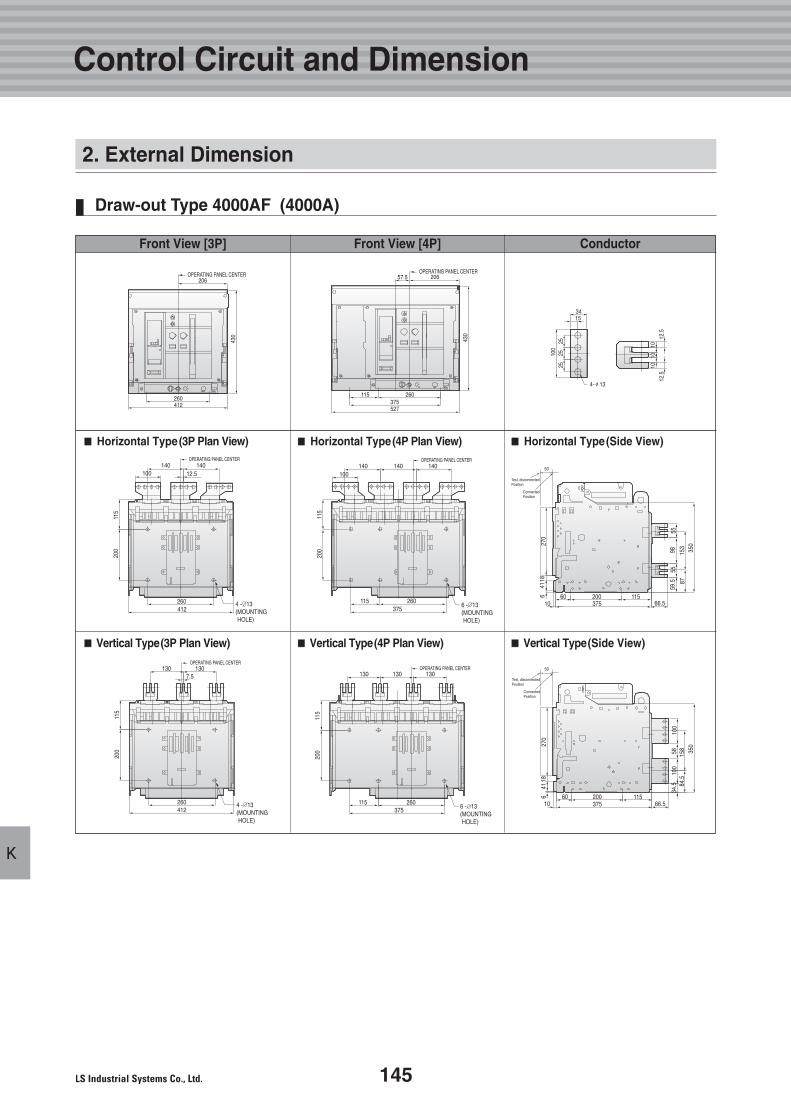
145
K
Draw-out Type 4000AF (4000A)
Control Circuit and Dimension
■■ Horizontal Type(3P Plan View) ■■ Horizontal Type(4P Plan View) ■■ Horizontal Type(Side View)
■■ Vertical Type(3P Plan View) ■■ Vertical Type(4P Plan View) ■■ Vertical Type(Side View)
Front View [3P] Front View [4P] Conductor
2. External Dimension
140100 12.5
260412
140
200
115
OPERATING PANEL CENTER
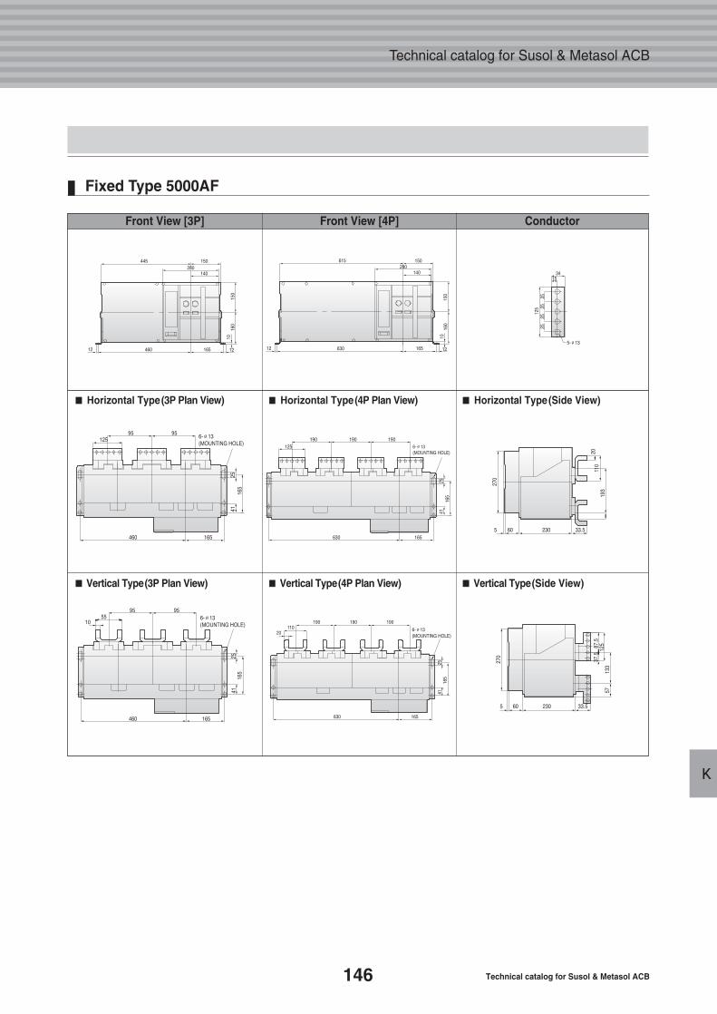
146 Technical catalog for Susol & Metasol ACB
Technical catalog for Susol & Metasol ACB
K
Fixed Type 5000AF
■■ Horizontal Type(3P Plan View) ■■ Horizontal Type(4P Plan View) ■■ Horizontal Type(Side View)
■■ Vertical Type(3P Plan View) ■■ Vertical Type(4P Plan View) ■■ Vertical Type(Side View)
Front View [3P] Front View [4P] Conductor
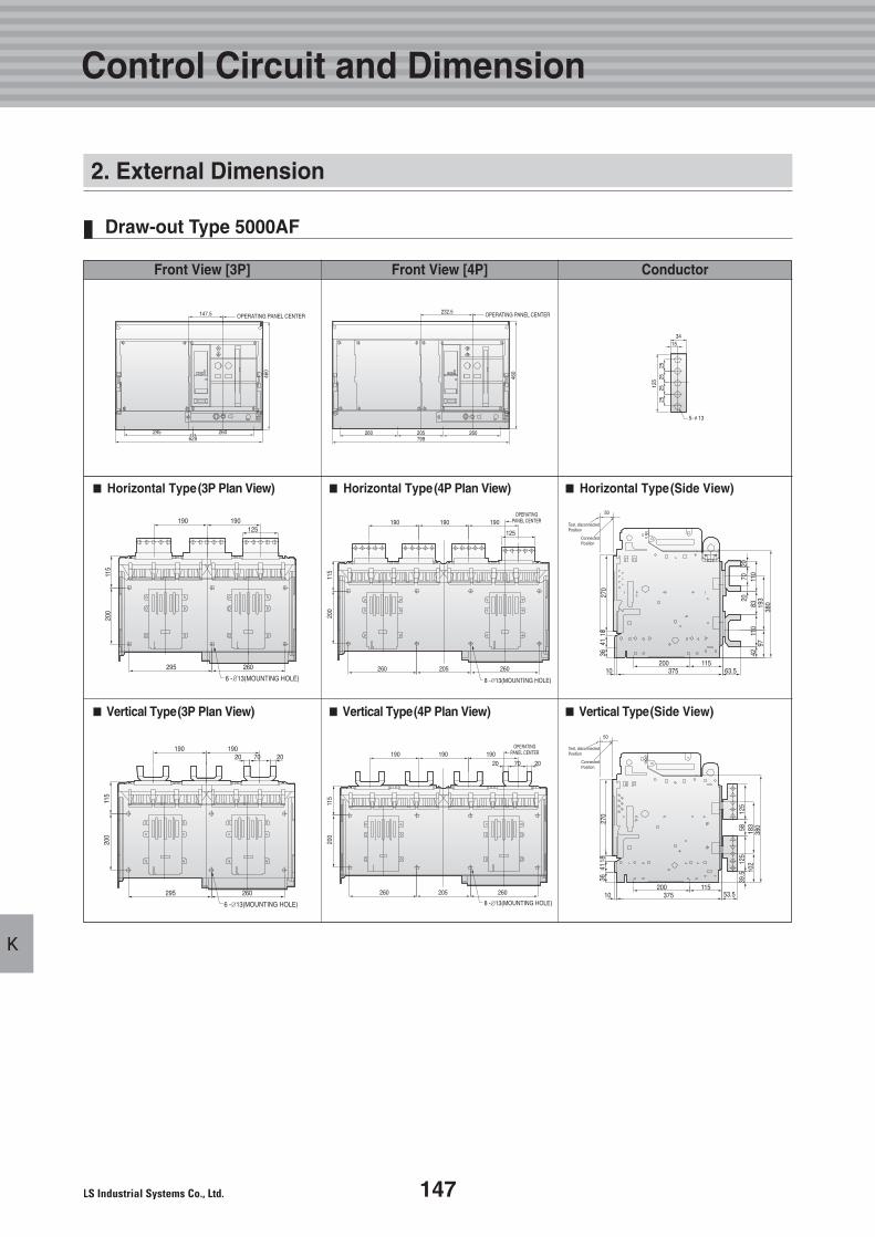
147
K
Draw-out Type 5000AF
Control Circuit and Dimension
■■ Horizontal Type(3P Plan View) ■■ Horizontal Type(4P Plan View) ■■ Horizontal Type(Side View)
■■ Vertical Type(3P Plan View) ■■ Vertical Type(4P Plan View) ■■ Vertical Type(Side View)
Front View [3P] Front View [4P] Conductor
2. External Dimension
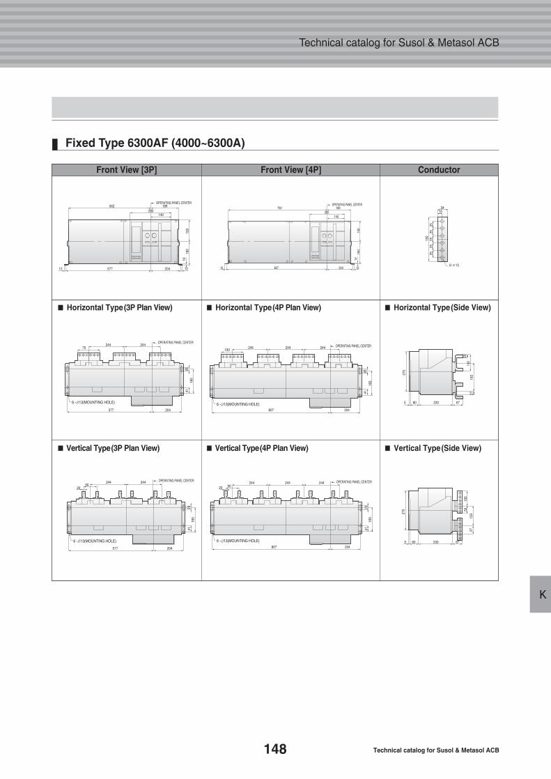
148 Technical catalog for Susol & Metasol ACB
Technical catalog for Susol & Metasol ACB
K
Fixed Type 6300AF (4000~6300A)
■■ Horizontal Type(3P Plan View) ■■ Horizontal Type(4P Plan View) ■■ Horizontal Type(Side View)
■■ Vertical Type(3P Plan View) ■■ Vertical Type(4P Plan View) ■■ Vertical Type(Side View)
Front View [3P] Front View [4P] Conductor
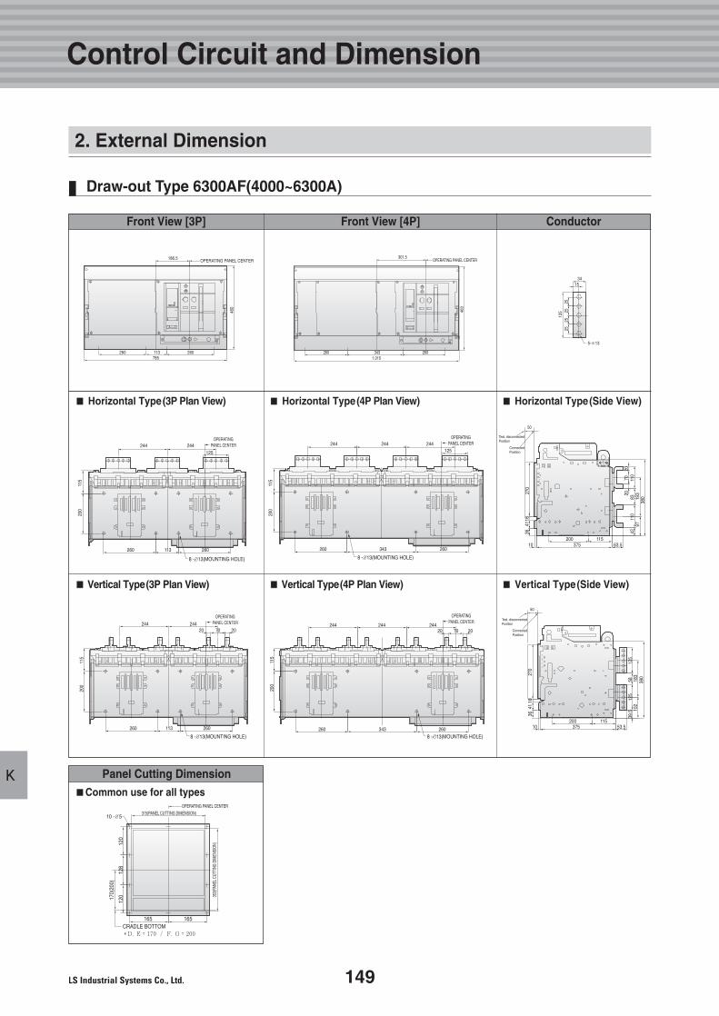
149
K
Draw-out Type 6300AF(4000~6300A)
Control Circuit and Dimension
Panel Cutting Dimension
CRADLE BOTTOM�D, E = 170 / F, G = 200
165 165
120
12017
0(20
0)
128
OPERATING PANEL CENTER
315(PANEL CUTTING DIMENSION)
353(
PANE
L CUT
TING
DIM
ENSI
ON)
10 - 5
■■Common use for all types
■■ Horizontal Type(3P Plan View) ■■ Horizontal Type(4P Plan View) ■■ Horizontal Type(Side View)
■■ Vertical Type(3P Plan View) ■■ Vertical Type(4P Plan View) ■■ Vertical Type(Side View)
Front View [3P] Front View [4P] Conductor
2. External Dimension
Technical catalog for Susol & Metasol ACB
L.Ordering Sheet
1511. Susol/Metasol ACB
150 Technical catalog for Susol & Metasol ACB
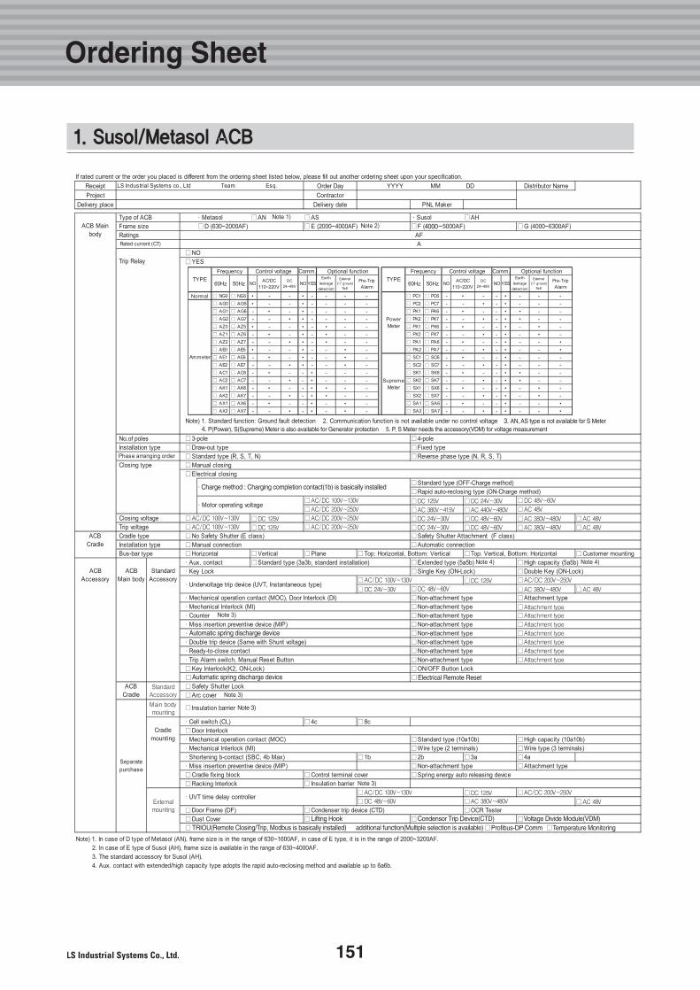
3. AN, AS type is not available for S Meter
Charge method : Charging completion contact(1b) is basically installed
Automatic spring discharge device
Automatic spring discharge device
Lifting HookTRIOU(Remote Closing/Trip, Modbus is basically installed) additional function(Multiple selection is available)
Condensor Trip Device(CTD) Voltage Divide Module(VDM)Profibus-DP Comm Temperature Monitoring
Note 3)
4. P(Power), S(Supreme) Meter is also available for Generator protection 5. P, S Meter needs the accessory(VDM) for voltage measurement
Electrical Remote Reset
1. Susol/Metasol ACB
151
Ordering Sheet
152 Technical catalog for Susol & Metasol ACB
Technical catalog for Susol & Metasol ACB
Memo
153
Technical Materials
Memo
11
Super solution
Meta solution
Technical catalog for Susol & Metasol ACB
This technical document can be revised or withdrawn at any timewithout prior notice. No part of this publication shall be reproducedor utilized in any form or by any means. The persons who are in breach of terms and conditions will be subjected to compensatefor any loss lf our company.All patent rights are reserved.
Title : Technical catalogue of Susol&metasol ACB
Document No : Tech, ACB 695-001
Issued team : Electric equip.)Technology management team
Issued date : June, 2007
154 Technical materials for Susol & Metasol ACB
S u p e r S o l u t i o n
Technical Catalog for Susol&Metasol ACB 2007.07/ (02) 2012.10 HUMANPOWER
�� HEAD OFFICEYonsei Jaedan Severance Bldg., 84-11, Namdaemunro 5-ga, Jung-gu,Seoul 100-753, KoreaTe l. (82-2)2034-4870 Fax. (82-2)2034-4713
�� Cheong-Ju PlantCheong-Ju Plant #1, Song Jung Dong, Hung Duk Ku, Cheong Ju,361-720, KoreaTe l. (82-43)261-6001 Fax. (82-43)261-6410
Specifications in this technical catalog are subject to change withoutnotice due to continuous products development and improvement.