Embed Size (px)
Citation preview
Analysis MEMO
Magnetic field shield for
S-2S TOF detector
9Mar2015Toshiyuki Gogami
Contents
考えていた TOF 用磁気シールドのシールド性能の TOSCA 計算によるスタディ
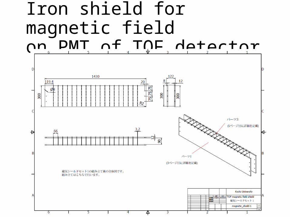
Iron shield for magnetic field on PMT of TOF detector
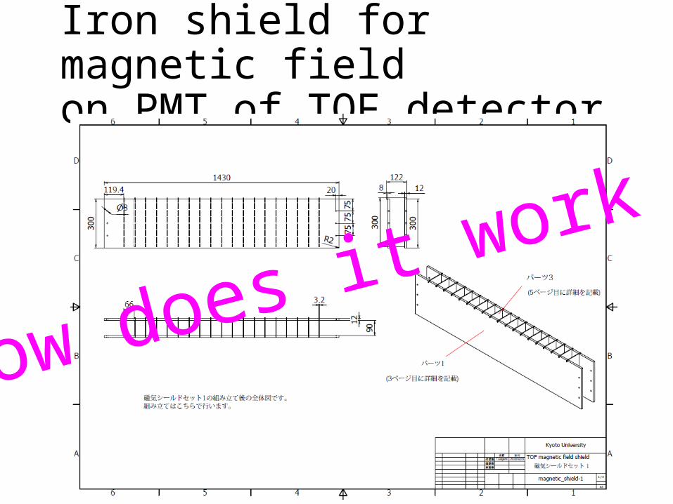
Iron shield for magnetic field on PMT of TOF detector
How does it work ?
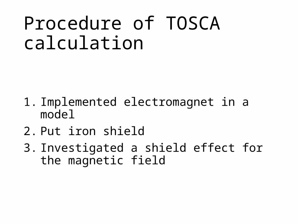
Procedure of TOSCA calculation
1. Implemented electromagnet in a model2. Put iron shield 3. Investigated a shield effect for the magnetic field
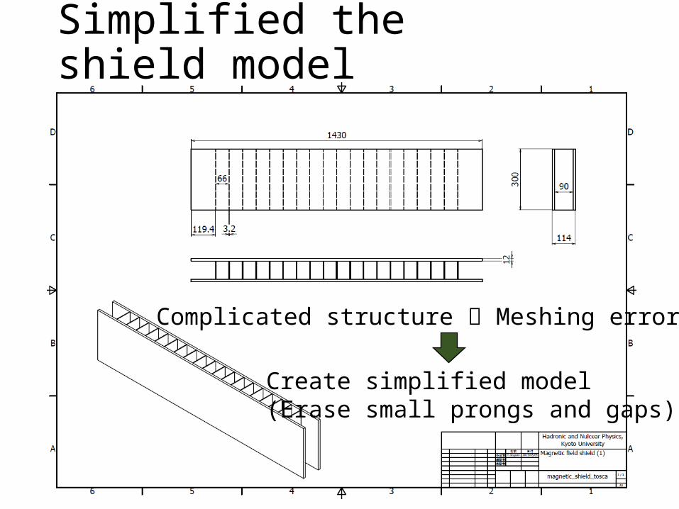
Simplified the shield model
Complicated structure Meshing error
Create simplified model (Erase small prongs and gaps)
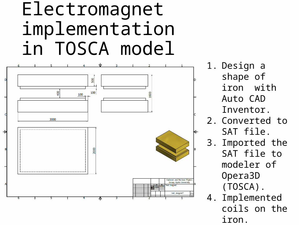
Electromagnet implementationin TOSCA model
1. Design a shape of iron with Auto CAD Inventor.
2. Converted to SAT file.
3. Imported the SAT file to modeler of Opera3D (TOSCA).
4. Implemented coils on the iron.
5. Optimized the current density.
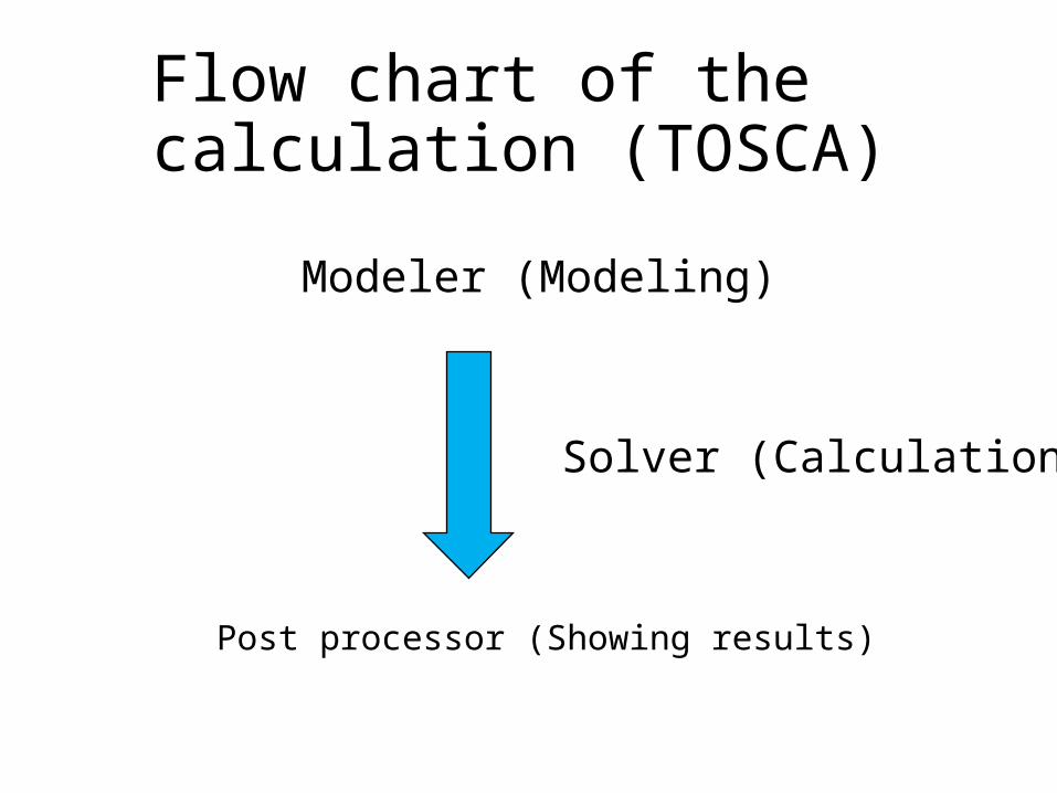
Flow chart of the calculation (TOSCA)
Post processor (Showing results)
Modeler (Modeling)
Solver (Calculation)
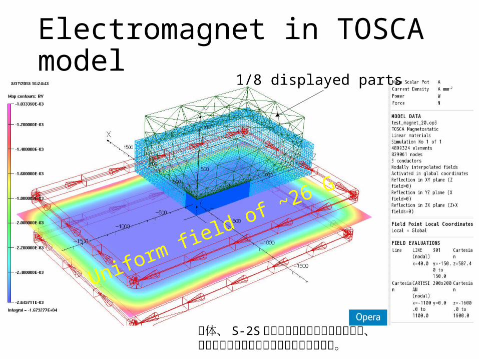
Electromagnet in TOSCA model
Uniform field of ~26 G
1/8 displayed parts
大体、 S-2S の漏れ磁場がこれくらいなので、さし当りこの設定でスタディを進めました。
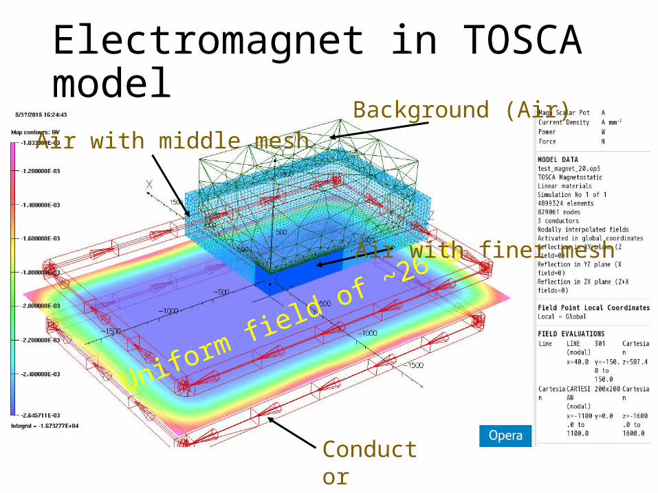
Electromagnet in TOSCA model
Uniform field of ~26 G
Background (Air)
Air with finer mesh
Air with middle mesh
Conductor

Put iron shield in the electromagnet
zx
y
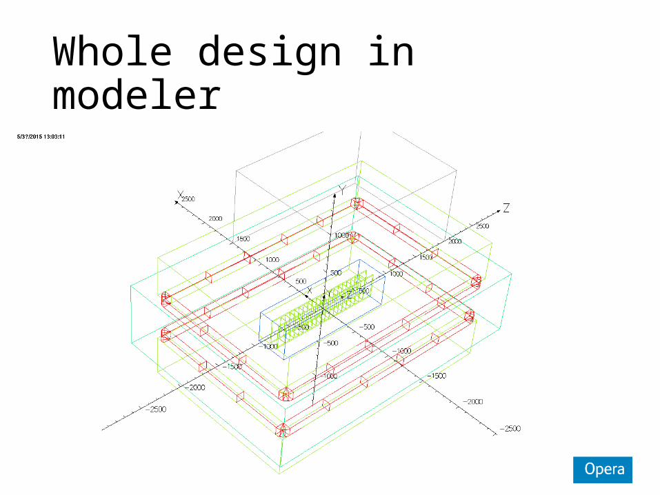
Whole design in modeler
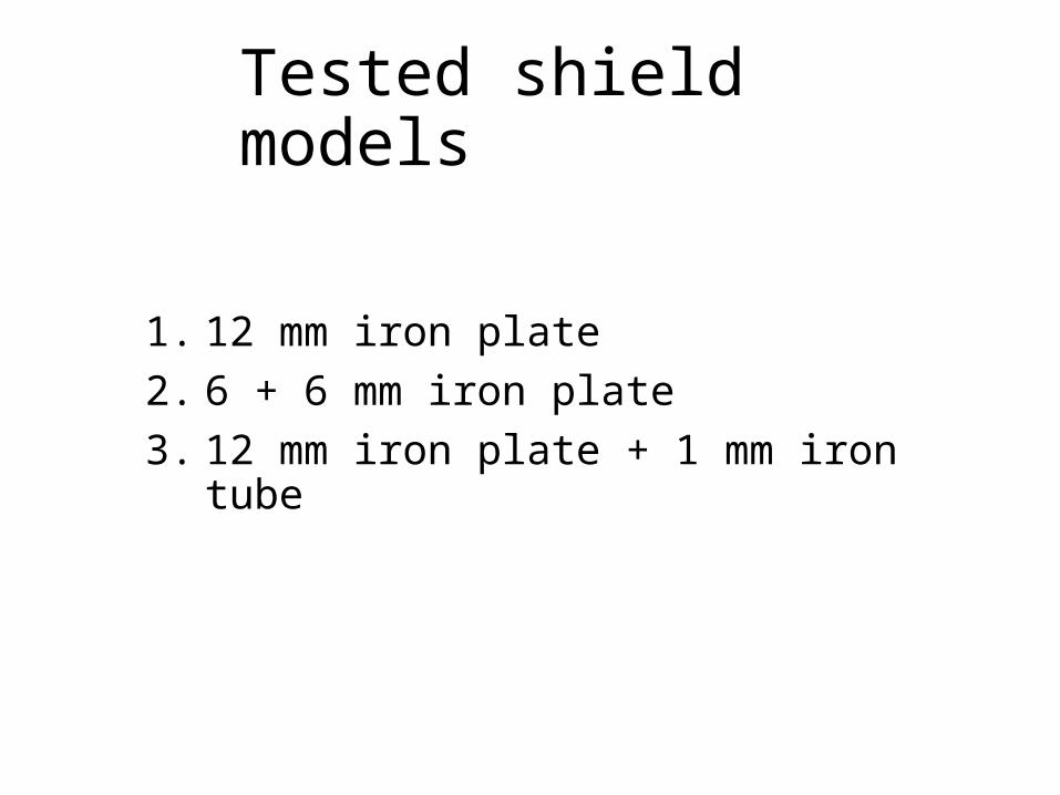
Tested shield models
1. 12 mm iron plate2. 6 + 6 mm iron plate3. 12 mm iron plate + 1 mm iron tube
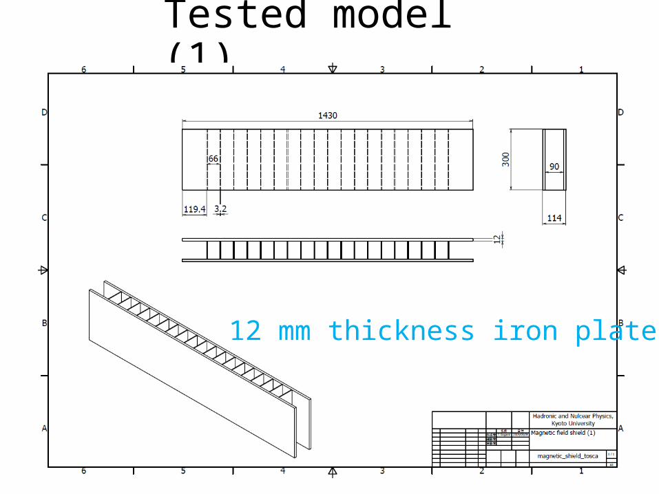
Tested model (1)
12 mm thickness iron plate
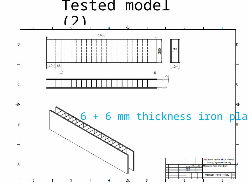
Tested model (2)
6 + 6 mm thickness iron plate
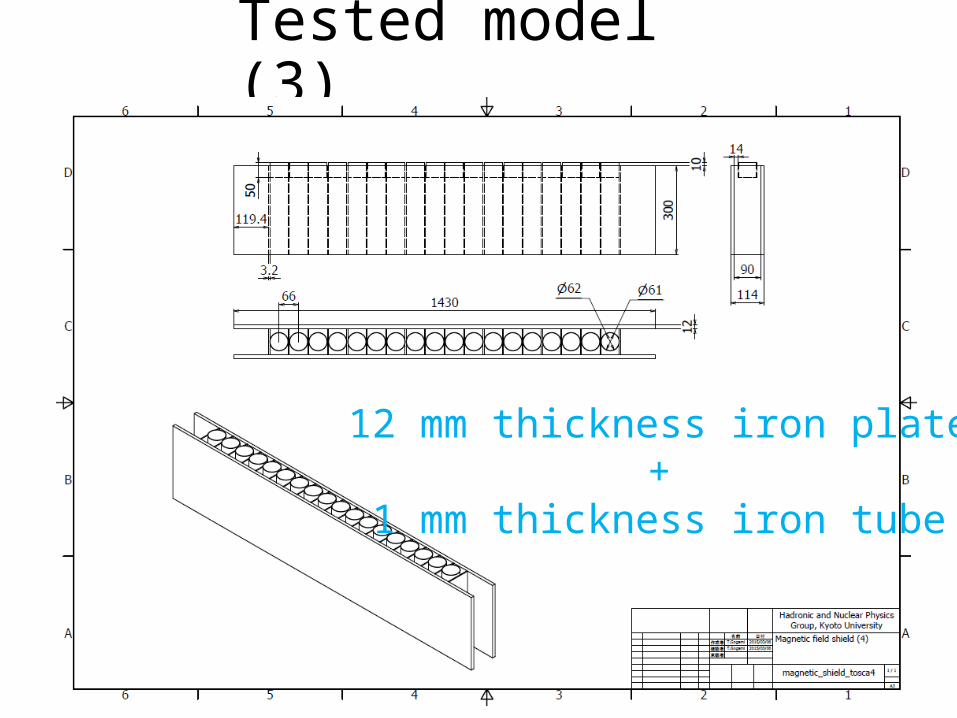
Tested model (3)
12 mm thickness iron plate+
1 mm thickness iron tube
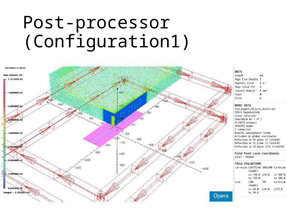
Post-processor (Configuration1)
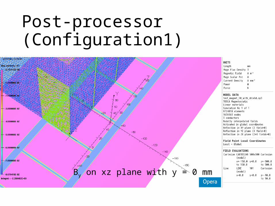
Post-processor (Configuration1)
By on xz plane with y = 0 mm
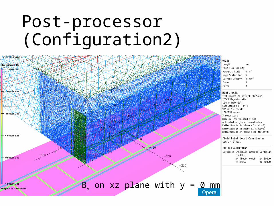
Post-processor (Configuration2)
By on xz plane with y = 0 mm
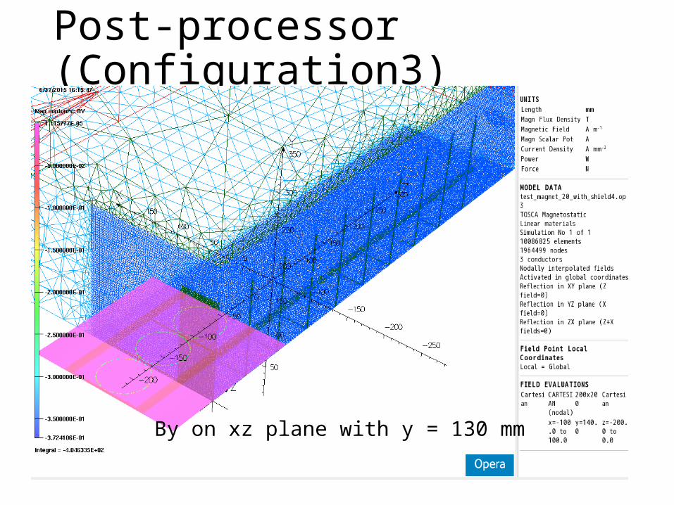
Post-processor (Configuration3)
By on xz plane with y = 130 mm
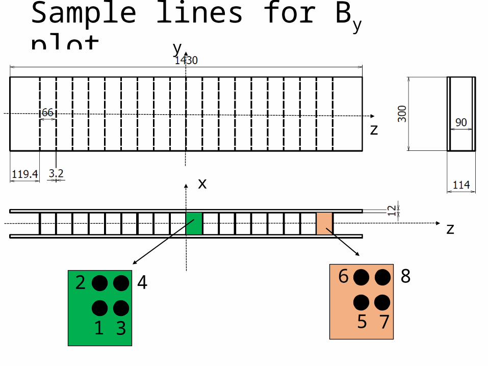
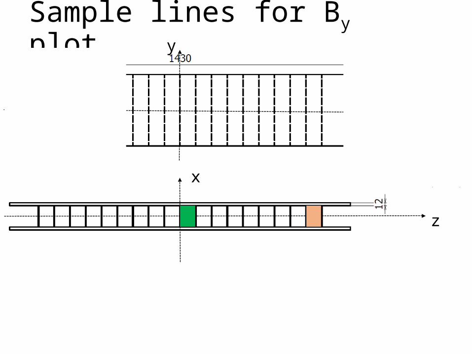
Sample lines for By plot
1
2
3
4
5
6
7
8
z
x
z
y
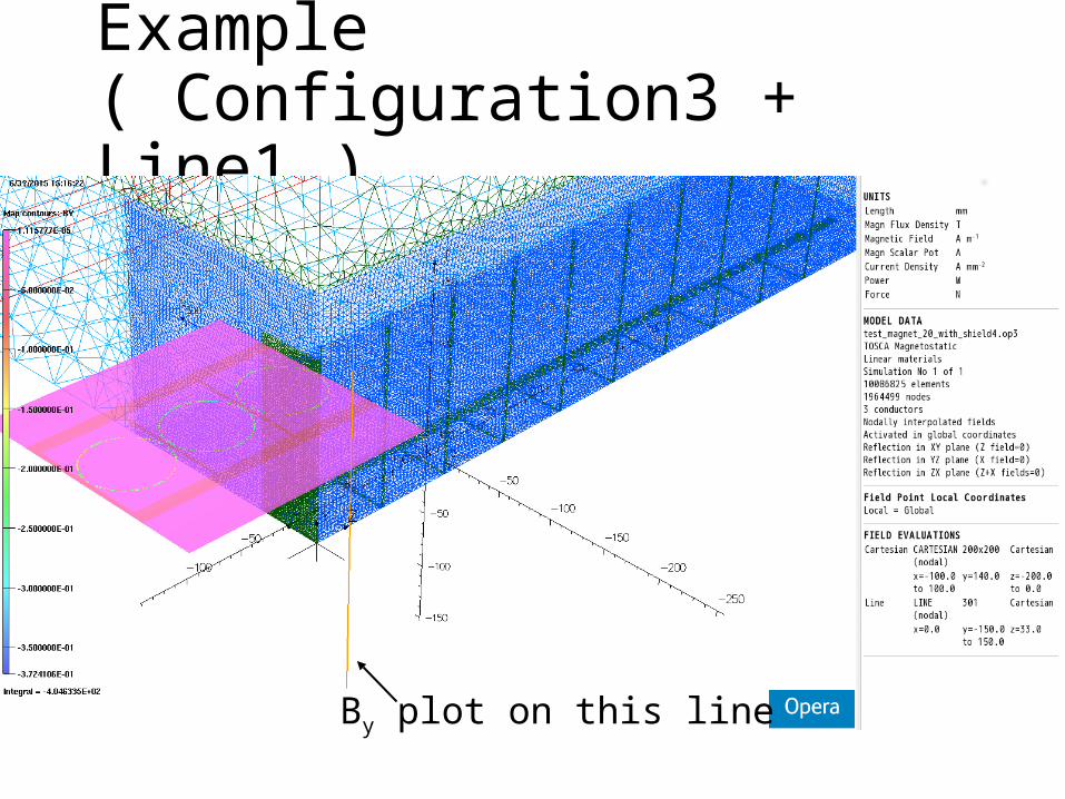
Example ( Configuration3 + Line1 )
By plot on this line
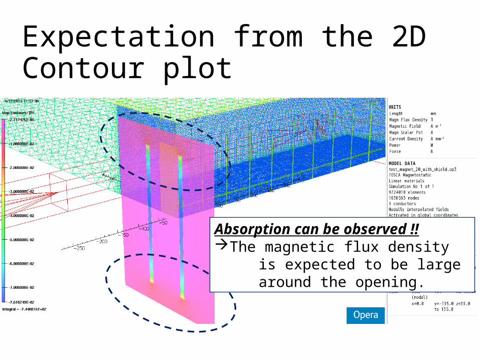
Expectation from the 2D Contour plot
Absorption can be observed !!The magnetic flux density is expected to be large around the opening.
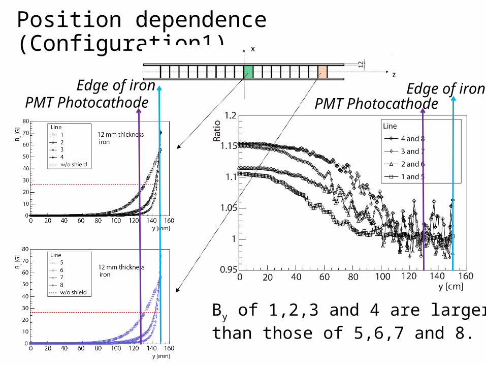
Position dependence (Configuration1)
By of 1,2,3 and 4 are largerthan those of 5,6,7 and 8.
Edge of ironEdge of ironPMT Photocathode PMT Photocathode
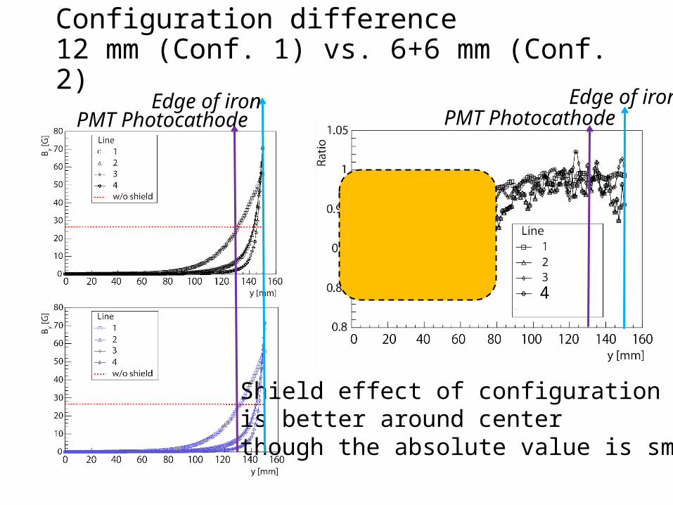
Configuration difference 12 mm (Conf. 1) vs. 6+6 mm (Conf. 2)
4
Shield effect of configuration 2 is better around centerthough the absolute value is small.
Edge of ironEdge of ironPMT Photocathode PMT Photocathode
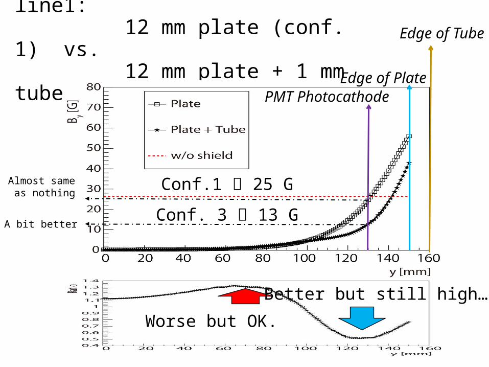
Configuration difference on line1: 12 mm plate (conf. 1) vs. 12 mm plate + 1 mm tube (conf. 3)
Better but still high…
Worse but OK.
Edge of PlatePMT Photocathode
Conf. 3 13 G
Conf.1 25 GAlmost same as nothing
A bit better
Edge of Tube
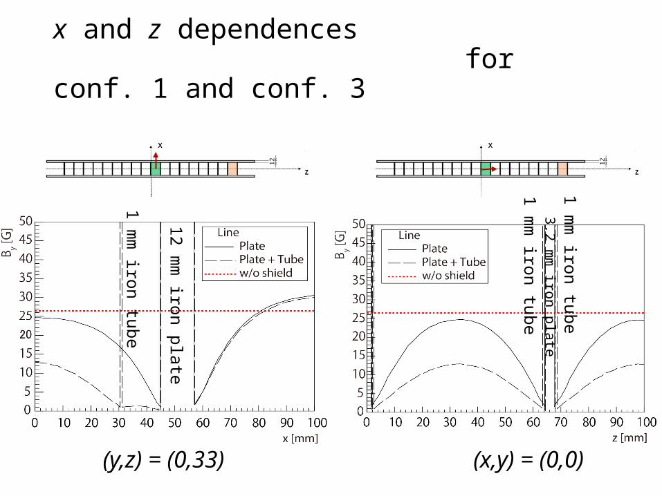
x and z dependences for conf. 1 and conf. 3
(y,z) = (0,33) (x,y) = (0,0)
1 mm
iron tube
12 mm
iron plate
1 mm
iron tube3.2 m
m iron plate
1 mm
iron tube
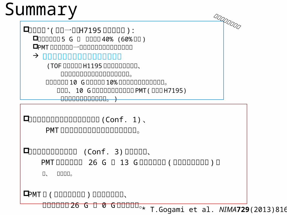
Summary先行研究 *( 径が一緒の H7195 のスタディ ):
管軸方向磁場 5 G ゲインが 40% (60% 減る ) PMT 光電面から第一ダノード付近が特に磁場に弱い 光電面付近で数ガウスに落としたい (TOF に使用する H1195 はゲインが良いので、 そこまでしなくてもいいかもしれません。 先行研究では 10 G でゲインが 10% になる事が分かっています。 つまり、 10 G くらいの環境下で普通の PMT( 例えば H7195) くらいのゲインがでるはず。 )
もともと考えていたシールド使用時 (Conf. 1) 、 PMT 光電面付近でシールドが無いのと同じ。
鉄板と鉄管の組み合わせ (Conf. 3) の場合には、 PMT 光電面付近で 26 G 13 G まで落とせる ( 鉄から遠いところ ) 。 が、 少し不安。
PMT の ( 磁気シールドの ) 真ん中付近では、 どの設定でも 26 G 0 G に落とせる。
本文に無いですが
* T.Gogami et al. NIMA729(2013)816-824

Backup
Sample lines for By plot
z
x
z
y