Embed Size (px)
Citation preview
5/11/2018 BA_3WL9111-0AT44-0AA0_Stand0511 - slidepdf.com
http://slidepdf.com/reader/full/ba3wl9111-0at44-0aa0stand0511 1/27
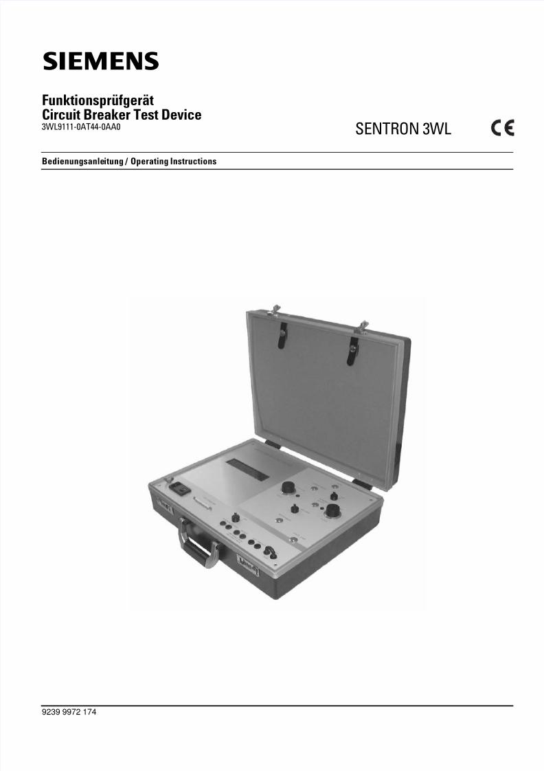
FunktionsprüfgerätCircuit Breaker Test Device3WL9111-0AT44-0AA0 SENTRON 3WL
9239 9972 174
Bedienungsanleitung / Operating Instructions
s
5/11/2018 BA_3WL9111-0AT44-0AA0_Stand0511 - slidepdf.com
http://slidepdf.com/reader/full/ba3wl9111-0at44-0aa0stand0511 2/27
Note
These instructions do not purport to cover all details or variations inequipment, nor to provide for every possible contingency to be metin connection with installation, operation or maintenance.
Should further information be desired or should particular problemsarise which are not covered sufficiently for the Purchaser’s purpo-ses, the matter should be referred to the local Siemens SalesOffice.
The contents of these oerating instructions shall not become part ofor modify any prior or existing agreement, commitment or relati-onship. The sales contract contains the entire obligations of Sie-mens. The warranty contained in the contract between the partiesis the sole warranty of Siemens. Any statements contained hereindo not create new warranties or modify the existing warranty.
SENTRON ® is a trademark of Siemens AG. The other designationsin this documentation can be trademarks. Use by third parties fortheir own purposes violates the owner's rights.
Symbols
Hinweis
Diese Bedienungsanleitung enthält aus Gründen der Übersichtlich-keit nicht sämtliche Detailinformationen zu allen Typen des Pro-dukts und kann auch nicht jeden denkbaren Fall der Aufstellung,des Betriebes oder der Instandhaltung berücksichtigen.
Sollten Sie weitere Informationen wünschen, oder sollten beson-dere Probleme auftreten, die in der Bedienungsanleitung nicht aus-führlich genug behandelt werden, können Sie die erforderlicheAuskunft über die örtliche Siemens-Niederlassung anfordern.
Außerdem weisen wir darauf hin, dass der Inhalt dieser Bedie-nungsanleitung nicht Teil einer früheren oder bestehenden Verein-barung, Zusage oder e ines Rechtsverhältnisses ist oder diesesabändern soll. Sämtliche Verpflichtungen von Siemens ergebensich aus dem jeweiligen Kaufvertrag, der auch die vollständige undalleingültige Gewährleistungsregelung enthält. Diese vertraglichenGewährleistungsbestimmungen werden durch die Ausführung die-ser Bedienungsanleitung weder erweitert noch beschränkt.
SENTRON ® ist eine eingetragene Marke der Siemens AG. Dieübrigen Bezeichnungen in dieser Dokumentation können Markensein, deren Benutzung durch Dritte für deren Zwecke die Rechteder Inhaber verletzt.
Symbole
Warnhinweis Warning
CE-Zeichen CE identification
5/11/2018 BA_3WL9111-0AT44-0AA0_Stand0511 - slidepdf.com
http://slidepdf.com/reader/full/ba3wl9111-0at44-0aa0stand0511 3/27
I
Inhalt
1 Lieferumfang 1-1
2 Technische Daten 2-1
3 Verwendung 3-1
4 Beschreibung der Bedienelemente 4-1
5 Bedienung 5-15.1 Zeitmessung 5-15.2 Bedienung des Prüfgerätes 5-15.3 Einstellen der Prüfströme L1, L2, L3 und N 5-25.4 Simulation des Stromes eines externen
Erdschlusswandlers (GF CT) 5-2
6 Prüfung des einstellbaren Überlastauslösers (L) 6-16.1 Prüfung des Grenzstromes 6-1
Unterer Grenzwert (1.05 x IR) 6-1Oberer Grenzwert (1.3 x IR) 6-1
6.2 Überprüfung der Überlast Kennlinie (L) 6-16.3 Prüfung des Trägheitsgrades 6-2
6.4 Prüfung des thermischen Gedächtnisses 6-27 Prüfung des kurzzeitverzögerten
Kurzschlussauslösers (S) 7-17.1 Prüfung des Ansprechstromes 7-1
Unterer Grenzwert 7-1Oberer Grenzwert 7-1
7.2 Prüfung der Verzögerungszeit 7-2Stromunabhängige Verzögerung, tsd = fix 7-2I²tsd-abhängige Verzögerung 7-2Zeitverkürzte Selektivitätssteuerung "ZSS" 7-3
Auslösung ohne Sperrsignal (am ZSS-Modul) 7-3Auslösung mit Sperrsignal (am ZSS-Modul) 7-3
8 Prüfung des unverzögerten Kurzschlussauslösers (I) 8-1
8.1 Prüfung des Ansprechstromes 8-1Unterer Grenzwert 8-1Oberer Grenzwert 8-1
8.2 Prüfung der Auslösezeit 8-1
9 Prüfung des Erdschlussauslösers (G) 9-19.1 Prüfung des Ansprechstromes bei der Messmethode
„Vektorielle Summenbildung“ 9-1Unterer Grenzwert 9-1Oberer Grenzwert 9-1Prüfung der Verzögerungszeit 9-1
Stromunabhängige Verzögerung, tg = fix 9-1I²tg-abhängige Verzögerung 9-2
Zeitverkürzte Selektivitätssteuerung "ZSS" 9-2Auslösung ohne Sperrsignal (am ZSS-Modul) 9-2
Auslösung mit Sperrsignal (am ZSS-Modul) 9-29.2 Prüfung der Erdschlussauslösung bei Anschluss
eines externen Erdschlussstromwandlers,Messmethode „Direkte Messung des Erdschlussstromes“ 9-3
Unterer Grenzwert 9-3Oberer Grenzwert 9-3Prüfung der Verzögerungszeit 9-3
Stromunabhängige Verzögerung, tg = fix 9-3I²tg-abhängige Verzögerung 9-4
Zeitverkürzte Selektivitätssteuerung "ZSS" 9-4Auslösung ohne Sperrsignal (am ZSS-Modul) 9-4Auslösung mit Sperrsignal (am ZSS-Modul) 9-4
10 Prüfung der Meldefunktionen 10-1
11 Prüfung des Auslösemagneten 11-1
Contents
1 Scope of Supply 1-1
2 Technical Data 2-1
3 Application 3-1
4 Description of the Control Elements 4-1
5 Operation 5-15.1 Time Measurement 5-15.2 Operating the Circuit Breaker Test Device 5-15.3 Setting the Test Currents L1, L2, L3 and N 5-25.4 Simulation of the Current of an External Ground-fault
Current Transformer (GF CT) 5-2
6 Testing the Adjustable Overload Release (L) 6-16.1 Testing the Limiting Overload Current 6-1
Lower limit value (1.05 x IR) 6-1Upper limit value (1.3 x IR) 6-1
6.2 Testing the Overload Characteristic Curve (L) 6-16.3 Testing the Time Lag Class 6-2
6.4 Testing the Thermal Memory 6-27 Testing the Short-time-delay
Short-circuit Release (S) 7-17.1 Testing the Tripping Current 7-1
Lower limit value 7-1Upper limit value 7-1
7.2 Testing the Delay Time 7-2Current-independent Delay, tsd = fixed 7-2I²tsd dependent delay 7-2Zone Selective Interlocking “ZSI” 7-3
Tripping without a Blocking Signal (on ZSI Module) 7-3Tripping with a Blocking Signal (on ZSI Module) 7-3
8 Testing the Instantaneous Short-circuit Release (I) 8-1
8.1 Testing the Tripping Current 8-1Lower limit value 8-1Upper limit value 8-1
8.2 Testing the Tripping Time 8-1
9 Testing the Ground-fault Release (G) 9-19.1 Testing the Tripping Current when using the
“Vectorial Summation” measuring method 9-1Lower limit value 9-1Upper Limit Value 9-1Testing the Delay Time 9-1
Current-independent Delay, tg = fixed 9-1I²tg Dependent Delay 9-2
Zone Selective Interlocking “ZSI” 9-2Tripping without a Blocking Signal (on ZSI Module) 9-2
Tripping with a Blocking Signal (on ZSI Module) 9-29.2 Testing the Ground-fault Release when an
External Ground-fault Current Transformer isConnected using the Measuring Method“Direct Measurement of the Ground-fault Current” 9-3
Lower Limit Value 9-3Upper Limit Value 9-3Testing the Delay Time 9-3
Current-independent delay, tg = fixed 9-3I²tg Dependent Delay 9-4
Zone Selective Interlocking “ZSI” 9-4Tripping without a Blocking Signal (on ZSI Module) 9-4Tripping with a Blocking Signal (on ZSI Module) 9-4
10 Testing the Signaling Functions 10-111 Testing the Tripping Solenoid 11-1

5/11/2018 BA_3WL9111-0AT44-0AA0_Stand0511 - slidepdf.com
http://slidepdf.com/reader/full/ba3wl9111-0at44-0aa0stand0511 4/27
II
12 Abkürzungen 12-1
13 Index 13-1
12 Abbreviations 12-1
13 Index 13-1
5/11/2018 BA_3WL9111-0AT44-0AA0_Stand0511 - slidepdf.com
http://slidepdf.com/reader/full/ba3wl9111-0at44-0aa0stand0511 5/27
1 – 1
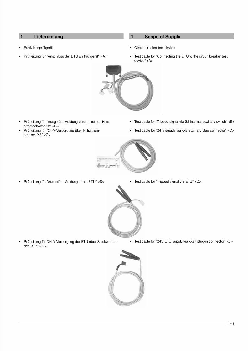
1 Scope of Supply
• Circuit breaker test device
• Test cable for “Connecting the ETU to the circuit breaker test
device” <A>
• Test cable for “Tripped signal via S2 internal auxiliary switch” <B>
• Test cable for “24 V supply via -X8 auxiliary plug connector” <C>
• Test cable for “Tripped signal via ETU” <D>
• Test cable for “24V ETU supply via -X27 plug-in connector” <E>
1 Lieferumfang
• Funktionsprüfgerät
• Prüfleitung für "Anschluss der ETU an Prüfgerät" <A>
• Prüfleitung für "Ausgelöst-Meldung durch internen Hilfs-stromschalter S2" <B>• Prüfleitung für "24-V-Versorgung über Hilfsstrom-
stecker -X8" <C>
• Prüfleitung für "Ausgelöst-Meldung durch ETU" <D>
• Prüfleitung für "24-V-Versorgung der ETU über Steckverbin-der -X27" <E>
5/11/2018 BA_3WL9111-0AT44-0AA0_Stand0511 - slidepdf.com
http://slidepdf.com/reader/full/ba3wl9111-0at44-0aa0stand0511 6/27
1 – 2
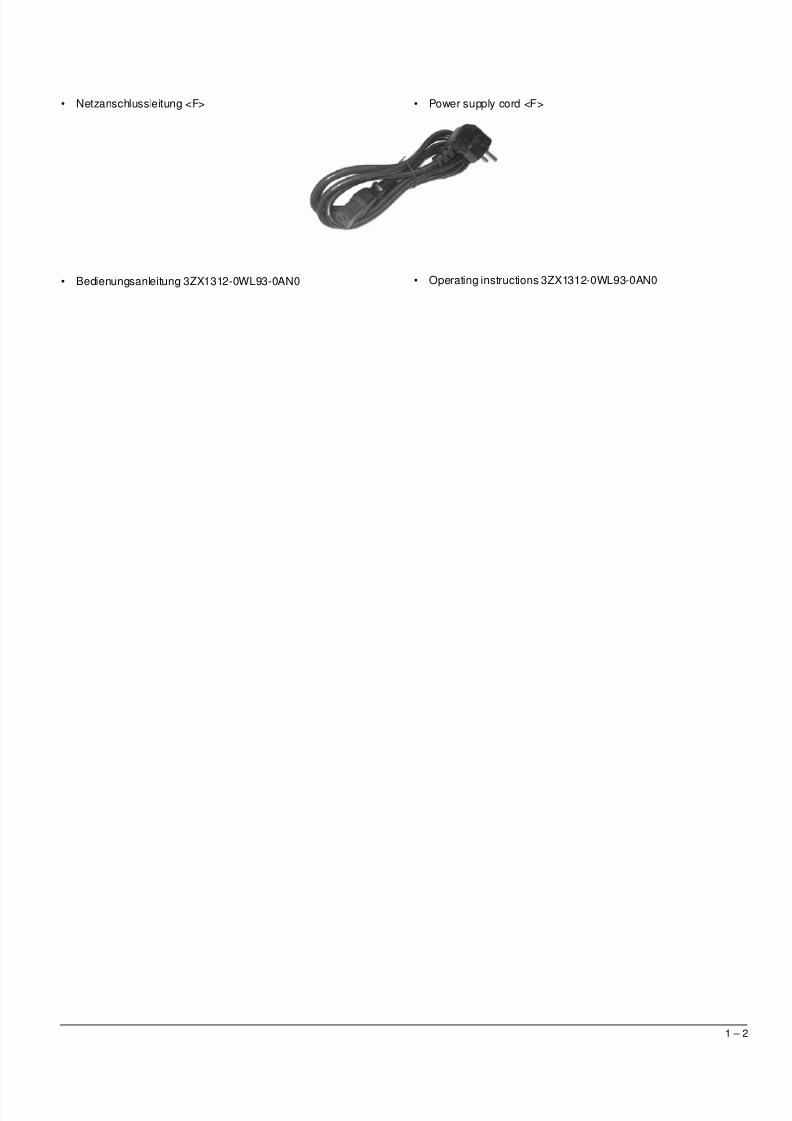
• Netzanschlussleitung <F>
• Bedienungsanleitung 3ZX1312-0WL93-0AN0
• Power supply cord <F>
• Operating instructions 3ZX1312-0WL93-0AN0
5/11/2018 BA_3WL9111-0AT44-0AA0_Stand0511 - slidepdf.com
http://slidepdf.com/reader/full/ba3wl9111-0at44-0aa0stand0511 7/27
2 – 1
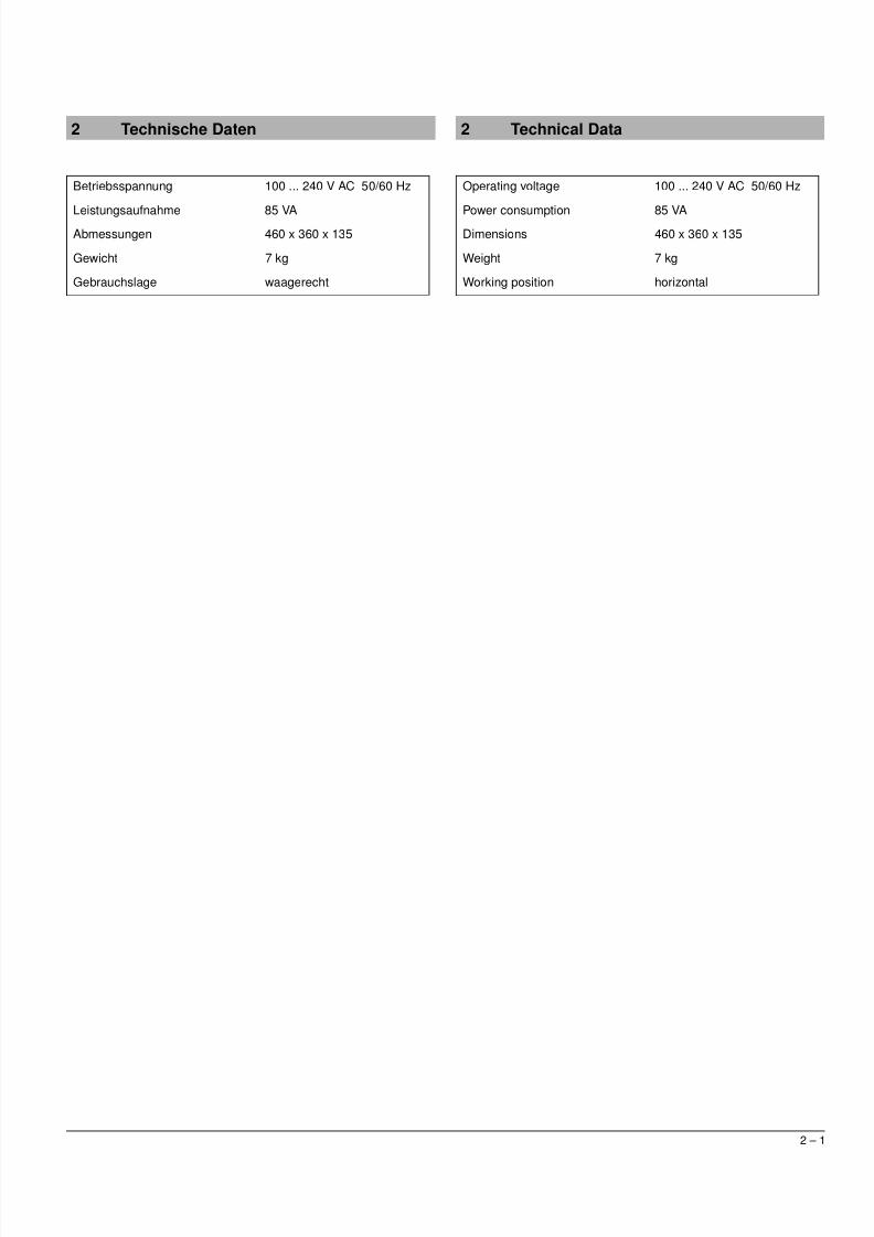
2 Technical Data
Operating voltage 100 ... 240 V AC 50/60 Hz
Power consumption 85 VADimensions 460 x 360 x 135
Weight 7 kg
Working position horizontal
2 Technische Daten
Betriebsspannung 100 ... 240 V AC 50/60 Hz
Leistungsaufnahme 85 VAAbmessungen 460 x 360 x 135
Gewicht 7 kg
Gebrauchslage waagerecht
5/11/2018 BA_3WL9111-0AT44-0AA0_Stand0511 - slidepdf.com
http://slidepdf.com/reader/full/ba3wl9111-0at44-0aa0stand0511 8/27
3 – 1
3 Application
The 3WL9111-0AT44-0AA0 circuit breaker test device is used totest the functions of the SENTRON 3WL low-voltage circuit breaker.
For the ETU15B, ETU25B, ETU27B, ETU45B, ETU55B andETU76B overcurrent releases of the 3WL circuit breaker, the circuitbreaker test device can be used to:
• Measure the operating currents and tripping times.• Check the protection functions for the three phases and
the neutral conductor.• Verify the function of the tripping solenoid.• Check the function of the ground-fault protection.• Measure the opening time of the circuit breaker and to• Check the trip causes.
The circuit breaker test device generates either a one or two-phasetest voltage that reproduces the output signal of the current sensors(Rogowski coils). The test voltage is fed into the incoming circuit of
the current measuring device (L1, L2, L3 and N) as either one-phase or two-phase (180°phase shift) voltage. The level of thesimulated test current is infinitely variable from zero to 150 kA infour ranges.
Note: A two-phase test voltage infeed is required if the ground faultrelease is not deactivated.
The setting range of the test current allows the characteristic curvesof all electronic overcurrent releases (ETU = Electronic Trip Unit) tobe checked. Therefore, the device does not normally require thesettings of the electronic overcurrent releases to be altered.
This circuit breaker test device is equipped with a display for settingthe required test current.
The circuit breaker test device takes the frequency dependency ofthe test voltage of 50 and 60 Hz appliances into consideration. Thetripping and opening times are also indicated on the test devicedisplay. For carrying out the tests, the overcurrent release can eitherbe mounted in the circuit breaker or, in special cases, it can betested separately. However, the release has to be mounted in thecircuit breaker for testing the tripping solenoid and the openingtimes of the circuit breaker.
3 Verwendung
Das Prüfgerät 3WL9111-0AT44-0AA0 dient zur Überprüfung derFunktionen des Niederspannungsleistungsschalters
SENTRON 3WL.Mit dem Funktionsprüfgerät können bei den Elektronischen Über-stromauslösern ETU15B, ETU25B, ETU27B, ETU45B, ETU55Bund ETU76B des Leistungsschalters 3WL
• Ansprechströme und Auslösezeiten gemessen werden.• die Schutzfunktionen für die drei Phasen und den Neutral-
leiter überprüft werden.• die Funktion des Auslösemagneten nachgewiesen wer-
den.• die Erdschlussschutzfunktion geprüft werden.• die Öffnungszeit des Leistungsschalters gemessen wer-
den und die• Auslösegründe überprüft werden.
Das Prüfgerät erzeugt wahlweise eine ein- oder zweiphasige Prüf-spannung, die das Ausgangssignal der Stromsensoren (Rogowski-Spulen) nachbildet. Die Prüfspannung wird über die Prüfbuchsewahlweise in die Eingangskreise der Stromerfassung (L1, L2, L3und N) ein- oder zweiphasig (180° Phasenverschiebung) einge-speist. Die Höhe des simulierten Prüfstromes ist von Null bis 150 kAin vier Bereichen stufenlos einstellbar.
Hinweis: Eine zweiphasige Einspeisung der Prüfspannungen isterforderlich, wenn der Erdschlussauslöser nicht deaktiviert ist.
Der Einstellbereich des Prüfstromes erlaubt die Überprüfung allerKennlinienfelder der Elektronischen Überstromauslöser (ETU =Electronic Trip Unit). Das Gerät verlangt daher im Allgemeinenkeine Veränderung der Einstellungen der elektronischen Über-
stromauslöser.Das Prüfgerät enthält ein Display zur Einstellung des erforderlichenPrüfstromes.
Das Gerät berücksichtigt die Frequenzabhängigkeit der Prüfspan-nung bei 50- und 60-Hz-Anwendungen. Die Auslöse- bzw. Öff-nungszeiten werden ebenfalls auf dem Display des Prüfgerätesangezeigt. Für die Prüfungen kann der Überstromauslöser entwe-der im Leistungsschalter eingebaut sein oder in Sonderfällen sepa-rat geprüft werden. Nur für die Prüfung des Auslösemagneten undder Öffnungszeit des Leistungsschalters muss der Auslöser im Lei-stungsschalter eingebaut sein.
ACHTUNG NOTICE
Zur Ereichung der angegebenen Genauigkeiten ist eine Vor-wärmzeit von 15 Minuten erforderlich.
15 preheating is necessary, in order to ensure the specifiedexactitudes.
5/11/2018 BA_3WL9111-0AT44-0AA0_Stand0511 - slidepdf.com
http://slidepdf.com/reader/full/ba3wl9111-0at44-0aa0stand0511 9/27
4 – 1
4 Description of the Control Elements
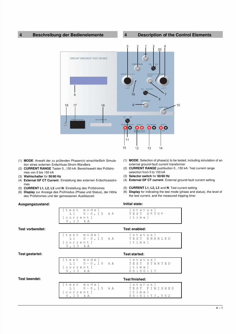
(1) MODE: Selection of phase(s) to be tested, including simulation of anexternal ground-fault current transformer
(2) CURRENT RANGE pushbutton 0...150 kA: Test current rangeselection from 0 to 150 kA
(3) Selector switch for 50/60 Hz(4) External GF CT current: External ground-fault current setting
(5) CURRENT L1, L2, L3 and N: Test current setting(6) Display for indicating the test mode (phase and status), the level of
the test current, and the measured tripping time:
Initial state:
Test enabled:
Test started:
Test finished:
4 Beschreibung der Bedienelemente
(1) MODE: Anwahl der zu prüfenden Phasen(n) einschließlich Simula-tion eines externen Erdschluss-Strom-Wandlers
(2) CURRENT RANGE Taster 0...150 kA: Bereichswahl des Prüfstro-mes von 0 bis 150 kA
(3) Wahlschalter für 50/60 Hz(4) External GF CT Current: Einstellung des externen Erdschlussstro-
mes(5) CURRENT L1, L2, L3 und N: Einstellung des Prüfstromes(6) Display zur Anzeige des Prüfmodus (Phase und Status), der Höhe
des Prüfstromes und der gemessenen Auslösezeit:
Ausgangszustand:
Test vorbereitet:
Test gestartet:
Test beendet:
5 4
20
312
10
7
8
9
19
18 1617
6
15
11
12 13 14
[ t e s t m o d e ] [ s t a t u s ]
L 1 0 - 0 , 1 5 k A T E S T S E T U P
[ c u r r e n t ] [ t i m e ]
0 , 1 3 k A
[ t e s t m o d e ] [ s t a t u s ]
L 1 0 - 0 , 1 5 k A T E S T E N A B L E D
[ c u r r e n t ] [ t i m e ]
0 , 1 3 k A
[ t e s t m o d e ] [ s t a t u s ]
L 1 0 - 0 , 1 5 k A T E S T S T A R T E D
[ c u r r e n t ] [ t i m e ]
0 , 1 3 k A 0 0 : 0 0 : 1 3
[ t e s t m o d e ] [ s t a t u s ]
L 1 0 - 0 , 1 5 k A T E S T F I N I S H E D
[ c u r r e n t ] [ t i m e ]
0 , 1 3 k A 0 0 : 0 1 : 5 3 , 5 6 2
5/11/2018 BA_3WL9111-0AT44-0AA0_Stand0511 - slidepdf.com
http://slidepdf.com/reader/full/ba3wl9111-0at44-0aa0stand0511 10/27
4 – 2
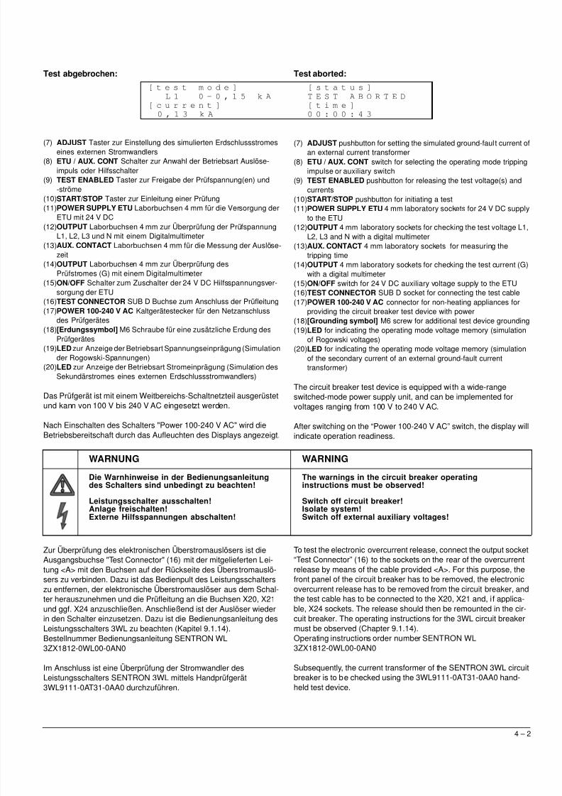
Test abgebrochen:
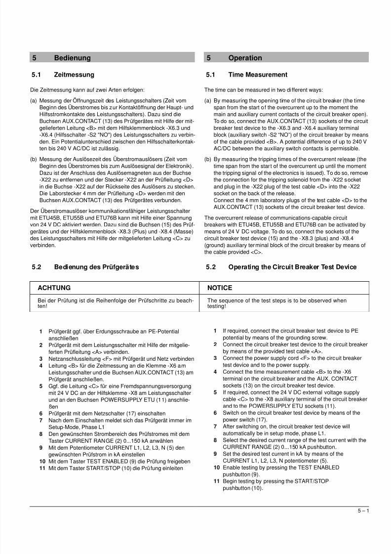
(7) ADJUST Taster zur Einstellung des simulierten Erdschlussstromeseines externen Stromwandlers
(8) ETU / AUX. CONT Schalter zur Anwahl der Betriebsart Auslöse-impuls oder Hilfsschalter
(9) TEST ENABLED Taster zur Freigabe der Prüfspannung(en) und-ströme
(10)START/STOP Taster zur Einleitung einer Prüfung(11)POWER SUPPLY ETU Laborbuchsen 4 mm für die Versorgung der
ETU mit 24 V DC(12)OUTPUT Laborbuchsen 4 mm zur Überprüfung der Prüfspannung
L1, L2, L3 und N mit einem Digitalmultimeter(13)AUX. CONTACT Laborbuchsen 4 mm für die Messung der Auslöse-
zeit(14)OUTPUT Laborbuchsen 4 mm zur Überprüfung des
Prüfstromes (G) mit einem Digitalmultimeter(15)ON/OFF Schalter zum Zuschalter der 24 V DC Hilfsspannungsver-sorgung der ETU
(16)TEST CONNECTOR SUB D Buchse zum Anschluss der Prüfleitung(17)POWER 100-240 V AC Kaltgerätestecker für den Netzanschluss
des Prüfgerätes(18)[Erdungssymbol] M6 Schraube für eine zusätzliche Erdung des
Prüfgerätes(19)LED zur Anzeige der Betriebsart Spannungseinprägung (Simulation
der Rogowski-Spannungen)(20)LED zur Anzeige der Betriebsart Stromeinprägung (Simulation des
Sekundärstromes eines externen Erdschlussstromwandlers)
Das Prüfgerät ist mit einem Weitbereichs-Schaltnetzteil ausgerüstetund kann von 100 V bis 240 V AC eingesetzt werden.
Nach Einschalten des Schalters "Power 100-240 V AC" wird dieBetriebsbereitschaft durch das Aufleuchten des Displays angezeigt.
Zur Überprüfung des elektronischen Überstromauslösers ist dieAusgangsbuchse "Test Connector" (16) mit der mitgelieferten Lei-tung <A> mit den Buchsen auf der Rückseite des Überstromauslö-sers zu verbinden. Dazu ist das Bedienpult des Leistungsschalterszu entfernen, der elektronische Überstromauslöser aus dem Schal-ter herauszunehmen und die Prüfleitung an die Buchsen X20, X21und ggf. X24 anzuschließen. Anschließend ist der Auslöser wiederin den Schalter einzusetzen. Dazu ist die Bedienungsanleitung desLeistungsschalters 3WL zu beachten (Kapitel 9.1.14).Bestellnummer Bedienungsanleitung SENTRON WL3ZX1812-0WL00-0AN0
Im Anschluss ist eine Überprüfung der Stromwandler desLeistungsschalters SENTRON 3WL mittels Handprüfgerät3WL9111-0AT31-0AA0 durchzuführen.
WARNUNG WARNING
Die Warnhinweise in der Bedienungsanleitungdes Schalters sind unbedingt zu beachten!
Leistungsschalter ausschalten!Anlage freischalten!Externe Hilfsspannungen abschalten!
The warnings in the circuit breaker operatinginstructions must be observed!
Switch off circuit breaker!Isolate system!Switch off external auxiliary voltages!
[ t e s t m o d e ] [ s t a t u s ]
L 1 0 - 0 , 1 5 k A T E S T A B O R T E D
[ c u r r e n t ] [ t i m e ]
0 , 1 3 k A 0 0 : 0 0 : 4 3
Test aborted:
(7) ADJUST pushbutton for setting the simulated ground-fault current ofan external current transformer
(8) ETU / AUX. CONT switch for selecting the operating mode trippingimpulse or auxiliary switch
(9) TEST ENABLED pushbutton for releasing the test voltage(s) andcurrents
(10)START/STOP pushbutton for initiating a test(11)POWER SUPPLY ETU 4 mm laboratory sockets for 24 V DC supply
to the ETU(12)OUTPUT 4 mm laboratory sockets for checking the test voltage L1,
L2, L3 and N with a digital multimeter(13)AUX. CONTACT 4 mm laboratory sockets for measuring the
tripping time(14)OUTPUT 4 mm laboratory sockets for checking the test current (G)
with a digital multimeter(15)ON/OFF switch for 24 V DC auxiliary voltage supply to the ETU(16)TEST CONNECTOR SUB D socket for connecting the test cable(17)POWER 100-240 V AC connector for non-heating appliances for
providing the circuit breaker test device with power(18)[Grounding symbol] M6 screw for additional test device grounding(19)LED for indicating the operating mode voltage memory (simulation
of Rogowski voltages)(20)LED for indicating the operating mode voltage memory (simulation
of the secondary current of an external ground-fault currenttransformer)
The circuit breaker test device is equipped with a wide-rangeswitched-mode power supply unit, and can be implemented forvoltages ranging from 100 V to 240 V AC.
After switching on the “Power 100-240 V AC” switch, the display willindicate operation readiness.
To test the electronic overcurrent release, connect the output socket“Test Connector” (16) to the sockets on the rear of the overcurrentrelease by means of the cable provided <A>. For this purpose, thefront panel of the circuit breaker has to be removed, the electronicovercurrent release has to be removed from the circuit breaker, andthe test cable has to be connected to the X20, X21 and, i f applica-ble, X24 sockets. The release should then be remounted in the cir-cuit breaker. The operating instructions for the 3WL circuit breakermust be observed (Chapter 9.1.14).Operating instructions order number SENTRON WL3ZX1812-0WL00-0AN0
Subsequently, the current transformer of the SENTRON 3WL circuitbreaker is to be checked using the 3WL9111-0AT31-0AA0 hand-held test device.
5/11/2018 BA_3WL9111-0AT44-0AA0_Stand0511 - slidepdf.com
http://slidepdf.com/reader/full/ba3wl9111-0at44-0aa0stand0511 11/27
5 – 1
5 Operation
5.1 Time Measurement
The time can be measured in two different ways:
(a) By measuring the opening time of the circuit breaker (the timespan from the start of the overcurrent up to the moment themain and auxiliary current contacts of the circuit breaker open).To do so, connect the AUX.CONTACT (13) sockets of the circuitbreaker test device to the -X6.3 and -X6.4 auxiliary terminalblock (auxiliary switch -S2 “NO”) of the circuit breaker by meansof the cable provided <B>. A potential difference of up to 240 VAC/DC between the auxiliary switch contacts is permissible.
(b) By measuring the tripping times of the overcurrent release (thetime span from the start of the overcurrent up until the momentthe tripping signal of the electronics is issued). To do so, removethe connection for the tripping solenoid from the -X22 socketand plug in the -X22 plug of the test cable <D> into the -X22
socket on the back of the release.Connect the 4 mm laboratory plugs of the test cable <D> to theAUX.CONTACT (13) sockets of the circuit breaker test device.
The overcurrent release of communications-capable circuitbreakers with ETU45B, ETU55B and ETU76B can be activated bymeans of 24 V DC voltage. To do so, connect the sockets of thecircuit breaker test device (15) and the -X8.3 (plus) and -X8.4(ground) auxiliary terminal block of the circuit breaker by means ofthe cable provided <C>.
5.2 Operating the Circuit Breaker Test Device
1 If required, connect the circuit breaker test device to PEpotential by means of the grounding screw.
2 Connect the circuit breaker test device to the circuit breakerby means of the provided test cable <A>.
3 Connect the power supply cord <F> to the circuit breakertest device and to the power supply.
4 Connect the time measurement cable <B> to the -X6terminal on the circuit breaker and the AUX. CONTACT
sockets (13) on the circuit breaker test device.5 If required, connect the 24 V DC external voltage supply
cable <C> to the -X8 auxiliary terminal of the circuit breakerand to the POWERSUPPLY ETU sockets (11).
6 Switch on the circuit breaker test device by means of thepower switch (17).
7 After switching on, the circuit breaker test device willautomatically be in setup mode, phase L1.
8 Select the desired current range of the test current with theCURRENT RANGE (2) 0...150 kA pushbutton.
9 Set the desired test current in kA by means of theCURRENT L1, L2, L3, N potentiometer (5).
10 Enable testing by pressing the TEST ENABLEDpushbutton (9).
11 Begin testing by pressing the START/STOPpushbutton (10).
5 Bedienung
5.1 Zeitmessung
Die Zeitmessung kann auf zwei Arten erfolgen:
(a) Messung der Öffnungszeit des Leistungsschalters (Zeit vomBeginn des Überstromes bis zur Kontaktöffnung der Haupt- undHilfsstromkontakte des Leistungsschalters). Dazu sind dieBuchsen AUX.CONTACT (13) des Prüfgerätes mit Hilfe der mit-gelieferten Leitung <B> mit dem Hilfsklemmenblock -X6.3 und-X6.4 (Hilfsschalter -S2 "NO") des Leistungsschalters zu verbin-den. Ein Potentialunterschied zwischen den Hilfsschalterkontak-ten bis 240 V AC/DC ist zulässig.
(b) Messung der Auslösezeit des Überstromauslösers (Zeit vomBeginn des Überstromes bis zum Auslösesignal der Elektronik).Dazu ist der Anschluss des Auslösemagneten aus der Buchse-X22 zu entfernen und der Stecker -X22 an der Prüfleitung <D>in die Buchse -X22 auf der Rückseite des Auslösers zu stecken.
Die Laborstecker 4 mm der Prüfleitung <D> werden mit denBuchsen AUX.CONTACT (13) des Prüfgerätes verbunden.
Der Überstromauslöser kommunikationsfähiger Leistungsschaltermit ETU45B, ETU55B und ETU76B kann mit Hilfe einer Spannungvon 24 V DC aktiviert werden. Dazu sind die Buchsen (15) des Prüf-gerätes und der Hilfsklemmenblock -X8.3 (Plus) und -X8.4 (Masse)des Leistungsschalters mit Hilfe der mitgelieferten Leitung <C> zuverbinden.
5.2 Bedienung des Prüfgerätes
1 Prüfgerät ggf. über Erdungsschraube an PE-Potentialanschließen
2 Prüfgerät mit dem Leistungsschalter mit Hilfe der mitgelie-ferten Prüfleitung <A> verbinden.
3 Netzanschlussleitung <F> mit Prüfgerät und Netz verbinden4 Leitung <B> für die Zeitmessung an die Klemme -X6 am
Leistungsschalter und die Buchsen AUX.CONTACT (13) amPrüfgerät anschließen.
5 Ggf. die Leitung <C> für eine Fremdspannungsversorgungmit 24 V DC an der Hilfsklemme -X8 am Leistungsschalterund an den Buchsen POWERSUPPLY ETU (11) anschlie-ßen
6 Prüfgerät mit dem Netzschalter (17) einschalten7 Nach dem Einschalten meldet sich das Prüfgerät immer im
Setup-Mode, Phase L18 Den gewünschten Strombereich des Prüfstromes mit dem
Taster CURRENT RANGE (2) 0...150 kA anwählen9 Mit dem Potentiometer CURRENT L1, L2, L3, N (5) den
gewünschten Prüfstrom in kA einstellen10 Mit dem Taster TEST ENABLED (9) die Prüfung freigeben11 Mit dem Taster START/STOP (10) die Prüfung einleiten
ACHTUNG NOTICEBei der Prüfung ist die Reihenfolge der Prüfschritte zu beach-ten!
The sequence of the test steps is to be observed whentesting!
5/11/2018 BA_3WL9111-0AT44-0AA0_Stand0511 - slidepdf.com
http://slidepdf.com/reader/full/ba3wl9111-0at44-0aa0stand0511 12/27
5 – 2
12 Nach einer Auslösung des Schalters wird die Prüfzeit imDisplay angezeigt. Ggf. Prüfung durch Betätigen der TasteSTART/STOP (10) vorzeitig beenden
13 Kontrolle, ob die richtige Schutzart ausgelöst hat durchDrücken des Tasters QUERY an dem zu prüfenden elektro-nischen Überstromauslöser. Prüfung, ob die aufleuchtendeLED am Prüfling den richtigen Auslösegrund anzeigt.Mit der Taste MODE (1) die nächste Prüfung durch Anwahlder Phase(n) vorbereiten.Ggf. mit der Taste TEST ENABLED (9) und Betätigen derTaste START/STOP (10) die Prüfung wiederholen
Bei der Überprüfung der Erdschlussschutzfunktion durch Simula-tion eines externen Stromwandlers wird sinngemäß verfahren. DieEinstellung der Betriebsart (entspricht dem Sekundärstrom desexternen Stromwandlers zur Erdschlusserfassung) mit der TasteMODE (1) vornehmen.
Bei gedrückter Taste ADJUST (7) und mit dem PotentiometerEXTERNAL GF CT (4) den Prüfstrom in Ampere einstellen(1 A entspricht dabei einem Erdschlussstrom von 1200 A).
5.3 Einstellen der Prüfströme L1, L2, L3 und N
Die Höhe des erforderlichen Prüfstromes kann mit dem TasterCURRENT RANGE (2) in den Bereichen 0...150 A / 0…1.5 kA / 0…15 kA / 0…150 kA vorgewählt werden.Im Display wird der gewählte Bereich angezeigt
Mit Hilfe des Potentiometers CURRENT L1, L2, L3, N (5) kann derPrüfstrom eingestellt werden. Die Anzeige des gewählten Prüfstro-mes erfolgt auf dem Display (6) des Prüfgerätes in kA.Die Netzfrequenz kann mit dem Schalter 50/60 Hz gewählt werden.
Der Taster TEST ENABLED (9) gestattet es abwechselnd die
Betriebsarten TEST SETUP und TEST ENABLED zu wählen.Zum Starten der Prüfung wird der Taster START/STOP (10) betä-tigt. Entsprechend der gewählten Triggerart wird der Timer desPrüfgerätes von einem Hilfsschalterkontakt oder dem Auslöseim-puls des elektronischen Auslösers gestoppt.Die gemessene Zeit wird auf dem Display angezeigt.
Der Prüfvorgang kann jederzeit mit der START/STOP-Taste (10)unterbrochen werden.
5.4 Simulation des Stromes eines externenErdschlusswandlers (GF CT)
Zur Prüfung der Betriebsart Erdschlussüberwachung mit einemexternen Stromwandler wird mit dem Taster MODE (1) die Betriebs-art Erdschluss GF gewählt.
Die Einstellung des Prüfstromes (entspricht dem Sekundärstromdes externen Stromwandlers zur Erdschlusserfassung) mit demTaster ADJUST (7) und dem Potentiometer EXTERNAL GF CT (4)vornehmen.
12 The test period is indicated on the display when the circuitbreaker trips. If desired, testing can be prematurely stoppedby pressing the START/STOP pushbutton (10).
13 Whether or not the correct degree of protection has beentripped can be checked by pressing the QUERY pushbuttonon the electronic overcurrent release that is being tested.Check whether the lit LED on the device being tested isdisplaying the correct trip cause.The next test can be enabled by pressing the MODEpushbutton (1) to select the phase(s).If required, testing can be repeated by pressing the TESTENABLED (9) and START/STOP (10) pushbuttons.
The ground-fault protection function can be tested in a similarmanner by simulating an external current transformer. Theoperating mode (equivalent to the secondary current of an externalcurrent transformer for ground fault detection) is set by means of theMODE pushbutton (1).
Set the test current in amperes by continually pressing the ADJUST(7) pushbutton and setting the EXTERNAL GF CT potentiometer (4)(1 A is equivalent to a ground-fault current of 1,200 A).
5.3 Setting the Test Currents L1, L2, L3 and N
The level of the required test current can be pre-selected within thefollowing ranges 0...150 A / 0…1.5 kA / 0…15 kA / 0…150 kA bymeans of the CURRENT RANGE pushbutton (2).The selected range is indicated in the display.
The test current can be set by means of the CURRENT L1, L2, L3,N potentiometer (5). The circuit breaker test device display (6)indicates the selected test current in kA.The network frequency can be selected by means of the 50/60 Hzswitch.
The TEST ENABLED pushbutton (9) permits alternating betweenthe TEST SETUP and TEST ENABLED operating modes.
Testing is started by pressing the START/STOP pushbutton (10).Depending on the selected trigger type, the timer of the circuitbreaker test device is stopped either by an auxiliary switch contactor by the tripping impulse of the electronic release.The measured time is shown on the display.
Testing can be interrupted at any time by pressing the START/STOPpushbutton (10).
5.4 Simulation of the Current of an ExternalGround-fault Current Transformer (GF CT)
To test the operating mode Ground-fault Monitoring with an externalcurrent transformer, select the operating mode Ground Fault GF bymeans of the MODE pushbutton (1).
To set the test current (the equivalent of the secondary current ofthe external current transformer for ground fault detection), use theADJUST pushbutton (7) and the EXTERNAL GF CTpotentiometer (4).
5/11/2018 BA_3WL9111-0AT44-0AA0_Stand0511 - slidepdf.com
http://slidepdf.com/reader/full/ba3wl9111-0at44-0aa0stand0511 13/27
6 – 1
6 Prüfung des einstellbarenÜberlastauslösers (L)
Bei diesen Prüfungen muß darauf geachtet werden, daß die einge-stellten Prüfströme nicht größer sind als die Ansprechwerte für die
Schutzarten S, I und G.
6.1 Prüfung des Grenzstromes
Die Auswahl der zu prüfenden Phase erfolgt über MODE (1).
6.1.1 Unterer Grenzwert (1.05 x IR)
Prüfstrom gemäß Ip = IR *1.05 einstellenIp = PrüfstromIR = Einstellstrom des Leistungsschalters
Bei diesem Strom darf der Überstromauslöser gemäß EN60947-2/ IEC 60947-2 innerhalb von 2 Stunden nicht auslösen.
Die Prüfung kann mit dem Taster START/STOP (10) abgebrochenwerden.
6.1.2 Oberer Grenzwert (1.3 x IR)
Prüfstrom gemäß Ip = IR *1.3 einstellenIp = PrüfstromIR = Einstellstrom des Leistungsschalters
Bei diesem Strom muss der Überstromauslöser gemäß EN60947-2/ IEC 60947-2 innerhalb von 2 Stunden auslösen.
6.2 Überprüfung der Überlast Kennlinie (L)
Prüfstrom einstellen.
Bei dem gewählten Prüfstrom muss der Überstromauslöser nach:
ta max = tR * [6 / (I / IR)]2 für die I2t-Kennline
ta min = 0.8 * ta max
ta max = tR * [6 / (I / IR)]4 für die I4t-Kennline
ta min = 0.6 * ta max
auslösen.
Die Prüfung in den Phasen L2, L3 und ggf. N wiederholen. Dabei istzu beachten, dass bei der Einstellung IN = 0.5 * In der Prüfstrom0.5 * I / In beträgt.
Achtung: Bei den Auslösern ETU15B, ETU25B und ETU27B ist derTrägheitsgrad tR der Überlastauslösung fest auf 10 s eingestellt.
6 Testing the Adjustable OverloadRelease (L)
When carrying out this test, ensure that the set test currents are notgreater than the response thresholds for the degrees of protection
S, I and G.
6.1 Testing the Limiting Overload Current
The phases to be tested are selected by means of MODE (1).
6.1.1 Lower limit value (1.05 x IR)
Set test current according to Ip = IR *1.05Ip = test currentIR = circuit breaker setting current
In accordance with EN60947-2/IEC 60947-2, the overcurrentrelease may not trip within 2 hours when this current is applied.
Testing can be aborted by pressing the START/STOP (10)pushbutton.
6.1.2 Upper limit value (1.3 x IR)
Set test current according to Ip = IR *1.3Ip = test currentIR = circuit breaker setting current
In accordance with EN60947-2/IEC 60947-2, the overcurrentrelease may not trip within 2 hours when this current is applied.
6.2 Testing the Overload Characteristic Curve (L)
Set the test current.
For the selected test current, the overcurrent release must trip after:
ta max = tR * [6 / (I / IR)]2 for the I2t characteristic curve
ta min = 0.8 * ta max
ta max = tR * [6 / (I / IR)]4 for the I4t characteristic curve
ta min = 0.6 * ta max
Repeat the test in phases L2, L3 and, if required, N. Ensure that inthe case of the setting IN = 0.5 * In, the test current is 0.5 * I / In.
Warning: In the case of the ETU15B, ETU25B and ETU27B
releases, the time lag class tR of the overload release is fixed at10 s.
5/11/2018 BA_3WL9111-0AT44-0AA0_Stand0511 - slidepdf.com
http://slidepdf.com/reader/full/ba3wl9111-0at44-0aa0stand0511 14/27
6 – 2
6.3 Testing the Time Lag Class
Select phase L1 by means of the MODE pushbutton (1).
Set the test current according to Ip = 6 * IR.Ip = test currentIR = setting current 0.4 ...1.0 * In
Start testing by pressing the START/STOP pushbutton (10).
When testing ETU15B, ETU25B or ETU27B releases, themeasured tripping time must be between 8 and 10 seconds.
For all other releases, the measured tripping time must be the sameas the time lag class tR +0 / -20 % that is set on the release (settingI2t) or tR +0 / -40% (setting I
4t).
After testing in conducting path L1, repeat the test in conductingpaths L2, L3 and, if required, conducting path N. In the case of thesetting IN = 0.5 * In, ensure that the test current is 0.5* I / In.
6.4 Testing the Thermal Memory
This test is used when the thermal memory (MEMORY) of the ETUis switched on.
Thermal memory testing can be carried out in any phase.
- Deactivate the external power supply (15).- Select the phase by means of the MODE pushbutton (1).- Set the test current as described in 5.3 Setting the Test
Currents L1, L2, L3 and N.- Enable testing by pressing the TEST ENABLED
pushbutton (9).- Start testing by pressing the START/STOP
pushbutton (10).- After successful tripping, start the test procedure againimmediately (pushbutton (9), pushbutton (10)).
The tripping time of the second tr ipping event should be at least 5%shorter than that of the first tr ipping event. If the memory is switchedoff, all tests will result in the entire tripping time:
ta max = tR * [6 / (I / IR)]2 for the I2t characteristic curve
ta max = tR * [6 / (I / IR)]4 for the I4t characteristic curve
6.3 Prüfung des Trägheitsgrades
Mit Taster MODE (1) Phase L1 anwählen.
Prüfstrom gemäß Ip = 6 * IR einstellen.Ip = PrüfstromIR = Einstellstrom 0,4 ...1,0 * In
Prüfvorgang mit Taster START/STOP (10) einleiten
Bei Prüfung eines Auslösers ETU15B, ETU25B oder ETU27B mussdie gemessene Auslösezeit zwischen 8 und 10 s liegen.
Bei allen anderen Auslösern muss die gemessene Auslösezeitgleich dem am Auslöser eingestellten Trägheitsgrad tR +0 / -20 %betragen (Einstellung I
2t) oder tR +0 / -40 % betragen (EinstellungI4t).
Nach der Prüfung in der Strombahn L1 ist die Prüfung in den Strom-bahnen L2, L3 und ggf. der Strombahn N zu wiederholen. Dabei istzu beachten, dass bei der Einstellung IN = 0.5 * In der Prüfstrom0.5* I / In beträgt.
6.4 Prüfung des thermischen Gedächtnisses
Diese Prüfung wird angewendet, wenn das thermische Gedächtnisder ETU (MEMORY) eingeschaltet ist.
Die Prüfung des thermischen Gedächtnisses kann in einer beliebi-gen Phase durchgeführt werden.
- Fremdversorgung deaktivieren (15)- Mit dem Taster MODE (1) die Phase anwählen- Prüfstrom wie unter 5.3 Einstellen der Prüfströme L1, L2,
L3 und N beschrieben einstellen- Prüfung vorbereiten mit Taster TEST ENABLED (9)- Prüfvorgang mit Taster START/STOP (10) einleiten
- Nach erfolgter Auslösung Prüfvorgang sofort erneut star-ten (Taster (9), Taster (10)).
Die Auslösezeit der zweiten Auslösung muss mindestens 5% klei-ner sein als die Zeit der ersten Auslösung. Ist das Gedächtnis aus-geschaltet, ergibt sich bei jeder Prüfung die volle Auslösezeit:
ta max = tR * [6 / (I / IR)]2 für die I2t-Kennline
ta max = tR * [6 / (I / IR)]4 für die I4t-Kennline
5/11/2018 BA_3WL9111-0AT44-0AA0_Stand0511 - slidepdf.com
http://slidepdf.com/reader/full/ba3wl9111-0at44-0aa0stand0511 15/27
7 – 1
7 Prüfung des kurzzeitverzögertenKurzschlussauslösers (S)
7.1 Prüfung des Ansprechstromes
Mit Taster MODE (1) Phase L1 anwählen.
7.1.1 Unterer Grenzwert
Prüfstrom gemäß Ip = 0.8 * Isd einstellen.Ip = PrüfstromIsd = Ansprechwert der kurzzeitverzögerten
Kurzschlussauslösung (S)
Prüfvorgang mit Taster TEST ENABLED (9) vorbereiten.
Prüfvorgang mit Taster START/STOP (10) einleiten.
Bei dieser Prüfung darf der kurzzeitverzögerte Kurzschlussauslöser(S) nicht ansprechen.
Prüfvorgang mit dem Taster START/STOP (10) abbrechen. Wennder Prüfstrom zu lange ansteht kann es zu einer langzeitverzöger-ten Überstromauslösung (L) kommen.
7.1.2 Oberer Grenzwert
Prüfstrom gemäß Ip = 1.2 * Isd einstellen.Isd = Ansprechwert der kurzzeitverzögerten Kurzschlussauslösung
Prüfvorgang mit Taster TEST ENABLED (9) vorbereiten.
Prüfvorgang mit Taster START/STOP (10) einleiten.
Bei dieser Prüfung muss der kurzzeitverzögerte Kurzschlussaus-löser ansprechen.
Nach der Prüfung in der Strombahn L1 ist die Prüfung in den Strom-bahnen L2 und L3 zu wiederholen. Dazu mit dem Taster MODE (1)die entsprechende Strombahn anwählen.
ACHTUNG NOTICE
Bei dieser Prüfung darf der Ansprechwert der unverzögertenKurzschlussauslösung (I) nicht niedriger als der der kurzzeit-verzögerten Kurzschlussauslösung (S) eingestellt sein.
For this test, the response threshold of the instantaneousshort-circuit release (I) may not be set lower than theresponse threshold of the short-time-delay short-circuitrelease (S).
7 Testing the Short-time-delayShort-circuit Release (S)
7.1 Testing the Tripping Current
Select phase L1 by means of the MODE pushbutton (1).
7.1.1 Lower limit value
Set test current according to Ip = 0.8 * Isd.Ip = test currentIsd = response threshold of the short-time-delay short-circuit
release (S)
Enable testing by pressing the TEST ENABLED pushbutton (9).
Start testing by pressing the START/STOP pushbutton (10).
The short-time-delay short-circuit release (S) should not respondduring this test.
Testing can be interrupted by pressing the START/STOPpushbutton (10). A long-time-delay overcurrent release (L) mayresult if the test current is applied too long.
7.1.2 Upper limit value
Set test current according to Ip = 1.2 * Isd.Isd = response threshold of the short-time-delay short-circuitrelease
Enable testing by pressing the TEST ENABLED pushbutton (9).
Start testing by pressing the START/STOP pushbutton (10).
The short-time-delay short-circuit release should respond duringthis test.
After testing in conducting path L1, repeat the test in conductingpaths L2 and L3. For this purpose, select the appropriateconducting path by means of the MODE (1) pushbutton.
5/11/2018 BA_3WL9111-0AT44-0AA0_Stand0511 - slidepdf.com
http://slidepdf.com/reader/full/ba3wl9111-0at44-0aa0stand0511 16/27
7 – 2
7.2 Prüfung der Verzögerungszeit
In Abhängigkeit der Zeitmessmethode nach 5.1 sind bei der Ermitt-lung der Verzögerung folgende Zeiten des Leistungsschalters zuberücksichtigen:
- Aktivierung der ETU ≤ 15 ms
- Schaltereigenzeit ca. 20 msDiese sind ggf. von der gemessenen Auslösezeit abzuziehen.
7.2.1 Stromunabhängige Verzögerung, tsd = fix
Diese Prüfung wird angewendet, wenn die I2tsd-abhängige Verzö-
gerung (I2tsd = const) und "ZSS" abgeschaltet sind.
Prüfstrom Ip = 1.5 * Isd mit Taster CURRENT RANGE (2) undPotentiometer CURRENT L1, L2, L3, N (5) einstellen.
Prüfvorgang mit Taster TEST ENABLED (9) vorbereiten und mitTaster START/STOP (10) einleiten.
Die Toleranz für die Verzögerungszeit tsd beträgt für Einstellungenbis 500 ms tsd +50 ms, sonst tsd + 10%.
Die Toleranz für die Verzögerungszeit tsd beträgt für Einstellungenbis 500 ms tsd +50 ms, sonst tsd + 10%.
7.2.2 I²tsd-abhängige Verzögerung
Diese Prüfung wird angewendet, wenn die I2tsd-abhängige Verzö-gerung (I2tsd = const) eingeschaltet und "ZSS" ausgeschaltet ist.
Prüfstrom Ip = 1.5 * Isd mit Taster (2) und Potentiometer (5) einstel-len.
Prüfvorgang mit Taster TEST ENABLED (9) vorbereiten und mitTaster START/STOP (10) einleiten.
Die Verzögerungszeit beträgt
ta min = ((12*In)2 * tsd)/ I2
ta max = ((1,2*12* In)2*(tsd+0.05s))/ I2
Die Toleranz für die Verzögerungszeit beträgt tsd +50 ms im fixen
Teil der Kennlinie (über dem Knickpunkt bei 12xIn).
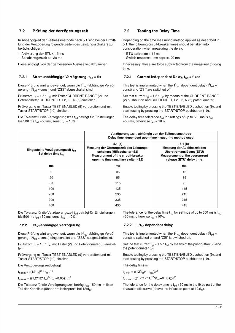
Verzögerungszeit, abhängig von der ZeitmessmethodeDelay time, dependent upon time measuring method used
Eingestellte Verzögerungszeit tsdSet delay time tsd
5.1 (a)Messung der Öffnungszeit des Leistungs-
schalters (Hilfsschalter -S2)Measurement of the circuit-breakeropening time (auxiliary switch -S2)
5.1 (b)Messung der Auslösezeit des
Überstromauslösers (ETU)Measurement of the overcurrent
release (ETU) delay time
ms ms ms
0 35 15
20 55 35
80 115 95
100 135 115
200 235 215
300 335 315
400 435 415
7.2 Testing the Delay Time
Depending on the time measuring method applied as described in5.1, the following circuit-breaker times should be taken intoconsideration when measuring the delay:
- ETU activation ≤ 15 ms
- Switch response time approx. 20 msIf necessary, these are to be subtracted from the measured trippingtime.
7.2.1 Current-independent Delay, tsd = fixed
This test is implemented when the I2tsd dependent delay (I2tsd =
const) and “ZSI” are switched off.
Set test current Ip = 1.5 * Isd by means of the CURRENT RANGE(2) pushbutton and CURRENT L1, L2, L3, N (5) potentiometer.
Enable testing by pressing the TEST ENABLED pushbutton (9), andstart testing by pressing the START/STOP pushbutton (10).
The delay time tolerance tsd for settings of up to 500 ms is tsd +50 ms, otherwise tsd + 10%.
The tolerance for the delay time tsd for settings of up to 500 ms is tsd +50 ms, otherwise tsd +10%.
7.2.2 I²tsd dependent delay
This test is implemented when the I2tsd dependent delay (I2tsd =const) is switched on and "ZSI" is switched off.
Set the test current Ip = 1.5 * Isd by means of the pushbutton (2) andthe potentiometer (5).
Enable testing by pressing the TEST ENABLED pushbutton (9), andstart testing by pressing the START/STOP pushbutton (10).
The delay time is
ta min = ((12*In)2 * tsd)/ I2
ta max = ((1.2*12* In)2*(tsd+0.05s))/ I2
The tolerance for the delay time is tsd +50 ms in the fixed part of the
characteristic curve (above the inflection point at 12xIn).
5/11/2018 BA_3WL9111-0AT44-0AA0_Stand0511 - slidepdf.com
http://slidepdf.com/reader/full/ba3wl9111-0at44-0aa0stand0511 17/27
7 – 3
7.2.3 Zeitverkürzte Selektivitätssteuerung "ZSS"
Diese Prüfung wird angewendet, wenn "ZSS" eingeschaltet ist.Dazu ist der Anschluss eines ZSS-Cubicle Bus Moduls erforderlich.Die I
2t-Verzögerung muss ausgeschaltet sein. Die Verzögerungs-zeit tsd muß auf 80 ms oder höher eingestellt sein.
Einstellung des Prüfstromes wie unter 7.2.1.
7.2.3.1 Auslösung ohne Sperrsignal (am ZSS-Modul)
Prüfung mit Taster TEST ENABLED (9) vorbereiten und mit TasterSTART/STOP (10) einleiten.
Die Verzögerungszeit muss 50 bis 100 ms betragen.
7.2.3.2 Auslösung mit Sperrsignal (am ZSS-Modul)
Am ZSS-Modul die Klemmen -X1.3 und -X1.4 zur Simulation desSperrsignals des nachfolgenden Schalters kurzschließen.
Prüfung mit Taster TEST ENABLED (9) vorbereiten und mit TasterSTART/STOP (10) einleiten.
Die Verzögerungszeit muss gleich der am Auslöser eingestelltenZeit plus Toleranz betragen. Die Toleranz für die Verzögerungszeittsd beträgt für Einstellungen bis 500 ms tsd +50 ms, sonst tsd +10%.
7.2.3 Zone Selective Interlocking “ZSI”
This test is implemented when “ZSI” is switched on. A ZSI CubicleBus module must be connected to carry out this test. The I
2t delaymust be switched off. The tsd delay time must be set to 80 ms orhigher.
Set the test current as described in 7.2.1.
7.2.3.1 Tripping without a Blocking Signal (on ZSI Module)
Enable testing by pressing the TEST ENABLED pushbutton (9), andstart testing by pressing the START/STOP pushbutton (10).
The delay time must be between 50 and 100 ms.
7.2.3.2 Tripping with a Blocking Signal (on ZSI Module)
To simulate the blocking signal of the downstream circuit breaker,short circuit the terminals -X1.3 and -X1.4 on the ZSI module.
Enable testing by pressing the TEST ENABLED pushbutton (9), andstart testing by pressing the START/STOP pushbutton (10).
The delay time must be the same as the time set on the releaseplus tolerance. The tolerance for the delay time tsd for settings of upto 500 ms is tsd +50 ms, otherwise tsd +10%.
5/11/2018 BA_3WL9111-0AT44-0AA0_Stand0511 - slidepdf.com
http://slidepdf.com/reader/full/ba3wl9111-0at44-0aa0stand0511 18/27
8 – 1
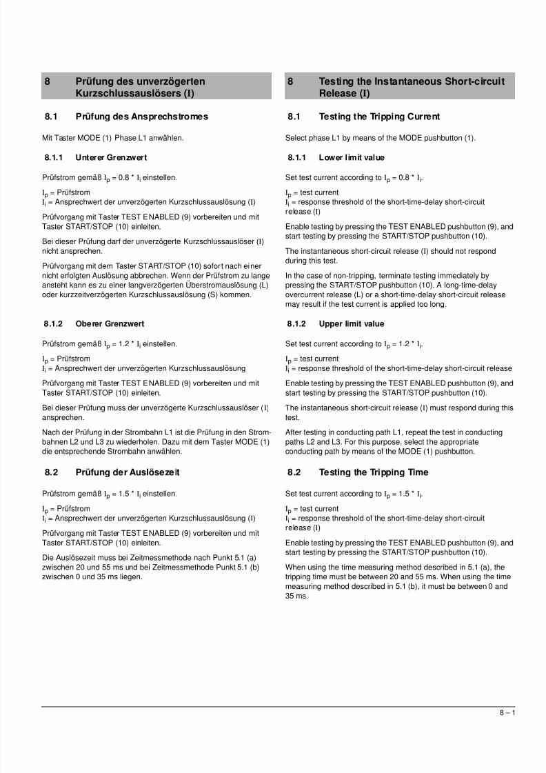
8 Testing the Instantaneous Short-circuitRelease (I)
8.1 Testing the Tripping Current
Select phase L1 by means of the MODE pushbutton (1).
8.1.1 Lower limit value
Set test current according to Ip = 0.8 * Ii.
Ip = test currentIi = response threshold of the short-time-delay short-circuitrelease (I)
Enable testing by pressing the TEST ENABLED pushbutton (9), andstart testing by pressing the START/STOP pushbutton (10).
The instantaneous short-circuit release (I) should not respondduring this test.
In the case of non-tripping, terminate testing immediately bypressing the START/STOP pushbutton (10). A long-time-delayovercurrent release (L) or a short-time-delay short-circuit releasemay result if the test current is applied too long.
8.1.2 Upper limit value
Set test current according to Ip = 1.2 * Ii.
Ip = test currentIi = response threshold of the short-time-delay short-circuit release
Enable testing by pressing the TEST ENABLED pushbutton (9), andstart testing by pressing the START/STOP pushbutton (10).
The instantaneous short-circuit release (I) must respond during thistest.
After testing in conducting path L1, repeat the test in conductingpaths L2 and L3. For this purpose, select the appropriateconducting path by means of the MODE (1) pushbutton.
8.2 Testing the Tripping Time
Set test current according to Ip = 1.5 * Ii.
Ip = test currentIi = response threshold of the short-time-delay short-circuitrelease (I)
Enable testing by pressing the TEST ENABLED pushbutton (9), andstart testing by pressing the START/STOP pushbutton (10).
When using the time measuring method described in 5.1 (a), thetripping time must be between 20 and 55 ms. When using the timemeasuring method described in 5.1 (b), it must be between 0 and35 ms.
8 Prüfung des unverzögertenKurzschlussauslösers (I)
8.1 Prüfung des Ansprechstromes
Mit Taster MODE (1) Phase L1 anwählen.
8.1.1 Unterer Grenzwert
Prüfstrom gemäß Ip = 0.8 * Ii einstellen.
Ip = PrüfstromIi = Ansprechwert der unverzögerten Kurzschlussauslösung (I)
Prüfvorgang mit Taster TEST ENABLED (9) vorbereiten und mitTaster START/STOP (10) einleiten.
Bei dieser Prüfung darf der unverzögerte Kurzschlussauslöser (I)nicht ansprechen.
Prüfvorgang mit dem Taster START/STOP (10) sofort nach einernicht erfolgten Auslösung abbrechen. Wenn der Prüfstrom zu langeansteht kann es zu einer langverzögerten Überstromauslösung (L)oder kurzzeitverzögerten Kurzschlussauslösung (S) kommen.
8.1.2 Oberer Grenzwert
Prüfstrom gemäß Ip = 1.2 * Ii einstellen.
Ip = PrüfstromIi = Ansprechwert der unverzögerten Kurzschlussauslösung
Prüfvorgang mit Taster TEST ENABLED (9) vorbereiten und mitTaster START/STOP (10) einleiten.
Bei dieser Prüfung muss der unverzögerte Kurzschlussauslöser (I)ansprechen.
Nach der Prüfung in der Strombahn L1 ist die Prüfung in den Strom-bahnen L2 und L3 zu wiederholen. Dazu mit dem Taster MODE (1)die entsprechende Strombahn anwählen.
8.2 Prüfung der Auslösezeit
Prüfstrom gemäß Ip = 1.5 * Ii einstellen.
Ip = PrüfstromIi = Ansprechwert der unverzögerten Kurzschlussauslösung (I)
Prüfvorgang mit Taster TEST ENABLED (9) vorbereiten und mitTaster START/STOP (10) einleiten.
Die Auslösezeit muss bei Zeitmessmethode nach Punkt 5.1 (a)zwischen 20 und 55 ms und bei Zeitmessmethode Punkt 5.1 (b)zwischen 0 und 35 ms liegen.
5/11/2018 BA_3WL9111-0AT44-0AA0_Stand0511 - slidepdf.com
http://slidepdf.com/reader/full/ba3wl9111-0at44-0aa0stand0511 19/27
9 – 1
9 Prüfung des Erdschlussauslösers (G)
9.1 Prüfung des Ansprechstromes bei derMessmethode „Vektorielle Summenbildung“
Mit Taster MODE (1) Phase L1 anwählen.
9.1.1 Unterer Grenzwert
Prüfstrom gemäß Ip = 0.8 * Ig einstellen.
Ip = PrüfstromI
g = Ansprechwert des kurzzeitverzögerten Erdschlussauslösers (g)Prüfvorgang mit Taster TEST ENABLED (9) vorbereiten und mitTaster START/STOP (10) einleiten.
Bei dieser Prüfung darf der kurzzeitverzögerte Erdschlussauslöser(G) nicht ansprechen.
Prüfvorgang mit dem Taster START/STOP (10) abbrechen.
9.1.2 Oberer Grenzwert
Prüfstrom gemäß Ip = 1.2 * Ig einstellen.
Ip = PrüfstromIg = Ansprechwert des kurzzeitverzögerten Erdschlussauslösers (g)
Prüfvorgang mit Taster TEST ENABLED (9) vorbereiten und mitTaster START/STOP (10) einleiten.
Bei dieser Prüfung muss der kurzzeitverzögerte Erdschlussauslöser(G) ansprechen.
9.1.3 Prüfung der Verzögerungszeit
In Abhängigkeit der Zeitmessmethode nach 5.1 sind bei der Ermitt-lung der Verzögerung folgende Zeiten des Leistungsschalters zuberücksichtigen:
- Aktivierung der ETU ≤ 15 ms- Schaltereigenzeit ca. 20 ms
Diese sind ggf. von der gemessenen Auslösezeit abzuziehen.
9.1.3.1 Stromunabhängige Verzögerung, tg = fix
Diese Prüfung wird angewendet, wenn die I2tg-abhängige Verzöge-
rung (I2tg = const) und "ZSS" abgeschaltet sind.
Prüfstrom Ip = 1.5 * Ig mit Taster (2) und Potentiometer (5) einstel-len.
Ip = Prüfstrom
Ig = Ansprechwert des kurzzeitverzögerten Erdschlussauslösers (g)
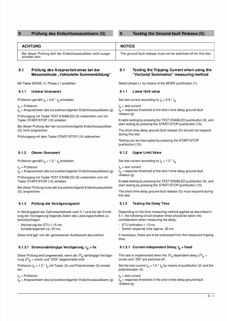
ACHTUNG NOTICE
Bei dieser Prüfung darf der Erdschlussauslöser nicht ausge-schaltet sein.
The ground-fault release must not be switched off for this test.
9 Testing the Ground-fault Release (G)
9.1 Testing the Tripping Current when using the“Vectorial Summation” measuring method
Select phase L1 by means of the MODE pushbutton (1).
9.1.1 Lower limit value
Set test current according to Ip = 0.8 * Ig.
Ip = test currentI
g = response threshold of the short-time-delay ground-faultrelease (g)
Enable testing by pressing the TEST ENABLED pushbutton (9), andstart testing by pressing the START/STOP pushbutton (10).
The short-time-delay ground-fault release (G) should not respondduring this test.
Testing can be interrupted by pressing the START/STOPpushbutton (10).
9.1.2 Upper Limit Value
Set test current according to Ip = 1.2 * Ig.
Ip = test currentIg = response threshold of the short-time-delay ground-faultrelease (g)
Enable testing by pressing the TEST ENABLED pushbutton (9), andstart testing by pressing the START/STOP pushbutton (10).
The short-time-delay ground-fault release (G) must respond duringthis test.
9.1.3 Testing the Delay Time
Depending on the time measuring method applied as described in5.1, the following circuit-breaker times should be taken intoconsideration when measuring the delay:
- ETU activation ≤ 15 ms- Switch response time approx. 20 ms
If necessary, these are to be subtracted from the measured trippingtime.
9.1.3.1 Current-independent Delay, tg = fixed
This test is implemented when the I2tg dependent delay (I2tg =
const) and “ZSI” are switched off.
Set the test current Ip = 1.5 * Ig by means of pushbutton (2) and thepotentiometer (5).
Ip = test current
Ig = response threshold of the short-time-delay ground-faultrelease (g)
5/11/2018 BA_3WL9111-0AT44-0AA0_Stand0511 - slidepdf.com
http://slidepdf.com/reader/full/ba3wl9111-0at44-0aa0stand0511 20/27
9 – 2
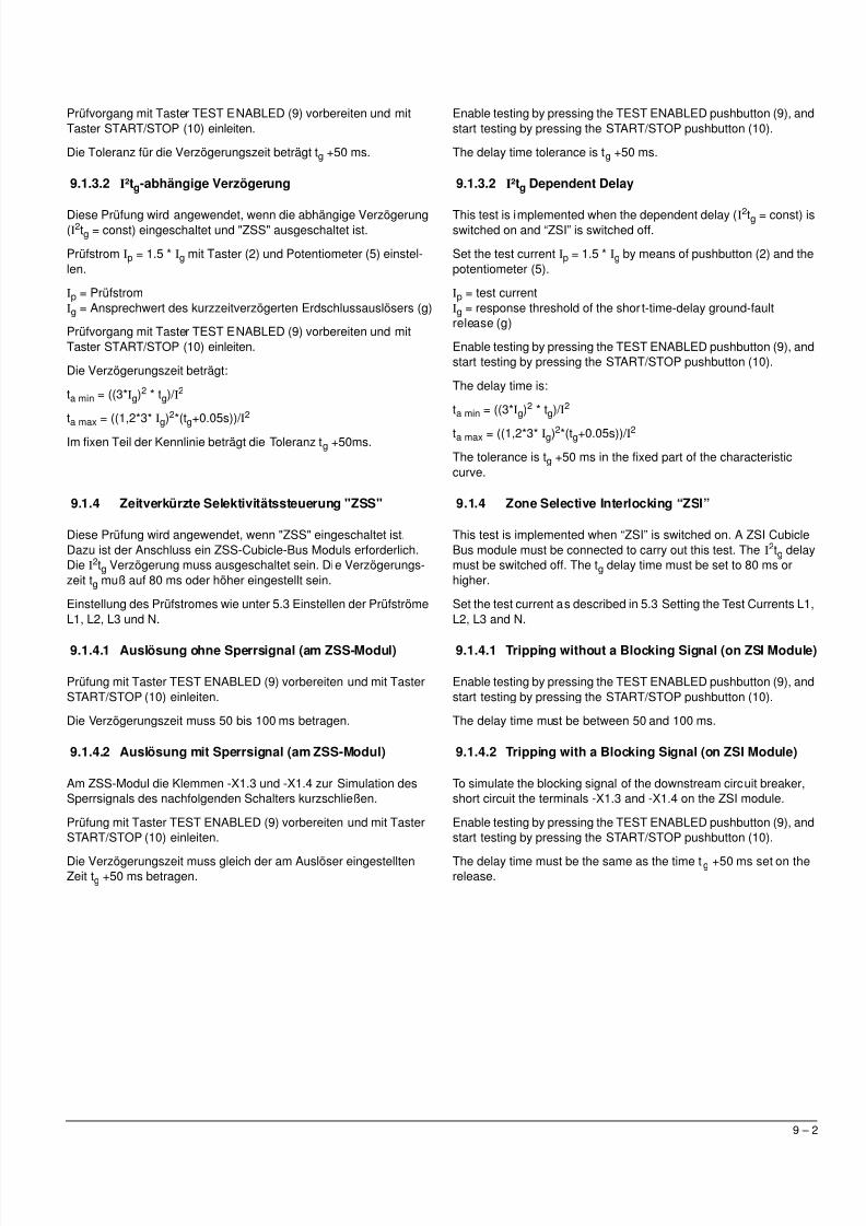
Prüfvorgang mit Taster TEST ENABLED (9) vorbereiten und mitTaster START/STOP (10) einleiten.
Die Toleranz für die Verzögerungszeit beträgt tg +50 ms.
9.1.3.2 I²tg-abhängige Verzögerung
Diese Prüfung wird angewendet, wenn die abhängige Verzögerung(I2tg = const) eingeschaltet und "ZSS" ausgeschaltet ist.
Prüfstrom Ip = 1.5 * Ig mit Taster (2) und Potentiometer (5) einstel-len.
Ip = PrüfstromIg = Ansprechwert des kurzzeitverzögerten Erdschlussauslösers (g)
Prüfvorgang mit Taster TEST ENABLED (9) vorbereiten und mitTaster START/STOP (10) einleiten.
Die Verzögerungszeit beträgt:
ta min = ((3*Ig)2 * tg)/ I2
ta max
= ((1,2*3* I
g)2*(t
g+0.05s))/ I2
Im fixen Teil der Kennlinie beträgt die Toleranz tg +50ms.
9.1.4 Zeitverkürzte Selektivitätssteuerung "ZSS"
Diese Prüfung wird angewendet, wenn "ZSS" eingeschaltet ist.Dazu ist der Anschluss ein ZSS-Cubicle-Bus Moduls erforderlich.Die I
2tg Verzögerung muss ausgeschaltet sein. Die Verzögerungs-zeit tg muß auf 80 ms oder höher eingestellt sein.
Einstellung des Prüfstromes wie unter 5.3 Einstellen der PrüfströmeL1, L2, L3 und N.
9.1.4.1 Auslösung ohne Sperrsignal (am ZSS-Modul)
Prüfung mit Taster TEST ENABLED (9) vorbereiten und mit TasterSTART/STOP (10) einleiten.
Die Verzögerungszeit muss 50 bis 100 ms betragen.
9.1.4.2 Auslösung mit Sperrsignal (am ZSS-Modul)
Am ZSS-Modul die Klemmen -X1.3 und -X1.4 zur Simulation desSperrsignals des nachfolgenden Schalters kurzschließen.
Prüfung mit Taster TEST ENABLED (9) vorbereiten und mit TasterSTART/STOP (10) einleiten.
Die Verzögerungszeit muss gleich der am Auslöser eingestelltenZeit tg +50 ms betragen.
Enable testing by pressing the TEST ENABLED pushbutton (9), andstart testing by pressing the START/STOP pushbutton (10).
The delay time tolerance is tg +50 ms.
9.1.3.2 I²tg Dependent Delay
This test is implemented when the dependent delay (I2tg = const) isswitched on and “ZSI” is switched off.
Set the test current Ip = 1.5 * Ig by means of pushbutton (2) and thepotentiometer (5).
Ip = test currentIg = response threshold of the short-time-delay ground-faultrelease (g)
Enable testing by pressing the TEST ENABLED pushbutton (9), andstart testing by pressing the START/STOP pushbutton (10).
The delay time is:
ta min = ((3*Ig)2 * tg)/ I2
ta max = ((1,2*3* Ig)2*(tg+0.05s))/ I2
The tolerance is tg +50 ms in the fixed part of the characteristiccurve.
9.1.4 Zone Selective Interlocking “ZSI”
This test is implemented when “ZSI” is switched on. A ZSI CubicleBus module must be connected to carry out this test. The I
2tg delaymust be switched off. The tg delay time must be set to 80 ms orhigher.
Set the test current as described in 5.3 Setting the Test Currents L1,L2, L3 and N.
9.1.4.1 Tripping without a Blocking Signal (on ZSI Module)
Enable testing by pressing the TEST ENABLED pushbutton (9), andstart testing by pressing the START/STOP pushbutton (10).
The delay time must be between 50 and 100 ms.
9.1.4.2 Tripping with a Blocking Signal (on ZSI Module)
To simulate the blocking signal of the downstream circuit breaker,short circuit the terminals -X1.3 and -X1.4 on the ZSI module.
Enable testing by pressing the TEST ENABLED pushbutton (9), andstart testing by pressing the START/STOP pushbutton (10).
The delay time must be the same as the time tg +50 ms set on therelease.
5/11/2018 BA_3WL9111-0AT44-0AA0_Stand0511 - slidepdf.com
http://slidepdf.com/reader/full/ba3wl9111-0at44-0aa0stand0511 21/27
9 – 3
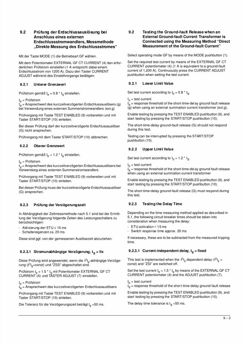
9.2 Prüfung der Erdschlussauslösung beiAnschluss eines externenErdschlussstromwandlers, Messmethode„Direkte Messung des Erdschlussstromes“
Mit der Taste MODE (1) die Betriebsart GF wählen.
Mit dem Potentiometer EXTERNAL GF CT CURRENT (4) den erfor-derlichen Prüfstrom einstellen (1 A entspricht dabei einemErdschlussstrom von 1200 A). Dazu den Taster CURRENTADJUST während des Einstellvorgangs betätigen.
9.2.1 Unterer Grenzwert
Prüfstrom gemäß Ip = 0.8 * Ig einstellen.
Ip = PrüfstromIg = Ansprechwert des kurzzeitverzögerten Erdschlussauslösers (g)bei Verwendung eines externen Summenstromwandlers (ext.g)
Prüfvorgang mit Taster TEST ENABLED (9) vorbereiten und mit
Taster START/STOP (10) einleiten.Bei dieser Prüfung darf der kurzzeitverzögerte Erdschlussauslöser(G) nicht ansprechen.
Prüfvorgang mit dem Taster START/STOP (10) abbrechen.
9.2.2 Oberer Grenzwert
Prüfstrom gemäß Ip = 1.2 * Ig einstellen.
Ip = PrüfstromIg = Ansprechwert des kurzzeitverzögerten Erdschlussauslösers beiVerwendung eines externen Summenstromwandlers
Prüfvorgang mit Taster TEST ENABLED (9) vorbereiten und mit
Taster START/STOP (10) einleiten.
Bei dieser Prüfung muss der kurzzeitverzögerte Erdschlussauslöser(G) ansprechen.
9.2.3 Prüfung der Verzögerungszeit
In Abhängigkeit der Zeitmessmethode nach 5.1 sind bei der Ermitt-lung der Verzögerung folgende Zeiten des Leistungsschalters zuberücksichtigen:
- Aktivierung der ETU ≤ 15 ms- Schaltereigenzeit ca. 20 ms
Diese sind ggf. von der gemessenen Auslösezeit abzuziehen.
9.2.3.1 Stromunabhängige Verzögerung, tg = fix
Diese Prüfung wird angewendet, wenn die I2tg-abhängige Verzöge-
rung (I2tg=const) und "ZSS" abgeschaltet sind.
Prüfstrom Ip = 1.5 * Ig mit Potentiometer EXTERNAL GF CTCURRENT (4) und TASTER ADJUST (7) einstellen.
Ip = PrüfstromIg = Ansprechwert des kurzzeitverzögerten Erdschlussauslösers
Prüfvorgang mit Taster TEST ENABLED (9) vorbereiten und mitTaster START/STOP (10) einleiten.
Die Toleranz für die Verzögerungszeit beträgt tg +50 ms.
9.2 Testing the Ground-fault Release when anExternal Ground-fault Current Transformer isConnected using the Measuring Method “DirectMeasurement of the Ground-fault Current”
Select operating mode GF by means of the MODE pushbutton (1).
Set the required test current by means of the EXTERNAL GF CTCURRENT potentiometer (4) (1 A is equivalent to a ground-faultcurrent of 1,200 A). Continuously press the CURRENT ADJUSTpushbutton when setting the test current.
9.2.1 Lower Limit Value
Set test current according to Ip = 0.8 * Ig.
Ip = test currentIg = response threshold of the short-time-delay ground-fault release(g) when using an external summation current transformer (ext.g).
Enable testing by pressing the TEST ENABLED pushbutton (9), and
start testing by pressing the START/STOP pushbutton (10).The short-time-delay ground-fault release (G) should not respondduring this test.
Testing can be interrupted by pressing the START/STOPpushbutton (10).
9.2.2 Upper Limit Value
Set test current according to Ip = 1.2 * Ig.
Ip = test currentIg = response threshold of the short-time-delay ground-fault releasewhen using an external summation current transformer
Enable testing by pressing the TEST ENABLED pushbutton (9), andstart testing by pressing the START/STOP pushbutton (10).
The short-time-delay ground-fault release (G) must respond duringthis test.
9.2.3 Testing the Delay Time
Depending on the time measuring method applied as described in5.1, the following circuit-breaker times should be taken intoconsideration when measuring the delay:
- ETU activation ≤ 15 ms- Switch response time approx. 20 ms
If necessary, these are to be subtracted from the measured trippingtime.
9.2.3.1 Current-independent delay, tg = fixed
This test is implemented when the I2tg dependent delay (I2tg =
const) and “ZSI” are switched off.
Set the test current Ip = 1.5 * Ig by means of the EXTERNAL GF CTCURRENT potentiometer (4) and the ADJUST pushbutton (7).
Ip = test currentIg = response threshold of the short-time-delay ground-fault release
Enable testing by pressing the TEST ENABLED pushbutton (9), andstart testing by pressing the START/STOP pushbutton (10).
The delay time tolerance is tg +50 ms.
5/11/2018 BA_3WL9111-0AT44-0AA0_Stand0511 - slidepdf.com
http://slidepdf.com/reader/full/ba3wl9111-0at44-0aa0stand0511 22/27
9 – 4
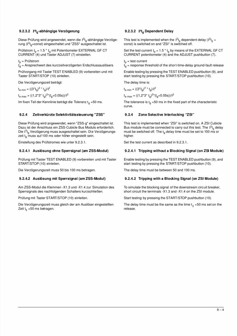
9.2.3.2 I²tg-abhängige Verzögerung
Diese Prüfung wird angewendet, wenn die I2tg-abhängige Verzöge-
rung (I2tg=const) eingeschaltet und "ZSS" ausgeschaltet ist.
Prüfstrom Ip = 1.5 * Ig mit Potentiometer EXTERNAL GF CTCURRENT (4) und Taster ADJUST (7) einstellen.
Ip = PrüfstromIg = Ansprechwert des kurzzeitverzögerten Erdschlussauslösers
Prüfvorgang mit Taster TEST ENABLED (9) vorbereiten und mitTaster START/STOP (10) einleiten.
Die Verzögerungszeit beträgt:
ta min = ((3*Ig)2 * tg)/ I2
ta max = ((1,2*3* Ig)2*(tg+0.05s))/ I2
Im fixen Teil der Kennlinie beträgt die Toleranz tg +50 ms.
9.2.4 Zeitverkürzte Selektivitätssteuerung "ZSS"
Diese Prüfung wird angewendet, wenn "ZSS-g" eingeschaltet ist.Dazu ist der Anschluss ein ZSS-Cubicle Bus Moduls erforderlich.Die I
2tg Verzögerung muss ausgeschaltet sein. Die Verzögerungs-zeit tg muss auf 100 ms oder höher eingestellt sein.
Einstellung des Prüfstromes wie unter 9.2.3.1.
9.2.4.1 Auslösung ohne Sperrsignal (am ZSS-Modul)
Prüfung mit Taster TEST ENABLED (9) vorbereiten und mit TasterSTART/STOP (10) einleiten.
Die Verzögerungszeit muss 50 bis 100 ms betragen.
9.2.4.2 Auslösung mit Sperrsignal (am ZSS-Modul)
Am ZSS-Modul die Klemmen -X1.3 und -X1.4 zur Simulation desSperrsignals des nachfolgenden Schalters kurzschließen.
Prüfung mit Taster START/STOP (10) einleiten.
Die Verzögerungszeit muss gleich der am Auslöser eingestelltenZeit tg +50 ms betragen.
9.2.3.2 I²tg Dependent Delay
This test is implemented when the I2tg dependent delay (I2tg =
const) is switched on and “ZSI” is switched off.
Set the test current Ip = 1.5 * Ig by means of the EXTERNAL GF CTCURRENT potentiometer (4) and the ADJUST pushbutton (7).
Ip = test currentIg = response threshold of the short-time-delay ground-fault release
Enable testing by pressing the TEST ENABLED pushbutton (9), andstart testing by pressing the START/STOP pushbutton (10).
The delay time is:
ta min = ((3*Ig)2 * tg)/ I2
ta max = ((1,2*3* Ig)2*(tg+0.05s))/ I2
The tolerance is tg +50 ms in the fixed part of the characteristiccurve.
9.2.4 Zone Selective Interlocking “ZSI”
This test is implemented when “ZSI” is switched on. A ZSI CubicleBus module must be connected to carry out this test. The I
2tg delaymust be switched off. The tg delay time must be set to 100 ms orhigher.
Set the test current as described in 9.2.3.1.
9.2.4.1 Tripping without a Blocking Signal (on ZSI Module)
Enable testing by pressing the TEST ENABLED pushbutton (9), andstart testing by pressing the START/STOP pushbutton (10).
The delay time must be between 50 and 100 ms.
9.2.4.2 Tripping with a Blocking Signal (on ZSI Module)
To simulate the blocking signal of the downstream circuit breaker,short circuit the terminals -X1.3 and -X1.4 on the ZSI module.
Start testing by pressing the START/STOP pushbutton (10).
The delay time must be the same as the time tg +50 ms set on therelease.

5/11/2018 BA_3WL9111-0AT44-0AA0_Stand0511 - slidepdf.com
http://slidepdf.com/reader/full/ba3wl9111-0at44-0aa0stand0511 23/27
10 – 1
10 Testing the Signaling Functions
For each of the previously described tr ipping function tests, the tripcause can be traced after tripping by means of the QUERYpushbutton on the overcurrent release. The LED allotted to the
respective tripping function L, N, S, I and G will then light upaccordingly.
10 Prüfung der Meldefunktionen
Bei jeder der vorstehend beschriebenen Prüfungen der Auslöse-funktionen kann nach einer Auslösung der Auslösegrund mit derTaste QUERY des Überstromauslösers abgefragt werden. Die der
jeweiligen Auslösefunktion L, N, S, I oder G zugeordnete LED mussdann aufleuchten.
5/11/2018 BA_3WL9111-0AT44-0AA0_Stand0511 - slidepdf.com
http://slidepdf.com/reader/full/ba3wl9111-0at44-0aa0stand0511 24/27
11 – 1
11 Testing the Tripping Solenoid
The overcurrent release must be mounted in the circuit breaker tocarry out this test.
The circuit breaker must be switched on.
In order to test the tripping solenoid, start any one of the testsdescribed above and wait for the tripping command of theovercurrent release. The circuit breaker must switch off in theprocess.
If the circuit breaker does not switch off, the following causes mayapply:
- The connecting cable (X22) for the tripping solenoid has notbeen plugged in correctly
- The tripping solenoid is defective- Faulty coordination between the tripping solenoid and the
switch latching- Overcurrent release is defective
11 Prüfung des Auslösemagneten
Für diese Prüfung muss der Überstromauslöser in den Leistungs-schalter eingesetzt sein.
Der Leistungsschalter muss eingeschaltet sein.
Zur Prüfung des Auslösemagneten eine beliebige der beschriebe-nen Prüfungen einleiten und das Auslösekommando des Über-stromauslösers abwarten. Dabei muss der Leistungsschalterabschalten.
Wird der Schalter nicht ausgeschaltet, sind folgende Ursachenmöglich:
- Anschlussleitung des Auslösemagneten (X22) nicht richtigeingesteckt
- Defekter Auslösemagnet- Fehler im Zusammenwirken zwischen Auslösemagnet und
Schalterverklinkung- Fehler im Überstromauslöser
5/11/2018 BA_3WL9111-0AT44-0AA0_Stand0511 - slidepdf.com
http://slidepdf.com/reader/full/ba3wl9111-0at44-0aa0stand0511 25/27
12 – 1
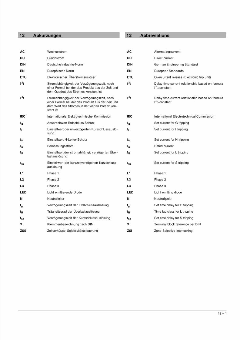
12 Abkürzungen
AC Wechselstrom
DC GleichstromDIN Deutsche Industrie-Norm
EN Europäische Norm
ETU Elektronischer Überstromauslöser
I2t Stromabhängigkeit der Verzögerungszeit, nach
einer Formel bei der das Produkt aus der Zeit unddem Quadrat des Stromes konstant ist
I4t Stromabhängigkeit der Verzögerungszeit, nach
einer Formel bei der das Produkt aus der Zeit unddem Wert des Stromes in der vierten Potenz kon-stant ist
IEC Internationale Elektrotechnische Kommission
Ig Ansprechwert Erdschluss-Schutz
Ii Einstellwert der unverzögerten Kurzschlussauslö-sung
IN Einstellwert N-Leiter-Schutz
In Bemessungsstrom
IR Einstellwert der stromabhängig verzögerten Über-lastauslösung
Isd Einstellwert der kurzzeitverzögerten Kurzschluss-auslösung
L1 Phase 1
L2 Phase 2
L3 Phase 3
LED Licht emittierende Diode
N Neutralleiter
tg Verzögerungszeit der Erdschlussauslösung
tR Trägheitsgrad der Überlastauslösung
tsd Verzögerungszeit der Kurzschlussauslösung
X Klemmenbezeichnung nach DIN
ZSS Zeitverkürzte Selektivitätssteuerung
12 Abbreviations
AC Alternating current
DC Direct currentDIN German Engineering Standard
EN European Standards
ETU Overcurrent release (Electronic trip unit)
I2t Delay time-current relationship based on formula
I2t=constant
I4t Delay time-current relationship based on formula
I4t=constant
IEC International Electrotechnical Commission
Ig Set current for G tripping
Ii Set current for I tripping
IN Set current for N tripping
In Rated current
IR Set current for L tripping
Isd Set current for S tripping
L1 Phase 1
L2 Phase 2
L3 Phase 3
LED Light emitting diode
N Neutral pole
tg Set time delay for G tripping
tR Time lag class for L tripping
tsd Set time delay for S tripping
X Terminal block reference per DIN
ZSI Zone Selective Interlocking
5/11/2018 BA_3WL9111-0AT44-0AA0_Stand0511 - slidepdf.com
http://slidepdf.com/reader/full/ba3wl9111-0at44-0aa0stand0511 26/27
13 – 1
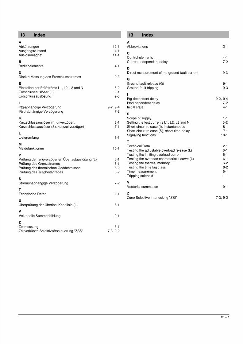
13 Index
AAbkürzungen 12-1Ausgangszustand 4-1Auslösemagnet 11-1
BBedienelemente 4-1
DDirekte Messung des Erdschlussstromes 9-3
EEinstellen der Prüfströme L1, L2, L3 und N 5-2Erdschlussauslöser (G) 9-1Erdschlussauslösung 9-3
II²tg-abhängige Verzögerung 9-2, 9-4I²tsd-abhängige Verzögerung 7-2
KKurzschlussauslöser (I), unverzögert 8-1Kurzschlussauslöser (S), kurzzeitverzögert 7-1
LLieferumfang 1-1
MMeldefunktionen 10-1
PPrüfung der langverzögerten Überlastauslösung (L) 6-1Prüfung des Grenzstromes 6-1Prüfung des thermischen Gedächtnisses 6-2Prüfung des Trägheitsgrades 6-2
SStromunabhängige Verzögerung 7-2
TTechnische Daten 2-1
UÜberprüfung der Überlast Kennlinie (L) 6-1
VVektorielle Summenbildung 9-1
ZZeitmessung 5-1Zeitverkürzte Selektivitätssteuerung "ZSS" 7-3, 9-2
13 Index
AAbbreviations 12-1
CControl elements 4-1Current-independent delay 7-2
DDirect measurement of the ground-fault current 9-3
GGround fault release (G) 9-1Ground-fault tripping 9-3
II²tg dependent delay 9-2, 9-4I²tsd dependent delay 7-2Initial state 4-1
S
Scope of supply 1-1Setting the test currents L1, L2, L3 and N 5-2Short-circuit release (I), instantaneous 8-1Short-circuit release (S), short-time-delay 7-1Signaling functions 10-1
TTechnical Data 2-1Testing the adjustable overload release (L) 6-1Testing the limiting overload current 6-1Testing the overload characteristic curve (L) 6-1Testing the thermal memory 6-2Testing the time lag class 6-2Time measurement 5-1Tripping solenoid 11-1
VVectorial summation 9-1
ZZone Selective Interlocking "ZSI" 7-3, 9-2

5/11/2018 BA_3WL9111-0AT44-0AA0_Stand0511 - slidepdf.com
http://slidepdf.com/reader/full/ba3wl9111-0at44-0aa0stand0511 27/27
Technische Änderungen vorbehaltenSubject to change without prior notice © Siemens AG 11.2005
Bestell-Nr. / Order No.: 3ZX1812-0WL93-0AN0
Printed in the Federal Republic of Germany
Technical Assistance: Tel: +49 911 895-5900 (8°° - 17°° MEZ/CET) Fax: +49 911 895-5907E-mail: [email protected] Internet: www.ad.siemens.de/support


