Embed Size (px)
Citation preview
J. Cent. South Univ. (2013) 20: 2072−2082DOI: 10.1007/s11771-013-1709-2
Design method of pile-slab structure roadbed ofballastless track on soil subgrade
ZHAN Yong-xiang(詹永祥)1, 2, YAO Hai-lin(姚海林)1, 2, JIANG Guan-lu(蒋关鲁)3
1. Institute of Rock and Soil Mechanics, Chinese Academy of Sciences, Wuhan 430071, China;2. State Key Laboratory of Geomechanics and Geotechnical Engineering (Institute of Rock and soil Mechanics,
Chinese Academy of Sciences), Wuhan 430071, China;3. School of Civil Engineering, Southwest Jiaotong University, Chengdu 610031, China
© Central South University Press and Springer-Verlag Berlin Heidelberg 2013
Abstract: Pile−slab structure roadbed is a new form of ballastless track for high speed railway. Due to lack of corresponding designcode, based on the analysis of its structure characteristics and application requirements, it is proposed to carry out load effectcombination according to ultimate limit state and serviceability limit state, and the most unfavorable combination of each state ischosen to carry through design calculation for pile-slab structure. Space model of pile−slab structure can be simplified as a planeframe model, by using the orthogonal test method, and the design parameter of pile-slab structure is optimized. Moreover, based onthe engineering background of Suining−Chongqing high-speed railway, the dynamic deformation characteristics of pile-slab structureroadbed are further researched by carrying on the indoor dynamic model test. The test results show that the settlement afterconstruction of subgrade satisfies the requirement of settlement control to build ballastless track on soil subgrade for high-speedrailway. Slab structure plays the role of arch shell as load is transmitted from slab to pile, and the vertical dynamic stress of subgradesoil is approximately of “K” form distribution with the depth. The distribution of pile stress is closely related to soil characteristics,which has an upset triangle shape where the large dynamic stress is at the top. Pile compared with soil shares most dynamic stress.Pile structure expands the depth of the dynamic response of subgrade and improves the stress of subgrade soil, and the speed of trainhas limited effect on dynamic response. These results can provide scientific basis for pile−slab structure roadbed used on soilsubgrade.
Key words: soil subgrade; ballastless track; pile-slab structure roadbed; load combination; dynamic model test
1 Introduction
For large scale of construction and long route ofhigh-speed railway with the complexity of the regionalgeological conditions in China, it is difficult for part ofsector to control the settlement after construction byusing conventional foundation treatment in engineeringdesign, and it needs to seek a new roadbed structure andnew construction method. Pile−slab structure roadbed isa new form of ballastless track for high-speed railway,which consists of the lower part of reinforced concretepile foundation, embankment noumenon and the upperpart of reinforced concrete bearing slab and joist. Thebearing slab is directly connected with the track structure,which is a long muti-span continuous reinforced concreteslab. For pile−slab structure roadbed, it depends on theinteraction of pile, slab and soil to meet the requirementsof the strength and deformation of ballastless track, asshown in Fig. 1 [1−3]. So, it is not only a new form of
ballastless track structure, but also a new type of groundtreatment method. Since the structure can effectivelycontrol the settlement of foundation and speed upconstruction schedule, it has been widely used in anumber of national trunk railways. For example, it hasbeen used in overseas such as Turku−Toijala railway inFinland, the connection line of submarine tunnel betweenBritish and France, the southern section of Dutch highspeed railway (HSL-s line), and Nuremberg−Iugolstadt
Fig. 1 Section plane of pile−slab embankment
Foundation item: Project(2013CB036405) supported by the National Basic Research Program of China; Project(KZZD-EW-05) supported by the KeyResearch Program of the Chinese Academy of Sciences
Received date: 2012−09−10; Accepted date: 2013−04−10Corresponding author: ZHAN Yong-xiang, PhD; Tel: +86−27−87198350; E-mail: [email protected]
J. Cent. South Univ. (2013) 20: 2072−2082 2073
new high-speed railway of German [4], and in Chinasuch as Suining−Chongqing high-speed railway andWuhan−Guangzhou high-speed railway [5].
Currently, although pile−slab structure has beenwidely used, the research documents are still relativelyrare. Since there is no code for the design and thedynamic design theory has not been established, thevalues of dynamic parameters are only obtained in theview of bridge structural design. In some respects,pile−slab structure is similar to plate girder bridge withpath of force transfer [6−10], but there are manydifferences between them as follows. First, it is no pierstructure and no bridge bearing for pile−slab structure, sothe connection mode between slab and pile is differentfrom that between beam and pier. Then, pile groupfoundation is used under each pier foundation for platebridge structure, while single pile foundation is used forpile−slab structure, and the span and pile type aredifferent between them. Finally, there is a certainclearance under plate girder for bridge structure, whilefor pile-slab structure, bearing slab is contacted withsubgrade soil, which is a joint action with soil for a longtime. Therefore, it is not reasonable for the dynamicdesign parameters to be obtained on the basis of bridgestructure. In order to meet the requirements of dynamicdesign of pile−slab structure on soil subgrade, based onSuining−Chongqing high-speed railway, the designmethod is researched in this work.
2 Design method of pile−slab structureroadbed
2.1 Design ideaFor the design of pile−slab structure roadbed, load
combinations [11−13] (the load classification includingpermanent load, variable load and accidental load)should first be carried out depending on permissiblevalue at different states (including ultimate limit stateand serviceability limit state), the most unfavorable oneshould be selected under different load combinations,then the strength, stability and deformation of thesubgrade are researched according to the mechanicalmodel of pile−slab structure, and finally the safety andcomfort of train operation are evaluated.
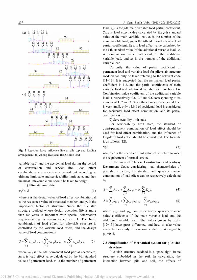
Design ideas are as follows. First, according to thegeological condition and the longitudinal layout of line,longitudinal pile spacing is set, the reinforced concretebearing slab is regarded as continuous one-way slab, andtrain live load is laid out at the most unfavorable positionaccording to live load representative figure by usinginfluence line method, as shown in Fig. 2 and Fig. 3.Then, the size of bearing slab is assumed, the internalforce and the deflection of which can be calculated undercombined load. The reinforcement of slab can be
Fig. 2 Influence line of displacement at middle span andloading arrangement: (a) Zhong-live load; (b) ZK live load
calculated according to the theory of beam−platestructure, which finally determines whether the warpingdeformation of the slab satisfies the requirements ofballastless track built on soil subgrade [13]. Thesubstructure of pile-slab structure is pile foundation, andthe pile section form, pile diameter and longitudinal pilespacing can be determined on the basis of pile bearingcapacity. Superstructure load transfers to pile top bysupport reaction, and lateral and longitudinal pileresistances are calculated by the theory of pilefoundation. Then, by adjusting the longitudinal pilespacing, a series of combination schemes of pile−slabstructure can be obtained, and the best one can be finallyselected according to the performance price ratio andpractical engineering requirement.
2.2 Load combinationThe train load can be simplified as Zhong-live load
and ZK live load, which is laid out at the mostunfavorable position according to longitudinal influenceline. Moreover, the load effect must be consideredincluding the permanent load, the variable load(including the main variable load and the additional
J. Cent. South Univ. (2013) 20: 2072−20822074
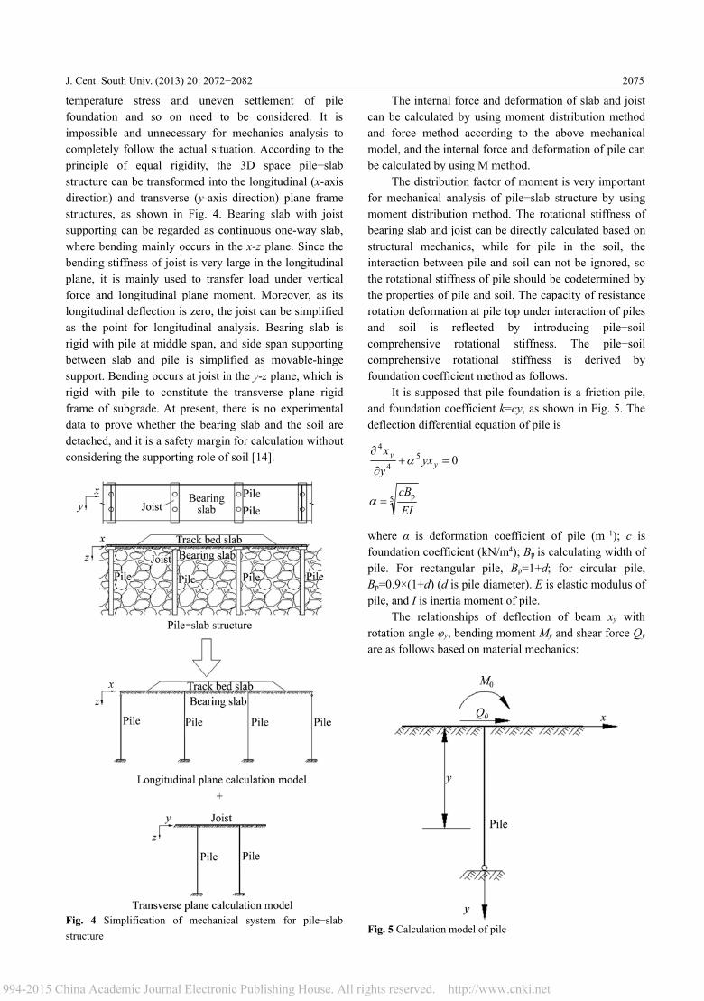
Fig. 3 Reaction force influence line at pile top and loadingarrangement: (a) Zhong-live load; (b) ZK live load
variable load) and the accidental load during the periodof construction and service life. Load effectcombinations are respectively carried out according toultimate limit state and serviceability limit state, and thenthe most unfavorable one should be taken to design.
1) Ultimate limit stateRS ≤0γ (1)
where S is the design value of load effect combination, Ris the resistance value of structural member, and γ0 is theimportance factor of structure. Since the pile−slabstructure roadbed whose design operation life is morethan 60 years is important with special deformationrequirement, γ0 is recommended as 1.1. The basiccombination of load effect for pile−slab structure iscontrolled by the variable load effect, and the designvalue of load combination is
∑ ∑ ∑= = =
++=m
i
n
j
n
llkljkjiki SSSS
1 1 1 Q, Q,c Q, Q, G, G,
1 2
γψγγ (2)
where γG, i is the i-th permanent load partial coefficient,SG, ik is load effect value calculated by the i-th standardvalue of permanent load, m is the number of permanent
load, γQ,j is the j-th main variable load partial coefficient,SQ, jk is load effect value calculated by the j-th standardvalue of the main variable load, n1 is the number of themain variable load, γQ,l is the l-th additional variable loadpartial coefficient, SQ, lk is load effect value calculated bythe l-th standard value of the additional variable load, ψc
is combination value coefficient of the additionalvariable load, and n2 is the number of the additionalvariable load.
Currently, the value of partial coefficient ofpermanent load and variable load for pile−slab structureroadbed can only be taken referring to the relevant code[11−13]. It is suggested that the permanent load partialcoefficient is 1.2, and the partial coefficients of mainvariable load and additional variable load are both 1.4.Combination value coefficient of the additional variableload is, respectively, 0.8, 0.7 and 0.6 corresponding to itsnumber of 1, 2 and 3. Since the chance of accidental loadis very small, only a kind of accidental load is consideredfor accidental load effect combination, and its partialcoefficient is 1.0.
2) Serviceability limit stateFor serviceability limit state, the standard or
quasi-permanent combination of load effect should beused for load effect combination, and the influence oflong-term load effect should be considered. The formulais as follows [12]:
S≤C (3)
where C is the specified limit value of structure to meetthe requirement of normal service.
In the view of Chinese Construction and RailwayDepartment Code, considering load characteristics ofpile−slab structure, the standard and quasi-permanentcombination of load effect can be respectively calculatedby
∑ ∑ ∑= = =
++=m
i
n
j
n
llkjkik SSSS
1 1 1 Q,c Q, G,
1 2
ψ (4)
∑ ∑ ∑= = =
++=m
i
n
j
n
llkljkjik SSSS
1 1 1 Q, q, Q, q, G,
1 2
ψψ (5)
where ψq,j and ψq,l are respectively quasi-permanentvalue coefficients of the main variable load and theadditional variable load. The values given by Refs.[12−13] have great difference, and how to take valueneeds further study. It is recommended to take ψq,j=0.6,ψq,l=0. 3.
2.3 Simplification of mechanical system for pile−slabstructurePile−slab structure roadbed is a space rigid frame
structure embedded in the soil. In calculation, theinteraction between pile and soil, the effects of
J. Cent. South Univ. (2013) 20: 2072−2082 2075
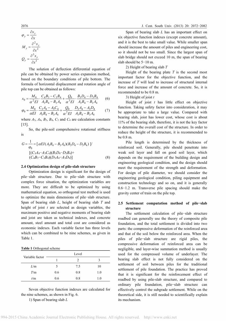
temperature stress and uneven settlement of pilefoundation and so on need to be considered. It isimpossible and unnecessary for mechanics analysis tocompletely follow the actual situation. According to theprinciple of equal rigidity, the 3D space pile−slabstructure can be transformed into the longitudinal (x-axisdirection) and transverse (y-axis direction) plane framestructures, as shown in Fig. 4. Bearing slab with joistsupporting can be regarded as continuous one-way slab,where bending mainly occurs in the x-z plane. Since thebending stiffness of joist is very large in the longitudinalplane, it is mainly used to transfer load under verticalforce and longitudinal plane moment. Moreover, as itslongitudinal deflection is zero, the joist can be simplifiedas the point for longitudinal analysis. Bearing slab isrigid with pile at middle span, and side span supportingbetween slab and pile is simplified as movable-hingesupport. Bending occurs at joist in the y-z plane, which isrigid with pile to constitute the transverse plane rigidframe of subgrade. At present, there is no experimentaldata to prove whether the bearing slab and the soil aredetached, and it is a safety margin for calculation withoutconsidering the supporting role of soil [14].
Fig. 4 Simplification of mechanical system for pile−slabstructure
The internal force and deformation of slab and joistcan be calculated by using moment distribution methodand force method according to the above mechanicalmodel, and the internal force and deformation of pile canbe calculated by using M method.
The distribution factor of moment is very importantfor mechanical analysis of pile−slab structure by usingmoment distribution method. The rotational stiffness ofbearing slab and joist can be directly calculated based onstructural mechanics, while for pile in the soil, theinteraction between pile and soil can not be ignored, sothe rotational stiffness of pile should be codetermined bythe properties of pile and soil. The capacity of resistancerotation deformation at pile top under interaction of pilesand soil is reflected by introducing pile−soilcomprehensive rotational stiffness. The pile−soilcomprehensive rotational stiffness is derived byfoundation coefficient method as follows.
It is supposed that pile foundation is a friction pile,and foundation coefficient k=cy, as shown in Fig. 5. Thedeflection differential equation of pile is
054
4
=+∂
∂y
y yxy
xα
5 p
EIcB
=α
where α is deformation coefficient of pile (m−1); c isfoundation coefficient (kN/m4); Bp is calculating width ofpile. For rectangular pile, Bp=1+d; for circular pile,Bp=0.9×(1+d) (d is pile diameter). E is elastic modulus ofpile, and I is inertia moment of pile.
The relationships of deflection of beam xy withrotation angle φy, bending moment My and shear force Qy
are as follows based on material mechanics:
Fig. 5 Calculation model of pile
J. Cent. South Univ. (2013) 20: 2072−20822076
xxy
y ∂
∂=ϕ
2
2
x
xM y
y∂
∂=
3
3
x
xQ y
y∂
∂=
The solution of deflection differential equation ofpile can be obtained by power series expansion method,based on the boundary conditions of pile bottom. Theformula of horizontal displacement and rotation angle ofpile top can be obtained as follows:
4343
43433
0
4343
43342
00 ABBA
BDDBEI
QABBABCBC
EIMx
−−
⋅+−−
⋅=αα
(6)
4343
43432
0
4343
434300 ABBA
DAADEI
QABBACAAC
EIM
−−
⋅+−−
⋅=αα
ϕ (7)
where A3, A4, B3, B4, C3 and C4 are calculation constants[15].
So, the pile-soil comprehensive rotational stiffnessis
==0
1ϕ
G [ ))(( 43434343 BDDBABBAEI −−α ]/
[(C3A4−A3C4)(B3D4−D3B4)+(C4B3−C3B4)(D3A4−A3D4)] (8)
2.4 Optimization design of pile-slab structureOptimization design is significant for the design of
pile−slab structure. Due to pile−slab structure withcomplex force situation, the optimization variables aremore. They are difficult to be optimized by usingmathematical equation, so orthogonal test method is usedto optimize the main dimensions of pile−slab structure.Span of bearing slab L, height of bearing slab T andheight of joist t are selected as design variables, themaximum positive and negative moments of bearing slaband joist are taken as technical indexes, and concreteamount, steel amount and total cost are considered aseconomic indexes. Each variable factor has three levelswhich can be combined to be nine schemes, as given inTable 1.
Table 1 Orthogonal scheme
Variable factorLevel
1 2 3
L/m 5 7.5 10
T/m 0.6 0.8 1.0
t/m 0.6 0.8 1.0
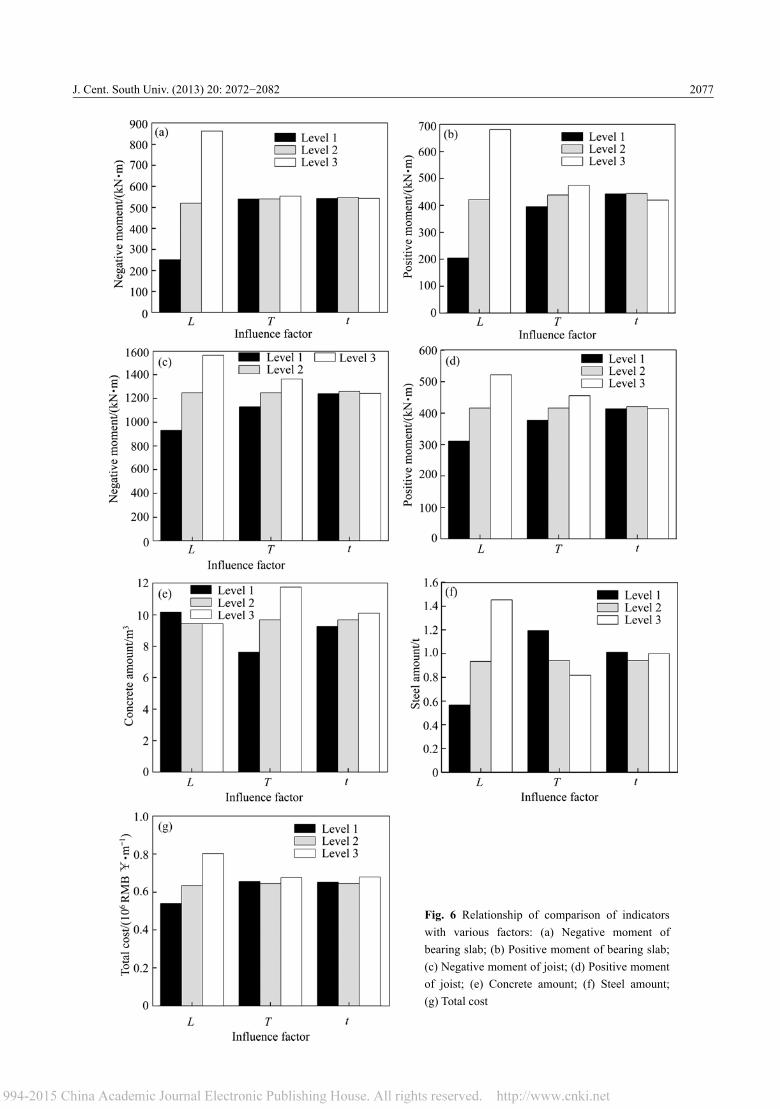
Seven objective function indexes are calculated forthe nine schemes, as shown in Fig. 6.
1) Span of bearing slab L
Span of bearing slab L has an important effect onsix objective function indexes (except concrete amount),and it is the best to take small value. While smaller spanshould increase the amount of piles and engineering cost,so it should not be too small. Since the largest span ofslab bridge should not exceed 10 m, the span of bearingslab should be 5−10 m.
2) Height of bearing slab THeight of the bearing plate T is the second most
important factor for the objective function, and theincrease of T will lead to increase of structural internalforce and increase of the amount of concrete. So, it isrecommended to be 0.8 m.
3) Height of joist tHeight of joist t has little effect on objective
function. Taking safety factor into consideration, it maybe appropriate to take a large value. Compared withbearing slab, joist has lower cost, whose cost is about11% of the bearing slab, therefore, it is not the key factorto determine the overall cost of the structure. In order toreduce the height of the structure, it is recommended tobe 0.8 m.
Pile length is determined by the thickness ofreinforced soil. Generally, pile should penetrate intoweak soil layer and fall on good soil layer, whichdepends on the requirement of the building design andengineering geological condition, and the design shouldmeet the requirement of the strength and deformation.For design of pile diameter, we should consider theengineering geological condition, piling equipment andconstruction technology and so on, and it is generally0.6−1.2 m. Transverse pile spacing should make thegravity center of train on the pile top.
2.5 Settlement computation method of pile−slabstructureThe settlement calculation of pile−slab structure
roadbed can generally use the theory of composite pilefoundation, and the total settlement is divided into twoparts: the compressive deformation of the reinforced areaand that of the soil below the reinforced area. When thepiles of pile−slab structure are rigid piles, thecompressive deformation of reinforced area can benegligible, and layer-wise summation method is usuallyused for the compressed volume of underlayer. Thebearing slab effect is not fully considered on thesettlement of soil between piles for the traditionalsettlement of pile foundation. The practice has provedthat it is significant for the reinforcement effect ofroadbed by using pile-slab structure, and compared toordinary pile foundation, pile−slab structure caneffectively control the subgrade settlement. While on thetheoretical side, it is still needed to scientifically explainits mechanism.
J. Cent. South Univ. (2013) 20: 2072−2082 2077
Fig. 6 Relationship of comparison of indicatorswith various factors: (a) Negative moment ofbearing slab; (b) Positive moment of bearing slab;(c) Negative moment of joist; (d) Positive momentof joist; (e) Concrete amount; (f) Steel amount;(g) Total cost
J. Cent. South Univ. (2013) 20: 2072−20822078
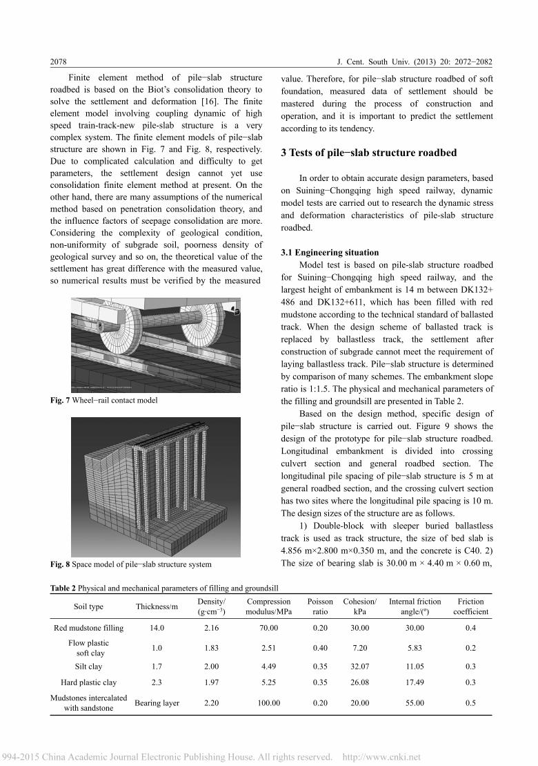
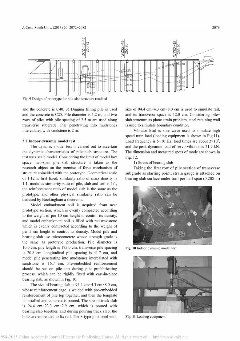
Finite element method of pile−slab structureroadbed is based on the Biot’s consolidation theory tosolve the settlement and deformation [16]. The finiteelement model involving coupling dynamic of highspeed train-track-new pile-slab structure is a verycomplex system. The finite element models of pile−slabstructure are shown in Fig. 7 and Fig. 8, respectively.Due to complicated calculation and difficulty to getparameters, the settlement design cannot yet useconsolidation finite element method at present. On theother hand, there are many assumptions of the numericalmethod based on penetration consolidation theory, andthe influence factors of seepage consolidation are more.Considering the complexity of geological condition,non-uniformity of subgrade soil, poorness density ofgeological survey and so on, the theoretical value of thesettlement has great difference with the measured value,so numerical results must be verified by the measured
Fig. 7Wheel−rail contact model
Fig. 8 Space model of pile−slab structure system
value. Therefore, for pile−slab structure roadbed of softfoundation, measured data of settlement should bemastered during the process of construction andoperation, and it is important to predict the settlementaccording to its tendency.
3 Tests of pile−slab structure roadbed
In order to obtain accurate design parameters, basedon Suining−Chongqing high speed railway, dynamicmodel tests are carried out to research the dynamic stressand deformation characteristics of pile-slab structureroadbed.
3.1 Engineering situationModel test is based on pile-slab structure roadbed
for Suining−Chongqing high speed railway, and thelargest height of embankment is 14 m between DK132+486 and DK132+611, which has been filled with redmudstone according to the technical standard of ballastedtrack. When the design scheme of ballasted track isreplaced by ballastless track, the settlement afterconstruction of subgrade cannot meet the requirement oflaying ballastless track. Pile−slab structure is determinedby comparison of many schemes. The embankment sloperatio is 1:1.5. The physical and mechanical parameters ofthe filling and groundsill are presented in Table 2.
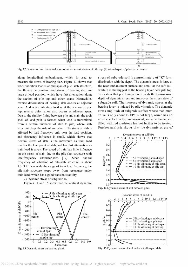
Based on the design method, specific design ofpile−slab structure is carried out. Figure 9 shows thedesign of the prototype for pile−slab structure roadbed.Longitudinal embankment is divided into crossingculvert section and general roadbed section. Thelongitudinal pile spacing of pile−slab structure is 5 m atgeneral roadbed section, and the crossing culvert sectionhas two sites where the longitudinal pile spacing is 10 m.The design sizes of the structure are as follows.
1) Double-block with sleeper buried ballastlesstrack is used as track structure, the size of bed slab is4.856 m×2.800 m×0.350 m, and the concrete is C40. 2)The size of bearing slab is 30.00 m × 4.40 m × 0.60 m,
Table 2 Physical and mechanical parameters of filling and groundsill
Soil type Thickness/m Density/(g·cm−3)
Compressionmodulus/MPa
Poissonratio
Cohesion/kPa
Internal frictionangle/(º)
Frictioncoefficient
Red mudstone filling 14.0 2.16 70.00 0.20 30.00 30.00 0.4
Flow plasticsoft clay 1.0 1.83 2.51 0.40 7.20 5.83 0.2
Silt clay 1.7 2.00 4.49 0.35 32.07 11.05 0.3
Hard plastic clay 2.3 1.97 5.25 0.35 26.08 17.49 0.3
Mudstones intercalatedwith sandstone Bearing layer 2.20 100.00 0.20 20.00 55.00 0.5
J. Cent. South Univ. (2013) 20: 2072−2082 2079
Fig. 9 Design of prototype for pile-slab structure roadbed
and the concrete is C40. 3) Digging filling pile is usedand the concrete is C25. Pile diameter is 1.2 m, and tworows of piles with pile spacing of 2.5 m are used alongtransverse subgrade. Pile penetrating into mudstonesintercalated with sandstone is 2 m.
3.2 Indoor dynamic model testThe dynamic model test is carried out to ascertain
the dynamic characteristics of pile−slab structure. Thetest uses scale model. Considering the limit of model boxspace, two-span pile−slab structure is taken as theresearch object on the premise of force mechanism ofstructure coincided with the prototype. Geometrical scaleof 1:12 is first fixed, similarity ratio of mass density is1:1, modulus similarity ratio of pile, slab and soil is 1:1,the reinforcement ratio of model slab is the same as theprototype, and other physical similarity ratio can bededuced by Bockingham π theorems.
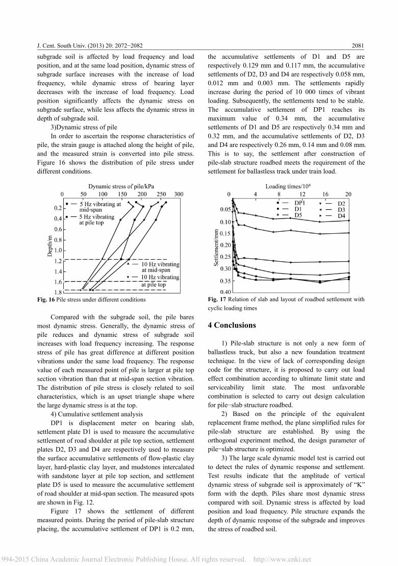
Model embankment soil is acquired from nearprototype section, which is evenly compacted accordingto the weight of per 10 cm height to control its density,and model embankment soil is filled with red mudstonewhich is evenly compacted according to the weight ofper 5 cm height to control its density. Model pile andbearing slab use microconcrete whose strength grade isthe same as prototype production. Pile diameter is10.0 cm, pile length is 175.0 cm, transverse pile spacingis 20.8 cm, longitudinal pile spacing is 41.7 cm, andmodel pile penetrating into mudstones intercalated withsandstone is 16.7 cm. Pre-embedded reinforcementshould be set on pile top during pile prefabricatingprocess, which can be rigidly fixed with cast-in-placebearing slab, as shown in Fig. 10.
The size of bearing slab is 94.4 cm×4.3 cm×8.0 cm,whose reinforcement cage is welded with pre-embeddedreinforcement of pile top together, and then the templateis installed and concrete is poured. The size of track slabis 94.4 cm×23.3 cm×2.9 cm, which is poured withbearing slab together, and during pouring track slab, thebolts are embedded to fix rail. The 8-type joist steel with
size of 94.4 cm×4.3 cm×8.0 cm is used to simulate rail,and its transverse space is 12.0 cm. Considering pile−slab structure as plane strain problem, steel retaining wallis used to simulate boundary condition.
Vibrator load is sine wave used to simulate highspeed train load (loading equipment is shown in Fig.11).Load frequency is 5−10 Hz, load times are about 2×10⁷,and the peak dynamic load of servo vibrator is 21.9 kN.The dimension and measured spots of mode are shown inFig. 12.
1) Stress of bearing slabTaking the first row of pile section of transverse
subgrade as starting point, strain gauge is attached onbearing slab surface under trail per half span (0.208 m)
Fig. 10 Indoor dynamic model test
Fig. 11 Loading equipment
J. Cent. South Univ. (2013) 20: 2072−20822080
Fig. 12 Dimension and measured spots of mode: (a) At section of pile top; (b) At mid-span of pile-slab structure
along longitudinal embankment, which is used tomeasure the stress of bearing slab. Figure 13 shows thatwhen vibration load is at mid-span of pile−slab structure,the flexure deformation and stress of bearing slab arelarge at load position, which have fast attenuation alongthe section of pile top and other spans. Meanwhile,reverse deformation of bearing slab occurs at adjacentspan. And when vibration load is at the section of piletop, reverse deformation also occurs at adjacent span.Due to the rigidity fixing between pile and slab, the archshell of load path is formed when load is transmittedfrom a certain thickness of slab to pile, where slabstructure plays the role of arch shell. The stress of slab isaffected by load frequency only near the load position,and frequency influence is small, which shows thatflexural stress of slab is the maximum as train loadreaches the load point of slab, and has fast attenuation astrain load is away. The speed of train has little influenceon the stress of slab, due to the pile-slab structure withlow-frequency characteristics [17]. Since naturalfrequency of vibration of pile-slab structure is about1.3−3.2 Hz outside the range of train load frequency, thepile-slab structure keeps away from resonance undertrain load, which has a good transient stability.
2) Dynamic stress of subgrade soilFigures 14 and 15 show that the vertical dynamic
Fig. 13 Dynamic stress on bearing plank
stress of subgrade soil is approximately of “K” formdistribution with the depth. The dynamic stress is large atthe near embankment surface and small at the soft soil,while it is the biggest at the bearing layer near pile top.Tests show that pile foundation expands the transmissiondepth of dynamic stress and improves the stress state ofsubgrade soil. The increase of dynamic stress at thebearing layer is induced by pile vibration. The dynamicstress amplitude of subgrade surface whose maximumvalue is only about 10 kPa is not large, which has noadverse effect on the embankment, so embankment soilfilled with red mudstone has not further to be treated.Further analysis shows that the dynamic stress of
Fig. 14 Dynamic stress of soil between piles
Fig. 15 Dynamic stress of soil under middle-span slab
J. Cent. South Univ. (2013) 20: 2072−2082 2081
subgrade soil is affected by load frequency and loadposition, and at the same load position, dynamic stress ofsubgrade surface increases with the increase of loadfrequency, while dynamic stress of bearing layerdecreases with the increase of load frequency. Loadposition significantly affects the dynamic stress onsubgrade surface, while less affects the dynamic stress indepth of subgrade soil.
3)Dynamic stress of pileIn order to ascertain the response characteristics of
pile, the strain gauge is attached along the height of pile,and the measured strain is converted into pile stress.Figure 16 shows the distribution of pile stress underdifferent conditions.
Fig. 16 Pile stress under different conditions
Compared with the subgrade soil, the pile baresmost dynamic stress. Generally, the dynamic stress ofpile reduces and dynamic stress of subgrade soilincreases with load frequency increasing. The responsestress of pile has great difference at different positionvibrations under the same load frequency. The responsevalue of each measured point of pile is larger at pile topsection vibration than that at mid-span section vibration.The distribution of pile stress is closely related to soilcharacteristics, which is an upset triangle shape wherethe large dynamic stress is at the top.
4) Cumulative settlement analysisDP1 is displacement meter on bearing slab,
settlement plate D1 is used to measure the accumulativesettlement of road shoulder at pile top section, settlementplates D2, D3 and D4 are respectively used to measurethe surface accumulative settlements of flow-plastic claylayer, hard-plastic clay layer, and mudstones intercalatedwith sandstone layer at pile top section, and settlementplate D5 is used to measure the accumulative settlementof road shoulder at mid-span section. The measured spotsare shown in Fig. 12.
Figure 17 shows the settlement of differentmeasured points. During the period of pile-slab structureplacing, the accumulative settlement of DP1 is 0.2 mm,
the accumulative settlements of D1 and D5 arerespectively 0.129 mm and 0.117 mm, the accumulativesettlements of D2, D3 and D4 are respectively 0.058 mm,0.012 mm and 0.003 mm. The settlements rapidlyincrease during the period of 10 000 times of vibrantloading. Subsequently, the settlements tend to be stable.The accumulative settlement of DP1 reaches itsmaximum value of 0.34 mm, the accumulativesettlements of D1 and D5 are respectively 0.34 mm and0.32 mm, and the accumulative settlements of D2, D3and D4 are respectively 0.26 mm, 0.14 mm and 0.08 mm.This is to say, the settlement after construction ofpile-slab structure roadbed meets the requirement of thesettlement for ballastless track under train load.
Fig. 17 Relation of slab and layout of roadbed settlement withcyclic loading times
4 Conclusions
1) Pile-slab structure is not only a new form ofballastless truck, but also a new foundation treatmenttechnique. In the view of lack of corresponding designcode for the structure, it is proposed to carry out loadeffect combination according to ultimate limit state andserviceability limit state. The most unfavorablecombination is selected to carry out design calculationfor pile−slab structure roadbed.
2) Based on the principle of the equivalentreplacement frame method, the plane simplified rules forpile-slab structure are established. By using theorthogonal experiment method, the design parameter ofpile−slab structure is optimized.
3) The large scale dynamic model test is carried outto detect the rules of dynamic response and settlement.Test results indicate that the amplitude of verticaldynamic stress of subgrade soil is approximately of “K”form with the depth. Piles share most dynamic stresscompared with soil. Dynamic stress is affected by loadposition and load frequency. Pile structure expands thedepth of dynamic response of the subgrade and improvesthe stress of roadbed soil.
J. Cent. South Univ. (2013) 20: 2072−20822082
References
[1] MAKRIS N, TAZOH T, YUNT X, FILL A C. Prediction of themeasured response of a scaled soil-pile-superstructure system [J].Soil Dynamics and Earthquake Engineering, 1997, 16: 113−124.
[2] KHODAIR Y A, HASSIOTIS S. Analysis of soil–pile interaction inintegral abutment [J]. Computers and Geotechnics, 2005, 32: 201−209.
[3] KELESOGLU M K, SPRINGMAN S M. Analytical and 3Dnumerical modelling of full-height bridge abutments constructed onpile foundations through soft soils [J]. Computers and Geotechnics,2011, 38: 934−948.
[4] ESVELD C, MARKINE V L. Assessment of high-speed slab trackdesign [J]. European Railway Review, 2006, 6: 44−50.
[5] ZHAN Yong-xiang, JIANG Guan-lu, NIU Guo-hui, WEI Yong-xing.Model experimental research on dynamic performance of pile-plankembankment [J]. Rock and Soil Mechanics, 2008, 29(8): 2097−2101.(in Chinese)
[6] HENDAWI S, FRANGOPOL D M. Design of composite hybridplate girder bridges based on reliability and optimization [J].Structural Safety, 1994, 15(1): 149−165.
[7] MALEKI S. Effect of deck and support stiffness on seismic responseof slab-girder bridges [J]. Engineering Structures, 2002, 24(2): 219−226.
[8] XU Qing-yuan, ZHANG Xu-jiu. Longitudinal forces characteristic ofBogl longitudinal connected ballastless track on high-speed railwaybridge [J]. Journal of Central South University: Science andTechnology, 2009, 40(2): 526−532. (in Chinese)
[9] ZHAI Wan-ming, CAI Cheng-biao, WANG Kai-yun. Mechanism and
model of high-speed train-track-bridge dynamic interaction [J].China Civil Engineering Journal, 2005, 38(11): 132−137. (inChinese)
[10] ZHAO Ming-hua, JIANG Chong, CAO Wen-gui, LIU Jian-hua.Catastrophic model for stability analysis of high pile-column bridgepier [J]. Journal of Central South University of Technology, 2007,14(5): 725−729.
[11] China Academy of Building Research. JGJ94-94 Technical Code forBuilding Pile Foundations [S]. Beijing: China Architecture &Building Press, 1995. (in Chinese)
[12] Ministry of Construction of People’s Republic of China. GB 50009—2001. Lode Code for the design of Building Structures [S]. Beijing:China Architecture & Building Press, 2002. (in Chinese)
[13] China Highway Planning and Design Institute. JTG D60-2004General Code for Design of Highway Bridges and Culverts [S].Beijing: China Communications Press, 2004. (in Chinese)
[14] TAN H C, FAMIYESIN O O R, IMBABI M S E. Dynamicdeformation signatures in reinforced concrete slabs for conditionmonitoring [J]. Computers and Structures, 2001, 79: 2413−2423.
[15] DING Zhao-feng. Plane simplified rules and analytical calculationfor pile-board structure of subgrade [J]. Journal of RailwayEngineering society, 2011, 155(8): 42−46.
[16] COMODROMOS E M, PAPADOPOULOU M C, RENTZEPERIS IK. Pile foundation analysis and design using experimental data and3-D numerical analysis [J]. Computers and Geotechnics, 2009, 36:819−836.
[17] LI Bao-jun, MA Kun-quan, ZHANG xin-xin. Study on dynamicproperty of pile-plank embankment used in high-speed railway withslab-track [J]. Journal of Shijiazhuang tiedao University: NaturalScience, 2011, 24(1): 63−68. (in Chinese)
(Edited by YANG Bing)