Embed Size (px)
Citation preview

AASHTO SCOBS T-14 Steel Structures Meeting June 2017
DESIGNING TWIN TUB GIRDER BRIDGES TO BE NON-FRACTURE CRITICALTwin Tub Task Group (T3)Texas Steel Quality Council
AASHTO SCOBS T-14 Steel Structures Meeting

AASHTO SCOBS T-14 Steel Structures Meeting June 2017
Texas Steel Quality Council
2
Texas Steel Quality Council (TSQC) – Established 1995– Joint owner-industry forum
– Meets annually
Twin Tub Task Group– Established in September 2016
– 17 Members from TSQC – TxDOT designers, inspectors, consultants, Fabricators, Researchers
– National Steel Bridge Alliance

AASHTO SCOBS T-14 Steel Structures Meeting June 2017
Table of contents
3
Twin Tub Task Group Goal
Precedents
Research Basis
Strength vs. Extreme Event Limit States
Proposed Agenda Item for Design
2
3
4
5
6
Expected Effect on Bridges7
Future Applications8
Background1

AASHTO SCOBS T-14 Steel Structures Meeting June 2017 4
BACKGROUND

AASHTO SCOBS T-14 Steel Structures Meeting June 2017
Background
5
Twin Tub Girders - All two girder bridges are defined as Fracture Critical (FC). June 2012 FHWA Memorandum,
“Clarification of Requirements for Fracture Critical Members”:– Introduced the new concept of System
Redundancy Member (SRM)
– New member classification: a member that requires fabrication according to the AWS FCP, but need not be considered a FCM for in-service inspection.
– SRMs should be designated on the design plans

AASHTO SCOBS T-14 Steel Structures Meeting June 2017 6
TWIN TUB TASK GROUP GOAL
AASHTO SCOBS T-14 Steel Structures Meeting June 2017
Twin Tub Task Group Goal
7
Develop LRFD-based design specifications which will allow twin tub girder bridges to be designed as SRM’s. Scope includes loads, analysis, design, detailing, materials,
fabrication and construction components Results can be incorporated into either AASHTO LRFD Bridge
Design Specifications, AASHTO Guide Specification or adopt requirements as part of TxDOT Bridge Design Manual Receive FHWA concurrence with the final recommendations &
deliverable

AASHTO SCOBS T-14 Steel Structures Meeting June 2017 8
PRECEDENTS
AASHTO SCOBS T-14 Steel Structures Meeting June 2017
Precedents
9
General Services Administration (GSA) – Buildings
Alternate Path Analysis & Design Guidelines for Progressive Collapse Resistance (October 2013) Progressive Collapse: defined as an
extent of damage or collapse that is disproportionate to the magnitude of the initiating event Extreme Event
AASHTO SCOBS T-14 Steel Structures Meeting June 2017
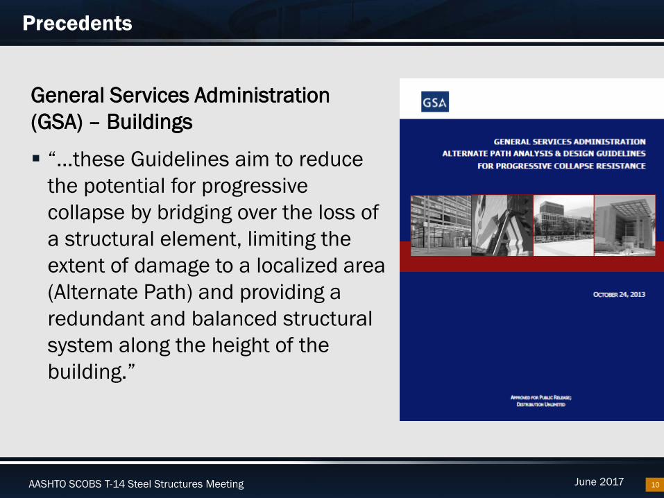
Precedents
10
General Services Administration (GSA) – Buildings
“…these Guidelines aim to reduce the potential for progressive collapse by bridging over the loss of a structural element, limiting the extent of damage to a localized area (Alternate Path) and providing a redundant and balanced structural system along the height of the building.”

AASHTO SCOBS T-14 Steel Structures Meeting June 2017
Precedents
11
General Services Administration (GSA) – Buildings
“The intent of these requirements is to distribute progressive collapse resistance up the height of the building without explicitly requiring column/wall removal scenarios at each level.”

AASHTO SCOBS T-14 Steel Structures Meeting June 2017
Precedents
12
General Services Administration (GSA) – Buildings
Allows for 3 levels of analysis procedures– Linear Static (LSP)– Nonlinear Static (NSP)– Nonlinear Dynamic (NDP)
Dependent on facility risk assessment

AASHTO SCOBS T-14 Steel Structures Meeting June 2017
Precedents
13
FHWA Guidelines for Cable-Stayed and Arch Bridges
Extreme Event Redundancy Required (Section B):
– “Long span bridges shall be designed such that controlled or sudden loss of a stay cable, individual hanger, or other structural element, will not cause collapse of the structure”
– “Tie girders…shall be designed for redundancy…may be accomplished through internal redundancy, external redundancy, or some combination of the two.”

AASHTO SCOBS T-14 Steel Structures Meeting June 2017
Precedents
14
FHWA Guidelines for Cable-Stayed and Arch Bridges
Load Combinations– 8.1.3.2 Loss of Structural Element
1.25DC + 1.5DW + 1.3 (LL + IM)
– 8.1.3.3 Loss of Stay Cable or Suspender 1.1DC + 1.35DW + 0.75(LL* + IM) + 1.1(cable loss or suspender dynamic forces)* Full LL placed in their actual striped lanes
– 8.5 Loss of Structural Elements1.5 minimum dynamic impact factor, regardless of analysisMinimum cable loss force = 1.5 x static force in cable from DL +LL

AASHTO SCOBS T-14 Steel Structures Meeting June 2017
Precedents
15
AASHTO LRFD for Cable-Stayed and Arch Bridges
Analysis requirements– AASHTO 4.6.3.7– Cable stay bridges shall be investigated for
the loss of any one cable stay.– Not prescriptive on analysis “means and
methods”

AASHTO SCOBS T-14 Steel Structures Meeting June 2017
Precedents
16
Pennsylvania DOT Design Manual (April 2015)
Section 3.4.1 Load Factors and Combinations– Extreme Event – Part of the Manual since 1996– Both are uncalibrated load combinations– Intended to force consideration of the safety of damaged structures
SYSTEM REDUNDANCY

AASHTO SCOBS T-14 Steel Structures Meeting June 2017
Precedents
17
Pennsylvania DOT Design Manual (April 2015)
Section 3.4.1 Load Factors and Combinations

AASHTO SCOBS T-14 Steel Structures Meeting June 2017
Precedents
18
Pennsylvania DOT Design Manual (April 2015)
Section 1.3.4 Redundancy [Two-girder Bridges]– Two girders can only be used if designed for redundancy – alternate load
paths– Approval of analysis is required (from Chief Bridge Engineer and FHWA)– 3D Analysis requirement - linear analysis

AASHTO SCOBS T-14 Steel Structures Meeting June 2017
Precedents
19
Pennsylvania DOT Design Manual (April 2015)
FHWA has already approved a newly designed bridge to contain SRM’s using an Extreme Event as the load case to analyze redundancy Members are designated on the plans as SRM’s and
fabricated according to AWS FCP.

AASHTO SCOBS T-14 Steel Structures Meeting June 2017 20
RESEARCH BASIS

AASHTO SCOBS T-14 Steel Structures Meeting June 2017
Research Basis
21
Modeling and Response of Fracture Critical Steel Box-Girder Bridges TxDOT Project 0-5498 (2010)
University of Texas at Austin Characterize the redundancy that exists in twin tub girder
bridges Developed guidelines for modeling behavior in the event of a
fracture of the tension flange Full-scale test with fractured bottom flange and web of outside
girder

AASHTO SCOBS T-14 Steel Structures Meeting June 2017
Research Basis
22
Modeling and Response of Fracture Critical Steel Box-Girder Bridges TxDOT Project 0-5498 (2010)
Full scale test Simulated Worst Case Simple Span 2 tub girders No external intermediate
diaphragms Horizontally curved Simulated HS20 over fracture

AASHTO SCOBS T-14 Steel Structures Meeting June 2017
Research Basis
1st Test – 5498 Project Linear shape-charge explosive Rapidly cut bottom flange Combination of analytical and full scale testing Equivalent of an HS-20 truck positioned directly above the fracture at the
most severe location The bridge deflected less than 1 inch
23
AASHTO SCOBS T-14 Steel Structures Meeting June 2017
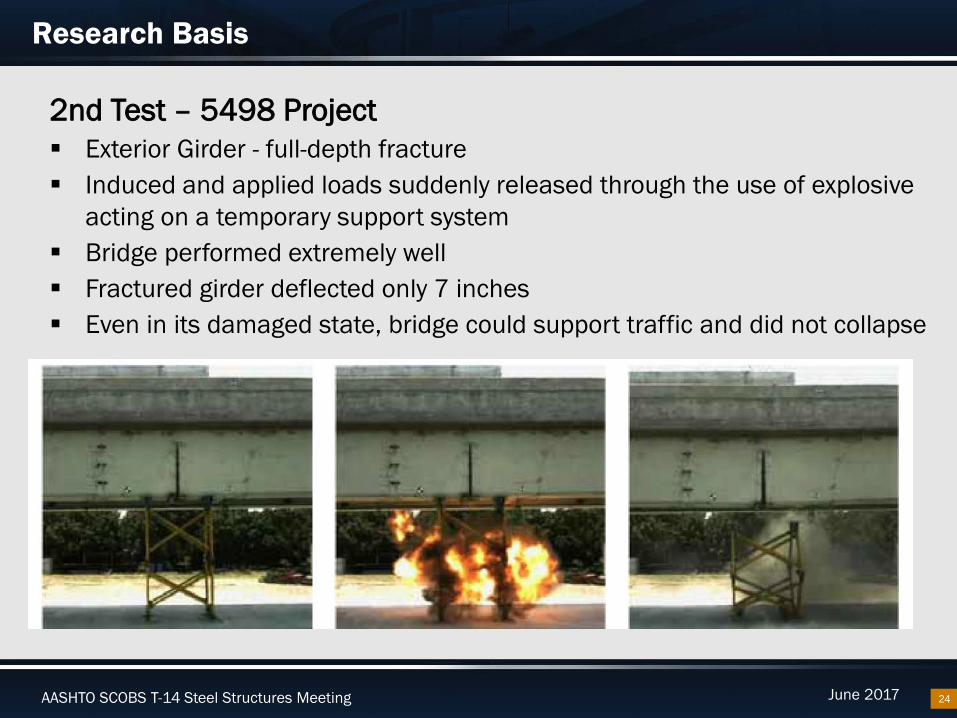
Research Basis
24
2nd Test – 5498 Project Exterior Girder - full-depth fracture Induced and applied loads suddenly released through the use of explosive
acting on a temporary support system Bridge performed extremely well Fractured girder deflected only 7 inches Even in its damaged state, bridge could support traffic and did not collapse

AASHTO SCOBS T-14 Steel Structures Meeting June 2017
Research Basis
25
3rd and Final Test – 5498 Project Conducted under statically applied loads Demonstrated that the bridge tested in the study was able to carry
363,000 lbs More than 5 times greater than a legal truck load

AASHTO SCOBS T-14 Steel Structures Meeting June 2017
Research Basis
26
TxDOT Project 0-5498 (2010)
Recommended, or allowed for, 3 levels of analysis– Simplified method– Yield line method– 3D FEA
Clearly demonstrated system redundancy for a span that was not specifically designed to have system redundancy Highlighted the importance of the deck and shear connectors
and their contribution to system performance Barrier railing was also observed to contribute structurally

AASHTO SCOBS T-14 Steel Structures Meeting June 2017 27
STRENGTH VS. EXTREME EVENT LIMIT STATE

AASHTO SCOBS T-14 Steel Structures Meeting June 2017
Strength vs. Extreme Event Limit States
28
Event is expected in life of structure (75 years)
Reliability Index = 3.5
Return period of event far exceeds expected life of bridge
Not calibrated for a reliability Index in AASHTO LRFD
There has been some research in this area, but not in LRFD
STRENGTH EXTREME EVENT

AASHTO SCOBS T-14 Steel Structures Meeting June 2017
Strength vs. Extreme Event Limit States
29
Steel Bridge Design Handbook: Limit StatesAuthor: Dennis Mertz
Section 6.0, Extreme Event Limit States– “[Extreme Event] limit states represent
loads or events of such great magnitude that to design for the levels of reliability or failure rates of the strength limit states would be economically prohibitive.”

AASHTO SCOBS T-14 Steel Structures Meeting June 2017 30
PROPOSED AGENDA ITEM FOR DESIGN

AASHTO SCOBS T-14 Steel Structures Meeting June 2017
Proposed Agenda Item for Design
31
1. Design bridge as normally done
2. Design bridge for member failure under Extreme Event, ф = 1.0

AASHTO SCOBS T-14 Steel Structures Meeting June 2017
Proposed Agenda Item for Design
32
1. Design bridge as normally done for the following limit states: Strength
– Use Redundancy Factor, ηR = 1.05
Service Fatigue & Fracture
– Infinite Fatigue Life

AASHTO SCOBS T-14 Steel Structures Meeting June 2017
Proposed Agenda Item for Design
33
2. Design bridge for member failure under Extreme Event
ф, Resistance Factor = 1.0, for Extreme Event Modified load factor for LL under Extreme Event II (1.0 for LL) Modified load factor for DC (1.1 for DC)
LOAD FACTORS

AASHTO SCOBS T-14 Steel Structures Meeting June 2017
Proposed Agenda Item for Design
34
2. Design bridge for member failure under Extreme Event
Multiple presence does not apply – otherwise 1.2 for one lane LL placed in striped traffic lane(s); none in striped shoulder LL set to HL-93 (truck or tandem + lane) LL is notional – meant to capture an envelope IM zeroed out for fracture event
LIVE LOAD
AASHTO SCOBS T-14 Steel Structures Meeting June 2017
Proposed Agenda Item for Design
35
2. Design bridge for member failure under Extreme Event
Allows for Simplified Strength check analysis– Conservative– Surviving girder carries full dead and live load
Refined method, but with exceptions Points the designer to check simple spans and end spans of
continuous units
ANALYSIS

AASHTO SCOBS T-14 Steel Structures Meeting June 2017
Proposed Agenda Item for Design
36
2. Design bridge for member failure under Extreme Event
Dynamic Increase Factor (DIF) set to 1.2 minimum– Commentary on strain rate– Strain rate can compensate for DIF, but probably only up to 10%
Uses same strength equations as Strength Limit State– Flexure– Shear/Torsion
NEW SECTION 6.11.12

AASHTO SCOBS T-14 Steel Structures Meeting June 2017
Proposed Agenda Item for Design
37
2. Design bridge for member failure under Extreme Event
Deck/stud connectors treated differently– Refer to Research Project 0-5498– AASHTO Article 6.16
(Provisions for seismic design - interaction equation)
– Deck performance likely the key item in this design process
NEW SECTION 6.11.12
Research 0-5498:

AASHTO SCOBS T-14 Steel Structures Meeting June 2017
Proposed Agenda Item for Design
38
2. Design bridge for member failure under Extreme Event
No checks required for Deformations or Deflections– Precedent set with cable-stayed/arch– Not included in the definition of Fracture Critical
NEW SECTION 6.11.12
AASHTO SCOBS T-14 Steel Structures Meeting June 2017
Proposed Agenda Item for Design
39
2. Design bridge for member failure under Extreme Event
Railing - use a structurally continuous rail HPS - encourage use Drain Holes - bottom flange (Cat D) omit 20ft either side of max
moment location Shear Studs – require to extend above bottom mat of reinf Deck Design– Do not allow the use of empirical deck
DETAILS

AASHTO SCOBS T-14 Steel Structures Meeting June 2017
Proposed Agenda Item for Design
40
2. Design bridge for member failure under Extreme Event
Deck Construction – do not allow the use of precast concrete panels (sub deck panels) Diaphragms - Require 2 “full-depth” diaphragms bracketing
max moment location if slab is not designed to support fractured girder Details - Restrict details within 20ft of maximum moment
location to Cat C′; this does not include secondary members, e.g. internal cross-frames
DETAILS

AASHTO SCOBS T-14 Steel Structures Meeting June 2017
Proposed Agenda Item for Design
41
2. Design bridge for member failure under Extreme Event
Substructure Strength and stability must be adequate to support the
superstructure during fracture and post-fracture Specify the use of anchor bolts or shear keys as required to
keep superstructure on the substructure Do not require bearings to meet rotation and compression
requirements due to fracture
DETAILS

AASHTO SCOBS T-14 Steel Structures Meeting June 2017
Proposed Agenda Item for Design
42
2. Design bridge for member failure under Extreme Event
Plans – Identify tension flanges and webs as System Redundant Members (SRMs) as defined in the FHWA June 2012 Memo
PLANS

AASHTO SCOBS T-14 Steel Structures Meeting June 2017
Proposed Agenda Item for Design
43
2. Design bridge for member failure under Extreme Event
Fabrication – fabricate SRMs according to the Fracture Control Plan (FCP – AWS D1.5)– Base Metal Requirements– Welding Processes and Procedures– Certification, Qualification, Inspection– Straightening, Curving and Cambering
FABRICATION

AASHTO SCOBS T-14 Steel Structures Meeting June 2017
Proposed Agenda Item for Design
44
2. Design bridge for member failure under Extreme Event
Construction stage – evaluate NCRs critically (commentary) Stud connector penetration above
bottom mat should be verified prior to deck placement, etc.
CONSTRUCTION

AASHTO SCOBS T-14 Steel Structures Meeting June 2017
Proposed Agenda Item for Design
45
Load FactorsPennDOT Extreme Event IV TSQC Extreme Event II
Redundancy Factor, nR 1.0 1.00DC: Dead Load 1.05 (0.95 min) 1.10 (0.9 min)DW: Dead Load 1.05 (0.90 min) 1.5Live Load 1.15 1.0Dynamic Increase Factor
None 1.2 (min); 1.3 (max)
ComparisonPennDOT Extreme Event IV TSQC Extreme Event II
Application of Live Load Placed in design lanes Placed in striped lanesLevel of Analysis Linear 3D analysis Allows for simplified conservative
analysis and Linear 3D analysisLL PHL-93 HL-93Impact IM = 33% IM = 0Deformations/ Deflections
No checks required – objective of analysis is survival of the bridge
No checks required
Calibration Uncalibrated – intended to force consideration of damaged structures
Uncalibrated

AASHTO SCOBS T-14 Steel Structures Meeting June 2017
Proposed Agenda Item for Design
46
Where we are:
Minor revisions are needed in order to update the proposed Agenda Item Fracture Critical Workshop (NSBA) on May 1st
– Load factors were discussed – more work is slated to be done– Dynamic Increase Factor (DIF) – discussions were in the range of 1.2 to
1.3
Take two examples and analyze them with the TSQC approach to see if it controls the design (if so, how much)

AASHTO SCOBS T-14 Steel Structures Meeting June 2017 47
EXPECTED EFFECT ON BRIDGES

AASHTO SCOBS T-14 Steel Structures Meeting June 2017
Expected Effect on Bridges
48
Inspections Decrease number of
Fracture Critical Inspections– Hands on inspections will
not be required– Increase safety – most
inspections are done at night
– Decrease disruption to traffic
2 year Routine Inspections will continue

AASHTO SCOBS T-14 Steel Structures Meeting June 2017 49
FUTURE APPLICATIONS

AASHTO SCOBS T-14 Steel Structures Meeting June 2017
Future Applications
50
Other members currently identified as Fracture Critical– Steel box Straddle bents

AASHTO SCOBS T-14 Steel Structures Meeting June 2017
Acknowledgements
51
John Holt, HDR Greg Turco, TxDOT Bridge Division Mike Grubb, M.A. Grubb Associates Texas Steel Quality Council Texas Twin Tub Task Group Members National Steel Bridge Alliance Tom Macioce, Pennsylvania DOT

AASHTO SCOBS T-14 Steel Structures Meeting June 2017
Questions
52

AASHTO SCOBS T-14 Steel Structures Meeting June 2017
Copyright notice
53
Copyright 2017 • Texas Department of Transportation • All Rights Reserved
Entities or individuals that copy and present state agency information must identify the source of the content, including the date the content was copied. Entities or individuals that copy and present state agency information on their websites must accompany that information with a statement that neither the entity or individual nor the information, as it is presented on its website, is endorsed by the State of Texas or any state agency. To protect the intellectual property of state agencies, copied information must reflect the copyright, trademark, service mark, or other intellectual property rights of the state agency whose protected information is being used by the entity or individual. Entities or individuals may not copy, reproduce, distribute, publish, or transmit, in any way this content for commercial purposes. This presentation is distributed without profit and is being made available solely for educational purposes. The use of any copyrighted material included in this presentation is intended to be a “fair use” of such material as provided for in Title 17 U.S.C. Section 107 of the US Copyright Law.


![Micro pavimentos+fhwa--sa-94-051[1]](https://img.pdfslide.tips/doc/110x75/547cc780b37959532b8b50cd/micro-pavimentosfhwa-sa-94-0511.jpg)