Embed Size (px)
Citation preview
8/18/2019 FL_DCMDS_2.0.3_LG(1).pdf
http://slidepdf.com/reader/full/fldcmds203lg1pdf 1/482
DCMDS
Implementing
Cisco MDS Version 2.0
Fast Lane LAB Guide
Version 2.0.3 (for MDS SuperPod)

8/18/2019 FL_DCMDS_2.0.3_LG(1).pdf
http://slidepdf.com/reader/full/fldcmds203lg1pdf 2/482
2 Configuring Cisco MDS 9000 Series Switches (DCMDS) v2.0 © 2014 Fast Lane and Cisco Systems, Inc.
ATTENTION The Information contained in this guide is intended for training purposes only. This guide contains information and activities that, while beneficial for
purposes of training in a close, non-production environment, can result in downtime or other severe consequences and therefore are not intended as a
reference guide. This guide is not a technical reference and should not, under any circumstances be used in a production environment. Customers
should refer to the published specifications applicable to specific products for technical information. The information in this guide is distributed ASIS, and the use of this information or implementation of any recommendations or techniques herein is a customer’s responsibility.
COPYRIGHT
© 2014 Fast Lane GmbH. All rights reserved.
All other brands and product names are trademarks of their respective owners. No part of this book covered by copyright may be reproduced in any form or by any means (graphic, electronic, or mechanical, including photocopying, recording, taping, or storage in an electronic retrieval system) without prior written permission of the copyright owner.
Fast Lane reserves the right to change any products described herein at any time and without notice. Fast Lane assumes no responsibility or liabilityarising from the use of products or materials described herein, except as expressly agreed to in writing by Fast Lane. The use or purchase of this
product or materials does not convey a license under any patent rights, trademark rights, or any other intellectual property rights of Fast Lanehe
product described in this manual may be protected by one or more patents, foreign patents, or pending applications.
8/18/2019 FL_DCMDS_2.0.3_LG(1).pdf
http://slidepdf.com/reader/full/fldcmds203lg1pdf 3/482
Configuring Cisco MDS 9000 Series Switches (DCMDS) v2.0 Fast Lane Lab Guide 2.0.3 3
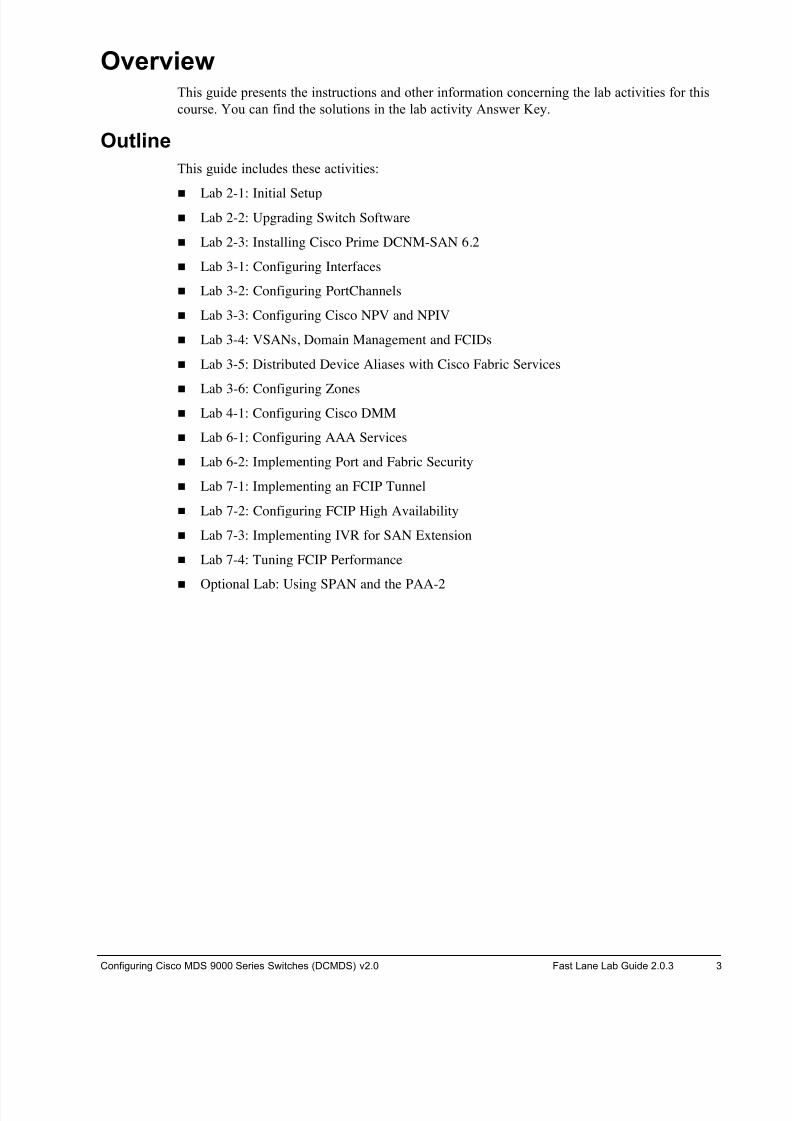
Overview This guide presents the instructions and other information concerning the lab activities for this
course. You can find the solutions in the lab activity Answer Key.
Outline
This guide includes these activities:
! Lab 2-1: Initial Setup
! Lab 2-2: Upgrading Switch Software
! Lab 2-3: Installing Cisco Prime DCNM-SAN 6.2
! Lab 3-1: Configuring Interfaces
! Lab 3-2: Configuring PortChannels
! Lab 3-3: Configuring Cisco NPV and NPIV
! Lab 3-4: VSANs, Domain Management and FCIDs
! Lab 3-5: Distributed Device Aliases with Cisco Fabric Services
! Lab 3-6: Configuring Zones
! Lab 4-1: Configuring Cisco DMM
! Lab 6-1: Configuring AAA Services
! Lab 6-2: Implementing Port and Fabric Security
! Lab 7-1: Implementing an FCIP Tunnel
! Lab 7-2: Configuring FCIP High Availability
! Lab 7-3: Implementing IVR for SAN Extension
! Lab 7-4: Tuning FCIP Performance
! Optional Lab: Using SPAN and the PAA-2
8/18/2019 FL_DCMDS_2.0.3_LG(1).pdf
http://slidepdf.com/reader/full/fldcmds203lg1pdf 4/482
4 Configuring Cisco MDS 9000 Series Switches (DCMDS) v2.0 © 2014 Fast Lane and Cisco Systems, Inc.
DCMDS .................................................................................................................................1
Overview ..................................................................................................................................... 3
Outline .................................................................................................................................................. 3
Lab Information .......................................................................................................................... 8
Lab Topology (one Sub-Pod for 2 Students) ........................................................................................ 8
Usernames and passwords .................................................................................................................. 9
IP addressing ..................................................................................................................................... 10
Lab 0: the FastLane Remote Lab............................................................................................ 11
Task 1: FastLane remote lab login ..................................................................................................... 11
Task 2: FastLane remote lab device management ............................................................................ 12
Task 3: FastLane remote device access ............................................................................................ 13
Lab 2-1: Initial Setup ................................................................................................................ 14
Activity Objective ................................................................................................................................ 14
Visual Objective .................................................................................................................................. 14
Required Resources ........................................................................................................................... 14
Command List .................................................................................................................................... 15
Task 1: Complete the Initial Switch Configuration .............................................................................. 16
Task 2: Examine the MDS Environment ............................................................................................ 21
Lab 2-2: Upgrading Switch Software ..................................................................................... 27
Activity Objective ................................................................................................................................ 27
Required Resources ........................................................................................................................... 27
Command List .................................................................................................................................... 28
Task 1: Troubleshoot Software Version Conflicts .............................................................................. 29
Task 2: Troubleshoot the Boot Process ............................................................................................. 34
Task 3: Upgrade Switch Software ...................................................................................................... 44
Task 3: Cleanup ................................................................................................................................. 49
Lab 2-3: Install Cisco Prime DCNM 6.2 .................................................................................. 50
Activity Objective ................................................................................................................................ 50
Task 1: Install Cisco DCNM SAN ....................................................................................................... 51
Lab 3-1: Configuring Interfaces .............................................................................................. 63
Activity Objective ................................................................................................................................ 63
Visual Objective .................................................................................................................................. 63
Required Resources ........................................................................................................................... 64
Command List .................................................................................................................................... 64
Task 1: Complete the Initial Switch Configuration .............................................................................. 65
Task 2: Configure Fx_Ports ................................................................................................................ 67
Task 3: Configure E_Ports ................................................................................................................. 70
Task 4: Configure E and TE Ports ...................................................................................................... 73
Task 5: Connecting to a 9710 director ............................................................................................... 81
Task 6: Display the FLOGI and FCNS Databases ........................................................................... 107
Task 6: Cleanup ............................................................................................................................... 109
Lab 3-2: Configuring PortChannels ..................................................................................... 111
Activity Objective .............................................................................................................................. 111
Visual Objective ................................................................................................................................ 111
Required Resources ......................................................................................................................... 112 Command List .................................................................................................................................. 112
Task 1: Complete the Initial Switch Configuration ............................................................................ 114
Task 2: Manually Create a PortChannel .......................................................................................... 121
Task 3: Use the PortChannel Wizard ............................................................................................... 127
Task 4: Demonstrate the Benefit of Port Channeling with FSPF ..................................................... 131
Task 5: Cleanup ............................................................................................................................... 135
8/18/2019 FL_DCMDS_2.0.3_LG(1).pdf
http://slidepdf.com/reader/full/fldcmds203lg1pdf 5/482
Configuring Cisco MDS 9000 Series Switches (DCMDS) v2.0 Fast Lane Lab Guide 2.0.3 5
Lab 3-3: Configuring Cisco NPV and NPIV .......................................................................... 139
Activity Objective .............................................................................................................................. 139
Visual Objective ................................................................................................................................ 139
Required Resources ......................................................................................................................... 139
Command List .................................................................................................................................. 140
Task 1: Complete the Initial Switch Configuration ............................................................................ 141
Task 2: Configure NPV ..................................................................................................................... 143
Task 3: Verify NPIV .......................................................................................................................... 145
Task 4: Display the FLOGI and FCNS Databases with NPV ........................................................... 150
Task 5: Configure Trunking F-port PortChannel ............................................................................... 152
Task 6: Cleanup ............................................................................................................................... 158
Lab 3-4: VSANs, Domain Management and FCIDs ............................................................. 160
Activity Objective .............................................................................................................................. 160
Visual Objective ................................................................................................................................ 160
Required Resources ......................................................................................................................... 161
Command List .................................................................................................................................. 161
Task 1: Complete the Initial Switch Configuration ............................................................................ 162
Task 2: Create VSANs and Implement Redundant Fabrics ............................................................. 165
Task 3: Understand the Isolated VSAN ............................................................................................ 171
Task 4: Configure Domain IDs ......................................................................................................... 174
Task 3: Purging Persistent FCIDs .................................................................................................... 183
Task 4: Configure Static FCIDs ........................................................................................................ 185
Task 5: Cleanup ............................................................................................................................... 187
Lab 3-5: Distributed Device Aliases with Cisco Fabric Services ...................................... 190
Activity Objective .............................................................................................................................. 190
Visual Objective ................................................................................................................................ 190
Required Resources ......................................................................................................................... 190
Command List .................................................................................................................................. 191
Task 1: Complete the Initial Switch Configuration ............................................................................ 192
Task 2: Configure, Merge, and Distribute Device Aliases ................................................................ 195
Task 3: Cleanup ............................................................................................................................... 202
Lab 3-6: Configuring Zones .................................................................................................. 203
Activity Objective .............................................................................................................................. 203
Visual Objective ................................................................................................................................ 203
Command List .................................................................................................................................. 204 Task 1: Complete the Initial Switch Configuration ............................................................................ 206
Task 2: Create Device Aliases ......................................................................................................... 213
Task 3: Create Zones and Zone Sets ............................................................................................... 217
Task 4: Activate Zonesets ................................................................................................................ 222
Task 5: Using a FC disk ................................................................................................................... 227
Task 6: Configure Active Zoneset Distribution ................................................................................. 229
Task 7: Configure Full Zoneset Distribution ..................................................................................... 233
Task 8: Merge Zones ........................................................................................................................ 234
Task 9: Manage Zone Sets .............................................................................................................. 238
Task 10: Configure Smart Zoning ..................................................................................................... 243
Task 11: Cleanup ............................................................................................................................. 246
Lab 4-1: Configuring Cisco DMM ......................................................................................... 250
Activity Objective .............................................................................................................................. 250
Visual Objective ................................................................................................................................ 250
Required Resources ......................................................................................................................... 251
Command List .................................................................................................................................. 251
Task 1: Setup ................................................................................................................................... 252
Task 2: Verify the DMM Feature ....................................................................................................... 259
Task 3: Preconfiguration for DMM .................................................................................................... 263
Task 4: Configure DMM for a Data Mobility Job ............................................................................... 267
Task 5: Run a Cisco DMM Job ......................................................................................................... 273
Task 6: Terminate and Delete a Data Mobility Job ........................................................................... 276
Task 7: Cleanup ............................................................................................................................... 277
8/18/2019 FL_DCMDS_2.0.3_LG(1).pdf
http://slidepdf.com/reader/full/fldcmds203lg1pdf 6/482
6 Configuring Cisco MDS 9000 Series Switches (DCMDS) v2.0 © 2014 Fast Lane and Cisco Systems, Inc.
Lab 6-1: Configuring AAA Services ..................................................................................... 281
Activity Objective .............................................................................................................................. 281
Visual Objective ................................................................................................................................ 281
Required Resources ......................................................................................................................... 282
Command List .................................................................................................................................. 282
Task Overview .................................................................................................................................. 282
Task 1: Complete the Initial Switch Configuration ............................................................................ 283
Task 2: Configure a RADIUS Server ................................................................................................ 285
Task 3: Configure RADIUS AAA Services on the Cisco MDS 9000 ................................................ 305
Task 4: Configure AAA Server Monitoring ....................................................................................... 311
Task 5: Cleanup ............................................................................................................................... 313
Lab 6-2: Implementing Port and Fabric Security ................................................................ 314
Activity Objective .............................................................................................................................. 314
Visual Objective ................................................................................................................................ 314
Required Resources ......................................................................................................................... 314
Command List .................................................................................................................................. 315
Task Overview .................................................................................................................................. 315
Task 1: Complete the Initial Switch Configuration ............................................................................ 316
Task 2: Configure Port Security ....................................................................................................... 318
Task 3: Configure Fabric Binding for Fibre Channel VSANs ............................................................ 326
Task 4: Implement DH-CHAP .......................................................................................................... 331
Task 5: Create IP Access Lists ........................................................................................................ 341
Task 6: Cleanup ............................................................................................................................... 344
Lab 7-1: Implementing an FCIP Tunnel ................................................................................ 348
Activity Objective .............................................................................................................................. 348
Visual Objective ................................................................................................................................ 348
Required Resources ......................................................................................................................... 350
Command List .................................................................................................................................. 351
Task 1: Complete the Initial Switch Configuration ............................................................................ 352
Task 2: Configure Gigabit Ethernet Interfaces ................................................................................. 360
Task 3: Configure an FCIP Profile .................................................................................................... 364
Task 4: Create an FCIP Tunnel ........................................................................................................ 368
Task 5: Implement Zoning ................................................................................................................ 372
Task 6: Create and Test a File System ............................................................................................ 376
Task 7: Cleanup ............................................................................................................................... 379
Lab 7-2: Configuring FCIP High Availability ........................................................................ 384
Activity Objective .............................................................................................................................. 384
Visual Objective ................................................................................................................................ 384
Required Resources ......................................................................................................................... 384
Command List .................................................................................................................................. 385
Task 1: Complete the Initial Switch Configuration ............................................................................ 386
Task 2: Configure a FCIP Tunnel ..................................................................................................... 393
Task 3: Create an FCIP PortChannel ............................................................................................... 398
Task 4: Cleanup ............................................................................................................................... 401
Lab 7-3: Implementing IVR for SAN Extension ................................................................... 406
Activity Objective .............................................................................................................................. 406
Visual Objective ................................................................................................................................ 406
Required Resources ......................................................................................................................... 406
Command List .................................................................................................................................. 407
Task 1: Complete the Initial Switch Configuration ............................................................................ 409
Task 2: Create an FCIP Tunnels and Aggregate the FCIP Link into a PortChannel ........................ 416
Task 3: Configure IVR ...................................................................................................................... 423
Task 4: Cleanup ............................................................................................................................... 434
8/18/2019 FL_DCMDS_2.0.3_LG(1).pdf
http://slidepdf.com/reader/full/fldcmds203lg1pdf 7/482
Configuring Cisco MDS 9000 Series Switches (DCMDS) v2.0 Fast Lane Lab Guide 2.0.3 7
Lab 7-4: Tuning FCIP Performance ...................................................................................... 439
Activity Objective .............................................................................................................................. 439
Visual Objective ................................................................................................................................ 439
Required Resources ......................................................................................................................... 439
Command List .................................................................................................................................. 440
Task 1: Complete the Initial Switch Configuration ............................................................................ 442
Task 2: Configure the FCIP Tunnel and Tune Down TCP Parameters ............................................ 445
Task 3: Document Performance Measurements .............................................................................. 450
Task 4: Tune TCP Parameters ......................................................................................................... 458
Task 4: Cleanup ............................................................................................................................... 463
Optional Lab: Using SPAN and the Cisco Port Analyzer Adapter .................................... 467
Activity Objective .............................................................................................................................. 467
Visual Objective ................................................................................................................................ 467
Required Resources ......................................................................................................................... 468
Command List .................................................................................................................................. 468
Task 1: Complete the Initial Switch Configuration ............................................................................ 469
Task 2: Configure SPAN Ports ......................................................................................................... 471
Task 3: Create a SPAN Session ...................................................................................................... 474
Task 4: Viewing Captured Traffic ..................................................................................................... 478
Task 5 (optional): Analyze Fibre Channel Traffic ............................................................................. 481
Task 6: Cleanup ............................................................................................................................... 483
8/18/2019 FL_DCMDS_2.0.3_LG(1).pdf
http://slidepdf.com/reader/full/fldcmds203lg1pdf 8/482
8 Configuring Cisco MDS 9000 Series Switches (DCMDS) v2.0 © 2014 Fast Lane and Cisco Systems, Inc.
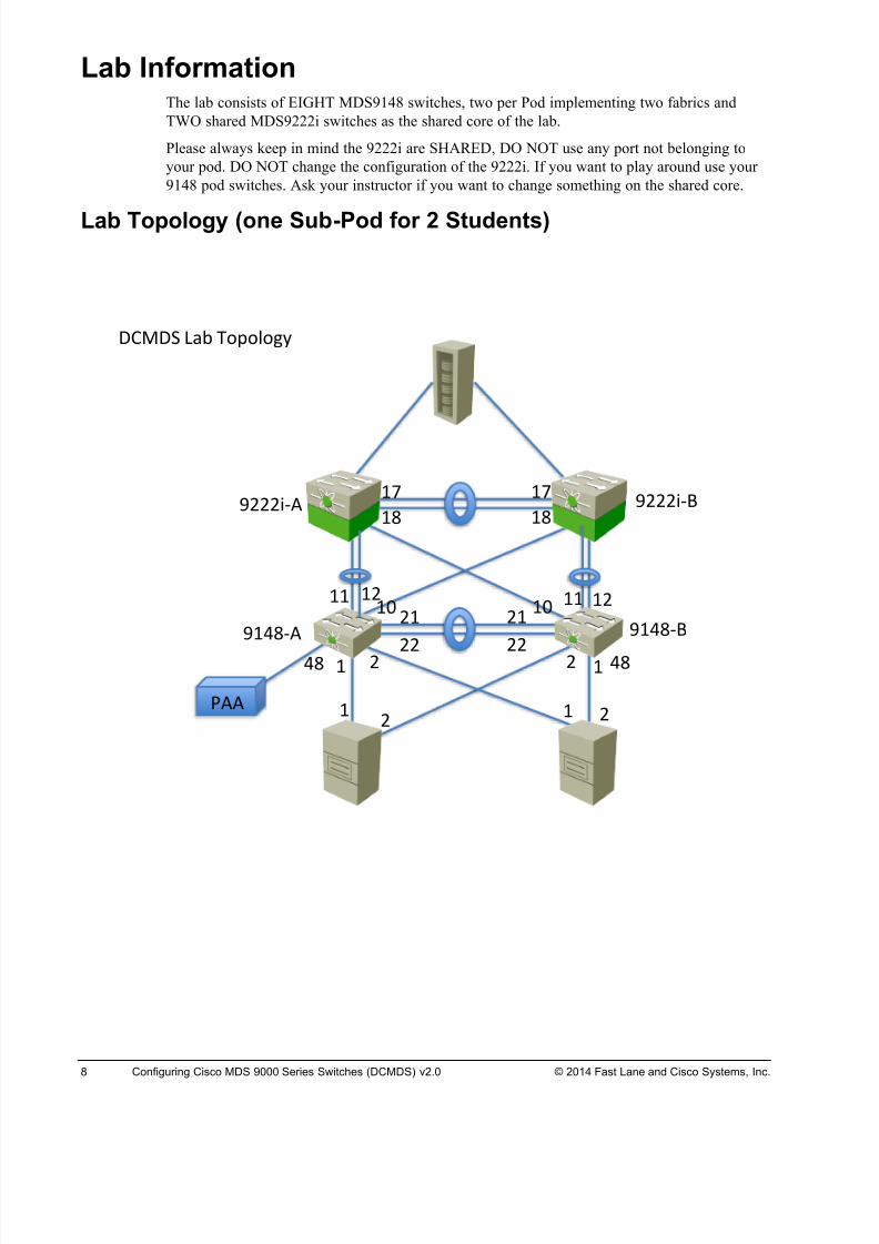
Lab Information The lab consists of EIGHT MDS9148 switches, two per Pod implementing two fabrics and
TWO shared MDS9222i switches as the shared core of the lab.
Please always keep in mind the 9222i are SHARED, DO NOT use any port not belonging to
your pod. DO NOT change the configuration of the 9222i. If you want to play around use your
9148 pod switches. Ask your instructor if you want to change something on the shared core.
Lab Topology
(one Sub-Pod for 2 Students)
! !# #
!# !! !#!!#!
##
#!
##
!# #!
!$ !$
%!&'() %!&'(*
%###+() %###+(*!,
!'
!,
!'
-))
&'&'
./0.1 234 5676869:
8/18/2019 FL_DCMDS_2.0.3_LG(1).pdf
http://slidepdf.com/reader/full/fldcmds203lg1pdf 9/482
Configuring Cisco MDS 9000 Series Switches (DCMDS) v2.0 Fast Lane Lab Guide 2.0.3 9
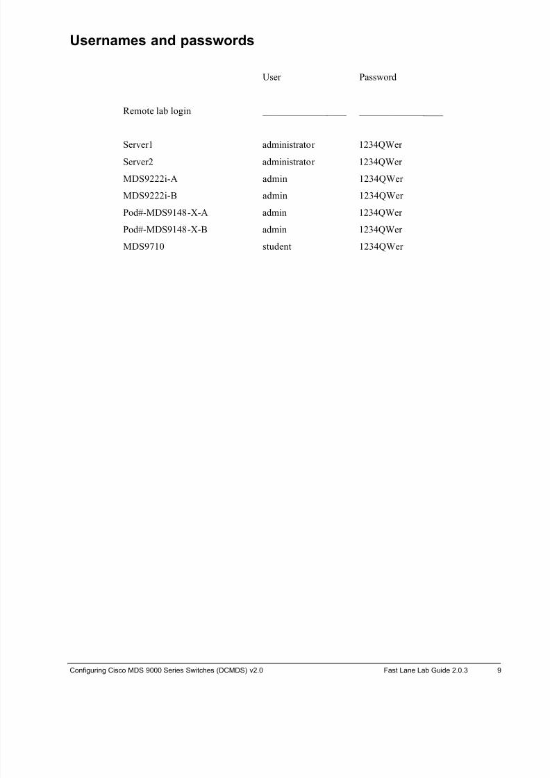
Usernames and passwords
User Password
Remote lab login _________________ _________________
Server1 administrator 1234QWer
Server2 administrator 1234QWer
MDS9222i-A admin 1234QWer
MDS9222i-B admin 1234QWer
Pod#-MDS9148-X-A admin 1234QWer
Pod#-MDS9148-X-B admin 1234QWer
MDS9710 student 1234QWer
8/18/2019 FL_DCMDS_2.0.3_LG(1).pdf
http://slidepdf.com/reader/full/fldcmds203lg1pdf 10/482
10 Configuring Cisco MDS 9000 Series Switches (DCMDS) v2.0 © 2014 Fast Lane and Cisco Systems, Inc.
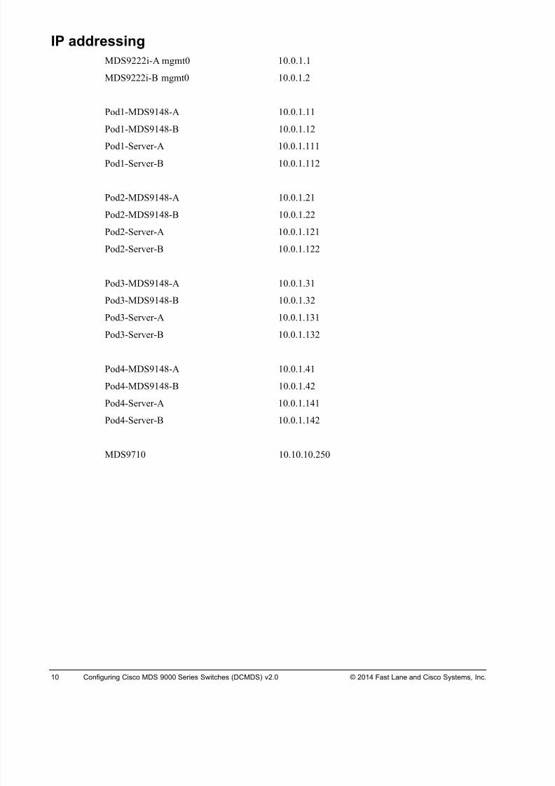
IP addressing
MDS9222i-A mgmt0 10.0.1.1
MDS9222i-B mgmt0 10.0.1.2
Pod1-MDS9148-A 10.0.1.11
Pod1-MDS9148-B 10.0.1.12
Pod1-Server-A 10.0.1.111
Pod1-Server-B 10.0.1.112
Pod2-MDS9148-A 10.0.1.21
Pod2-MDS9148-B 10.0.1.22
Pod2-Server-A 10.0.1.121
Pod2-Server-B 10.0.1.122
Pod3-MDS9148-A 10.0.1.31
Pod3-MDS9148-B 10.0.1.32
Pod3-Server-A 10.0.1.131
Pod3-Server-B 10.0.1.132
Pod4-MDS9148-A 10.0.1.41
Pod4-MDS9148-B 10.0.1.42
Pod4-Server-A 10.0.1.141
Pod4-Server-B 10.0.1.142
MDS9710 10.10.10.250
8/18/2019 FL_DCMDS_2.0.3_LG(1).pdf
http://slidepdf.com/reader/full/fldcmds203lg1pdf 11/482
Configuring Cisco MDS 9000 Series Switches (DCMDS) v2.0 Fast Lane Lab Guide 2.0.3 11
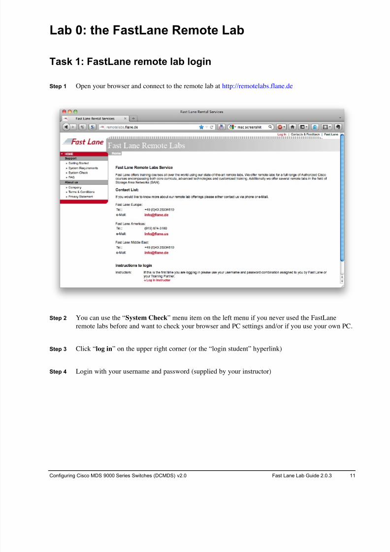
Lab 0: the FastLane Remote Lab
Task 1: FastLane remote lab login
Step 1 Open your browser and connect to the remote lab at http://remotelabs.flane.de
Step 2 You can use the “System Check” menu item on the left menu if you never used the FastLane
remote labs before and want to check your browser and PC settings and/or if you use your own PC.
Step 3 Click “log in” on the upper right corner (or the “login student” hyperlink)
Step 4 Login with your username and password (supplied by your instructor)
8/18/2019 FL_DCMDS_2.0.3_LG(1).pdf
http://slidepdf.com/reader/full/fldcmds203lg1pdf 12/482
12 Configuring Cisco MDS 9000 Series Switches (DCMDS) v2.0 © 2014 Fast Lane and Cisco Systems, Inc.
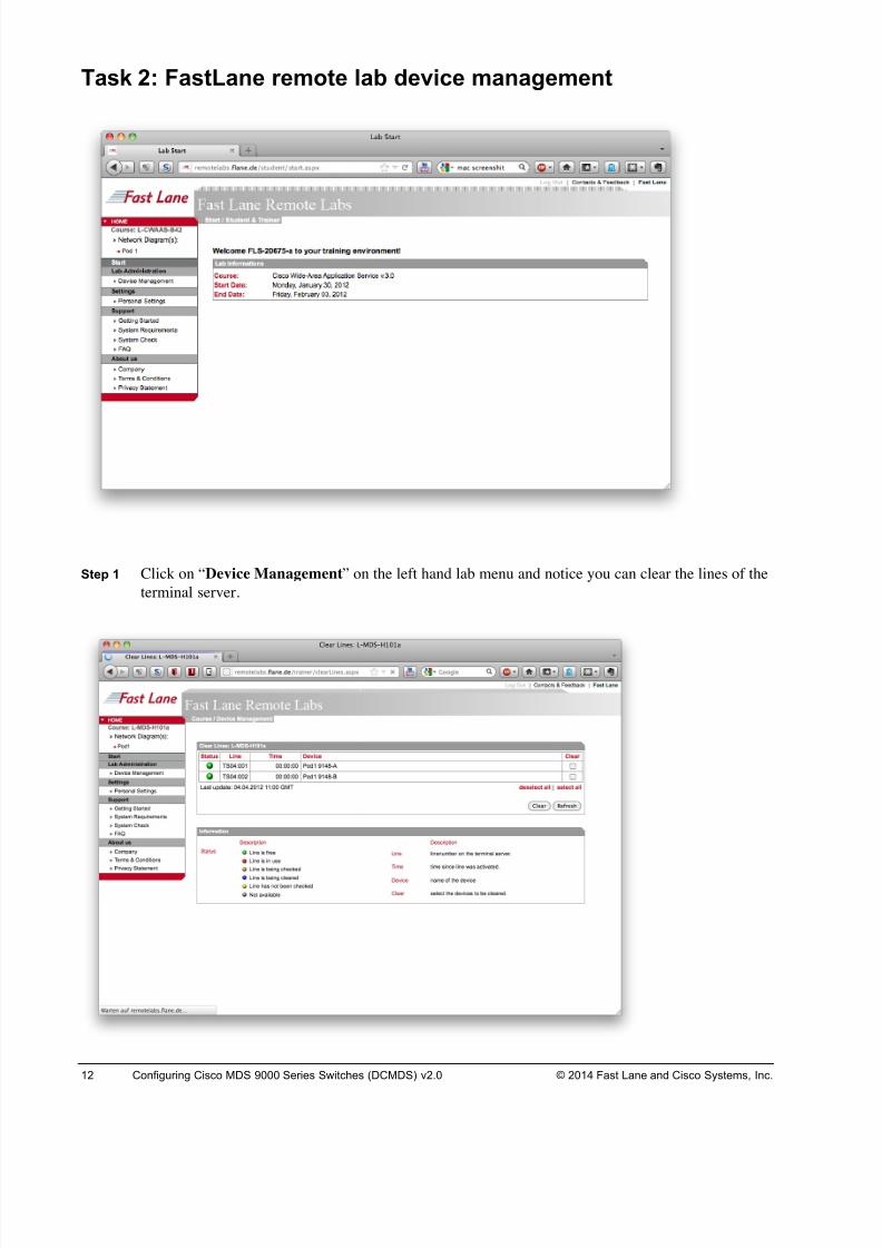
Task 2: FastLane remote lab device management
Step 1 Click on “Device Management” on the left hand lab menu and notice you can clear the lines of the
terminal server.
8/18/2019 FL_DCMDS_2.0.3_LG(1).pdf
http://slidepdf.com/reader/full/fldcmds203lg1pdf 13/482
Configuring Cisco MDS 9000 Series Switches (DCMDS) v2.0 Fast Lane Lab Guide 2.0.3 13
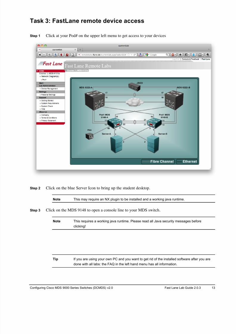
Task 3: FastLane remote device access
Step 1 Click at your Pod# on the upper left menu to get access to your devices
Step 2 Click on the blue Server Icon to bring up the student desktop.
Note This may require an NX plugin to be installed and a working java runtime.
Step 3 Click on the MDS 9148 to open a console line to your MDS switch.
Note This requires a working java runtime. Please read all Java security messages before
clicking!
Tip If you are using your own PC and you want to get rid of the installed software after you are
done with all labs: the FAQ in the left hand menu has all information.
8/18/2019 FL_DCMDS_2.0.3_LG(1).pdf
http://slidepdf.com/reader/full/fldcmds203lg1pdf 14/482
14 Configuring Cisco MDS 9000 Series Switches (DCMDS) v2.0 © 2014 Fast Lane and Cisco Systems, Inc.
Lab 2-1: Initial Setup Complete this lab activity to practice what you learned in the related lesson.
Activity Ob jective
In this activity, you will perform the initial switch configuration process so that the switch can
be accessed from the management network. After completing this activity, you will be able to
meet these objectives:
! Use the CLI to complete the initial switch configuration process
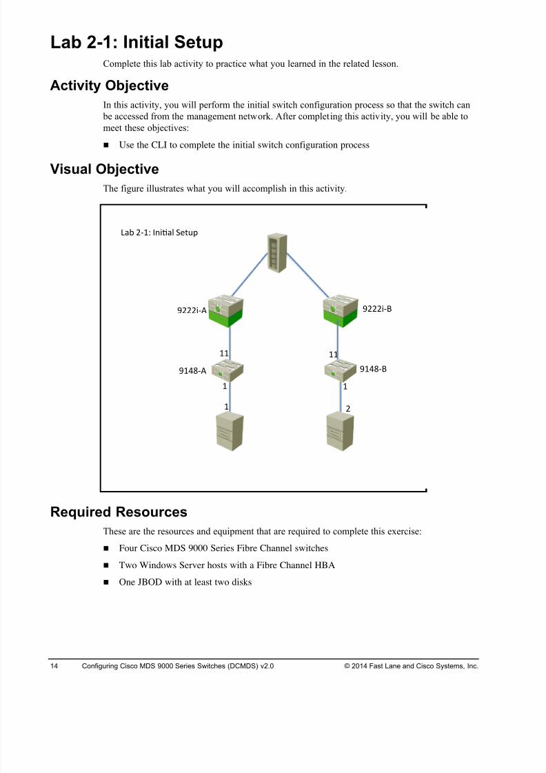
Visual Objective
The figure illustrates what you will accomplish in this activity.
Required Resources
These are the resources and equipment that are required to complete this exercise:
! Four Cisco MDS 9000 Series Fibre Channel switches
! Two Windows Server hosts with a Fibre Channel HBA
! One JBOD with at least two disks
! !
!!!!
! #
$!%&'( $!%&')
$###*'( $###*')
+,- #'!. /0*1,2 34567
8/18/2019 FL_DCMDS_2.0.3_LG(1).pdf
http://slidepdf.com/reader/full/fldcmds203lg1pdf 15/482
Configuring Cisco MDS 9000 Series Switches (DCMDS) v2.0 Fast Lane Lab Guide 2.0.3 15
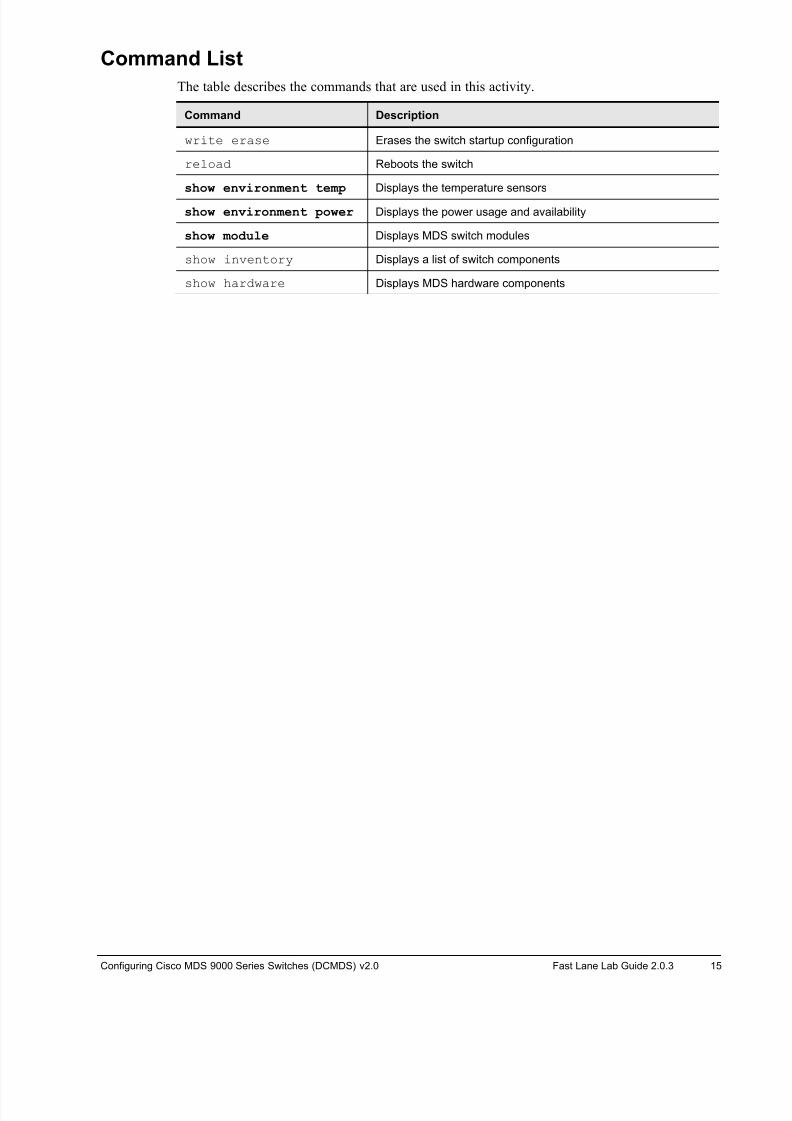
Command List
The table describes the commands that are used in this activity.
Command Description
write erase Erases the switch startup configuration
reload Reboots the switch
show environment temp Displays the temperature sensors
show environment power Displays the power usage and availability
show module Displays MDS switch modules
show inventory Displays a list of switch components
show hardware Displays MDS hardware components
8/18/2019 FL_DCMDS_2.0.3_LG(1).pdf
http://slidepdf.com/reader/full/fldcmds203lg1pdf 16/482
16 Configuring Cisco MDS 9000 Series Switches (DCMDS) v2.0 © 2014 Fast Lane and Cisco Systems, Inc.
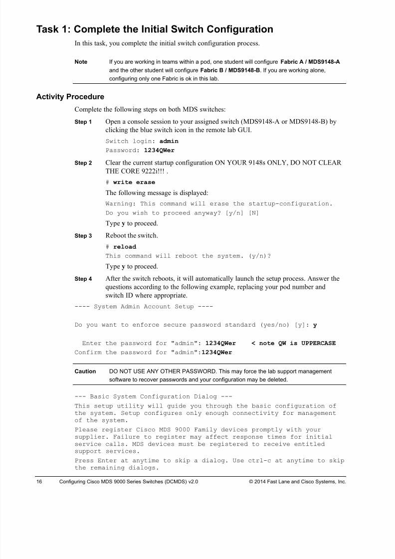
Task 1: Complete the Initial Switch Configuration
In this task, you complete the initial switch configuration process.
Note If you are working in teams within a pod, one student will configure Fabric A / MDS9148-A
and the other student will configure Fabric B / MDS9148-B. If you are working alone,
configuring only one Fabric is ok in this lab.
Activity ProcedureComplete the following steps on both MDS switches:
Step 1 Open a console session to your assigned switch (MDS9148-A or MDS9148-B) by
clicking the blue switch icon in the remote lab GUI.
Switch login: admin
Password: 1234QWer
Step 2 Clear the current startup configuration ON YOUR 9148s ONLY, DO NOT CLEAR
THE CORE 9222i!!! .
# write erase
The following message is displayed:Warning: This command will erase the startup-configuration.
Do you wish to proceed anyway? [y/n] [N]
Type y to proceed.
Step 3 Reboot the switch.
# reload
This command will reboot the system. (y/n)?
Type y to proceed.
Step 4 After the switch reboots, it will automatically launch the setup process. Answer the
questions according to the following example, replacing your pod number and
switch ID where appropriate.
---- System Admin Account Setup ----
Do you want to enforce secure password standard (yes/no) [y]: y
Enter the password for "admin": 1234QWer < note QW is UPPERCASE
Confirm the password for "admin":1234QWer
Caution DO NOT USE ANY OTHER PASSWORD. This may force the lab support management
software to recover passwords and your configuration may be deleted.
--- Basic System Configuration Dialog ---
This setup utility will guide you through the basic configuration ofthe system. Setup configures only enough connectivity for managementof the system.
Please register Cisco MDS 9000 Family devices promptly with yoursupplier. Failure to register may affect response times for initialservice calls. MDS devices must be registered to receive entitledsupport services.
Press Enter at anytime to skip a dialog. Use ctrl-c at anytime to skipthe remaining dialogs.
8/18/2019 FL_DCMDS_2.0.3_LG(1).pdf
http://slidepdf.com/reader/full/fldcmds203lg1pdf 17/482
Configuring Cisco MDS 9000 Series Switches (DCMDS) v2.0 Fast Lane Lab Guide 2.0.3 17
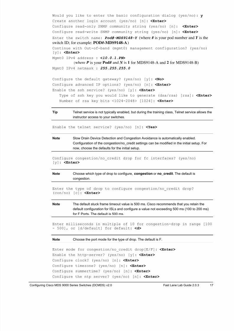
Would you like to enter the basic configuration dialog (yes/no): y
Create another login account (yes/no) [n]: <Enter>
Configure read-only SNMP community string (yes/no) [n]: <Enter>
Configure read-write SNMP community string (yes/no) [n]: <Enter>
Enter the switch name: Pod#-MDS9148-Y (where # is your pod number and Y is the
switch ID; for example: POD#-MDS9148-A)
Continue with Out-of-band (mgmt0) management configuration? (yes/no)[y]: <Enter>
Mgmt0 IPv4 address : <10.0.1.PN > (where P is your Pod# and N is 1 for MDS9148-A and 2 for MDS9148-B)
Mgmt0 IPv4 netmask : 255.255.255.0
Configure the default gateway? (yes/no) [y]: <No>
Configure advanced IP options? (yes/no) [n]: <Enter>
Enable the ssh service? (yes/no) [y]: <Enter>
Type of ssh key you would like to generate (dsa/rsa) [rsa]: <Enter>
Number of rsa key bits <1024-2048> [1024]: <Enter>
Tip Telnet service is not typically enabled, but during the training class, Telnet service allows the
instructor access to your switches.
Enable the telnet service? (yes/no) [n]: <Yes>
Note Slow Drain Device Detection and Congestion Avoidance is automatically enabled.
Configuration of the congestion/no_credit settings can be modified in the initial setup. For
now, choose the defaults for the initial setup.
Configure congestion/no_credit drop for fc interfaces? (yes/no)[y]: <Enter>
Note Choose which type of drop to configure, congestion or no_credit. The default iscongestion.
Enter the type of drop to configure congestion/no_credit drop?(con/no) [c]: <Enter>
Note The default stuck frame timeout value is 500 ms. Cisco recommends that you retain the
default configuration for ISLs and configure a value not exceeding 500 ms (100 to 200 ms)
for F Ports. The default is 500 ms.
Enter milliseconds in multiple of 10 for congestion-drop in range [100- 500], or [d/default] for default: <d>
Note Choose the port mode for the type of drop. The default is F.
Enter mode for congestion/no_credit drop[E/F]: <Enter>
Enable the http-server? (yes/no) [y]: <Enter>
Configure clock? (yes/no) [n]: <Enter>
Configure timezone? (yes/no) [n]: <Enter>
Configure summertime? (yes/no) [n]: <Enter>
Configure the ntp server? (yes/no) [n]: <Enter>
8/18/2019 FL_DCMDS_2.0.3_LG(1).pdf
http://slidepdf.com/reader/full/fldcmds203lg1pdf 18/482
18 Configuring Cisco MDS 9000 Series Switches (DCMDS) v2.0 © 2014 Fast Lane and Cisco Systems, Inc.
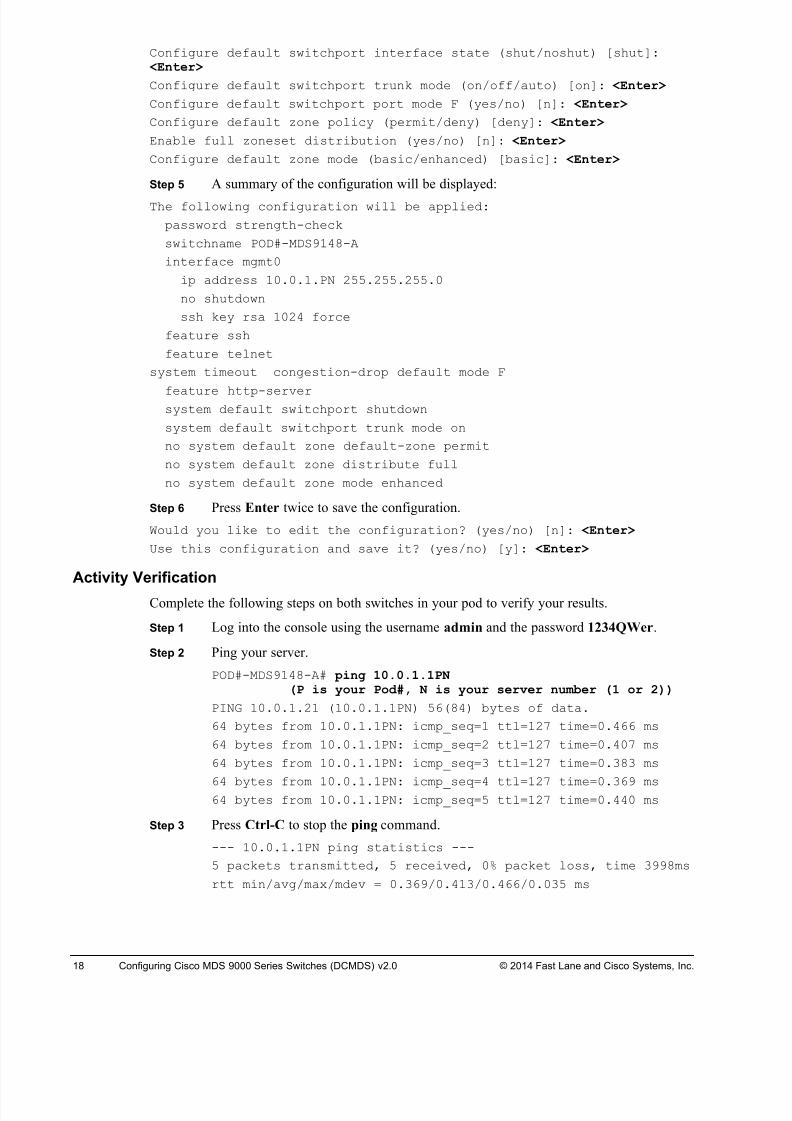
Configure default switchport interface state (shut/noshut) [shut]: <Enter>
Configure default switchport trunk mode (on/off/auto) [on]: <Enter>
Configure default switchport port mode F (yes/no) [n]: <Enter>
Configure default zone policy (permit/deny) [deny]: <Enter>
Enable full zoneset distribution (yes/no) [n]: <Enter>
Configure default zone mode (basic/enhanced) [basic]: <Enter>
Step 5 A summary of the configuration will be displayed:
The following configuration will be applied:
password strength-check
switchname POD#-MDS9148-A
interface mgmt0
ip address 10.0.1.PN 255.255.255.0
no shutdown
ssh key rsa 1024 force
feature ssh
feature telnet
system timeout congestion-drop default mode F
feature http-serversystem default switchport shutdown
system default switchport trunk mode on
no system default zone default-zone permit
no system default zone distribute full
no system default zone mode enhanced
Step 6 Press Enter twice to save the configuration.
Would you like to edit the configuration? (yes/no) [n]: <Enter>
Use this configuration and save it? (yes/no) [y]: <Enter>
Activity Verification
Complete the following steps on both switches in your pod to verify your results.
Step 1 Log into the console using the username admin and the password 1234QWer.
Step 2 Ping your server.
POD#-MDS9148-A# ping 10.0.1.1PN(P is your Pod#, N is your server number (1 or 2))
PING 10.0.1.21 (10.0.1.1PN) 56(84) bytes of data.
64 bytes from 10.0.1.1PN: icmp_seq=1 ttl=127 time=0.466 ms
64 bytes from 10.0.1.1PN: icmp_seq=2 ttl=127 time=0.407 ms
64 bytes from 10.0.1.1PN: icmp_seq=3 ttl=127 time=0.383 ms
64 bytes from 10.0.1.1PN: icmp_seq=4 ttl=127 time=0.369 ms64 bytes from 10.0.1.1PN: icmp_seq=5 ttl=127 time=0.440 ms
Step 3 Press Ctrl-C to stop the ping command.
--- 10.0.1.1PN ping statistics ---
5 packets transmitted, 5 received, 0% packet loss, time 3998ms
rtt min/avg/max/mdev = 0.369/0.413/0.466/0.035 ms
8/18/2019 FL_DCMDS_2.0.3_LG(1).pdf
http://slidepdf.com/reader/full/fldcmds203lg1pdf 19/482
Configuring Cisco MDS 9000 Series Switches (DCMDS) v2.0 Fast Lane Lab Guide 2.0.3 19
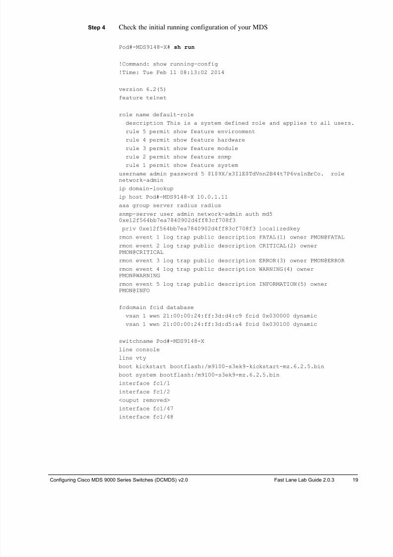
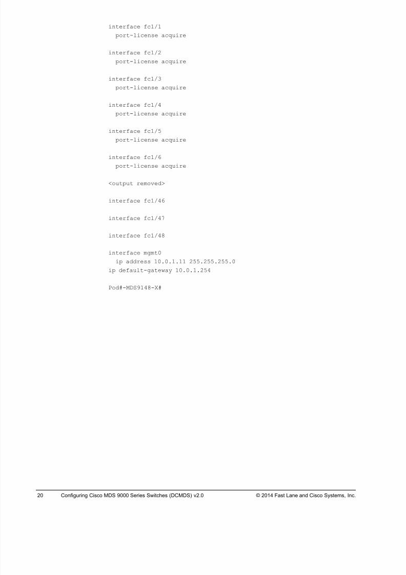
Step 4 Check the initial running configuration of your MDS
Pod#-MDS9148-X# sh run
!Command: show running-config
!Time: Tue Feb 11 08:13:02 2014
version 6.2(5)
feature telnet
role name default-role
description This is a system defined role and applies to all users.
rule 5 permit show feature environment
rule 4 permit show feature hardware
rule 3 permit show feature module
rule 2 permit show feature snmp
rule 1 permit show feature system
username admin password 5 $1$9X/x3IlE$TdVnn2B44t7P6vslnBrCo. rolenetwork-admin
ip domain-lookup
ip host Pod#-MDS9148-X 10.0.1.11
aaa group server radius radius
snmp-server user admin network-admin auth md50xe12f564bb7ea7840902d4ff83cf708f3
priv 0xe12f564bb7ea7840902d4ff83cf708f3 localizedkey
rmon event 1 log trap public description FATAL(1) owner PMON@FATAL
rmon event 2 log trap public description CRITICAL(2) ownerPMON@CRITICAL
rmon event 3 log trap public description ERROR(3) owner PMON@ERROR
rmon event 4 log trap public description WARNING(4) ownerPMON@WARNING
rmon event 5 log trap public description INFORMATION(5) owner
PMON@INFO
fcdomain fcid database
vsan 1 wwn 21:00:00:24:ff:3d:d4:c9 fcid 0x030000 dynamic
vsan 1 wwn 21:00:00:24:ff:3d:d5:a4 fcid 0x030100 dynamic
switchname Pod#-MDS9148-X
line console
line vty
boot kickstart bootflash:/m9100-s3ek9-kickstart-mz.6.2.5.bin
boot system bootflash:/m9100-s3ek9-mz.6.2.5.bin
interface fc1/1
interface fc1/2
<ouput removed>
interface fc1/47
interface fc1/48
8/18/2019 FL_DCMDS_2.0.3_LG(1).pdf
http://slidepdf.com/reader/full/fldcmds203lg1pdf 20/482
20 Configuring Cisco MDS 9000 Series Switches (DCMDS) v2.0 © 2014 Fast Lane and Cisco Systems, Inc.
interface fc1/1
port-license acquire
interface fc1/2
port-license acquire
interface fc1/3
port-license acquire
interface fc1/4
port-license acquire
interface fc1/5
port-license acquire
interface fc1/6
port-license acquire
<output removed>
interface fc1/46
interface fc1/47
interface fc1/48
interface mgmt0
ip address 10.0.1.11 255.255.255.0
ip default-gateway 10.0.1.254
Pod#-MDS9148-X#
8/18/2019 FL_DCMDS_2.0.3_LG(1).pdf
http://slidepdf.com/reader/full/fldcmds203lg1pdf 21/482
Configuring Cisco MDS 9000 Series Switches (DCMDS) v2.0 Fast Lane Lab Guide 2.0.3 21
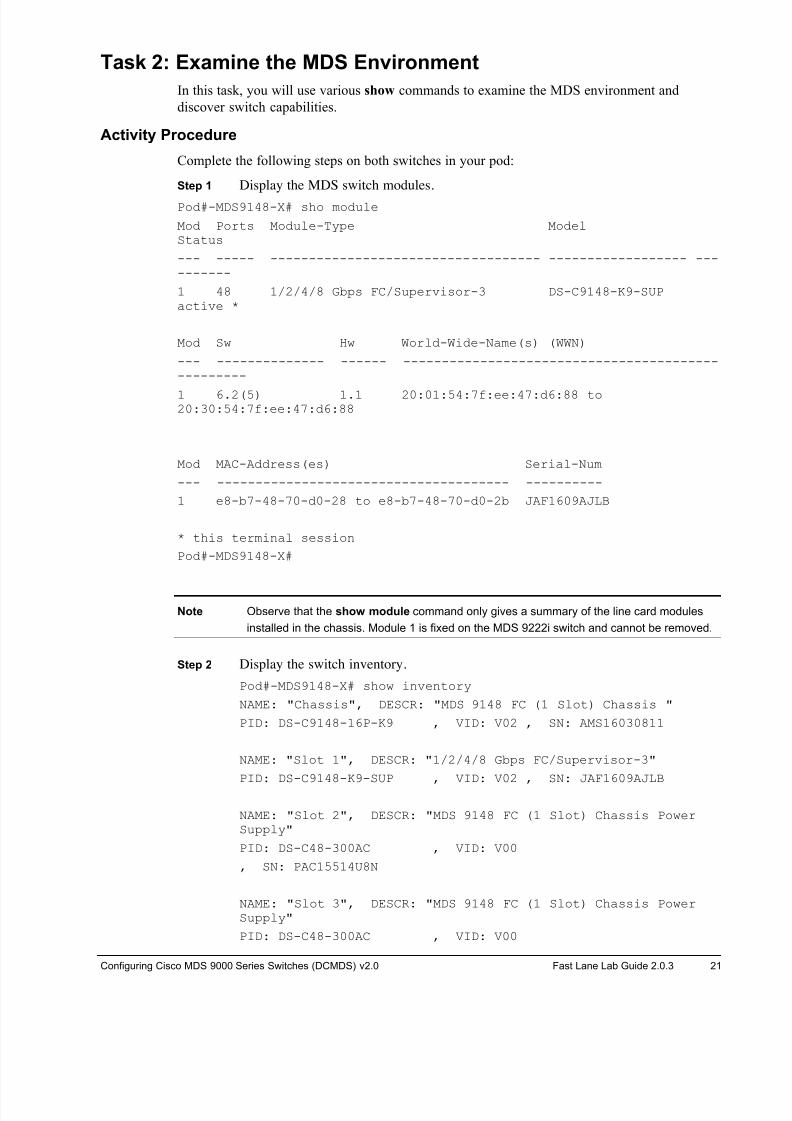
Task 2: Examine the MDS Environment
In this task, you will use various show commands to examine the MDS environment and
discover switch capabilities.
Activity Procedure
Complete the following steps on both switches in your pod:
Step 1 Display the MDS switch modules.
Pod#-MDS9148-X# sho module
Mod Ports Module-Type ModelStatus
--- ----- ----------------------------------- ------------------ ----------
1 48 1/2/4/8 Gbps FC/Supervisor-3 DS-C9148-K9-SUPactive *
Mod Sw Hw World-Wide-Name(s) (WWN)
--- -------------- ------ --------------------------------------------------
1 6.2(5) 1.1 20:01:54:7f:ee:47:d6:88 to20:30:54:7f:ee:47:d6:88
Mod MAC-Address(es) Serial-Num
--- -------------------------------------- ----------
1 e8-b7-48-70-d0-28 to e8-b7-48-70-d0-2b JAF1609AJLB
* this terminal session
Pod#-MDS9148-X#
Note Observe that the show module command only gives a summary of the line card modules
installed in the chassis. Module 1 is fixed on the MDS 9222i switch and cannot be removed.
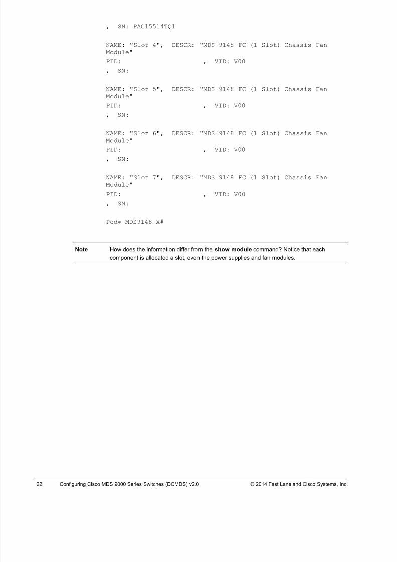
Step 2 Display the switch inventory.
Pod#-MDS9148-X# show inventory
NAME: "Chassis", DESCR: "MDS 9148 FC (1 Slot) Chassis "
PID: DS-C9148-16P-K9 , VID: V02 , SN: AMS16030811
NAME: "Slot 1", DESCR: "1/2/4/8 Gbps FC/Supervisor-3"
PID: DS-C9148-K9-SUP , VID: V02 , SN: JAF1609AJLB
NAME: "Slot 2", DESCR: "MDS 9148 FC (1 Slot) Chassis PowerSupply"
PID: DS-C48-300AC , VID: V00
, SN: PAC15514U8N
NAME: "Slot 3", DESCR: "MDS 9148 FC (1 Slot) Chassis PowerSupply"
PID: DS-C48-300AC , VID: V00
8/18/2019 FL_DCMDS_2.0.3_LG(1).pdf
http://slidepdf.com/reader/full/fldcmds203lg1pdf 22/482
22 Configuring Cisco MDS 9000 Series Switches (DCMDS) v2.0 © 2014 Fast Lane and Cisco Systems, Inc.
, SN: PAC15514TQ1
NAME: "Slot 4", DESCR: "MDS 9148 FC (1 Slot) Chassis FanModule"
PID: , VID: V00
, SN:
NAME: "Slot 5", DESCR: "MDS 9148 FC (1 Slot) Chassis Fan
Module"PID: , VID: V00
, SN:
NAME: "Slot 6", DESCR: "MDS 9148 FC (1 Slot) Chassis FanModule"
PID: , VID: V00
, SN:
NAME: "Slot 7", DESCR: "MDS 9148 FC (1 Slot) Chassis FanModule"
PID: , VID: V00, SN:
Pod#-MDS9148-X#
Note How does the information differ from the show module command? Notice that each
component is allocated a slot, even the power supplies and fan modules.
8/18/2019 FL_DCMDS_2.0.3_LG(1).pdf
http://slidepdf.com/reader/full/fldcmds203lg1pdf 23/482
Configuring Cisco MDS 9000 Series Switches (DCMDS) v2.0 Fast Lane Lab Guide 2.0.3 23
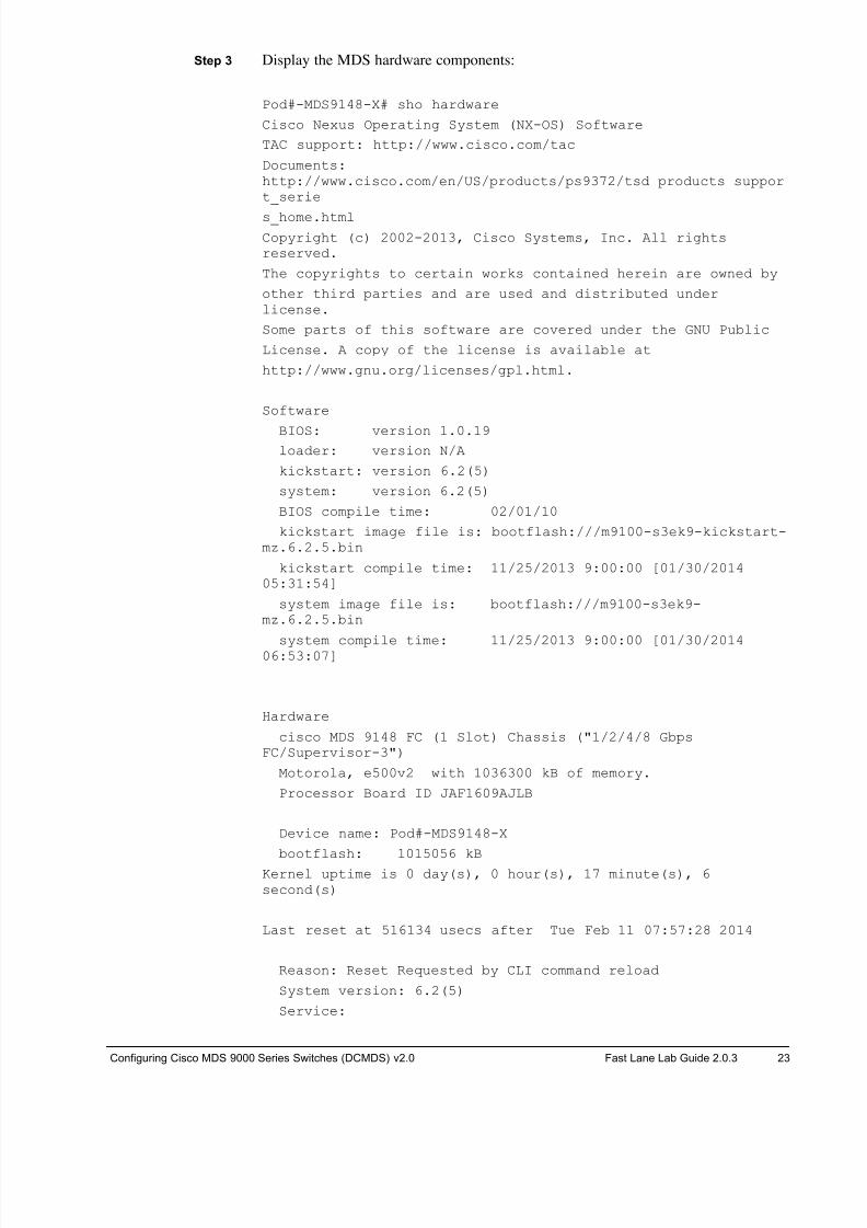
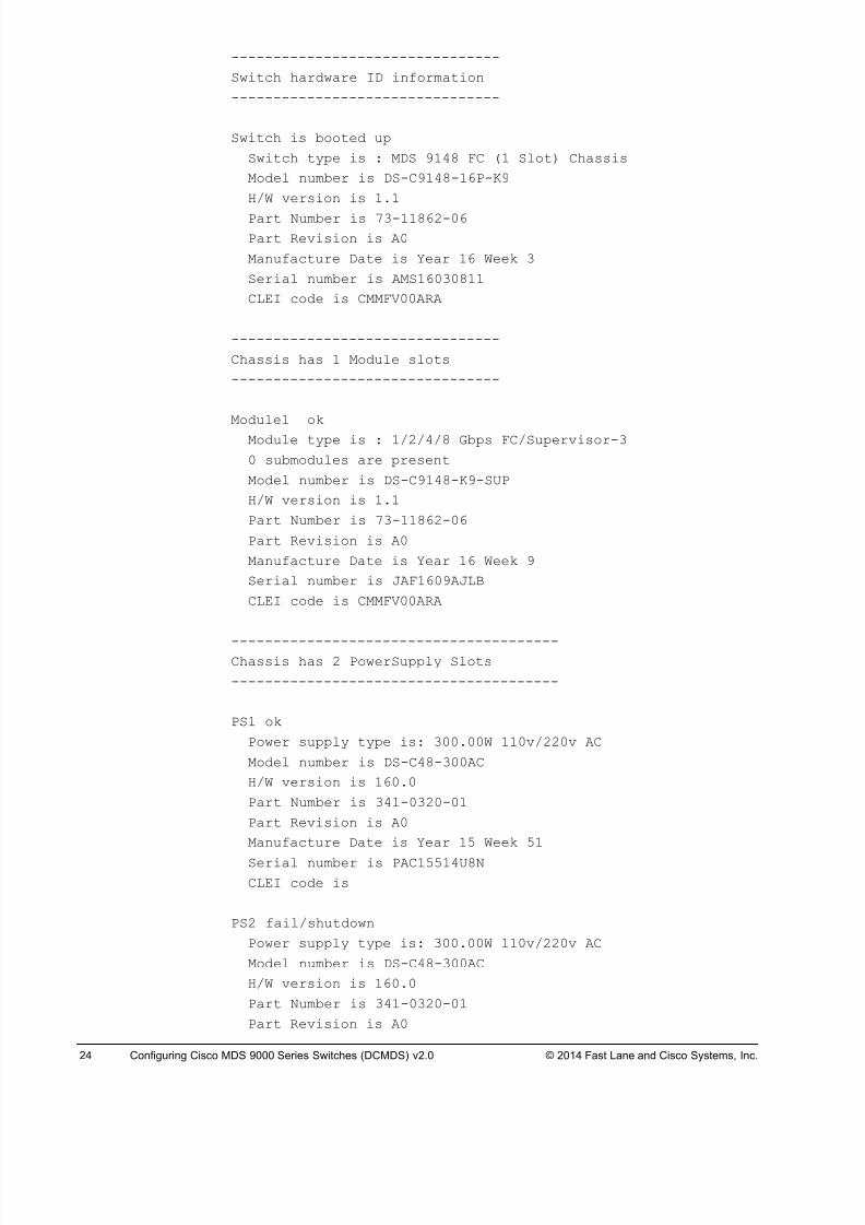
Step 3 Display the MDS hardware components:
Pod#-MDS9148-X# sho hardware
Cisco Nexus Operating System (NX-OS) Software
TAC support: http://www.cisco.com/tac
Documents:http://www.cisco.com/en/US/products/ps9372/tsd_products_support_serie
s_home.html
Copyright (c) 2002-2013, Cisco Systems, Inc. All rightsreserved.
The copyrights to certain works contained herein are owned by
other third parties and are used and distributed underlicense.
Some parts of this software are covered under the GNU Public
License. A copy of the license is available at
http://www.gnu.org/licenses/gpl.html.
Software
BIOS: version 1.0.19loader: version N/A
kickstart: version 6.2(5)
system: version 6.2(5)
BIOS compile time: 02/01/10
kickstart image file is: bootflash:///m9100-s3ek9-kickstart-mz.6.2.5.bin
kickstart compile time: 11/25/2013 9:00:00 [01/30/201405:31:54]
system image file is: bootflash:///m9100-s3ek9-mz.6.2.5.bin
system compile time: 11/25/2013 9:00:00 [01/30/201406:53:07]
Hardware
cisco MDS 9148 FC (1 Slot) Chassis ("1/2/4/8 GbpsFC/Supervisor-3")
Motorola, e500v2 with 1036300 kB of memory.
Processor Board ID JAF1609AJLB
Device name: Pod#-MDS9148-X
bootflash: 1015056 kBKernel uptime is 0 day(s), 0 hour(s), 17 minute(s), 6second(s)
Last reset at 516134 usecs after Tue Feb 11 07:57:28 2014
Reason: Reset Requested by CLI command reload
System version: 6.2(5)
Service:
8/18/2019 FL_DCMDS_2.0.3_LG(1).pdf
http://slidepdf.com/reader/full/fldcmds203lg1pdf 24/482
24 Configuring Cisco MDS 9000 Series Switches (DCMDS) v2.0 © 2014 Fast Lane and Cisco Systems, Inc.
--------------------------------
Switch hardware ID information
--------------------------------
Switch is booted up
Switch type is : MDS 9148 FC (1 Slot) Chassis
Model number is DS-C9148-16P-K9
H/W version is 1.1
Part Number is 73-11862-06
Part Revision is A0
Manufacture Date is Year 16 Week 3
Serial number is AMS16030811
CLEI code is CMMFV00ARA
--------------------------------
Chassis has 1 Module slots
--------------------------------
Module1 ok
Module type is : 1/2/4/8 Gbps FC/Supervisor-3
0 submodules are present
Model number is DS-C9148-K9-SUP
H/W version is 1.1
Part Number is 73-11862-06
Part Revision is A0
Manufacture Date is Year 16 Week 9
Serial number is JAF1609AJLB
CLEI code is CMMFV00ARA
---------------------------------------Chassis has 2 PowerSupply Slots
---------------------------------------
PS1 ok
Power supply type is: 300.00W 110v/220v AC
Model number is DS-C48-300AC
H/W version is 160.0
Part Number is 341-0320-01
Part Revision is A0
Manufacture Date is Year 15 Week 51
Serial number is PAC15514U8N
CLEI code is
PS2 fail/shutdown
Power supply type is: 300.00W 110v/220v AC
Model number is DS-C48-300AC
H/W version is 160.0
Part Number is 341-0320-01
Part Revision is A0
8/18/2019 FL_DCMDS_2.0.3_LG(1).pdf
http://slidepdf.com/reader/full/fldcmds203lg1pdf 25/482
Configuring Cisco MDS 9000 Series Switches (DCMDS) v2.0 Fast Lane Lab Guide 2.0.3 25
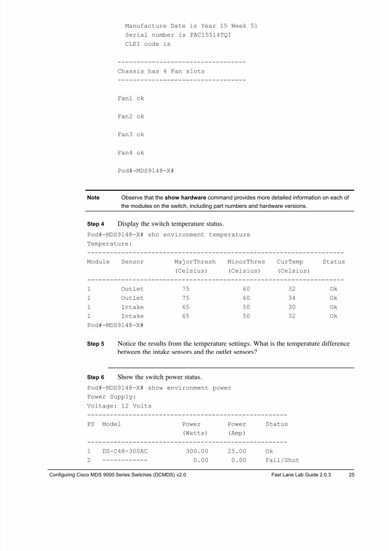
Manufacture Date is Year 15 Week 51
Serial number is PAC15514TQ1
CLEI code is
----------------------------------
Chassis has 4 Fan slots
----------------------------------
Fan1 ok
Fan2 ok
Fan3 ok
Fan4 ok
Pod#-MDS9148-X#
Note Observe that the show hardware command provides more detailed information on each of
the modules on the switch, including part numbers and hardware versions.
Step 4 Display the switch temperature status.
Pod#-MDS9148-X# sho environment temperature
Temperature:
--------------------------------------------------------------------
Module Sensor MajorThresh MinorThres CurTemp Status
(Celsius) (Celsius) (Celsius)
--------------------------------------------------------------------
1 Outlet 75 60 32 Ok1 Outlet 75 60 34 Ok
1 Intake 65 50 30 Ok
1 Intake 65 50 32 Ok
Pod#-MDS9148-X#
Step 5 Notice the results from the temperature settings. What is the temperature difference
between the intake sensors and the outlet sensors?
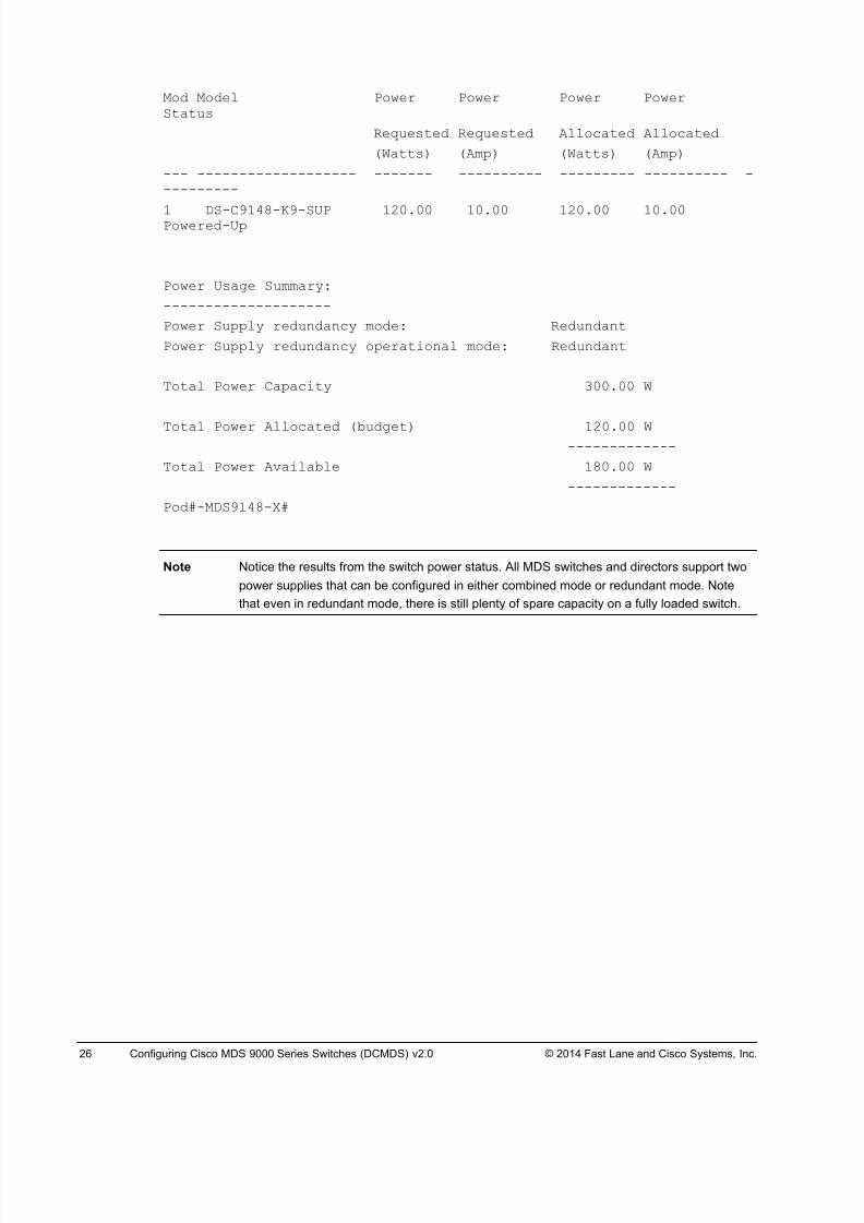
Step 6 Show the switch power status.
Pod#-MDS9148-X# show environment power
Power Supply:
Voltage: 12 Volts
-----------------------------------------------------
PS Model Power Power Status
(Watts) (Amp)
-----------------------------------------------------
1 DS-C48-300AC 300.00 25.00 Ok
2 ------------ 0.00 0.00 Fail/Shut
8/18/2019 FL_DCMDS_2.0.3_LG(1).pdf
http://slidepdf.com/reader/full/fldcmds203lg1pdf 26/482
26 Configuring Cisco MDS 9000 Series Switches (DCMDS) v2.0 © 2014 Fast Lane and Cisco Systems, Inc.
Mod Model Power Power Power PowerStatus
Requested Requested Allocated Allocated
(Watts) (Amp) (Watts) (Amp)
--- ------------------- ------- ---------- --------- ---------- ----------
1 DS-C9148-K9-SUP 120.00 10.00 120.00 10.00Powered-Up
Power Usage Summary:
--------------------
Power Supply redundancy mode: Redundant
Power Supply redundancy operational mode: Redundant
Total Power Capacity 300.00 W
Total Power Allocated (budget) 120.00 W-------------
Total Power Available 180.00 W
-------------
Pod#-MDS9148-X#
Note Notice the results from the switch power status. All MDS switches and directors support two
power supplies that can be configured in either combined mode or redundant mode. Note
that even in redundant mode, there is still plenty of spare capacity on a fully loaded switch.
8/18/2019 FL_DCMDS_2.0.3_LG(1).pdf
http://slidepdf.com/reader/full/fldcmds203lg1pdf 27/482
Configuring Cisco MDS 9000 Series Switches (DCMDS) v2.0 Fast Lane Lab Guide 2.0.3 27
Lab 2-2: Upgrading Switch Software Complete this lab activity to practice what you learned in the related lesson.
Activity Objective
In this activity, you will upgrade the NX-OS software and verify that the upgrade was
successful. After completing this activity, you will be able to meet these objectives:
! Troubleshoot incompatible software versions
! Recover a hung switch from the loader prompt
! Upgrade the switch software
Required Resources
These are the resources and equipment required to complete this activity:
! 4 MDS 9000 Series Fibre Channel switches
! Two Windows Server Hosts
! Access to a TFTP server and/or NX-OS images for your platform.
8/18/2019 FL_DCMDS_2.0.3_LG(1).pdf
http://slidepdf.com/reader/full/fldcmds203lg1pdf 28/482
28 Configuring Cisco MDS 9000 Series Switches (DCMDS) v2.0 © 2014 Fast Lane and Cisco Systems, Inc.
Command List
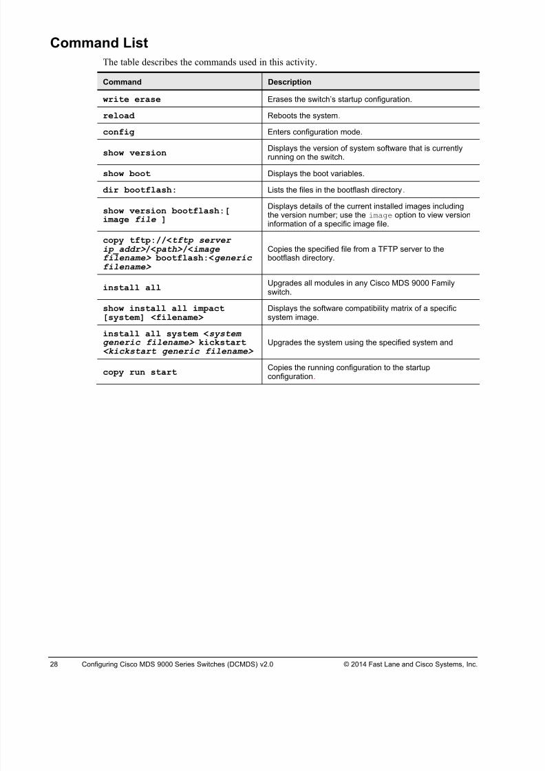
The table describes the commands used in this activity.
Command Description
write erase Erases the switch’s startup configuration.
reload Reboots the system.
config Enters configuration mode.
show versionDisplays the version of system software that is currentlyrunning on the switch.
show boot Displays the boot variables.
dir bootflash: Lists the files in the bootflash directory.
show version bootflash:[image file ]
Displays details of the current installed images includingthe version number; use the image option to view versioninformation of a specific image file.
copy tftp://<tftp serverip_addr> /< path> /<imagefilename> bootflash:<generic
filename>
Copies the specified file from a TFTP server to thebootflash directory.
install allUpgrades all modules in any Cisco MDS 9000 Familyswitch.
show install all impact[system] <filename>
Displays the software compatibility matrix of a specificsystem image.
install all system <systemgeneric filename> kickstart<kickstart generic filename>
Upgrades the system using the specified system and
copy run startCopies the running configuration to the startupconfiguration.
8/18/2019 FL_DCMDS_2.0.3_LG(1).pdf
http://slidepdf.com/reader/full/fldcmds203lg1pdf 29/482
Configuring Cisco MDS 9000 Series Switches (DCMDS) v2.0 Fast Lane Lab Guide 2.0.3 29
Task 1: Tr oubleshoot Software Version Conflicts
In this task, you complete the initial switch configuration process.
Note If you are working in teams within a pod, one student will configure MDS9148-A and the
other student will configure MDS9148-B. If you are working alone, you will need to configure
one of the switches (there is no need to do both). Later exercises will require both students
sharing a pod to work together.
Activity Procedure
Complete the following steps on both MDS switches:
Step 1 If not still open from the last lab, open a console session to your assigned switch
(MDS9148-A or MDS9148-B) by clicking the blue switch icon in the remote lab
GUI.
Note If the switch ask for username and password at this step log in with user “admin” and
password “1234QWer”.
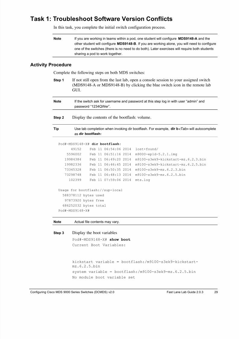
Step 2 Display the contents of the bootflash: volume.
Tip Use tab completion when invoking dir bootflash. For example, dir b<Tab> will autocomplete
as dir bootflash:
Pod#-MDS9148-X# dir bootflash:
49152 Feb 11 06:54:06 2014 lost+found/
5596002 Feb 11 06:51:16 2014 m9000-epld-5.2.1.img
19984384 Feb 11 06:49:20 2014 m9100-s3ek9-kickstart-mz.6.2.3.bin
19982336 Feb 11 06:46:45 2014 m9100-s3ek9-kickstart-mz.6.2.5.bin
73345328 Feb 11 06:50:35 2014 m9100-s3ek9-mz.6.2.3.bin
73298748 Feb 11 06:48:13 2014 m9100-s3ek9-mz.6.2.5.bin
102399 Feb 11 07:59:06 2014 mts.log
Usage for bootflash://sup-local
588378112 bytes used
97873920 bytes free
686252032 bytes total
Pod#-MDS9148-X#
Note Actual file contents may vary.
Step 3 Display the boot variables
Pod#-MDS9148-X# show boot
Current Boot Variables:
kickstart variable = bootflash:/m9100-s3ek9-kickstart-mz.6.2.5.bin
system variable = bootflash:/m9100-s3ek9-mz.6.2.5.bin
No module boot variable set
8/18/2019 FL_DCMDS_2.0.3_LG(1).pdf
http://slidepdf.com/reader/full/fldcmds203lg1pdf 30/482
30 Configuring Cisco MDS 9000 Series Switches (DCMDS) v2.0 © 2014 Fast Lane and Cisco Systems, Inc.
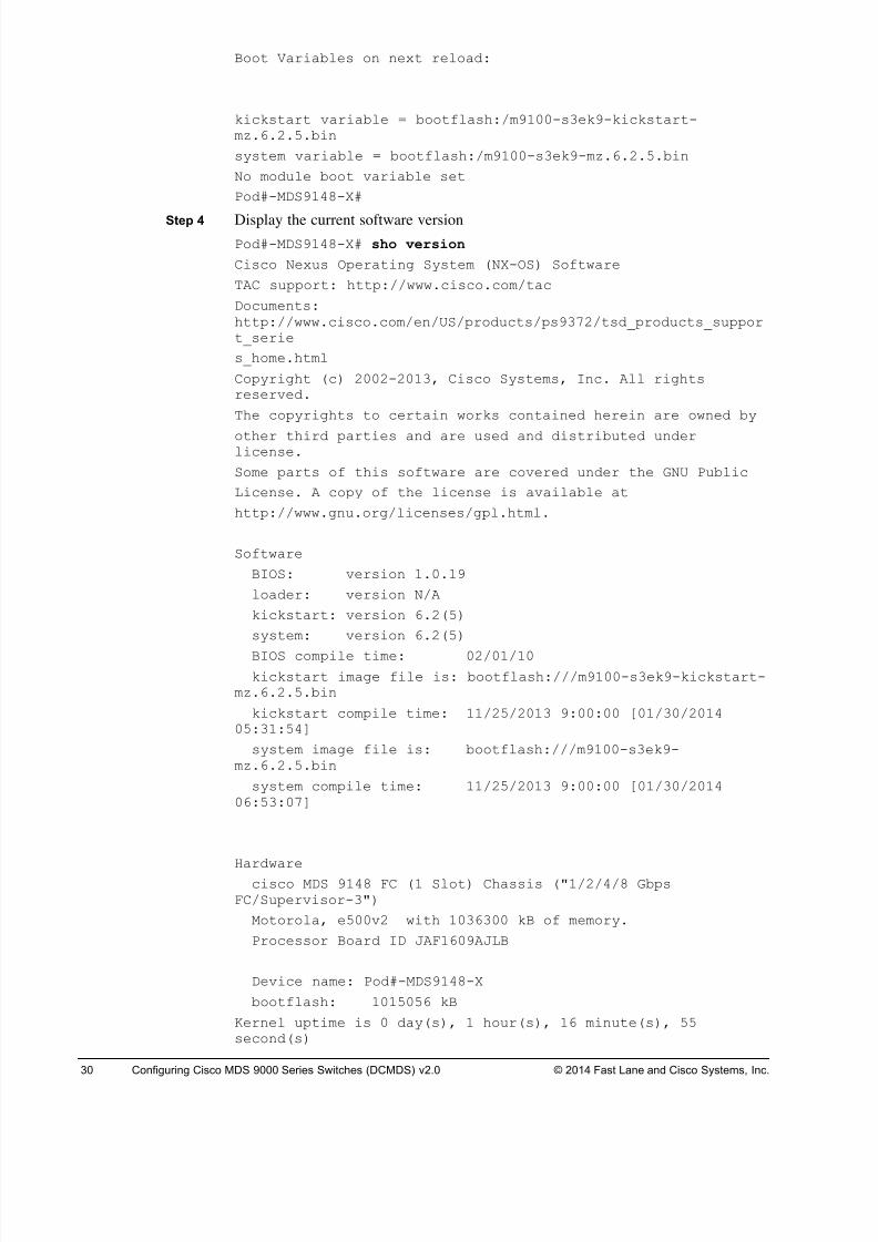
Boot Variables on next reload:
kickstart variable = bootflash:/m9100-s3ek9-kickstart-mz.6.2.5.bin
system variable = bootflash:/m9100-s3ek9-mz.6.2.5.bin
No module boot variable set
Pod#-MDS9148-X#
Step 4 Display the current software version
Pod#-MDS9148-X# sho version
Cisco Nexus Operating System (NX-OS) Software
TAC support: http://www.cisco.com/tac
Documents:http://www.cisco.com/en/US/products/ps9372/tsd_products_support_serie
s_home.html
Copyright (c) 2002-2013, Cisco Systems, Inc. All rightsreserved.
The copyrights to certain works contained herein are owned by
other third parties and are used and distributed underlicense.
Some parts of this software are covered under the GNU Public
License. A copy of the license is available at
http://www.gnu.org/licenses/gpl.html.
Software
BIOS: version 1.0.19
loader: version N/A
kickstart: version 6.2(5)
system: version 6.2(5)
BIOS compile time: 02/01/10
kickstart image file is: bootflash:///m9100-s3ek9-kickstart-mz.6.2.5.bin
kickstart compile time: 11/25/2013 9:00:00 [01/30/201405:31:54]
system image file is: bootflash:///m9100-s3ek9-mz.6.2.5.bin
system compile time: 11/25/2013 9:00:00 [01/30/201406:53:07]
Hardwarecisco MDS 9148 FC (1 Slot) Chassis ("1/2/4/8 Gbps
FC/Supervisor-3")
Motorola, e500v2 with 1036300 kB of memory.
Processor Board ID JAF1609AJLB
Device name: Pod#-MDS9148-X
bootflash: 1015056 kB
Kernel uptime is 0 day(s), 1 hour(s), 16 minute(s), 55second(s)
8/18/2019 FL_DCMDS_2.0.3_LG(1).pdf
http://slidepdf.com/reader/full/fldcmds203lg1pdf 31/482
Configuring Cisco MDS 9000 Series Switches (DCMDS) v2.0 Fast Lane Lab Guide 2.0.3 31
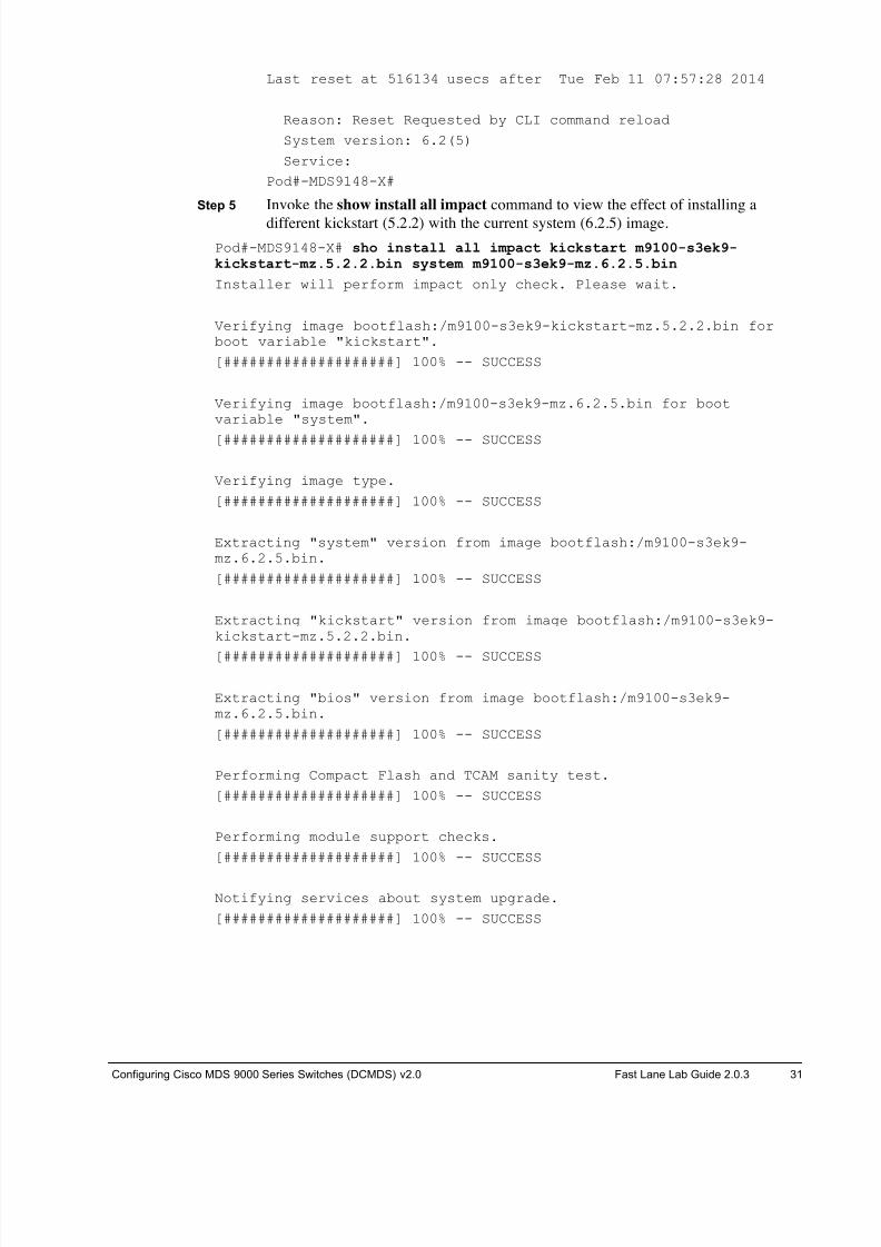
Last reset at 516134 usecs after Tue Feb 11 07:57:28 2014
Reason: Reset Requested by CLI command reload
System version: 6.2(5)
Service:
Pod#-MDS9148-X#
Step 5 Invoke the show install all impact command to view the effect of installing a
different kickstart (5.2.2) with the current system (6.2.5) image.
Pod#-MDS9148-X# sho install all impact kickstart m9100-s3ek9-kickstart-mz.5.2.2.bin system m9100-s3ek9-mz.6.2.5.bin
Installer will perform impact only check. Please wait.
Verifying image bootflash:/m9100-s3ek9-kickstart-mz.5.2.2.bin forboot variable "kickstart".
[####################] 100% -- SUCCESS
Verifying image bootflash:/m9100-s3ek9-mz.6.2.5.bin for bootvariable "system".
[####################] 100% -- SUCCESS
Verifying image type.
[####################] 100% -- SUCCESS
Extracting "system" version from image bootflash:/m9100-s3ek9-mz.6.2.5.bin.
[####################] 100% -- SUCCESS
Extracting "kickstart" version from image bootflash:/m9100-s3ek9-kickstart-mz.5.2.2.bin.
[####################] 100% -- SUCCESS
Extracting "bios" version from image bootflash:/m9100-s3ek9-mz.6.2.5.bin.
[####################] 100% -- SUCCESS
Performing Compact Flash and TCAM sanity test.
[####################] 100% -- SUCCESS
Performing module support checks.
[####################] 100% -- SUCCESS
Notifying services about system upgrade.
[####################] 100% -- SUCCESS
8/18/2019 FL_DCMDS_2.0.3_LG(1).pdf
http://slidepdf.com/reader/full/fldcmds203lg1pdf 32/482
32 Configuring Cisco MDS 9000 Series Switches (DCMDS) v2.0 © 2014 Fast Lane and Cisco Systems, Inc.
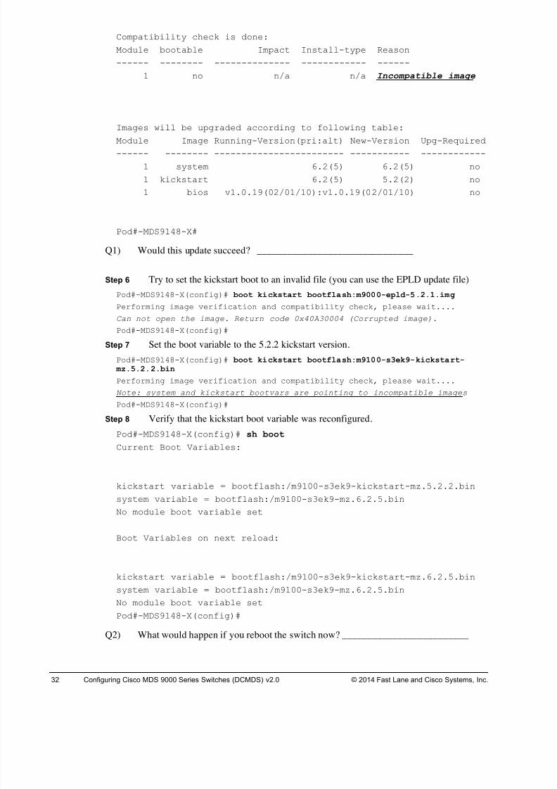
Compatibility check is done:
Module bootable Impact Install-type Reason
------ -------- -------------- ------------ ------
1 no n/a n/a Incompatible image
Images will be upgraded according to following table:
Module Image Running-Version(pri:alt) New-Version Upg-Required
------ -------- ------------------------ ----------- ------------
1 system 6.2(5) 6.2(5) no
1 kickstart 6.2(5) 5.2(2) no
1 bios v1.0.19(02/01/10):v1.0.19(02/01/10) no
Pod#-MDS9148-X#
Q1) Would this update succeed? _______________________________
Step 6 Try to set the kickstart boot to an invalid file (you can use the EPLD update file)
Pod#-MDS9148-X(config)# boot kickstart bootflash:m9000-epld-5.2.1.img
Performing image verification and compatibility check, please wait....
Can not open the image. Return code 0x40A30004 (Corrupted image).
Pod#-MDS9148-X(config)#
Step 7 Set the boot variable to the 5.2.2 kickstart version.
Pod#-MDS9148-X(config)# boot kickstart bootflash:m9100-s3ek9-kickstart- mz.5.2.2.bin
Performing image verification and compatibility check, please wait....
Note: system and kickstart bootvars are pointing to incompatible images
Pod#-MDS9148-X(config)#
Step 8 Verify that the kickstart boot variable was reconfigured.
Pod#-MDS9148-X(config)# sh boot
Current Boot Variables:
kickstart variable = bootflash:/m9100-s3ek9-kickstart-mz.5.2.2.bin
system variable = bootflash:/m9100-s3ek9-mz.6.2.5.bin
No module boot variable set
Boot Variables on next reload:
kickstart variable = bootflash:/m9100-s3ek9-kickstart-mz.6.2.5.bin
system variable = bootflash:/m9100-s3ek9-mz.6.2.5.bin
No module boot variable set
Pod#-MDS9148-X(config)#
Q2) What would happen if you reboot the switch now? _________________________
8/18/2019 FL_DCMDS_2.0.3_LG(1).pdf
http://slidepdf.com/reader/full/fldcmds203lg1pdf 33/482
Configuring Cisco MDS 9000 Series Switches (DCMDS) v2.0 Fast Lane Lab Guide 2.0.3 33
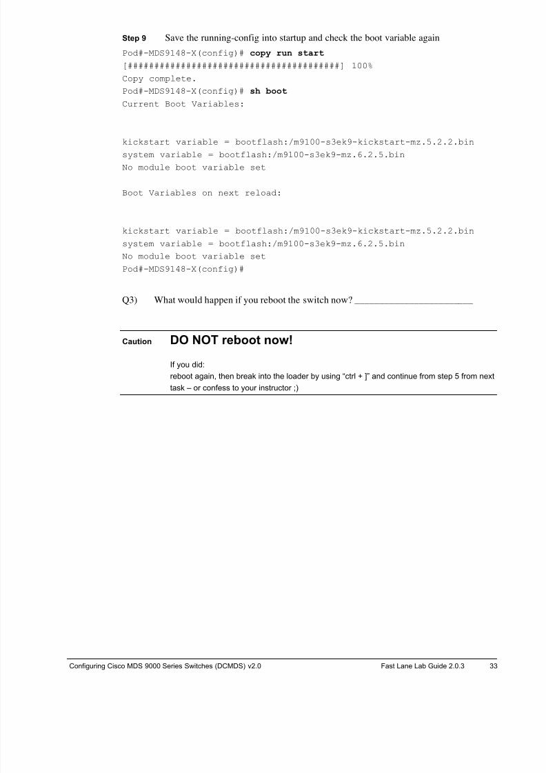
Step 9 Save the running-config into startup and check the boot variable again
Pod#-MDS9148-X(config)# copy run start
[########################################] 100%
Copy complete.
Pod#-MDS9148-X(config)# sh boot
Current Boot Variables:
kickstart variable = bootflash:/m9100-s3ek9-kickstart-mz.5.2.2.bin
system variable = bootflash:/m9100-s3ek9-mz.6.2.5.bin
No module boot variable set
Boot Variables on next reload:
kickstart variable = bootflash:/m9100-s3ek9-kickstart-mz.5.2.2.bin
system variable = bootflash:/m9100-s3ek9-mz.6.2.5.bin
No module boot variable set
Pod#-MDS9148-X(config)#
Q3) What would happen if you reboot the switch now? ________________________
Caution DO NOT reboot now!
If you did:
reboot again, then break into the loader by using “ctrl + ]” and continue from step 5 from next
task – or confess to your instructor ;)
8/18/2019 FL_DCMDS_2.0.3_LG(1).pdf
http://slidepdf.com/reader/full/fldcmds203lg1pdf 34/482
34 Configuring Cisco MDS 9000 Series Switches (DCMDS) v2.0 © 2014 Fast Lane and Cisco Systems, Inc.
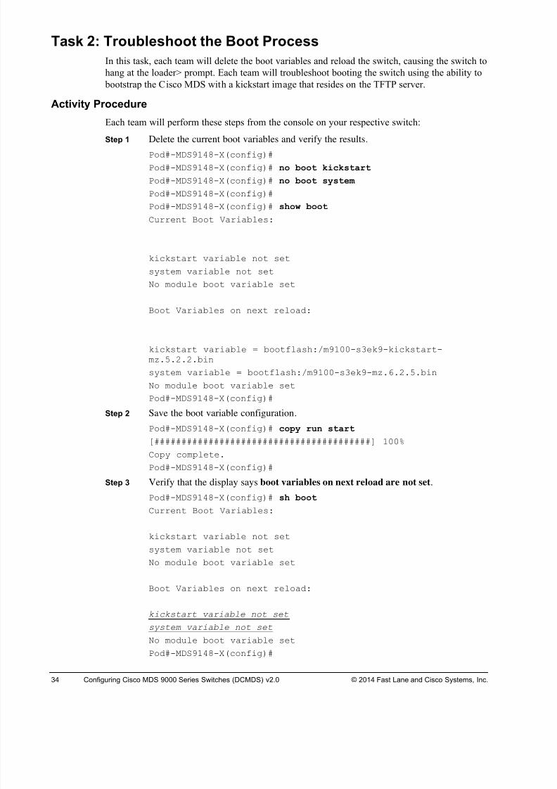
Task 2: Troubleshoot the Boot Process
In this task, each team will delete the boot variables and reload the switch, causing the switch to
hang at the loader> prompt. Each team will troubleshoot booting the switch using the ability to
bootstrap the Cisco MDS with a kickstart image that resides on the TFTP server.
Activity Procedure
Each team will perform these steps from the console on your respective switch:
Step 1 Delete the current boot variables and verify the results.
Pod#-MDS9148-X(config)#
Pod#-MDS9148-X(config)# no boot kickstart
Pod#-MDS9148-X(config)# no boot system
Pod#-MDS9148-X(config)#
Pod#-MDS9148-X(config)# show boot
Current Boot Variables:
kickstart variable not set
system variable not setNo module boot variable set
Boot Variables on next reload:
kickstart variable = bootflash:/m9100-s3ek9-kickstart-mz.5.2.2.bin
system variable = bootflash:/m9100-s3ek9-mz.6.2.5.bin
No module boot variable set
Pod#-MDS9148-X(config)#
Step 2 Save the boot variable configuration.Pod#-MDS9148-X(config)# copy run start
[########################################] 100%
Copy complete.
Pod#-MDS9148-X(config)#
Step 3 Verify that the display says boot variables on next reload are not set.
Pod#-MDS9148-X(config)# sh boot
Current Boot Variables:
kickstart variable not set
system variable not setNo module boot variable set
Boot Variables on next reload:
kickstart variable not set
system variable not set
No module boot variable set
Pod#-MDS9148-X(config)#
8/18/2019 FL_DCMDS_2.0.3_LG(1).pdf
http://slidepdf.com/reader/full/fldcmds203lg1pdf 35/482
Configuring Cisco MDS 9000 Series Switches (DCMDS) v2.0 Fast Lane Lab Guide 2.0.3 35
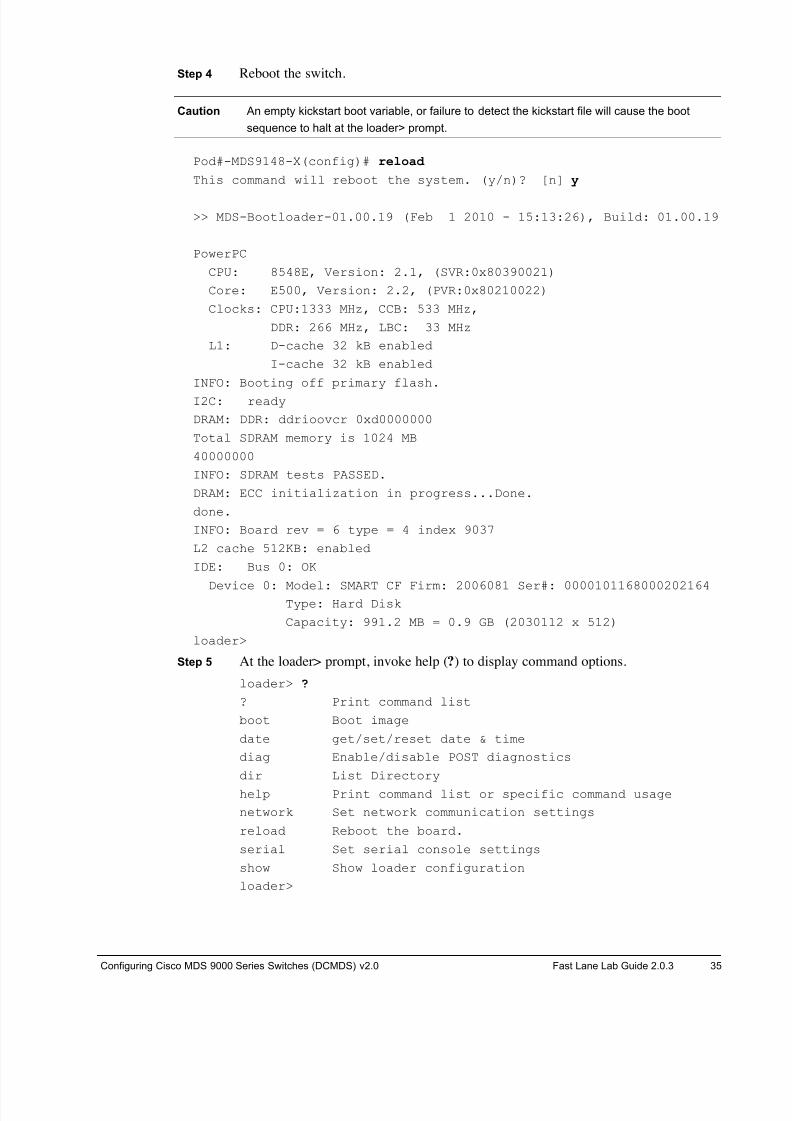
Step 4 Reboot the switch.
Caution An empty kickstart boot variable, or failure to detect the kickstart file will cause the boot
sequence to halt at the loader> prompt.
Pod#-MDS9148-X(config)# reload
This command will reboot the system. (y/n)? [n] y
>> MDS-Bootloader-01.00.19 (Feb 1 2010 - 15:13:26), Build: 01.00.19
PowerPC
CPU: 8548E, Version: 2.1, (SVR:0x80390021)
Core: E500, Version: 2.2, (PVR:0x80210022)
Clocks: CPU:1333 MHz, CCB: 533 MHz,
DDR: 266 MHz, LBC: 33 MHz
L1: D-cache 32 kB enabled
I-cache 32 kB enabled
INFO: Booting off primary flash.
I2C: ready
DRAM: DDR: ddrioovcr 0xd0000000
Total SDRAM memory is 1024 MB
40000000
INFO: SDRAM tests PASSED.
DRAM: ECC initialization in progress...Done.
done.
INFO: Board rev = 6 type = 4 index 9037
L2 cache 512KB: enabled
IDE: Bus 0: OK
Device 0: Model: SMART CF Firm: 2006081 Ser#: 0000101168000202164Type: Hard Disk
Capacity: 991.2 MB = 0.9 GB (2030112 x 512)
loader>
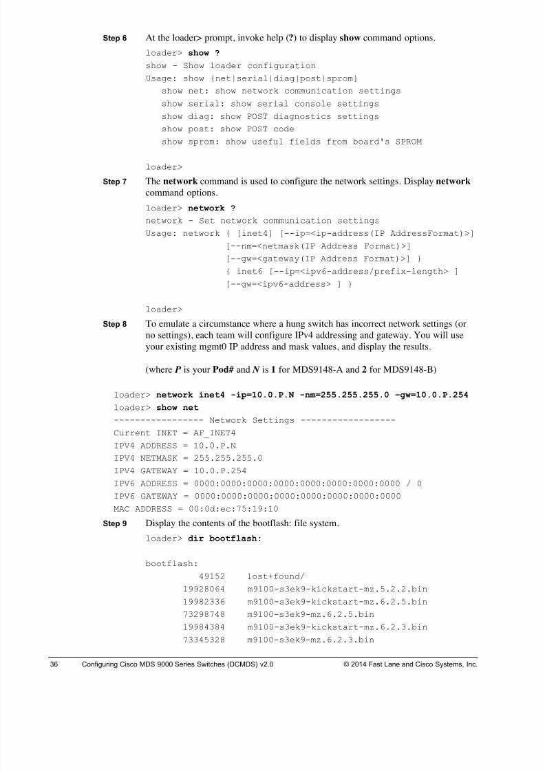
Step 5 At the loader> prompt, invoke help (?) to display command options.
loader> ?
? Print command list
boot Boot image
date get/set/reset date & time
diag Enable/disable POST diagnostics
dir List Directory
help Print command list or specific command usage
network Set network communication settings
reload Reboot the board.
serial Set serial console settings
show Show loader configuration
loader>
8/18/2019 FL_DCMDS_2.0.3_LG(1).pdf
http://slidepdf.com/reader/full/fldcmds203lg1pdf 36/482
36 Configuring Cisco MDS 9000 Series Switches (DCMDS) v2.0 © 2014 Fast Lane and Cisco Systems, Inc.
Step 6 At the loader> prompt, invoke help (?) to display show command options.
loader> show ?
show - Show loader configuration
Usage: show {net|serial|diag|post|sprom}
show net: show network communication settings
show serial: show serial console settings
show diag: show POST diagnostics settings
show post: show POST code
show sprom: show useful fields from board's SPROM
loader>
Step 7 The network command is used to configure the network settings. Display network
command options.
loader> network ?
network - Set network communication settings
Usage: network { [inet4] [--ip=<ip-address(IP AddressFormat)>]
[--nm=<netmask(IP Address Format)>]
[--gw=<gateway(IP Address Format)>] }
{ inet6 [--ip=<ipv6-address/prefix-length> ][--gw=<ipv6-address> ] }
loader>
Step 8 To emulate a circumstance where a hung switch has incorrect network settings (or
no settings), each team will configure IPv4 addressing and gateway. You will use
your existing mgmt0 IP address and mask values, and display the results.
(where P is your Pod# and N is 1 for MDS9148-A and 2 for MDS9148-B)
loader> network inet4 -ip=10.0.P.N -nm=255.255.255.0 –gw=10.0.P.254
loader> show net
----------------- Network Settings ------------------
Current INET = AF_INET4
IPV4 ADDRESS = 10.0.P.N
IPV4 NETMASK = 255.255.255.0
IPV4 GATEWAY = 10.0.P.254
IPV6 ADDRESS = 0000:0000:0000:0000:0000:0000:0000:0000 / 0
IPV6 GATEWAY = 0000:0000:0000:0000:0000:0000:0000:0000
MAC ADDRESS = 00:0d:ec:75:19:10
Step 9 Display the contents of the bootflash: file system.
loader> dir bootflash:
bootflash:
49152 lost+found/
19928064 m9100-s3ek9-kickstart-mz.5.2.2.bin
19982336 m9100-s3ek9-kickstart-mz.6.2.5.bin
73298748 m9100-s3ek9-mz.6.2.5.bin
19984384 m9100-s3ek9-kickstart-mz.6.2.3.bin
73345328 m9100-s3ek9-mz.6.2.3.bin
8/18/2019 FL_DCMDS_2.0.3_LG(1).pdf
http://slidepdf.com/reader/full/fldcmds203lg1pdf 37/482
Configuring Cisco MDS 9000 Series Switches (DCMDS) v2.0 Fast Lane Lab Guide 2.0.3 37
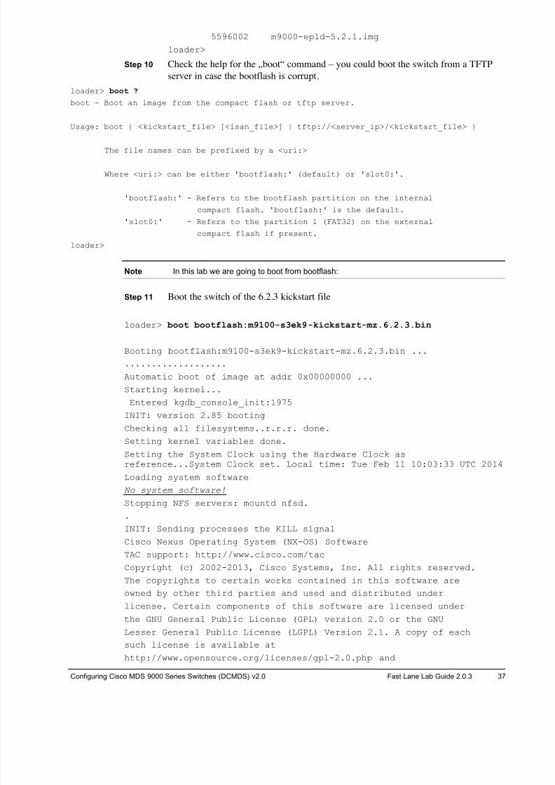
5596002 m9000-epld-5.2.1.img
loader>
Step 10 Check the help for the „boot“ command – you could boot the switch from a TFTP
server in case the bootflash is corrupt.
loader> boot ?
boot - Boot an image from the compact flash or tftp server.
Usage: boot { <kickstart_file> [<isan_file>] | tftp://<server_ip>/<kickstart_file> }
The file names can be prefixed by a <uri:>
Where <uri:> can be either 'bootflash:' (default) or 'slot0:'.
'bootflash:' - Refers to the bootflash partition on the internal
compact flash. 'bootflash:' is the default.
'slot0:' - Refers to the partition 1 (FAT32) on the external
compact flash if present.
loader>
Note In this lab we are going to boot from bootflash:
Step 11 Boot the switch of the 6.2.3 kickstart file
loader> boot bootflash:m9100-s3ek9-kickstart-mz.6.2.3.bin
Booting bootflash:m9100-s3ek9-kickstart-mz.6.2.3.bin ...
...................
Automatic boot of image at addr 0x00000000 ...
Starting kernel...
Entered kgdb_console_init:1975
INIT: version 2.85 booting
Checking all filesystems..r.r.r. done.
Setting kernel variables done.
Setting the System Clock using the Hardware Clock asreference...System Clock set. Local time: Tue Feb 11 10:03:33 UTC 2014
Loading system software
No system software!
Stopping NFS servers: mountd nfsd.
.
INIT: Sending processes the KILL signal
Cisco Nexus Operating System (NX-OS) Software
TAC support: http://www.cisco.com/tac
Copyright (c) 2002-2013, Cisco Systems, Inc. All rights reserved.
The copyrights to certain works contained in this software are
owned by other third parties and used and distributed under
license. Certain components of this software are licensed under
the GNU General Public License (GPL) version 2.0 or the GNU
Lesser General Public License (LGPL) Version 2.1. A copy of each
such license is available at
http://www.opensource.org/licenses/gpl-2.0.php and
8/18/2019 FL_DCMDS_2.0.3_LG(1).pdf
http://slidepdf.com/reader/full/fldcmds203lg1pdf 38/482
38 Configuring Cisco MDS 9000 Series Switches (DCMDS) v2.0 © 2014 Fast Lane and Cisco Systems, Inc.
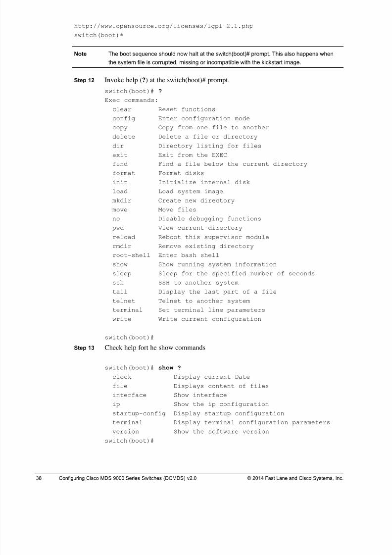
http://www.opensource.org/licenses/lgpl-2.1.php
switch(boot)#
Note The boot sequence should now halt at the switch(boot)# prompt. This also happens when
the system file is corrupted, missing or incompatible with the kickstart image.
Step 12 Invoke help (?) at the switch(boot)# prompt. switch(boot)# ?
Exec commands:
clear Reset functions
config Enter configuration mode
copy Copy from one file to another
delete Delete a file or directory
dir Directory listing for files
exit Exit from the EXEC
find Find a file below the current directory
format Format disks
init Initialize internal disk
load Load system imagemkdir Create new directory
move Move files
no Disable debugging functions
pwd View current directory
reload Reboot this supervisor module
rmdir Remove existing directory
root-shell Enter bash shell
show Show running system information
sleep Sleep for the specified number of seconds
ssh SSH to another system
tail Display the last part of a filetelnet Telnet to another system
terminal Set terminal line parameters
write Write current configuration
switch(boot)#
Step 13 Check help fort he show commands
switch(boot)# show ?
clock Display current Date
file Displays content of filesinterface Show interface
ip Show the ip configuration
startup-config Display startup configuration
terminal Display terminal configuration parameters
version Show the software version
switch(boot)#
8/18/2019 FL_DCMDS_2.0.3_LG(1).pdf
http://slidepdf.com/reader/full/fldcmds203lg1pdf 39/482
Configuring Cisco MDS 9000 Series Switches (DCMDS) v2.0 Fast Lane Lab Guide 2.0.3 39
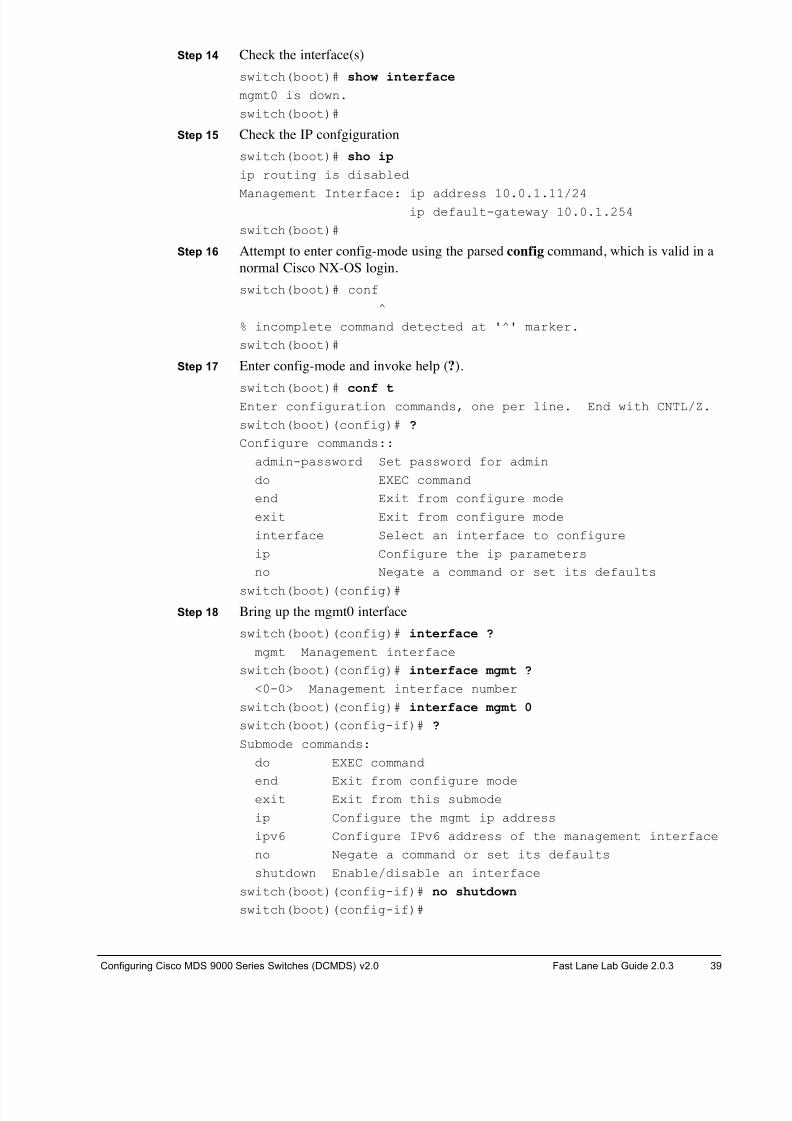
Step 14 Check the interface(s) switch(boot)# show interface
mgmt0 is down.
switch(boot)#
Step 15 Check the IP confgiguration switch(boot)# sho ip
ip routing is disabled
Management Interface: ip address 10.0.1.11/24ip default-gateway 10.0.1.254
switch(boot)#
Step 16 Attempt to enter config-mode using the parsed config command, which is valid in a
normal Cisco NX-OS login. switch(boot)# conf
^
% incomplete command detected at '^' marker.
switch(boot)#
Step 17 Enter config-mode and invoke help (?).
switch(boot)# conf t Enter configuration commands, one per line. End with CNTL/Z.
switch(boot)(config)# ?
Configure commands::
admin-password Set password for admin
do EXEC command
end Exit from configure mode
exit Exit from configure mode
interface Select an interface to configure
ip Configure the ip parameters
no Negate a command or set its defaults
switch(boot)(config)#
Step 18 Bring up the mgmt0 interface
switch(boot)(config)# interface ?
mgmt Management interface
switch(boot)(config)# interface mgmt ?
<0-0> Management interface number
switch(boot)(config)# interface mgmt 0
switch(boot)(config-if)# ?
Submode commands:
do EXEC command
end Exit from configure modeexit Exit from this submode
ip Configure the mgmt ip address
ipv6 Configure IPv6 address of the management interface
no Negate a command or set its defaults
shutdown Enable/disable an interface
switch(boot)(config-if)# no shutdown
switch(boot)(config-if)#
8/18/2019 FL_DCMDS_2.0.3_LG(1).pdf
http://slidepdf.com/reader/full/fldcmds203lg1pdf 40/482
40 Configuring Cisco MDS 9000 Series Switches (DCMDS) v2.0 © 2014 Fast Lane and Cisco Systems, Inc.
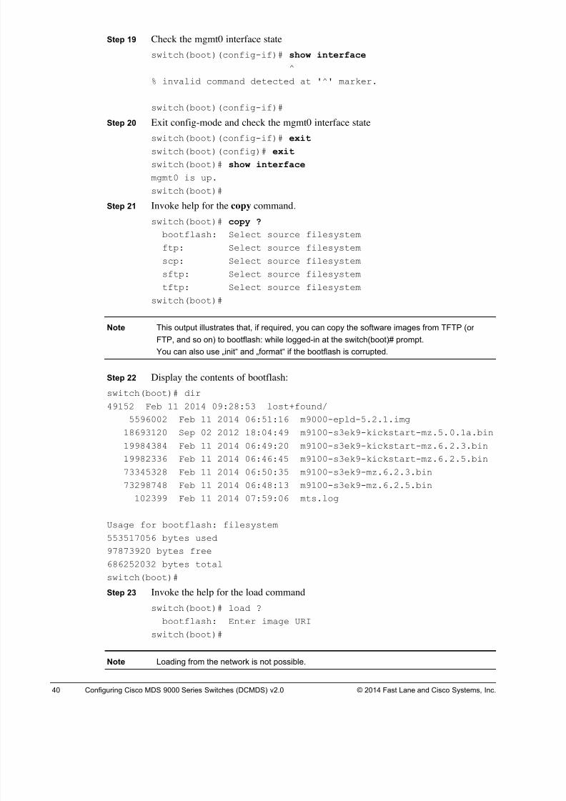
Step 19 Check the mgmt0 interface state switch(boot)(config-if)# show interface
^
% invalid command detected at '^' marker.
switch(boot)(config-if)#
Step 20 Exit config-mode and check the mgmt0 interface state
switch(boot)(config-if)# exitswitch(boot)(config)# exit
switch(boot)# show interface
mgmt0 is up.
switch(boot)#
Step 21 Invoke help for the copy command. switch(boot)# copy ?
bootflash: Select source filesystem
ftp: Select source filesystem
scp: Select source filesystem
sftp: Select source filesystem
tftp: Select source filesystem
switch(boot)#
Note This output illustrates that, if required, you can copy the software images from TFTP (or
FTP, and so on) to bootflash: while logged-in at the switch(boot)# prompt.
You can also use „init“ and „format“ if the bootflash is corrupted.
Step 22 Display the contents of bootflash: switch(boot)# dir
49152 Feb 11 2014 09:28:53 lost+found/
5596002 Feb 11 2014 06:51:16 m9000-epld-5.2.1.img18693120 Sep 02 2012 18:04:49 m9100-s3ek9-kickstart-mz.5.0.1a.bin
19984384 Feb 11 2014 06:49:20 m9100-s3ek9-kickstart-mz.6.2.3.bin
19982336 Feb 11 2014 06:46:45 m9100-s3ek9-kickstart-mz.6.2.5.bin
73345328 Feb 11 2014 06:50:35 m9100-s3ek9-mz.6.2.3.bin
73298748 Feb 11 2014 06:48:13 m9100-s3ek9-mz.6.2.5.bin
102399 Feb 11 2014 07:59:06 mts.log
Usage for bootflash: filesystem
553517056 bytes used
97873920 bytes free
686252032 bytes total
switch(boot)#
Step 23 Invoke the help for the load command switch(boot)# load ?
bootflash: Enter image URI
switch(boot)#
Note Loading from the network is not possible.
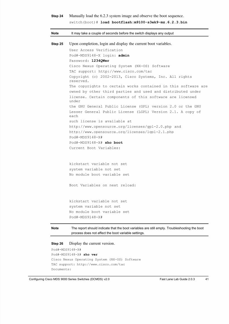
8/18/2019 FL_DCMDS_2.0.3_LG(1).pdf
http://slidepdf.com/reader/full/fldcmds203lg1pdf 41/482
Configuring Cisco MDS 9000 Series Switches (DCMDS) v2.0 Fast Lane Lab Guide 2.0.3 41
Step 24 Manually load the 6.2.3 system image and observe the boot sequence. switch(boot)# load bootflash:m9100-s3ek9-mz.6.2.3.bin
Note It may take a couple of seconds before the switch displays any output
Step 25 Upon completion, login and display the current boot variables. User Access Verification
Pod#-MDS9148-X login: admin Password: 1234QWer
Cisco Nexus Operating System (NX-OS) Software
TAC support: http://www.cisco.com/tac
Copyright (c) 2002-2013, Cisco Systems, Inc. All rightsreserved.
The copyrights to certain works contained in this software are
owned by other third parties and used and distributed under
license. Certain components of this software are licensedunder
the GNU General Public License (GPL) version 2.0 or the GNU
Lesser General Public License (LGPL) Version 2.1. A copy ofeach
such license is available at
http://www.opensource.org/licenses/gpl-2.0.php and
http://www.opensource.org/licenses/lgpl-2.1.php
Pod#-MDS9148-X#
Pod#-MDS9148-X# sho boot
Current Boot Variables:
kickstart variable not set
system variable not setNo module boot variable set
Boot Variables on next reload:
kickstart variable not set
system variable not set
No module boot variable set
Pod#-MDS9148-X#
Note The report should indicate that the boot variables are still empty. Troubleshooting the boot
process does not affect the boot variable settings.
Step 26 Display the current version. Pod#-MDS9148-X#
Pod#-MDS9148-X# sho ver
Cisco Nexus Operating System (NX-OS) Software
TAC support: http://www.cisco.com/tac
Documents:
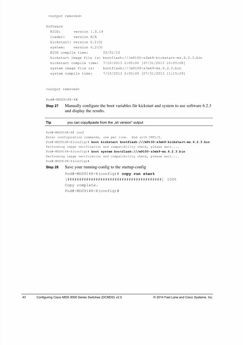
8/18/2019 FL_DCMDS_2.0.3_LG(1).pdf
http://slidepdf.com/reader/full/fldcmds203lg1pdf 42/482
42 Configuring Cisco MDS 9000 Series Switches (DCMDS) v2.0 © 2014 Fast Lane and Cisco Systems, Inc.
<output removed>
Software
BIOS: version 1.0.19
loader: version N/A
kickstart: version 6.2(3)
system: version 6.2(3)
BIOS compile time: 02/01/10
kickstart image file is: bootflash:///m9100-s3ek9-kickstart-mz.6.2.3.bin
kickstart compile time: 7/10/2013 2:00:00 [07/31/2013 10:05:08]
system image file is: bootflash:///m9100-s3ek9-mz.6.2.3.bin
system compile time: 7/10/2013 2:00:00 [07/31/2013 11:15:29]
<output removed>
Pod#-MDS9148-X#
Step 27 Manually configure the boot variables für kickstart and system to use software 6.2.3
and display the results.
Tip you can copy&paste from the „sh version“ output
Pod#-MDS9148-X# conf
Enter configuration commands, one per line. End with CNTL/Z.
Pod#-MDS9148-X(config)# boot kickstart bootflash:///m9100-s3ek9-kickstart-mz.6.2.3.bin
Performing image verification and compatibility check, please wait....
Pod#-MDS9148-X(config)# boot system bootflash:///m9100-s3ek9-mz.6.2.3.bin
Performing image verification and compatibility check, please wait....
Pod#-MDS9148-X(config)#
Step 28 Save your running-config to the startup-config Pod#-MDS9148-X(config)# copy run start
[########################################] 100%Copy complete.
Pod#-MDS9148-X(config)#
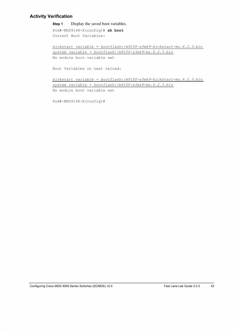
8/18/2019 FL_DCMDS_2.0.3_LG(1).pdf
http://slidepdf.com/reader/full/fldcmds203lg1pdf 43/482
Configuring Cisco MDS 9000 Series Switches (DCMDS) v2.0 Fast Lane Lab Guide 2.0.3 43
Activity Verification
Step 1 Display the saved boot variables. Pod#-MDS9148-X(config)# sh boot
Current Boot Variables:
kickstart variable = bootflash:/m9100-s3ek9-kickstart-mz.6.2.3.bin
system variable = bootflash:/m9100-s3ek9-mz.6.2.3.bin
No module boot variable set
Boot Variables on next reload:
kickstart variable = bootflash:/m9100-s3ek9-kickstart-mz.6.2.3.bin
system variable = bootflash:/m9100-s3ek9-mz.6.2.3.bin
No module boot variable set
Pod#-MDS9148-X(config)#
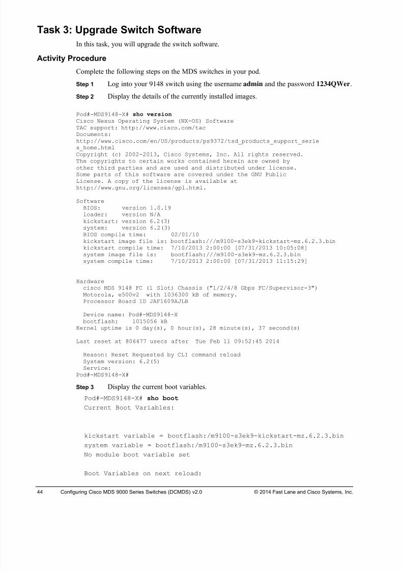
8/18/2019 FL_DCMDS_2.0.3_LG(1).pdf
http://slidepdf.com/reader/full/fldcmds203lg1pdf 44/482
44 Configuring Cisco MDS 9000 Series Switches (DCMDS) v2.0 © 2014 Fast Lane and Cisco Systems, Inc.
Task 3: Upgrade Switch Software
In this task, you will upgrade the switch software.
Activity Procedure
Complete the following steps on the MDS switches in your pod.
Step 1 Log into your 9148 switch using the username admin and the password 1234QWer.
Step 2Display the details of the currently installed images.
Pod#-MDS9148-X# sho version Cisco Nexus Operating System (NX-OS) SoftwareTAC support: http://www.cisco.com/tacDocuments:http://www.cisco.com/en/US/products/ps9372/tsd_products_support_series_home.htmlCopyright (c) 2002-2013, Cisco Systems, Inc. All rights reserved.The copyrights to certain works contained herein are owned byother third parties and are used and distributed under license.Some parts of this software are covered under the GNU PublicLicense. A copy of the license is available athttp://www.gnu.org/licenses/gpl.html.
SoftwareBIOS: version 1.0.19loader: version N/Akickstart: version 6.2(3)system: version 6.2(3)BIOS compile time: 02/01/10kickstart image file is: bootflash:///m9100-s3ek9-kickstart-mz.6.2.3.binkickstart compile time: 7/10/2013 2:00:00 [07/31/2013 10:05:08]system image file is: bootflash:///m9100-s3ek9-mz.6.2.3.binsystem compile time: 7/10/2013 2:00:00 [07/31/2013 11:15:29]
Hardwarecisco MDS 9148 FC (1 Slot) Chassis ("1/2/4/8 Gbps FC/Supervisor-3")Motorola, e500v2 with 1036300 kB of memory.
Processor Board ID JAF1609AJLB
Device name: Pod#-MDS9148-Xbootflash: 1015056 kB
Kernel uptime is 0 day(s), 0 hour(s), 28 minute(s), 37 second(s)
Last reset at 806477 usecs after Tue Feb 11 09:52:45 2014
Reason: Reset Requested by CLI command reloadSystem version: 6.2(5)Service:
Pod#-MDS9148-X#
Step 3 Display the current boot variables.
Pod#-MDS9148-X# sho bootCurrent Boot Variables:
kickstart variable = bootflash:/m9100-s3ek9-kickstart-mz.6.2.3.bin
system variable = bootflash:/m9100-s3ek9-mz.6.2.3.bin
No module boot variable set
Boot Variables on next reload:
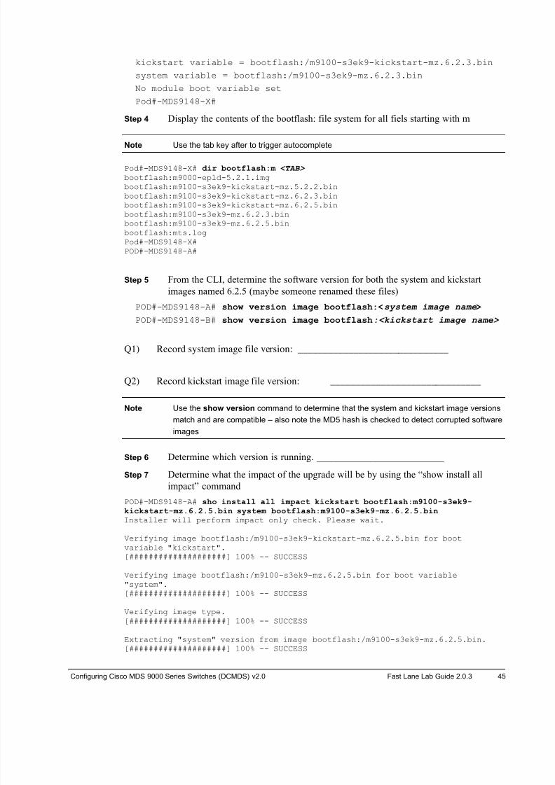
8/18/2019 FL_DCMDS_2.0.3_LG(1).pdf
http://slidepdf.com/reader/full/fldcmds203lg1pdf 45/482
Configuring Cisco MDS 9000 Series Switches (DCMDS) v2.0 Fast Lane Lab Guide 2.0.3 45
kickstart variable = bootflash:/m9100-s3ek9-kickstart-mz.6.2.3.bin
system variable = bootflash:/m9100-s3ek9-mz.6.2.3.bin
No module boot variable set
Pod#-MDS9148-X#
Step 4 Display the contents of the bootflash: file system for all fiels starting with m
Note Use the tab key after to trigger autocomplete
Pod#-MDS9148-X# dir bootflash:m <TAB> bootflash:m9000-epld-5.2.1.imgbootflash:m9100-s3ek9-kickstart-mz.5.2.2.binbootflash:m9100-s3ek9-kickstart-mz.6.2.3.binbootflash:m9100-s3ek9-kickstart-mz.6.2.5.binbootflash:m9100-s3ek9-mz.6.2.3.binbootflash:m9100-s3ek9-mz.6.2.5.binbootflash:mts.logPod#-MDS9148-X#POD#-MDS9148-A#
Step 5 From the CLI, determine the software version for both the system and kickstart
images named 6.2.5 (maybe someone renamed these files)
POD#-MDS9148-A# show version image bootflash:<system image name>
POD#-MDS9148-B# show version image bootflash:<kickstart image name>
Q1) Record system image file version: ______________________________
Q2) Record kickstart image file version: ______________________________
Note Use the show version command to determine that the system and kickstart image versions
match and are compatible – also note the MD5 hash is checked to detect corrupted software
images
Step 6 Determine which version is running. __________________________
Step 7 Determine what the impact of the upgrade will be by using the “show install all
impact” command
POD#-MDS9148-A# sho install all impact kickstart bootflash:m9100-s3ek9-
kickstart-mz.6.2.5.bin system bootflash:m9100-s3ek9-mz.6.2.5.bin Installer will perform impact only check. Please wait.
Verifying image bootflash:/m9100-s3ek9-kickstart-mz.6.2.5.bin for boot
variable "kickstart".[####################] 100% -- SUCCESS
Verifying image bootflash:/m9100-s3ek9-mz.6.2.5.bin for boot variable"system".[####################] 100% -- SUCCESS
Verifying image type.[####################] 100% -- SUCCESS
Extracting "system" version from image bootflash:/m9100-s3ek9-mz.6.2.5.bin.[####################] 100% -- SUCCESS
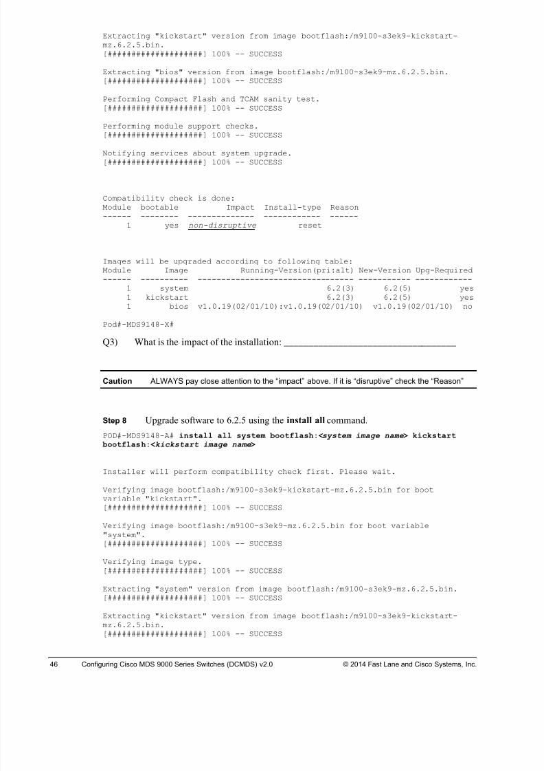
8/18/2019 FL_DCMDS_2.0.3_LG(1).pdf
http://slidepdf.com/reader/full/fldcmds203lg1pdf 46/482
46 Configuring Cisco MDS 9000 Series Switches (DCMDS) v2.0 © 2014 Fast Lane and Cisco Systems, Inc.
Extracting "kickstart" version from image bootflash:/m9100-s3ek9-kickstart-mz.6.2.5.bin.[####################] 100% -- SUCCESS
Extracting "bios" version from image bootflash:/m9100-s3ek9-mz.6.2.5.bin.[####################] 100% -- SUCCESS
Performing Compact Flash and TCAM sanity test.[####################] 100% -- SUCCESS
Performing module support checks.
[####################] 100% -- SUCCESS
Notifying services about system upgrade.[####################] 100% -- SUCCESS
Compatibility check is done:Module bootable Impact Install-type Reason------ -------- -------------- ------------ ------
1 yes non-disruptive reset
Images will be upgraded according to following table:
Module Image Running-Version(pri:alt) New-Version Upg-Required------ ---------- --------------------------------- ----------- ------------
1 system 6.2(3) 6.2(5) yes1 kickstart 6.2(3) 6.2(5) yes1 bios v1.0.19(02/01/10):v1.0.19(02/01/10) v1.0.19(02/01/10) no
Pod#-MDS9148-X#
Q3) What is the impact of the installation: ___________________________________
Caution ALWAYS pay close attention to the “impact” above. If it is “disruptive” check the “Reason”
Step 8 Upgrade software to 6.2.5 using the install all command.
POD#-MDS9148-A# install all system bootflash:<system image name> kickstart bootflash:<kickstart image name>
Installer will perform compatibility check first. Please wait.
Verifying image bootflash:/m9100-s3ek9-kickstart-mz.6.2.5.bin for bootvariable "kickstart".[####################] 100% -- SUCCESS
Verifying image bootflash:/m9100-s3ek9-mz.6.2.5.bin for boot variable"system".[####################] 100% -- SUCCESS
Verifying image type.[####################] 100% -- SUCCESS
Extracting "system" version from image bootflash:/m9100-s3ek9-mz.6.2.5.bin.[####################] 100% -- SUCCESS
Extracting "kickstart" version from image bootflash:/m9100-s3ek9-kickstart-mz.6.2.5.bin.[####################] 100% -- SUCCESS
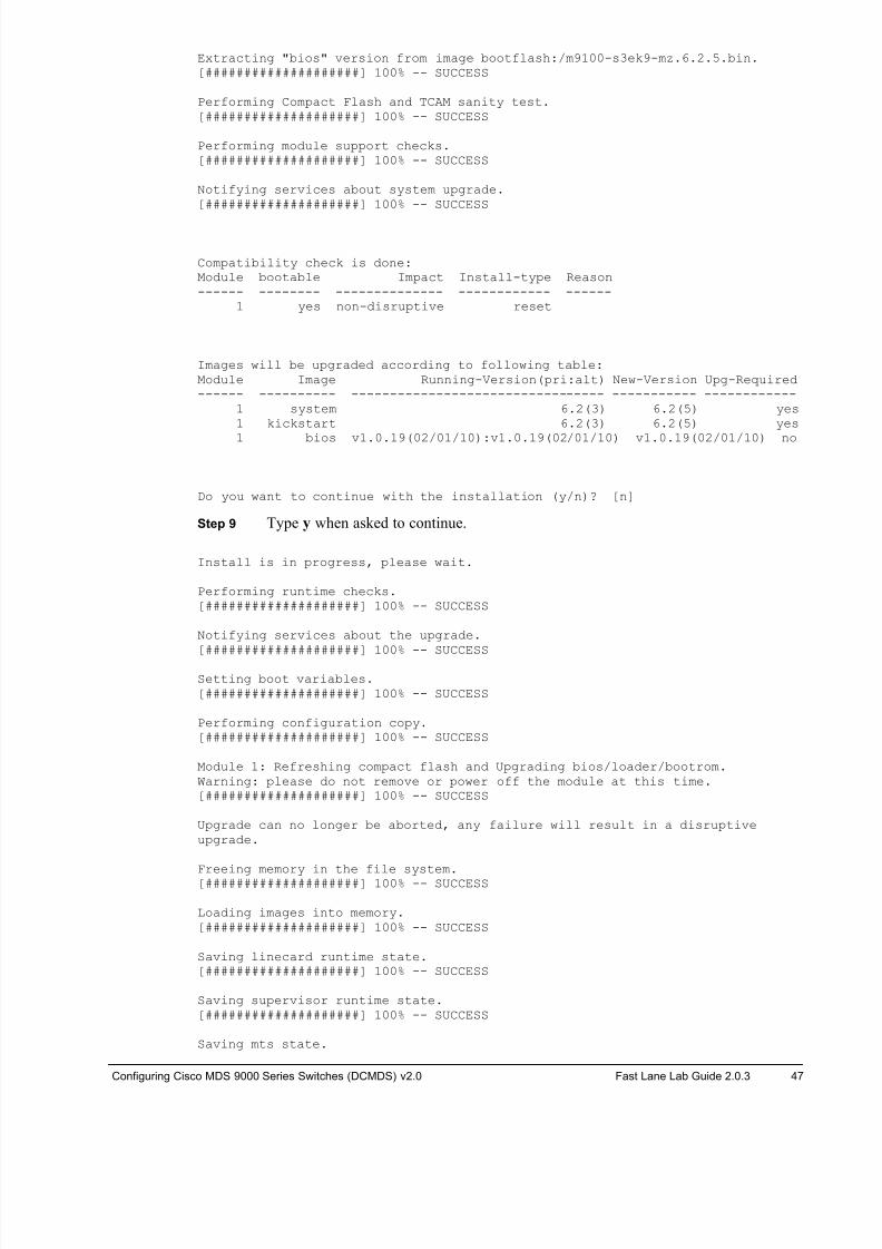
8/18/2019 FL_DCMDS_2.0.3_LG(1).pdf
http://slidepdf.com/reader/full/fldcmds203lg1pdf 47/482
Configuring Cisco MDS 9000 Series Switches (DCMDS) v2.0 Fast Lane Lab Guide 2.0.3 47
Extracting "bios" version from image bootflash:/m9100-s3ek9-mz.6.2.5.bin.[####################] 100% -- SUCCESS
Performing Compact Flash and TCAM sanity test.[####################] 100% -- SUCCESS
Performing module support checks.[####################] 100% -- SUCCESS
Notifying services about system upgrade.[####################] 100% -- SUCCESS
Compatibility check is done:Module bootable Impact Install-type Reason------ -------- -------------- ------------ ------
1 yes non-disruptive reset
Images will be upgraded according to following table:Module Image Running-Version(pri:alt) New-Version Upg-Required------ ---------- --------------------------------- ----------- ------------
1 system 6.2(3) 6.2(5) yes1 kickstart 6.2(3) 6.2(5) yes
1 bios v1.0.19(02/01/10):v1.0.19(02/01/10) v1.0.19(02/01/10) no
Do you want to continue with the installation (y/n)? [n]
Step 9 Type y when asked to continue.
Install is in progress, please wait.
Performing runtime checks.[####################] 100% -- SUCCESS
Notifying services about the upgrade.
[####################] 100% -- SUCCESS
Setting boot variables.[####################] 100% -- SUCCESS
Performing configuration copy.[####################] 100% -- SUCCESS
Module 1: Refreshing compact flash and Upgrading bios/loader/bootrom.Warning: please do not remove or power off the module at this time.[####################] 100% -- SUCCESS
Upgrade can no longer be aborted, any failure will result in a disruptiveupgrade.
Freeing memory in the file system.[####################] 100% -- SUCCESS
Loading images into memory.[####################] 100% -- SUCCESS
Saving linecard runtime state.[####################] 100% -- SUCCESS
Saving supervisor runtime state.[####################] 100% -- SUCCESS
Saving mts state.
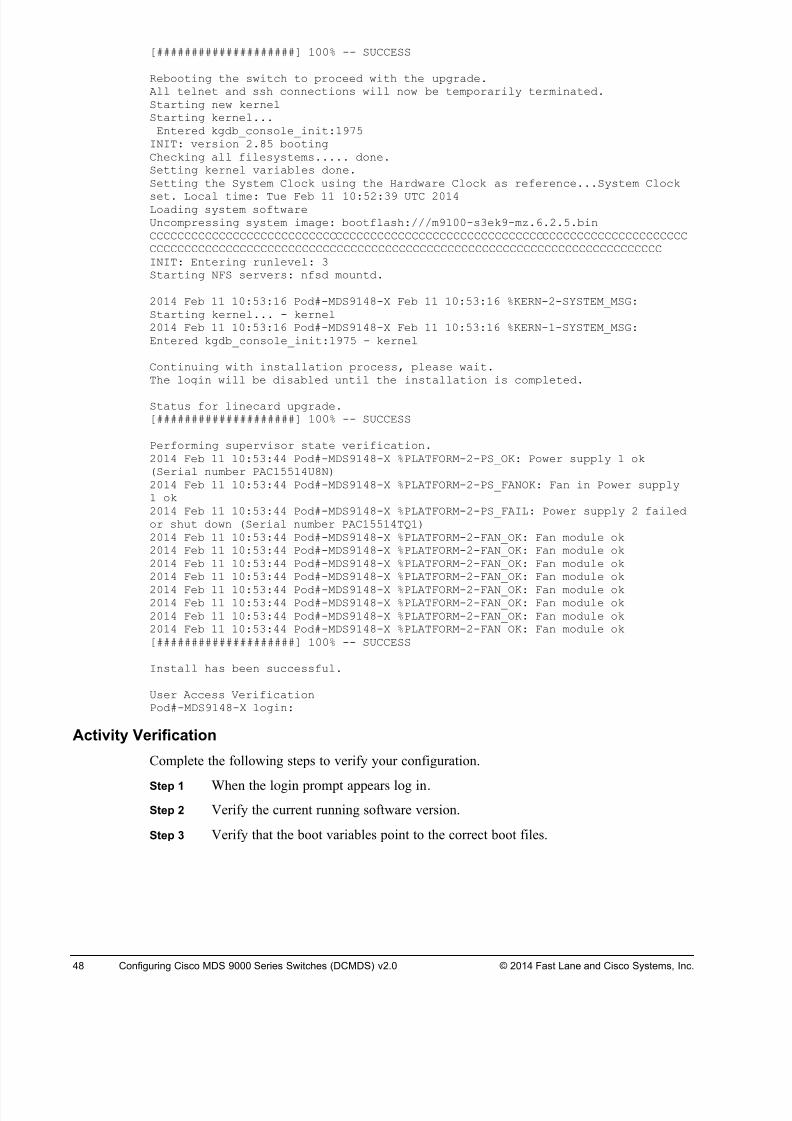
8/18/2019 FL_DCMDS_2.0.3_LG(1).pdf
http://slidepdf.com/reader/full/fldcmds203lg1pdf 48/482
48 Configuring Cisco MDS 9000 Series Switches (DCMDS) v2.0 © 2014 Fast Lane and Cisco Systems, Inc.
[####################] 100% -- SUCCESS
Rebooting the switch to proceed with the upgrade.All telnet and ssh connections will now be temporarily terminated.Starting new kernelStarting kernel...Entered kgdb_console_init:1975
INIT: version 2.85 bootingChecking all filesystems..... done.Setting kernel variables done.Setting the System Clock using the Hardware Clock as reference...System Clock
set. Local time: Tue Feb 11 10:52:39 UTC 2014Loading system softwareUncompressing system image: bootflash:///m9100-s3ek9-mz.6.2.5.binCCCCCCCCCCCCCCCCCCCCCCCCCCCCCCCCCCCCCCCCCCCCCCCCCCCCCCCCCCCCCCCCCCCCCCCCCCCCCCCCCCCCCCCCCCCCCCCCCCCCCCCCCCCCCCCCCCCCCCCCCCCCCCCCCCCCCCCCCCCCCCCCCCCCCCCCINIT: Entering runlevel: 3Starting NFS servers: nfsd mountd.
2014 Feb 11 10:53:16 Pod#-MDS9148-X Feb 11 10:53:16 %KERN-2-SYSTEM_MSG:Starting kernel... - kernel2014 Feb 11 10:53:16 Pod#-MDS9148-X Feb 11 10:53:16 %KERN-1-SYSTEM_MSG:Entered kgdb_console_init:1975 - kernel
Continuing with installation process, please wait.The login will be disabled until the installation is completed.
Status for linecard upgrade.[####################] 100% -- SUCCESS
Performing supervisor state verification.2014 Feb 11 10:53:44 Pod#-MDS9148-X %PLATFORM-2-PS_OK: Power supply 1 ok(Serial number PAC15514U8N)2014 Feb 11 10:53:44 Pod#-MDS9148-X %PLATFORM-2-PS_FANOK: Fan in Power supply1 ok2014 Feb 11 10:53:44 Pod#-MDS9148-X %PLATFORM-2-PS_FAIL: Power supply 2 failedor shut down (Serial number PAC15514TQ1)2014 Feb 11 10:53:44 Pod#-MDS9148-X %PLATFORM-2-FAN_OK: Fan module ok2014 Feb 11 10:53:44 Pod#-MDS9148-X %PLATFORM-2-FAN_OK: Fan module ok2014 Feb 11 10:53:44 Pod#-MDS9148-X %PLATFORM-2-FAN_OK: Fan module ok2014 Feb 11 10:53:44 Pod#-MDS9148-X %PLATFORM-2-FAN_OK: Fan module ok
2014 Feb 11 10:53:44 Pod#-MDS9148-X %PLATFORM-2-FAN_OK: Fan module ok2014 Feb 11 10:53:44 Pod#-MDS9148-X %PLATFORM-2-FAN_OK: Fan module ok2014 Feb 11 10:53:44 Pod#-MDS9148-X %PLATFORM-2-FAN_OK: Fan module ok2014 Feb 11 10:53:44 Pod#-MDS9148-X %PLATFORM-2-FAN_OK: Fan module ok[####################] 100% -- SUCCESS
Install has been successful.
User Access VerificationPod#-MDS9148-X login:
Activity Verification
Complete the following steps to verify your configuration.
Step 1 When the login prompt appears log in.
Step 2 Verify the current running software version.
Step 3 Verify that the boot variables point to the correct boot files.
8/18/2019 FL_DCMDS_2.0.3_LG(1).pdf
http://slidepdf.com/reader/full/fldcmds203lg1pdf 49/482
Configuring Cisco MDS 9000 Series Switches (DCMDS) v2.0 Fast Lane Lab Guide 2.0.3 49
Task 3: Cleanup
In this task, you prepare your lab for the next exercise.
Activity Procedure
Complete the following steps.
Step 1 Open a console session to your assigned switch (MDS9148-A or MDS9148-B) by
clicking the blue switch icon in the remote lab GUI.
Switch login: admin
Password: 1234QWer
Step 2 Clear the current startup configuration ON YOUR 9148s ONLY, DO NOT CLEAR
THE CORE 9222is!!! .
# write erase
The following message is displayed:
Warning: This command will erase the startup-configuration.
Do you wish to proceed anyway? [y/n] [N]
Type y to proceed.
Step 3 Reboot the 9148 switch.# reload
This command will reboot the system. (y/n)?
Type y to proceed.
8/18/2019 FL_DCMDS_2.0.3_LG(1).pdf
http://slidepdf.com/reader/full/fldcmds203lg1pdf 50/482
50 Configuring Cisco MDS 9000 Series Switches (DCMDS) v2.0 © 2014 Fast Lane and Cisco Systems, Inc.
Lab 2-3: Install Cisco Prime DCNM 6.2 Complete this lab activity to practice what you learned in the related lesson.
As of Cisco DCNM Release 5.2, Cisco Fabric Manager and Cisco DCNM for LAN were
merged into one unified product called Cisco DCNM that can manage both LAN and SAN
environments. As of Cisco Prime DCNM Release 6.2, the name Cisco Prime DCNM-SAN
Client replaces the name Cisco Fabric Manager. Cisco Prime DCNM also contains a
component called Device Manager that you will use throughout the lab exercises.
You will use Cisco Prime DCNM Release 6.2(5) in these labs.
Cisco Prime DCNM is a management system for the Cisco Unified Fabric. Cisco Prime DCNM
consists of four components, which are the Cisco Prime DCNM Unified Web Client, Cisco
Prime DCNM-SAN Client, Cisco Prime DCNM-LAN Client, and Cisco Device Manager.
Cisco Prime DCNM enables you to provision, monitor, and troubleshoot the data center
network infrastructure.
Activity Objective
In this activity, you will install and set up Cisco Prime DCNM for SAN management. Upon
completing this exercise, you will be able to meet the following objectives:
• Launch the Cisco Prime DCNM Unified Web Client
• Launch the Cisco Prime DCNM-SAN Client
• Discover SAN devices through the Cisco Prime DCNM-SAN Client
• Launch Cisco Device Manager for use in the following labs
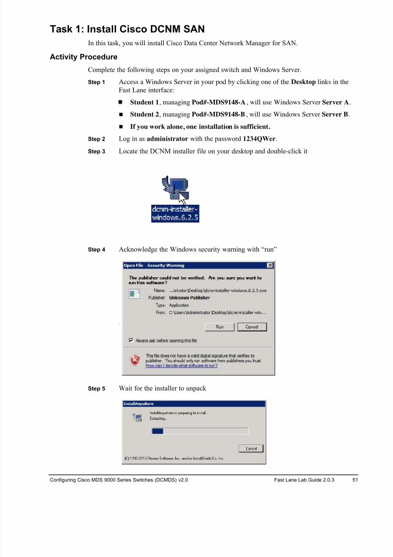
8/18/2019 FL_DCMDS_2.0.3_LG(1).pdf
http://slidepdf.com/reader/full/fldcmds203lg1pdf 51/482
Configuring Cisco MDS 9000 Series Switches (DCMDS) v2.0 Fast Lane Lab Guide 2.0.3 51
Task 1: Install Cisco DCNM SAN
In this task, you will install Cisco Data Center Network Manager for SAN.
Activity Procedure
Complete the following steps on your assigned switch and Windows Server.
Step 1 Access a Windows Server in your pod by clicking one of the Desktop links in the
Fast Lane interface:
Student 1, managing Pod#-MDS9148-A , will use Windows Server Server A.
! Student 2, managing Pod#-MDS9148-B, will use Windows Server Server B.
! If you work alone, one installation is sufficient.
Step 2 Log in as administrator with the password 1234QWer.
Step 3 Locate the DCNM installer file on your desktop and double-click it
Step 4 Acknowledge the Windows security warning with “run”
Step 5 Wait for the installer to unpack
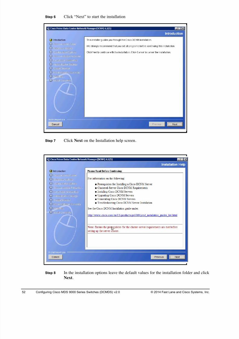
8/18/2019 FL_DCMDS_2.0.3_LG(1).pdf
http://slidepdf.com/reader/full/fldcmds203lg1pdf 52/482
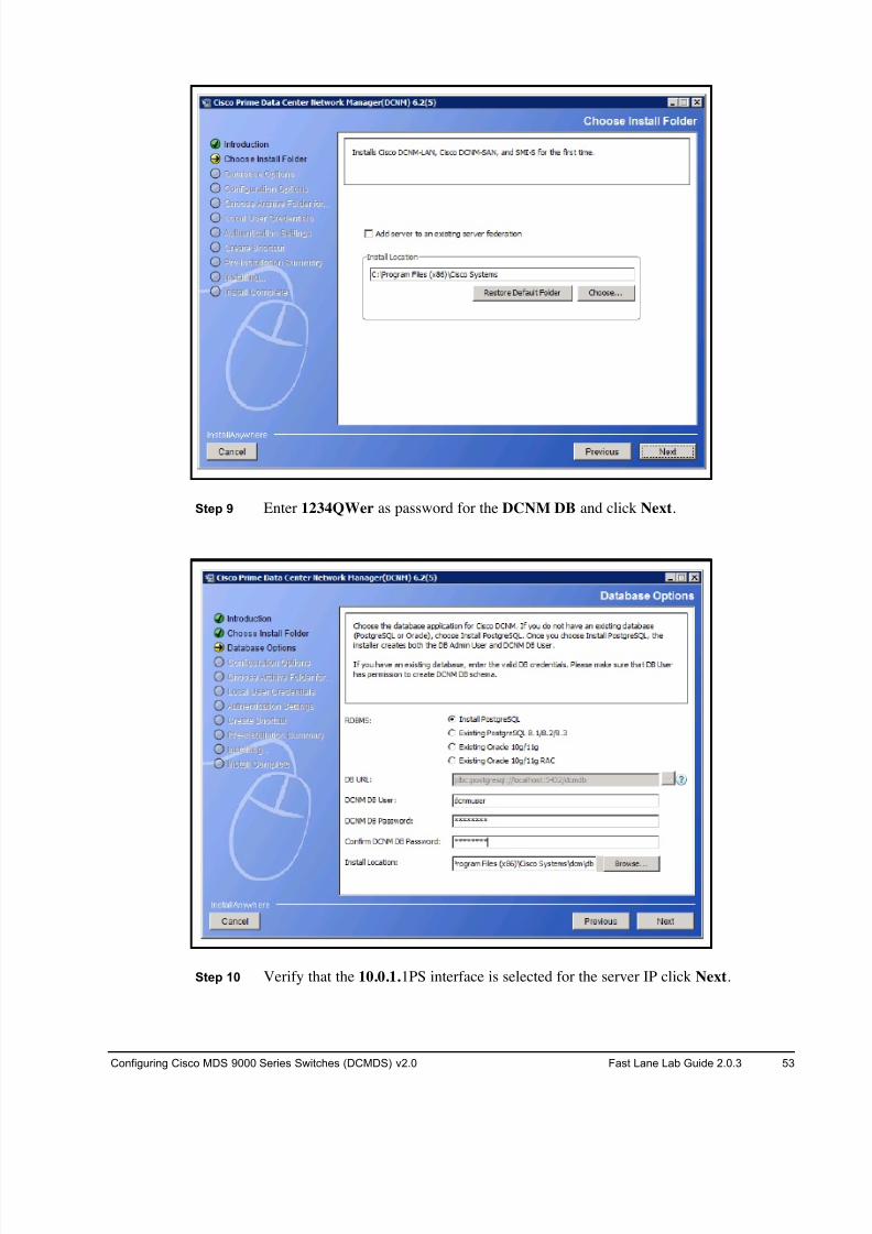
8/18/2019 FL_DCMDS_2.0.3_LG(1).pdf
http://slidepdf.com/reader/full/fldcmds203lg1pdf 53/482
Configuring Cisco MDS 9000 Series Switches (DCMDS) v2.0 Fast Lane Lab Guide 2.0.3 53
Step 9 Enter 1234QWer as password for the DCNM DB and click Next.
Step 10 Verify that the 10.0.1.1PS interface is selected for the server IP click Next.
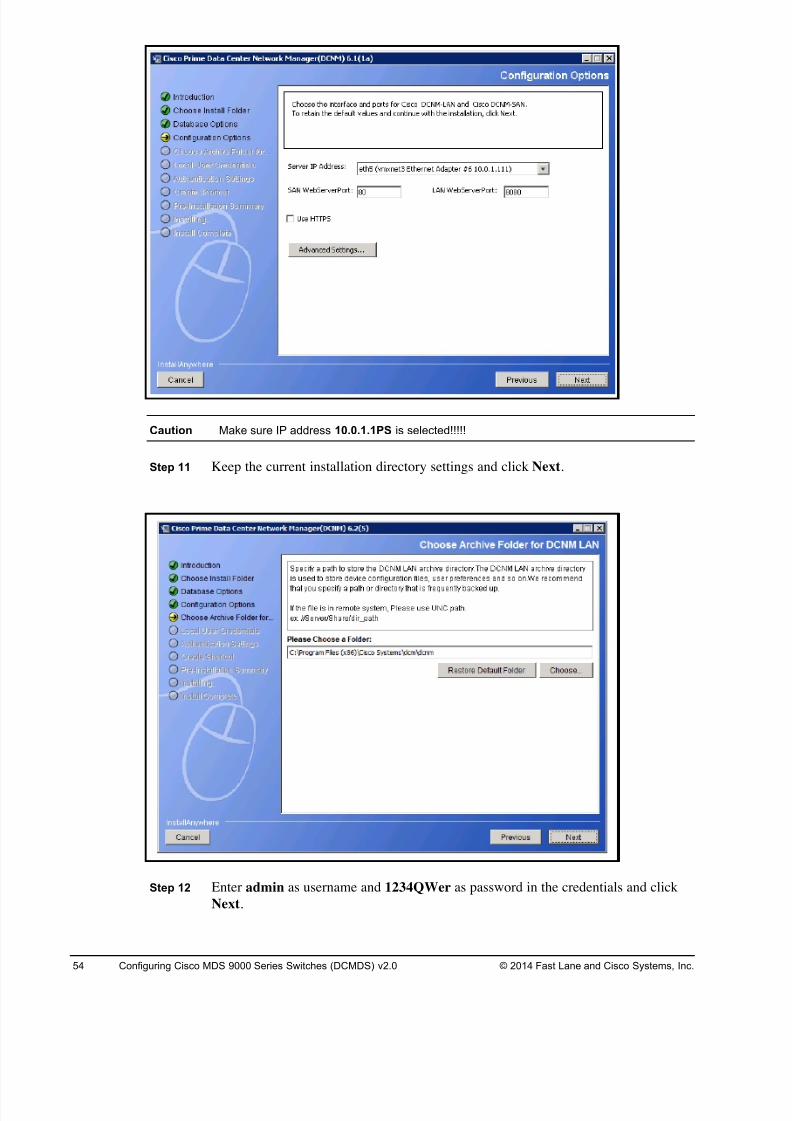
8/18/2019 FL_DCMDS_2.0.3_LG(1).pdf
http://slidepdf.com/reader/full/fldcmds203lg1pdf 54/482
54 Configuring Cisco MDS 9000 Series Switches (DCMDS) v2.0 © 2014 Fast Lane and Cisco Systems, Inc.
Caution Make sure IP address 10.0.1.1PS is selected!!!!!
Step 11 Keep the current installation directory settings and click Next.
Step 12 Enter admin as username and 1234QWer as password in the credentials and click
Next.
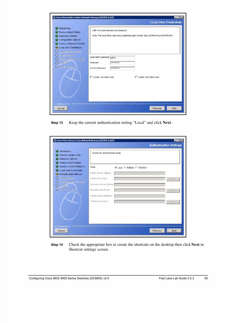
8/18/2019 FL_DCMDS_2.0.3_LG(1).pdf
http://slidepdf.com/reader/full/fldcmds203lg1pdf 55/482
Configuring Cisco MDS 9000 Series Switches (DCMDS) v2.0 Fast Lane Lab Guide 2.0.3 55
Step 13 Keep the current authentication setting “Local” and click Next.
Step 14 Check the appropriate box to create the shortcuts on the desktop then click Next in
Shortcut settings screen.
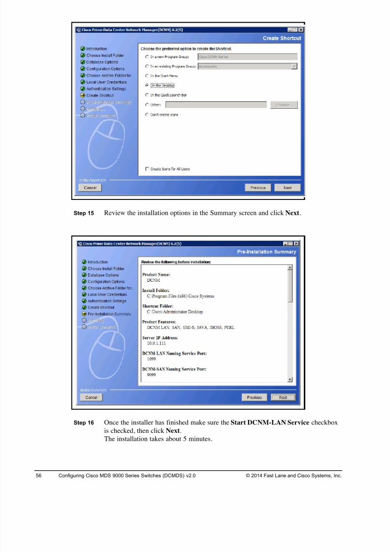
8/18/2019 FL_DCMDS_2.0.3_LG(1).pdf
http://slidepdf.com/reader/full/fldcmds203lg1pdf 56/482
56 Configuring Cisco MDS 9000 Series Switches (DCMDS) v2.0 © 2014 Fast Lane and Cisco Systems, Inc.
Step 15 Review the installation options in the Summary screen and click Next.
Step 16 Once the installer has finished make sure the Start DCNM-LAN Service checkbox
is checked, then click Next.
The installation takes about 5 minutes.
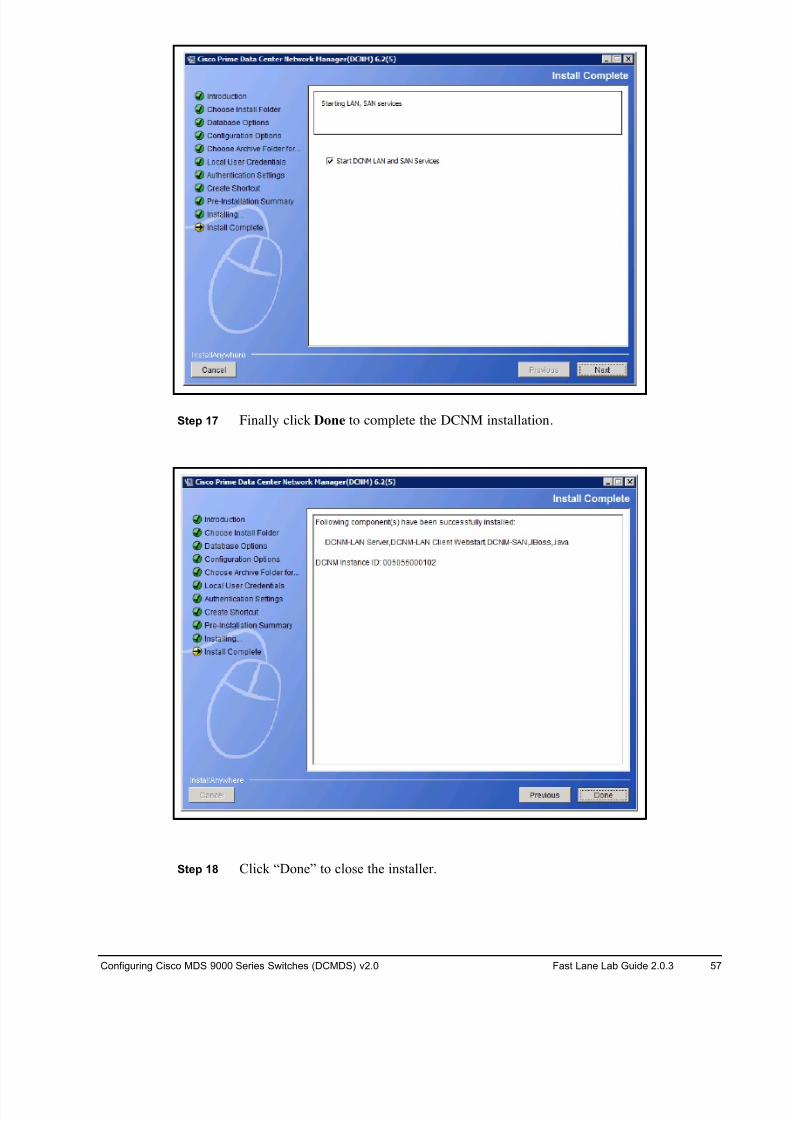
8/18/2019 FL_DCMDS_2.0.3_LG(1).pdf
http://slidepdf.com/reader/full/fldcmds203lg1pdf 57/482
Configuring Cisco MDS 9000 Series Switches (DCMDS) v2.0 Fast Lane Lab Guide 2.0.3 57
Step 17 Finally click Done to complete the DCNM installation.
Step 18 Click “Done” to close the installer.
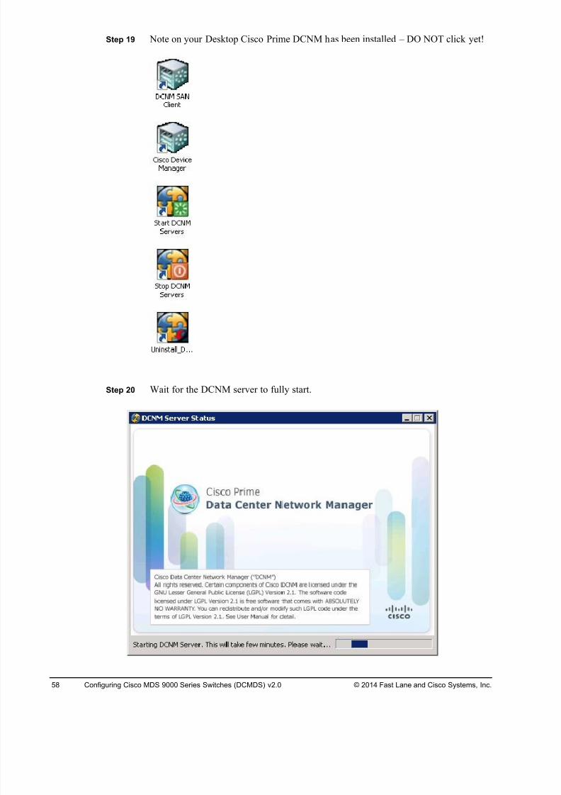
8/18/2019 FL_DCMDS_2.0.3_LG(1).pdf
http://slidepdf.com/reader/full/fldcmds203lg1pdf 58/482
58 Configuring Cisco MDS 9000 Series Switches (DCMDS) v2.0 © 2014 Fast Lane and Cisco Systems, Inc.
Step 19 Note on your Desktop Cisco Prime DCNM has been installed – DO NOT click yet!
Step 20 Wait for the DCNM server to fully start.
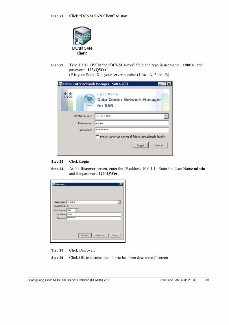
8/18/2019 FL_DCMDS_2.0.3_LG(1).pdf
http://slidepdf.com/reader/full/fldcmds203lg1pdf 59/482
Configuring Cisco MDS 9000 Series Switches (DCMDS) v2.0 Fast Lane Lab Guide 2.0.3 59
Step 21 Click “DCNM SAN Client” to start
Step 22 Type 10.0.1.1PX in the “DCNM server” field and type in username “admin” and
password “1234QWer”.
(P is your Pod#, X is your server number (1 for –A, 2 for –B)
Step 23 Click Login.
Step 24 At the Discover screen, enter the IP address 10.0.1.1. Enter the User Name admin
and the password 1234QWer.
Step 25 Click Discover.
Step 26 Click OK to dismiss the “fabric has been discovered” screen
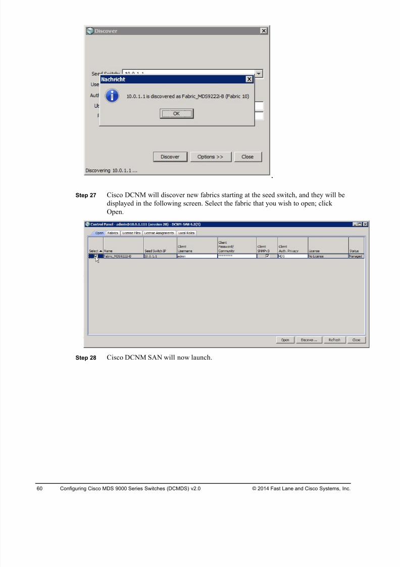
8/18/2019 FL_DCMDS_2.0.3_LG(1).pdf
http://slidepdf.com/reader/full/fldcmds203lg1pdf 60/482
60 Configuring Cisco MDS 9000 Series Switches (DCMDS) v2.0 © 2014 Fast Lane and Cisco Systems, Inc.
Step 27 Cisco DCNM will discover new fabrics starting at the seed switch, and they will be
displayed in the following screen. Select the fabric that you wish to open; click
Open.
Step 28 Cisco DCNM SAN will now launch.
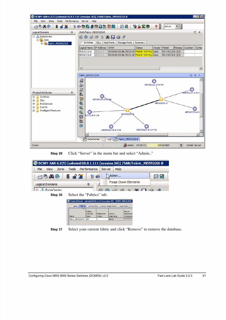
8/18/2019 FL_DCMDS_2.0.3_LG(1).pdf
http://slidepdf.com/reader/full/fldcmds203lg1pdf 61/482
Configuring Cisco MDS 9000 Series Switches (DCMDS) v2.0 Fast Lane Lab Guide 2.0.3 61
Step 29 Click “Server” in the menu bar and select “Admin..”
Step 30 Select the “Fabrics” tab.
Step 31 Select your current fabric and click “Remove” to remove the database.
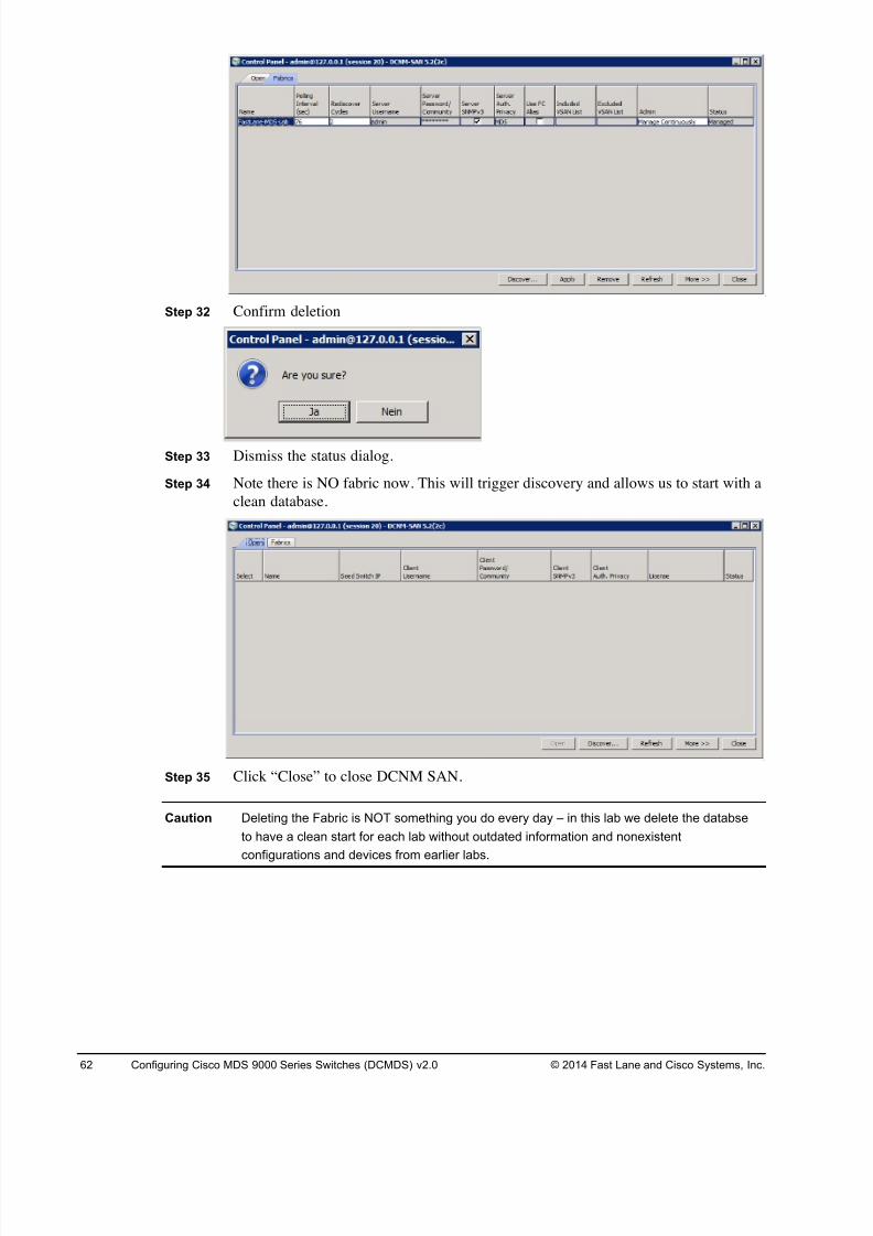
8/18/2019 FL_DCMDS_2.0.3_LG(1).pdf
http://slidepdf.com/reader/full/fldcmds203lg1pdf 62/482
62 Configuring Cisco MDS 9000 Series Switches (DCMDS) v2.0 © 2014 Fast Lane and Cisco Systems, Inc.
Step 32 Confirm deletion
Step 33 Dismiss the status dialog.
Step 34 Note there is NO fabric now. This will trigger discovery and allows us to start with a
clean database.
Step 35 Click “Close” to close DCNM SAN.
Caution Deleting the Fabric is NOT something you do every day – in this lab we delete the databse
to have a clean start for each lab without outdated information and nonexistent
configurations and devices from earlier labs.
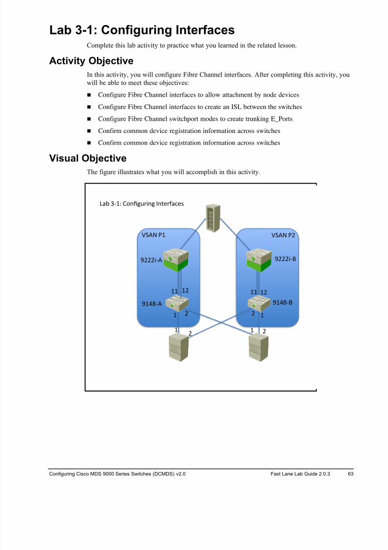
8/18/2019 FL_DCMDS_2.0.3_LG(1).pdf
http://slidepdf.com/reader/full/fldcmds203lg1pdf 63/482
Configuring Cisco MDS 9000 Series Switches (DCMDS) v2.0 Fast Lane Lab Guide 2.0.3 63
Lab 3-1: Configuring Interfaces Complete this lab activity to practice what you learned in the related lesson.
Activity Objective
In this activity, you will configure Fibre Channel interfaces. After completing this activity, you
will be able to meet these objectives:
! Configure Fibre Channel interfaces to allow attachment by node devices
! Configure Fibre Channel interfaces to create an ISL between the switches
! Configure Fibre Channel switchport modes to create trunking E_Ports
! Confirm common device registration information across switches
! Confirm common device registration information across switches
Visual Objective
The figure illustrates what you will accomplish in this activity.
! !# #
!# !! !#!!
!# #!
$!%&'( $!%&')
$###*'( $###*')
+,- .'!/ 0123456*24 72896:,;9<
=>(? @! =>(? @#
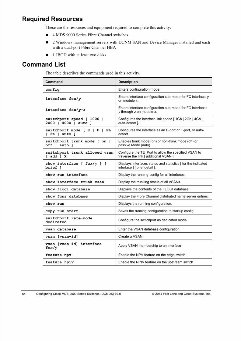
8/18/2019 FL_DCMDS_2.0.3_LG(1).pdf
http://slidepdf.com/reader/full/fldcmds203lg1pdf 64/482
64 Configuring Cisco MDS 9000 Series Switches (DCMDS) v2.0 © 2014 Fast Lane and Cisco Systems, Inc.
Required Resources
These are the resources and equipment required to complete this activity:
! 4 MDS 9000 Series Fibre Channel switches
! 2 Windows management servers with DCNM SAN and Device Manager installed and each
with a dual-port Fibre Channel HBA
! 1 JBOD with at least two disks
Command List
The table describes the commands used in this activity.
Command Description
config Enters configuration mode.
interface fcx / y Enters interface configuration sub-mode for FC interface y on module x .
interface fcx / y-z Enters interface configuration sub-mode for FC interfacesy through z on module x .
switchport speed [ 1000 |2000 | 4000 | auto ]
Configures the interface link speed [ 1Gb | 2Gb | 4Gb |auto-detect ].
switchport mode [ E | F | FL| FX | auto ]
Configures the interface as an E-port or F-port, or auto-detect.
switchport trunk mode [ on |off | auto ]
Enables trunk mode (on) or non-trunk mode (off) orpassive Mode (auto)
switchport trunk allowed vsan[ add ] X
Configure the TE_Port to allow the specified VSAN totraverse the link [ additional VSAN ].
show interface [ fcx / y ] [ brief ]
Displays interfaces status and statistics [ for the indicatedinterface ] [ brief detail ].
show run interface Display the running-config for all interfaces.
show interface trunk vsan Display the trunking status of all VSANs.
show flogi database Displays the contents of the FLOGI database.
show fcns database Display the Fibre Channel distributed name server entries.
show run Displays the running configuration.
copy run start Saves the running configuration to startup config.
switchport rate-modededicated
Configure the switchport as dedicated mode
vsan database Enter the VSAN database configuration
vsan [vsan-id] Create a VSAN
vsan [vsan-id] interfacefcx/y
Apply VSAN membership to an interface
feature npv Enable the NPV feature on the edge switch
feature npiv Enable the NPIV feature on the upstream switch
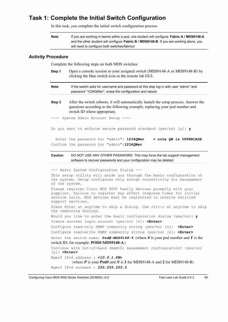
8/18/2019 FL_DCMDS_2.0.3_LG(1).pdf
http://slidepdf.com/reader/full/fldcmds203lg1pdf 65/482
Configuring Cisco MDS 9000 Series Switches (DCMDS) v2.0 Fast Lane Lab Guide 2.0.3 65
Task 1: Complete the Initial Switch Configuration
In this task, you complete the initial switch configuration process.
Note If you are working in teams within a pod, one student will configure Fabric A / MDS9148-A
and the other student will configure Fabric B / MDS9148-B. If you are working alone, you
will need to configure both switches/fabrics!
Activity Procedure
Complete the following steps on both MDS switches:
Step 1 Open a console session to your assigned switch (MDS9148-A or MDS9148-B) by
clicking the blue switch icon in the remote lab GUI.
Note If the switch asks for username and password at this step log in with user “admin” and
password “1234QWer”, erase the configuration and reboot.
Step 2 After the switch reboots, it will automatically launch the setup process. Answer the
questions according to the following example, replacing your pod number and
switch ID where appropriate.---- System Admin Account Setup ----
Do you want to enforce secure password standard (yes/no) [y]: y
Enter the password for "admin": 1234QWer < note QW is UPPERCASE
Confirm the password for "admin":1234QWer
Caution DO NOT USE ANY OTHER PASSWORD. This may force the lab support management
software to recover passwords and your configuration may be deleted.
--- Basic System Configuration Dialog ---
This setup utility will guide you through the basic configuration ofthe system. Setup configures only enough connectivity for managementof the system.
Please register Cisco MDS 9000 Family devices promptly with yoursupplier. Failure to register may affect response times for initialservice calls. MDS devices must be registered to receive entitledsupport services.
Press Enter at anytime to skip a dialog. Use ctrl-c at anytime to skipthe remaining dialogs.
Would you like to enter the basic configuration dialog (yes/no): y
Create another login account (yes/no) [n]: <Enter>
Configure read-only SNMP community string (yes/no) [n]: <Enter>
Configure read-write SNMP community string (yes/no) [n]: <Enter>
Enter the switch name: Pod#-MDS9148-Y (where # is your pod number and Y is the
switch ID; for example: POD#-MDS9148-A)
Continue with Out-of-band (mgmt0) management configuration? (yes/no)[y]: <Enter>
Mgmt0 IPv4 address : <10.0.1.PN >
(where P is your Pod# and N is 1 for MDS9148-A and 2 for MDS9148-B)
Mgmt0 IPv4 netmask : 255.255.255.0
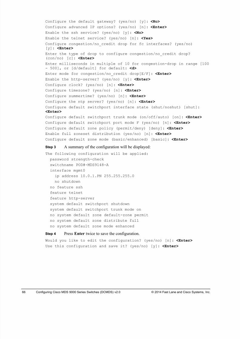
8/18/2019 FL_DCMDS_2.0.3_LG(1).pdf
http://slidepdf.com/reader/full/fldcmds203lg1pdf 66/482
66 Configuring Cisco MDS 9000 Series Switches (DCMDS) v2.0 © 2014 Fast Lane and Cisco Systems, Inc.
Configure the default gateway? (yes/no) [y]: <No>
Configure advanced IP options? (yes/no) [n]: <Enter>
Enable the ssh service? (yes/no) [y]: <No>
Enable the telnet service? (yes/no) [n]: <Yes>
Configure congestion/no_credit drop for fc interfaces? (yes/no)[y]: <Enter>
Enter the type of drop to configure congestion/no_credit drop?
(con/no) [c]: <Enter>Enter milliseconds in multiple of 10 for congestion-drop in range [100- 500], or [d/default] for default: <d>
Enter mode for congestion/no_credit drop[E/F]: <Enter>
Enable the http-server? (yes/no) [y]: <Enter>
Configure clock? (yes/no) [n]: <Enter>
Configure timezone? (yes/no) [n]: <Enter>
Configure summertime? (yes/no) [n]: <Enter>
Configure the ntp server? (yes/no) [n]: <Enter>
Configure default switchport interface state (shut/noshut) [shut]: <Enter>
Configure default switchport trunk mode (on/off/auto) [on]: <Enter> Configure default switchport port mode F (yes/no) [n]: <Enter>
Configure default zone policy (permit/deny) [deny]: <Enter>
Enable full zoneset distribution (yes/no) [n]: <Enter>
Configure default zone mode (basic/enhanced) [basic]: <Enter>
Step 3 A summary of the configuration will be displayed:
The following configuration will be applied:
password strength-check
switchname POD#-MDS9148-A
interface mgmt0
ip address 10.0.1.PN 255.255.255.0
no shutdown
no feature ssh
feature telnet
feature http-server
system default switchport shutdown
system default switchport trunk mode on
no system default zone default-zone permit
no system default zone distribute full
no system default zone mode enhanced
Step 4 Press Enter twice to save the configuration.
Would you like to edit the configuration? (yes/no) [n]: <Enter>
Use this configuration and save it? (yes/no) [y]: <Enter>
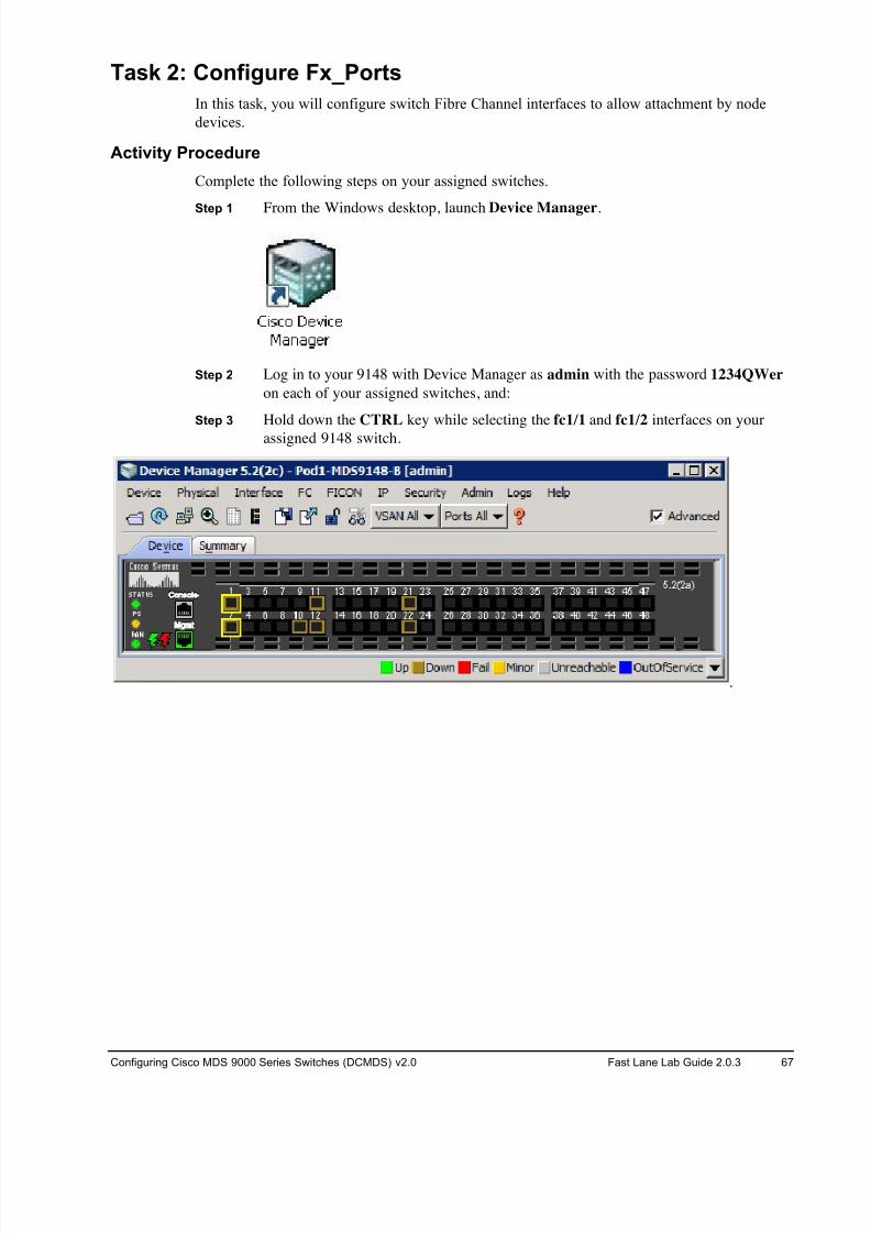
8/18/2019 FL_DCMDS_2.0.3_LG(1).pdf
http://slidepdf.com/reader/full/fldcmds203lg1pdf 67/482
Configuring Cisco MDS 9000 Series Switches (DCMDS) v2.0 Fast Lane Lab Guide 2.0.3 67
Task 2: Configure Fx_Ports
In this task, you will configure switch Fibre Channel interfaces to allow attachment by node
devices.
Activity Procedure
Complete the following steps on your assigned switches.
Step 1 From the Windows desktop, launch Device Manager.
Step 2 Log in to your 9148 with Device Manager as admin with the password 1234QWer
on each of your assigned switches, and:
Step 3 Hold down the CTRL key while selecting the fc1/1 and fc1/2 interfaces on your
assigned 9148 switch.
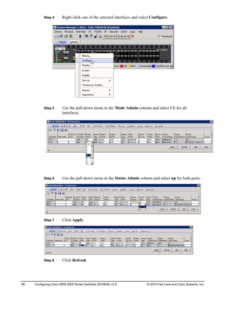
8/18/2019 FL_DCMDS_2.0.3_LG(1).pdf
http://slidepdf.com/reader/full/fldcmds203lg1pdf 68/482
68 Configuring Cisco MDS 9000 Series Switches (DCMDS) v2.0 © 2014 Fast Lane and Cisco Systems, Inc.
Step 4 Right-click one of the selected interfaces and select Configure.
Step 5 Use the pull-down menu in the Mode Admin column and select FX for all
interfaces.
Step 6 Use the pull-down menu in the Status Admin column and select up for both ports.
Step 7 Click Apply.
Step 8 Click Refresh.

8/18/2019 FL_DCMDS_2.0.3_LG(1).pdf
http://slidepdf.com/reader/full/fldcmds203lg1pdf 69/482
Configuring Cisco MDS 9000 Series Switches (DCMDS) v2.0 Fast Lane Lab Guide 2.0.3 69
Step 9 Compare the Mode Admin and Mode Oper columns to confirm that FX ports will
automatically detect N_Port (hosts) and they would also support NL_Port (loop /
JBOD) attached devices.
Step 10 Close the FC Interfaces configuration window.
Step 11 Notice that the operational port topology types in Device Manager Device view has
changed, but it always display the port state (F), NOT the port mode (FX).
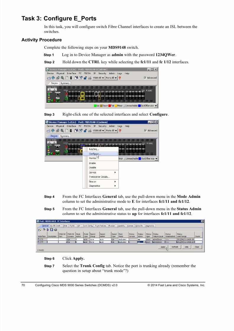
8/18/2019 FL_DCMDS_2.0.3_LG(1).pdf
http://slidepdf.com/reader/full/fldcmds203lg1pdf 70/482
70 Configuring Cisco MDS 9000 Series Switches (DCMDS) v2.0 © 2014 Fast Lane and Cisco Systems, Inc.
Task 3: Configure E_Ports
In this task, you will configure switch Fibre Channel interfaces to create an ISL between the
switches.
Activity Procedure
Complete the following steps on your MDS9148 switch.
Step 1 Log in to Device Manager as admin with the password 1234QWer.
Step 2 Hold down the CTRL key while selecting the fc1/11 and fc 1/12 interfaces.
Step 3 Right-click one of the selected interfaces and select Configure.
Step 4 From the FC Interfaces General tab, use the pull-down menu in the Mode Admin
column to set the administrative mode to E for interfaces fc1/11 and fc1/12.
Step 5 From the FC Interfaces General tab, use the pull-down menu in the Status Admin
column to set the administrative status to up for interfaces fc1/11 and fc1/12.
Step 6 Click Apply.
Step 7 Select the Trunk Config tab. Notice the port is trunking already (remember the
question in setup about “trunk mode”?)
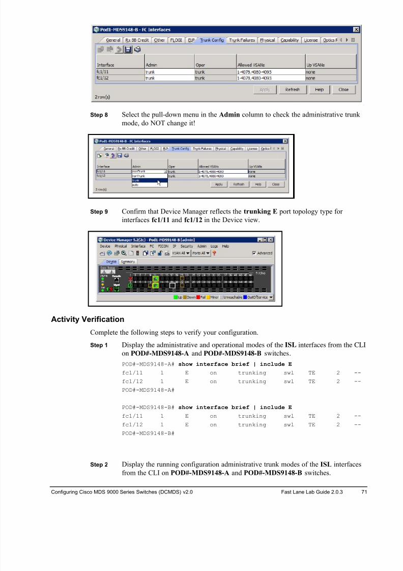
8/18/2019 FL_DCMDS_2.0.3_LG(1).pdf
http://slidepdf.com/reader/full/fldcmds203lg1pdf 71/482
Configuring Cisco MDS 9000 Series Switches (DCMDS) v2.0 Fast Lane Lab Guide 2.0.3 71
Step 8 Select the pull-down menu in the Admin column to check the administrative trunk
mode, do NOT change it!
Step 9 Confirm that Device Manager reflects the trunking E port topology type for
interfaces fc1/11 and fc1/12 in the Device view.
Activity Verification
Complete the following steps to verify your configuration.
Step 1 Display the administrative and operational modes of the ISL interfaces from the CLI
on POD#-MDS9148-A and POD#-MDS9148-B switches.
POD#-MDS9148-A# show interface brief | include E
fc1/11 1 E on trunking swl TE 2 --
fc1/12 1 E on trunking swl TE 2 --
POD#-MDS9148-A#
POD#-MDS9148-B# show interface brief | include E
fc1/11 1 E on trunking swl TE 2 --
fc1/12 1 E on trunking swl TE 2 --
POD#-MDS9148-B#
Step 2 Display the running configuration administrative trunk modes of the ISL interfaces
from the CLI on POD#-MDS9148-A and POD#-MDS9148-B switches.
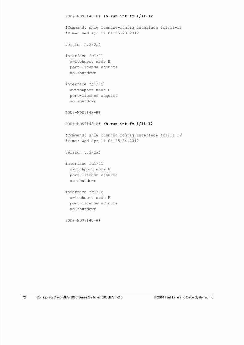
8/18/2019 FL_DCMDS_2.0.3_LG(1).pdf
http://slidepdf.com/reader/full/fldcmds203lg1pdf 72/482
72 Configuring Cisco MDS 9000 Series Switches (DCMDS) v2.0 © 2014 Fast Lane and Cisco Systems, Inc.
POD#-MDS9148-B# sh run int fc 1/11-12
!Command: show running-config interface fc1/11-12
!Time: Wed Apr 11 04:25:20 2012
version 5.2(2a)
interface fc1/11
switchport mode E
port-license acquire
no shutdown
interface fc1/12
switchport mode E
port-license acquire
no shutdown
POD#-MDS9148-B#
POD#-MDS9148-A# sh run int fc 1/11-12
!Command: show running-config interface fc1/11-12
!Time: Wed Apr 11 04:25:34 2012
version 5.2(2a)
interface fc1/11
switchport mode E
port-license acquire
no shutdown
interface fc1/12
switchport mode E
port-license acquire
no shutdown
POD#-MDS9148-A#
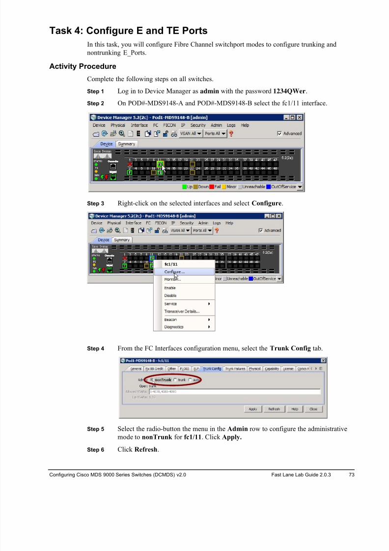
8/18/2019 FL_DCMDS_2.0.3_LG(1).pdf
http://slidepdf.com/reader/full/fldcmds203lg1pdf 73/482
Configuring Cisco MDS 9000 Series Switches (DCMDS) v2.0 Fast Lane Lab Guide 2.0.3 73
Task 4: Configure E and TE Ports
In this task, you will configure Fibre Channel switchport modes to configure trunking and
nontrunking E_Ports.
Activity Procedure
Complete the following steps on all switches.
Step 1 Log in to Device Manager as admin with the password 1234QWer.
Step 2 On POD#-MDS9148-A and POD#-MDS9148-B select the fc1/11 interface.
Step 3 Right-click on the selected interfaces and select Configure.
Step 4 From the FC Interfaces configuration menu, select the Trunk Config tab.
Step 5 Select the radio-button the menu in the Admin row to configure the administrative
mode to nonTrunk for fc1/11. Click Apply.
Step 6 Click Refresh.
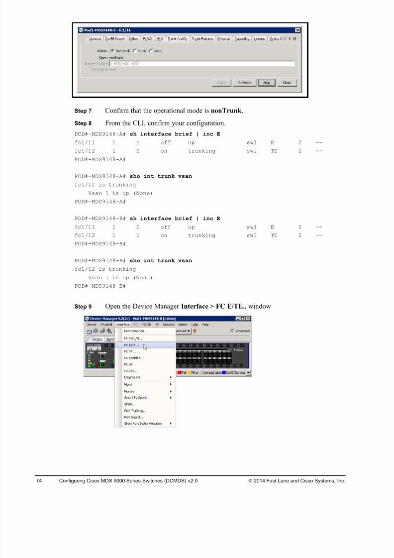
8/18/2019 FL_DCMDS_2.0.3_LG(1).pdf
http://slidepdf.com/reader/full/fldcmds203lg1pdf 74/482
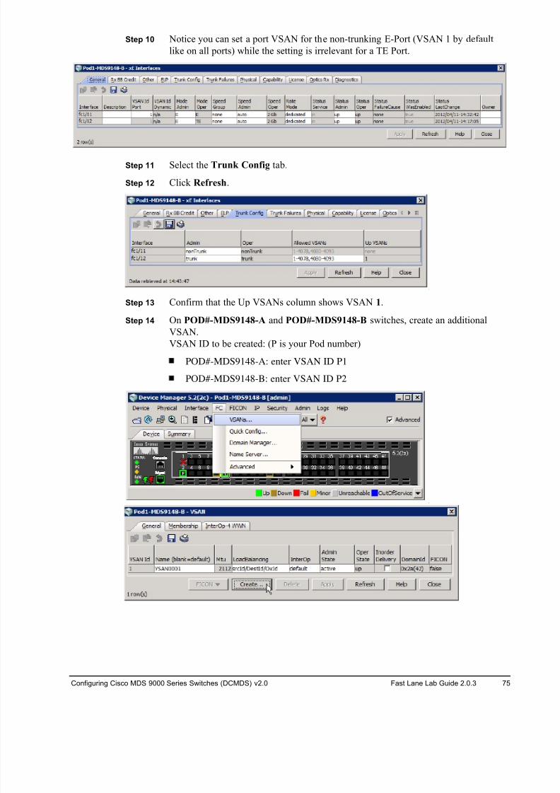
8/18/2019 FL_DCMDS_2.0.3_LG(1).pdf
http://slidepdf.com/reader/full/fldcmds203lg1pdf 75/482
Configuring Cisco MDS 9000 Series Switches (DCMDS) v2.0 Fast Lane Lab Guide 2.0.3 75
Step 10 Notice you can set a port VSAN for the non-trunking E-Port (VSAN 1 by default
like on all ports) while the setting is irrelevant for a TE Port.
Step 11 Select the Trunk Config tab.
Step 12 Click Refresh.
Step 13 Confirm that the Up VSANs column shows VSAN 1.
Step 14 On POD#-MDS9148-A and POD#-MDS9148-B switches, create an additional
VSAN.
VSAN ID to be created: (P is your Pod number)
POD#-MDS9148-A: enter VSAN ID P1
POD#-MDS9148-B: enter VSAN ID P2
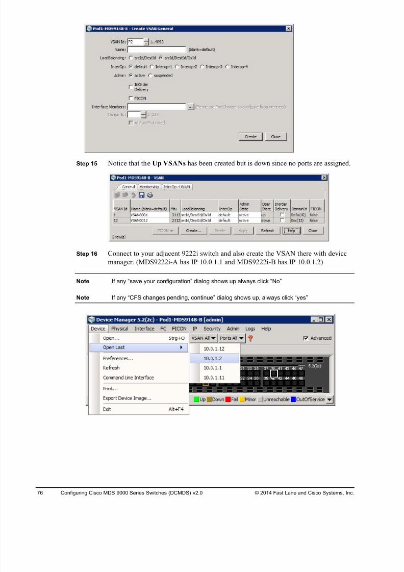
8/18/2019 FL_DCMDS_2.0.3_LG(1).pdf
http://slidepdf.com/reader/full/fldcmds203lg1pdf 76/482
76 Configuring Cisco MDS 9000 Series Switches (DCMDS) v2.0 © 2014 Fast Lane and Cisco Systems, Inc.
Step 15 Notice that the Up VSANs has been created but is down since no ports are assigned.
Step 16 Connect to your adjacent 9222i switch and also create the VSAN there with device
manager. (MDS9222i-A has IP 10.0.1.1 and MDS9222i-B has IP 10.0.1.2)
Note If any “save your configuration” dialog shows up always click “No”
Note If any “CFS changes pending, continue” dialog shows up, always click “yes”
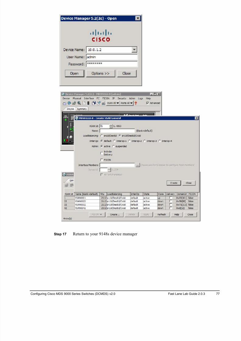
8/18/2019 FL_DCMDS_2.0.3_LG(1).pdf
http://slidepdf.com/reader/full/fldcmds203lg1pdf 77/482
Configuring Cisco MDS 9000 Series Switches (DCMDS) v2.0 Fast Lane Lab Guide 2.0.3 77
Step 17 Return to your 9148s device manager
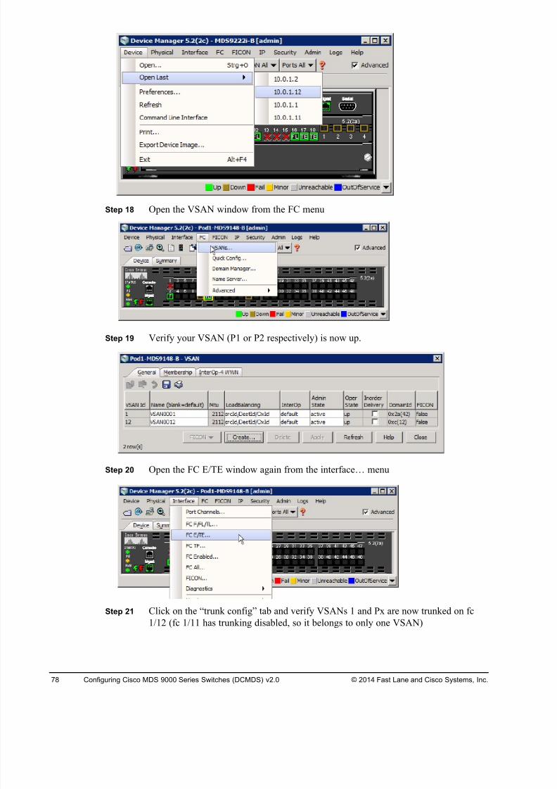
8/18/2019 FL_DCMDS_2.0.3_LG(1).pdf
http://slidepdf.com/reader/full/fldcmds203lg1pdf 78/482
78 Configuring Cisco MDS 9000 Series Switches (DCMDS) v2.0 © 2014 Fast Lane and Cisco Systems, Inc.
Step 18 Open the VSAN window from the FC menu
Step 19 Verify your VSAN (P1 or P2 respectively) is now up.
Step 20 Open the FC E/TE window again from the interface… menu
Step 21 Click on the “trunk config” tab and verify VSANs 1 and Px are now trunked on fc
1/12 (fc 1/11 has trunking disabled, so it belongs to only one VSAN)
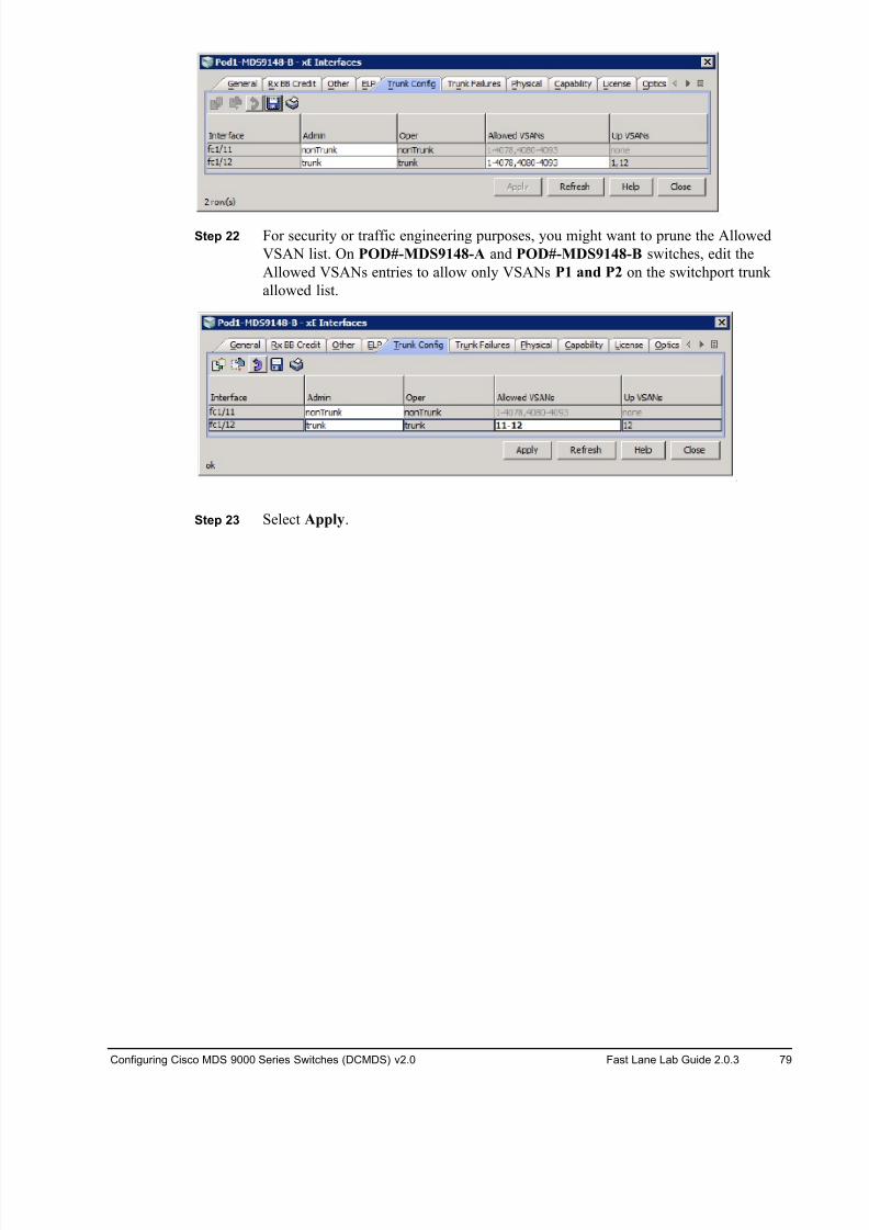
8/18/2019 FL_DCMDS_2.0.3_LG(1).pdf
http://slidepdf.com/reader/full/fldcmds203lg1pdf 79/482
Configuring Cisco MDS 9000 Series Switches (DCMDS) v2.0 Fast Lane Lab Guide 2.0.3 79
Step 22 For security or traffic engineering purposes, you might want to prune the Allowed
VSAN list. On POD#-MDS9148-A and POD#-MDS9148-B switches, edit the
Allowed VSANs entries to allow only VSANs P1 and P2 on the switchport trunk
allowed list.
Step 23 Select Apply.
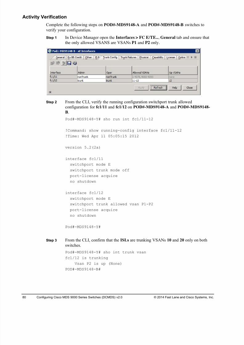
8/18/2019 FL_DCMDS_2.0.3_LG(1).pdf
http://slidepdf.com/reader/full/fldcmds203lg1pdf 80/482
80 Configuring Cisco MDS 9000 Series Switches (DCMDS) v2.0 © 2014 Fast Lane and Cisco Systems, Inc.
Activity Verification
Complete the following steps on POD#-MDS9148-A and POD#-MDS9148-B switches to
verify your configuration.
Step 1 In Device Manager open the Interfaces > FC E/TE.., General tab and ensure that
the only allowed VSANS are VSANs P1 and P2 only.
Step 2 From the CLI, verify the running configuration switchport trunk allowed
configuration for fc1/11 and fc1/12 on POD#-MDS9148-A and POD#-MDS9148-
B.
Pod#-MDS9148-Y# sho run int fc1/11-12
!Command: show running-config interface fc1/11-12
!Time: Wed Apr 11 05:05:15 2012
version 5.2(2a)
interface fc1/11
switchport mode E
switchport trunk mode off
port-license acquire
no shutdown
interface fc1/12
switchport mode E
switchport trunk allowed vsan P1-P2
port-license acquire
no shutdown
Pod#-MDS9148-Y#
Step 3 From the CLI, confirm that the ISLs are trunking VSANs 10 and 20 only on bothswitches.
Pod#-MDS9148-Y# sho int trunk vsan
fc1/12 is trunking
Vsan P2 is up (None)
POD#-MDS9148-B#
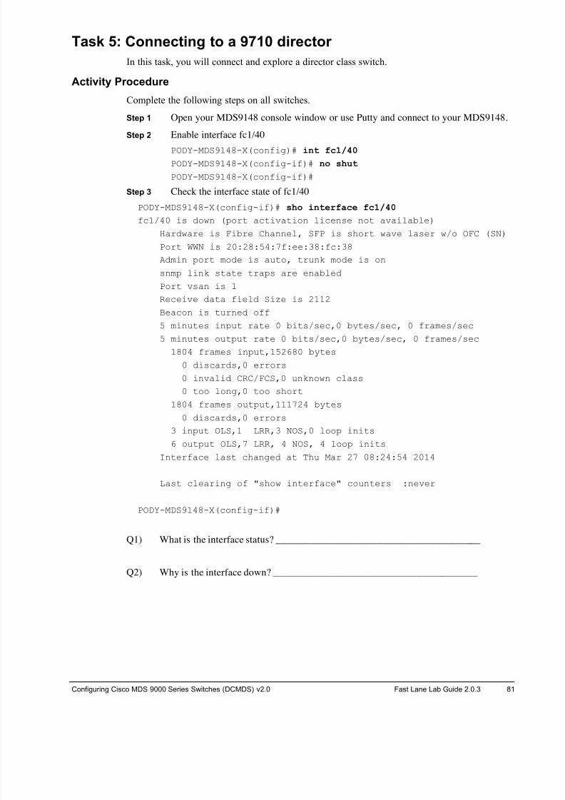
8/18/2019 FL_DCMDS_2.0.3_LG(1).pdf
http://slidepdf.com/reader/full/fldcmds203lg1pdf 81/482
Configuring Cisco MDS 9000 Series Switches (DCMDS) v2.0 Fast Lane Lab Guide 2.0.3 81
Task 5: Connecting to a 9710 director
In this task, you will connect and explore a director class switch.
Activity Procedure
Complete the following steps on all switches.
Step 1 Open your MDS9148 console window or use Putty and connect to your MDS9148.
Step 2 Enable interface fc1/40
PODY-MDS9148-X(config)# int fc1/40
PODY-MDS9148-X(config-if)# no shut
PODY-MDS9148-X(config-if)#
Step 3 Check the interface state of fc1/40
PODY-MDS9148-X(config-if)# sho interface fc1/40
fc1/40 is down (port activation license not available)
Hardware is Fibre Channel, SFP is short wave laser w/o OFC (SN)
Port WWN is 20:28:54:7f:ee:38:fc:38
Admin port mode is auto, trunk mode is on
snmp link state traps are enabled
Port vsan is 1
Receive data field Size is 2112
Beacon is turned off
5 minutes input rate 0 bits/sec,0 bytes/sec, 0 frames/sec
5 minutes output rate 0 bits/sec,0 bytes/sec, 0 frames/sec
1804 frames input,152680 bytes
0 discards,0 errors
0 invalid CRC/FCS,0 unknown class
0 too long,0 too short
1804 frames output,111724 bytes
0 discards,0 errors3 input OLS,1 LRR,3 NOS,0 loop inits
6 output OLS,7 LRR, 4 NOS, 4 loop inits
Interface last changed at Thu Mar 27 08:24:54 2014
Last clearing of "show interface" counters :never
PODY-MDS9148-X(config-if)#
Q1) What is the interface status? ________________________________________
Q2) Why is the interface down? ________________________________________
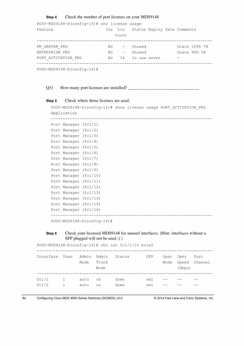
8/18/2019 FL_DCMDS_2.0.3_LG(1).pdf
http://slidepdf.com/reader/full/fldcmds203lg1pdf 82/482
82 Configuring Cisco MDS 9000 Series Switches (DCMDS) v2.0 © 2014 Fast Lane and Cisco Systems, Inc.
Step 4 Check the number of port licenses on your MDS9148
PODY-MDS9148-X(config-if)# sho license usage
Feature Ins Lic Status Expiry Date Comments
Count
--------------------------------------------------------------------------
FM_SERVER_PKG No - Unused Grace 109D 7H
ENTERPRISE_PKG No - Unused Grace 96D 5H
PORT_ACTIVATION_PKG No 16 In use never -
--------------------------------------------------------------------------
PODY-MDS9148-X(config-if)#
Q3) How many port licenses are installed? ________________________________
Step 5 Check where those licenses are used.
PODY-MDS9148-X(config-if)# show license usage PORT_ACTIVATION_PKG
Application
--------------------------------------------------------------------
Port Manager (fc1/1)
Port Manager (fc1/2)
Port Manager (fc1/3)
Port Manager (fc1/4)
Port Manager (fc1/5)
Port Manager (fc1/6)
Port Manager (fc1/7)
Port Manager (fc1/8)
Port Manager (fc1/9)
Port Manager (fc1/10)
Port Manager (fc1/11)Port Manager (fc1/12)
Port Manager (fc1/13)
Port Manager (fc1/14)
Port Manager (fc1/15)
Port Manager (fc1/16)
--------------------------------------------------------------------
PODY-MDS9148-X(config-if)#
Step 6 Check your licensed MDS9148 for unused interfaces. (Hint: interfaces without a
SFP plugged will not be used ;) )
PODY-MDS9148-X(config-if)# sho int fc1/1-16 brief
--------------------------------------------------------------------------
Interface Vsan Admin Admin Status SFP Oper Oper Port
Mode Trunk Mode Speed Channel
Mode (Gbps)
--------------------------------------------------------------------------
fc1/1 1 auto on down swl -- -- --
fc1/2 1 auto on down swl -- -- --
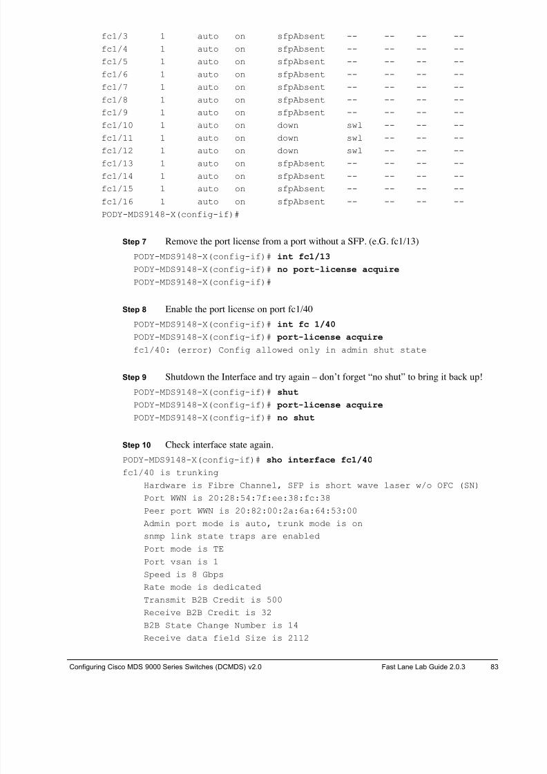
8/18/2019 FL_DCMDS_2.0.3_LG(1).pdf
http://slidepdf.com/reader/full/fldcmds203lg1pdf 83/482
Configuring Cisco MDS 9000 Series Switches (DCMDS) v2.0 Fast Lane Lab Guide 2.0.3 83
fc1/3 1 auto on sfpAbsent -- -- -- --
fc1/4 1 auto on sfpAbsent -- -- -- --
fc1/5 1 auto on sfpAbsent -- -- -- --
fc1/6 1 auto on sfpAbsent -- -- -- --
fc1/7 1 auto on sfpAbsent -- -- -- --
fc1/8 1 auto on sfpAbsent -- -- -- --
fc1/9 1 auto on sfpAbsent -- -- -- --
fc1/10 1 auto on down swl -- -- --
fc1/11 1 auto on down swl -- -- --
fc1/12 1 auto on down swl -- -- --
fc1/13 1 auto on sfpAbsent -- -- -- --
fc1/14 1 auto on sfpAbsent -- -- -- --
fc1/15 1 auto on sfpAbsent -- -- -- --
fc1/16 1 auto on sfpAbsent -- -- -- --
PODY-MDS9148-X(config-if)#
Step 7 Remove the port license from a port without a SFP. (e.G. fc1/13)
PODY-MDS9148-X(config-if)# int fc1/13
PODY-MDS9148-X(config-if)# no port-license acquirePODY-MDS9148-X(config-if)#
Step 8 Enable the port license on port fc1/40
PODY-MDS9148-X(config-if)# int fc 1/40
PODY-MDS9148-X(config-if)# port-license acquire
fc1/40: (error) Config allowed only in admin shut state
Step 9 Shutdown the Interface and try again – don’t forget “no shut” to bring it back up!
PODY-MDS9148-X(config-if)# shut
PODY-MDS9148-X(config-if)# port-license acquirePODY-MDS9148-X(config-if)# no shut
Step 10 Check interface state again.
PODY-MDS9148-X(config-if)# sho interface fc1/40
fc1/40 is trunking
Hardware is Fibre Channel, SFP is short wave laser w/o OFC (SN)
Port WWN is 20:28:54:7f:ee:38:fc:38
Peer port WWN is 20:82:00:2a:6a:64:53:00
Admin port mode is auto, trunk mode is on
snmp link state traps are enabled
Port mode is TE
Port vsan is 1
Speed is 8 Gbps
Rate mode is dedicated
Transmit B2B Credit is 500
Receive B2B Credit is 32
B2B State Change Number is 14
Receive data field Size is 2112
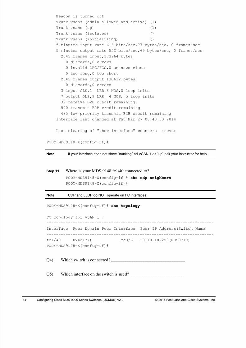
8/18/2019 FL_DCMDS_2.0.3_LG(1).pdf
http://slidepdf.com/reader/full/fldcmds203lg1pdf 84/482
84 Configuring Cisco MDS 9000 Series Switches (DCMDS) v2.0 © 2014 Fast Lane and Cisco Systems, Inc.
Beacon is turned off
Trunk vsans (admin allowed and active) (1)
Trunk vsans (up) (1)
Trunk vsans (isolated) ()
Trunk vsans (initializing) ()
5 minutes input rate 616 bits/sec,77 bytes/sec, 0 frames/sec
5 minutes output rate 552 bits/sec,69 bytes/sec, 0 frames/sec
2045 frames input,173964 bytes
0 discards,0 errors
0 invalid CRC/FCS,0 unknown class
0 too long,0 too short
2045 frames output,130612 bytes
0 discards,0 errors
3 input OLS,1 LRR,3 NOS,0 loop inits
7 output OLS,9 LRR, 4 NOS, 5 loop inits
32 receive B2B credit remaining
500 transmit B2B credit remaining
485 low priority transmit B2B credit remaining
Interface last changed at Thu Mar 27 08:43:33 2014
Last clearing of "show interface" counters :never
PODY-MDS9148-X(config-if)#
Note If your interface does not show “trunking” ad VSAN 1 as “up” ask your instructor for help.
Step 11 Where is your MDS 9148 fc1/40 connected to?
PODY-MDS9148-X(config-if)# sho cdp neighbors
PODY-MDS9148-X(config-if)#
Note CDP and LLDP do NOT operate on FC interfaces.
PODY-MDS9148-X(config-if)# sho topology
FC Topology for VSAN 1 :
----------------------------------------------------------------------
Interface Peer Domain Peer Interface Peer IP Address(Switch Name)
----------------------------------------------------------------------
fc1/40 0x4d(77) fc3/Z 10.10.10.250(MDS9710)
PODY-MDS9148-X(config-if)#
Q4) Which switch is connected? _________________________________
Q5) Which interface on the switch is used? ________________________
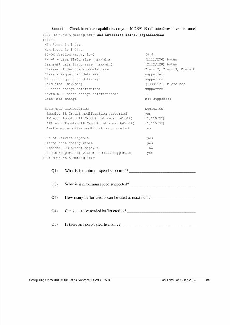
8/18/2019 FL_DCMDS_2.0.3_LG(1).pdf
http://slidepdf.com/reader/full/fldcmds203lg1pdf 85/482
Configuring Cisco MDS 9000 Series Switches (DCMDS) v2.0 Fast Lane Lab Guide 2.0.3 85
Step 12 Check interface capabilities on your MDS9148 (all interfaces have the same)
PODY-MDS9148-X(config-if)# sho interface fc1/40 capabilities
fc1/40
Min Speed is 1 Gbps
Max Speed is 8 Gbps
FC-PH Version (high, low) (0,6)
Receive data field size (max/min) (2112/256) bytes
Transmit data field size (max/min) (2112/128) bytes
Classes of Service supported are Class 2, Class 3, Class F
Class 2 sequential delivery supported
Class 3 sequential delivery supported
Hold time (max/min) (100000/1) micro sec
BB state change notification supported
Maximum BB state change notifications 14
Rate Mode change not supported
Rate Mode Capabilities Dedicated
Receive BB Credit modification supported yesFX mode Receive BB Credit (min/max/default) (1/125/32)
ISL mode Receive BB Credit (min/max/default) (2/125/32)
Performance buffer modification supported no
Out of Service capable yes
Beacon mode configurable yes
Extended B2B credit capable no
On demand port activation license supported yes
PODY-MDS9148-X(config-if)#
Q1) What is is minimum speed supported? ________________________________
Q2) What is is maximum speed supported? ________________________________
Q3) How many buffer credits can be used at maximum? _____________________
Q4) Can you use extended buffer credits? _________________________________
Q5) Is there any port-based licensing? ___________________________________
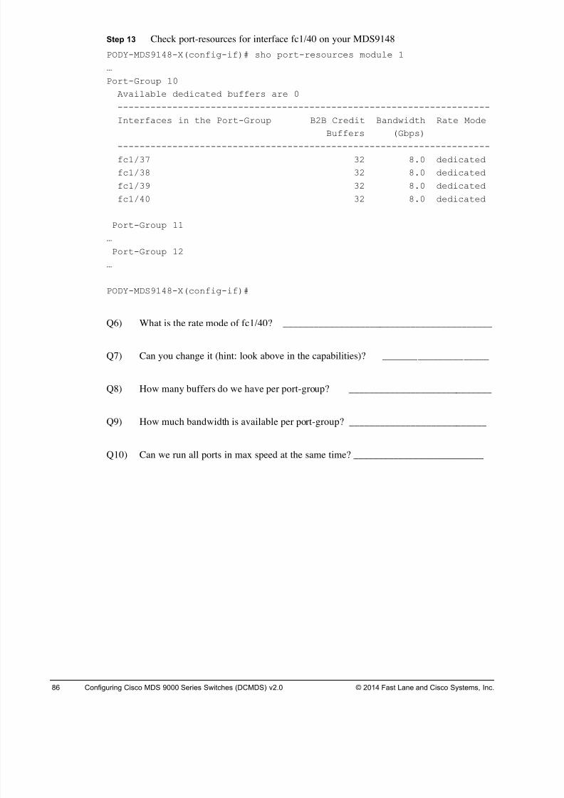
8/18/2019 FL_DCMDS_2.0.3_LG(1).pdf
http://slidepdf.com/reader/full/fldcmds203lg1pdf 86/482
86 Configuring Cisco MDS 9000 Series Switches (DCMDS) v2.0 © 2014 Fast Lane and Cisco Systems, Inc.
Step 13 Check port-resources for interface fc1/40 on your MDS9148
PODY-MDS9148-X(config-if)# sho port-resources module 1
…
Port-Group 10
Available dedicated buffers are 0
--------------------------------------------------------------------
Interfaces in the Port-Group B2B Credit Bandwidth Rate Mode
Buffers (Gbps)
--------------------------------------------------------------------
fc1/37 32 8.0 dedicated
fc1/38 32 8.0 dedicated
fc1/39 32 8.0 dedicated
fc1/40 32 8.0 dedicated
Port-Group 11
…
Port-Group 12
…
PODY-MDS9148-X(config-if)#
Q6) What is the rate mode of fc1/40? _________________________________________
Q7) Can you change it (hint: look above in the capabilities)? _____________________
Q8) How many buffers do we have per port-group? ____________________________
Q9) How much bandwidth is available per port-group? ___________________________
Q10) Can we run all ports in max speed at the same time? __________________________
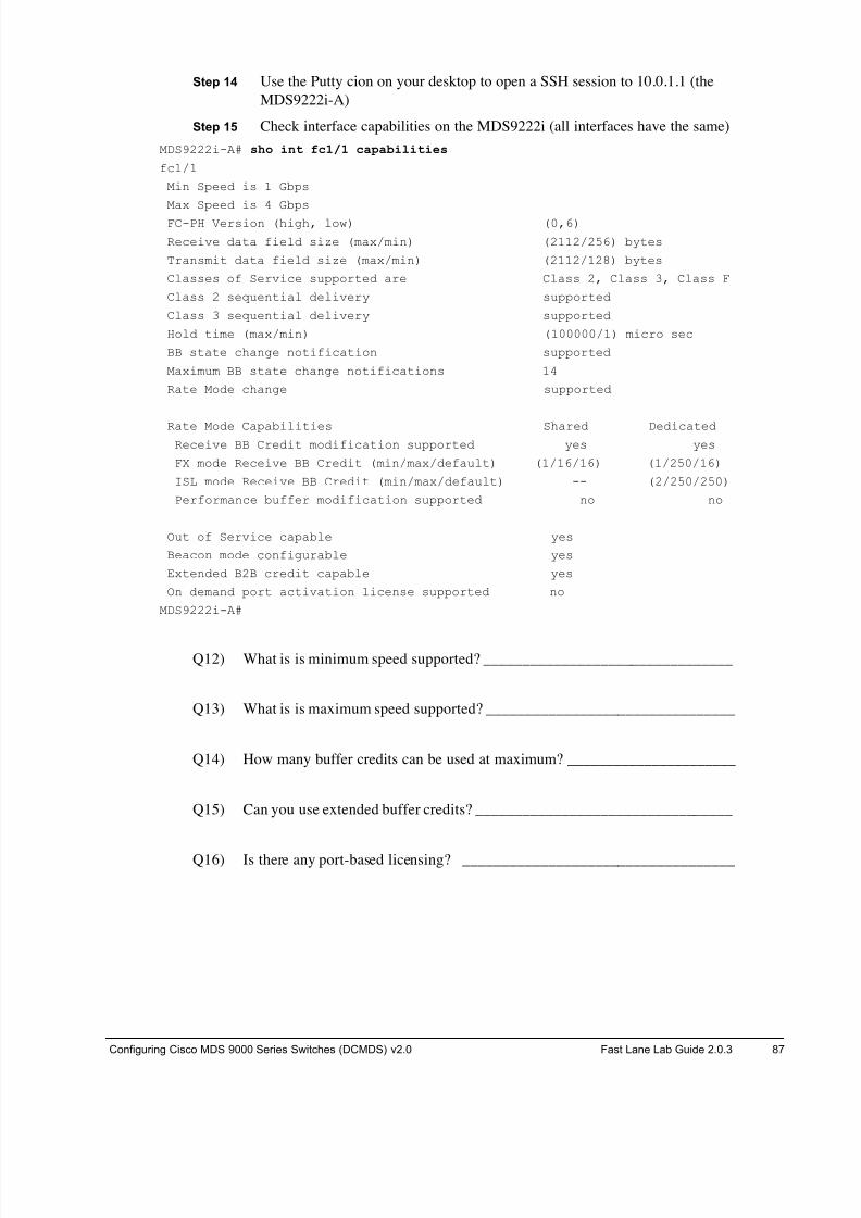
8/18/2019 FL_DCMDS_2.0.3_LG(1).pdf
http://slidepdf.com/reader/full/fldcmds203lg1pdf 87/482
Configuring Cisco MDS 9000 Series Switches (DCMDS) v2.0 Fast Lane Lab Guide 2.0.3 87
Step 14 Use the Putty cion on your desktop to open a SSH session to 10.0.1.1 (the
MDS9222i-A)
Step 15 Check interface capabilities on the MDS9222i (all interfaces have the same)
MDS9222i-A# sho int fc1/1 capabilities
fc1/1
Min Speed is 1 Gbps
Max Speed is 4 Gbps
FC-PH Version (high, low) (0,6)
Receive data field size (max/min) (2112/256) bytes
Transmit data field size (max/min) (2112/128) bytes
Classes of Service supported are Class 2, Class 3, Class F
Class 2 sequential delivery supported
Class 3 sequential delivery supported
Hold time (max/min) (100000/1) micro sec
BB state change notification supported
Maximum BB state change notifications 14
Rate Mode change supported
Rate Mode Capabilities Shared DedicatedReceive BB Credit modification supported yes yes
FX mode Receive BB Credit (min/max/default) (1/16/16) (1/250/16)
ISL mode Receive BB Credit (min/max/default) -- (2/250/250)
Performance buffer modification supported no no
Out of Service capable yes
Beacon mode configurable yes
Extended B2B credit capable yes
On demand port activation license supported no
MDS9222i-A#
Q12) What is is minimum speed supported? ________________________________
Q13) What is is maximum speed supported? ________________________________
Q14) How many buffer credits can be used at maximum? ______________________
Q15) Can you use extended buffer credits? _________________________________
Q16) Is there any port-based licensing? ___________________________________

8/18/2019 FL_DCMDS_2.0.3_LG(1).pdf
http://slidepdf.com/reader/full/fldcmds203lg1pdf 88/482
88 Configuring Cisco MDS 9000 Series Switches (DCMDS) v2.0 © 2014 Fast Lane and Cisco Systems, Inc.
Step 16 Check port-resources for interface fc1/40 on the MDS9222i
MDS9222i-A# sho port-resources module 1
Module 1
Available dedicated buffers are 891
Port-Group 1
Total bandwidth is 12.8 Gbps
Total shared bandwidth is 0.8 Gbps
Allocated dedicated bandwidth is 12.0 Gbps
--------------------------------------------------------------------
Interfaces in the Port-Group B2B Credit Bandwidth Rate Mode
Buffers (Gbps)
--------------------------------------------------------------------
fc1/1 200 2.0 dedicated
fc1/2 200 2.0 dedicated
fc1/3 200 2.0 dedicated
fc1/4 200 2.0 dedicated
fc1/5 200 2.0 dedicated
fc1/6 200 2.0 dedicated
Port-Group 2
…
MDS9222i-A#
Q17) What is the rate mode of fc1/1? ________________________________________
Q18) Can you change it (hint: look above in the capabilities)? _____________________
Q19) How much bandwidth is available per port-group? ___________________________
Q20) Can we run all ports in max speed at the same time? __________________________
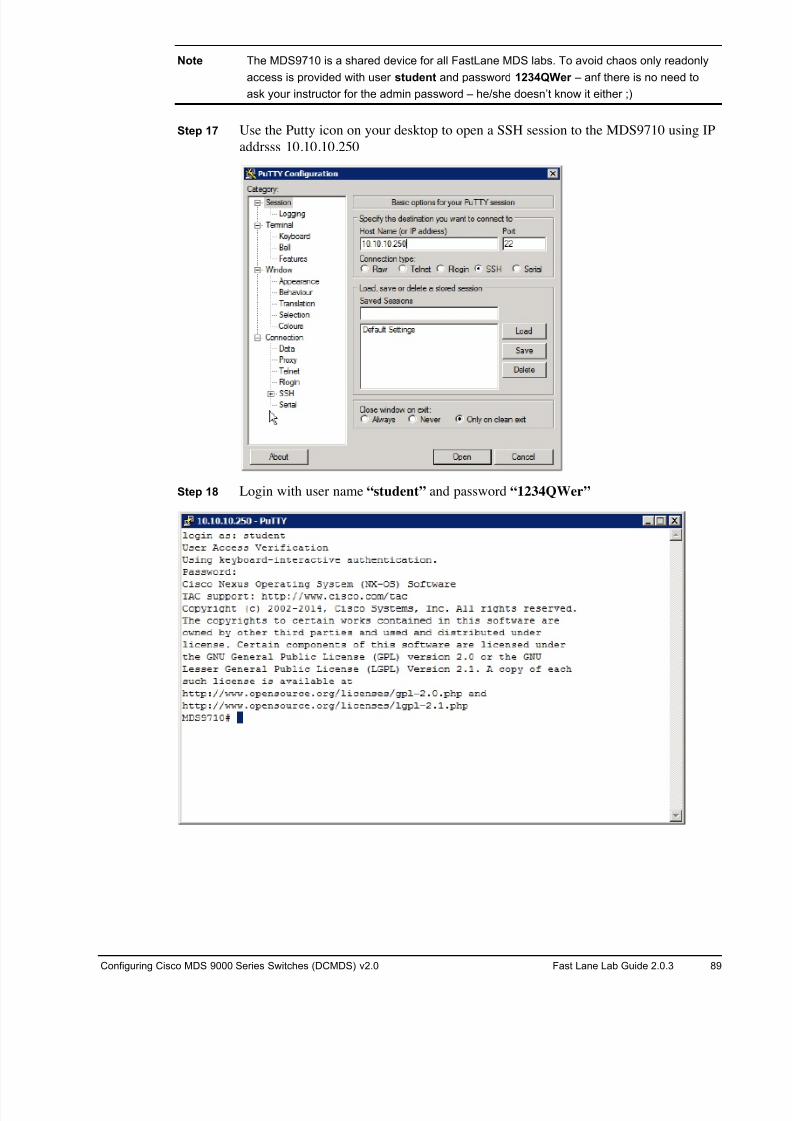
8/18/2019 FL_DCMDS_2.0.3_LG(1).pdf
http://slidepdf.com/reader/full/fldcmds203lg1pdf 89/482
Configuring Cisco MDS 9000 Series Switches (DCMDS) v2.0 Fast Lane Lab Guide 2.0.3 89
Note The MDS9710 is a shared device for all FastLane MDS labs. To avoid chaos only readonly
access is provided with user student and password 1234QWer – anf there is no need to
ask your instructor for the admin password – he/she doesn’t know it either ;)
Step 17 Use the Putty icon on your desktop to open a SSH session to the MDS9710 using IP
addrsss 10.10.10.250
Step 18 Login with user name “student” and password “1234QWer”
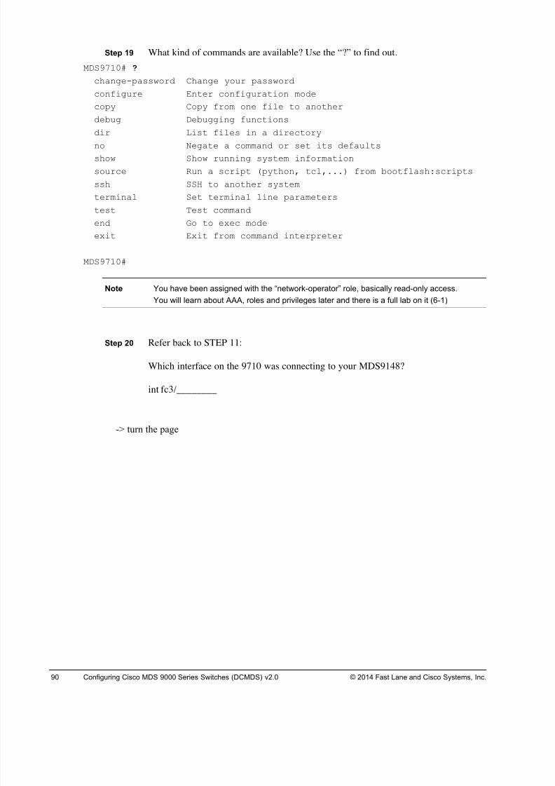
8/18/2019 FL_DCMDS_2.0.3_LG(1).pdf
http://slidepdf.com/reader/full/fldcmds203lg1pdf 90/482
90 Configuring Cisco MDS 9000 Series Switches (DCMDS) v2.0 © 2014 Fast Lane and Cisco Systems, Inc.
Step 19 What kind of commands are available? Use the “?” to find out.
MDS9710# ?
change-password Change your password
configure Enter configuration mode
copy Copy from one file to another
debug Debugging functions
dir List files in a directoryno Negate a command or set its defaults
show Show running system information
source Run a script (python, tcl,...) from bootflash:scripts
ssh SSH to another system
terminal Set terminal line parameters
test Test command
end Go to exec mode
exit Exit from command interpreter
MDS9710#
Note You have been assigned with the “network-operator” role, basically read-only access.
You will learn about AAA, roles and privileges later and there is a full lab on it (6-1)
Step 20 Refer back to STEP 11:
Which interface on the 9710 was connecting to your MDS9148?
int fc3/________
-> turn the page
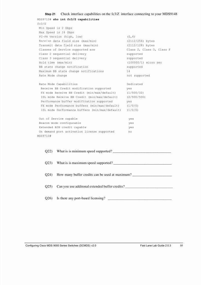
8/18/2019 FL_DCMDS_2.0.3_LG(1).pdf
http://slidepdf.com/reader/full/fldcmds203lg1pdf 91/482
Configuring Cisco MDS 9000 Series Switches (DCMDS) v2.0 Fast Lane Lab Guide 2.0.3 91
Step 21 Check interface capabilities on the fc3/Z interface connecting to your MDS9148
MDS9710# sho int fc3/Z capabilities
fc3/Z
Min Speed is 2 Gbps
Max Speed is 16 Gbps
FC-PH Version (high, low) (0,6)
Receive data field size (max/min) (2112/256) bytes
Transmit data field size (max/min) (2112/128) bytes
Classes of Service supported are Class 2, Class 3, Class FClass 2 sequential delivery supported
Class 3 sequential delivery supported
Hold time (max/min) (100000/1) micro sec
BB state change notification supported
Maximum BB state change notifications 14
Rate Mode change not supported
Rate Mode Capabilities Dedicated
Receive BB Credit modification supported yes
FX mode Receive BB Credit (min/max/default) (1/500/32)
ISL mode Receive BB Credit (min/max/default) (2/500/500)
Performance buffer modification supported yes
FX mode Performance buffers (min/max/default) (1/0/0)
ISL mode Performance buffers (min/max/default) (1/0/0)
Out of Service capable yes
Beacon mode configurable yes
Extended B2B credit capable yes
On demand port activation license supported no
MDS9710#
Q22) What is is minimum speed supported? ________________________________
Q23) What is is maximum speed supported? ________________________________
Q24) How many buffer credits can be used at maximum? ______________________
Q25) Can you use additonal extended buffer credits? __________________________
Q26) Is there any port-based licensing? ___________________________________
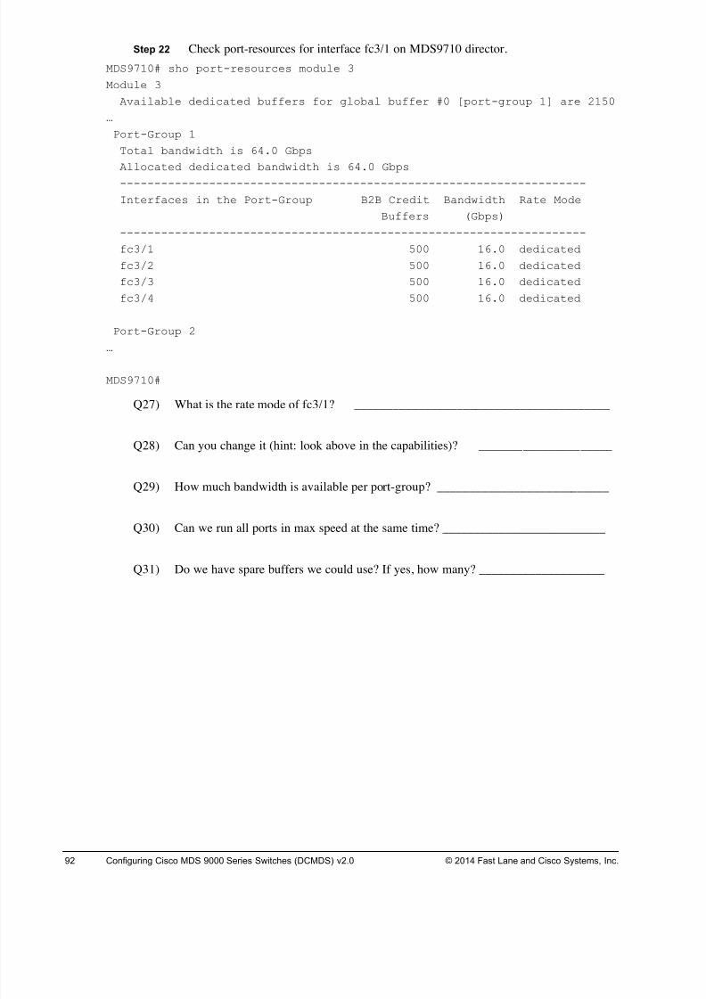
8/18/2019 FL_DCMDS_2.0.3_LG(1).pdf
http://slidepdf.com/reader/full/fldcmds203lg1pdf 92/482
92 Configuring Cisco MDS 9000 Series Switches (DCMDS) v2.0 © 2014 Fast Lane and Cisco Systems, Inc.
Step 22 Check port-resources for interface fc3/1 on MDS9710 director.
MDS9710# sho port-resources module 3
Module 3
Available dedicated buffers for global buffer #0 [port-group 1] are 2150
…
Port-Group 1
Total bandwidth is 64.0 Gbps
Allocated dedicated bandwidth is 64.0 Gbps
--------------------------------------------------------------------
Interfaces in the Port-Group B2B Credit Bandwidth Rate Mode
Buffers (Gbps)
--------------------------------------------------------------------
fc3/1 500 16.0 dedicated
fc3/2 500 16.0 dedicated
fc3/3 500 16.0 dedicated
fc3/4 500 16.0 dedicated
Port-Group 2
…
MDS9710#
Q27) What is the rate mode of fc3/1? ________________________________________
Q28) Can you change it (hint: look above in the capabilities)? _____________________
Q29) How much bandwidth is available per port-group? ___________________________
Q30) Can we run all ports in max speed at the same time? __________________________
Q31) Do we have spare buffers we could use? If yes, how many? ____________________
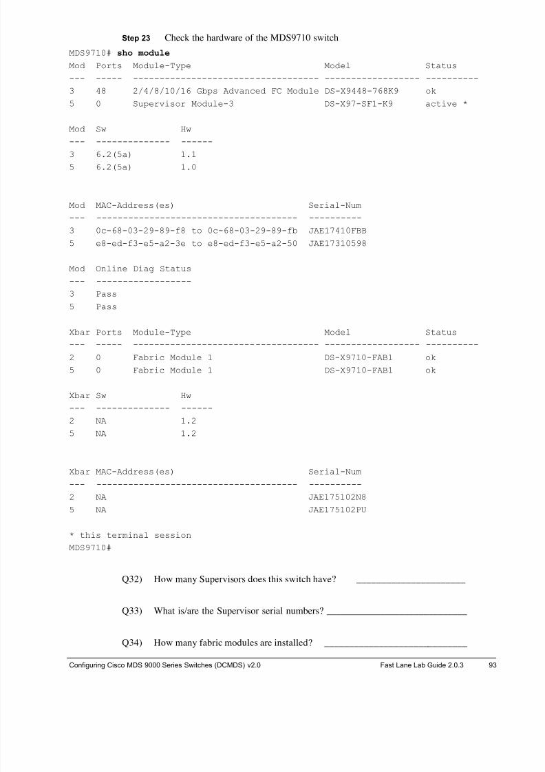
8/18/2019 FL_DCMDS_2.0.3_LG(1).pdf
http://slidepdf.com/reader/full/fldcmds203lg1pdf 93/482
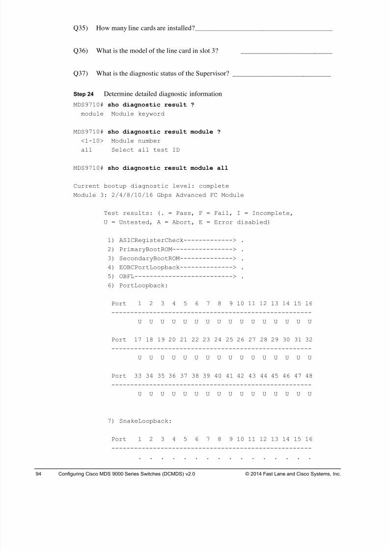
8/18/2019 FL_DCMDS_2.0.3_LG(1).pdf
http://slidepdf.com/reader/full/fldcmds203lg1pdf 94/482
94 Configuring Cisco MDS 9000 Series Switches (DCMDS) v2.0 © 2014 Fast Lane and Cisco Systems, Inc.
Q35) How many line cards are installed? _______________________________________
Q36) What is the model of the line card in slot 3? __________________________
Q37) What is the diagnostic status of the Supervisor? ____________________________
Step 24 Determine detailed diagnostic informationMDS9710# sho diagnostic result ?
module Module keyword
MDS9710# sho diagnostic result module ?
<1-10> Module number
all Select all test ID
MDS9710# sho diagnostic result module all
Current bootup diagnostic level: complete
Module 3: 2/4/8/10/16 Gbps Advanced FC Module
Test results: (. = Pass, F = Fail, I = Incomplete,
U = Untested, A = Abort, E = Error disabled)
1) ASICRegisterCheck-------------> .
2) PrimaryBootROM----------------> .
3) SecondaryBootROM--------------> .
4) EOBCPortLoopback--------------> .
5) OBFL--------------------------> .
6) PortLoopback:
Port 1 2 3 4 5 6 7 8 9 10 11 12 13 14 15 16
-----------------------------------------------------
U U U U U U U U U U U U U U U U
Port 17 18 19 20 21 22 23 24 25 26 27 28 29 30 31 32
-----------------------------------------------------
U U U U U U U U U U U U U U U U
Port 33 34 35 36 37 38 39 40 41 42 43 44 45 46 47 48
-----------------------------------------------------U U U U U U U U U U U U U U U U
7) SnakeLoopback:
Port 1 2 3 4 5 6 7 8 9 10 11 12 13 14 15 16
-----------------------------------------------------
. . . . . . . . . . . . . . . .
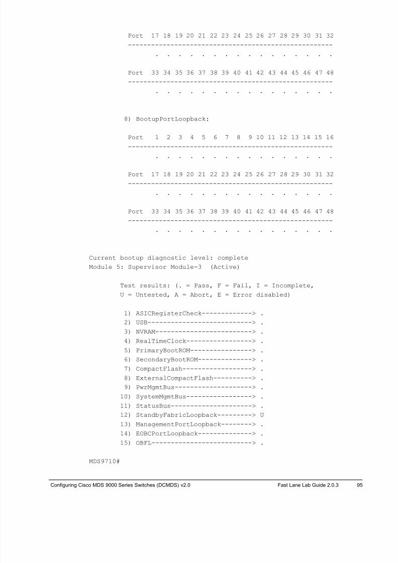
8/18/2019 FL_DCMDS_2.0.3_LG(1).pdf
http://slidepdf.com/reader/full/fldcmds203lg1pdf 95/482
Configuring Cisco MDS 9000 Series Switches (DCMDS) v2.0 Fast Lane Lab Guide 2.0.3 95
Port 17 18 19 20 21 22 23 24 25 26 27 28 29 30 31 32
-----------------------------------------------------
. . . . . . . . . . . . . . . .
Port 33 34 35 36 37 38 39 40 41 42 43 44 45 46 47 48
-----------------------------------------------------
. . . . . . . . . . . . . . . .
8) BootupPortLoopback:
Port 1 2 3 4 5 6 7 8 9 10 11 12 13 14 15 16
-----------------------------------------------------
. . . . . . . . . . . . . . . .
Port 17 18 19 20 21 22 23 24 25 26 27 28 29 30 31 32
-----------------------------------------------------
. . . . . . . . . . . . . . . .
Port 33 34 35 36 37 38 39 40 41 42 43 44 45 46 47 48
-----------------------------------------------------
. . . . . . . . . . . . . . . .
Current bootup diagnostic level: complete
Module 5: Supervisor Module-3 (Active)
Test results: (. = Pass, F = Fail, I = Incomplete,
U = Untested, A = Abort, E = Error disabled)
1) ASICRegisterCheck-------------> .
2) USB---------------------------> .
3) NVRAM-------------------------> .
4) RealTimeClock-----------------> .
5) PrimaryBootROM----------------> .
6) SecondaryBootROM--------------> .
7) CompactFlash------------------> .
8) ExternalCompactFlash----------> .
9) PwrMgmtBus--------------------> .
10) SystemMgmtBus-----------------> .
11) StatusBus---------------------> .
12) StandbyFabricLoopback---------> U
13) ManagementPortLoopback--------> .
14) EOBCPortLoopback--------------> .
15) OBFL--------------------------> .
MDS9710#
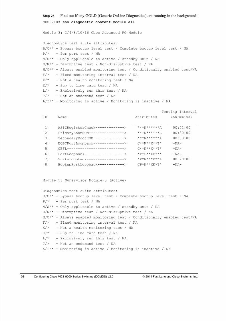
8/18/2019 FL_DCMDS_2.0.3_LG(1).pdf
http://slidepdf.com/reader/full/fldcmds203lg1pdf 96/482
96 Configuring Cisco MDS 9000 Series Switches (DCMDS) v2.0 © 2014 Fast Lane and Cisco Systems, Inc.
Step 25 Find out if any GOLD (Generic OnLine Diagnostics) are running in the background:
MDS9710# sho diagnostic content module all
Module 3: 2/4/8/10/16 Gbps Advanced FC Module
Diagnostics test suite attributes:
B/C/* - Bypass bootup level test / Complete bootup level test / NA
P/* - Per port test / NA
M/S/* - Only applicable to active / standby unit / NA
D/N/* - Disruptive test / Non-disruptive test / NA
H/O/* - Always enabled monitoring test / Conditionally enabled test/NA
F/* - Fixed monitoring interval test / NA
X/* - Not a health monitoring test / NA
E/* - Sup to line card test / NA
L/* - Exclusively run this test / NA
T/* - Not an ondemand test / NA
A/I/* - Monitoring is active / Monitoring is inactive / NA
Testing IntervalID Name Attributes (hh:mm:ss)
____ __________________________________ ____________ _____________
1) ASICRegisterCheck-------------> ***N******A 00:01:00
2) PrimaryBootROM----------------> ***N******A 00:30:00
3) SecondaryBootROM--------------> ***N******A 00:30:00
4) EOBCPortLoopback--------------> C**N**X**T* -NA-
5) OBFL--------------------------> C**N**X**T* -NA-
6) PortLoopback------------------> *P*D**XE*** -NA-
7) SnakeLoopback-----------------> *P*N***E**A 00:20:00
8) BootupPortLoopback------------> CP*N**XE*T* -NA-
Module 5: Supervisor Module-3 (Active)
Diagnostics test suite attributes:
B/C/* - Bypass bootup level test / Complete bootup level test / NA
P/* - Per port test / NA
M/S/* - Only applicable to active / standby unit / NA
D/N/* - Disruptive test / Non-disruptive test / NA
H/O/* - Always enabled monitoring test / Conditionally enabled test/NA
F/* - Fixed monitoring interval test / NA
X/* - Not a health monitoring test / NA
E/* - Sup to line card test / NA
L/* - Exclusively run this test / NA
T/* - Not an ondemand test / NA
A/I/* - Monitoring is active / Monitoring is inactive / NA
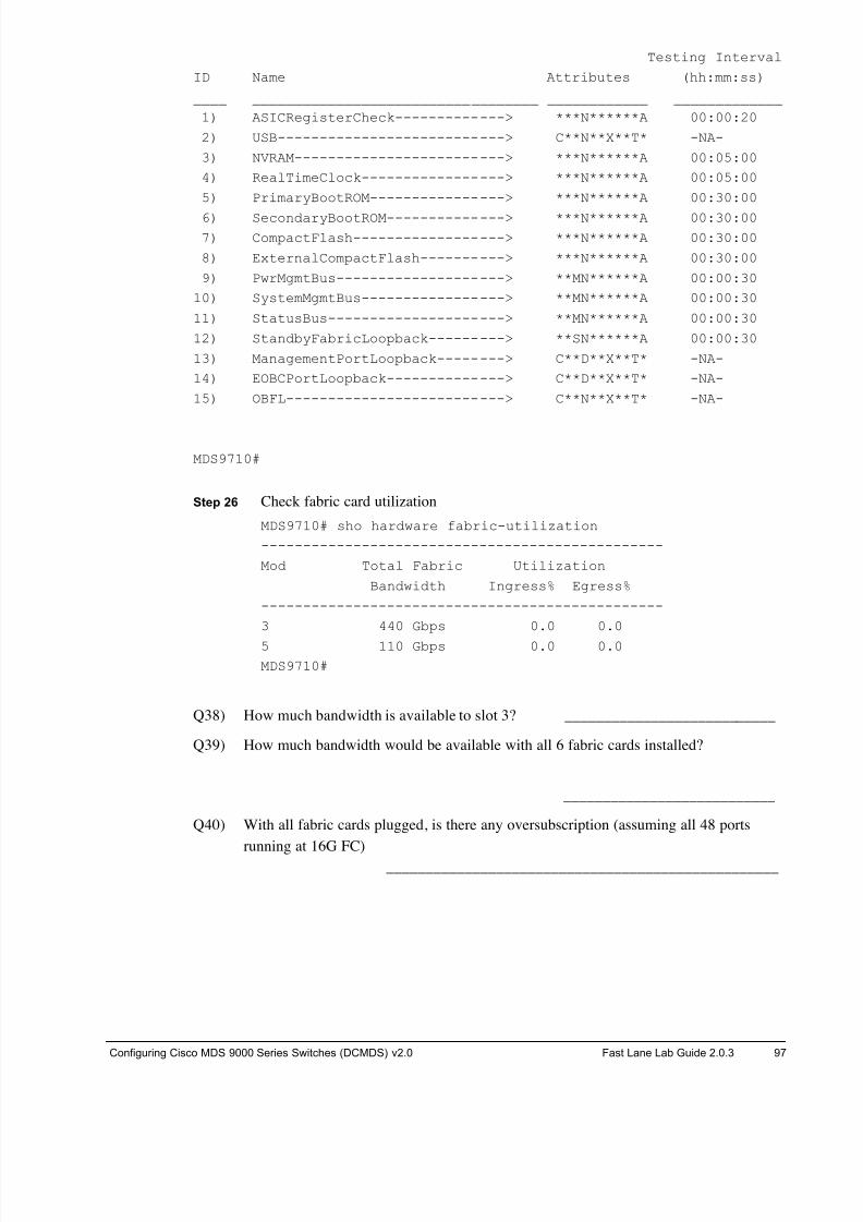
8/18/2019 FL_DCMDS_2.0.3_LG(1).pdf
http://slidepdf.com/reader/full/fldcmds203lg1pdf 97/482
Configuring Cisco MDS 9000 Series Switches (DCMDS) v2.0 Fast Lane Lab Guide 2.0.3 97
Testing Interval
ID Name Attributes (hh:mm:ss)
____ __________________________________ ____________ _____________
1) ASICRegisterCheck-------------> ***N******A 00:00:20
2) USB---------------------------> C**N**X**T* -NA-
3) NVRAM-------------------------> ***N******A 00:05:00
4) RealTimeClock-----------------> ***N******A 00:05:00
5) PrimaryBootROM----------------> ***N******A 00:30:00
6) SecondaryBootROM--------------> ***N******A 00:30:00
7) CompactFlash------------------> ***N******A 00:30:00
8) ExternalCompactFlash----------> ***N******A 00:30:00
9) PwrMgmtBus--------------------> **MN******A 00:00:30
10) SystemMgmtBus-----------------> **MN******A 00:00:30
11) StatusBus---------------------> **MN******A 00:00:30
12) StandbyFabricLoopback---------> **SN******A 00:00:30
13) ManagementPortLoopback--------> C**D**X**T* -NA-
14) EOBCPortLoopback--------------> C**D**X**T* -NA-
15) OBFL--------------------------> C**N**X**T* -NA-
MDS9710#
Step 26 Check fabric card utilization
MDS9710# sho hardware fabric-utilization
------------------------------------------------
Mod Total Fabric Utilization
Bandwidth Ingress% Egress%
------------------------------------------------
3 440 Gbps 0.0 0.0
5 110 Gbps 0.0 0.0
MDS9710#
Q38) How much bandwidth is available to slot 3? ___________________________
Q39) How much bandwidth would be available with all 6 fabric cards installed?
___________________________
Q40) With all fabric cards plugged, is there any oversubscription (assuming all 48 ports
running at 16G FC)
__________________________________________________
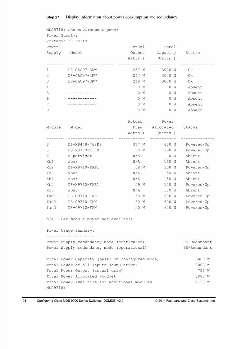
8/18/2019 FL_DCMDS_2.0.3_LG(1).pdf
http://slidepdf.com/reader/full/fldcmds203lg1pdf 98/482
98 Configuring Cisco MDS 9000 Series Switches (DCMDS) v2.0 © 2014 Fast Lane and Cisco Systems, Inc.
Step 27 Display information about power consumption and redundancy.
MDS9710# sho environment power
Power Supply:
Voltage: 50 Volts
Power Actual Total
Supply Model Output Capacity Status
(Watts ) (Watts )
------- ------------------- ----------- ----------- --------------
1 DS-CAC97-3KW 257 W 3000 W Ok
2 DS-CAC97-3KW 247 W 3000 W Ok
3 DS-CAC97-3KW 248 W 3000 W Ok
4 ------------ 0 W 0 W Absent
5 ------------ 0 W 0 W Absent
6 ------------ 0 W 0 W Absent
7 ------------ 0 W 0 W Absent
8 ------------ 0 W 0 W Absent
Actual PowerModule Model Draw Allocated Status
(Watts ) (Watts )
------- ------------------- ----------- ----------- --------------
3 DS-X9448-768K9 377 W 650 W Powered-Up
5 DS-X97-SF1-K9 98 W 190 W Powered-Up
6 supervisor N/A 0 W Absent
Xb1 xbar N/A 150 W Absent
Xb2 DS-X9710-FAB1 58 W 150 W Powered-Up
Xb3 xbar N/A 150 W Absent
Xb4 xbar N/A 150 W Absent
Xb5 DS-X9710-FAB1 59 W 150 W Powered-Up
Xb6 xbar N/A 150 W Absent
fan1 DS-C9710-FAN 50 W 600 W Powered-Up
fan2 DS-C9710-FAN 50 W 600 W Powered-Up
fan3 DS-C9710-FAN 50 W 600 W Powered-Up
N/A - Per module power not available
Power Usage Summary:
--------------------
Power Supply redundancy mode (configured) PS-Redundant
Power Supply redundancy mode (operational) PS-Redundant
Total Power Capacity (based on configured mode) 6000 W
Total Power of all Inputs (cumulative) 9000 W
Total Power Output (actual draw) 752 W
Total Power Allocated (budget) 3880 W
Total Power Available for additional modules 2120 W
MDS9710#
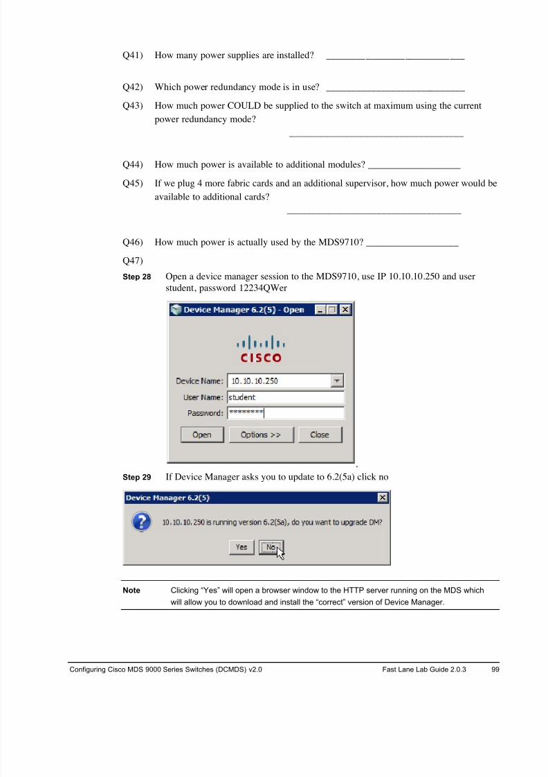
8/18/2019 FL_DCMDS_2.0.3_LG(1).pdf
http://slidepdf.com/reader/full/fldcmds203lg1pdf 99/482
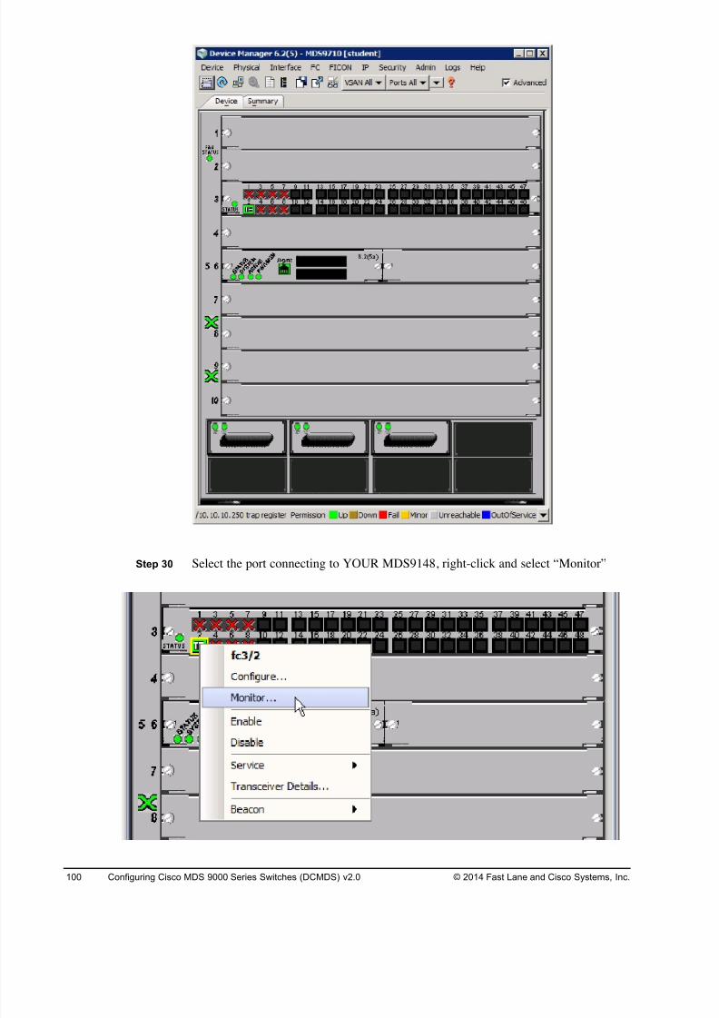
8/18/2019 FL_DCMDS_2.0.3_LG(1).pdf
http://slidepdf.com/reader/full/fldcmds203lg1pdf 100/482
100 Configuring Cisco MDS 9000 Series Switches (DCMDS) v2.0 © 2014 Fast Lane and Cisco Systems, Inc.
Step 30 Select the port connecting to YOUR MDS9148, right-click and select “Monitor”
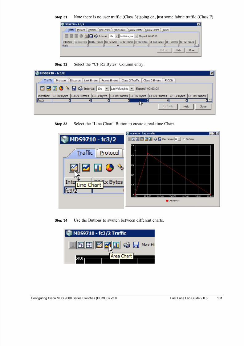
8/18/2019 FL_DCMDS_2.0.3_LG(1).pdf
http://slidepdf.com/reader/full/fldcmds203lg1pdf 101/482
Configuring Cisco MDS 9000 Series Switches (DCMDS) v2.0 Fast Lane Lab Guide 2.0.3 101
Step 31 Note there is no user traffic (Class 3) going on, just some fabric traffic (Class F)
Step 32 Select the “CF Rx Bytes” Column entry.
Step 33 Select the “Line Chart” Button to create a real-time Chart.
Step 34 Use the Buttons to swutch between different charts.
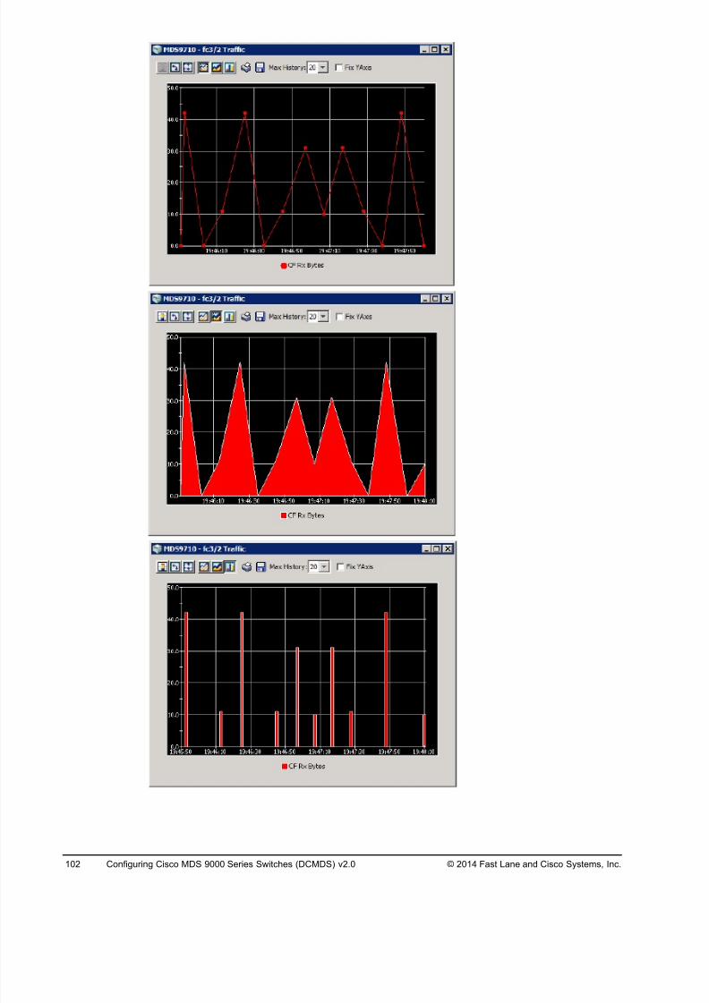
8/18/2019 FL_DCMDS_2.0.3_LG(1).pdf
http://slidepdf.com/reader/full/fldcmds203lg1pdf 102/482
102 Configuring Cisco MDS 9000 Series Switches (DCMDS) v2.0 © 2014 Fast Lane and Cisco Systems, Inc.
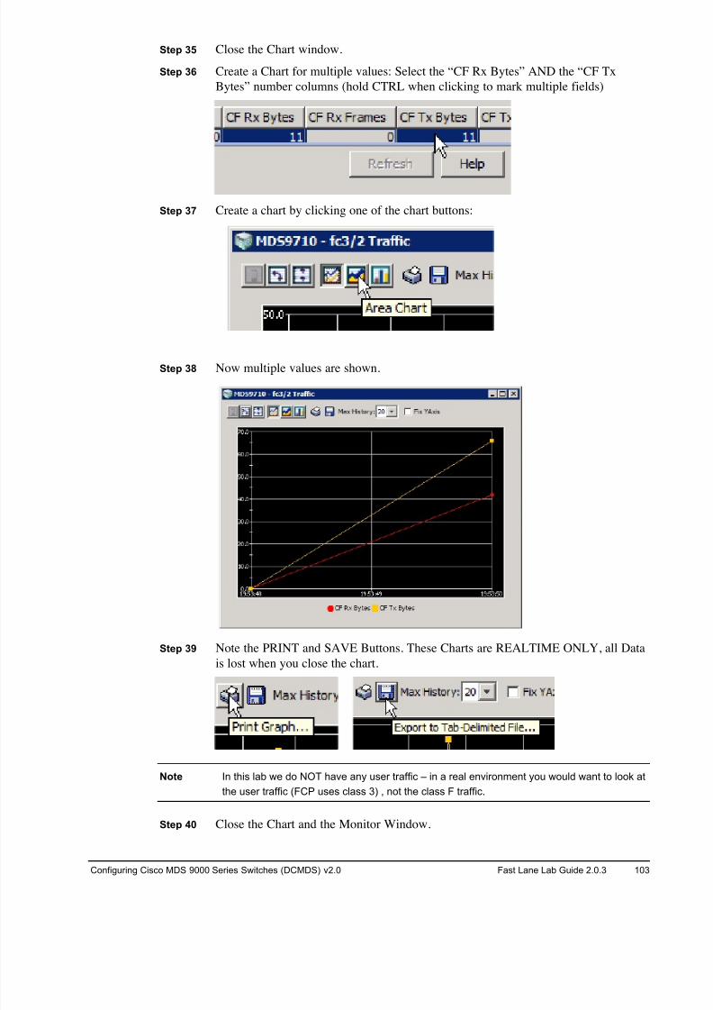
8/18/2019 FL_DCMDS_2.0.3_LG(1).pdf
http://slidepdf.com/reader/full/fldcmds203lg1pdf 103/482
Configuring Cisco MDS 9000 Series Switches (DCMDS) v2.0 Fast Lane Lab Guide 2.0.3 103
Step 35 Close the Chart window.
Step 36 Create a Chart for multiple values: Select the “CF Rx Bytes” AND the “CF Tx
Bytes” number columns (hold CTRL when clicking to mark multiple fields)
Step 37 Create a chart by clicking one of the chart buttons:
Step 38 Now multiple values are shown.
Step 39 Note the PRINT and SAVE Buttons. These Charts are REALTIME ONLY, all Data
is lost when you close the chart.
Note In this lab we do NOT have any user traffic – in a real environment you would want to look at
the user traffic (FCP uses class 3) , not the class F traffic.
Step 40 Close the Chart and the Monitor Window.
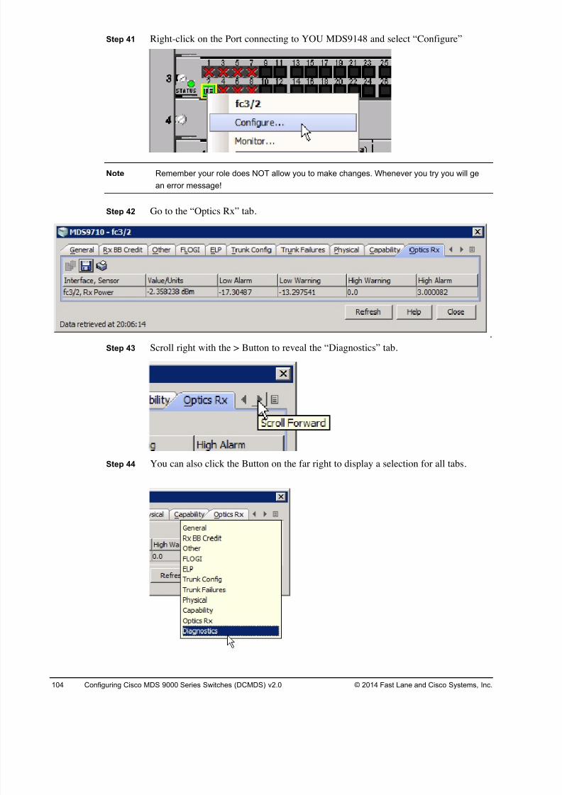
8/18/2019 FL_DCMDS_2.0.3_LG(1).pdf
http://slidepdf.com/reader/full/fldcmds203lg1pdf 104/482
104 Configuring Cisco MDS 9000 Series Switches (DCMDS) v2.0 © 2014 Fast Lane and Cisco Systems, Inc.
Step 41 Right-click on the Port connecting to YOU MDS9148 and select “Configure”
Note Remember your role does NOT allow you to make changes. Whenever you try you will ge
an error message!
Step 42 Go to the “Optics Rx” tab.
Step 43 Scroll right with the > Button to reveal the “Diagnostics” tab.
Step 44 You can also click the Button on the far right to display a selection for all tabs.
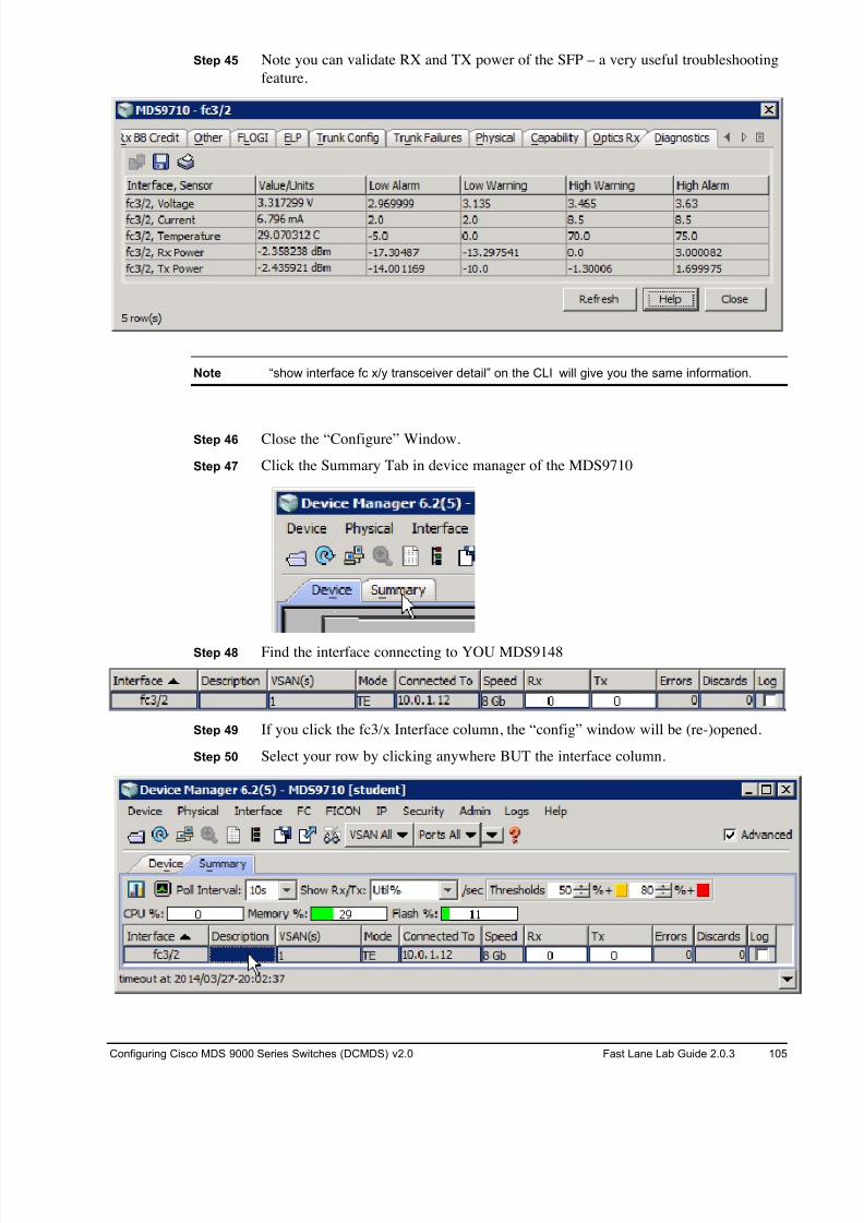
8/18/2019 FL_DCMDS_2.0.3_LG(1).pdf
http://slidepdf.com/reader/full/fldcmds203lg1pdf 105/482
Configuring Cisco MDS 9000 Series Switches (DCMDS) v2.0 Fast Lane Lab Guide 2.0.3 105
Step 45 Note you can validate RX and TX power of the SFP – a very useful troubleshooting
feature.
Note “show interface fc x/y transceiver detail” on the CLI will give you the same information.
Step 46 Close the “Configure” Window.
Step 47 Click the Summary Tab in device manager of the MDS9710
Step 48 Find the interface connecting to YOU MDS9148
Step 49 If you click the fc3/x Interface column, the “config” window will be (re-)opened.
Step 50 Select your row by clicking anywhere BUT the interface column.
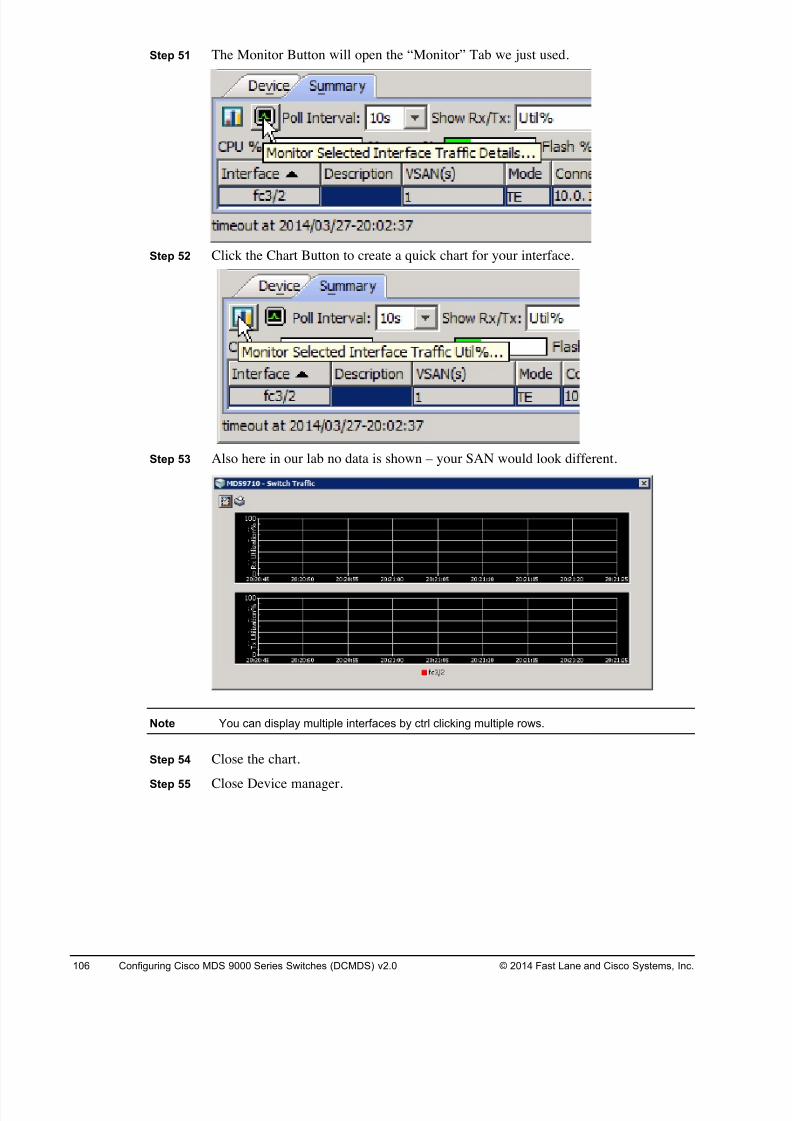
8/18/2019 FL_DCMDS_2.0.3_LG(1).pdf
http://slidepdf.com/reader/full/fldcmds203lg1pdf 106/482
106 Configuring Cisco MDS 9000 Series Switches (DCMDS) v2.0 © 2014 Fast Lane and Cisco Systems, Inc.
Step 51 The Monitor Button will open the “Monitor” Tab we just used.
Step 52 Click the Chart Button to create a quick chart for your interface.
Step 53 Also here in our lab no data is shown – your SAN would look different.
Note You can display multiple interfaces by ctrl clicking multiple rows.
Step 54 Close the chart.
Step 55 Close Device manager.
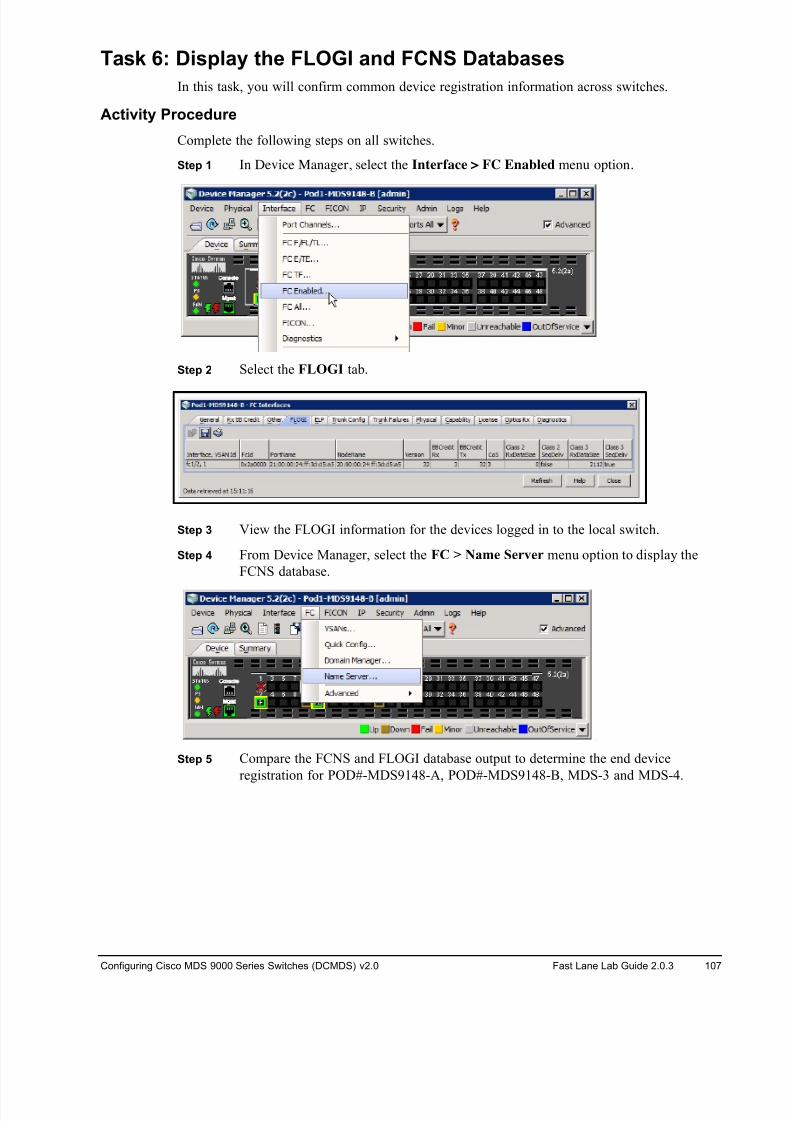
8/18/2019 FL_DCMDS_2.0.3_LG(1).pdf
http://slidepdf.com/reader/full/fldcmds203lg1pdf 107/482
Configuring Cisco MDS 9000 Series Switches (DCMDS) v2.0 Fast Lane Lab Guide 2.0.3 107
Task 6: Display the FLOGI and FCNS Databases
In this task, you will confirm common device registration information across switches.
Activity Procedure
Complete the following steps on all switches.
Step 1 In Device Manager, select the Interface > FC Enabled menu option.
Step 2 Select the FLOGI tab.
Step 3 View the FLOGI information for the devices logged in to the local switch.
Step 4 From Device Manager, select the FC > Name Server menu option to display the
FCNS database.
Step 5 Compare the FCNS and FLOGI database output to determine the end device
registration for POD#-MDS9148-A, POD#-MDS9148-B, MDS-3 and MDS-4.
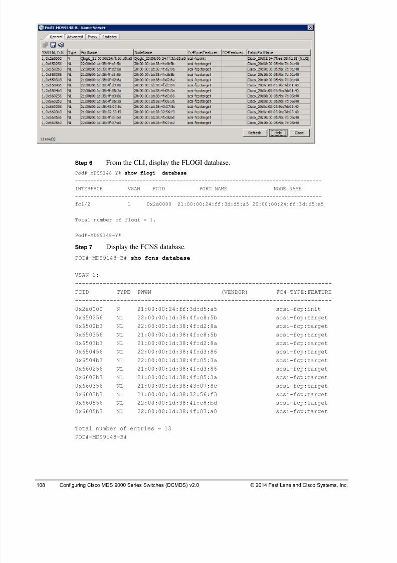
8/18/2019 FL_DCMDS_2.0.3_LG(1).pdf
http://slidepdf.com/reader/full/fldcmds203lg1pdf 108/482
108 Configuring Cisco MDS 9000 Series Switches (DCMDS) v2.0 © 2014 Fast Lane and Cisco Systems, Inc.
Step 6 From the CLI, display the FLOGI database.
Pod#-MDS9148-Y# show flogi database
--------------------------------------------------------------------------------
INTERFACE VSAN FCID PORT NAME NODE NAME
--------------------------------------------------------------------------------fc1/2 1 0x2a0000 21:00:00:24:ff:3d:d5:a5 20:00:00:24:ff:3d:d5:a5
Total number of flogi = 1.
Pod#-MDS9148-Y#
Step 7 Display the FCNS database.
POD#-MDS9148-B# sho fcns database
VSAN 1:
--------------------------------------------------------------------------
FCID TYPE PWWN (VENDOR) FC4-TYPE:FEATURE
--------------------------------------------------------------------------
0x2a0000 N 21:00:00:24:ff:3d:d5:a5 scsi-fcp:init
0x650256 NL 22:00:00:1d:38:4f:c8:5b scsi-fcp:target
0x6502b3 NL 22:00:00:1d:38:4f:d2:8a scsi-fcp:target
0x650356 NL 21:00:00:1d:38:4f:c8:5b scsi-fcp:target
0x6503b3 NL 21:00:00:1d:38:4f:d2:8a scsi-fcp:target
0x650456 NL 22:00:00:1d:38:4f:d3:86 scsi-fcp:target
0x6504b3 NL 22:00:00:1d:38:4f:05:3a scsi-fcp:target
0x660256 NL 21:00:00:1d:38:4f:d3:86 scsi-fcp:target
0x6602b3 NL 21:00:00:1d:38:4f:05:3a scsi-fcp:target
0x660356 NL 21:00:00:1d:38:43:07:8c scsi-fcp:target
0x6603b3 NL 21:00:00:1d:38:32:56:f3 scsi-fcp:target0x660556 NL 22:00:00:1d:38:4f:c8:bd scsi-fcp:target
0x6605b3 NL 22:00:00:1d:38:4f:07:a0 scsi-fcp:target
Total number of entries = 13
POD#-MDS9148-B#
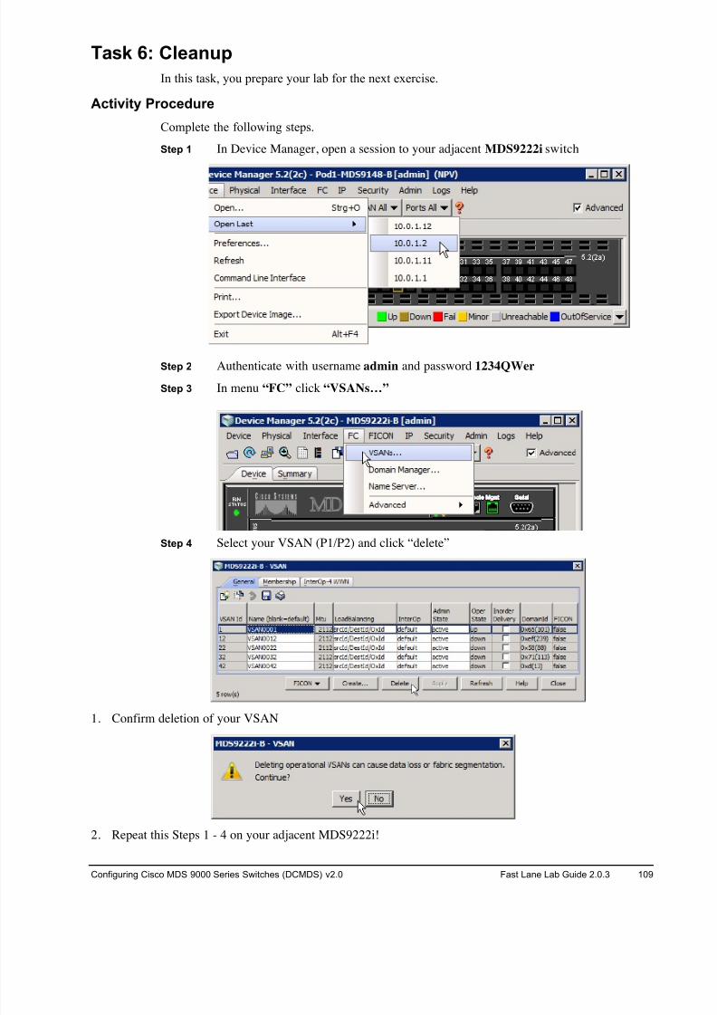
8/18/2019 FL_DCMDS_2.0.3_LG(1).pdf
http://slidepdf.com/reader/full/fldcmds203lg1pdf 109/482
Configuring Cisco MDS 9000 Series Switches (DCMDS) v2.0 Fast Lane Lab Guide 2.0.3 109
Task 6: Cleanup
In this task, you prepare your lab for the next exercise.
Activity Procedure
Complete the following steps.
Step 1 In Device Manager, open a session to your adjacent MDS9222i switch
Step 2 Authenticate with username admin and password 1234QWer
Step 3 In menu “FC” click “VSANs…”
Step 4 Select your VSAN (P1/P2) and click “delete”
1. Confirm deletion of your VSAN
2. Repeat this Steps 1 - 4 on your adjacent MDS9222i!
8/18/2019 FL_DCMDS_2.0.3_LG(1).pdf
http://slidepdf.com/reader/full/fldcmds203lg1pdf 110/482
110 Configuring Cisco MDS 9000 Series Switches (DCMDS) v2.0 © 2014 Fast Lane and Cisco Systems, Inc.
3. Open a console session to your assigned switch (MDS9148-A or MDS9148-B) by clicking the blue
switch icon in the remote lab GUI.
Switch login: admin
Password: 1234QWer
4. Clear the current startup configuration ON YOUR 9148s ONLY, DO NOT CLEAR THE CORE
9222is!!! .
# write erase
The following message is displayed:Warning: This command will erase the startup-configuration.
Do you wish to proceed anyway? [y/n] [N]
Type y to proceed.
5. Reboot the 9148 switch.
# reload
This command will reboot the system. (y/n)?
Type y to proceed.
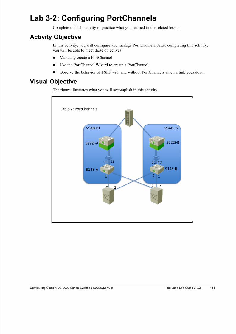
8/18/2019 FL_DCMDS_2.0.3_LG(1).pdf
http://slidepdf.com/reader/full/fldcmds203lg1pdf 111/482
Configuring Cisco MDS 9000 Series Switches (DCMDS) v2.0 Fast Lane Lab Guide 2.0.3 111
Lab 3-2: Configuring PortChannels Complete this lab activity to practice what you learned in the related lesson.
Activity Objective
In this activity, you will configure and manage PortChannels. After completing this activity,
you will be able to meet these objectives:
! Manually create a PortChannel
! Use the PortChannel Wizard to create a PortChannel
! Observe the behavior of FSPF with and without PortChannels when a link goes down
Visual Objective
The figure illustrates what you will accomplish in this activity.
! !#
!# !! !#!!
!# #!
$!%&'( $!%&')
$###*'( $###*')
+,- .'#/ 012345,66789
:;(< 0! :;(< 0#
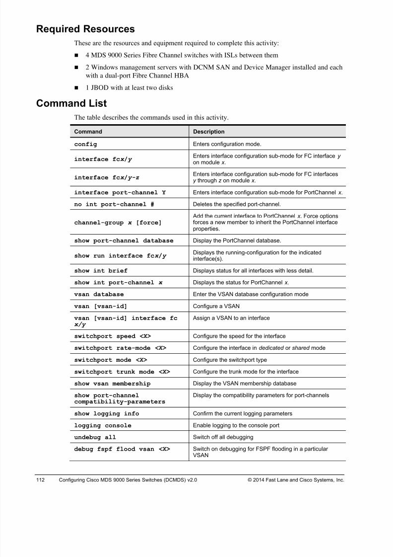
8/18/2019 FL_DCMDS_2.0.3_LG(1).pdf
http://slidepdf.com/reader/full/fldcmds203lg1pdf 112/482
112 Configuring Cisco MDS 9000 Series Switches (DCMDS) v2.0 © 2014 Fast Lane and Cisco Systems, Inc.
Required Resources
These are the resources and equipment required to complete this activity:
! 4 MDS 9000 Series Fibre Channel switches with ISLs between them
! 2 Windows management servers with DCNM SAN and Device Manager installed and each
with a dual-port Fibre Channel HBA
! 1 JBOD with at least two disks
Command List
The table describes the commands used in this activity.
Command Description
config Enters configuration mode.
interface fcx / y Enters interface configuration sub-mode for FC interface y on module x .
interface fcx / y-z Enters interface configuration sub-mode for FC interfacesy through z on module x .
interface port-channel Y Enters interface configuration sub-mode for PortChannel x .
no int port-channel # Deletes the specified port-channel.
channel-group x [force] Add the current interface to PortChannel x . Force optionsforces a new member to inherit the PortChannel interfaceproperties.
show port-channel database Display the PortChannel database.
show run interface fcx / y Displays the running-configuration for the indicatedinterface(s).
show int brief Displays status for all interfaces with less detail.
show int port-channel x Displays the status for PortChannel x.
vsan database Enter the VSAN database configuration mode
vsan [vsan-id] Configure a VSAN
vsan [vsan-id] interface fcx/y
Assign a VSAN to an interface
switchport speed <X> Configure the speed for the interface
switchport rate-mode <X> Configure the interface in dedicated or shared mode
switchport mode <X> Configure the switchport type
switchport trunk mode <X> Configure the trunk mode for the interface
show vsan membership Display the VSAN membership database
show port-channelcompatibility-parameters
Display the compatibility parameters for port-channels
show logging info Confirm the current logging parameters
logging console Enable logging to the console port
undebug all Switch off all debugging
debug fspf flood vsan <X> Switch on debugging for FSPF flooding in a particularVSAN

8/18/2019 FL_DCMDS_2.0.3_LG(1).pdf
http://slidepdf.com/reader/full/fldcmds203lg1pdf 113/482
Configuring Cisco MDS 9000 Series Switches (DCMDS) v2.0 Fast Lane Lab Guide 2.0.3 113
show debug Display the current debug configuration
copy run start Copy the running-configuration to startup-configuration

8/18/2019 FL_DCMDS_2.0.3_LG(1).pdf
http://slidepdf.com/reader/full/fldcmds203lg1pdf 114/482
114 Configuring Cisco MDS 9000 Series Switches (DCMDS) v2.0 © 2014 Fast Lane and Cisco Systems, Inc.
Task 1: Complete the Initial Switch Configuration
In this task, you complete the initial switch configuration process.
Note If you are working in teams within a pod, one student will configure Fabric A / MDS9148-A
and the other student will configure Fabric B / MDS9148-B. If you are working alone, you
will need to configure both switches/fabrics!
Activity Procedure
Complete the following steps on both MDS switches:
Step 1 Open a console session to your assigned switch (MDS9148-A or MDS9148-B) by
clicking the blue switch icon in the remote lab GUI.
Note If the switch asks for username and password at this step log in with user “admin” and
password “1234QWer”, erase the configuration and reboot.
Step 2 After the switch reboots, it will automatically launch the setup process. Answer the
questions according to the following example, replacing your pod number and
switch ID where appropriate.---- System Admin Account Setup ----
Do you want to enforce secure password standard (yes/no) [y]: y
Enter the password for "admin": 1234QWer < note QW is UPPERCASE
Confirm the password for "admin":1234QWer
Caution DO NOT USE ANY OTHER PASSWORD. This may force the lab support management
software to recover passwords and your configuration may be deleted.
--- Basic System Configuration Dialog ---
This setup utility will guide you through the basic configuration ofthe system. Setup configures only enough connectivity for managementof the system.
Please register Cisco MDS 9000 Family devices promptly with yoursupplier. Failure to register may affect response times for initialservice calls. MDS devices must be registered to receive entitledsupport services.
Press Enter at anytime to skip a dialog. Use ctrl-c at anytime to skipthe remaining dialogs.
Would you like to enter the basic configuration dialog (yes/no): y
Create another login account (yes/no) [n]: <Enter>
Configure read-only SNMP community string (yes/no) [n]: <Enter>
Configure read-write SNMP community string (yes/no) [n]: <Enter>
Enter the switch name: Pod#-MDS9148-Y (where # is your pod number and Y is the
switch ID; for example: POD#-MDS9148-A)
Continue with Out-of-band (mgmt0) management configuration? (yes/no)[y]: <Enter>
Mgmt0 IPv4 address : <10.0.1.PN >
(where P is your Pod# and N is 1 for MDS9148-A and 2 for MDS9148-B)
Mgmt0 IPv4 netmask : 255.255.255.0

8/18/2019 FL_DCMDS_2.0.3_LG(1).pdf
http://slidepdf.com/reader/full/fldcmds203lg1pdf 115/482
Configuring Cisco MDS 9000 Series Switches (DCMDS) v2.0 Fast Lane Lab Guide 2.0.3 115
Configure the default gateway? (yes/no) [y]: <No>
Configure advanced IP options? (yes/no) [n]: <Enter>
Enable the ssh service? (yes/no) [y]: <No>
Enable the telnet service? (yes/no) [n]: <Yes>
Configure congestion/no_credit drop for fc interfaces? (yes/no)[y]: <Enter>
Enter the type of drop to configure congestion/no_credit drop?
(con/no) [c]: <Enter>Enter milliseconds in multiple of 10 for congestion-drop in range [100- 500], or [d/default] for default: <d>
Enter mode for congestion/no_credit drop[E/F]: <Enter>
Enable the http-server? (yes/no) [y]: <Enter>
Configure clock? (yes/no) [n]: <Enter>
Configure timezone? (yes/no) [n]: <Enter>
Configure summertime? (yes/no) [n]: <Enter>
Configure the ntp server? (yes/no) [n]: <Enter>
Configure default switchport interface state (shut/noshut) [shut]: <Enter>
Configure default switchport trunk mode (on/off/auto) [on]: <Enter> Configure default switchport port mode F (yes/no) [n]: <Enter>
Configure default zone policy (permit/deny) [deny]: <Enter>
Enable full zoneset distribution (yes/no) [n]: <Enter>
Configure default zone mode (basic/enhanced) [basic]: <Enter>
Step 3 A summary of the configuration will be displayed:
The following configuration will be applied:
password strength-check
switchname POD#-MDS9148-A
interface mgmt0
ip address 10.0.1.PN 255.255.255.0
no shutdown
no feature ssh
feature telnet
feature http-server
system default switchport shutdown
system default switchport trunk mode on
no system default zone default-zone permit
no system default zone distribute full
no system default zone mode enhanced
Step 4 Press Enter twice to save the configuration.
Would you like to edit the configuration? (yes/no) [n]: <Enter>
Use this configuration and save it? (yes/no) [y]: <Enter>
Step 5 You will now use Device Manager to enable the links between the switches you are
managing. Launch Device Manager.
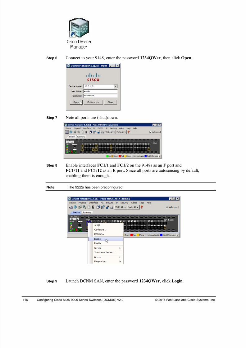
8/18/2019 FL_DCMDS_2.0.3_LG(1).pdf
http://slidepdf.com/reader/full/fldcmds203lg1pdf 116/482
116 Configuring Cisco MDS 9000 Series Switches (DCMDS) v2.0 © 2014 Fast Lane and Cisco Systems, Inc.
Step 6 Connect to your 9148, enter the password 1234QWer, then click Open.
Step 7 Note all ports are (shut)down.
Step 8 Enable interfaces FC1/1 and FC1/2 on the 9148s as an F port and
FC1/11 and FC1/12 as an E port. Since all ports are autosensing by default,
enabling them is enough.
Note The 9222i has been preconfigured.
Step 9 Launch DCNM SAN, enter the password 1234QWer, click Login.
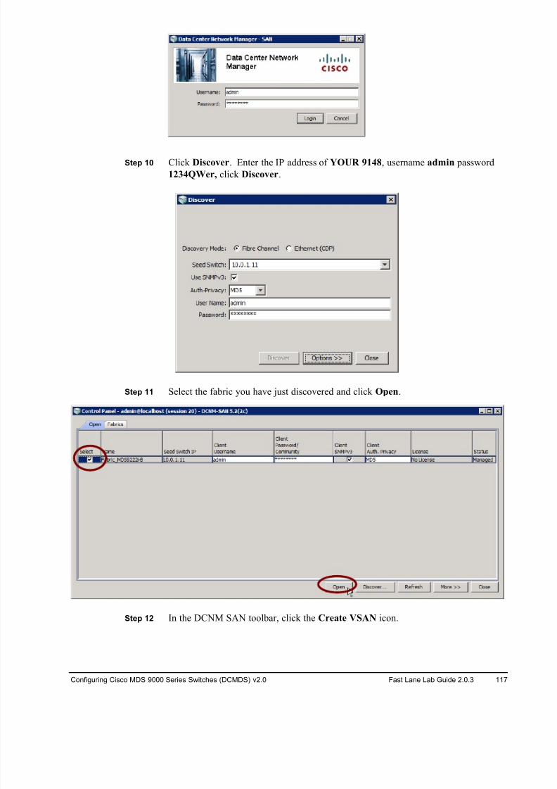
8/18/2019 FL_DCMDS_2.0.3_LG(1).pdf
http://slidepdf.com/reader/full/fldcmds203lg1pdf 117/482
Configuring Cisco MDS 9000 Series Switches (DCMDS) v2.0 Fast Lane Lab Guide 2.0.3 117
Step 10 Click Discover. Enter the IP address of YOUR 9148, username admin password
1234QWer, click Discover.
Step 11 Select the fabric you have just discovered and click Open.
Step 12 In the DCNM SAN toolbar, click the Create VSAN icon.
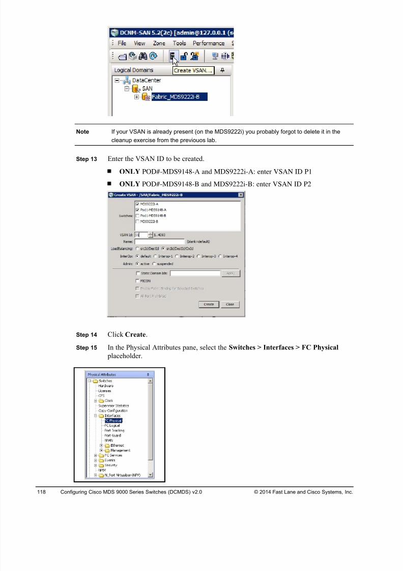
8/18/2019 FL_DCMDS_2.0.3_LG(1).pdf
http://slidepdf.com/reader/full/fldcmds203lg1pdf 118/482
118 Configuring Cisco MDS 9000 Series Switches (DCMDS) v2.0 © 2014 Fast Lane and Cisco Systems, Inc.
Note If your VSAN is already present (on the MDS9222i) you probably forgot to delete it in the
cleanup exercise from the previouos lab.
Step 13 Enter the VSAN ID to be created.
ONLY POD#-MDS9148-A and MDS9222i-A: enter VSAN ID P1
ONLY POD#-MDS9148-B and MDS9222i-B: enter VSAN ID P2
Step 14 Click Create.
Step 15 In the Physical Attributes pane, select the Switches > Interfaces > FC Physical
placeholder.
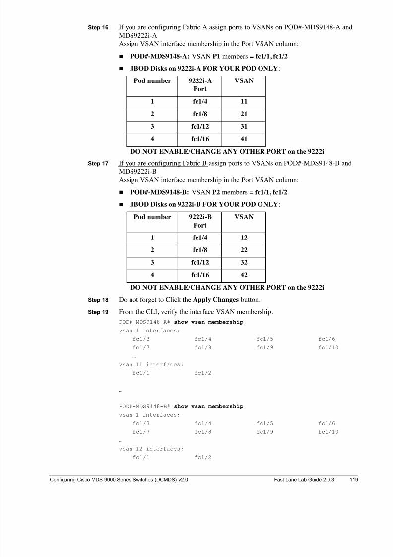
8/18/2019 FL_DCMDS_2.0.3_LG(1).pdf
http://slidepdf.com/reader/full/fldcmds203lg1pdf 119/482
Configuring Cisco MDS 9000 Series Switches (DCMDS) v2.0 Fast Lane Lab Guide 2.0.3 119
Step 16 If you are configuring Fabric A assign ports to VSANs on POD#-MDS9148-A and
MDS9222i-A
Assign VSAN interface membership in the Port VSAN column:
! POD#-MDS9148-A: VSAN P1 members = fc1/1, fc1/2
! JBOD Disks on 9222i-A FOR YOUR POD ONLY:
Pod number 9222i-A
Port
VSAN
1 fc1/4 11
2 fc1/8 21
3 fc1/12 31
4 fc1/16 41
DO NOT ENABLE/CHANGE ANY OTHER PORT on the 9222i
Step 17 If you are configuring Fabric B assign ports to VSANs on POD#-MDS9148-B and
MDS9222i-B
Assign VSAN interface membership in the Port VSAN column:
!
POD#-MDS9148-B: VSAN P2 members = fc1/1, fc1/2 ! JBOD Disks on 9222i-B FOR YOUR POD ONLY:
Pod number 9222i-B
Port
VSAN
1 fc1/4 12
2 fc1/8 22
3 fc1/12 32
4 fc1/16 42
DO NOT ENABLE/CHANGE ANY OTHER PORT on the 9222i
Step 18 Do not forget to Click the Apply Changes button.
Step 19 From the CLI, verify the interface VSAN membership.
POD#-MDS9148-A# show vsan membership
vsan 1 interfaces:
fc1/3 fc1/4 fc1/5 fc1/6
fc1/7 fc1/8 fc1/9 fc1/10
…
vsan 11 interfaces:
fc1/1 fc1/2
…
POD#-MDS9148-B# show vsan membership
vsan 1 interfaces:
fc1/3 fc1/4 fc1/5 fc1/6
fc1/7 fc1/8 fc1/9 fc1/10
…
vsan 12 interfaces:
fc1/1 fc1/2
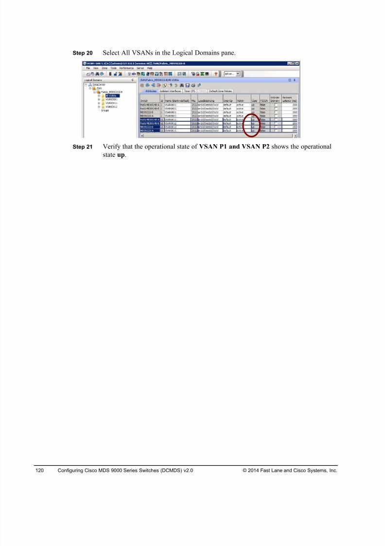
8/18/2019 FL_DCMDS_2.0.3_LG(1).pdf
http://slidepdf.com/reader/full/fldcmds203lg1pdf 120/482
120 Configuring Cisco MDS 9000 Series Switches (DCMDS) v2.0 © 2014 Fast Lane and Cisco Systems, Inc.
Step 20 Select All VSANs in the Logical Domains pane.
Step 21 Verify that the operational state of VSAN P1 and VSAN P2 shows the operational
state up.
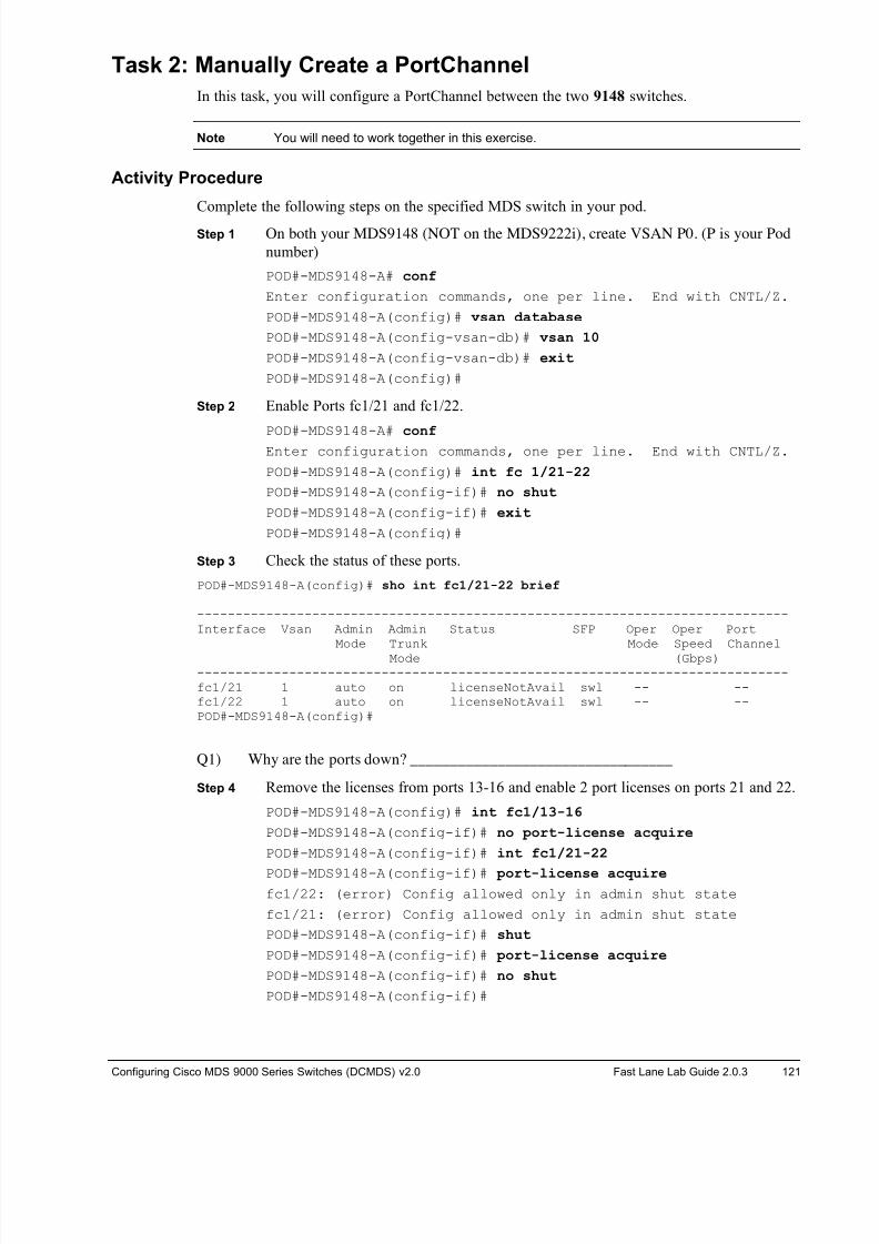
8/18/2019 FL_DCMDS_2.0.3_LG(1).pdf
http://slidepdf.com/reader/full/fldcmds203lg1pdf 121/482
Configuring Cisco MDS 9000 Series Switches (DCMDS) v2.0 Fast Lane Lab Guide 2.0.3 121
Task 2: Manually Create a PortChannel
In this task, you will configure a PortChannel between the two 9148 switches.
Note You will need to work together in this exercise.
Activity Procedure
Complete the following steps on the specified MDS switch in your pod.
Step 1 On both your MDS9148 (NOT on the MDS9222i), create VSAN P0. (P is your Pod
number)
POD#-MDS9148-A# conf
Enter configuration commands, one per line. End with CNTL/Z.
POD#-MDS9148-A(config)# vsan database
POD#-MDS9148-A(config-vsan-db)# vsan 10
POD#-MDS9148-A(config-vsan-db)# exit
POD#-MDS9148-A(config)#
Step 2 Enable Ports fc1/21 and fc1/22.
POD#-MDS9148-A# conf Enter configuration commands, one per line. End with CNTL/Z.
POD#-MDS9148-A(config)# int fc 1/21-22
POD#-MDS9148-A(config-if)# no shut
POD#-MDS9148-A(config-if)# exit
POD#-MDS9148-A(config)#
Step 3 Check the status of these ports.
POD#-MDS9148-A(config)# sho int fc1/21-22 brief
-----------------------------------------------------------------------------Interface Vsan Admin Admin Status SFP Oper Oper Port
Mode Trunk Mode Speed Channel
Mode (Gbps)-----------------------------------------------------------------------------fc1/21 1 auto on licenseNotAvail swl -- --fc1/22 1 auto on licenseNotAvail swl -- --POD#-MDS9148-A(config)#
Q1) Why are the ports down? _________________________________
Step 4 Remove the licenses from ports 13-16 and enable 2 port licenses on ports 21 and 22.
POD#-MDS9148-A(config)# int fc1/13-16
POD#-MDS9148-A(config-if)# no port-license acquire
POD#-MDS9148-A(config-if)# int fc1/21-22
POD#-MDS9148-A(config-if)# port-license acquire fc1/22: (error) Config allowed only in admin shut state
fc1/21: (error) Config allowed only in admin shut state
POD#-MDS9148-A(config-if)# shut
POD#-MDS9148-A(config-if)# port-license acquire
POD#-MDS9148-A(config-if)# no shut
POD#-MDS9148-A(config-if)#
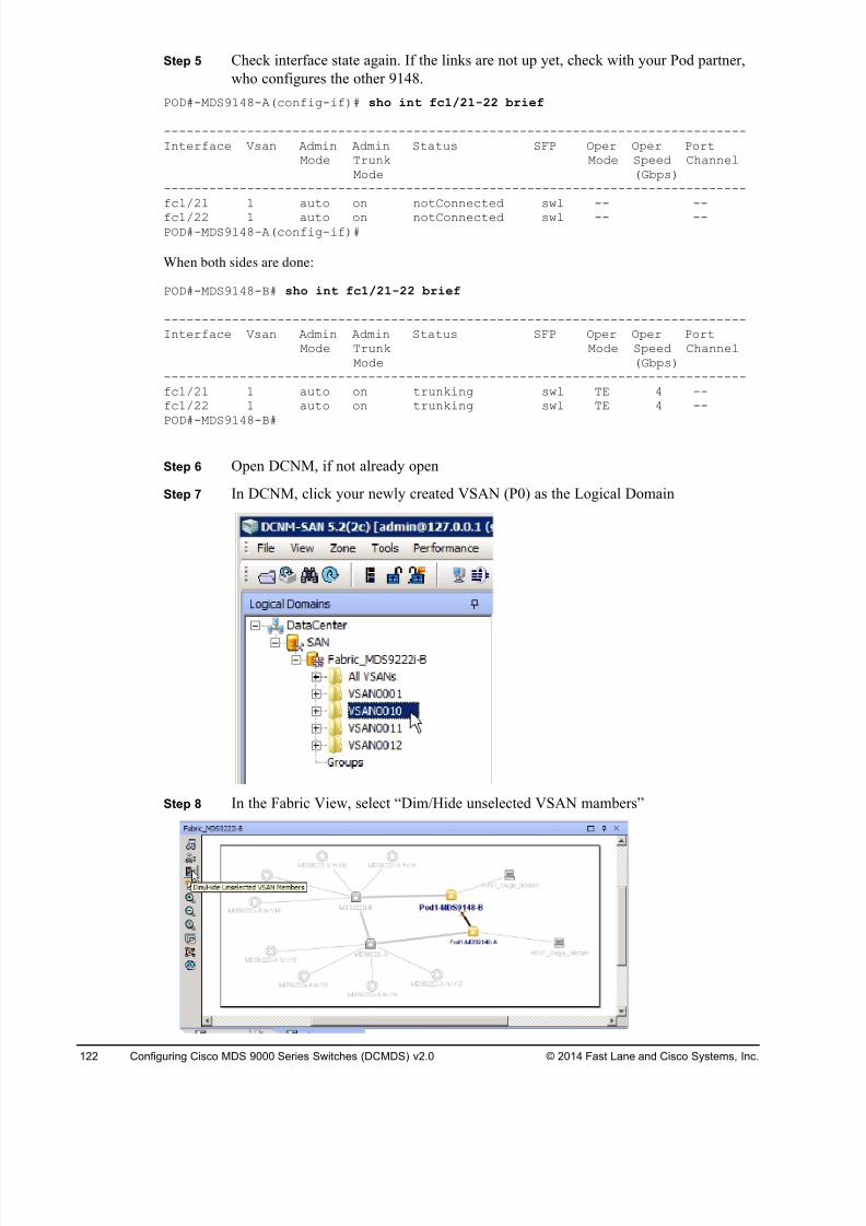
8/18/2019 FL_DCMDS_2.0.3_LG(1).pdf
http://slidepdf.com/reader/full/fldcmds203lg1pdf 122/482
122 Configuring Cisco MDS 9000 Series Switches (DCMDS) v2.0 © 2014 Fast Lane and Cisco Systems, Inc.
Step 5 Check interface state again. If the links are not up yet, check with your Pod partner,
who configures the other 9148.
POD#-MDS9148-A(config-if)# sho int fc1/21-22 brief
-----------------------------------------------------------------------------Interface Vsan Admin Admin Status SFP Oper Oper Port
Mode Trunk Mode Speed ChannelMode (Gbps)
-----------------------------------------------------------------------------fc1/21 1 auto on notConnected swl -- --
fc1/22 1 auto on notConnected swl -- --POD#-MDS9148-A(config-if)#
When both sides are done:
POD#-MDS9148-B# sho int fc1/21-22 brief
-----------------------------------------------------------------------------Interface Vsan Admin Admin Status SFP Oper Oper Port
Mode Trunk Mode Speed ChannelMode (Gbps)
-----------------------------------------------------------------------------fc1/21 1 auto on trunking swl TE 4 --fc1/22 1 auto on trunking swl TE 4 --POD#-MDS9148-B#
Step 6 Open DCNM, if not already open
Step 7 In DCNM, click your newly created VSAN (P0) as the Logical Domain
Step 8 In the Fabric View, select “Dim/Hide unselected VSAN mambers”
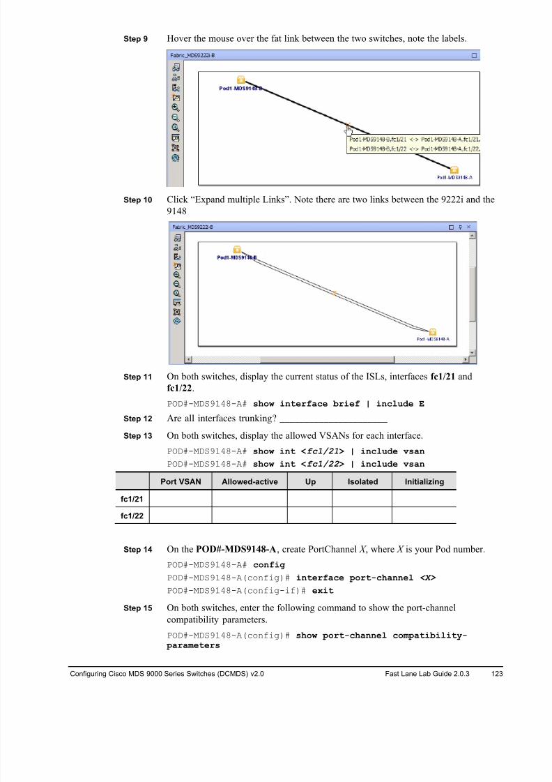
8/18/2019 FL_DCMDS_2.0.3_LG(1).pdf
http://slidepdf.com/reader/full/fldcmds203lg1pdf 123/482
Configuring Cisco MDS 9000 Series Switches (DCMDS) v2.0 Fast Lane Lab Guide 2.0.3 123
Step 9 Hover the mouse over the fat link between the two switches, note the labels.
Step 10 Click “Expand multiple Links”. Note there are two links between the 9222i and the
9148
Step 11 On both switches, display the current status of the ISLs, interfaces fc1/21 and
fc1/22.
POD#-MDS9148-A# show interface brief | include E
Step 12 Are all interfaces trunking? ______________________
Step 13 On both switches, display the allowed VSANs for each interface.
POD#-MDS9148-A# show int <fc1/21> | include vsan
POD#-MDS9148-A# show int <fc1/22 > | include vsan
Port VSAN Allowed-active Up Isolated Initializing
fc1/21
fc1/22
Step 14 On the POD#-MDS9148-A, create PortChannel X , where X is your Pod number.
POD#-MDS9148-A# config
POD#-MDS9148-A(config)# interface port-channel <X>
POD#-MDS9148-A(config-if)# exit
Step 15 On both switches, enter the following command to show the port-channel
compatibility parameters.
POD#-MDS9148-A(config)# show port-channel compatibility- parameters
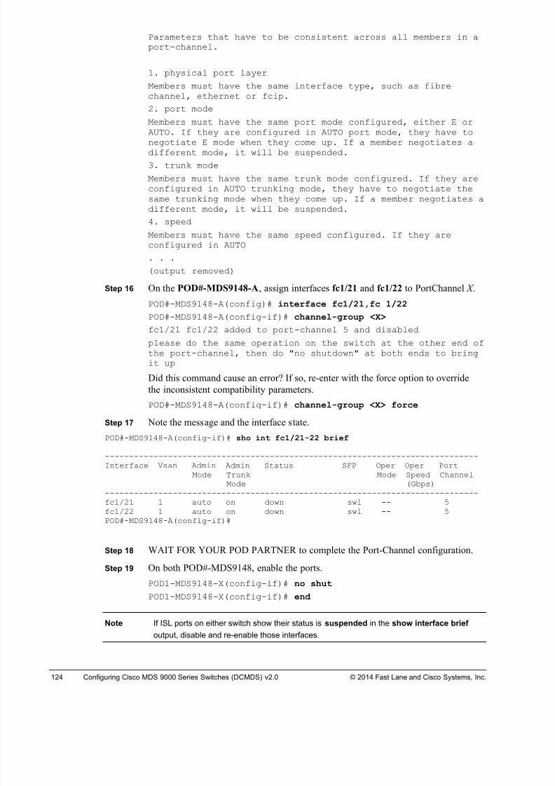
8/18/2019 FL_DCMDS_2.0.3_LG(1).pdf
http://slidepdf.com/reader/full/fldcmds203lg1pdf 124/482
124 Configuring Cisco MDS 9000 Series Switches (DCMDS) v2.0 © 2014 Fast Lane and Cisco Systems, Inc.
Parameters that have to be consistent across all members in aport-channel.
1. physical port layer
Members must have the same interface type, such as fibrechannel, ethernet or fcip.
2. port mode
Members must have the same port mode configured, either E orAUTO. If they are configured in AUTO port mode, they have tonegotiate E mode when they come up. If a member negotiates adifferent mode, it will be suspended.
3. trunk mode
Members must have the same trunk mode configured. If they areconfigured in AUTO trunking mode, they have to negotiate thesame trunking mode when they come up. If a member negotiates adifferent mode, it will be suspended.
4. speed
Members must have the same speed configured. If they areconfigured in AUTO
. . .
(output removed)Step 16 On the POD#-MDS9148-A, assign interfaces fc1/21 and fc1/22 to PortChannel X .
POD#-MDS9148-A(config)# interface fc1/21,fc 1/22
POD#-MDS9148-A(config-if)# channel-group <X>
fc1/21 fc1/22 added to port-channel 5 and disabled
please do the same operation on the switch at the other end ofthe port-channel, then do "no shutdown" at both ends to bringit up
Did this command cause an error? If so, re-enter with the force option to override
the inconsistent compatibility parameters.
POD#-MDS9148-A(config-if)# channel-group <X> force
Step 17 Note the message and the interface state.
POD#-MDS9148-A(config-if)# sho int fc1/21-22 brief
-----------------------------------------------------------------------------Interface Vsan Admin Admin Status SFP Oper Oper Port
Mode Trunk Mode Speed ChannelMode (Gbps)
-----------------------------------------------------------------------------fc1/21 1 auto on down swl -- 5fc1/22 1 auto on down swl -- 5POD#-MDS9148-A(config-if)#
Step 18 WAIT FOR YOUR POD PARTNER to complete the Port-Channel configuration.
Step 19 On both POD#-MDS9148, enable the ports.
POD1-MDS9148-X(config-if)# no shut
POD1-MDS9148-X(config-if)# end
Note If ISL ports on either switch show their status is suspended in the show interface brief
output, disable and re-enable those interfaces.
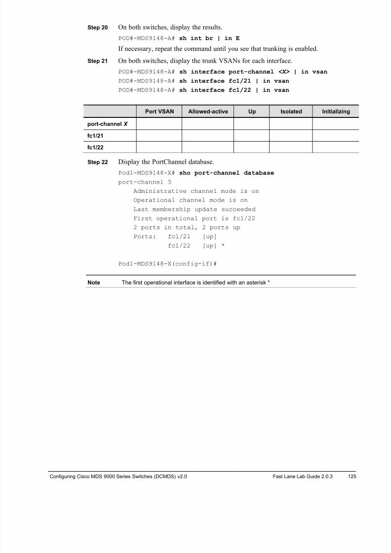
8/18/2019 FL_DCMDS_2.0.3_LG(1).pdf
http://slidepdf.com/reader/full/fldcmds203lg1pdf 125/482
Configuring Cisco MDS 9000 Series Switches (DCMDS) v2.0 Fast Lane Lab Guide 2.0.3 125
Step 20 On both switches, display the results.
POD#-MDS9148-A# sh int br | in E
If necessary, repeat the command until you see that trunking is enabled.
Step 21 On both switches, display the trunk VSANs for each interface.
POD#-MDS9148-A# sh interface port-channel <X> | in vsan
POD#-MDS9148-A# sh interface fc1/21 | in vsan
POD#-MDS9148-A# sh interface fc1/22 | in vsan
Port VSAN Allowed-active Up Isolated Initializing
port-channel X
fc1/21
fc1/22
Step 22 Display the PortChannel database.
Pod1-MDS9148-X# sho port-channel database
port-channel 5
Administrative channel mode is onOperational channel mode is on
Last membership update succeeded
First operational port is fc1/22
2 ports in total, 2 ports up
Ports: fc1/21 [up]
fc1/22 [up] *
Pod1-MDS9148-X(config-if)#
Note The first operational interface is identified with an asterisk *
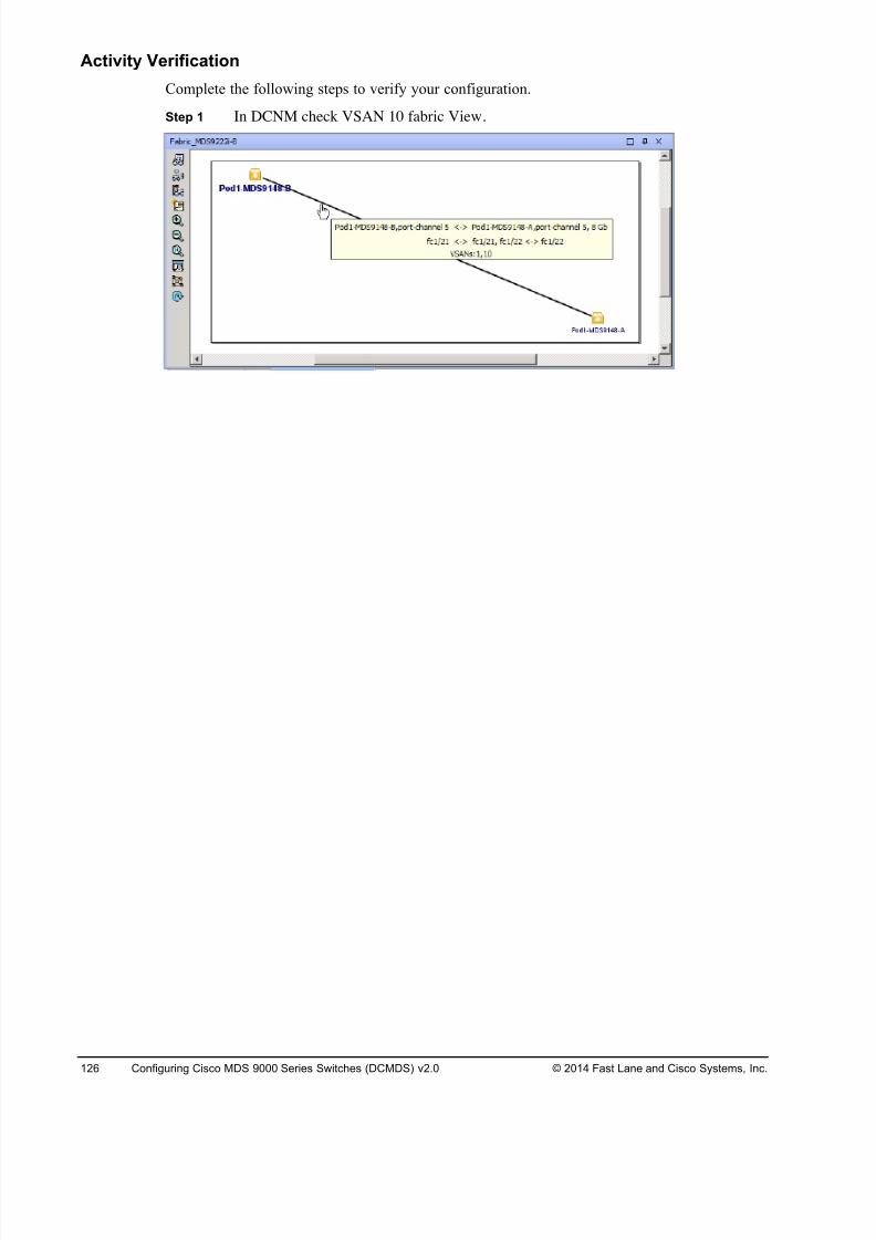
8/18/2019 FL_DCMDS_2.0.3_LG(1).pdf
http://slidepdf.com/reader/full/fldcmds203lg1pdf 126/482
126 Configuring Cisco MDS 9000 Series Switches (DCMDS) v2.0 © 2014 Fast Lane and Cisco Systems, Inc.
Activity Verification
Complete the following steps to verify your configuration.
Step 1 In DCNM check VSAN 10 fabric View.
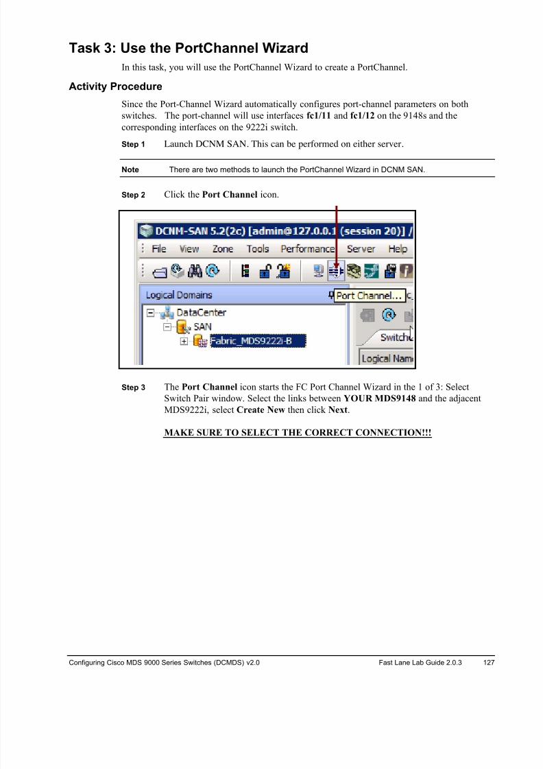
8/18/2019 FL_DCMDS_2.0.3_LG(1).pdf
http://slidepdf.com/reader/full/fldcmds203lg1pdf 127/482
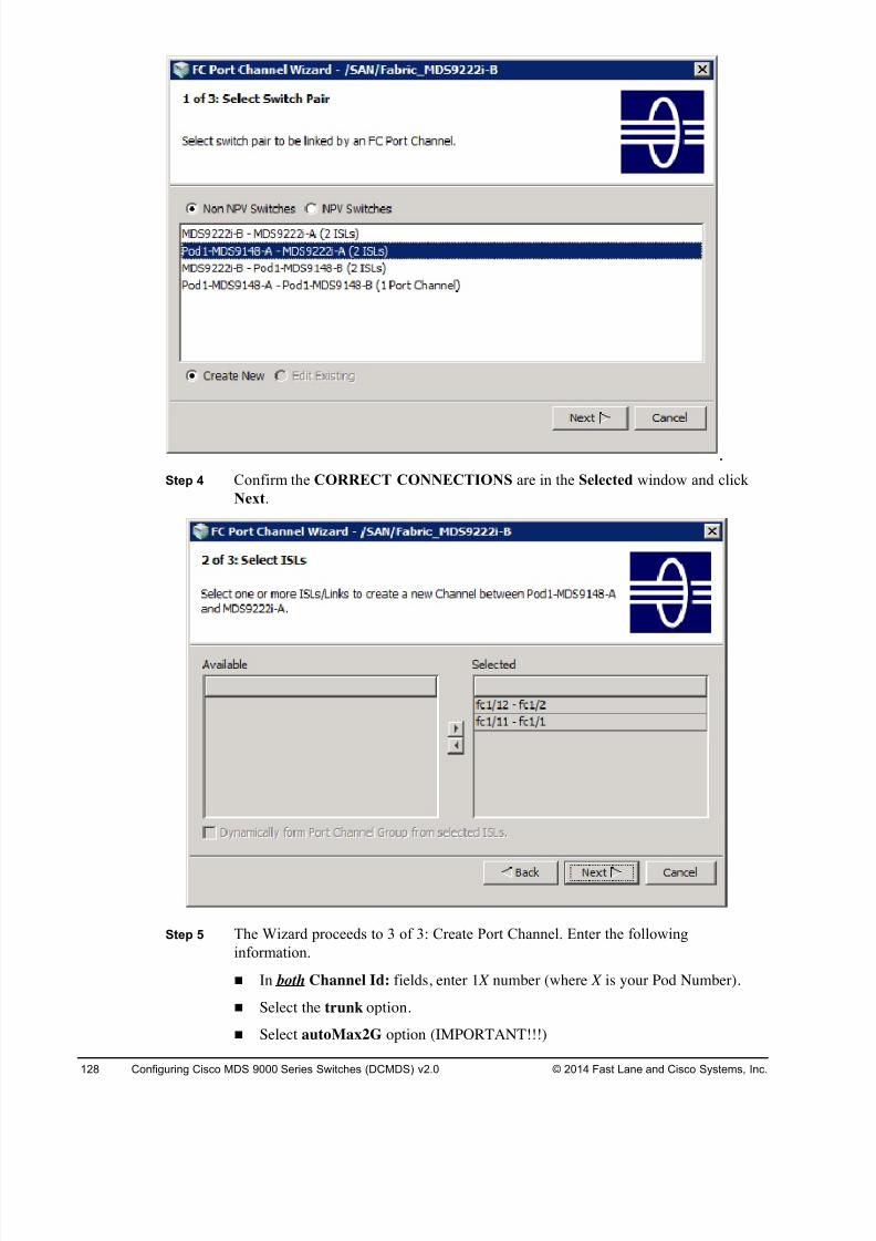
8/18/2019 FL_DCMDS_2.0.3_LG(1).pdf
http://slidepdf.com/reader/full/fldcmds203lg1pdf 128/482
128 Configuring Cisco MDS 9000 Series Switches (DCMDS) v2.0 © 2014 Fast Lane and Cisco Systems, Inc.
Step 4 Confirm the CORRECT CONNECTIONS are in the Selected window and click
Next.
Step 5 The Wizard proceeds to 3 of 3: Create Port Channel. Enter the following
information.
! In both Channel Id: fields, enter 1 X number (where X is your Pod Number).
! Select the trunk option.
! Select autoMax2G option (IMPORTANT!!!)
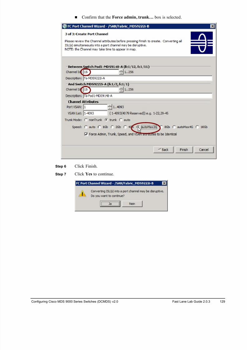
8/18/2019 FL_DCMDS_2.0.3_LG(1).pdf
http://slidepdf.com/reader/full/fldcmds203lg1pdf 129/482
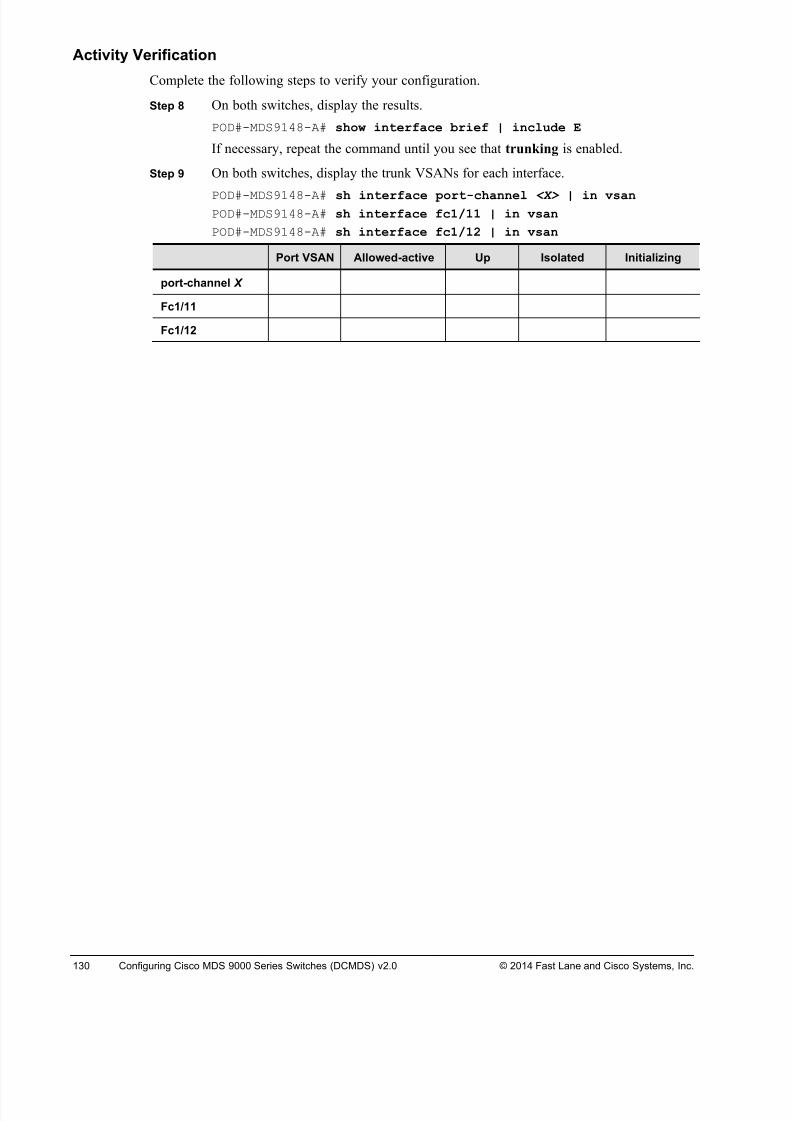
8/18/2019 FL_DCMDS_2.0.3_LG(1).pdf
http://slidepdf.com/reader/full/fldcmds203lg1pdf 130/482
130 Configuring Cisco MDS 9000 Series Switches (DCMDS) v2.0 © 2014 Fast Lane and Cisco Systems, Inc.
Activity Verification
Complete the following steps to verify your configuration.
Step 8 On both switches, display the results.
POD#-MDS9148-A# show interface brief | include E
If necessary, repeat the command until you see that trunking is enabled.
Step 9 On both switches, display the trunk VSANs for each interface.
POD#-MDS9148-A# sh interface port-channel <X> | in vsanPOD#-MDS9148-A# sh interface fc1/11 | in vsan
POD#-MDS9148-A# sh interface fc1/12 | in vsan
Port VSAN Allowed-active Up Isolated Initializing
port-channel X
Fc1/11
Fc1/12
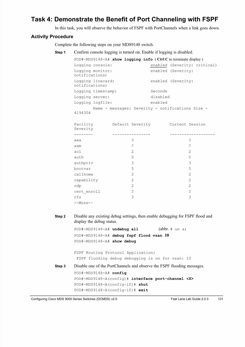
8/18/2019 FL_DCMDS_2.0.3_LG(1).pdf
http://slidepdf.com/reader/full/fldcmds203lg1pdf 131/482
Configuring Cisco MDS 9000 Series Switches (DCMDS) v2.0 Fast Lane Lab Guide 2.0.3 131
Task 4: Demonstrate the Benefit of Port Channeling with FSPF
In this task, you will observe the behavior of FSPF with PortChannels when a link goes down.
Activity Procedure
Complete the following steps on your MDS9148 switch.
Step 1 Confirm console logging is turned on. Enable if logging is disabled.
POD#-MDS9148-A# show logging info ( Ctrl C to terminate display )Logging console: enabled (Severity: critical)
Logging monitor: enabled (Severity:notifications)
Logging linecard: enabled (Severity:notifications)
Logging timestamp: Seconds
Logging server: disabled
Logging logfile: enabled
Name - messages: Severity - notifications Size -4194304
Facility Default Severity Current SessionSeverity
-------- ---------------- -------------------
aaa 3 3
aam 2 2
acl 2 2
auth 0 0
authpriv 3 3
bootvar 5 5
callhome 2 2
capability 2 2
cdp 2 2
cert_enroll 2 2
cfs 3 3
--More--
Step 2 Disable any existing debug settings, then enable debugging for FSPF flood and
display the debug status.
POD#-MDS9148-A# undebug all (abbr. # un a)
POD#-MDS9148-A# debug fspf flood vsan 10
POD#-MDS9148-A# show debug
FSPF Routing Protocol Application:
FSPF flooding debug debugging is on for vsan: 10
Step 3 Disable one of the PortChannels and observe the FSPF flooding messages.
POD#-MDS9148-A# config
POD#-MDS9148-A(config)# interface port-channel <X>
POD#-MDS9148-A(config-if)# shut
POD#-MDS9148-A(config-if)# exit
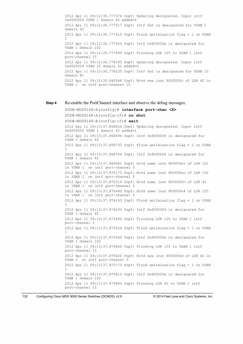
8/18/2019 FL_DCMDS_2.0.3_LG(1).pdf
http://slidepdf.com/reader/full/fldcmds203lg1pdf 132/482
132 Configuring Cisco MDS 9000 Series Switches (DCMDS) v2.0 © 2014 Fast Lane and Cisco Systems, Inc.
2012 Apr 11 09:12:30.777374 fspf: Updating designated. Input intf0x4000004 VSAN 1 domain 42 added=0
2012 Apr 11 09:12:30.777517 fspf: Intf 0x0 is designated for VSAN 1domain 42
2012 Apr 11 09:12:30.777610 fspf: Flood optimisation flag = 1 on VSAN1
2012 Apr 11 09:12:30.777650 fspf: Intf 0x400000e is designated forVSAN 1 domain 102
2012 Apr 11 09:12:30.777699 fspf: Flooding LSR 125 to VSAN 1 intfport-channel 15
2012 Apr 11 09:12:30.778185 fspf: Updating designated. Input intf0x4000004 VSAN 10 domain 81 added=0
2012 Apr 11 09:12:30.778235 fspf: Intf 0x0 is designated for VSAN 10domain 81
2012 Apr 11 09:12:30.845548 fspf: Rcvd new inst 8000000c of LSR 42 inVSAN 1 on intf port-channel 15
Step 4 Re-enable the PortChannel interface and observe the debug messages.
POD#-MDS9148-A(config)# interface port-chan <X>
POD#-MDS9148-A(config-if)# no shut
POD#-MDS9148-A(config-if)# exit 2012 Apr 11 09:13:37.868624 fspf: Updating designated. Input intf0x4000004 VSAN 1 domain 42 added=1
2012 Apr 11 09:13:37.868694 fspf: Intf 0x4000004 is designated forVSAN 1 domain 42
2012 Apr 11 09:13:37.868732 fspf: Flood optimisation flag = 1 on VSAN1
2012 Apr 11 09:13:37.868769 fspf: Intf 0x4000004 is designated forVSAN 1 domain 42
2012 Apr 11 09:13:37.869981 fspf: Rcvd same inst 800000e1 of LSR 101in VSAN 1 on intf port-channel 5
2012 Apr 11 09:13:37.870175 fspf: Rcvd same inst 800000ec of LSR 102in VSAN 1 on intf port-channel 5
2012 Apr 11 09:13:37.870314 fspf: Rcvd same inst 8000000c of LSR 42in VSAN 1 on intf port-channel 5
2012 Apr 11 09:13:37.870449 fspf: Rcvd same inst 800000e4 of LSR 125in VSAN 1 on intf port-channel 5
2012 Apr 11 09:13:37.874163 fspf: Flood optimisation flag = 1 on VSAN1
2012 Apr 11 09:13:37.874235 fspf: Intf 0x4000004 is designated forVSAN 1 domain 42
2012 Apr 11 09:13:37.874286 fspf: Flooding LSR 125 to VSAN 1 intfport-channel 5
2012 Apr 11 09:13:37.874324 fspf: Flood optimisation flag = 1 on VSAN1
2012 Apr 11 09:13:37.874360 fspf: Intf 0x400000e is designated for
VSAN 1 domain 1022012 Apr 11 09:13:37.874406 fspf: Flooding LSR 125 to VSAN 1 intfport-channel 15
2012 Apr 11 09:13:37.875620 fspf: Rcvd new inst 8000000d of LSR 42 inVSAN 1 on intf port-channel 5
2012 Apr 11 09:13:37.875773 fspf: Flood optimisation flag = 1 on VSAN1
2012 Apr 11 09:13:37.875815 fspf: Intf 0x400000e is designated forVSAN 1 domain 102
2012 Apr 11 09:13:37.875860 fspf: Flooding LSR 42 to VSAN 1 intfport-channel 15
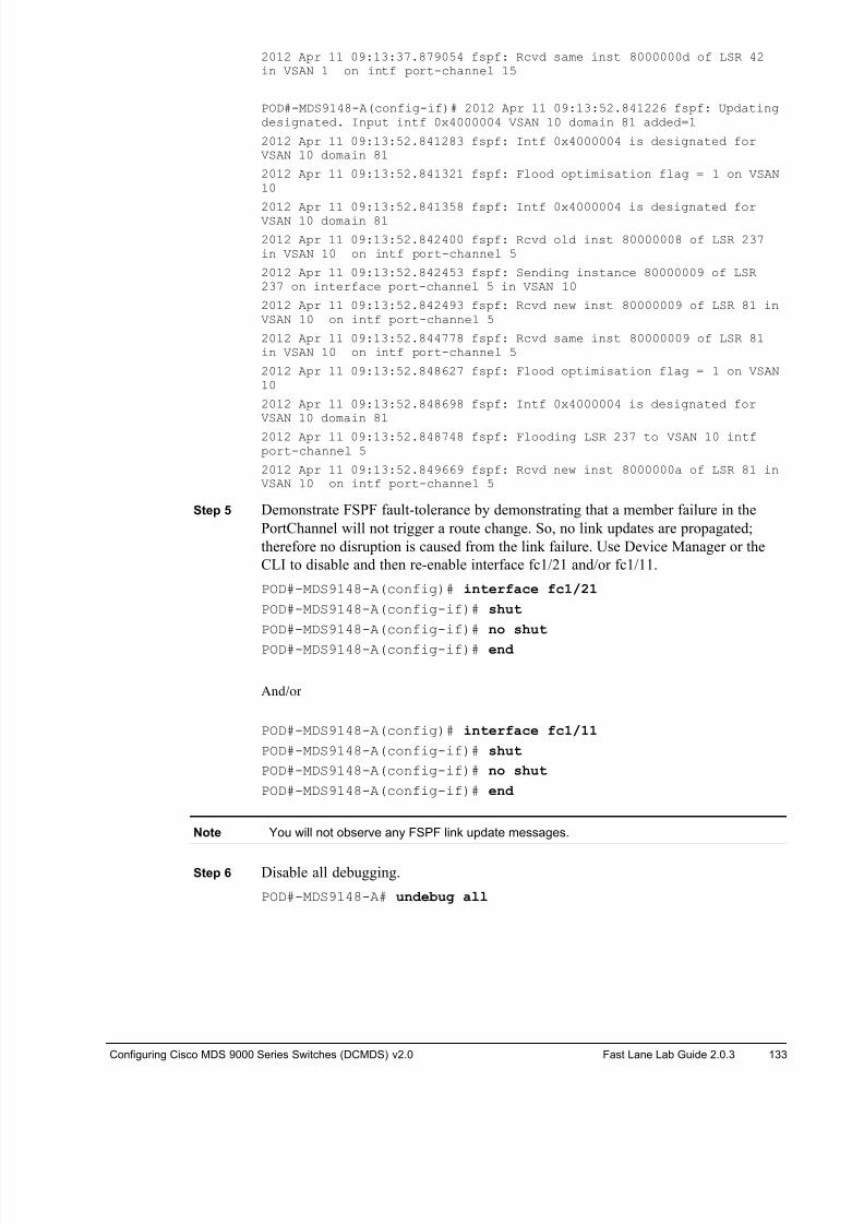
8/18/2019 FL_DCMDS_2.0.3_LG(1).pdf
http://slidepdf.com/reader/full/fldcmds203lg1pdf 133/482
Configuring Cisco MDS 9000 Series Switches (DCMDS) v2.0 Fast Lane Lab Guide 2.0.3 133
2012 Apr 11 09:13:37.879054 fspf: Rcvd same inst 8000000d of LSR 42in VSAN 1 on intf port-channel 15
POD#-MDS9148-A(config-if)# 2012 Apr 11 09:13:52.841226 fspf: Updatingdesignated. Input intf 0x4000004 VSAN 10 domain 81 added=1
2012 Apr 11 09:13:52.841283 fspf: Intf 0x4000004 is designated forVSAN 10 domain 81
2012 Apr 11 09:13:52.841321 fspf: Flood optimisation flag = 1 on VSAN10
2012 Apr 11 09:13:52.841358 fspf: Intf 0x4000004 is designated forVSAN 10 domain 81
2012 Apr 11 09:13:52.842400 fspf: Rcvd old inst 80000008 of LSR 237in VSAN 10 on intf port-channel 5
2012 Apr 11 09:13:52.842453 fspf: Sending instance 80000009 of LSR237 on interface port-channel 5 in VSAN 10
2012 Apr 11 09:13:52.842493 fspf: Rcvd new inst 80000009 of LSR 81 inVSAN 10 on intf port-channel 5
2012 Apr 11 09:13:52.844778 fspf: Rcvd same inst 80000009 of LSR 81in VSAN 10 on intf port-channel 5
2012 Apr 11 09:13:52.848627 fspf: Flood optimisation flag = 1 on VSAN10
2012 Apr 11 09:13:52.848698 fspf: Intf 0x4000004 is designated forVSAN 10 domain 81
2012 Apr 11 09:13:52.848748 fspf: Flooding LSR 237 to VSAN 10 intfport-channel 5
2012 Apr 11 09:13:52.849669 fspf: Rcvd new inst 8000000a of LSR 81 inVSAN 10 on intf port-channel 5
Step 5 Demonstrate FSPF fault-tolerance by demonstrating that a member failure in the
PortChannel will not trigger a route change. So, no link updates are propagated;
therefore no disruption is caused from the link failure. Use Device Manager or the
CLI to disable and then re-enable interface fc1/21 and/or fc1/11.
POD#-MDS9148-A(config)# interface fc1/21
POD#-MDS9148-A(config-if)# shut
POD#-MDS9148-A(config-if)# no shut
POD#-MDS9148-A(config-if)# end
And/or
POD#-MDS9148-A(config)# interface fc1/11
POD#-MDS9148-A(config-if)# shut
POD#-MDS9148-A(config-if)# no shut
POD#-MDS9148-A(config-if)# end
Note You will not observe any FSPF link update messages.
Step 6 Disable all debugging.
POD#-MDS9148-A# undebug all
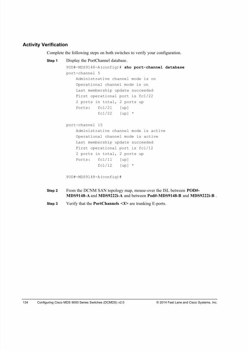
8/18/2019 FL_DCMDS_2.0.3_LG(1).pdf
http://slidepdf.com/reader/full/fldcmds203lg1pdf 134/482
134 Configuring Cisco MDS 9000 Series Switches (DCMDS) v2.0 © 2014 Fast Lane and Cisco Systems, Inc.
Activity Verification
Complete the following steps on both switches to verify your configuration.
Step 1 Display the PortChannel database.POD#-MDS9148-A(config)# sho port-channel database
port-channel 5
Administrative channel mode is on
Operational channel mode is on
Last membership update succeeded
First operational port is fc1/22
2 ports in total, 2 ports up
Ports: fc1/21 [up]
fc1/22 [up] *
port-channel 15
Administrative channel mode is active
Operational channel mode is active
Last membership update succeeded
First operational port is fc1/12
2 ports in total, 2 ports up
Ports: fc1/11 [up]
fc1/12 [up] *
POD#-MDS9148-A(config)#
Step 2 From the DCNM SAN topology map, mouse-over the ISL between POD#-
MDS9148-A and MDS9222i-A and between Pod#-MDS9148-B and MDS9222i-B .
Step 3 Verify that the PortChannels <X> are trunking E-ports.
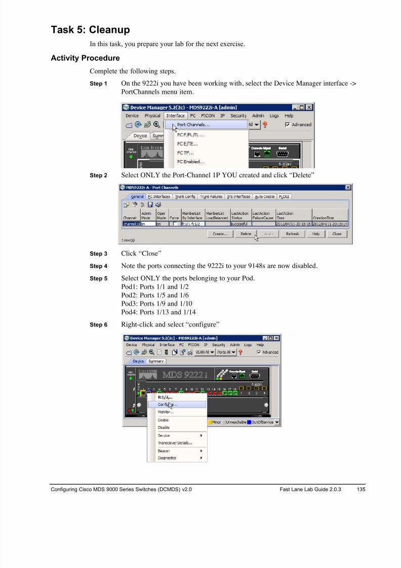
8/18/2019 FL_DCMDS_2.0.3_LG(1).pdf
http://slidepdf.com/reader/full/fldcmds203lg1pdf 135/482
Configuring Cisco MDS 9000 Series Switches (DCMDS) v2.0 Fast Lane Lab Guide 2.0.3 135
Task 5: Cleanup
In this task, you prepare your lab for the next exercise.
Activity Procedure
Complete the following steps.
Step 1 On the 9222i you have been working with, select the Device Manager interface ->
PortChannels menu item.
Step 2 Select ONLY the Port-Channel 1P YOU created and click “Delete”
Step 3 Click “Close”
Step 4 Note the ports connecting the 9222i to your 9148s are now disabled.
Step 5 Select ONLY the ports belonging to your Pod.
Pod1: Ports 1/1 and 1/2
Pod2: Ports 1/5 and 1/6Pod3: Ports 1/9 and 1/10
Pod4: Ports 1/13 and 1/14
Step 6 Right-click and select “configure”
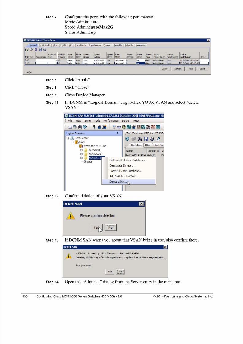
8/18/2019 FL_DCMDS_2.0.3_LG(1).pdf
http://slidepdf.com/reader/full/fldcmds203lg1pdf 136/482
136 Configuring Cisco MDS 9000 Series Switches (DCMDS) v2.0 © 2014 Fast Lane and Cisco Systems, Inc.
Step 7 Configure the ports with the following parameters:
Mode Admin: auto
Speed Admin: autoMax2G
Status Admin: up
Step 8 Click “Apply”
Step 9 Click “Close”
Step 10 Close Device Manager
Step 11 In DCNM in “Logical Domain”, right-click YOUR VSAN and select “delete
VSAN”
Step 12 Confirm deletion of your VSAN
Step 13 If DCNM SAN warns you about that VSAN being in use, also confirm there.
Step 14 Open the “Admin…” dialog from the Server entry in the menu bar
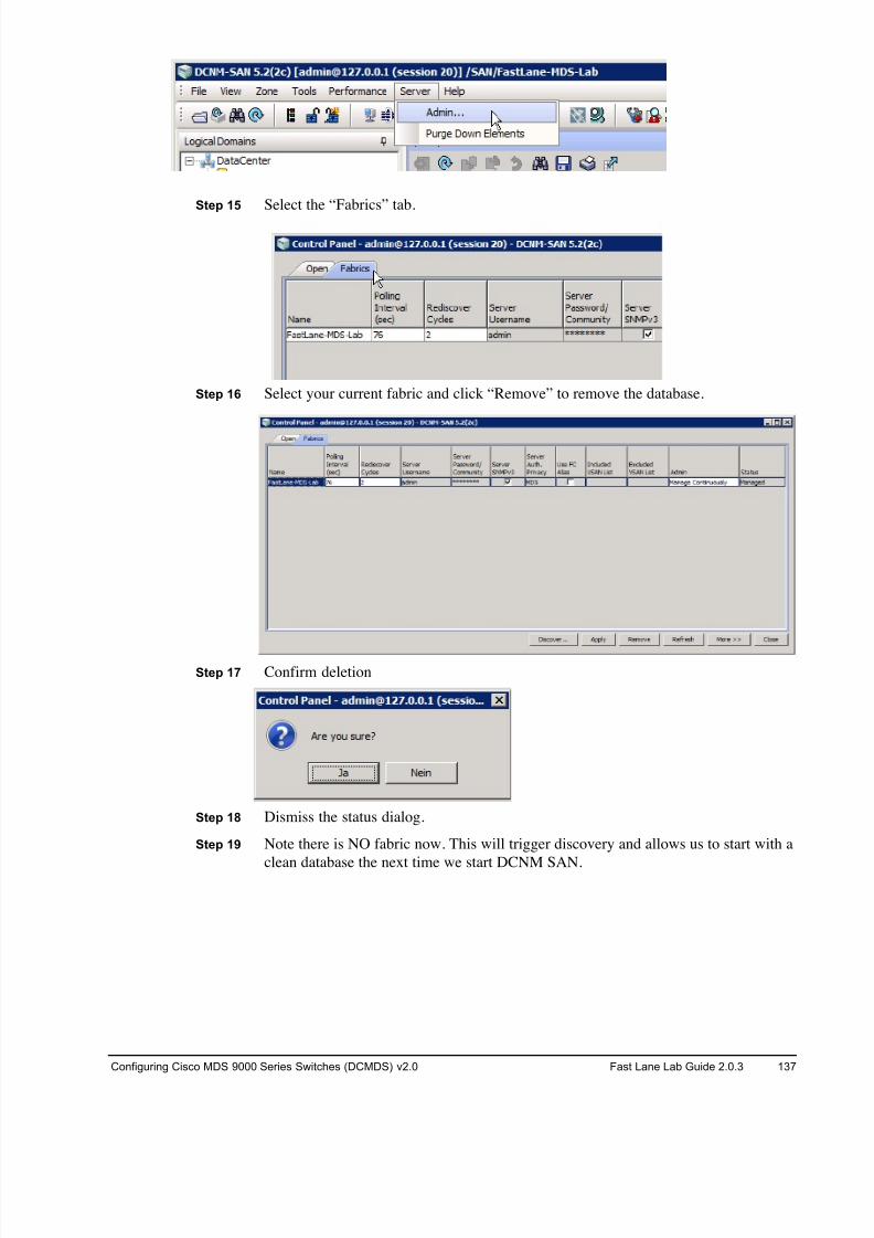
8/18/2019 FL_DCMDS_2.0.3_LG(1).pdf
http://slidepdf.com/reader/full/fldcmds203lg1pdf 137/482
Configuring Cisco MDS 9000 Series Switches (DCMDS) v2.0 Fast Lane Lab Guide 2.0.3 137
Step 15 Select the “Fabrics” tab.
Step 16 Select your current fabric and click “Remove” to remove the database.
Step 17 Confirm deletion
Step 18 Dismiss the status dialog.
Step 19 Note there is NO fabric now. This will trigger discovery and allows us to start with a
clean database the next time we start DCNM SAN.
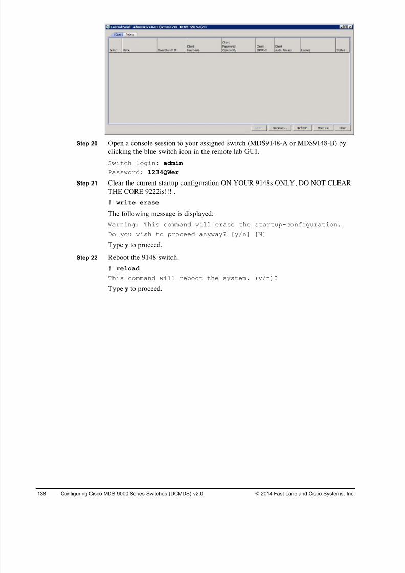
8/18/2019 FL_DCMDS_2.0.3_LG(1).pdf
http://slidepdf.com/reader/full/fldcmds203lg1pdf 138/482
138 Configuring Cisco MDS 9000 Series Switches (DCMDS) v2.0 © 2014 Fast Lane and Cisco Systems, Inc.
Step 20 Open a console session to your assigned switch (MDS9148-A or MDS9148-B) by
clicking the blue switch icon in the remote lab GUI.
Switch login: admin
Password: 1234QWer
Step 21 Clear the current startup configuration ON YOUR 9148s ONLY, DO NOT CLEAR
THE CORE 9222is!!! .
# write erase
The following message is displayed:
Warning: This command will erase the startup-configuration.
Do you wish to proceed anyway? [y/n] [N]
Type y to proceed.
Step 22 Reboot the 9148 switch.
# reload
This command will reboot the system. (y/n)?
Type y to proceed.
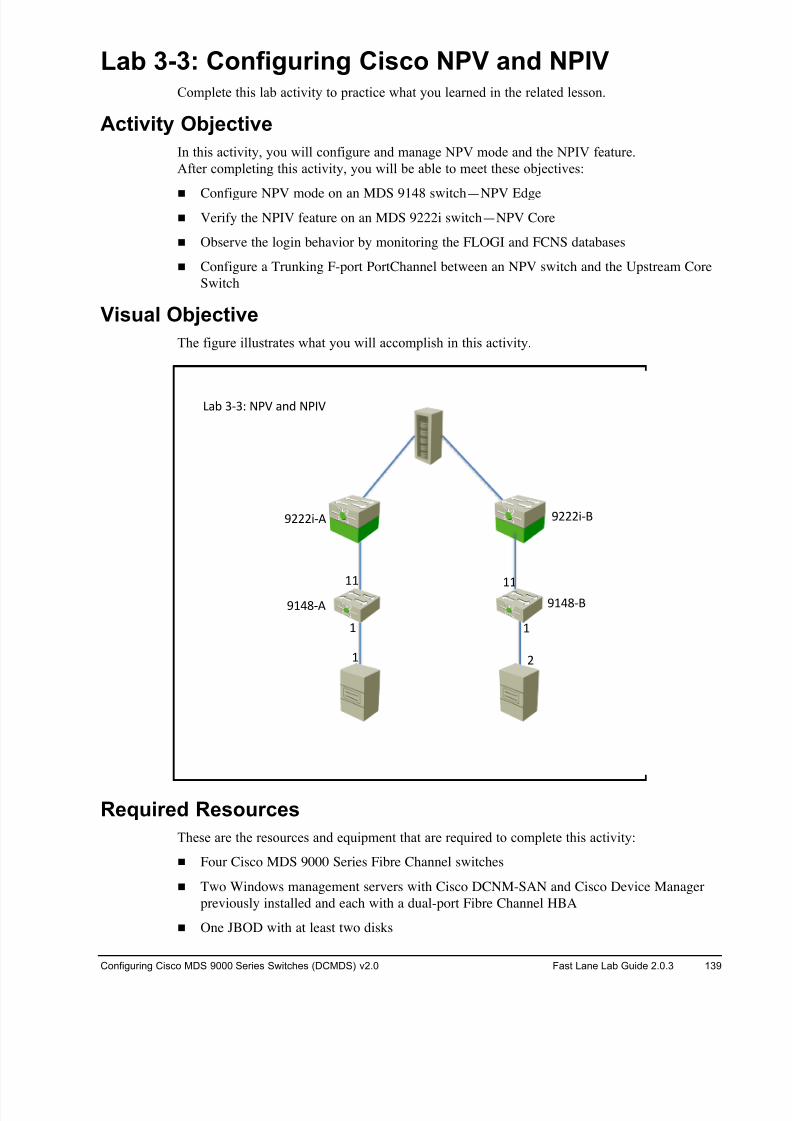
8/18/2019 FL_DCMDS_2.0.3_LG(1).pdf
http://slidepdf.com/reader/full/fldcmds203lg1pdf 139/482
Configuring Cisco MDS 9000 Series Switches (DCMDS) v2.0 Fast Lane Lab Guide 2.0.3 139
Lab 3-3: Configuring Cisco NPV and NPIV Complete this lab activity to practice what you learned in the related lesson.
Activity Objective
In this activity, you will configure and manage NPV mode and the NPIV feature.
After completing this activity, you will be able to meet these objectives:
! Configure NPV mode on an MDS 9148 switch—NPV Edge
! Verify the NPIV feature on an MDS 9222i switch—NPV Core
! Observe the login behavior by monitoring the FLOGI and FCNS databases
! Configure a Trunking F-port PortChannel between an NPV switch and the Upstream Core
Switch
Visual Objective
The figure illustrates what you will accomplish in this activity.
Required Resources
These are the resources and equipment that are required to complete this activity:
! Four Cisco MDS 9000 Series Fibre Channel switches
! Two Windows management servers with Cisco DCNM-SAN and Cisco Device Manager
previously installed and each with a dual-port Fibre Channel HBA
! One JBOD with at least two disks
! !
!!!!
! #
$!%&'( $!%&')
$###*'( $###*')
+,- .'./ 012 ,34 0152
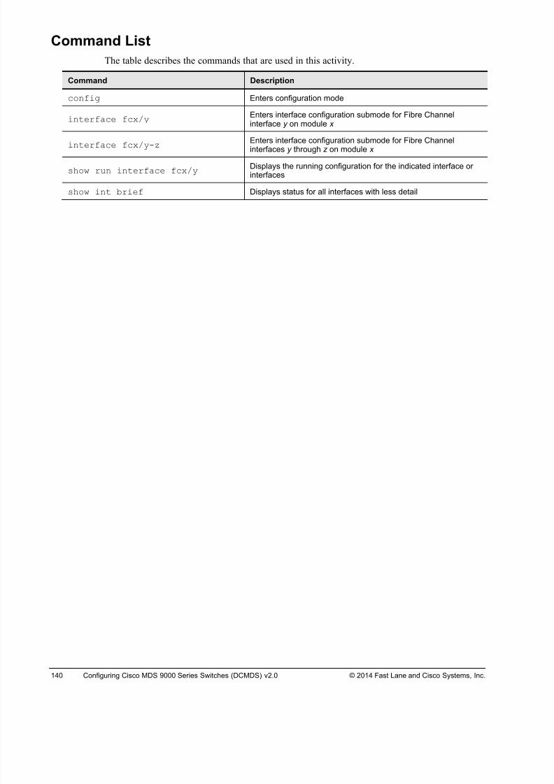
8/18/2019 FL_DCMDS_2.0.3_LG(1).pdf
http://slidepdf.com/reader/full/fldcmds203lg1pdf 140/482
140 Configuring Cisco MDS 9000 Series Switches (DCMDS) v2.0 © 2014 Fast Lane and Cisco Systems, Inc.
Command List
The table describes the commands that are used in this activity.
Command Description
config Enters configuration mode
interface fcx/yEnters interface configuration submode for Fibre Channelinterface y on module x
interface fcx/y-zEnters interface configuration submode for Fibre Channelinterfaces y through z on module x
show run interface fcx/yDisplays the running configuration for the indicated interface orinterfaces
show int brief Displays status for all interfaces with less detail
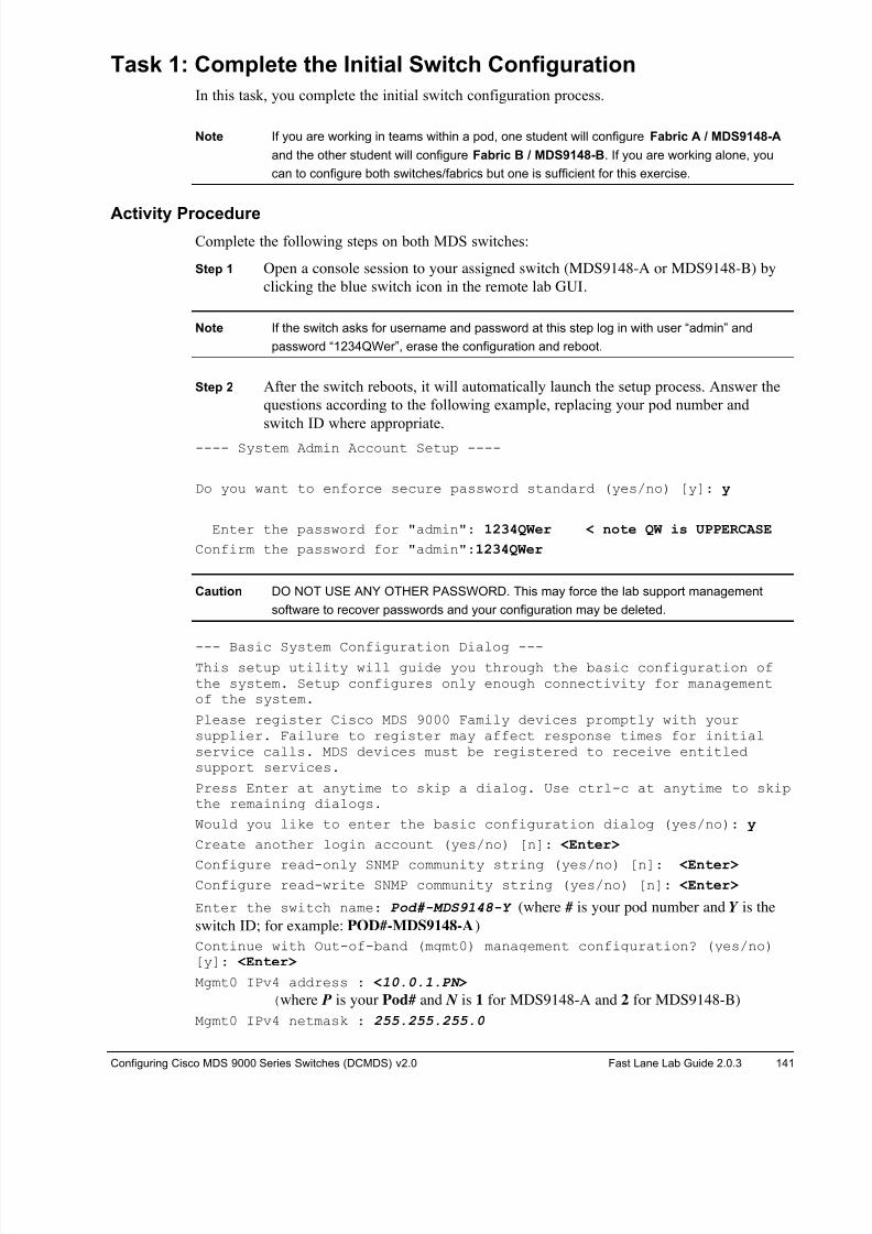
8/18/2019 FL_DCMDS_2.0.3_LG(1).pdf
http://slidepdf.com/reader/full/fldcmds203lg1pdf 141/482
Configuring Cisco MDS 9000 Series Switches (DCMDS) v2.0 Fast Lane Lab Guide 2.0.3 141
Task 1: Complete the Initial Switch Configuration
In this task, you complete the initial switch configuration process.
Note If you are working in teams within a pod, one student will configure Fabric A / MDS9148-A
and the other student will configure Fabric B / MDS9148-B. If you are working alone, you
can to configure both switches/fabrics but one is sufficient for this exercise.
Activity ProcedureComplete the following steps on both MDS switches:
Step 1 Open a console session to your assigned switch (MDS9148-A or MDS9148-B) by
clicking the blue switch icon in the remote lab GUI.
Note If the switch asks for username and password at this step log in with user “admin” and
password “1234QWer”, erase the configuration and reboot.
Step 2 After the switch reboots, it will automatically launch the setup process. Answer the
questions according to the following example, replacing your pod number and
switch ID where appropriate.
---- System Admin Account Setup ----
Do you want to enforce secure password standard (yes/no) [y]: y
Enter the password for "admin": 1234QWer < note QW is UPPERCASE
Confirm the password for "admin":1234QWer
Caution DO NOT USE ANY OTHER PASSWORD. This may force the lab support management
software to recover passwords and your configuration may be deleted.
--- Basic System Configuration Dialog ---This setup utility will guide you through the basic configuration ofthe system. Setup configures only enough connectivity for managementof the system.
Please register Cisco MDS 9000 Family devices promptly with yoursupplier. Failure to register may affect response times for initialservice calls. MDS devices must be registered to receive entitledsupport services.
Press Enter at anytime to skip a dialog. Use ctrl-c at anytime to skipthe remaining dialogs.
Would you like to enter the basic configuration dialog (yes/no): y
Create another login account (yes/no) [n]: <Enter>
Configure read-only SNMP community string (yes/no) [n]: <Enter> Configure read-write SNMP community string (yes/no) [n]: <Enter>
Enter the switch name: Pod#-MDS9148-Y (where # is your pod number and Y is the
switch ID; for example: POD#-MDS9148-A)
Continue with Out-of-band (mgmt0) management configuration? (yes/no)[y]: <Enter>
Mgmt0 IPv4 address : <10.0.1.PN >
(where P is your Pod# and N is 1 for MDS9148-A and 2 for MDS9148-B)
Mgmt0 IPv4 netmask : 255.255.255.0

8/18/2019 FL_DCMDS_2.0.3_LG(1).pdf
http://slidepdf.com/reader/full/fldcmds203lg1pdf 142/482
142 Configuring Cisco MDS 9000 Series Switches (DCMDS) v2.0 © 2014 Fast Lane and Cisco Systems, Inc.
Configure the default gateway? (yes/no) [y]: <No>
Configure advanced IP options? (yes/no) [n]: <Enter>
Enable the ssh service? (yes/no) [y]: <No>
Enable the telnet service? (yes/no) [n]: <Yes>
Configure congestion/no_credit drop for fc interfaces? (yes/no)[y]: <Enter>
Enter the type of drop to configure congestion/no_credit drop?
(con/no) [c]: <Enter>Enter milliseconds in multiple of 10 for congestion-drop in range [100- 500], or [d/default] for default: <d>
Enter mode for congestion/no_credit drop[E/F]: <Enter>
Enable the http-server? (yes/no) [y]: <Enter>
Configure clock? (yes/no) [n]: <Enter>
Configure timezone? (yes/no) [n]: <Enter>
Configure summertime? (yes/no) [n]: <Enter>
Configure the ntp server? (yes/no) [n]: <Enter>
Configure default switchport interface state (shut/noshut) [shut]: <Enter>
Configure default switchport trunk mode (on/off/auto) [on]: <Enter> Configure default switchport port mode F (yes/no) [n]: <Enter>
Configure default zone policy (permit/deny) [deny]: <Enter>
Enable full zoneset distribution (yes/no) [n]: <Enter>
Configure default zone mode (basic/enhanced) [basic]: <Enter>
Step 3 A summary of the configuration will be displayed:
The following configuration will be applied:
password strength-check
switchname POD#-MDS9148-A
interface mgmt0
ip address 10.0.1.PN 255.255.255.0
no shutdown
no feature ssh
feature telnet
feature http-server
system default switchport shutdown
system default switchport trunk mode on
no system default zone default-zone permit
no system default zone distribute full
no system default zone mode enhanced
Step 4 Press Enter twice to save the configuration.
Would you like to edit the configuration? (yes/no) [n]: <Enter>
Use this configuration and save it? (yes/no) [y]: <Enter>
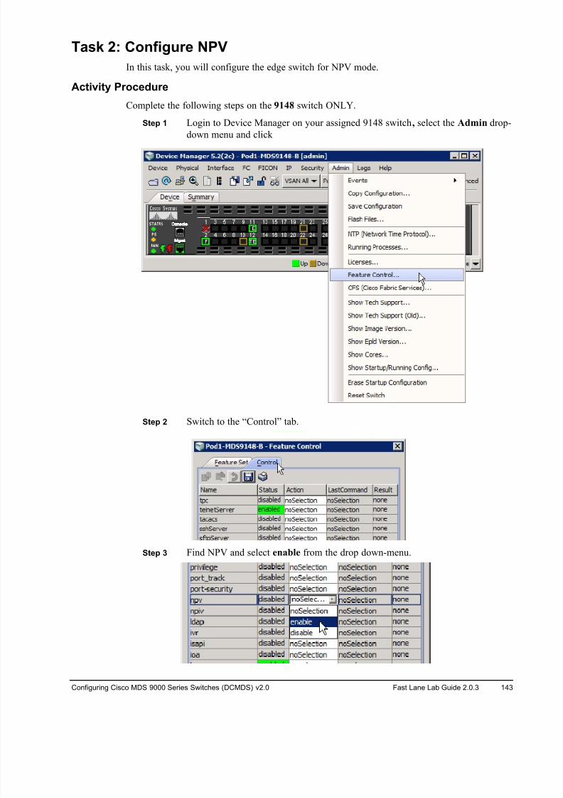
8/18/2019 FL_DCMDS_2.0.3_LG(1).pdf
http://slidepdf.com/reader/full/fldcmds203lg1pdf 143/482
Configuring Cisco MDS 9000 Series Switches (DCMDS) v2.0 Fast Lane Lab Guide 2.0.3 143
Task 2: Configure NPV
In this task, you will configure the edge switch for NPV mode.
Activity Procedure
Complete the following steps on the 9148 switch ONLY.
Step 1 Login to Device Manager on your assigned 9148 switch, select the Admin drop-
down menu and click
Step 2 Switch to the “Control” tab.
Step 3 Find NPV and select enable from the drop down-menu.
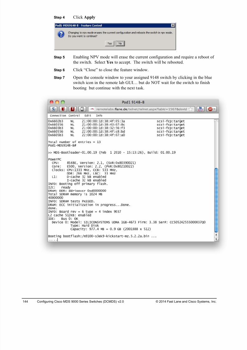
8/18/2019 FL_DCMDS_2.0.3_LG(1).pdf
http://slidepdf.com/reader/full/fldcmds203lg1pdf 144/482
144 Configuring Cisco MDS 9000 Series Switches (DCMDS) v2.0 © 2014 Fast Lane and Cisco Systems, Inc.
Step 4 Click Apply
Step 5 Enabling NPV mode will erase the current configuration and require a reboot of
the switch. Select Yes to accept. The switch will be rebooted.
Step 6 Click “Close” to close the feature window.
Step 7 Open the console window to your assigned 9148 switch by clicking in the blue
switch icon in the remote lab GUI… but do NOT wait for the switch to finish
booting but continue with the next task.
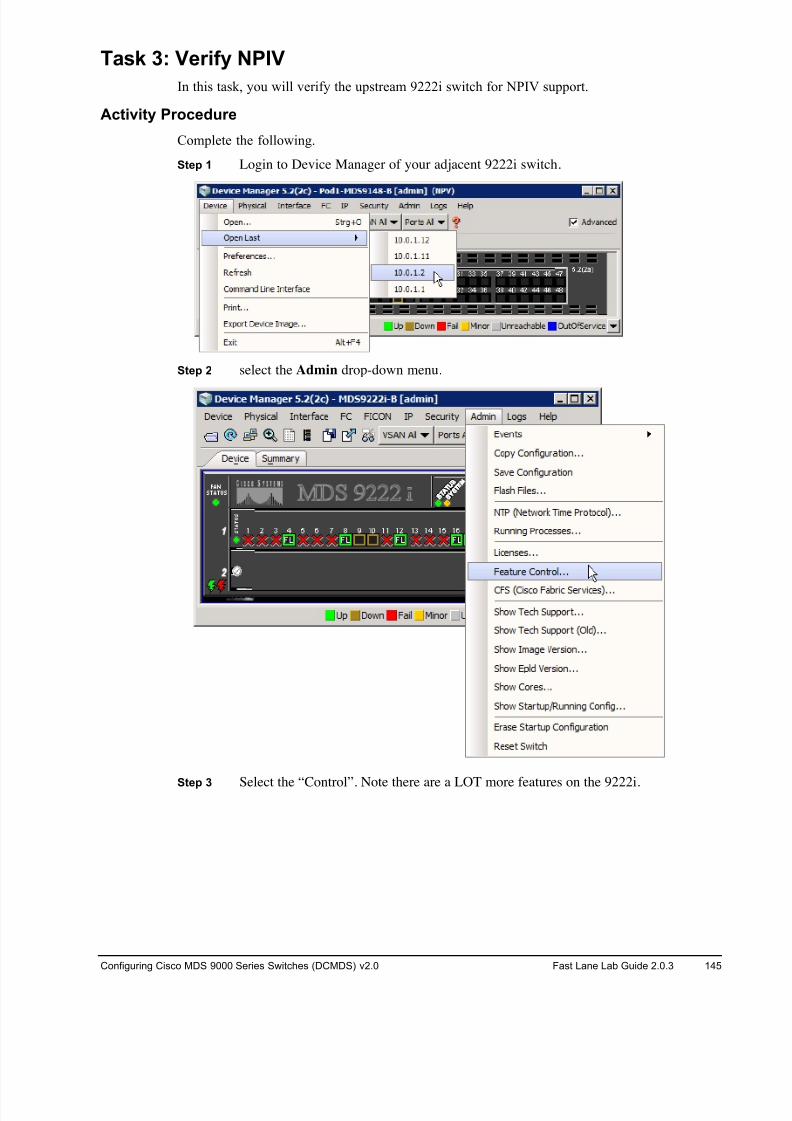
8/18/2019 FL_DCMDS_2.0.3_LG(1).pdf
http://slidepdf.com/reader/full/fldcmds203lg1pdf 145/482
Configuring Cisco MDS 9000 Series Switches (DCMDS) v2.0 Fast Lane Lab Guide 2.0.3 145
Task 3: Verify NPIV
In this task, you will verify the upstream 9222i switch for NPIV support.
Activity Procedure
Complete the following.
Step 1 Login to Device Manager of your adjacent 9222i switch.
Step 2 select the Admin drop-down menu.
Step 3 Select the “Control”. Note there are a LOT more features on the 9222i.
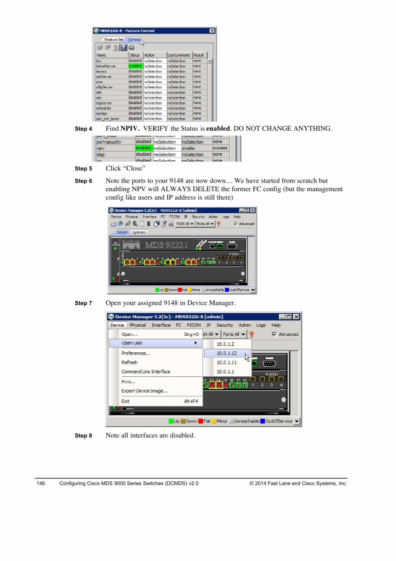
8/18/2019 FL_DCMDS_2.0.3_LG(1).pdf
http://slidepdf.com/reader/full/fldcmds203lg1pdf 146/482
146 Configuring Cisco MDS 9000 Series Switches (DCMDS) v2.0 © 2014 Fast Lane and Cisco Systems, Inc.
Step 4 Find NPIV. VERIFY the Status is enabled. DO NOT CHANGE ANYTHING.
Step 5 Click “Close”
Step 6 Note the ports to your 9148 are now down… We have started from scratch but
enabling NPV will ALWAYS DELETE the former FC config (but the management
config like users and IP address is still there)
Step 7 Open your assigned 9148 in Device Manager.
Step 8 Note all interfaces are disabled.
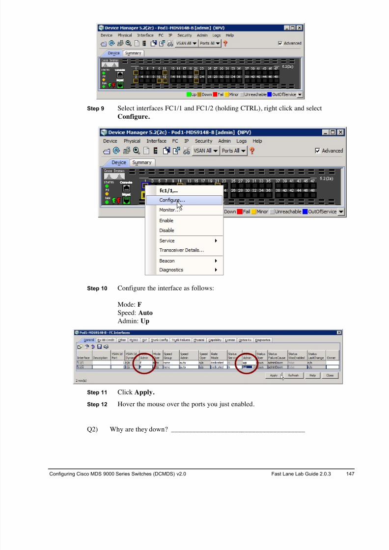
8/18/2019 FL_DCMDS_2.0.3_LG(1).pdf
http://slidepdf.com/reader/full/fldcmds203lg1pdf 147/482
Configuring Cisco MDS 9000 Series Switches (DCMDS) v2.0 Fast Lane Lab Guide 2.0.3 147
Step 9 Select interfaces FC1/1 and FC1/2 (holding CTRL), right click and select
Configure.
Step 10 Configure the interface as follows:
Mode: F
Speed: Auto
Admin: Up
Step 11 Click Apply.
Step 12 Hover the mouse over the ports you just enabled.
Q2) Why are they down? ______________________________________
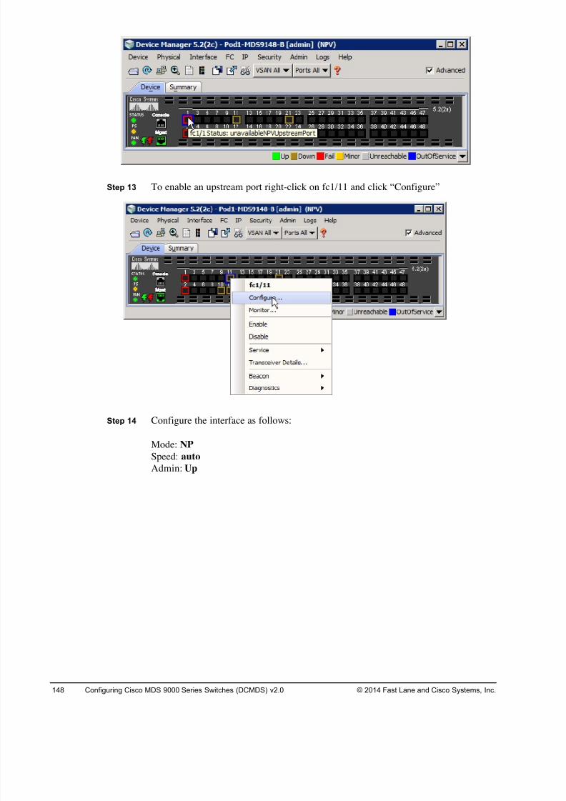
8/18/2019 FL_DCMDS_2.0.3_LG(1).pdf
http://slidepdf.com/reader/full/fldcmds203lg1pdf 148/482
148 Configuring Cisco MDS 9000 Series Switches (DCMDS) v2.0 © 2014 Fast Lane and Cisco Systems, Inc.
Step 13 To enable an upstream port right-click on fc1/11 and click “Configure”
Step 14 Configure the interface as follows:
Mode: NP
Speed: auto
Admin: Up
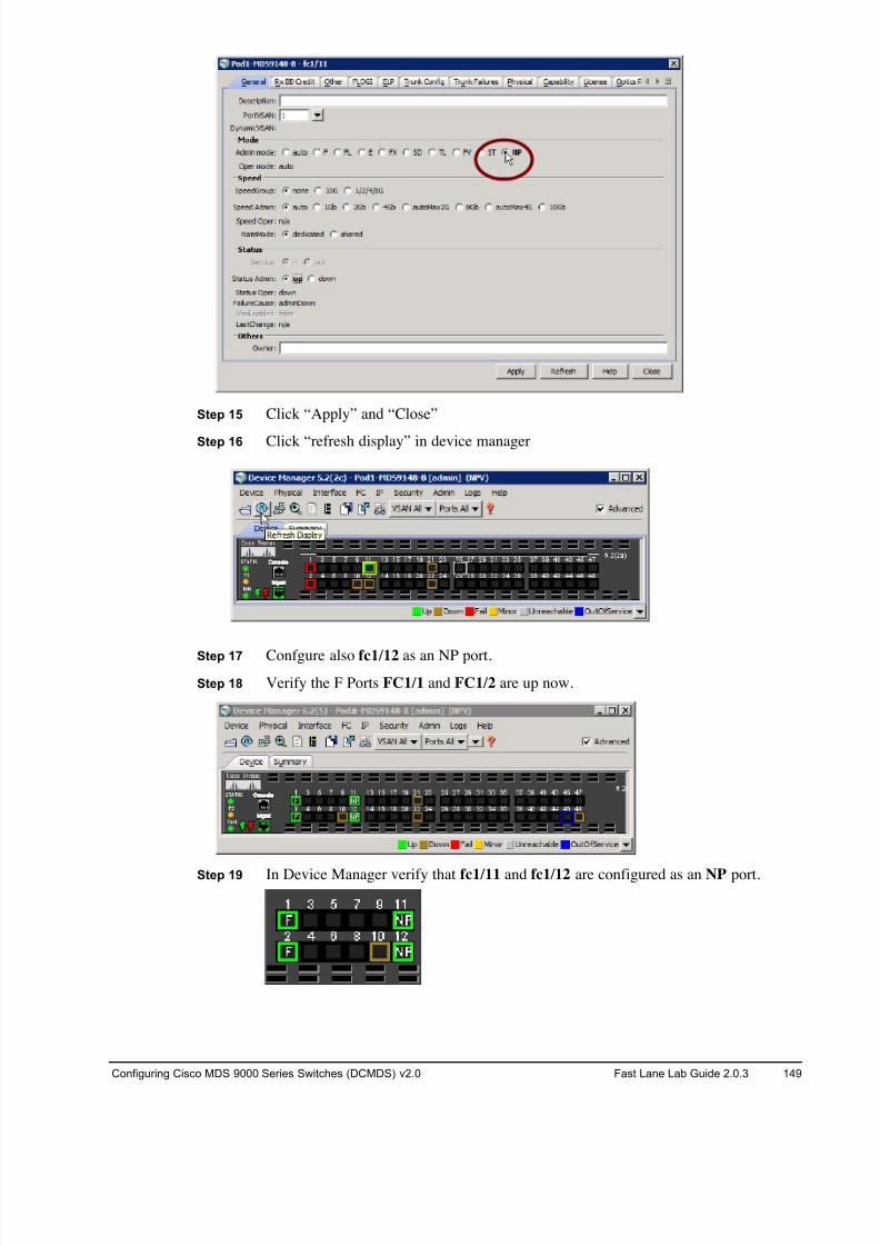
8/18/2019 FL_DCMDS_2.0.3_LG(1).pdf
http://slidepdf.com/reader/full/fldcmds203lg1pdf 149/482
Configuring Cisco MDS 9000 Series Switches (DCMDS) v2.0 Fast Lane Lab Guide 2.0.3 149
Step 15 Click “Apply” and “Close”
Step 16 Click “refresh display” in device manager
Step 17 Confgure also fc1/12 as an NP port.
Step 18 Verify the F Ports FC1/1 and FC1/2 are up now.
Step 19 In Device Manager verify that fc1/11 and fc1/12 are configured as an NP port.
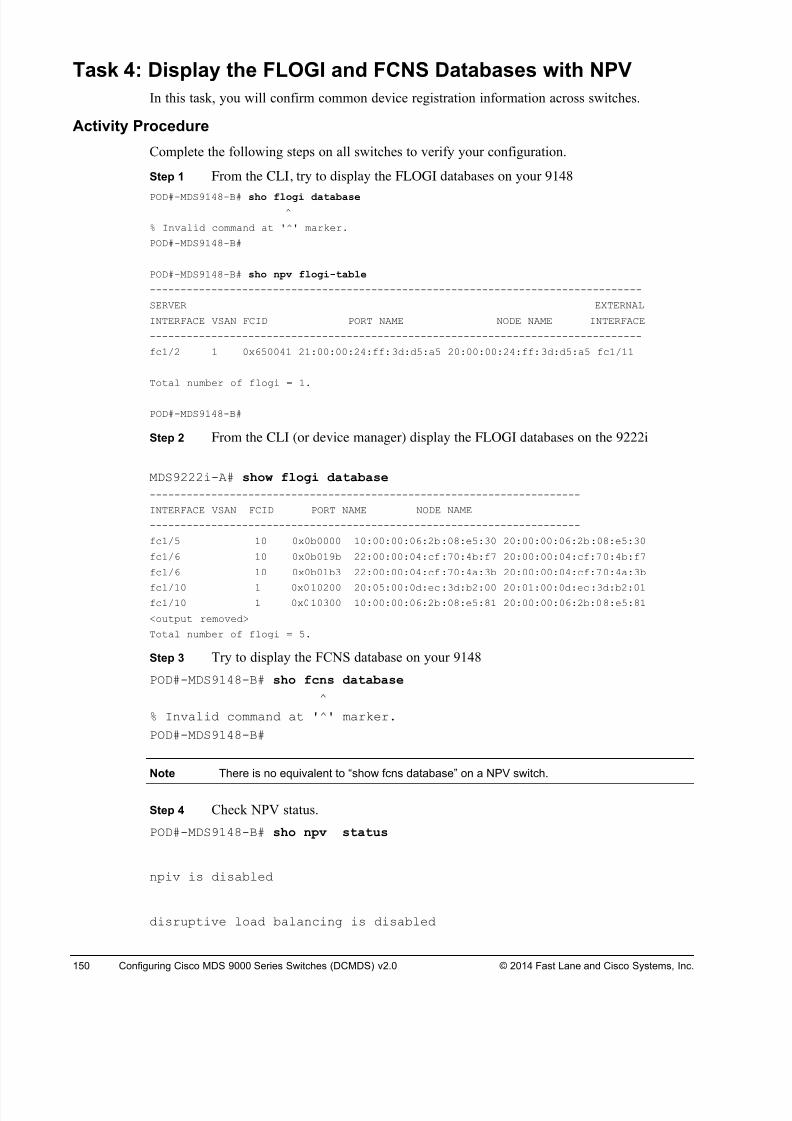
8/18/2019 FL_DCMDS_2.0.3_LG(1).pdf
http://slidepdf.com/reader/full/fldcmds203lg1pdf 150/482
150 Configuring Cisco MDS 9000 Series Switches (DCMDS) v2.0 © 2014 Fast Lane and Cisco Systems, Inc.
Task 4: Display the FLOGI and FCNS Databases with NPV
In this task, you will confirm common device registration information across switches.
Activity Procedure
Complete the following steps on all switches to verify your configuration.
Step 1 From the CLI, try to display the FLOGI databases on your 9148
POD#-MDS9148-B# sho flogi database^
% Invalid command at '^' marker.
POD#-MDS9148-B#
POD#-MDS9148-B# sho npv flogi-table
--------------------------------------------------------------------------------
SERVER EXTERNAL
INTERFACE VSAN FCID PORT NAME NODE NAME INTERFACE
--------------------------------------------------------------------------------
fc1/2 1 0x650041 21:00:00:24:ff:3d:d5:a5 20:00:00:24:ff:3d:d5:a5 fc1/11
Total number of flogi = 1.
POD#-MDS9148-B#
Step 2 From the CLI (or device manager) display the FLOGI databases on the 9222i
MDS9222i-A# show flogi database
----------------------------------------------------------------------
INTERFACE VSAN FCID PORT NAME NODE NAME
----------------------------------------------------------------------
fc1/5 10 0x0b0000 10:00:00:06:2b:08:e5:30 20:00:00:06:2b:08:e5:30
fc1/6 10 0x0b019b 22:00:00:04:cf:70:4b:f7 20:00:00:04:cf:70:4b:f7
fc1/6 10 0x0b01b3 22:00:00:04:cf:70:4a:3b 20:00:00:04:cf:70:4a:3b
fc1/10 1 0x010200 20:05:00:0d:ec:3d:b2:00 20:01:00:0d:ec:3d:b2:01fc1/10 1 0x010300 10:00:00:06:2b:08:e5:81 20:00:00:06:2b:08:e5:81
<output removed>
Total number of flogi = 5.
Step 3 Try to display the FCNS database on your 9148
POD#-MDS9148-B# sho fcns database
^
% Invalid command at '^' marker.
POD#-MDS9148-B#
Note There is no equivalent to “show fcns database” on a NPV switch.
Step 4 Check NPV status.
POD#-MDS9148-B# sho npv status
npiv is disabled
disruptive load balancing is disabled
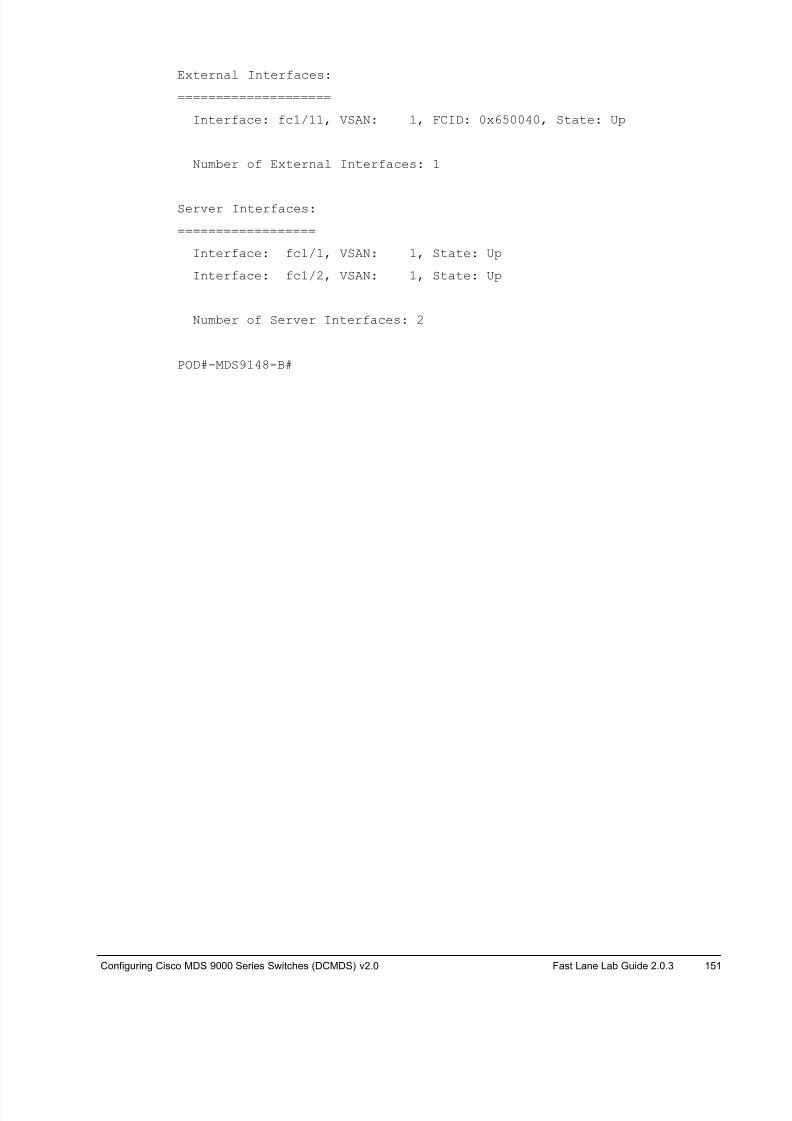
8/18/2019 FL_DCMDS_2.0.3_LG(1).pdf
http://slidepdf.com/reader/full/fldcmds203lg1pdf 151/482
Configuring Cisco MDS 9000 Series Switches (DCMDS) v2.0 Fast Lane Lab Guide 2.0.3 151
External Interfaces:
====================
Interface: fc1/11, VSAN: 1, FCID: 0x650040, State: Up
Number of External Interfaces: 1
Server Interfaces:
==================
Interface: fc1/1, VSAN: 1, State: Up
Interface: fc1/2, VSAN: 1, State: Up
Number of Server Interfaces: 2
POD#-MDS9148-B#
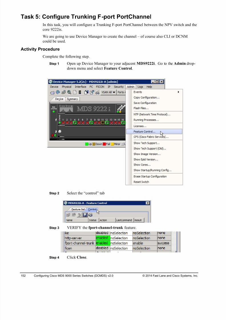
8/18/2019 FL_DCMDS_2.0.3_LG(1).pdf
http://slidepdf.com/reader/full/fldcmds203lg1pdf 152/482
152 Configuring Cisco MDS 9000 Series Switches (DCMDS) v2.0 © 2014 Fast Lane and Cisco Systems, Inc.
Task 5: Configure Trunking F-port PortChannel
In this task, you will configure a Trunking F-port PortChannel between the NPV switch and the
core 9222is.
We are going to use Device Manager to create the channel – of course also CLI or DCNM
could be used.
Activity Procedure
Complete the following step.
Step 1 Open up Device Manager to your adjacent MDS9222i. Go to the Admin drop-
down menu and select Feature Control.
Step 2 Select the “control” tab
Step 3 VERIFY the fport-channel-trunk feature.
Step 4 Click Close.
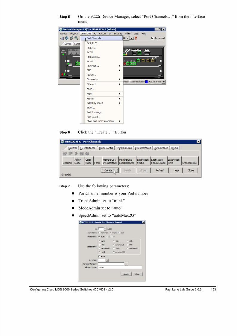
8/18/2019 FL_DCMDS_2.0.3_LG(1).pdf
http://slidepdf.com/reader/full/fldcmds203lg1pdf 153/482
Configuring Cisco MDS 9000 Series Switches (DCMDS) v2.0 Fast Lane Lab Guide 2.0.3 153
Step 5 On the 9222i Device Manager, select “Port Channels…” from the interface
menu.
Step 6 Click the “Create…” Button
Step 7 Use the following parameters:
! PortChannel number is your Pod number
! TrunkAdmin set to “trunk”
! ModeAdmin set to “auto”
! SpeedAdmin set to “autoMax2G”
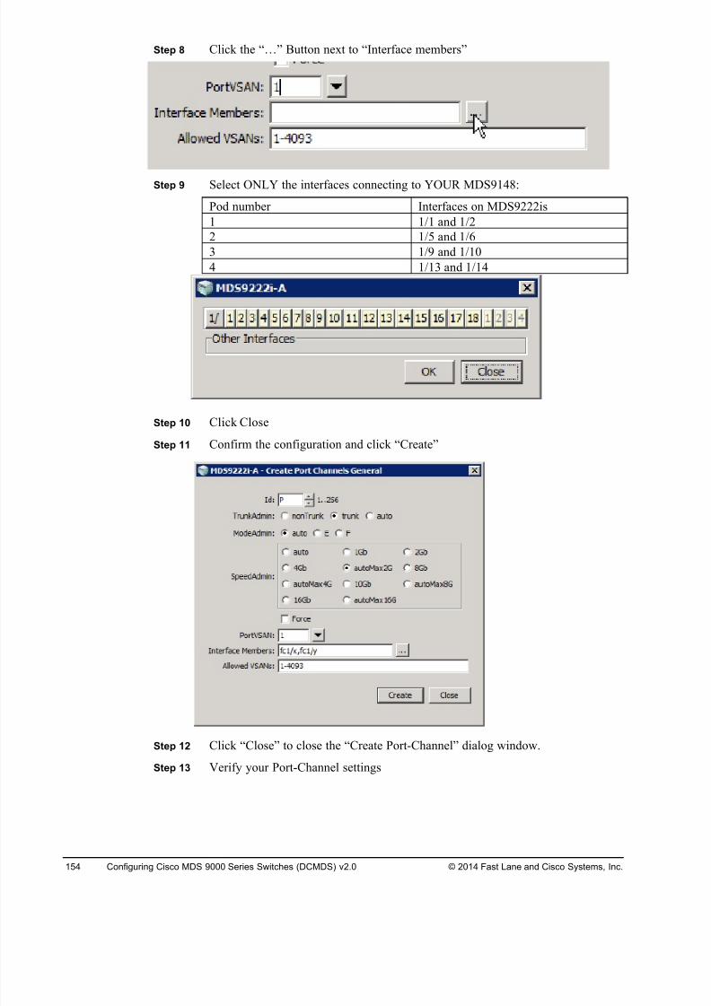
8/18/2019 FL_DCMDS_2.0.3_LG(1).pdf
http://slidepdf.com/reader/full/fldcmds203lg1pdf 154/482
154 Configuring Cisco MDS 9000 Series Switches (DCMDS) v2.0 © 2014 Fast Lane and Cisco Systems, Inc.
Step 8 Click the “…” Button next to “Interface members”
Step 9 Select ONLY the interfaces connecting to YOUR MDS9148:
Pod number Interfaces on MDS9222is
1 1/1 and 1/2
2 1/5 and 1/6
3 1/9 and 1/10
4 1/13 and 1/14
Step 10 Click Close
Step 11 Confirm the configuration and click “Create”
Step 12 Click “Close” to close the “Create Port-Channel” dialog window.
Step 13 Verify your Port-Channel settings
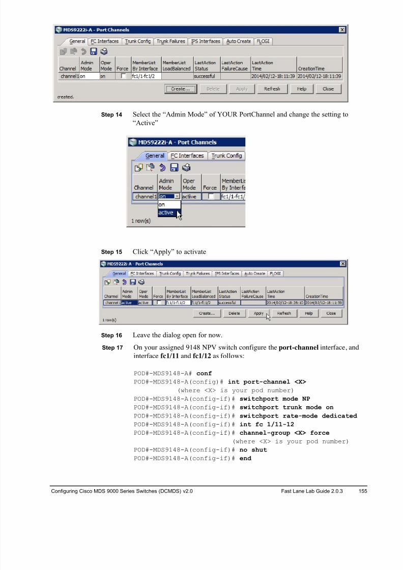
8/18/2019 FL_DCMDS_2.0.3_LG(1).pdf
http://slidepdf.com/reader/full/fldcmds203lg1pdf 155/482
Configuring Cisco MDS 9000 Series Switches (DCMDS) v2.0 Fast Lane Lab Guide 2.0.3 155
Step 14 Select the “Admin Mode” of YOUR PortChannel and change the setting to
“Active”
Step 15 Click “Apply” to activate
Step 16 Leave the dialog open for now.
Step 17 On your assigned 9148 NPV switch configure the port-channel interface, and
interface fc1/11 and fc1/12 as follows:
POD#-MDS9148-A# conf
POD#-MDS9148-A(config)# int port-channel <X>
(where <X> is your pod number)
POD#-MDS9148-A(config-if)# switchport mode NPPOD#-MDS9148-A(config-if)# switchport trunk mode on
POD#-MDS9148-A(config-if)# switchport rate-mode dedicated
POD#-MDS9148-A(config-if)# int fc 1/11-12
POD#-MDS9148-A(config-if)# channel-group <X> force
(where <X> is your pod number)
POD#-MDS9148-A(config-if)# no shut
POD#-MDS9148-A(config-if)# end
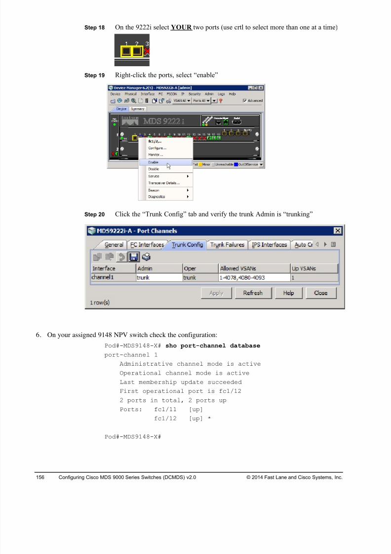
8/18/2019 FL_DCMDS_2.0.3_LG(1).pdf
http://slidepdf.com/reader/full/fldcmds203lg1pdf 156/482
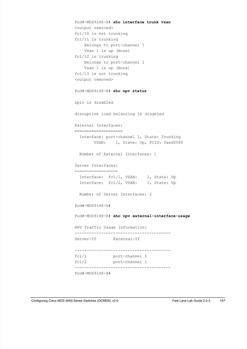
8/18/2019 FL_DCMDS_2.0.3_LG(1).pdf
http://slidepdf.com/reader/full/fldcmds203lg1pdf 157/482
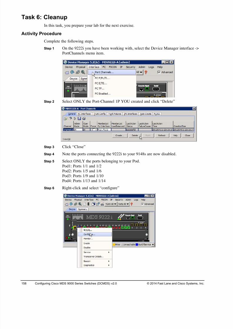
8/18/2019 FL_DCMDS_2.0.3_LG(1).pdf
http://slidepdf.com/reader/full/fldcmds203lg1pdf 158/482
158 Configuring Cisco MDS 9000 Series Switches (DCMDS) v2.0 © 2014 Fast Lane and Cisco Systems, Inc.
Task 6: Cleanup
In this task, you prepare your lab for the next exercise.
Activity Procedure
Complete the following steps.
Step 1 On the 9222i you have been working with, select the Device Manager interface ->
PortChannels menu item.
Step 2 Select ONLY the Port-Channel 1P YOU created and click “Delete”
Step 3 Click “Close”
Step 4 Note the ports connecting the 9222i to your 9148s are now disabled.
Step 5 Select ONLY the ports belonging to your Pod.
Pod1: Ports 1/1 and 1/2
Pod2: Ports 1/5 and 1/6Pod3: Ports 1/9 and 1/10
Pod4: Ports 1/13 and 1/14
Step 6 Right-click and select “configure”
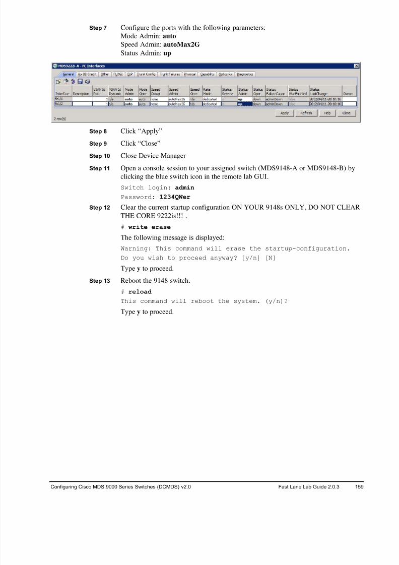
8/18/2019 FL_DCMDS_2.0.3_LG(1).pdf
http://slidepdf.com/reader/full/fldcmds203lg1pdf 159/482
Configuring Cisco MDS 9000 Series Switches (DCMDS) v2.0 Fast Lane Lab Guide 2.0.3 159
Step 7 Configure the ports with the following parameters:
Mode Admin: auto
Speed Admin: autoMax2G
Status Admin: up
Step 8 Click “Apply”
Step 9 Click “Close”
Step 10 Close Device Manager
Step 11 Open a console session to your assigned switch (MDS9148-A or MDS9148-B) by
clicking the blue switch icon in the remote lab GUI.
Switch login: admin
Password: 1234QWer Step 12 Clear the current startup configuration ON YOUR 9148s ONLY, DO NOT CLEAR
THE CORE 9222is!!! .
# write erase
The following message is displayed:
Warning: This command will erase the startup-configuration.
Do you wish to proceed anyway? [y/n] [N]
Type y to proceed.
Step 13 Reboot the 9148 switch.
# reload
This command will reboot the system. (y/n)?
Type y to proceed.
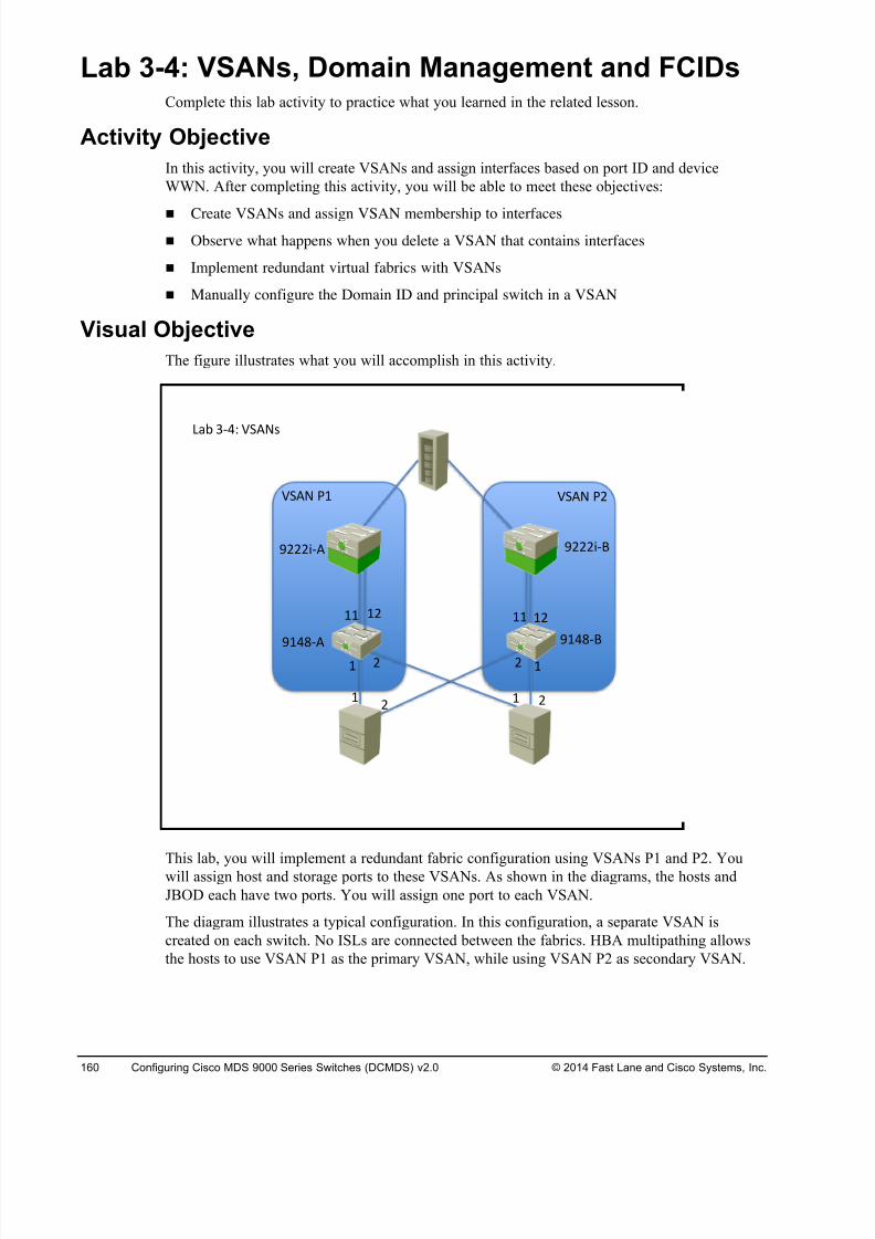
8/18/2019 FL_DCMDS_2.0.3_LG(1).pdf
http://slidepdf.com/reader/full/fldcmds203lg1pdf 160/482
160 Configuring Cisco MDS 9000 Series Switches (DCMDS) v2.0 © 2014 Fast Lane and Cisco Systems, Inc.
Lab 3-4: VSANs, Domain Management and FCIDs Complete this lab activity to practice what you learned in the related lesson.
Activity Objective
In this activity, you will create VSANs and assign interfaces based on port ID and device
WWN. After completing this activity, you will be able to meet these objectives:
! Create VSANs and assign VSAN membership to interfaces
! Observe what happens when you delete a VSAN that contains interfaces
! Implement redundant virtual fabrics with VSANs
! Manually configure the Domain ID and principal switch in a VSAN
Visual Objective
The figure illustrates what you will accomplish in this activity.
This lab, you will implement a redundant fabric configuration using VSANs P1 and P2. You
will assign host and storage ports to these VSANs. As shown in the diagrams, the hosts and
JBOD each have two ports. You will assign one port to each VSAN.
The diagram illustrates a typical configuration. In this configuration, a separate VSAN is
created on each switch. No ISLs are connected between the fabrics. HBA multipathing allows
the hosts to use VSAN P1 as the primary VSAN, while using VSAN P2 as secondary VSAN.
! !# #
!# !! !#!!
!# #!
$!%&'( $!%&')
$###*'( $###*')
+,- .'%/ 01(23
01(2 4! 01(2 4#
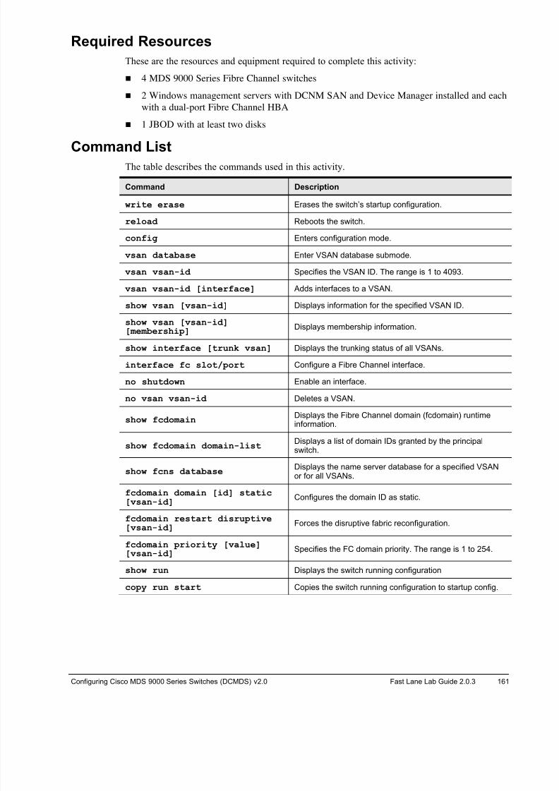
8/18/2019 FL_DCMDS_2.0.3_LG(1).pdf
http://slidepdf.com/reader/full/fldcmds203lg1pdf 161/482
Configuring Cisco MDS 9000 Series Switches (DCMDS) v2.0 Fast Lane Lab Guide 2.0.3 161
Required Resources
These are the resources and equipment required to complete this activity:
! 4 MDS 9000 Series Fibre Channel switches
! 2 Windows management servers with DCNM SAN and Device Manager installed and each
with a dual-port Fibre Channel HBA
! 1 JBOD with at least two disks
Command List
The table describes the commands used in this activity.
Command Description
write erase Erases the switch’s startup configuration.
reload Reboots the switch.
config Enters configuration mode.
vsan database Enter VSAN database submode.
vsan vsan-id Specifies the VSAN ID. The range is 1 to 4093.
vsan vsan-id [interface] Adds interfaces to a VSAN.
show vsan [vsan-id] Displays information for the specified VSAN ID.
show vsan [vsan-id][membership]
Displays membership information.
show interface [trunk vsan] Displays the trunking status of all VSANs.
interface fc slot/port Configure a Fibre Channel interface.
no shutdown Enable an interface.
no vsan vsan-id Deletes a VSAN.
show fcdomain Displays the Fibre Channel domain (fcdomain) runtimeinformation.
show fcdomain domain-listDisplays a list of domain IDs granted by the principalswitch.
show fcns databaseDisplays the name server database for a specified VSANor for all VSANs.
fcdomain domain [id] static[vsan-id]
Configures the domain ID as static.
fcdomain restart disruptive[vsan-id]
Forces the disruptive fabric reconfiguration.
fcdomain priority [value]
[vsan-id]Specifies the FC domain priority. The range is 1 to 254.
show run Displays the switch running configuration
copy run start Copies the switch running configuration to startup config.
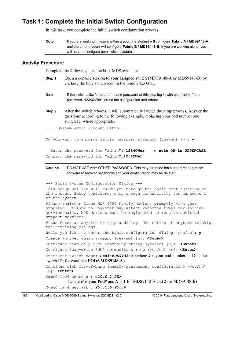
8/18/2019 FL_DCMDS_2.0.3_LG(1).pdf
http://slidepdf.com/reader/full/fldcmds203lg1pdf 162/482
162 Configuring Cisco MDS 9000 Series Switches (DCMDS) v2.0 © 2014 Fast Lane and Cisco Systems, Inc.
Task 1: Complete the Initial Switch Configuration
In this task, you complete the initial switch configuration process.
Note If you are working in teams within a pod, one student will configure Fabric A / MDS9148-A
and the other student will configure Fabric B / MDS9148-B. If you are working alone, you
will need to configure both switches/fabrics!
Activity Procedure
Complete the following steps on both MDS switches:
Step 1 Open a console session to your assigned switch (MDS9148-A or MDS9148-B) by
clicking the blue switch icon in the remote lab GUI.
Note If the switch asks for username and password at this step log in with user “admin” and
password “1234QWer”, erase the configuration and reboot.
Step 2 After the switch reboots, it will automatically launch the setup process. Answer the
questions according to the following example, replacing your pod number and
switch ID where appropriate.
---- System Admin Account Setup ----
Do you want to enforce secure password standard (yes/no) [y]: y
Enter the password for "admin": 1234QWer < note QW is UPPERCASE
Confirm the password for "admin":1234QWer
Caution DO NOT USE ANY OTHER PASSWORD. This may force the lab support management
software to recover passwords and your configuration may be deleted.
--- Basic System Configuration Dialog ---
This setup utility will guide you through the basic configuration ofthe system. Setup configures only enough connectivity for managementof the system.
Please register Cisco MDS 9000 Family devices promptly with yoursupplier. Failure to register may affect response times for initialservice calls. MDS devices must be registered to receive entitledsupport services.
Press Enter at anytime to skip a dialog. Use ctrl-c at anytime to skipthe remaining dialogs.
Would you like to enter the basic configuration dialog (yes/no): y
Create another login account (yes/no) [n]: <Enter>
Configure read-only SNMP community string (yes/no) [n]: <Enter>
Configure read-write SNMP community string (yes/no) [n]: <Enter>
Enter the switch name: Pod#-MDS9148-Y (where # is your pod number and Y is the
switch ID; for example: POD#-MDS9148-A)
Continue with Out-of-band (mgmt0) management configuration? (yes/no)[y]: <Enter>
Mgmt0 IPv4 address : <10.0.1.PN >
(where P is your Pod# and N is 1 for MDS9148-A and 2 for MDS9148-B)
Mgmt0 IPv4 netmask : 255.255.255.0

8/18/2019 FL_DCMDS_2.0.3_LG(1).pdf
http://slidepdf.com/reader/full/fldcmds203lg1pdf 163/482
Configuring Cisco MDS 9000 Series Switches (DCMDS) v2.0 Fast Lane Lab Guide 2.0.3 163
Configure the default gateway? (yes/no) [y]: <No>
Configure advanced IP options? (yes/no) [n]: <Enter>
Enable the ssh service? (yes/no) [y]: <No>
Enable the telnet service? (yes/no) [n]: <Yes>
Configure congestion/no_credit drop for fc interfaces? (yes/no)[y]: <Enter>
Enter the type of drop to configure congestion/no_credit drop?
(con/no) [c]: <Enter>Enter milliseconds in multiple of 10 for congestion-drop in range [100- 500], or [d/default] for default: <d>
Enter mode for congestion/no_credit drop[E/F]: <Enter>
Enable the http-server? (yes/no) [y]: <Enter>
Configure clock? (yes/no) [n]: <Enter>
Configure timezone? (yes/no) [n]: <Enter>
Configure summertime? (yes/no) [n]: <Enter>
Configure the ntp server? (yes/no) [n]: <Enter>
Configure default switchport interface state (shut/noshut) [shut]: <Enter>
Configure default switchport trunk mode (on/off/auto) [on]: <Enter> Configure default switchport port mode F (yes/no) [n]: <Enter>
Configure default zone policy (permit/deny) [deny]: <Enter>
Enable full zoneset distribution (yes/no) [n]: <Enter>
Configure default zone mode (basic/enhanced) [basic]: <Enter>
Step 3 A summary of the configuration will be displayed:
The following configuration will be applied:
password strength-check
switchname POD#-MDS9148-A
interface mgmt0
ip address 10.0.1.PN 255.255.255.0
no shutdown
no feature ssh
feature telnet
feature http-server
system default switchport shutdown
system default switchport trunk mode on
no system default zone default-zone permit
no system default zone distribute full
no system default zone mode enhanced
Step 4 Press Enter twice to save the configuration.
Would you like to edit the configuration? (yes/no) [n]: <Enter>
Use this configuration and save it? (yes/no) [y]: <Enter>
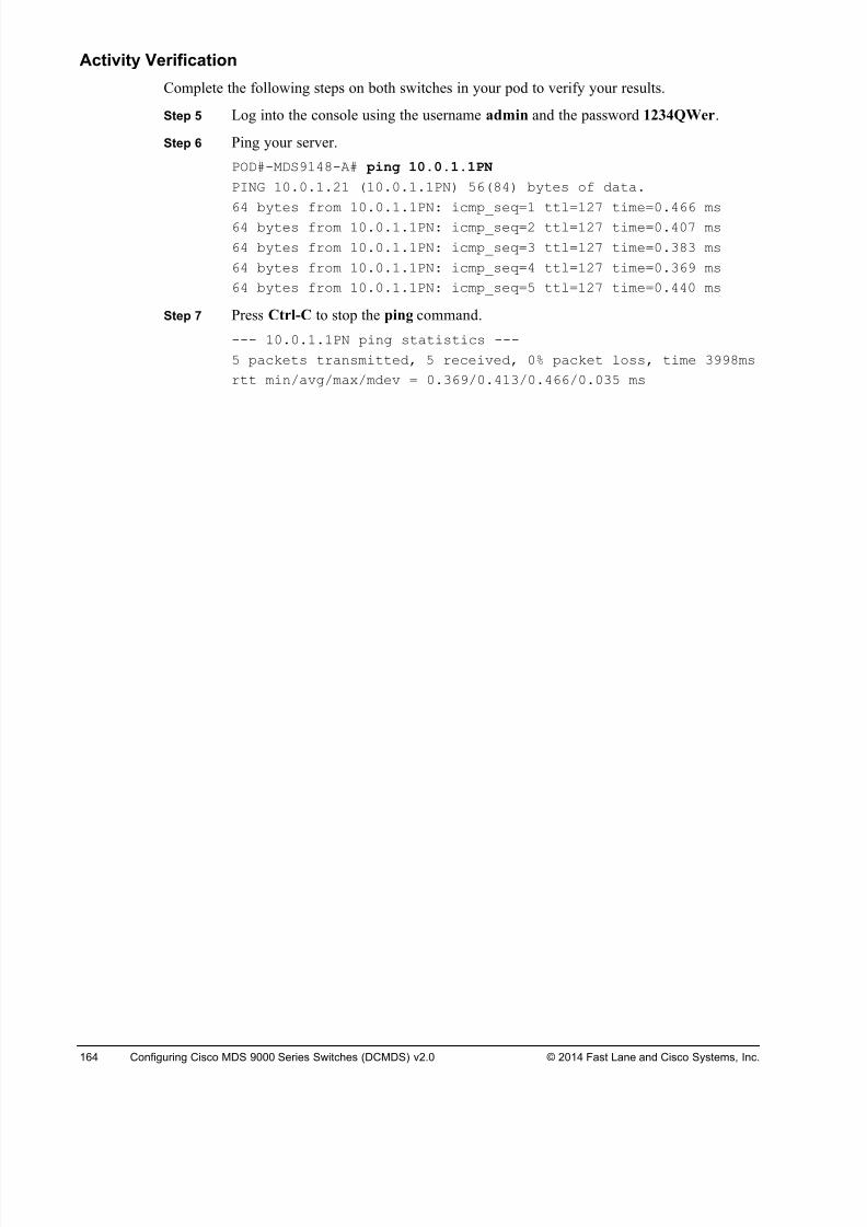
8/18/2019 FL_DCMDS_2.0.3_LG(1).pdf
http://slidepdf.com/reader/full/fldcmds203lg1pdf 164/482
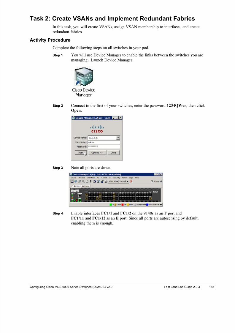
8/18/2019 FL_DCMDS_2.0.3_LG(1).pdf
http://slidepdf.com/reader/full/fldcmds203lg1pdf 165/482
Configuring Cisco MDS 9000 Series Switches (DCMDS) v2.0 Fast Lane Lab Guide 2.0.3 165
Task 2: Create VSANs and Implement Redundant Fabrics
In this task, you will create VSANs, assign VSAN membership to interfaces, and create
redundant fabrics.
Activity Procedure
Complete the following steps on all switches in your pod.
Step 1 You will use Device Manager to enable the links between the switches you are
managing. Launch Device Manager.
Step 2 Connect to the first of your switches, enter the password 1234QWer, then click
Open.
Step 3 Note all ports are down.
Step 4 Enable interfaces FC1/1 and FC1/2 on the 9148s as an F port and
FC1/11 and FC1/12 as an E port. Since all ports are autosensing by default,
enabling them is enough.
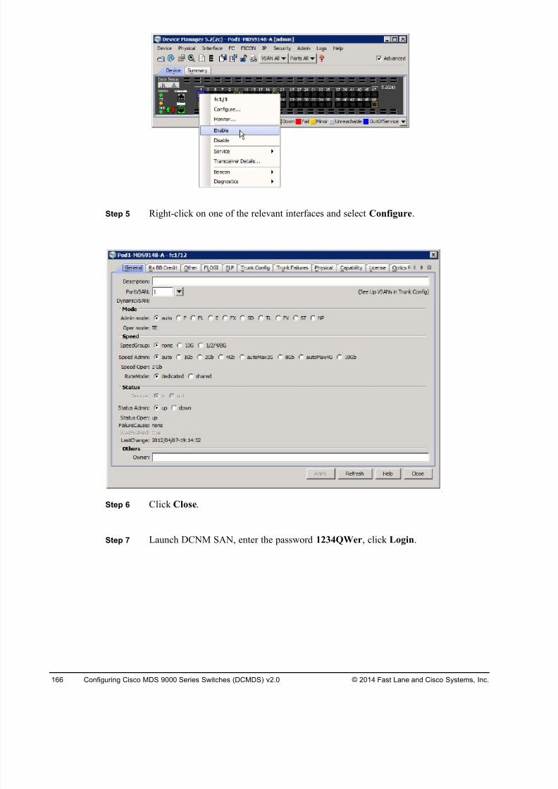
8/18/2019 FL_DCMDS_2.0.3_LG(1).pdf
http://slidepdf.com/reader/full/fldcmds203lg1pdf 166/482
166 Configuring Cisco MDS 9000 Series Switches (DCMDS) v2.0 © 2014 Fast Lane and Cisco Systems, Inc.
Step 5 Right-click on one of the relevant interfaces and select Configure.
Step 6 Click Close.
Step 7 Launch DCNM SAN, enter the password 1234QWer, click Login.
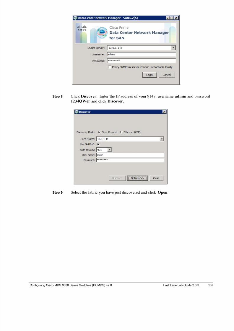
8/18/2019 FL_DCMDS_2.0.3_LG(1).pdf
http://slidepdf.com/reader/full/fldcmds203lg1pdf 167/482
Configuring Cisco MDS 9000 Series Switches (DCMDS) v2.0 Fast Lane Lab Guide 2.0.3 167
Step 8 Click Discover. Enter the IP address of your 9148, username admin and password
1234QWer and click Discover.
Step 9 Select the fabric you have just discovered and click Open.
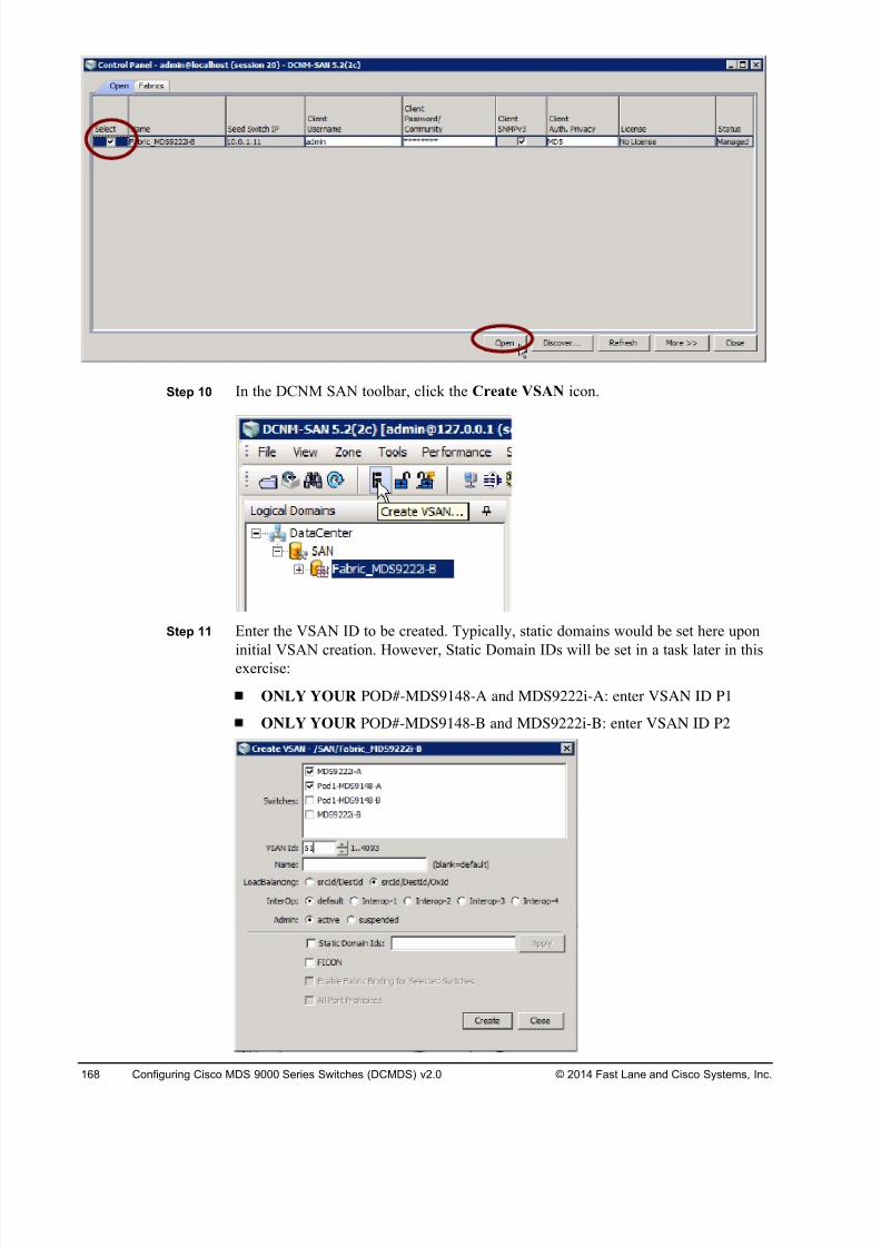
8/18/2019 FL_DCMDS_2.0.3_LG(1).pdf
http://slidepdf.com/reader/full/fldcmds203lg1pdf 168/482
168 Configuring Cisco MDS 9000 Series Switches (DCMDS) v2.0 © 2014 Fast Lane and Cisco Systems, Inc.
Step 10 In the DCNM SAN toolbar, click the Create VSAN icon.
Step 11 Enter the VSAN ID to be created. Typically, static domains would be set here upon
initial VSAN creation. However, Static Domain IDs will be set in a task later in thisexercise:
ONLY YOUR POD#-MDS9148-A and MDS9222i-A: enter VSAN ID P1
ONLY YOUR POD#-MDS9148-B and MDS9222i-B: enter VSAN ID P2
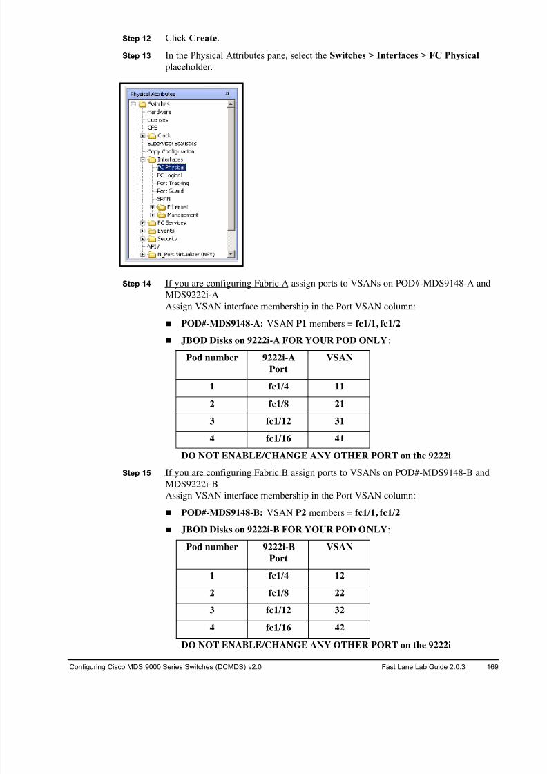
8/18/2019 FL_DCMDS_2.0.3_LG(1).pdf
http://slidepdf.com/reader/full/fldcmds203lg1pdf 169/482
Configuring Cisco MDS 9000 Series Switches (DCMDS) v2.0 Fast Lane Lab Guide 2.0.3 169
Step 12 Click Create.
Step 13 In the Physical Attributes pane, select the Switches > Interfaces > FC Physical
placeholder.
Step 14 If you are configuring Fabric A assign ports to VSANs on POD#-MDS9148-A and
MDS9222i-A
Assign VSAN interface membership in the Port VSAN column:
! POD#-MDS9148-A: VSAN P1 members = fc1/1, fc1/2
! JBOD Disks on 9222i-A FOR YOUR POD ONLY:
Pod number 9222i-A
Port
VSAN
1 fc1/4 11
2 fc1/8 213 fc1/12 31
4 fc1/16 41
DO NOT ENABLE/CHANGE ANY OTHER PORT on the 9222i
Step 15 If you are configuring Fabric B assign ports to VSANs on POD#-MDS9148-B and
MDS9222i-B
Assign VSAN interface membership in the Port VSAN column:
! POD#-MDS9148-B: VSAN P2 members = fc1/1, fc1/2
! JBOD Disks on 9222i-B FOR YOUR POD ONLY:
Pod number 9222i-B
Port
VSAN
1 fc1/4 12
2 fc1/8 22
3 fc1/12 32
4 fc1/16 42
DO NOT ENABLE/CHANGE ANY OTHER PORT on the 9222i
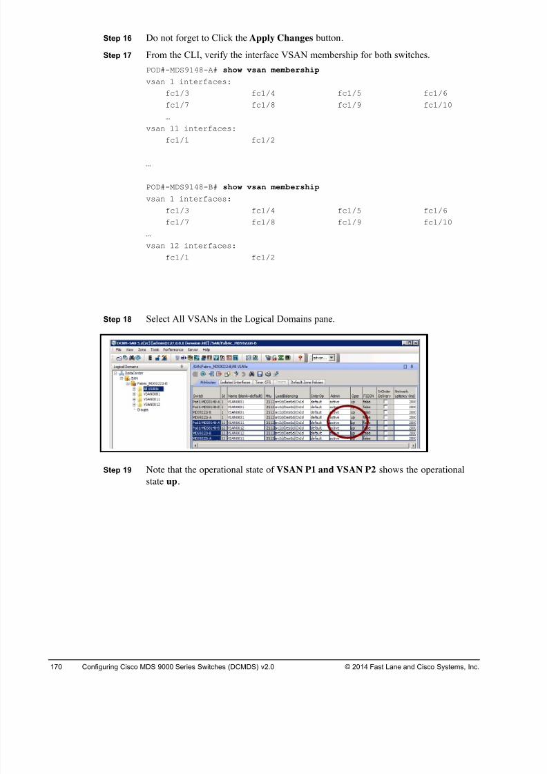
8/18/2019 FL_DCMDS_2.0.3_LG(1).pdf
http://slidepdf.com/reader/full/fldcmds203lg1pdf 170/482
170 Configuring Cisco MDS 9000 Series Switches (DCMDS) v2.0 © 2014 Fast Lane and Cisco Systems, Inc.
Step 16 Do not forget to Click the Apply Changes button.
Step 17 From the CLI, verify the interface VSAN membership for both switches.
POD#-MDS9148-A# show vsan membership
vsan 1 interfaces:
fc1/3 fc1/4 fc1/5 fc1/6
fc1/7 fc1/8 fc1/9 fc1/10
…
vsan 11 interfaces:
fc1/1 fc1/2
…
POD#-MDS9148-B# show vsan membership
vsan 1 interfaces:
fc1/3 fc1/4 fc1/5 fc1/6
fc1/7 fc1/8 fc1/9 fc1/10
…
vsan 12 interfaces:
fc1/1 fc1/2
Step 18 Select All VSANs in the Logical Domains pane.
Step 19 Note that the operational state of VSAN P1 and VSAN P2 shows the operational
state up.
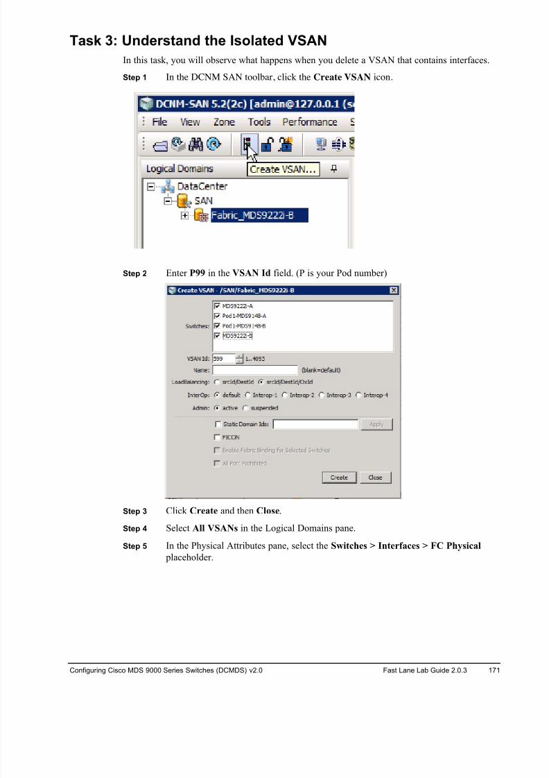
8/18/2019 FL_DCMDS_2.0.3_LG(1).pdf
http://slidepdf.com/reader/full/fldcmds203lg1pdf 171/482
Configuring Cisco MDS 9000 Series Switches (DCMDS) v2.0 Fast Lane Lab Guide 2.0.3 171
Task 3: Understand the Isolated VSAN
In this task, you will observe what happens when you delete a VSAN that contains interfaces.
Step 1 In the DCNM SAN toolbar, click the Create VSAN icon.
Step 2 Enter P99 in the VSAN Id field. (P is your Pod number)
Step 3 Click Create and then Close.
Step 4 Select All VSANs in the Logical Domains pane.
Step 5 In the Physical Attributes pane, select the Switches > Interfaces > FC Physical placeholder.
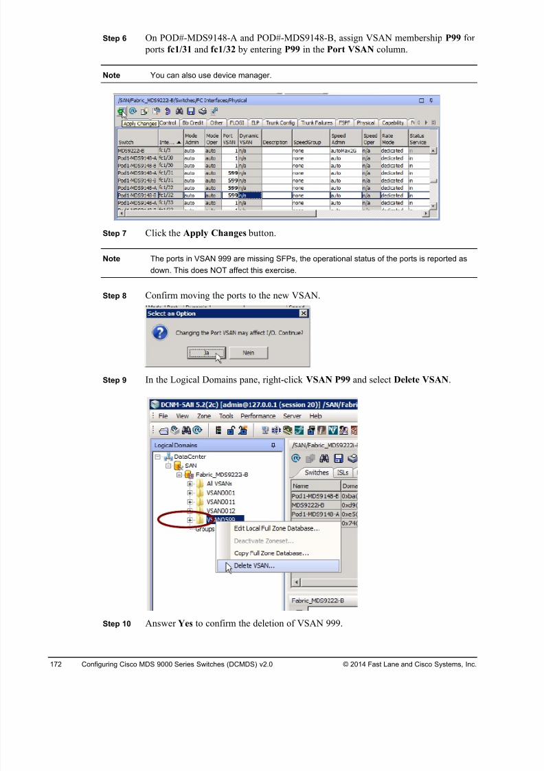
8/18/2019 FL_DCMDS_2.0.3_LG(1).pdf
http://slidepdf.com/reader/full/fldcmds203lg1pdf 172/482
172 Configuring Cisco MDS 9000 Series Switches (DCMDS) v2.0 © 2014 Fast Lane and Cisco Systems, Inc.
Step 6 On POD#-MDS9148-A and POD#-MDS9148-B, assign VSAN membership P99 for
ports fc1/31 and fc1/32 by entering P99 in the Port VSAN column.
Note You can also use device manager.
Step 7 Click the Apply Changes button.
Note The ports in VSAN 999 are missing SFPs, the operational status of the ports is reported as
down. This does NOT affect this exercise.
Step 8 Confirm moving the ports to the new VSAN.
Step 9 In the Logical Domains pane, right-click VSAN P99 and select Delete VSAN.
Step 10 Answer Yes to confirm the deletion of VSAN 999.
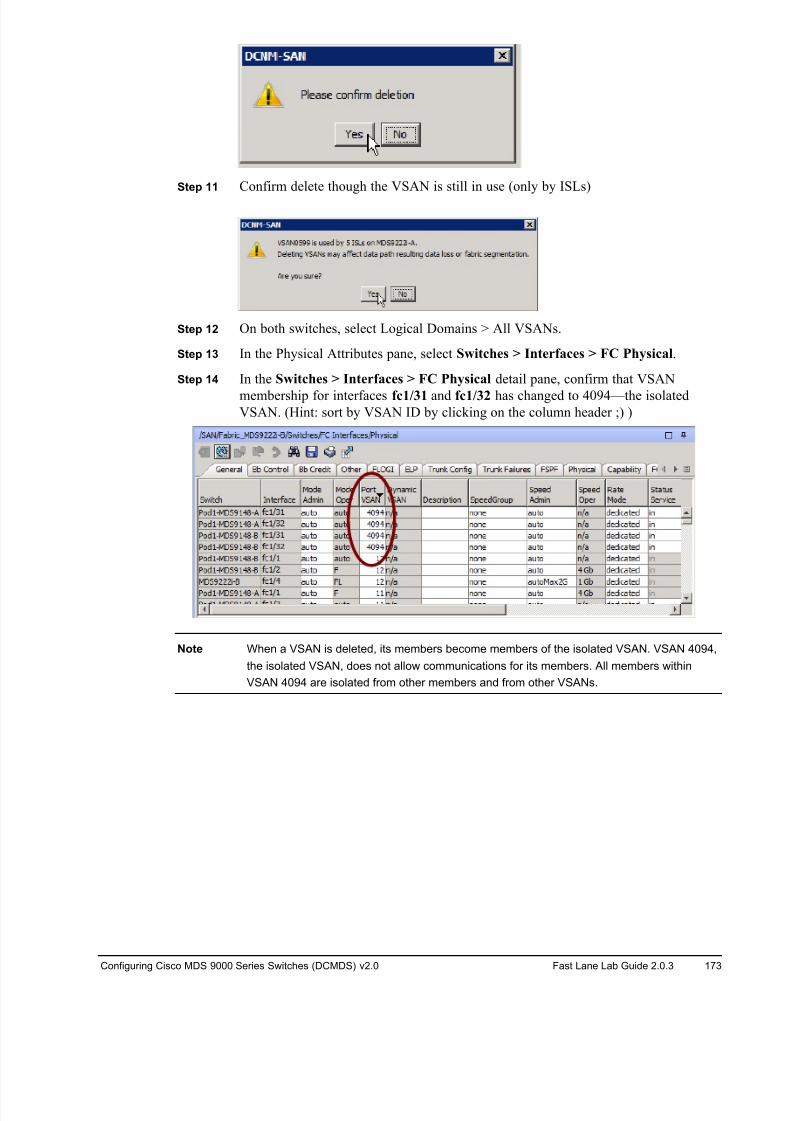
8/18/2019 FL_DCMDS_2.0.3_LG(1).pdf
http://slidepdf.com/reader/full/fldcmds203lg1pdf 173/482
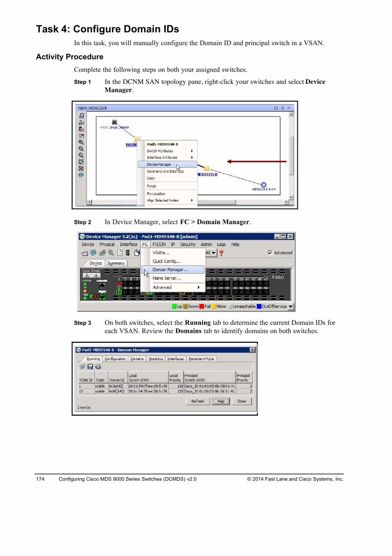
8/18/2019 FL_DCMDS_2.0.3_LG(1).pdf
http://slidepdf.com/reader/full/fldcmds203lg1pdf 174/482
174 Configuring Cisco MDS 9000 Series Switches (DCMDS) v2.0 © 2014 Fast Lane and Cisco Systems, Inc.
Task 4: Configure Domain IDs
In this task, you will manually configure the Domain ID and principal switch in a VSAN.
Activity Procedure
Complete the following steps on both your assigned switches.
Step 1 In the DCNM SAN topology pane, right-click your switches and select Device
Manager.
Step 2 In Device Manager, select FC > Domain Manager.
Step 3 On both switches, select the Running tab to determine the current Domain IDs for
each VSAN. Review the Domains tab to identify domains on both switches.
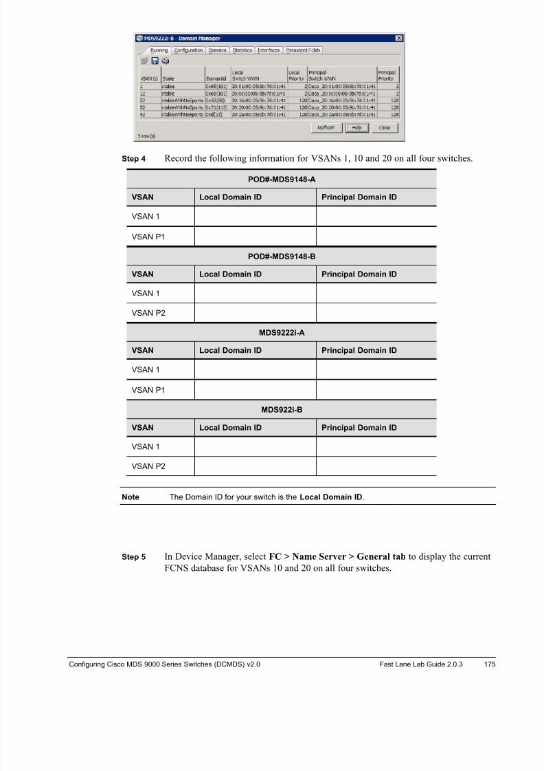
8/18/2019 FL_DCMDS_2.0.3_LG(1).pdf
http://slidepdf.com/reader/full/fldcmds203lg1pdf 175/482
Configuring Cisco MDS 9000 Series Switches (DCMDS) v2.0 Fast Lane Lab Guide 2.0.3 175
Step 4 Record the following information for VSANs 1, 10 and 20 on all four switches.
POD#-MDS9148-A
VSAN Local Domain ID Principal Domain ID
VSAN 1
VSAN P1
POD#-MDS9148-B
VSAN Local Domain ID Principal Domain ID
VSAN 1
VSAN P2
MDS9222i-A
VSAN Local Domain ID Principal Domain ID
VSAN 1
VSAN P1
MDS922i-B
VSAN Local Domain ID Principal Domain ID
VSAN 1
VSAN P2
Note The Domain ID for your switch is the Local Domain ID.
Step 5 In Device Manager, select FC > Name Server > General tab to display the current
FCNS database for VSANs 10 and 20 on all four switches.
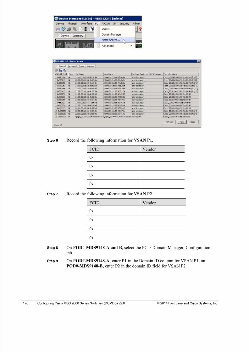
8/18/2019 FL_DCMDS_2.0.3_LG(1).pdf
http://slidepdf.com/reader/full/fldcmds203lg1pdf 176/482
176 Configuring Cisco MDS 9000 Series Switches (DCMDS) v2.0 © 2014 Fast Lane and Cisco Systems, Inc.
Step 6 Record the following information for VSAN P1.
FCID Vendor
0x
0x
0x
0x
Step 7 Record the following information for VSAN P2.
FCID Vendor
0x
0x
0x
0x
Step 8 On POD#-MDS9148-A and B, select the FC > Domain Manager, Configurationtab.
Step 9 On POD#-MDS9148-A, enter P1 in the Domain ID column for VSAN P1, on
POD#-MDS9148-B, enter P2 in the domain ID field for VSAN P2
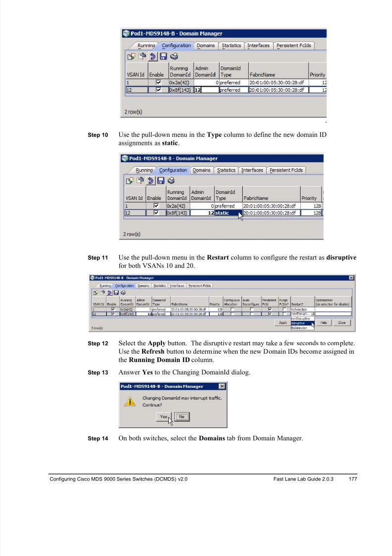
8/18/2019 FL_DCMDS_2.0.3_LG(1).pdf
http://slidepdf.com/reader/full/fldcmds203lg1pdf 177/482
Configuring Cisco MDS 9000 Series Switches (DCMDS) v2.0 Fast Lane Lab Guide 2.0.3 177
Step 10 Use the pull-down menu in the Type column to define the new domain ID
assignments as static.
Step 11 Use the pull-down menu in the Restart column to configure the restart as disruptive
for both VSANs 10 and 20.
Step 12 Select the Apply button. The disruptive restart may take a few seconds to complete.
Use the Refresh button to determine when the new Domain IDs become assigned in
the Running Domain ID column.
Step 13 Answer Yes to the Changing DomainId dialog.
Step 14 On both switches, select the Domains tab from Domain Manager.
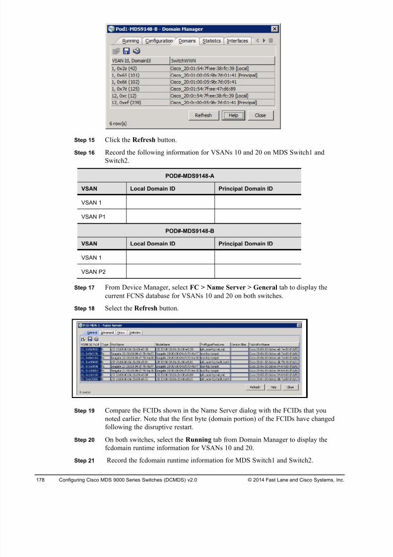
8/18/2019 FL_DCMDS_2.0.3_LG(1).pdf
http://slidepdf.com/reader/full/fldcmds203lg1pdf 178/482
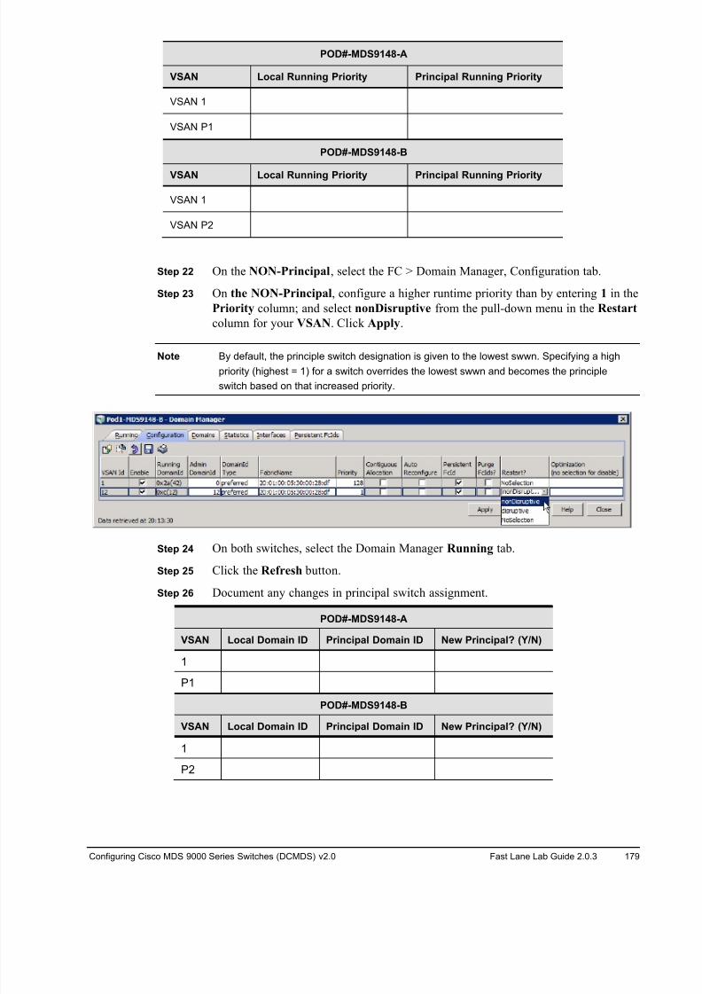
8/18/2019 FL_DCMDS_2.0.3_LG(1).pdf
http://slidepdf.com/reader/full/fldcmds203lg1pdf 179/482
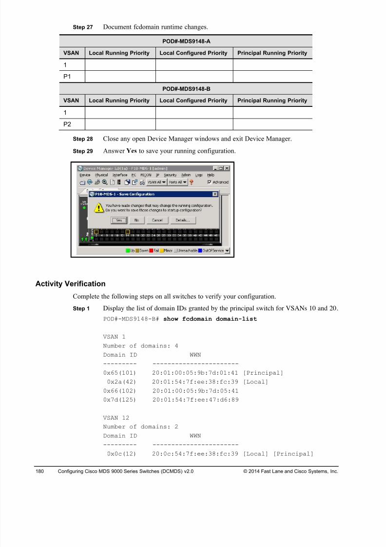
8/18/2019 FL_DCMDS_2.0.3_LG(1).pdf
http://slidepdf.com/reader/full/fldcmds203lg1pdf 180/482
180 Configuring Cisco MDS 9000 Series Switches (DCMDS) v2.0 © 2014 Fast Lane and Cisco Systems, Inc.
Step 27 Document fcdomain runtime changes.
POD#-MDS9148-A
VSAN Local Running Priority Local Configured Priority Principal Running Priority
1
P1
POD#-MDS9148-B
VSAN Local Running Priority Local Configured Priority Principal Running Priority
1
P2
Step 28 Close any open Device Manager windows and exit Device Manager.
Step 29 Answer Yes to save your running configuration.
Activity VerificationComplete the following steps on all switches to verify your configuration.
Step 1 Display the list of domain IDs granted by the principal switch for VSANs 10 and 20.
POD#-MDS9148-B# show fcdomain domain-list
VSAN 1
Number of domains: 4
Domain ID WWN
--------- -----------------------
0x65(101) 20:01:00:05:9b:7d:01:41 [Principal]
0x2a(42) 20:01:54:7f:ee:38:fc:39 [Local]0x66(102) 20:01:00:05:9b:7d:05:41
0x7d(125) 20:01:54:7f:ee:47:d6:89
VSAN 12
Number of domains: 2
Domain ID WWN
--------- -----------------------
0x0c(12) 20:0c:54:7f:ee:38:fc:39 [Local] [Principal]
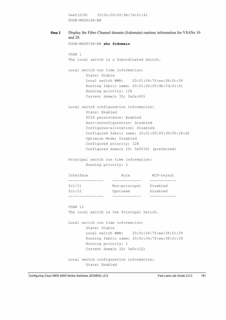
8/18/2019 FL_DCMDS_2.0.3_LG(1).pdf
http://slidepdf.com/reader/full/fldcmds203lg1pdf 181/482
Configuring Cisco MDS 9000 Series Switches (DCMDS) v2.0 Fast Lane Lab Guide 2.0.3 181
0xef(239) 20:0c:00:05:9b:7d:01:41
POD#-MDS9148-B#
Step 2 Display the Fibre Channel domain (fcdomain) runtime information for VSANs 10
and 20.
POD#-MDS9148-B# sho fcdomain
VSAN 1The local switch is a Subordinated Switch.
Local switch run time information:
State: Stable
Local switch WWN: 20:01:54:7f:ee:38:fc:39
Running fabric name: 20:01:00:05:9b:7d:01:41
Running priority: 128
Current domain ID: 0x2a(42)
Local switch configuration information:
State: EnabledFCID persistence: Enabled
Auto-reconfiguration: Disabled
Contiguous-allocation: Disabled
Configured fabric name: 20:01:00:05:30:00:28:df
Optimize Mode: Disabled
Configured priority: 128
Configured domain ID: 0x00(0) (preferred)
Principal switch run time information:
Running priority: 2
Interface Role RCF-reject
---------------- ------------- ------------
fc1/11 Non-principal Disabled
fc1/12 Upstream Disabled
---------------- ------------- ------------
VSAN 12
The local switch is the Principal Switch.
Local switch run time information:State: Stable
Local switch WWN: 20:0c:54:7f:ee:38:fc:39
Running fabric name: 20:0c:54:7f:ee:38:fc:39
Running priority: 1
Current domain ID: 0x0c(12)
Local switch configuration information:
State: Enabled
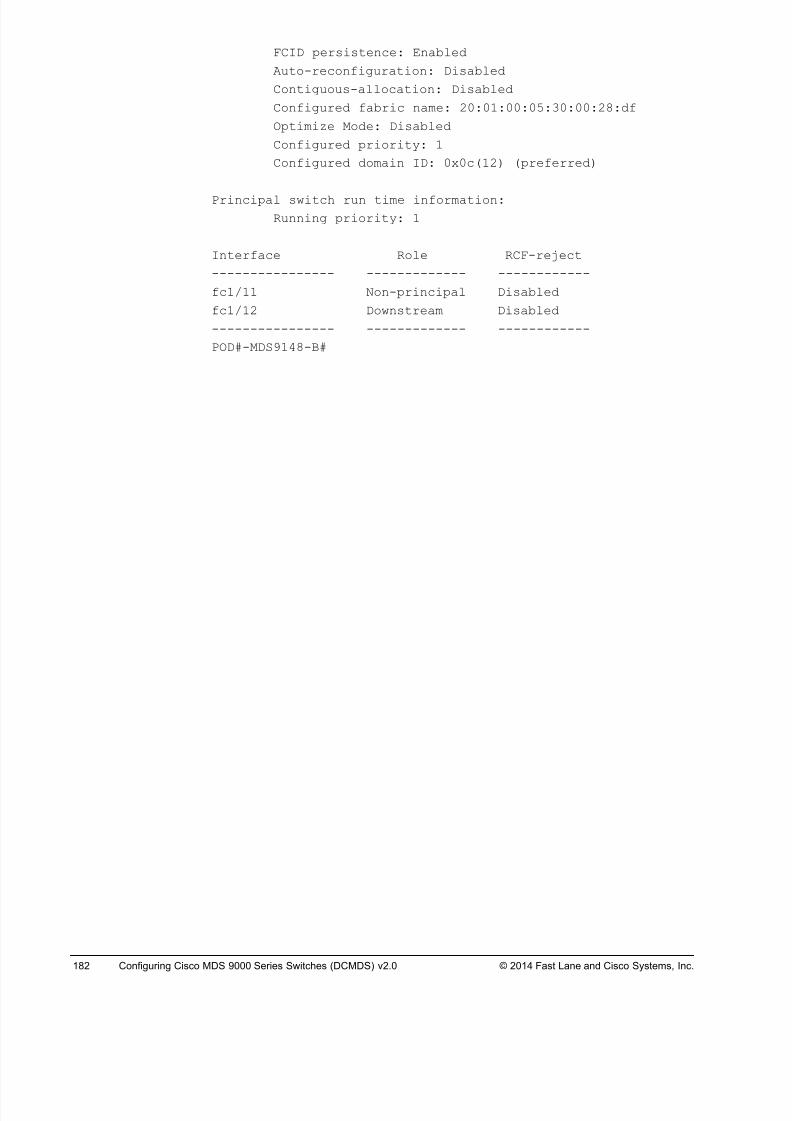
8/18/2019 FL_DCMDS_2.0.3_LG(1).pdf
http://slidepdf.com/reader/full/fldcmds203lg1pdf 182/482
182 Configuring Cisco MDS 9000 Series Switches (DCMDS) v2.0 © 2014 Fast Lane and Cisco Systems, Inc.
FCID persistence: Enabled
Auto-reconfiguration: Disabled
Contiguous-allocation: Disabled
Configured fabric name: 20:01:00:05:30:00:28:df
Optimize Mode: Disabled
Configured priority: 1
Configured domain ID: 0x0c(12) (preferred)
Principal switch run time information:
Running priority: 1
Interface Role RCF-reject
---------------- ------------- ------------
fc1/11 Non-principal Disabled
fc1/12 Downstream Disabled
---------------- ------------- ------------
POD#-MDS9148-B#
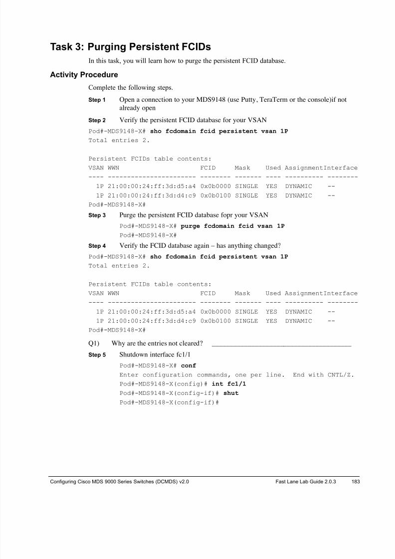
8/18/2019 FL_DCMDS_2.0.3_LG(1).pdf
http://slidepdf.com/reader/full/fldcmds203lg1pdf 183/482
Configuring Cisco MDS 9000 Series Switches (DCMDS) v2.0 Fast Lane Lab Guide 2.0.3 183
Task 3: Purging Persistent FCIDs
In this task, you will learn how to purge the persistent FCID database.
Activity Procedure
Complete the following steps.
Step 1 Open a connection to your MDS9148 (use Putty, TeraTerm or the console)if notalready open
Step 2 Verify the persistent FCID database for your VSAN
Pod#-MDS9148-X# sho fcdomain fcid persistent vsan 1P
Total entries 2.
Persistent FCIDs table contents:
VSAN WWN FCID Mask Used AssignmentInterface
---- ----------------------- -------- ------- ---- ---------- --------
1P 21:00:00:24:ff:3d:d5:a4 0x0b0000 SINGLE YES DYNAMIC --
1P 21:00:00:24:ff:3d:d4:c9 0x0b0100 SINGLE YES DYNAMIC --Pod#-MDS9148-X#
Step 3 Purge the persistent FCID database fopr your VSAN
Pod#-MDS9148-X# purge fcdomain fcid vsan 1P
Pod#-MDS9148-X#
Step 4 Verify the FCID database again – has anything changed?
Pod#-MDS9148-X# sho fcdomain fcid persistent vsan 1P
Total entries 2.
Persistent FCIDs table contents:
VSAN WWN FCID Mask Used AssignmentInterface---- ----------------------- -------- ------- ---- ---------- --------
1P 21:00:00:24:ff:3d:d5:a4 0x0b0000 SINGLE YES DYNAMIC --
1P 21:00:00:24:ff:3d:d4:c9 0x0b0100 SINGLE YES DYNAMIC --
Pod#-MDS9148-X#
Q1) Why are the entries not cleared? _______________________________________
Step 5 Shutdown interface fc1/1
Pod#-MDS9148-X# conf
Enter configuration commands, one per line. End with CNTL/Z.
Pod#-MDS9148-X(config)# int fc1/1
Pod#-MDS9148-X(config-if)# shut
Pod#-MDS9148-X(config-if)#
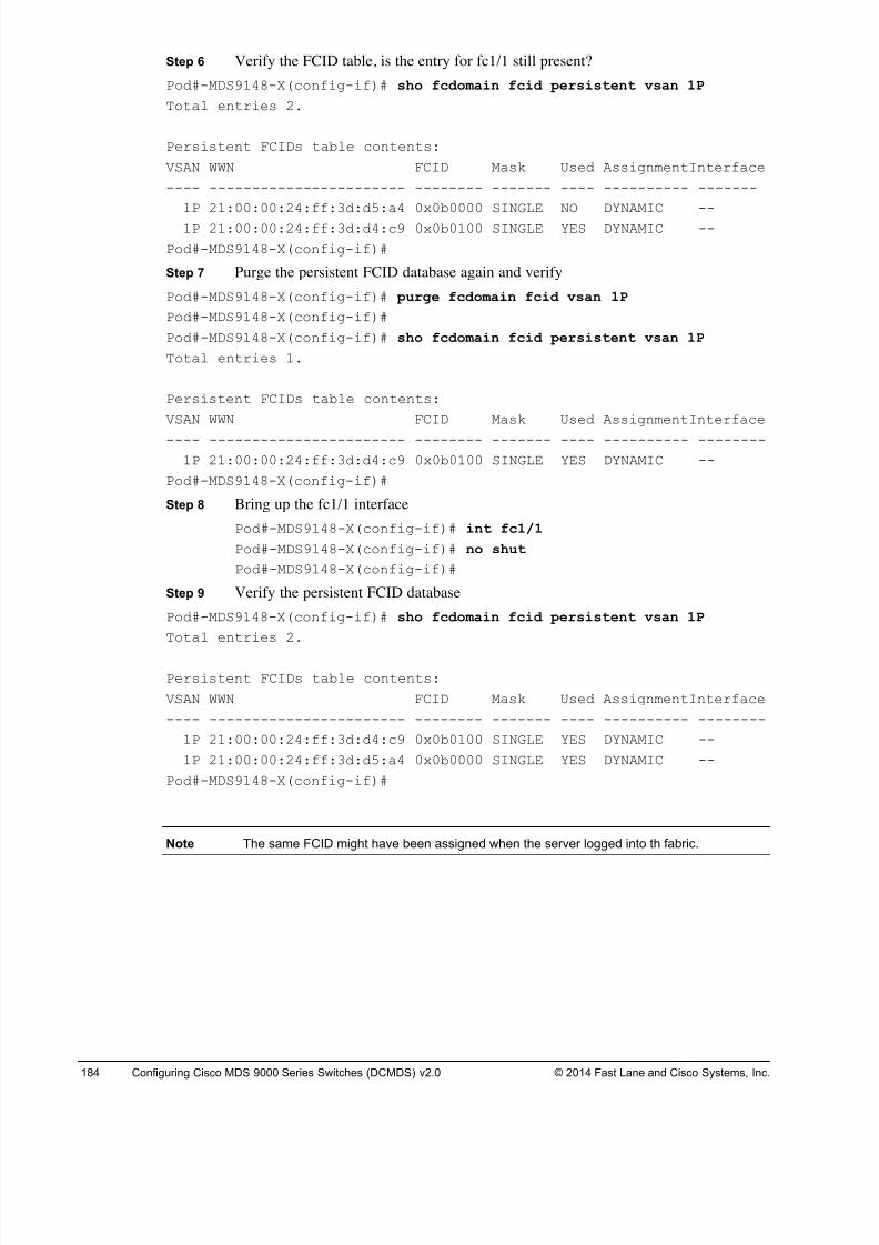
8/18/2019 FL_DCMDS_2.0.3_LG(1).pdf
http://slidepdf.com/reader/full/fldcmds203lg1pdf 184/482
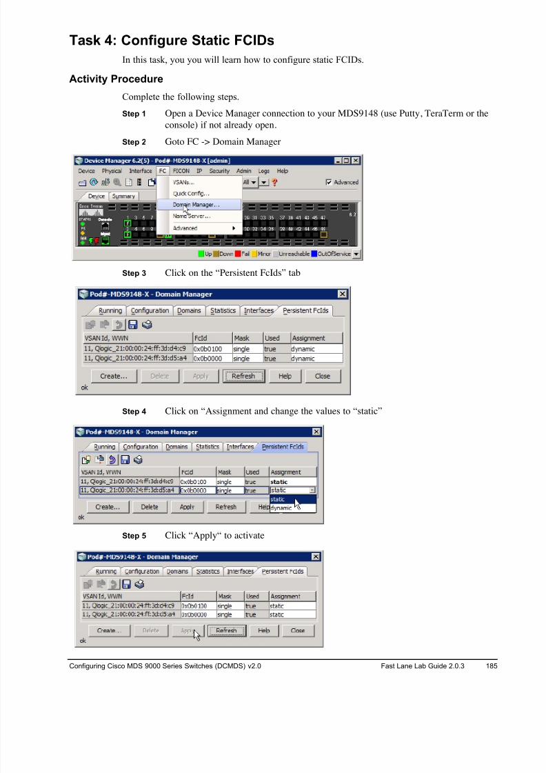
8/18/2019 FL_DCMDS_2.0.3_LG(1).pdf
http://slidepdf.com/reader/full/fldcmds203lg1pdf 185/482
Configuring Cisco MDS 9000 Series Switches (DCMDS) v2.0 Fast Lane Lab Guide 2.0.3 185
Task 4: Configure Static FCIDs
In this task, you you will learn how to configure static FCIDs.
Activity Procedure
Complete the following steps.
Step 1 Open a Device Manager connection to your MDS9148 (use Putty, TeraTerm or the
console) if not already open.
Step 2 Goto FC -> Domain Manager
Step 3 Click on the “Persistent FcIds” tab
Step 4 Click on “Assignment and change the values to “static”
Step 5 Click “Apply“ to activate
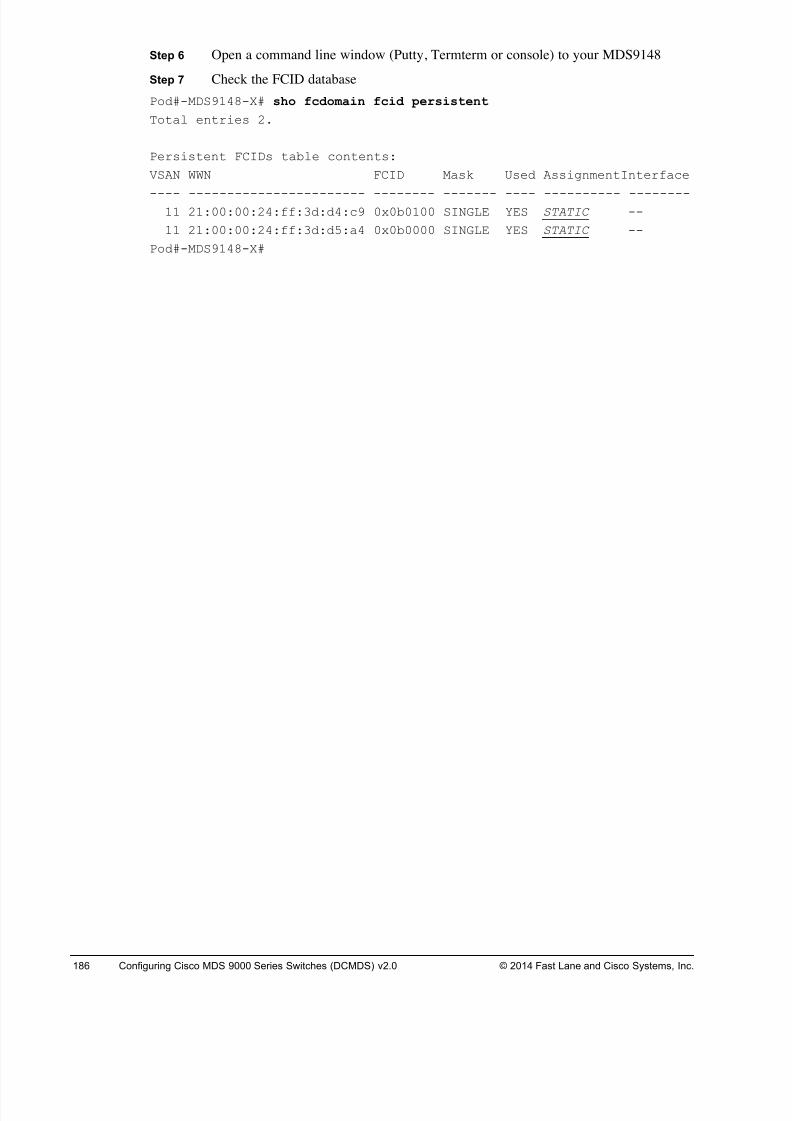
8/18/2019 FL_DCMDS_2.0.3_LG(1).pdf
http://slidepdf.com/reader/full/fldcmds203lg1pdf 186/482
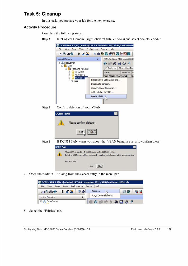
8/18/2019 FL_DCMDS_2.0.3_LG(1).pdf
http://slidepdf.com/reader/full/fldcmds203lg1pdf 187/482

8/18/2019 FL_DCMDS_2.0.3_LG(1).pdf
http://slidepdf.com/reader/full/fldcmds203lg1pdf 188/482

8/18/2019 FL_DCMDS_2.0.3_LG(1).pdf
http://slidepdf.com/reader/full/fldcmds203lg1pdf 189/482
Configuring Cisco MDS 9000 Series Switches (DCMDS) v2.0 Fast Lane Lab Guide 2.0.3 189
14. Clear the current startup configuration ON YOUR 9148s ONLY, DO NOT CLEAR THE CORE
9222is!!! .
# write erase
The following message is displayed:
Warning: This command will erase the startup-configuration.
Do you wish to proceed anyway? [y/n] [N]
Type y to proceed.
15. Reboot the 9148 switch.
# reload
This command will reboot the system. (y/n)?
Type y to proceed.
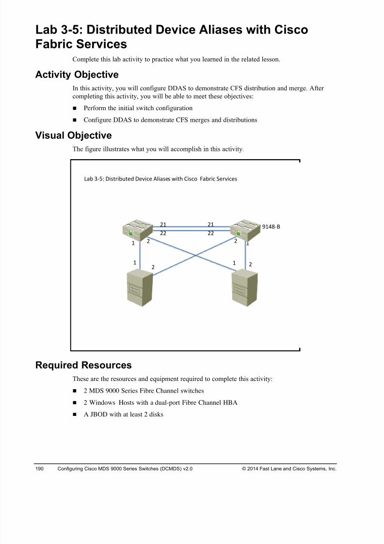
8/18/2019 FL_DCMDS_2.0.3_LG(1).pdf
http://slidepdf.com/reader/full/fldcmds203lg1pdf 190/482
190 Configuring Cisco MDS 9000 Series Switches (DCMDS) v2.0 © 2014 Fast Lane and Cisco Systems, Inc.
Lab 3-5: Distributed Device Aliases with Cisco
Fabric Services Complete this lab activity to practice what you learned in the related lesson.
Activity Objective
In this activity, you will configure DDAS to demonstrate CFS distribution and merge. After
completing this activity, you will be able to meet these objectives:
! Perform the initial switch configuration
! Configure DDAS to demonstrate CFS merges and distributions
Visual Objective
The figure illustrates what you will accomplish in this activity.
Required Resources
These are the resources and equipment required to complete this activity:! 2 MDS 9000 Series Fibre Channel switches
! 2 Windows Hosts with a dual-port Fibre Channel HBA
! A JBOD with at least 2 disks
!"# %&'( )*+,-*#.,/0 )/1*2/ 34*"+/+ 5*,6 7*+28 9"#-*2 :/-1*2/+
; ;< <
<;
<<
<;
<<
;<
<;
=;>?&@
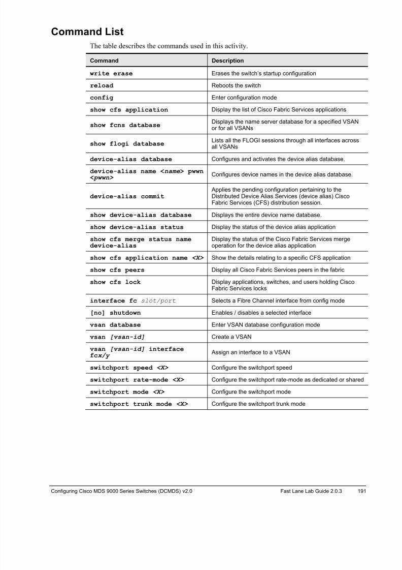
8/18/2019 FL_DCMDS_2.0.3_LG(1).pdf
http://slidepdf.com/reader/full/fldcmds203lg1pdf 191/482
Configuring Cisco MDS 9000 Series Switches (DCMDS) v2.0 Fast Lane Lab Guide 2.0.3 191
Command List
The table describes the commands used in this activity.
Command Description
write erase Erases the switch’s startup configuration
reload Reboots the switch
config Enter configuration mode
show cfs application Display the list of Cisco Fabric Services applications
show fcns databaseDisplays the name server database for a specified VSANor for all VSANs
show flogi databaseLists all the FLOGI sessions through all interfaces acrossall VSANs
device-alias database Configures and activates the device alias database.
device-alias name <name> pwwn < pwwn> Configures device names in the device alias database.
device-alias commit
Applies the pending configuration pertaining to theDistributed Device Alias Services (device alias) CiscoFabric Services (CFS) distribution session.
show device-alias database Displays the entire device name database.
show device-alias status Display the status of the device alias application
show cfs merge status namedevice-alias
Display the status of the Cisco Fabric Services mergeoperation for the device alias application
show cfs application name <X> Show the details relating to a specific CFS application
show cfs peers Display all Cisco Fabric Services peers in the fabric
show cfs lock Display applications, switches, and users holding CiscoFabric Services locks
interface fc slot/port Selects a Fibre Channel interface from config mode
[no] shutdown Enables / disables a selected interface
vsan database Enter VSAN database configuration mode
vsan [vsan-id] Create a VSAN
vsan [vsan-id] interfacefcx/y Assign an interface to a VSAN
switchport speed <X> Configure the switchport speed
switchport rate-mode <X> Configure the switchport rate-mode as dedicated or shared
switchport mode <X> Configure the switchport mode
switchport trunk mode <X> Configure the switchport trunk mode
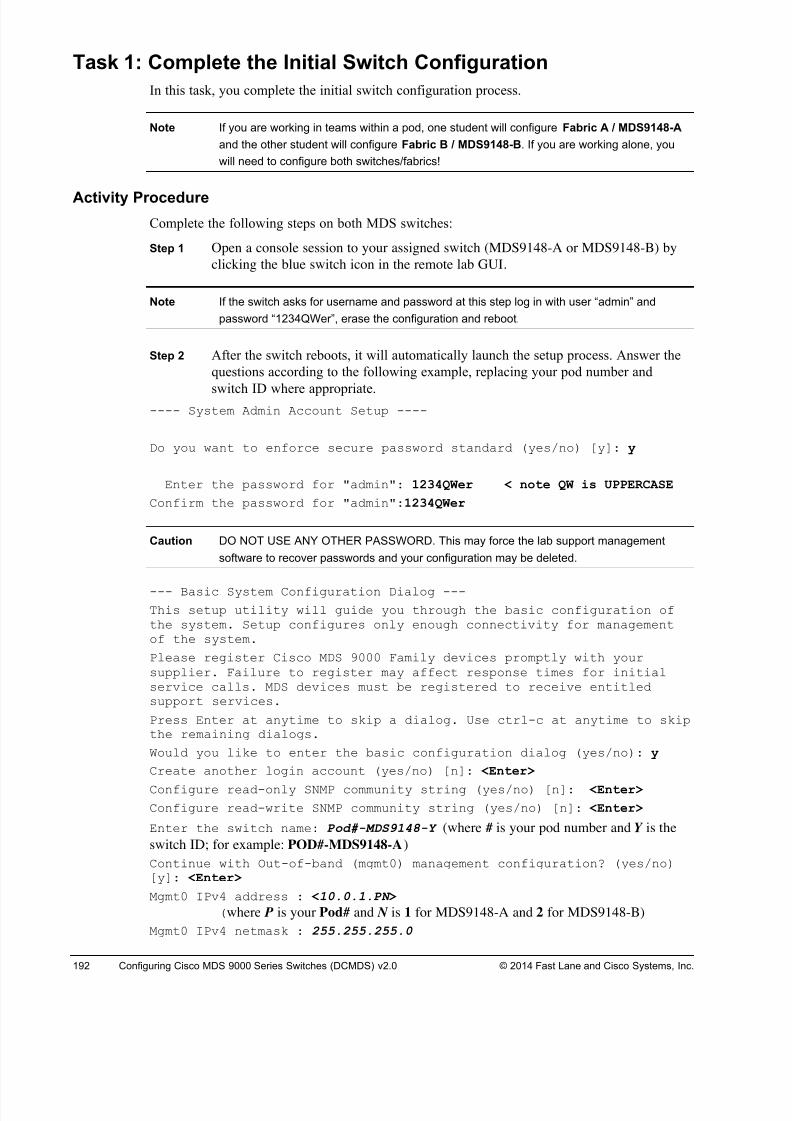
8/18/2019 FL_DCMDS_2.0.3_LG(1).pdf
http://slidepdf.com/reader/full/fldcmds203lg1pdf 192/482
192 Configuring Cisco MDS 9000 Series Switches (DCMDS) v2.0 © 2014 Fast Lane and Cisco Systems, Inc.
Task 1: Complete the Initial Switch Configuration
In this task, you complete the initial switch configuration process.
Note If you are working in teams within a pod, one student will configure Fabric A / MDS9148-A
and the other student will configure Fabric B / MDS9148-B. If you are working alone, you
will need to configure both switches/fabrics!
Activity Procedure
Complete the following steps on both MDS switches:
Step 1 Open a console session to your assigned switch (MDS9148-A or MDS9148-B) by
clicking the blue switch icon in the remote lab GUI.
Note If the switch asks for username and password at this step log in with user “admin” and
password “1234QWer”, erase the configuration and reboot.
Step 2 After the switch reboots, it will automatically launch the setup process. Answer the
questions according to the following example, replacing your pod number and
switch ID where appropriate.---- System Admin Account Setup ----
Do you want to enforce secure password standard (yes/no) [y]: y
Enter the password for "admin": 1234QWer < note QW is UPPERCASE
Confirm the password for "admin":1234QWer
Caution DO NOT USE ANY OTHER PASSWORD. This may force the lab support management
software to recover passwords and your configuration may be deleted.
--- Basic System Configuration Dialog ---
This setup utility will guide you through the basic configuration ofthe system. Setup configures only enough connectivity for managementof the system.
Please register Cisco MDS 9000 Family devices promptly with yoursupplier. Failure to register may affect response times for initialservice calls. MDS devices must be registered to receive entitledsupport services.
Press Enter at anytime to skip a dialog. Use ctrl-c at anytime to skipthe remaining dialogs.
Would you like to enter the basic configuration dialog (yes/no): y
Create another login account (yes/no) [n]: <Enter>
Configure read-only SNMP community string (yes/no) [n]: <Enter>
Configure read-write SNMP community string (yes/no) [n]: <Enter>
Enter the switch name: Pod#-MDS9148-Y (where # is your pod number and Y is the
switch ID; for example: POD#-MDS9148-A)
Continue with Out-of-band (mgmt0) management configuration? (yes/no)[y]: <Enter>
Mgmt0 IPv4 address : <10.0.1.PN >
(where P is your Pod# and N is 1 for MDS9148-A and 2 for MDS9148-B)
Mgmt0 IPv4 netmask : 255.255.255.0
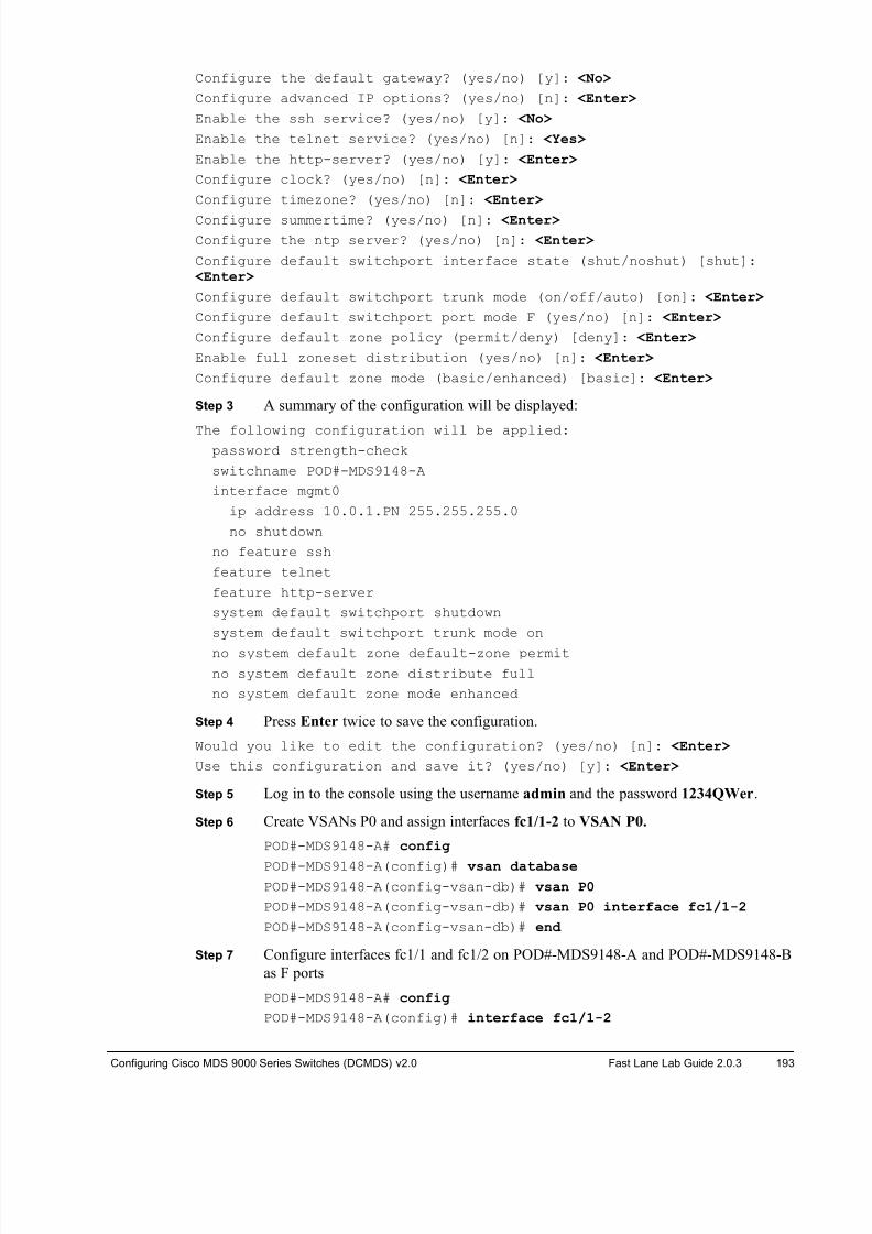
8/18/2019 FL_DCMDS_2.0.3_LG(1).pdf
http://slidepdf.com/reader/full/fldcmds203lg1pdf 193/482
Configuring Cisco MDS 9000 Series Switches (DCMDS) v2.0 Fast Lane Lab Guide 2.0.3 193
Configure the default gateway? (yes/no) [y]: <No>
Configure advanced IP options? (yes/no) [n]: <Enter>
Enable the ssh service? (yes/no) [y]: <No>
Enable the telnet service? (yes/no) [n]: <Yes>
Enable the http-server? (yes/no) [y]: <Enter>
Configure clock? (yes/no) [n]: <Enter>
Configure timezone? (yes/no) [n]: <Enter>
Configure summertime? (yes/no) [n]: <Enter>
Configure the ntp server? (yes/no) [n]: <Enter>
Configure default switchport interface state (shut/noshut) [shut]: <Enter>
Configure default switchport trunk mode (on/off/auto) [on]: <Enter>
Configure default switchport port mode F (yes/no) [n]: <Enter>
Configure default zone policy (permit/deny) [deny]: <Enter>
Enable full zoneset distribution (yes/no) [n]: <Enter>
Configure default zone mode (basic/enhanced) [basic]: <Enter>
Step 3 A summary of the configuration will be displayed:
The following configuration will be applied:password strength-check
switchname POD#-MDS9148-A
interface mgmt0
ip address 10.0.1.PN 255.255.255.0
no shutdown
no feature ssh
feature telnet
feature http-server
system default switchport shutdown
system default switchport trunk mode on
no system default zone default-zone permit
no system default zone distribute full
no system default zone mode enhanced
Step 4 Press Enter twice to save the configuration.
Would you like to edit the configuration? (yes/no) [n]: <Enter>
Use this configuration and save it? (yes/no) [y]: <Enter>
Step 5 Log in to the console using the username admin and the password 1234QWer.
Step 6 Create VSANs P0 and assign interfaces fc1/1-2 to VSAN P0.
POD#-MDS9148-A# config
POD#-MDS9148-A(config)# vsan database POD#-MDS9148-A(config-vsan-db)# vsan P0
POD#-MDS9148-A(config-vsan-db)# vsan P0 interface fc1/1-2
POD#-MDS9148-A(config-vsan-db)# end
Step 7 Configure interfaces fc1/1 and fc1/2 on POD#-MDS9148-A and POD#-MDS9148-B
as F ports
POD#-MDS9148-A# config
POD#-MDS9148-A(config)# interface fc1/1-2
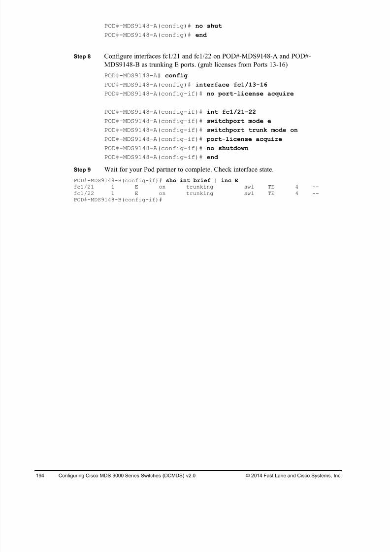
8/18/2019 FL_DCMDS_2.0.3_LG(1).pdf
http://slidepdf.com/reader/full/fldcmds203lg1pdf 194/482
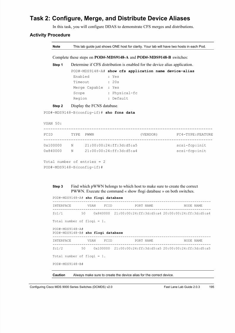
8/18/2019 FL_DCMDS_2.0.3_LG(1).pdf
http://slidepdf.com/reader/full/fldcmds203lg1pdf 195/482
Configuring Cisco MDS 9000 Series Switches (DCMDS) v2.0 Fast Lane Lab Guide 2.0.3 195
Task 2: Configure, Merge, and Distribute Device Aliases
In this task, you will configure DDAS to demonstrate CFS merges and distributions.
Activity Procedure
Note This lab guide just shows ONE host for clarity. Your lab will have two hosts in each Pod.
Complete these steps on POD#-MDS9148-A and POD#-MDS9148-B switches:Step 1 Determine if CFS distribution is enabled for the device alias application.
POD#-MDS9148-A# show cfs application name device-alias
Enabled : Yes
Timeout : 20s
Merge Capable : Yes
Scope : Physical-fc
Region : Default
Step 2 Display the FCNS database.
POD#-MDS9148-B(config-if)# sho fcns data
VSAN 50:
--------------------------------------------------------------------------
FCID TYPE PWWN (VENDOR) FC4-TYPE:FEATURE
--------------------------------------------------------------------------
0x100000 N 21:00:00:24:ff:3d:d5:a5 scsi-fcp:init
0x840000 N 21:00:00:24:ff:3d:d5:a4 scsi-fcp:init
Total number of entries = 2
POD#-MDS9148-B(config-if)#
Step 3 Find which pWWN belongs to which host to make sure to create the correct
PWWN. Execute the command « show flogi database » on both switches.
POD#-MDS9148-A# sho flogi database -----------------------------------------------------------------------------INTERFACE VSAN FCID PORT NAME NODE NAME-----------------------------------------------------------------------------fc1/1 50 0x840000 21:00:00:24:ff:3d:d5:a4 20:00:00:24:ff:3d:d5:a4
Total number of flogi = 1.
POD#-MDS9148-A#
POD#-MDS9148-B# sho flogi database -----------------------------------------------------------------------------INTERFACE VSAN FCID PORT NAME NODE NAME-----------------------------------------------------------------------------fc1/2 50 0x100000 21:00:00:24:ff:3d:d5:a5 20:00:00:24:ff:3d:d5:a5
Total number of flogi = 1.
POD#-MDS9148-B#
Caution Always make sure to create the device alias for the correct device.
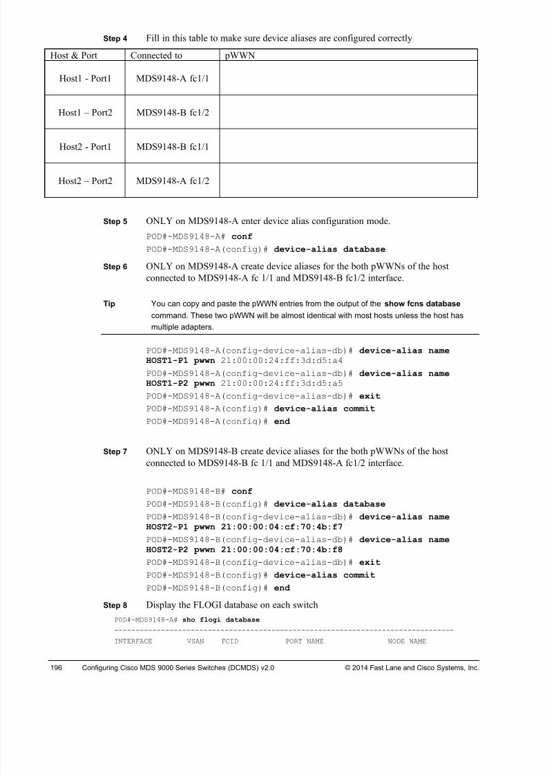
8/18/2019 FL_DCMDS_2.0.3_LG(1).pdf
http://slidepdf.com/reader/full/fldcmds203lg1pdf 196/482
196 Configuring Cisco MDS 9000 Series Switches (DCMDS) v2.0 © 2014 Fast Lane and Cisco Systems, Inc.
Step 4 Fill in this table to make sure device aliases are configured correctly
Host & Port Connected to pWWN
Host1 - Port1 MDS9148-A fc1/1
Host1 – Port2 MDS9148-B fc1/2
Host2 - Port1 MDS9148-B fc1/1
Host2 – Port2 MDS9148-A fc1/2
Step 5 ONLY on MDS9148-A enter device alias configuration mode.
POD#-MDS9148-A# conf
POD#-MDS9148-A(config)# device-alias database
Step 6 ONLY on MDS9148-A create device aliases for the both pWWNs of the host
connected to MDS9148-A fc 1/1 and MDS9148-B fc1/2 interface.
Tip You can copy and paste the pWWN entries from the output of the show fcns database
command. These two pWWN will be almost identical with most hosts unless the host has
multiple adapters.
POD#-MDS9148-A(config-device-alias-db)# device-alias nameHOST1-P1 pwwn 21:00:00:24:ff:3d:d5:a4
POD#-MDS9148-A(config-device-alias-db)# device-alias nameHOST1-P2 pwwn 21:00:00:24:ff:3d:d5:a5
POD#-MDS9148-A(config-device-alias-db)# exit
POD#-MDS9148-A(config)# device-alias commit POD#-MDS9148-A(config)# end
Step 7 ONLY on MDS9148-B create device aliases for the both pWWNs of the host
connected to MDS9148-B fc 1/1 and MDS9148-A fc1/2 interface.
POD#-MDS9148-B# conf
POD#-MDS9148-B(config)# device-alias database
POD#-MDS9148-B(config-device-alias-db)# device-alias nameHOST2-P1 pwwn 21:00:00:04:cf:70:4b:f7
POD#-MDS9148-B(config-device-alias-db)# device-alias nameHOST2-P2 pwwn 21:00:00:04:cf:70:4b:f8
POD#-MDS9148-B(config-device-alias-db)# exit
POD#-MDS9148-B(config)# device-alias commit
POD#-MDS9148-B(config)# end
Step 8 Display the FLOGI database on each switch
POD#-MDS9148-A# sho flogi database
--------------------------------------------------------------------------------
INTERFACE VSAN FCID PORT NAME NODE NAME
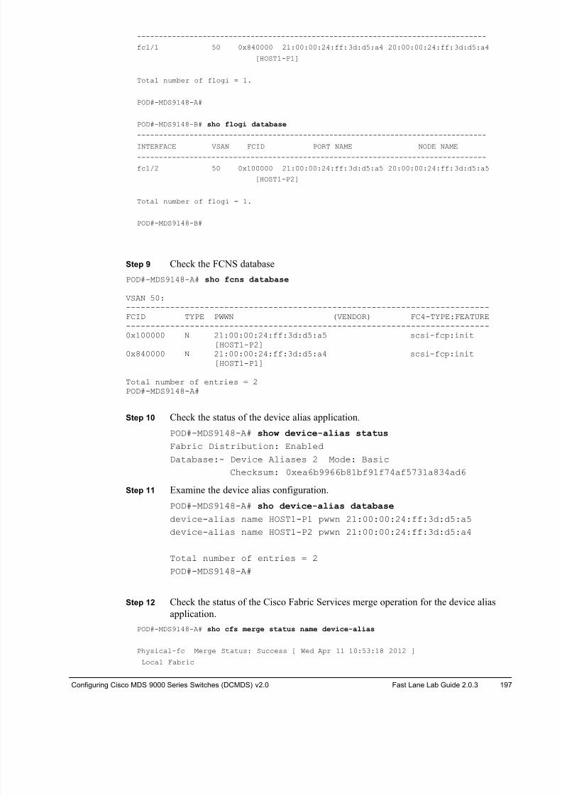
8/18/2019 FL_DCMDS_2.0.3_LG(1).pdf
http://slidepdf.com/reader/full/fldcmds203lg1pdf 197/482
Configuring Cisco MDS 9000 Series Switches (DCMDS) v2.0 Fast Lane Lab Guide 2.0.3 197
--------------------------------------------------------------------------------
fc1/1 50 0x840000 21:00:00:24:ff:3d:d5:a4 20:00:00:24:ff:3d:d5:a4
[HOST1-P1]
Total number of flogi = 1.
POD#-MDS9148-A#
POD#-MDS9148-B# sho flogi database
--------------------------------------------------------------------------------INTERFACE VSAN FCID PORT NAME NODE NAME
--------------------------------------------------------------------------------
fc1/2 50 0x100000 21:00:00:24:ff:3d:d5:a5 20:00:00:24:ff:3d:d5:a5
[HOST1-P2]
Total number of flogi = 1.
POD#-MDS9148-B#
Step 9 Check the FCNS database
POD#-MDS9148-A# sho fcns database
VSAN 50:--------------------------------------------------------------------------FCID TYPE PWWN (VENDOR) FC4-TYPE:FEATURE--------------------------------------------------------------------------0x100000 N 21:00:00:24:ff:3d:d5:a5 scsi-fcp:init
[HOST1-P2]0x840000 N 21:00:00:24:ff:3d:d5:a4 scsi-fcp:init
[HOST1-P1]
Total number of entries = 2POD#-MDS9148-A#
Step 10 Check the status of the device alias application.POD#-MDS9148-A# show device-alias status
Fabric Distribution: Enabled
Database:- Device Aliases 2 Mode: Basic
Checksum: 0xea6b9966b81bf91f74af5731a834ad6
Step 11 Examine the device alias configuration.
POD#-MDS9148-A# sho device-alias database
device-alias name HOST1-P1 pwwn 21:00:00:24:ff:3d:d5:a5
device-alias name HOST1-P2 pwwn 21:00:00:24:ff:3d:d5:a4
Total number of entries = 2POD#-MDS9148-A#
Step 12 Check the status of the Cisco Fabric Services merge operation for the device alias
application.
POD#-MDS9148-A# sho cfs merge status name device-alias
Physical-fc Merge Status: Success [ Wed Apr 11 10:53:18 2012 ]
Local Fabric
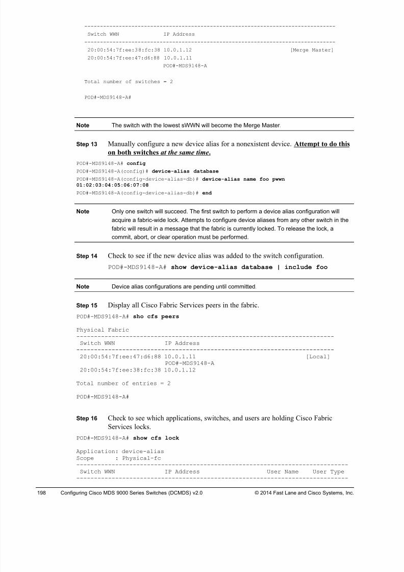
8/18/2019 FL_DCMDS_2.0.3_LG(1).pdf
http://slidepdf.com/reader/full/fldcmds203lg1pdf 198/482
198 Configuring Cisco MDS 9000 Series Switches (DCMDS) v2.0 © 2014 Fast Lane and Cisco Systems, Inc.
--------------------------------------------------------------------------------
Switch WWN IP Address
--------------------------------------------------------------------------------
20:00:54:7f:ee:38:fc:38 10.0.1.12 [Merge Master]
20:00:54:7f:ee:47:d6:88 10.0.1.11
POD#-MDS9148-A
Total number of switches = 2
POD#-MDS9148-A#
Note The switch with the lowest sWWN will become the Merge Master.
Step 13 Manually configure a new device alias for a nonexistent device. Attempt to do this
on both switches at the same time.
POD#-MDS9148-A# config
POD#-MDS9148-A(config)# device-alias database
POD#-MDS9148-A(config-device-alias-db)# device-alias name foo pwwn01:02:03:04:05:06:07:08
POD#-MDS9148-A(config-device-alias-db)# end
Note Only one switch will succeed. The first switch to perform a device alias configuration will
acquire a fabric-wide lock. Attempts to configure device aliases from any other switch in the
fabric will result in a message that the fabric is currently locked. To release the lock, a
commit, abort, or clear operation must be performed.
Step 14 Check to see if the new device alias was added to the switch configuration.
POD#-MDS9148-A# show device-alias database | include foo
Note Device alias configurations are pending until committed.
Step 15 Display all Cisco Fabric Services peers in the fabric.
POD#-MDS9148-A# sho cfs peers
Physical Fabric-------------------------------------------------------------------------Switch WWN IP Address
-------------------------------------------------------------------------20:00:54:7f:ee:47:d6:88 10.0.1.11 [Local]
POD#-MDS9148-A20:00:54:7f:ee:38:fc:38 10.0.1.12
Total number of entries = 2
POD#-MDS9148-A#
Step 16 Check to see which applications, switches, and users are holding Cisco Fabric
Services locks.
POD#-MDS9148-A# show cfs lock
Application: device-aliasScope : Physical-fc-----------------------------------------------------------------------------Switch WWN IP Address User Name User Type
-----------------------------------------------------------------------------
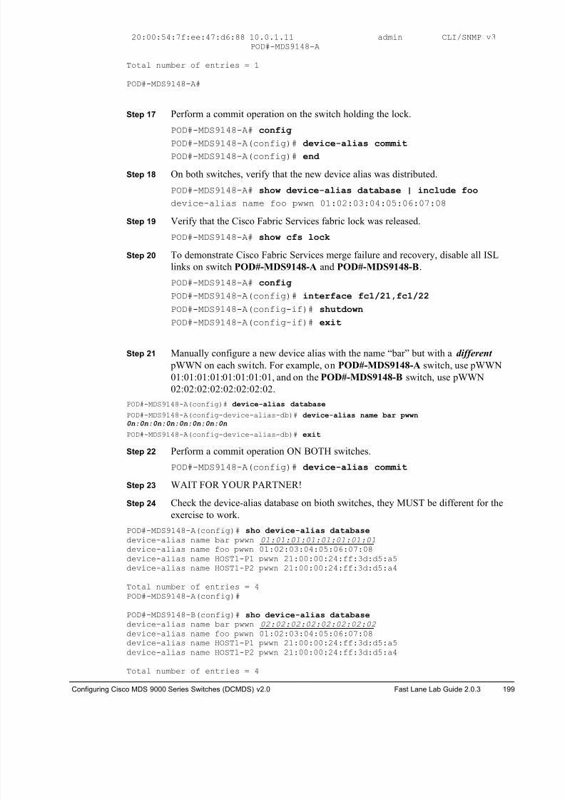
8/18/2019 FL_DCMDS_2.0.3_LG(1).pdf
http://slidepdf.com/reader/full/fldcmds203lg1pdf 199/482
Configuring Cisco MDS 9000 Series Switches (DCMDS) v2.0 Fast Lane Lab Guide 2.0.3 199
20:00:54:7f:ee:47:d6:88 10.0.1.11 admin CLI/SNMP v3POD#-MDS9148-A
Total number of entries = 1
POD#-MDS9148-A#
Step 17 Perform a commit operation on the switch holding the lock.
POD#-MDS9148-A# config
POD#-MDS9148-A(config)# device-alias commit
POD#-MDS9148-A(config)# end
Step 18 On both switches, verify that the new device alias was distributed.
POD#-MDS9148-A# show device-alias database | include foo
device-alias name foo pwwn 01:02:03:04:05:06:07:08
Step 19 Verify that the Cisco Fabric Services fabric lock was released.
POD#-MDS9148-A# show cfs lock
Step 20 To demonstrate Cisco Fabric Services merge failure and recovery, disable all ISL
links on switch POD#-MDS9148-A and POD#-MDS9148-B.
POD#-MDS9148-A# config
POD#-MDS9148-A(config)# interface fc1/21,fc1/22
POD#-MDS9148-A(config-if)# shutdown
POD#-MDS9148-A(config-if)# exit
Step 21 Manually configure a new device alias with the name “bar” but with a different
pWWN on each switch. For example, on POD#-MDS9148-A switch, use pWWN
01:01:01:01:01:01:01:01, and on the POD#-MDS9148-B switch, use pWWN
02:02:02:02:02:02:02:02.
POD#-MDS9148-A(config)# device-alias database
POD#-MDS9148-A(config-device-alias-db)# device-alias name bar pwwn0n:0n:0n:0n:0n:0n:0n:0n
POD#-MDS9148-A(config-device-alias-db)# exit
Step 22 Perform a commit operation ON BOTH switches.
POD#-MDS9148-A(config)# device-alias commit
Step 23 WAIT FOR YOUR PARTNER!
Step 24 Check the device-alias database on bioth switches, they MUST be different for the
exercise to work.
POD#-MDS9148-A(config)# sho device-alias database
device-alias name bar pwwn 01:01:01:01:01:01:01:01 device-alias name foo pwwn 01:02:03:04:05:06:07:08
device-alias name HOST1-P1 pwwn 21:00:00:24:ff:3d:d5:a5device-alias name HOST1-P2 pwwn 21:00:00:24:ff:3d:d5:a4
Total number of entries = 4POD#-MDS9148-A(config)#
POD#-MDS9148-B(config)# sho device-alias database
device-alias name bar pwwn 02:02:02:02:02:02:02:02 device-alias name foo pwwn 01:02:03:04:05:06:07:08device-alias name HOST1-P1 pwwn 21:00:00:24:ff:3d:d5:a5device-alias name HOST1-P2 pwwn 21:00:00:24:ff:3d:d5:a4
Total number of entries = 4
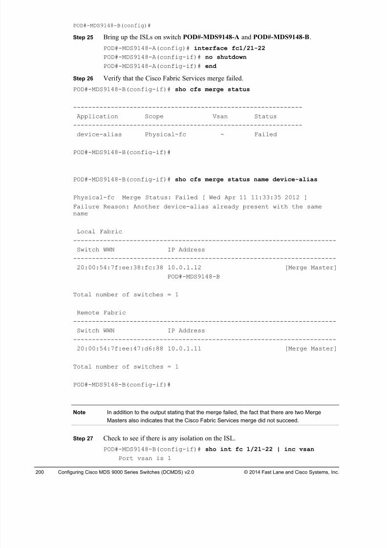
8/18/2019 FL_DCMDS_2.0.3_LG(1).pdf
http://slidepdf.com/reader/full/fldcmds203lg1pdf 200/482
200 Configuring Cisco MDS 9000 Series Switches (DCMDS) v2.0 © 2014 Fast Lane and Cisco Systems, Inc.
POD#-MDS9148-B(config)#
Step 25 Bring up the ISLs on switch POD#-MDS9148-A and POD#-MDS9148-B.
POD#-MDS9148-A(config)# interface fc1/21-22
POD#-MDS9148-A(config-if)# no shutdown
POD#-MDS9148-A(config-if)# end
Step 26 Verify that the Cisco Fabric Services merge failed.
POD#-MDS9148-B(config-if)# sho cfs merge status
-------------------------------------------------------------
Application Scope Vsan Status
-------------------------------------------------------------
device-alias Physical-fc - Failed
POD#-MDS9148-B(config-if)#
POD#-MDS9148-B(config-if)# sho cfs merge status name device-alias
Physical-fc Merge Status: Failed [ Wed Apr 11 11:33:35 2012 ]
Failure Reason: Another device-alias already present with the samename
Local Fabric
----------------------------------------------------------------------
Switch WWN IP Address
----------------------------------------------------------------------
20:00:54:7f:ee:38:fc:38 10.0.1.12 [Merge Master]
POD#-MDS9148-B
Total number of switches = 1
Remote Fabric
----------------------------------------------------------------------
Switch WWN IP Address
----------------------------------------------------------------------
20:00:54:7f:ee:47:d6:88 10.0.1.11 [Merge Master]
Total number of switches = 1
POD#-MDS9148-B(config-if)#
Note In addition to the output stating that the merge failed, the fact that there are two Merge
Masters also indicates that the Cisco Fabric Services merge did not succeed.
Step 27 Check to see if there is any isolation on the ISL.
POD#-MDS9148-B(config-if)# sho int fc 1/21-22 | inc vsan
Port vsan is 1
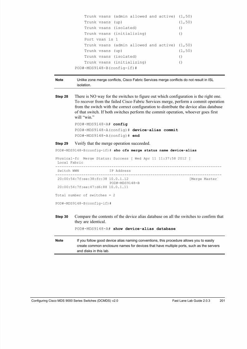
8/18/2019 FL_DCMDS_2.0.3_LG(1).pdf
http://slidepdf.com/reader/full/fldcmds203lg1pdf 201/482
Configuring Cisco MDS 9000 Series Switches (DCMDS) v2.0 Fast Lane Lab Guide 2.0.3 201
Trunk vsans (admin allowed and active) (1,50)
Trunk vsans (up) (1,50)
Trunk vsans (isolated) ()
Trunk vsans (initializing) ()
Port vsan is 1
Trunk vsans (admin allowed and active) (1,50)
Trunk vsans (up) (1,50)
Trunk vsans (isolated) ()
Trunk vsans (initializing) ()
POD#-MDS9148-B(config-if)#
Note Unlike zone merge conflicts, Cisco Fabric Services merge conflicts do not result in ISL
isolation.
Step 28 There is NO way for the switches to figure out which configuration is the right one.
To recover from the failed Cisco Fabric Services merge, perform a commit operation
from the switch with the correct configuration to distribute the device alias database
of that switch. If both switches perform the commit operation, whoever goes first
will “win.”
POD#-MDS9148-A# config
POD#-MDS9148-A(config)# device-alias commit
POD#-MDS9148-A(config)# end
Step 29 Verify that the merge operation succeeded.
POD#-MDS9148-B(config-if)# sho cfs merge status name device-alias
Physical-fc Merge Status: Success [ Wed Apr 11 11:37:58 2012 ]Local Fabric
-----------------------------------------------------------------------------Switch WWN IP Address
-----------------------------------------------------------------------------20:00:54:7f:ee:38:fc:38 10.0.1.12 [Merge Master]
POD#-MDS9148-B20:00:54:7f:ee:47:d6:88 10.0.1.11
Total number of switches = 2
POD#-MDS9148-B(config-if)#
Step 30 Compare the contents of the device alias database on all the switches to confirm that
they are identical.
POD#-MDS9148-A# show device-alias database
Note If you follow good device alias naming conventions, this procedure allows you to easily
create common enclosure names for devices that have multiple ports, such as the servers
and disks in this lab.
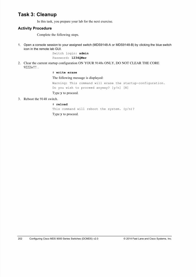
8/18/2019 FL_DCMDS_2.0.3_LG(1).pdf
http://slidepdf.com/reader/full/fldcmds203lg1pdf 202/482
202 Configuring Cisco MDS 9000 Series Switches (DCMDS) v2.0 © 2014 Fast Lane and Cisco Systems, Inc.
Task 3: Cleanup
In this task, you prepare your lab for the next exercise.
Activity Procedure
Complete the following steps.
1. Open a console session to your assigned switch (MDS9148-A or MDS9148-B) by clicking the blue switch
icon in the remote lab GUI.Switch login: admin
Password: 1234QWer
2. Clear the current startup configuration ON YOUR 9148s ONLY, DO NOT CLEAR THE CORE
9222is!!! .
# write erase
The following message is displayed:
Warning: This command will erase the startup-configuration.
Do you wish to proceed anyway? [y/n] [N]
Type y to proceed.
3. Reboot the 9148 switch.
# reload
This command will reboot the system. (y/n)?
Type y to proceed.
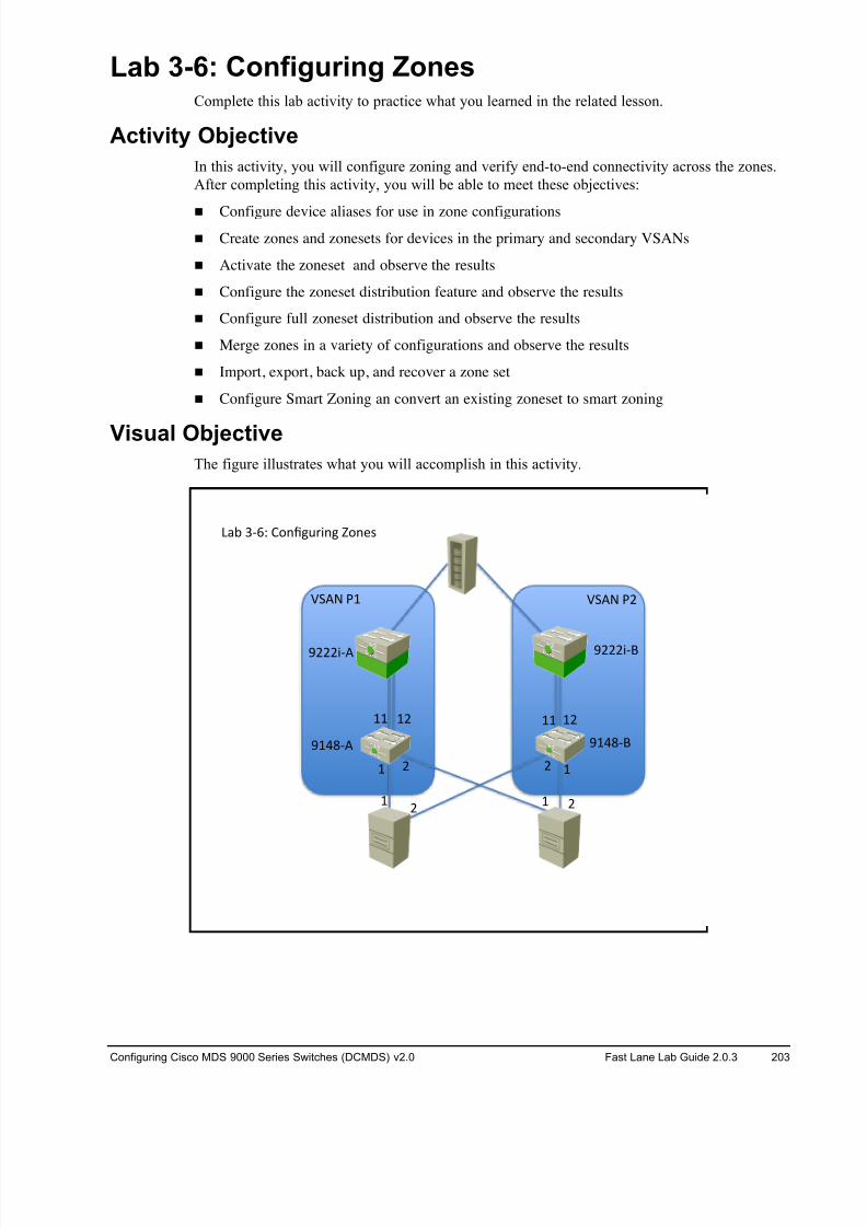
8/18/2019 FL_DCMDS_2.0.3_LG(1).pdf
http://slidepdf.com/reader/full/fldcmds203lg1pdf 203/482
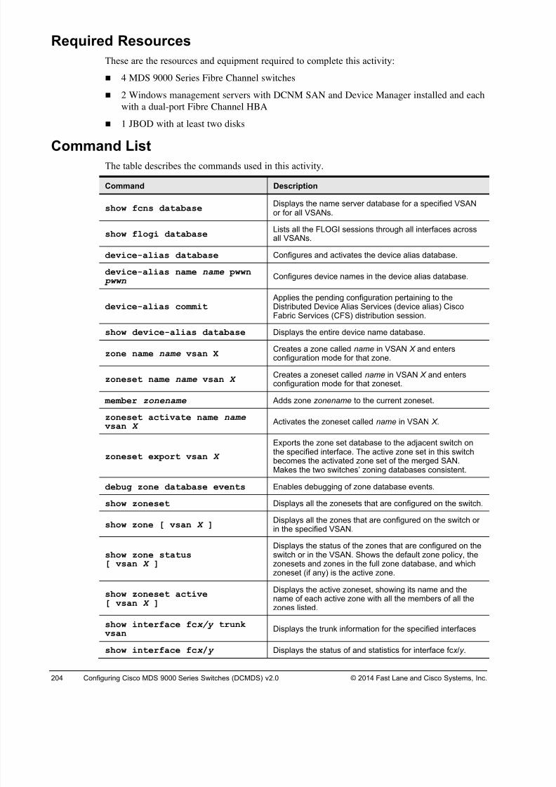
8/18/2019 FL_DCMDS_2.0.3_LG(1).pdf
http://slidepdf.com/reader/full/fldcmds203lg1pdf 204/482
204 Configuring Cisco MDS 9000 Series Switches (DCMDS) v2.0 © 2014 Fast Lane and Cisco Systems, Inc.
Required Resources
These are the resources and equipment required to complete this activity:
! 4 MDS 9000 Series Fibre Channel switches
! 2 Windows management servers with DCNM SAN and Device Manager installed and each
with a dual-port Fibre Channel HBA
! 1 JBOD with at least two disks
Command List
The table describes the commands used in this activity.
Command Description
show fcns databaseDisplays the name server database for a specified VSANor for all VSANs.
show flogi databaseLists all the FLOGI sessions through all interfaces acrossall VSANs.
device-alias database Configures and activates the device alias database.
device-alias name name pwwn pwwn Configures device names in the device alias database.
device-alias commit Applies the pending configuration pertaining to theDistributed Device Alias Services (device alias) CiscoFabric Services (CFS) distribution session.
show device-alias database Displays the entire device name database.
zone name name vsan X Creates a zone called name in VSAN X and entersconfiguration mode for that zone.
zoneset name name vsan X Creates a zoneset called name in VSAN X and entersconfiguration mode for that zoneset.
member zonename Adds zone zonename to the current zoneset.
zoneset activate name name vsan X Activates the zoneset called name in VSAN X.
zoneset export vsan X
Exports the zone set database to the adjacent switch onthe specified interface. The active zone set in this switchbecomes the activated zone set of the merged SAN.Makes the two switches’ zoning databases consistent.
debug zone database events Enables debugging of zone database events.
show zoneset Displays all the zonesets that are configured on the switch.
show zone [ vsan X ] Displays all the zones that are configured on the switch orin the specified VSAN.
show zone status[ vsan X ]
Displays the status of the zones that are configured on theswitch or in the VSAN. Shows the default zone policy, thezonesets and zones in the full zone database, and whichzoneset (if any) is the active zone.
show zoneset active[ vsan X ]
Displays the active zoneset, showing its name and thename of each active zone with all the members of all thezones listed.
show interface fcx/y trunkvsan
Displays the trunk information for the specified interfaces
show interface fcx / y Displays the status of and statistics for interface fc x /y .
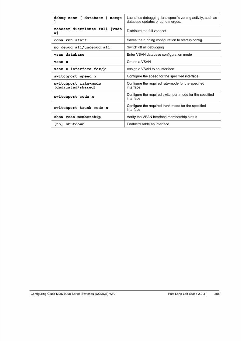
8/18/2019 FL_DCMDS_2.0.3_LG(1).pdf
http://slidepdf.com/reader/full/fldcmds203lg1pdf 205/482

8/18/2019 FL_DCMDS_2.0.3_LG(1).pdf
http://slidepdf.com/reader/full/fldcmds203lg1pdf 206/482
206 Configuring Cisco MDS 9000 Series Switches (DCMDS) v2.0 © 2014 Fast Lane and Cisco Systems, Inc.
Task 1: Complete the Initial Switch Configuration
In this task, you complete the initial switch configuration process.
Note If you are working in teams within a pod, one student will configure Fabric A / MDS9148-A
and the other student will configure Fabric B / MDS9148-B. If you are working alone, you
will need to configure both switches/fabrics!
Activity Procedure
Complete the following steps on both MDS switches:
Step 31 Open a console session to your assigned switch (MDS9148-A or MDS9148-B) by
clicking the blue switch icon in the remote lab GUI.
Note If the switch asks for username and password at this step log in with user “admin” and
password “1234QWer”, erase the configuration and reboot.
Step 32 After the switch reboots, it will automatically launch the setup process. Answer the
questions according to the following example, replacing your pod number and
switch ID where appropriate.---- System Admin Account Setup ----
Do you want to enforce secure password standard (yes/no) [y]: y
Enter the password for "admin": 1234QWer < note QW is UPPERCASE
Confirm the password for "admin":1234QWer
Caution DO NOT USE ANY OTHER PASSWORD. This may force the lab support management
software to recover passwords and your configuration may be deleted.
--- Basic System Configuration Dialog ---
This setup utility will guide you through the basic configuration ofthe system. Setup configures only enough connectivity for managementof the system.
Please register Cisco MDS 9000 Family devices promptly with yoursupplier. Failure to register may affect response times for initialservice calls. MDS devices must be registered to receive entitledsupport services.
Press Enter at anytime to skip a dialog. Use ctrl-c at anytime to skipthe remaining dialogs.
Would you like to enter the basic configuration dialog (yes/no): y
Create another login account (yes/no) [n]: <Enter>
Configure read-only SNMP community string (yes/no) [n]: <Enter>
Configure read-write SNMP community string (yes/no) [n]: <Enter>
Enter the switch name: Pod#-MDS9148-Y (where # is your pod number and Y is the
switch ID; for example: POD#-MDS9148-A)
Continue with Out-of-band (mgmt0) management configuration? (yes/no)[y]: <Enter>
Mgmt0 IPv4 address : <10.0.1.PN >
(where P is your Pod# and N is 1 for MDS9148-A and 2 for MDS9148-B)
Mgmt0 IPv4 netmask : 255.255.255.0
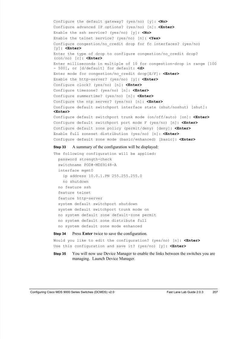
8/18/2019 FL_DCMDS_2.0.3_LG(1).pdf
http://slidepdf.com/reader/full/fldcmds203lg1pdf 207/482

8/18/2019 FL_DCMDS_2.0.3_LG(1).pdf
http://slidepdf.com/reader/full/fldcmds203lg1pdf 208/482
208 Configuring Cisco MDS 9000 Series Switches (DCMDS) v2.0 © 2014 Fast Lane and Cisco Systems, Inc.
Step 36 Connect to your 9148, enter the password 1234QWer, then click Open.
Step 37 Note all ports are (shut)down.
Step 38 Enable interfaces FC1/1 and FC1/2 on the 9148s as an F port and
FC1/11 and FC1/12 as an E port. Since all ports are autosensing by default,
enabling them is enough.
Note The 9222i has been preconfigured.
Step 39 Launch DCNM SAN, enter the password 1234QWer, click Login.
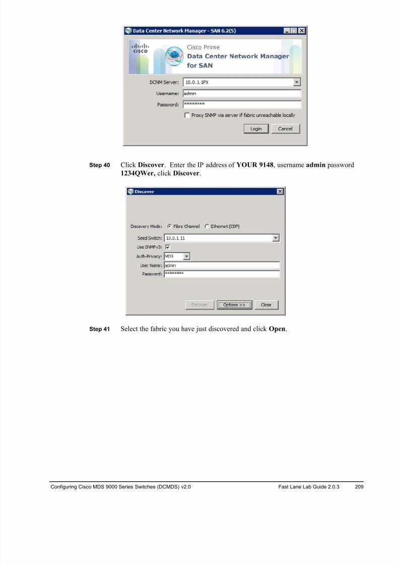
8/18/2019 FL_DCMDS_2.0.3_LG(1).pdf
http://slidepdf.com/reader/full/fldcmds203lg1pdf 209/482
Configuring Cisco MDS 9000 Series Switches (DCMDS) v2.0 Fast Lane Lab Guide 2.0.3 209
Step 40 Click Discover. Enter the IP address of YOUR 9148, username admin password
1234QWer, click Discover.
Step 41 Select the fabric you have just discovered and click Open.

8/18/2019 FL_DCMDS_2.0.3_LG(1).pdf
http://slidepdf.com/reader/full/fldcmds203lg1pdf 210/482
210 Configuring Cisco MDS 9000 Series Switches (DCMDS) v2.0 © 2014 Fast Lane and Cisco Systems, Inc.
Step 42 In the DCNM SAN toolbar, click the Create VSAN icon.
Step 43 Enter the VSAN ID to be created.
ONLY POD#-MDS9148-A and MDS9222i-A: enter VSAN ID P1
ONLY POD#-MDS9148-B and MDS9222i-B: enter VSAN ID P2
Step 44 Click Create.
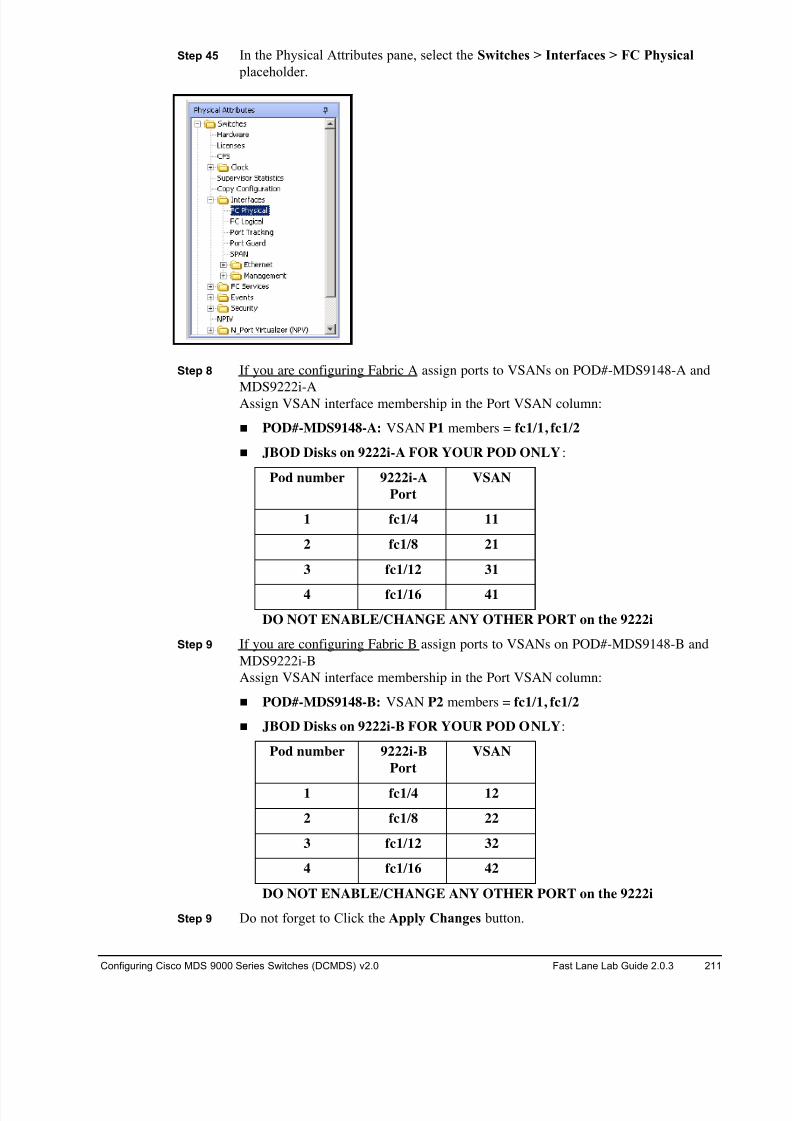
8/18/2019 FL_DCMDS_2.0.3_LG(1).pdf
http://slidepdf.com/reader/full/fldcmds203lg1pdf 211/482
Configuring Cisco MDS 9000 Series Switches (DCMDS) v2.0 Fast Lane Lab Guide 2.0.3 211
Step 45 In the Physical Attributes pane, select the Switches > Interfaces > FC Physical
placeholder.
Step 8 If you are configuring Fabric A assign ports to VSANs on POD#-MDS9148-A and
MDS9222i-AAssign VSAN interface membership in the Port VSAN column:
! POD#-MDS9148-A: VSAN P1 members = fc1/1, fc1/2
! JBOD Disks on 9222i-A FOR YOUR POD ONLY:
Pod number 9222i-A
Port
VSAN
1 fc1/4 11
2 fc1/8 21
3 fc1/12 31
4 fc1/16 41
DO NOT ENABLE/CHANGE ANY OTHER PORT on the 9222i
Step 9 If you are configuring Fabric B assign ports to VSANs on POD#-MDS9148-B and
MDS9222i-B
Assign VSAN interface membership in the Port VSAN column:
! POD#-MDS9148-B: VSAN P2 members = fc1/1, fc1/2
! JBOD Disks on 9222i-B FOR YOUR POD ONLY:
Pod number 9222i-B
Port
VSAN
1 fc1/4 12
2 fc1/8 22
3 fc1/12 32
4 fc1/16 42
DO NOT ENABLE/CHANGE ANY OTHER PORT on the 9222i
Step 9 Do not forget to Click the Apply Changes button.
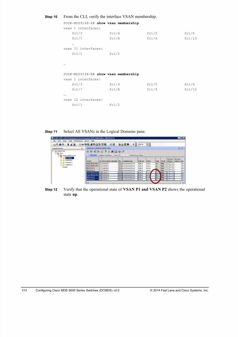
8/18/2019 FL_DCMDS_2.0.3_LG(1).pdf
http://slidepdf.com/reader/full/fldcmds203lg1pdf 212/482
212 Configuring Cisco MDS 9000 Series Switches (DCMDS) v2.0 © 2014 Fast Lane and Cisco Systems, Inc.
Step 10 From the CLI, verify the interface VSAN membership.
POD#-MDS9148-A# show vsan membership
vsan 1 interfaces:
fc1/3 fc1/4 fc1/5 fc1/6
fc1/7 fc1/8 fc1/9 fc1/10
…
vsan 11 interfaces:
fc1/1 fc1/2
…
POD#-MDS9148-B# show vsan membership
vsan 1 interfaces:
fc1/3 fc1/4 fc1/5 fc1/6
fc1/7 fc1/8 fc1/9 fc1/10
…
vsan 12 interfaces:
fc1/1 fc1/2
Step 11 Select All VSANs in the Logical Domains pane.
Step 12 Verify that the operational state of VSAN P1 and VSAN P2 shows the operational
state up.
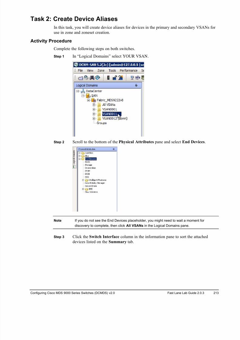
8/18/2019 FL_DCMDS_2.0.3_LG(1).pdf
http://slidepdf.com/reader/full/fldcmds203lg1pdf 213/482
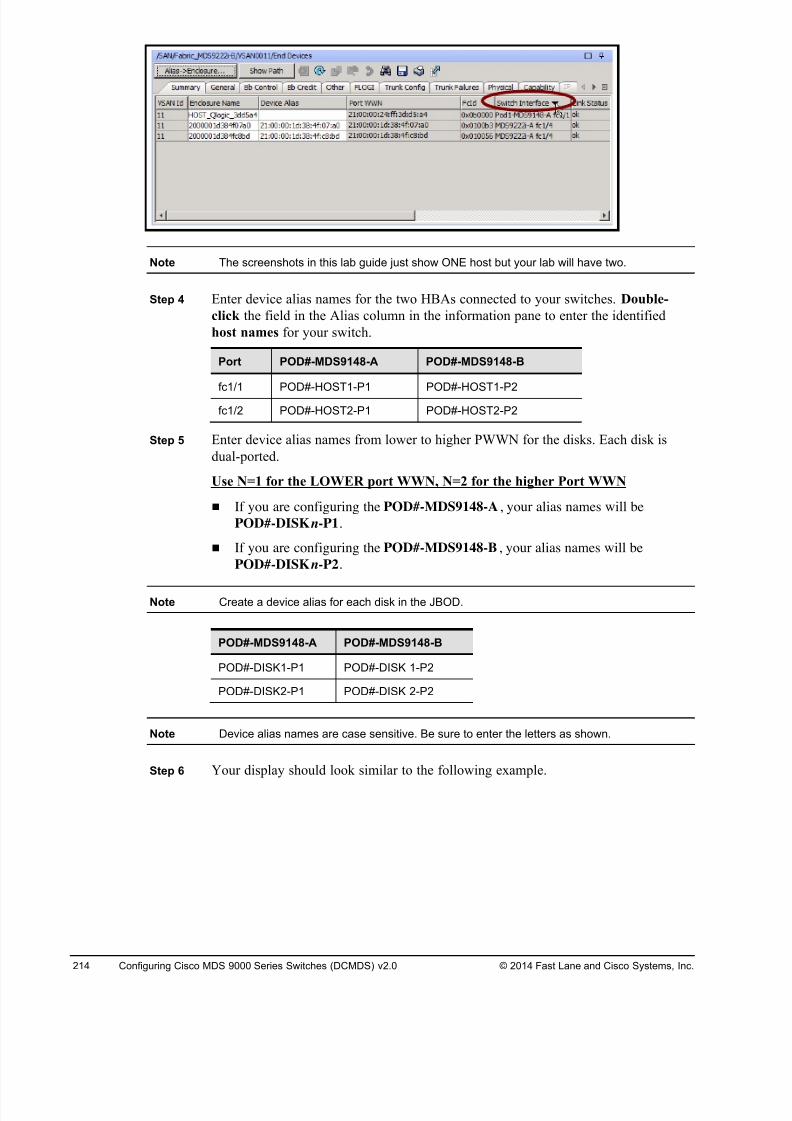
8/18/2019 FL_DCMDS_2.0.3_LG(1).pdf
http://slidepdf.com/reader/full/fldcmds203lg1pdf 214/482
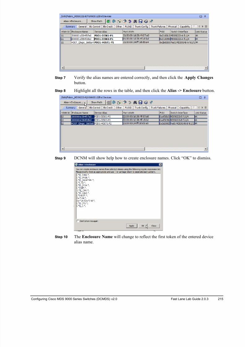
8/18/2019 FL_DCMDS_2.0.3_LG(1).pdf
http://slidepdf.com/reader/full/fldcmds203lg1pdf 215/482
Configuring Cisco MDS 9000 Series Switches (DCMDS) v2.0 Fast Lane Lab Guide 2.0.3 215
Step 7 Verify the alias names are entered correctly, and then click the Apply Changes
button.
Step 8 Highlight all the rows in the table, and then click the Alias -> Enclosure button.
Step 9 DCNM will show help how to create enclosure names. Click “OK” to dismiss.
Step 10 The Enclosure Name will change to reflect the first token of the entered device
alias name.
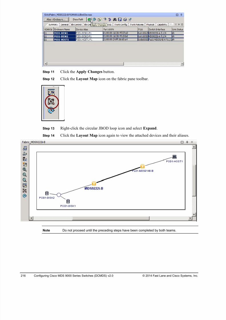
8/18/2019 FL_DCMDS_2.0.3_LG(1).pdf
http://slidepdf.com/reader/full/fldcmds203lg1pdf 216/482
216 Configuring Cisco MDS 9000 Series Switches (DCMDS) v2.0 © 2014 Fast Lane and Cisco Systems, Inc.
Step 11 Click the Apply Changes button.
Step 12 Click the Layout Map icon on the fabric pane toolbar.
Step 13 Right-click the circular JBOD loop icon and select Expand.
Step 14 Click the Layout Map icon again to view the attached devices and their aliases.
Note Do not proceed until the preceding steps have been completed by both teams.
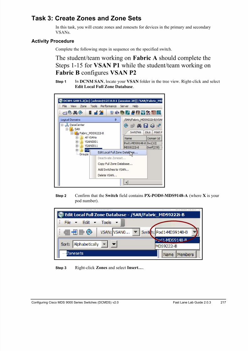
8/18/2019 FL_DCMDS_2.0.3_LG(1).pdf
http://slidepdf.com/reader/full/fldcmds203lg1pdf 217/482
Configuring Cisco MDS 9000 Series Switches (DCMDS) v2.0 Fast Lane Lab Guide 2.0.3 217
Task 3: Create Zones and Zone Sets
In this task, you will create zones and zonesets for devices in the primary and secondary
VSANs.
Activity Procedure
Complete the following steps in sequence on the specified switch.
The student/team working on Fabric A should complete the
Steps 1-15 for VSAN P1 while the student/team working on
Fabric B configures VSAN P2
Step 1 In DCNM SAN, locate your VSAN folder in the tree view. Right-click and select
Edit Local Full Zone Database.
Step 2 Confirm that the Switch field contains PX-POD#-MDS9148-A (where X is your
pod number).
Step 3 Right-click Zones and select Insert….
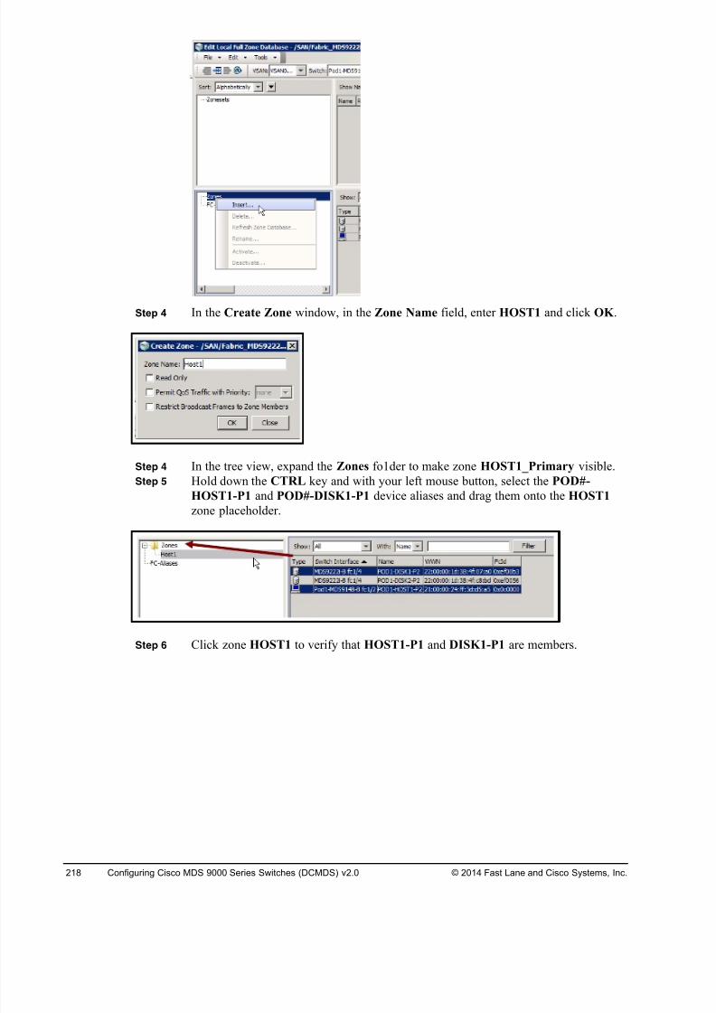
8/18/2019 FL_DCMDS_2.0.3_LG(1).pdf
http://slidepdf.com/reader/full/fldcmds203lg1pdf 218/482
218 Configuring Cisco MDS 9000 Series Switches (DCMDS) v2.0 © 2014 Fast Lane and Cisco Systems, Inc.
Step 4 In the Create Zone window, in the Zone Name field, enter HOST1 and click OK .
Step 4 In the tree view, expand the Zones fo1der to make zone HOST1_Primary visible.
Step 5 Hold down the CTRL key and with your left mouse button, select the POD#-
HOST1-P1 and POD#-DISK1-P1 device aliases and drag them onto the HOST1
zone placeholder.
Step 6 Click zone HOST1 to verify that HOST1-P1 and DISK1-P1 are members.
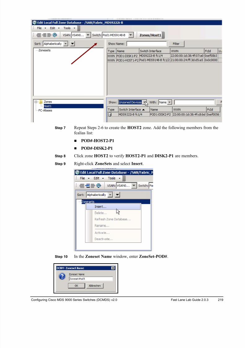
8/18/2019 FL_DCMDS_2.0.3_LG(1).pdf
http://slidepdf.com/reader/full/fldcmds203lg1pdf 219/482
Configuring Cisco MDS 9000 Series Switches (DCMDS) v2.0 Fast Lane Lab Guide 2.0.3 219
Step 7 Repeat Steps 2-6 to create the HOST2 zone. Add the following members from the
fcalias list:
! POD#-HOST2-P1
! POD#-DISK2-P1
Step 8 Click zone HOST2 to verify HOST2-P1 and DISK2-P1 are members.
Step 9 Right-click ZoneSets and select Insert.
Step 10 In the Zoneset Name window, enter ZoneSet-POD#.
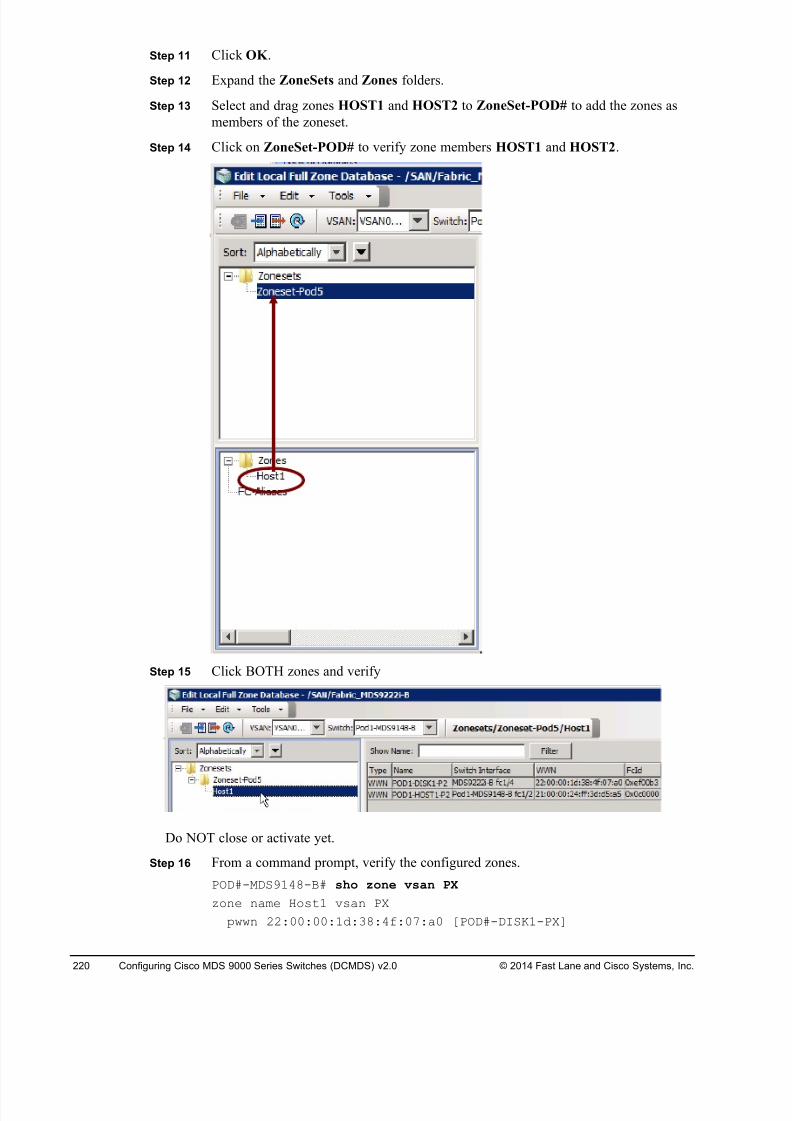
8/18/2019 FL_DCMDS_2.0.3_LG(1).pdf
http://slidepdf.com/reader/full/fldcmds203lg1pdf 220/482
220 Configuring Cisco MDS 9000 Series Switches (DCMDS) v2.0 © 2014 Fast Lane and Cisco Systems, Inc.
Step 11 Click OK .
Step 12 Expand the ZoneSets and Zones folders.
Step 13 Select and drag zones HOST1 and HOST2 to ZoneSet-POD# to add the zones as
members of the zoneset.
Step 14 Click on ZoneSet-POD# to verify zone members HOST1 and HOST2.
Step 15 Click BOTH zones and verify
Do NOT close or activate yet.
Step 16 From a command prompt, verify the configured zones.
POD#-MDS9148-B# sho zone vsan PX
zone name Host1 vsan PX
pwwn 22:00:00:1d:38:4f:07:a0 [POD#-DISK1-PX]
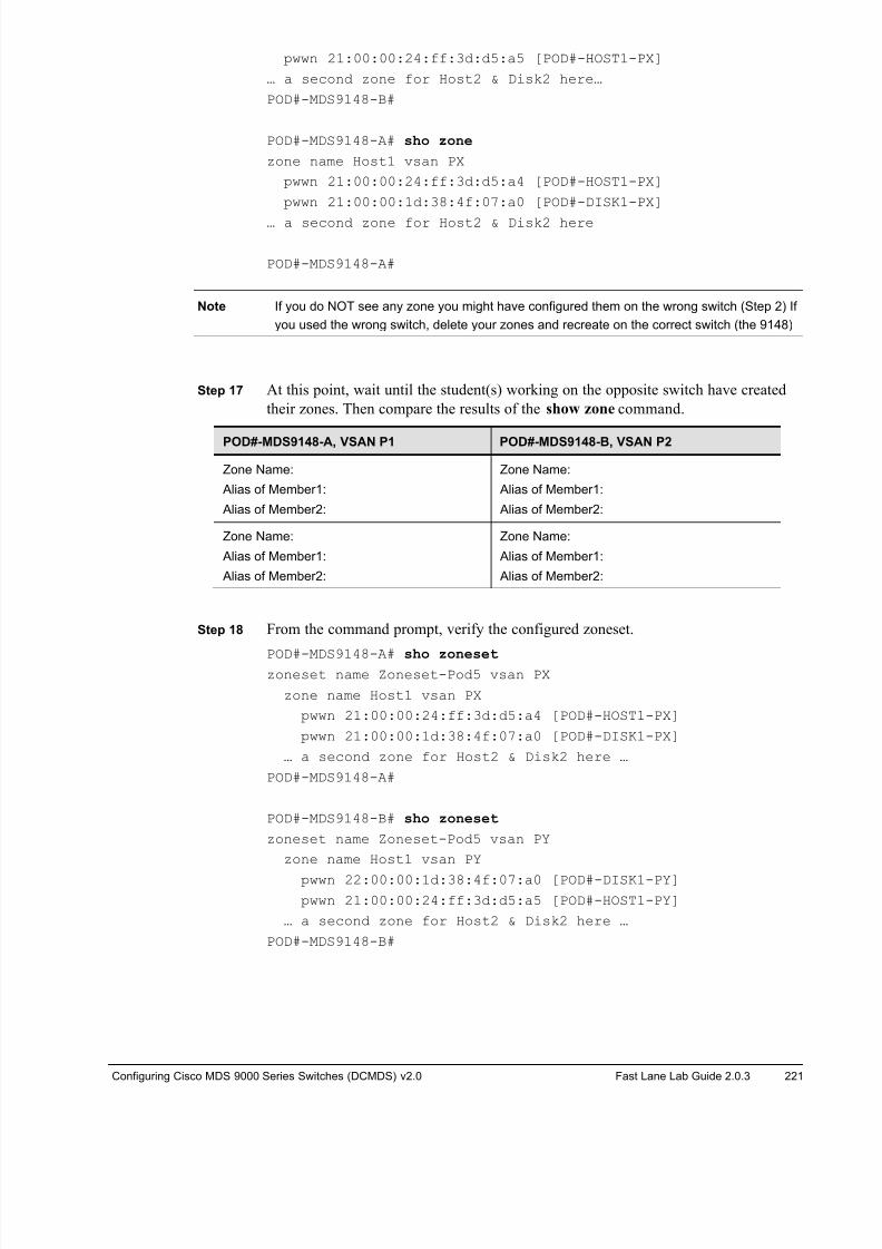
8/18/2019 FL_DCMDS_2.0.3_LG(1).pdf
http://slidepdf.com/reader/full/fldcmds203lg1pdf 221/482
Configuring Cisco MDS 9000 Series Switches (DCMDS) v2.0 Fast Lane Lab Guide 2.0.3 221
pwwn 21:00:00:24:ff:3d:d5:a5 [POD#-HOST1-PX]
… a second zone for Host2 & Disk2 here…
POD#-MDS9148-B#
POD#-MDS9148-A# sho zone
zone name Host1 vsan PX
pwwn 21:00:00:24:ff:3d:d5:a4 [POD#-HOST1-PX]
pwwn 21:00:00:1d:38:4f:07:a0 [POD#-DISK1-PX]
… a second zone for Host2 & Disk2 here
POD#-MDS9148-A#
Note If you do NOT see any zone you might have configured them on the wrong switch (Step 2) If
you used the wrong switch, delete your zones and recreate on the correct switch (the 9148)
Step 17 At this point, wait until the student(s) working on the opposite switch have created
their zones. Then compare the results of the show zone command.
POD#-MDS9148-A, VSAN P1 POD#-MDS9148-B, VSAN P2
Zone Name:
Alias of Member1:
Alias of Member2:
Zone Name:
Alias of Member1:
Alias of Member2:
Zone Name:
Alias of Member1:
Alias of Member2:
Zone Name:
Alias of Member1:
Alias of Member2:
Step 18 From the command prompt, verify the configured zoneset.
POD#-MDS9148-A# sho zoneset zoneset name Zoneset-Pod5 vsan PX
zone name Host1 vsan PX
pwwn 21:00:00:24:ff:3d:d5:a4 [POD#-HOST1-PX]
pwwn 21:00:00:1d:38:4f:07:a0 [POD#-DISK1-PX]
… a second zone for Host2 & Disk2 here …
POD#-MDS9148-A#
POD#-MDS9148-B# sho zoneset
zoneset name Zoneset-Pod5 vsan PY
zone name Host1 vsan PY
pwwn 22:00:00:1d:38:4f:07:a0 [POD#-DISK1-PY]
pwwn 21:00:00:24:ff:3d:d5:a5 [POD#-HOST1-PY]
… a second zone for Host2 & Disk2 here …
POD#-MDS9148-B#
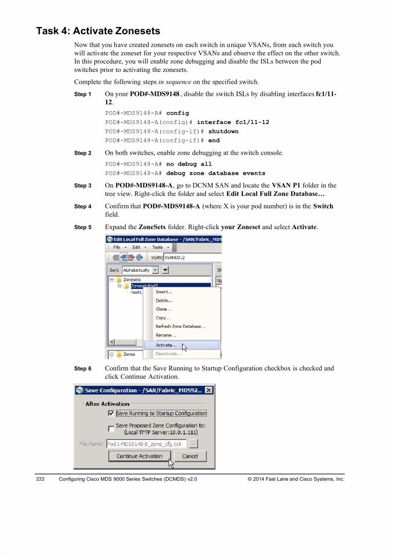
8/18/2019 FL_DCMDS_2.0.3_LG(1).pdf
http://slidepdf.com/reader/full/fldcmds203lg1pdf 222/482
222 Configuring Cisco MDS 9000 Series Switches (DCMDS) v2.0 © 2014 Fast Lane and Cisco Systems, Inc.
Task 4: Activate Zonesets
Now that you have created zonesets on each switch in unique VSANs, from each switch you
will activate the zoneset for your respective VSANs and observe the effect on the other switch.
In this procedure, you will enable zone debugging and disable the ISLs between the pod
switches prior to activating the zonesets.
Complete the following steps in sequence on the specified switch.
Step 1On your POD#-MDS9148 , disable the switch ISLs by disabling interfaces fc1/11-12.
POD#-MDS9148-A# config
POD#-MDS9148-A(config)# interface fc1/11-12
POD#-MDS9148-A(config-if)# shutdown
POD#-MDS9148-A(config-if)# end
Step 2 On both switches, enable zone debugging at the switch console.
POD#-MDS9148-A# no debug all
POD#-MDS9148-A# debug zone database events
Step 3 On POD#-MDS9148-A, go to DCNM SAN and locate the VSAN P1 folder in the
tree view. Right-click the folder and select Edit Local Full Zone Database…
Step 4 Confirm that POD#-MDS9148-A (where X is your pod number) is in the Switch
field.
Step 5 Expand the ZoneSets folder. Right-click your Zoneset and select Activate.
Step 6 Confirm that the Save Running to Startup Configuration checkbox is checked and
click Continue Activation.
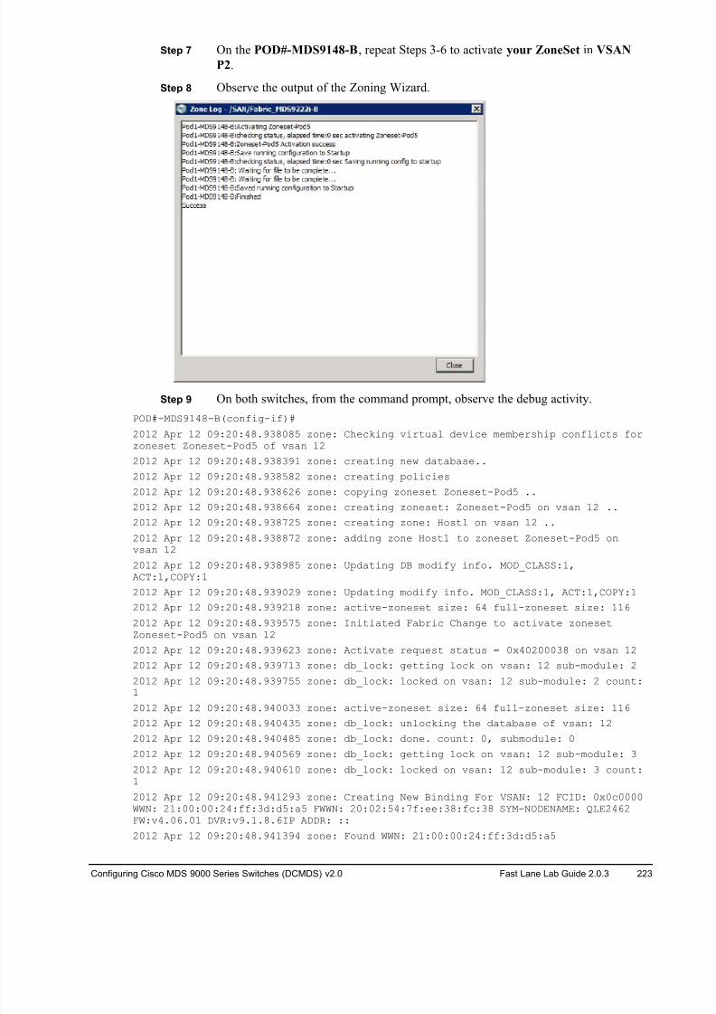
8/18/2019 FL_DCMDS_2.0.3_LG(1).pdf
http://slidepdf.com/reader/full/fldcmds203lg1pdf 223/482
Configuring Cisco MDS 9000 Series Switches (DCMDS) v2.0 Fast Lane Lab Guide 2.0.3 223
Step 7 On the POD#-MDS9148-B, repeat Steps 3-6 to activate your ZoneSet in VSAN
P2.
Step 8 Observe the output of the Zoning Wizard.
Step 9 On both switches, from the command prompt, observe the debug activity.
POD#-MDS9148-B(config-if)#
2012 Apr 12 09:20:48.938085 zone: Checking virtual device membership conflicts forzoneset Zoneset-Pod5 of vsan 12
2012 Apr 12 09:20:48.938391 zone: creating new database..
2012 Apr 12 09:20:48.938582 zone: creating policies
2012 Apr 12 09:20:48.938626 zone: copying zoneset Zoneset-Pod5 ..
2012 Apr 12 09:20:48.938664 zone: creating zoneset: Zoneset-Pod5 on vsan 12 ..
2012 Apr 12 09:20:48.938725 zone: creating zone: Host1 on vsan 12 ..
2012 Apr 12 09:20:48.938872 zone: adding zone Host1 to zoneset Zoneset-Pod5 onvsan 12
2012 Apr 12 09:20:48.938985 zone: Updating DB modify info. MOD_CLASS:1,ACT:1,COPY:1
2012 Apr 12 09:20:48.939029 zone: Updating modify info. MOD_CLASS:1, ACT:1,COPY:1
2012 Apr 12 09:20:48.939218 zone: active-zoneset size: 64 full-zoneset size: 116
2012 Apr 12 09:20:48.939575 zone: Initiated Fabric Change to activate zonesetZoneset-Pod5 on vsan 12
2012 Apr 12 09:20:48.939623 zone: Activate request status = 0x40200038 on vsan 12
2012 Apr 12 09:20:48.939713 zone: db_lock: getting lock on vsan: 12 sub-module: 2
2012 Apr 12 09:20:48.939755 zone: db_lock: locked on vsan: 12 sub-module: 2 count:1
2012 Apr 12 09:20:48.940033 zone: active-zoneset size: 64 full-zoneset size: 1162012 Apr 12 09:20:48.940435 zone: db_lock: unlocking the database of vsan: 12
2012 Apr 12 09:20:48.940485 zone: db_lock: done. count: 0, submodule: 0
2012 Apr 12 09:20:48.940569 zone: db_lock: getting lock on vsan: 12 sub-module: 3
2012 Apr 12 09:20:48.940610 zone: db_lock: locked on vsan: 12 sub-module: 3 count:1
2012 Apr 12 09:20:48.941293 zone: Creating New Binding For VSAN: 12 FCID: 0x0c0000WWN: 21:00:00:24:ff:3d:d5:a5 FWWN: 20:02:54:7f:ee:38:fc:38 SYM-NODENAME: QLE2462FW:v4.06.01 DVR:v9.1.8.6IP ADDR: ::
2012 Apr 12 09:20:48.941394 zone: Found WWN: 21:00:00:24:ff:3d:d5:a5
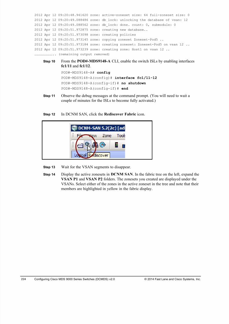
8/18/2019 FL_DCMDS_2.0.3_LG(1).pdf
http://slidepdf.com/reader/full/fldcmds203lg1pdf 224/482
224 Configuring Cisco MDS 9000 Series Switches (DCMDS) v2.0 © 2014 Fast Lane and Cisco Systems, Inc.
2012 Apr 12 09:20:48.941620 zone: active-zoneset size: 64 full-zoneset size: 0
2012 Apr 12 09:20:49.088486 zone: db_lock: unlocking the database of vsan: 12
2012 Apr 12 09:20:49.088562 zone: db_lock: done. count: 0, submodule: 0
2012 Apr 12 09:20:51.972875 zone: creating new database..
2012 Apr 12 09:20:51.973098 zone: creating policies
2012 Apr 12 09:20:51.973145 zone: copying zoneset Zoneset-Pod5 ..
2012 Apr 12 09:20:51.973184 zone: creating zoneset: Zoneset-Pod5 on vsan 12 ..
2012 Apr 12 09:20:51.973239 zone: creating zone: Host1 on vsan 12 ..
……………………….. (remaining output removed)
Step 10 From the POD#-MDS9148-A CLI, enable the switch ISLs by enabling interfaces
fc1/11 and fc1/12.
POD#-MDS9148-A# config
POD#-MDS9148-A(config)# interface fc1/11-12
POD#-MDS9148-A(config-if)# no shutdown
POD#-MDS9148-A(config-if)# end
Step 11 Observe the debug messages at the command prompt. (You will need to wait a
couple of minutes for the ISLs to become fully activated.)
Step 12 In DCNM SAN, click the Rediscover Fabric icon.
Step 13 Wait for the VSAN segments to disappear.
Step 14 Display the active zonesets in DCNM SAN. In the fabric tree on the left, expand the
VSAN P1 and VSAN P2 folders. The zonesets you created are displayed under the
VSANs. Select either of the zones in the active zoneset in the tree and note that their
members are highlighted in yellow in the fabric display.
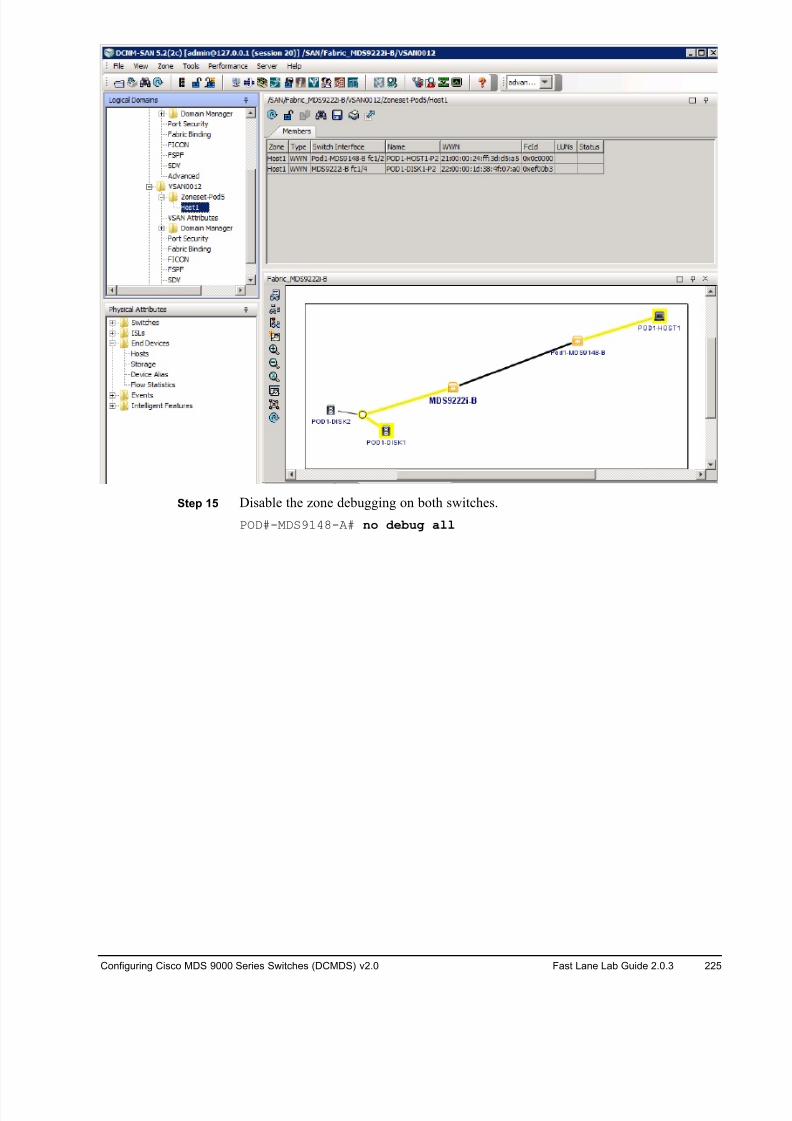
8/18/2019 FL_DCMDS_2.0.3_LG(1).pdf
http://slidepdf.com/reader/full/fldcmds203lg1pdf 225/482
Configuring Cisco MDS 9000 Series Switches (DCMDS) v2.0 Fast Lane Lab Guide 2.0.3 225
Step 15 Disable the zone debugging on both switches.
POD#-MDS9148-A# no debug all
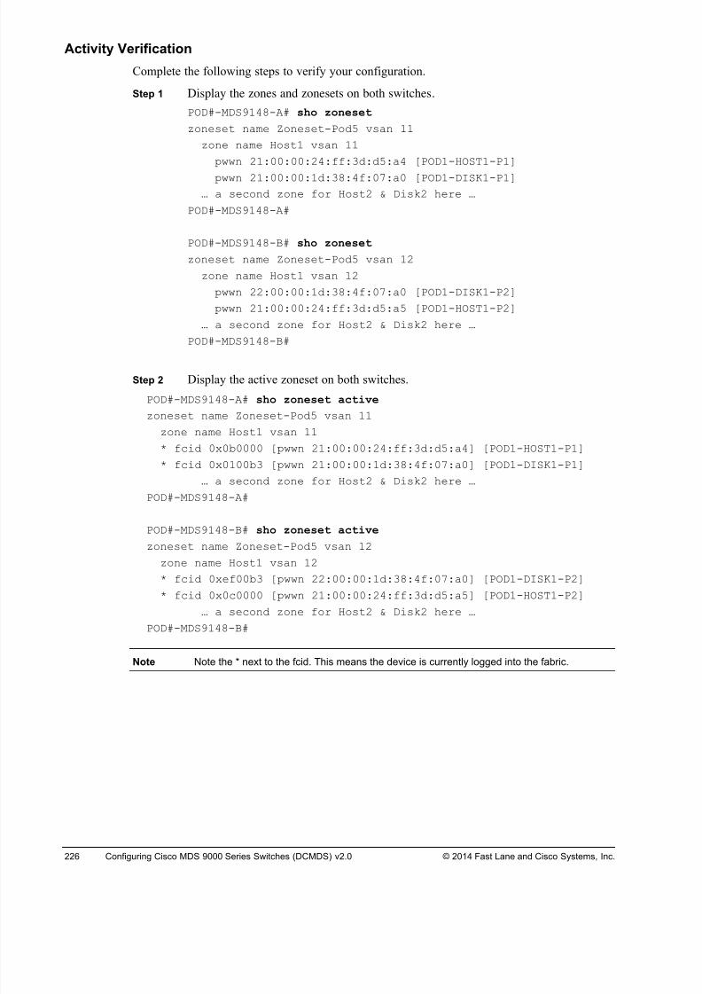
8/18/2019 FL_DCMDS_2.0.3_LG(1).pdf
http://slidepdf.com/reader/full/fldcmds203lg1pdf 226/482
226 Configuring Cisco MDS 9000 Series Switches (DCMDS) v2.0 © 2014 Fast Lane and Cisco Systems, Inc.
Activity Verification
Complete the following steps to verify your configuration.
Step 1 Display the zones and zonesets on both switches.
POD#-MDS9148-A# sho zoneset
zoneset name Zoneset-Pod5 vsan 11
zone name Host1 vsan 11
pwwn 21:00:00:24:ff:3d:d5:a4 [POD1-HOST1-P1]
pwwn 21:00:00:1d:38:4f:07:a0 [POD1-DISK1-P1]
… a second zone for Host2 & Disk2 here …
POD#-MDS9148-A#
POD#-MDS9148-B# sho zoneset
zoneset name Zoneset-Pod5 vsan 12
zone name Host1 vsan 12
pwwn 22:00:00:1d:38:4f:07:a0 [POD1-DISK1-P2]
pwwn 21:00:00:24:ff:3d:d5:a5 [POD1-HOST1-P2]
… a second zone for Host2 & Disk2 here …
POD#-MDS9148-B#
Step 2 Display the active zoneset on both switches.
POD#-MDS9148-A# sho zoneset active
zoneset name Zoneset-Pod5 vsan 11
zone name Host1 vsan 11
* fcid 0x0b0000 [pwwn 21:00:00:24:ff:3d:d5:a4] [POD1-HOST1-P1]
* fcid 0x0100b3 [pwwn 21:00:00:1d:38:4f:07:a0] [POD1-DISK1-P1]
… a second zone for Host2 & Disk2 here …
POD#-MDS9148-A#
POD#-MDS9148-B# sho zoneset active
zoneset name Zoneset-Pod5 vsan 12
zone name Host1 vsan 12
* fcid 0xef00b3 [pwwn 22:00:00:1d:38:4f:07:a0] [POD1-DISK1-P2]
* fcid 0x0c0000 [pwwn 21:00:00:24:ff:3d:d5:a5] [POD1-HOST1-P2]
… a second zone for Host2 & Disk2 here …
POD#-MDS9148-B#
Note Note the * next to the fcid. This means the device is currently logged into the fabric.
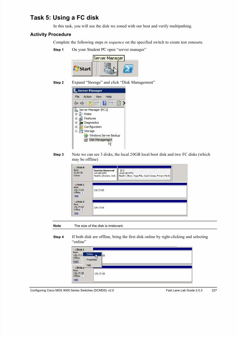
8/18/2019 FL_DCMDS_2.0.3_LG(1).pdf
http://slidepdf.com/reader/full/fldcmds203lg1pdf 227/482
Configuring Cisco MDS 9000 Series Switches (DCMDS) v2.0 Fast Lane Lab Guide 2.0.3 227
Task 5: Using a FC disk
In this task, you will use the disk we zoned with our host and verify multipathing.
Activity Procedure
Complete the following steps in sequence on the specified switch to create test zonesets.
Step 1 On your Student PC open “server manager”
Step 2 Expand “Storage” and click “Disk Management”
Step 3 Note we can see 3 disks, the local 20GB local boot disk and two FC disks (which
may be offline)
Note The size of the disk is irrelevant.
Step 4 If both disk are offline, bring the first disk online by right-clicking and selecting“online”
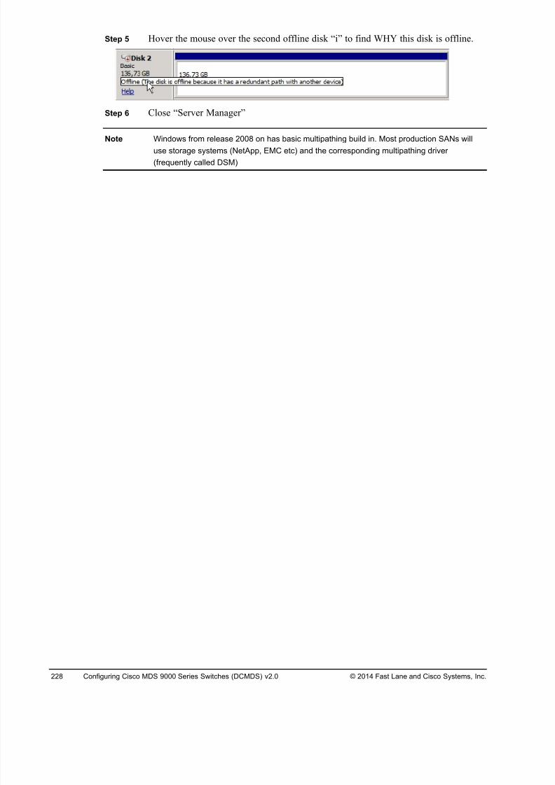
8/18/2019 FL_DCMDS_2.0.3_LG(1).pdf
http://slidepdf.com/reader/full/fldcmds203lg1pdf 228/482
228 Configuring Cisco MDS 9000 Series Switches (DCMDS) v2.0 © 2014 Fast Lane and Cisco Systems, Inc.
Step 5 Hover the mouse over the second offline disk “i” to find WHY this disk is offline.
Step 6 Close “Server Manager”
Note Windows from release 2008 on has basic multipathing build in. Most production SANs will
use storage systems (NetApp, EMC etc) and the corresponding multipathing driver
(frequently called DSM)
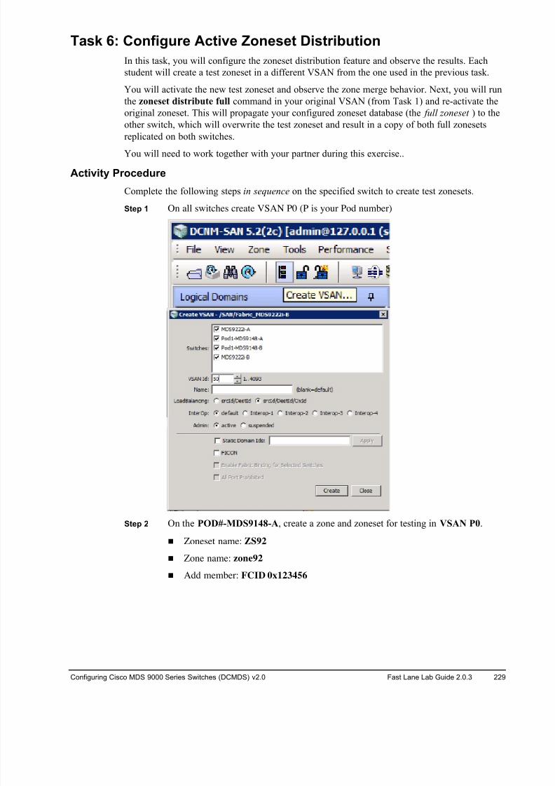
8/18/2019 FL_DCMDS_2.0.3_LG(1).pdf
http://slidepdf.com/reader/full/fldcmds203lg1pdf 229/482
Configuring Cisco MDS 9000 Series Switches (DCMDS) v2.0 Fast Lane Lab Guide 2.0.3 229
Task 6: Configure Active Zoneset Distribution
In this task, you will configure the zoneset distribution feature and observe the results. Each
student will create a test zoneset in a different VSAN from the one used in the previous task.
You will activate the new test zoneset and observe the zone merge behavior. Next, you will run
the zoneset distribute full command in your original VSAN (from Task 1) and re-activate the
original zoneset. This will propagate your configured zoneset database (the full zoneset ) to the
other switch, which will overwrite the test zoneset and result in a copy of both full zonesets
replicated on both switches.
You will need to work together with your partner during this exercise..
Activity Procedure
Complete the following steps in sequence on the specified switch to create test zonesets.
Step 1 On all switches create VSAN P0 (P is your Pod number)
Step 2 On the POD#-MDS9148-A, create a zone and zoneset for testing in VSAN P0.
! Zoneset name: ZS92
! Zone name: zone92
! Add member: FCID 0x123456
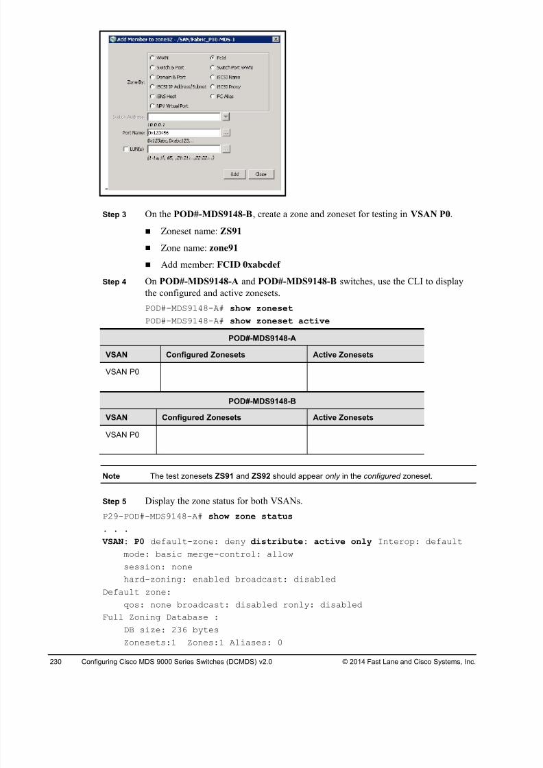
8/18/2019 FL_DCMDS_2.0.3_LG(1).pdf
http://slidepdf.com/reader/full/fldcmds203lg1pdf 230/482
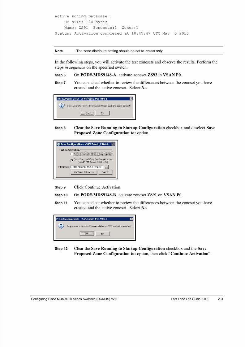
8/18/2019 FL_DCMDS_2.0.3_LG(1).pdf
http://slidepdf.com/reader/full/fldcmds203lg1pdf 231/482
Configuring Cisco MDS 9000 Series Switches (DCMDS) v2.0 Fast Lane Lab Guide 2.0.3 231
Active Zoning Database :
DB size: 124 bytes
Name: ZS91 Zonesets:1 Zones:1
Status: Activation completed at 18:45:47 UTC Mar 5 2010
Note The zone distribute setting should be set to active only .
In the following steps, you will activate the test zonesets and observe the results. Perform thesteps in sequence on the specified switch.
Step 6 On POD#-MDS9148-A, activate zoneset ZS92 in VSAN P0.
Step 7 You can select whether to review the differences between the zoneset you have
created and the active zoneset. Select No.
Step 8 Clear the Save Running to Startup Configuration checkbox and deselect Save
Proposed Zone Configuration to: option.
Step 9 Click Continue Activation.
Step 10 On POD#-MDS9148-B, activate zoneset ZS91 on VSAN P0.
Step 11 You can select whether to review the differences between the zoneset you have
created and the active zoneset. Select No.
Step 12 Clear the Save Running to Startup Configuration checkbox and the Save
Proposed Zone Configuration to: option, then click “Continue Activation”.
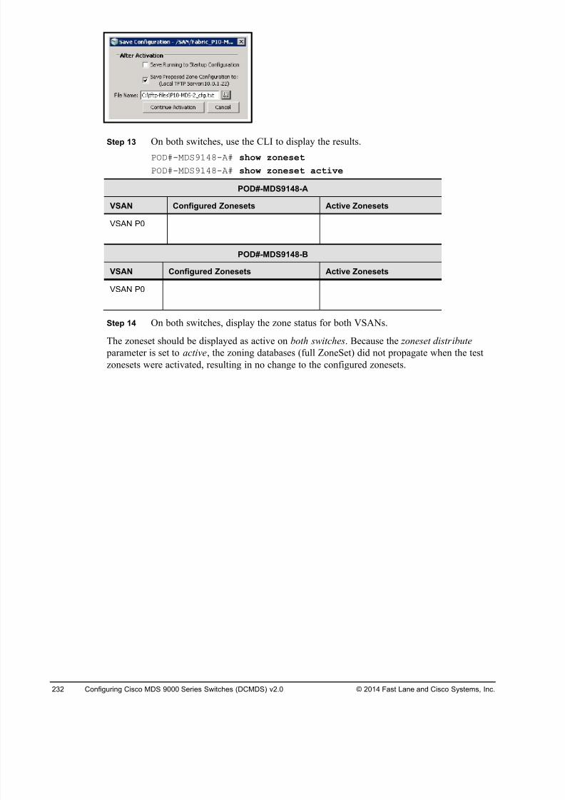
8/18/2019 FL_DCMDS_2.0.3_LG(1).pdf
http://slidepdf.com/reader/full/fldcmds203lg1pdf 232/482
232 Configuring Cisco MDS 9000 Series Switches (DCMDS) v2.0 © 2014 Fast Lane and Cisco Systems, Inc.
Step 13 On both switches, use the CLI to display the results.
POD#-MDS9148-A# show zoneset
POD#-MDS9148-A# show zoneset active
POD#-MDS9148-A
VSAN Configured Zonesets Active Zonesets
VSAN P0
POD#-MDS9148-B
VSAN Configured Zonesets Active Zonesets
VSAN P0
Step 14 On both switches, display the zone status for both VSANs.
The zoneset should be displayed as active on both switches. Because the zoneset distribute
parameter is set to active, the zoning databases (full ZoneSet) did not propagate when the test
zonesets were activated, resulting in no change to the configured zonesets.
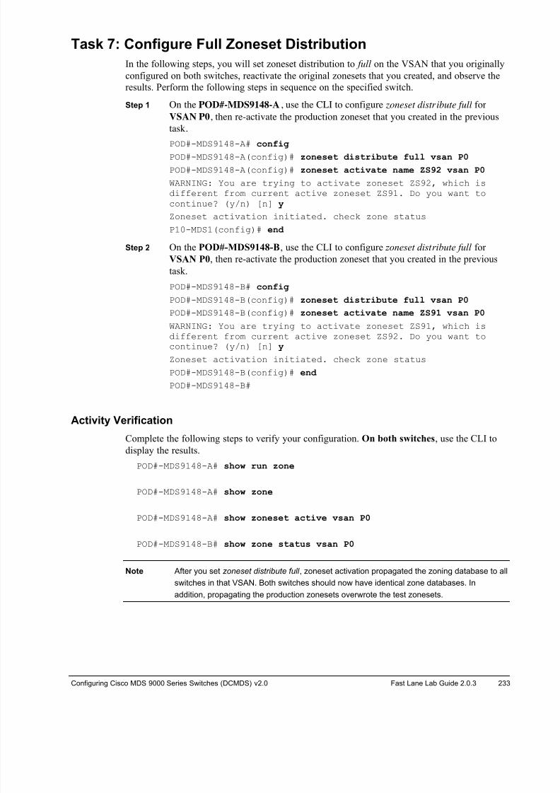
8/18/2019 FL_DCMDS_2.0.3_LG(1).pdf
http://slidepdf.com/reader/full/fldcmds203lg1pdf 233/482
Configuring Cisco MDS 9000 Series Switches (DCMDS) v2.0 Fast Lane Lab Guide 2.0.3 233
Task 7: Configure Full Zoneset Distribution
In the following steps, you will set zoneset distribution to full on the VSAN that you originally
configured on both switches, reactivate the original zonesets that you created, and observe the
results. Perform the following steps in sequence on the specified switch.
Step 1 On the POD#-MDS9148-A , use the CLI to configure zoneset distribute full for
VSAN P0, then re-activate the production zoneset that you created in the previous
task.
POD#-MDS9148-A# config
POD#-MDS9148-A(config)# zoneset distribute full vsan P0
POD#-MDS9148-A(config)# zoneset activate name ZS92 vsan P0
WARNING: You are trying to activate zoneset ZS92, which isdifferent from current active zoneset ZS91. Do you want tocontinue? (y/n) [n] y
Zoneset activation initiated. check zone status
P10-MDS1(config)# end
Step 2 On the POD#-MDS9148-B, use the CLI to configure zoneset distribute full for
VSAN P0, then re-activate the production zoneset that you created in the previous
task.
POD#-MDS9148-B# config
POD#-MDS9148-B(config)# zoneset distribute full vsan P0
POD#-MDS9148-B(config)# zoneset activate name ZS91 vsan P0
WARNING: You are trying to activate zoneset ZS91, which isdifferent from current active zoneset ZS92. Do you want tocontinue? (y/n) [n] y
Zoneset activation initiated. check zone status
POD#-MDS9148-B(config)# end
POD#-MDS9148-B#
Activity Verification
Complete the following steps to verify your configuration. On both switches, use the CLI to
display the results.
POD#-MDS9148-A# show run zone
POD#-MDS9148-A# show zone
POD#-MDS9148-A# show zoneset active vsan P0
POD#-MDS9148-B# show zone status vsan P0
Note After you set zoneset distribute full , zoneset activation propagated the zoning database to all
switches in that VSAN. Both switches should now have identical zone databases. In
addition, propagating the production zonesets overwrote the test zonesets.
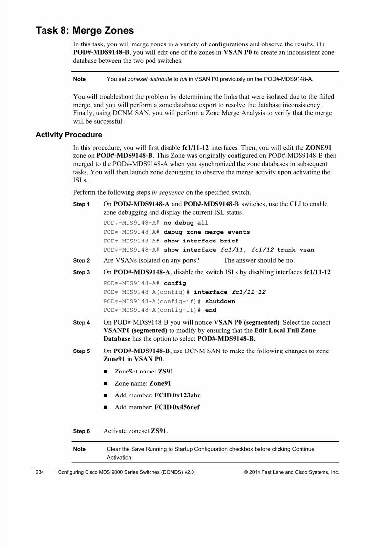
8/18/2019 FL_DCMDS_2.0.3_LG(1).pdf
http://slidepdf.com/reader/full/fldcmds203lg1pdf 234/482
234 Configuring Cisco MDS 9000 Series Switches (DCMDS) v2.0 © 2014 Fast Lane and Cisco Systems, Inc.
Task 8: Merge Zones
In this task, you will merge zones in a variety of configurations and observe the results. On
POD#-MDS9148-B, you will edit one of the zones in VSAN P0 to create an inconsistent zone
database between the two pod switches.
Note You set zoneset distribute to full in VSAN P0 previously on the POD#-MDS9148-A.
You will troubleshoot the problem by determining the links that were isolated due to the failedmerge, and you will perform a zone database export to resolve the database inconsistency.
Finally, using DCNM SAN, you will perform a Zone Merge Analysis to verify that the merge
will be successful.
Activity Procedure
In this procedure, you will first disable fc1/11-12 interfaces. Then, you will edit the ZONE91
zone on POD#-MDS9148-B. This Zone was originally configured on POD#-MDS9148-B then
merged to the POD#-MDS9148-A when you synchronized the zone databases in subsequent
tasks. You will then launch zone debugging to observe the merge activity upon activating the
ISLs.
Perform the following steps in sequence on the specified switch.
Step 1 On POD#-MDS9148-A and POD#-MDS9148-B switches, use the CLI to enable
zone debugging and display the current ISL status.
POD#-MDS9148-A# no debug all
POD#-MDS9148-A# debug zone merge events
POD#-MDS9148-A# show interface brief
POD#-MDS9148-A# show interface fc1/11, fc1/12 trunk vsan
Step 2 Are VSANs isolated on any ports? ______ The answer should be no.
Step 3 On POD#-MDS9148-A, disable the switch ISLs by disabling interfaces fc1/11-12
POD#-MDS9148-A# config
POD#-MDS9148-A(config)# interface fc1/11-12
POD#-MDS9148-A(config-if)# shutdown
POD#-MDS9148-A(config-if)# end
Step 4 On POD#-MDS9148-B you will notice VSAN P0 (segmented). Select the correct
VSANP0 (segmented) to modify by ensuring that the Edit Local Full Zone
Database has the option to select POD#-MDS9148-B.
Step 5 On POD#-MDS9148-B, use DCNM SAN to make the following changes to zone
Zone91 in VSAN P0.
! ZoneSet name: ZS91
! Zone name: Zone91
! Add member: FCID 0x123abc
! Add member: FCID 0x456def
Step 6 Activate zoneset ZS91.
Note Clear the Save Running to Startup Configuration checkbox before clicking Continue
Activation.
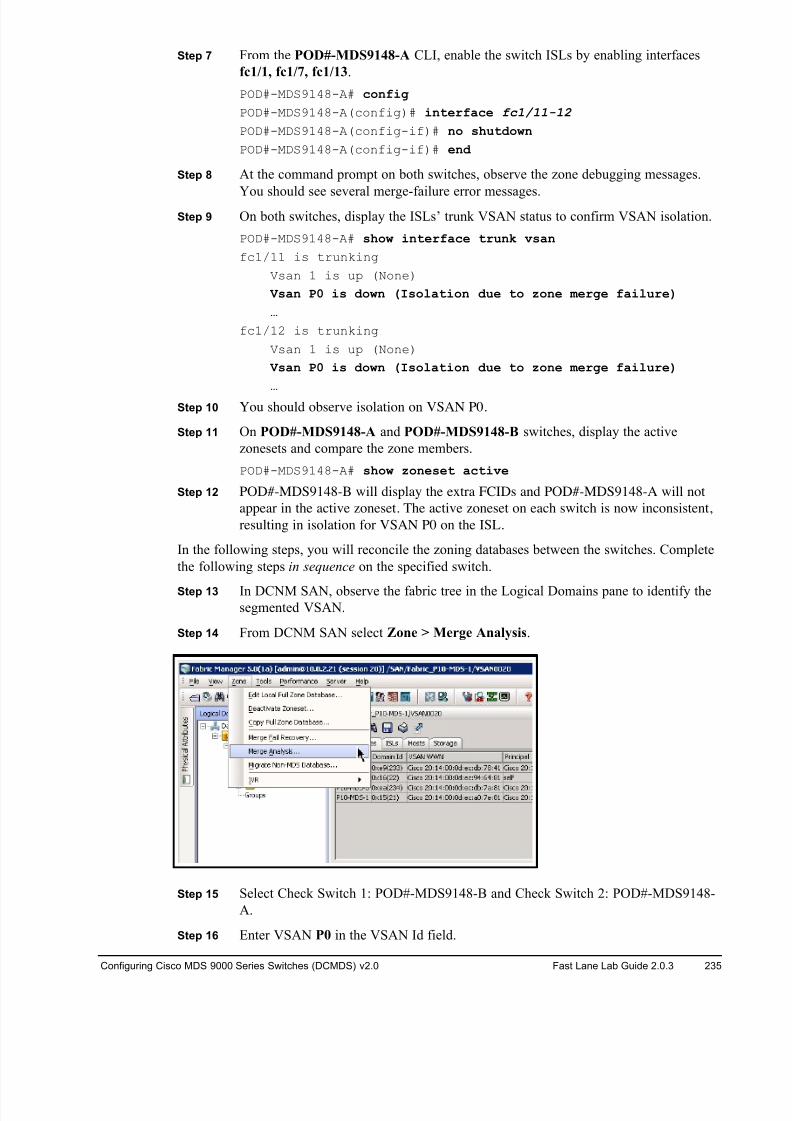
8/18/2019 FL_DCMDS_2.0.3_LG(1).pdf
http://slidepdf.com/reader/full/fldcmds203lg1pdf 235/482
Configuring Cisco MDS 9000 Series Switches (DCMDS) v2.0 Fast Lane Lab Guide 2.0.3 235
Step 7 From the POD#-MDS9148-A CLI, enable the switch ISLs by enabling interfaces
fc1/1, fc1/7, fc1/13.
POD#-MDS9148-A# config
POD#-MDS9148-A(config)# interface fc1/11-12
POD#-MDS9148-A(config-if)# no shutdown
POD#-MDS9148-A(config-if)# end
Step 8 At the command prompt on both switches, observe the zone debugging messages.
You should see several merge-failure error messages. Step 9 On both switches, display the ISLs’ trunk VSAN status to confirm VSAN isolation.
POD#-MDS9148-A# show interface trunk vsan
fc1/11 is trunking
Vsan 1 is up (None)
Vsan P0 is down (Isolation due to zone merge failure)
…
fc1/12 is trunking
Vsan 1 is up (None)
Vsan P0 is down (Isolation due to zone merge failure)
…Step 10 You should observe isolation on VSAN P0.
Step 11 On POD#-MDS9148-A and POD#-MDS9148-B switches, display the active
zonesets and compare the zone members.
POD#-MDS9148-A# show zoneset active
Step 12 POD#-MDS9148-B will display the extra FCIDs and POD#-MDS9148-A will not
appear in the active zoneset. The active zoneset on each switch is now inconsistent,
resulting in isolation for VSAN P0 on the ISL.
In the following steps, you will reconcile the zoning databases between the switches. Complete
the following steps in sequence on the specified switch.
Step 13 In DCNM SAN, observe the fabric tree in the Logical Domains pane to identify thesegmented VSAN.
Step 14 From DCNM SAN select Zone > Merge Analysis.
Step 15 Select Check Switch 1: POD#-MDS9148-B and Check Switch 2: POD#-MDS9148-
A.
Step 16 Enter VSAN P0 in the VSAN Id field.
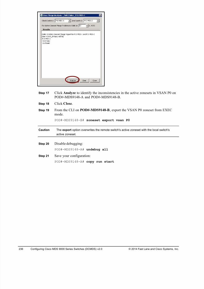
8/18/2019 FL_DCMDS_2.0.3_LG(1).pdf
http://slidepdf.com/reader/full/fldcmds203lg1pdf 236/482
236 Configuring Cisco MDS 9000 Series Switches (DCMDS) v2.0 © 2014 Fast Lane and Cisco Systems, Inc.
Step 17 Click Analyze to identify the inconsistencies in the active zonesets in VSAN P0 on
POD#-MDS9148-A and POD#-MDS9148-B.
Step 18 Click Close.
Step 19 From the CLI on POD#-MDS9148-B, export the VSAN P0 zoneset from EXEC
mode.
POD#-MDS9148-B# zoneset export vsan P0
Caution The export option overwrites the remote switch's active zoneset with the local switch's
active zoneset.
Step 20 Disable debugging:
POD#-MDS9148-A# undebug all
Step 21 Save your configuration:
POD#-MDS9148-A# copy run start
8/18/2019 FL_DCMDS_2.0.3_LG(1).pdf
http://slidepdf.com/reader/full/fldcmds203lg1pdf 237/482
Configuring Cisco MDS 9000 Series Switches (DCMDS) v2.0 Fast Lane Lab Guide 2.0.3 237
Activity Verification
Complete the following steps to verify your configuration.
Step 1 Display the trunk VSAN status on your ISLs.
POD#-MDS9148-A# show interface fc1/1, fc1/7, fc1/13 trunk vsan
fc1/11 is trunking
Vsan 1 is up (None)
Vsan P0 is up (None)
…
fc1/12 is trunking
Vsan 1 is up (None)
Vsan P0 is up (None)
…
Step 2 There should be no isolated VSANs.
Step 3 On both switches, display the active zonesets and configured zonesets, and compare
the results from both switches.
POD#-MDS9148-A# show zoneset active
POD#-MDS9148-B# show zoneset active
The zonesets on both switches should now be identical.
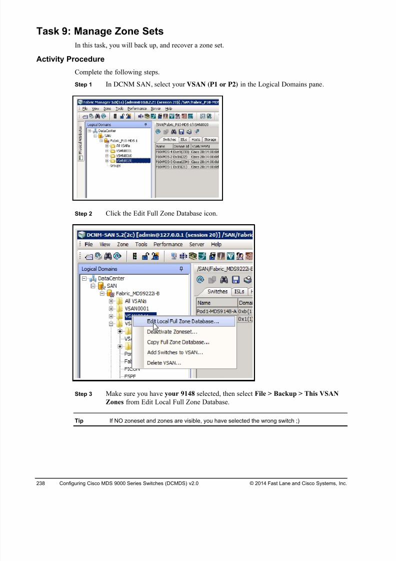
8/18/2019 FL_DCMDS_2.0.3_LG(1).pdf
http://slidepdf.com/reader/full/fldcmds203lg1pdf 238/482
238 Configuring Cisco MDS 9000 Series Switches (DCMDS) v2.0 © 2014 Fast Lane and Cisco Systems, Inc.
Task 9: Manage Zone Sets
In this task, you will back up, and recover a zone set.
Activity Procedure
Complete the following steps.
Step 1 In DCNM SAN, select your VSAN (P1 or P2) in the Logical Domains pane.
Step 2 Click the Edit Full Zone Database icon.
Step 3 Make sure you have your 9148 selected, then select File > Backup > This VSANZones from Edit Local Full Zone Database.
Tip If NO zoneset and zones are visible, you have selected the wrong switch ;)
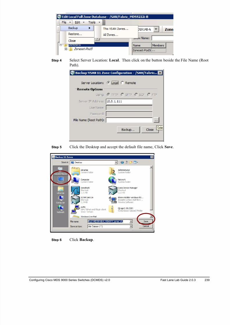
8/18/2019 FL_DCMDS_2.0.3_LG(1).pdf
http://slidepdf.com/reader/full/fldcmds203lg1pdf 239/482
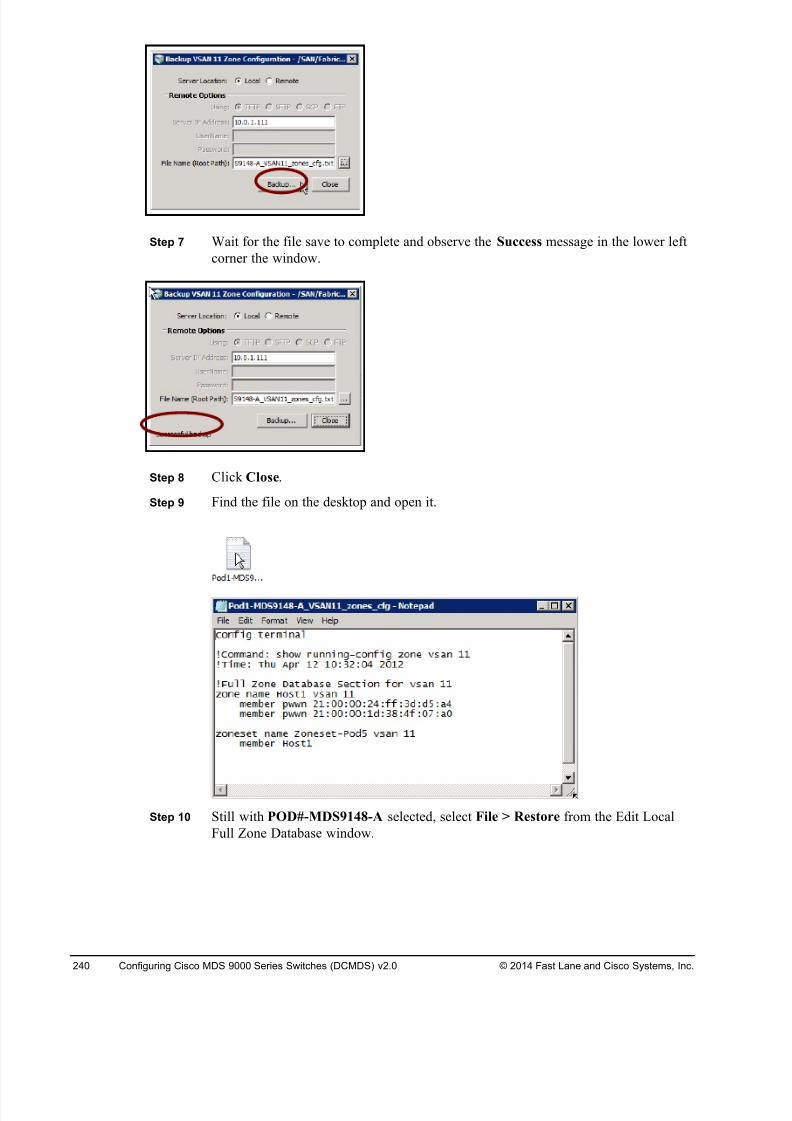
8/18/2019 FL_DCMDS_2.0.3_LG(1).pdf
http://slidepdf.com/reader/full/fldcmds203lg1pdf 240/482
240 Configuring Cisco MDS 9000 Series Switches (DCMDS) v2.0 © 2014 Fast Lane and Cisco Systems, Inc.
Step 7 Wait for the file save to complete and observe the Success message in the lower left
corner the window.
Step 8 Click Close.
Step 9 Find the file on the desktop and open it.
Step 10 Still with POD#-MDS9148-A selected, select File > Restore from the Edit Local
Full Zone Database window.
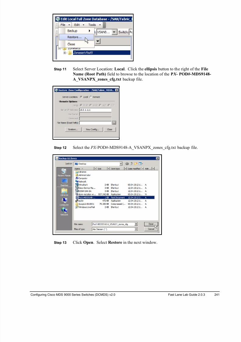
8/18/2019 FL_DCMDS_2.0.3_LG(1).pdf
http://slidepdf.com/reader/full/fldcmds203lg1pdf 241/482
Configuring Cisco MDS 9000 Series Switches (DCMDS) v2.0 Fast Lane Lab Guide 2.0.3 241
Step 11 Select Server Location: Local. Click the ellipsis button to the right of the File
Name (Root Path) field to browse to the location of the P X - POD#-MDS9148-
A_VSANPX_zones_cfg.txt backup file.
Step 12 Select the PX-POD#-MDS9148-A_VSANPX_zones_cfg.txt backup file.
Step 13 Click Open. Select Restore in the next window.
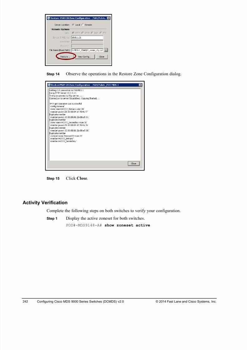
8/18/2019 FL_DCMDS_2.0.3_LG(1).pdf
http://slidepdf.com/reader/full/fldcmds203lg1pdf 242/482
242 Configuring Cisco MDS 9000 Series Switches (DCMDS) v2.0 © 2014 Fast Lane and Cisco Systems, Inc.
Step 14 Observe the operations in the Restore Zone Configuration dialog.
Step 15 Click Close.
Activity Verification
Complete the following steps on both switches to verify your configuration.
Step 1 Display the active zoneset for both switches.
POD#-MDS9148-A# show zoneset active
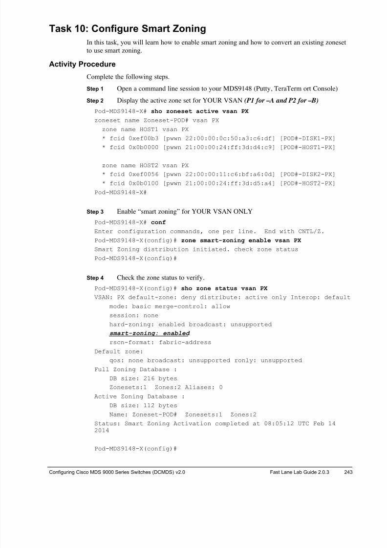
8/18/2019 FL_DCMDS_2.0.3_LG(1).pdf
http://slidepdf.com/reader/full/fldcmds203lg1pdf 243/482
Configuring Cisco MDS 9000 Series Switches (DCMDS) v2.0 Fast Lane Lab Guide 2.0.3 243
Task 10: Configure
Smart Zoning
In this task, you will learn how to enable smart zoning and how to convert an existing zoneset
to use smart zoning.
Activity Procedure
Complete the following steps.
Step 1 Open a command line session to your MDS9148 (Putty, TeraTerm ort Console)
Step 2 Display the active zone set for YOUR VSAN (P1 for –A and P2 for –B)
Pod-MDS9148-X# sho zoneset active vsan PX
zoneset name Zoneset-POD# vsan PX
zone name HOST1 vsan PX
* fcid 0xef00b3 [pwwn 22:00:00:0c:50:a3:c6:df] [POD#-DISK1-PX]
* fcid 0x0b0000 [pwwn 21:00:00:24:ff:3d:d4:c9] [POD#-HOST1-PX]
zone name HOST2 vsan PX
* fcid 0xef0056 [pwwn 22:00:00:11:c6:bf:a6:0d] [POD#-DISK2-PX]
* fcid 0x0b0100 [pwwn 21:00:00:24:ff:3d:d5:a4] [POD#-HOST2-PX]
Pod-MDS9148-X#
Step 3 Enable “smart zoning” for YOUR VSAN ONLY
Pod-MDS9148-X# conf
Enter configuration commands, one per line. End with CNTL/Z.
Pod-MDS9148-X(config)# zone smart-zoning enable vsan PX
Smart Zoning distribution initiated. check zone status
Pod-MDS9148-X(config)#
Step 4 Check the zone status to verify.
Pod-MDS9148-X(config)# sho zone status vsan PX VSAN: PX default-zone: deny distribute: active only Interop: default
mode: basic merge-control: allow
session: none
hard-zoning: enabled broadcast: unsupported
smart-zoning: enabled
rscn-format: fabric-address
Default zone:
qos: none broadcast: unsupported ronly: unsupported
Full Zoning Database :
DB size: 216 bytes
Zonesets:1 Zones:2 Aliases: 0
Active Zoning Database :
DB size: 112 bytes
Name: Zoneset-POD# Zonesets:1 Zones:2
Status: Smart Zoning Activation completed at 08:05:12 UTC Feb 142014
Pod-MDS9148-X(config)#
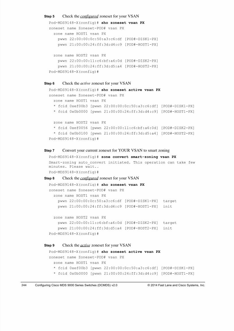
8/18/2019 FL_DCMDS_2.0.3_LG(1).pdf
http://slidepdf.com/reader/full/fldcmds203lg1pdf 244/482
244 Configuring Cisco MDS 9000 Series Switches (DCMDS) v2.0 © 2014 Fast Lane and Cisco Systems, Inc.
Step 5 Check the configured zoneset for your VSAN
Pod-MDS9148-X(config)# sho zoneset vsan PX
zoneset name Zoneset-POD# vsan PX
zone name HOST1 vsan PX
pwwn 22:00:00:0c:50:a3:c6:df [POD#-DISK1-PX]
pwwn 21:00:00:24:ff:3d:d4:c9 [POD#-HOST1-PX]
zone name HOST2 vsan PX
pwwn 22:00:00:11:c6:bf:a6:0d [POD#-DISK2-PX]
pwwn 21:00:00:24:ff:3d:d5:a4 [POD#-HOST2-PX]
Pod-MDS9148-X(config)#
Step 6 Check the active zoneset for your VSAN
Pod-MDS9148-X(config)# sho zoneset active vsan PX
zoneset name Zoneset-POD# vsan PX
zone name HOST1 vsan PX
* fcid 0xef00b3 [pwwn 22:00:00:0c:50:a3:c6:df] [POD#-DISK1-PX]
* fcid 0x0b0000 [pwwn 21:00:00:24:ff:3d:d4:c9] [POD#-HOST1-PX]
zone name HOST2 vsan PX
* fcid 0xef0056 [pwwn 22:00:00:11:c6:bf:a6:0d] [POD#-DISK2-PX]
* fcid 0x0b0100 [pwwn 21:00:00:24:ff:3d:d5:a4] [POD#-HOST2-PX]
Pod-MDS9148-X(config)#
Step 7 Convert your current zoneset for YOUR VSAN to smart zoning
Pod-MDS9148-X(config)# zone convert smart-zoning vsan PX
Smart-zoning auto_convert initiated. This operation can take fewminutes. Please wait..
Pod-MDS9148-X(config)#Step 8 Check the configured zoneset for your VSAN
Pod-MDS9148-X(config)# sho zoneset vsan PX
zoneset name Zoneset-POD# vsan PX
zone name HOST1 vsan PX
pwwn 22:00:00:0c:50:a3:c6:df [POD#-DISK1-PX] target
pwwn 21:00:00:24:ff:3d:d4:c9 [POD#-HOST1-PX] init
zone name HOST2 vsan PX
pwwn 22:00:00:11:c6:bf:a6:0d [POD#-DISK2-PX] target
pwwn 21:00:00:24:ff:3d:d5:a4 [POD#-HOST2-PX] init
Pod-MDS9148-X(config)#
Step 9 Check the active zoneset for your VSAN
Pod-MDS9148-X(config)# sho zoneset active vsan PX
zoneset name Zoneset-POD# vsan PX
zone name HOST1 vsan PX
* fcid 0xef00b3 [pwwn 22:00:00:0c:50:a3:c6:df] [POD#-DISK1-PX]
* fcid 0x0b0000 [pwwn 21:00:00:24:ff:3d:d4:c9] [POD#-HOST1-PX]
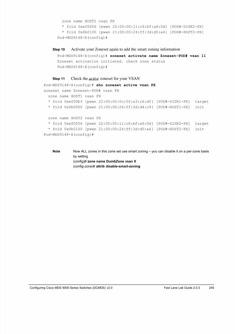
8/18/2019 FL_DCMDS_2.0.3_LG(1).pdf
http://slidepdf.com/reader/full/fldcmds203lg1pdf 245/482
Configuring Cisco MDS 9000 Series Switches (DCMDS) v2.0 Fast Lane Lab Guide 2.0.3 245
zone name HOST2 vsan PX
* fcid 0xef0056 [pwwn 22:00:00:11:c6:bf:a6:0d] [POD#-DISK2-PX]
* fcid 0x0b0100 [pwwn 21:00:00:24:ff:3d:d5:a4] [POD#-HOST2-PX]
Pod-MDS9148-X(config)#
Step 10 Activate your Zoneset again to add the smart zoning information
Pod-MDS9148-X(config)# zoneset activate name Zoneset-POD# vsan 11
Zoneset activation initiated. check zone status
Pod-MDS9148-X(config)#
Step 11 Check the active zoneset for your VSAN
Pod-MDS9148-X(config)# sho zoneset active vsan PX
zoneset name Zoneset-POD# vsan PX
zone name HOST1 vsan PX
* fcid 0xef00b3 [pwwn 22:00:00:0c:50:a3:c6:df] [POD#-DISK1-PX] target
* fcid 0x0b0000 [pwwn 21:00:00:24:ff:3d:d4:c9] [POD#-HOST1-PX] init
zone name HOST2 vsan PX
* fcid 0xef0056 [pwwn 22:00:00:11:c6:bf:a6:0d] [POD#-DISK2-PX] target
* fcid 0x0b0100 [pwwn 21:00:00:24:ff:3d:d5:a4] [POD#-HOST2-PX] init
Pod-MDS9148-X(config)#
Note Now ALL zones in this zone set use smart zoning – you can disable it on a per-zone basis
by setting
(config)# zone name DumbZone vsan X
(config-zone)# attrib disable-smart-zoning
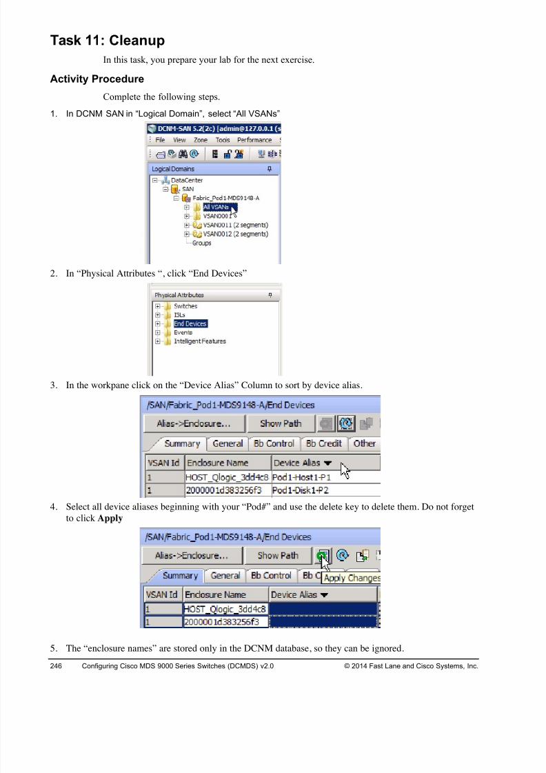
8/18/2019 FL_DCMDS_2.0.3_LG(1).pdf
http://slidepdf.com/reader/full/fldcmds203lg1pdf 246/482
246 Configuring Cisco MDS 9000 Series Switches (DCMDS) v2.0 © 2014 Fast Lane and Cisco Systems, Inc.
Task 11: Cleanup
In this task, you prepare your lab for the next exercise.
Activity Procedure
Complete the following steps.
1. In DCNM SAN in “Logical Domain”, select “All VSANs”
2. In “Physical Attributes “, click “End Devices”
3. In the workpane click on the “Device Alias” Column to sort by device alias.
4. Select all device aliases beginning with your “Pod#” and use the delete key to delete them. Do not forget
to click Apply
5. The “enclosure names” are stored only in the DCNM database, so they can be ignored.
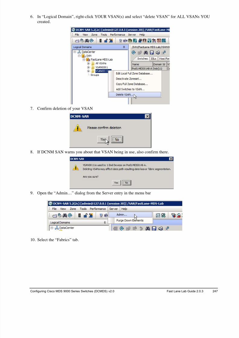
8/18/2019 FL_DCMDS_2.0.3_LG(1).pdf
http://slidepdf.com/reader/full/fldcmds203lg1pdf 247/482
Configuring Cisco MDS 9000 Series Switches (DCMDS) v2.0 Fast Lane Lab Guide 2.0.3 247
6. In “Logical Domain”, right-click YOUR VSAN(s) and select “delete VSAN” for ALL VSANs YOU
created.
7. Confirm deletion of your VSAN
8. If DCNM SAN warns you about that VSAN being in use, also confirm there.
9. Open the “Admin…” dialog from the Server entry in the menu bar
10. Select the “Fabrics” tab.
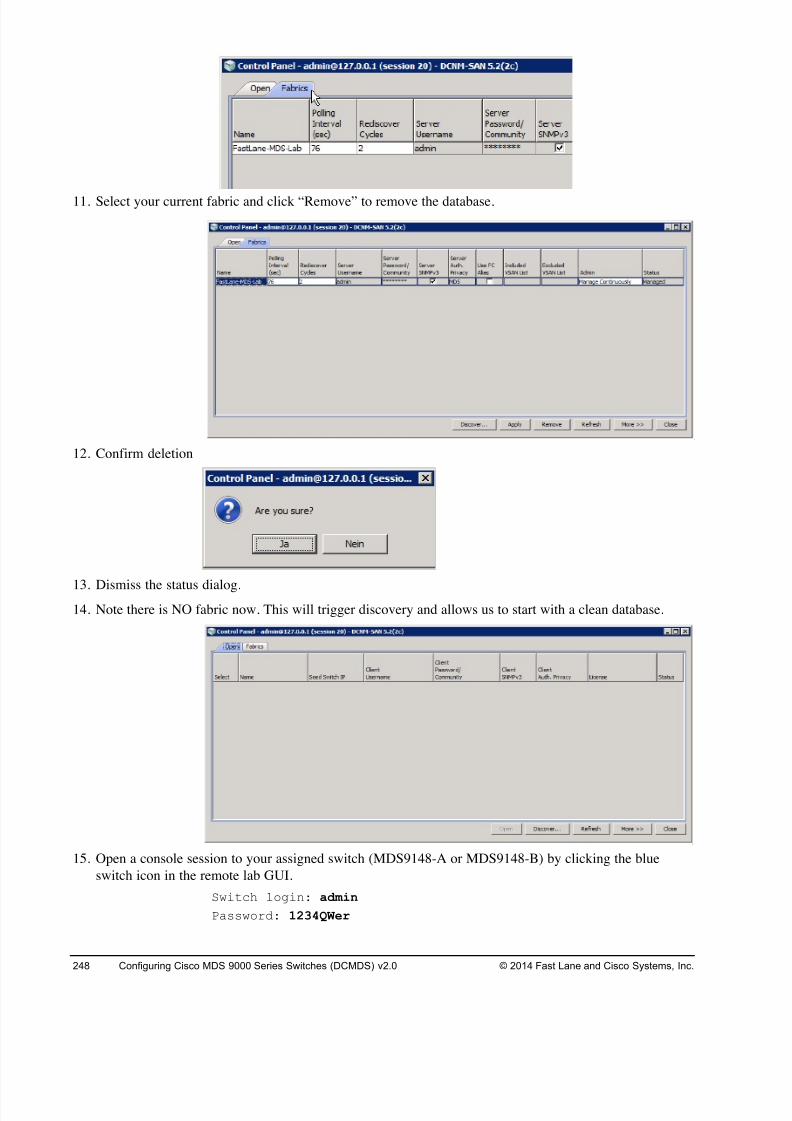
8/18/2019 FL_DCMDS_2.0.3_LG(1).pdf
http://slidepdf.com/reader/full/fldcmds203lg1pdf 248/482
248 Configuring Cisco MDS 9000 Series Switches (DCMDS) v2.0 © 2014 Fast Lane and Cisco Systems, Inc.
11. Select your current fabric and click “Remove” to remove the database.
12. Confirm deletion
13. Dismiss the status dialog.14. Note there is NO fabric now. This will trigger discovery and allows us to start with a clean database.
15. Open a console session to your assigned switch (MDS9148-A or MDS9148-B) by clicking the blue
switch icon in the remote lab GUI.
Switch login: admin
Password: 1234QWer

8/18/2019 FL_DCMDS_2.0.3_LG(1).pdf
http://slidepdf.com/reader/full/fldcmds203lg1pdf 249/482
Configuring Cisco MDS 9000 Series Switches (DCMDS) v2.0 Fast Lane Lab Guide 2.0.3 249
16. Clear the current startup configuration ON YOUR 9148s ONLY, DO NOT CLEAR THE CORE
9222is!!! .
# write erase
The following message is displayed:
Warning: This command will erase the startup-configuration.
Do you wish to proceed anyway? [y/n] [N]
Type y to proceed.
17. Reboot the 9148 switch.
# reload
This command will reboot the system. (y/n)?
Type y to proceed.
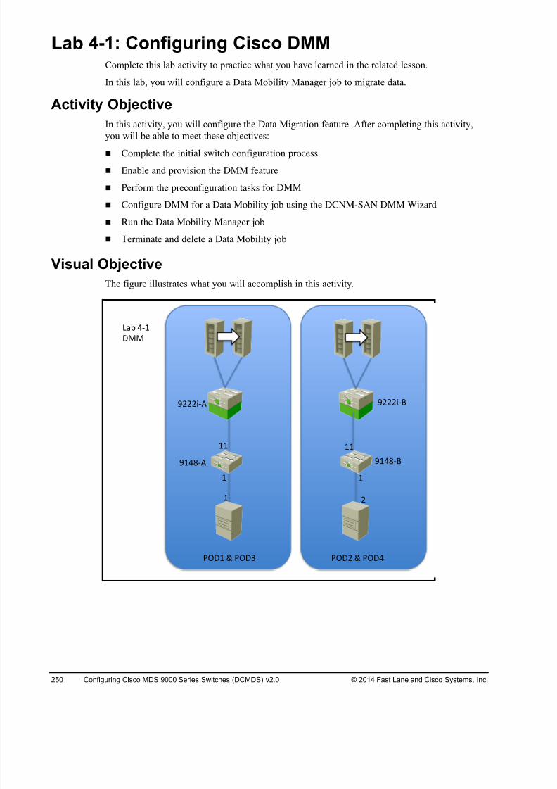
8/18/2019 FL_DCMDS_2.0.3_LG(1).pdf
http://slidepdf.com/reader/full/fldcmds203lg1pdf 250/482
250 Configuring Cisco MDS 9000 Series Switches (DCMDS) v2.0 © 2014 Fast Lane and Cisco Systems, Inc.
Lab 4-1: Configuring Cisco DMM Complete this lab activity to practice what you have learned in the related lesson.
In this lab, you will configure a Data Mobility Manager job to migrate data.
Activity Objective
In this activity, you will configure the Data Migration feature. After completing this activity,
you will be able to meet these objectives:
! Complete the initial switch configuration process
! Enable and provision the DMM feature
! Perform the preconfiguration tasks for DMM
! Configure DMM for a Data Mobility job using the DCNM-SAN DMM Wizard
! Run the Data Mobility Manager job
! Terminate and delete a Data Mobility job
Visual Objective
The figure illustrates what you will accomplish in this activity.
! !
!!!!
! #
$!%&'( $!%&')
$###*'( $###*')
+,- %'!.
/00
12/! 3 12/4 12/# 3 12/%
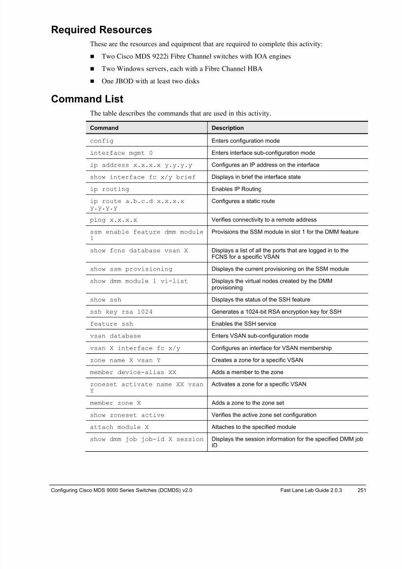
8/18/2019 FL_DCMDS_2.0.3_LG(1).pdf
http://slidepdf.com/reader/full/fldcmds203lg1pdf 251/482
Configuring Cisco MDS 9000 Series Switches (DCMDS) v2.0 Fast Lane Lab Guide 2.0.3 251
Required Resources
These are the resources and equipment that are required to complete this activity:
! Two Cisco MDS 9222i Fibre Channel switches with IOA engines
! Two Windows servers, each with a Fibre Channel HBA
! One JBOD with at least two disks
Command List The table describes the commands that are used in this activity.
Command Description
config Enters configuration mode
interface mgmt 0 Enters interface sub-configuration mode
ip address x.x.x.x y.y.y.y Configures an IP address on the interface
show interface fc x/y brief Displays in brief the interface state
ip routing Enables IP Routing
ip route a.b.c.d x.x.x.xy.y.y.y
Configures a static route
ping x.x.x.x Verifies connectivity to a remote address
ssm enable feature dmm module1
Provisions the SSM module in slot 1 for the DMM feature
show fcns database vsan X Displays a list of all the ports that are logged in to theFCNS for a specific VSAN
show ssm provisioning Displays the current provisioning on the SSM module
show dmm module 1 vi-list Displays the virtual nodes created by the DMMprovisioning
show ssh Displays the status of the SSH feature
ssh key rsa 1024 Generates a 1024-bit RSA encryption key for SSH
feature ssh Enables the SSH service
vsan database Enters VSAN sub-configuration mode
vsan X interface fc x/y Configures an interface for VSAN membership
zone name X vsan Y Creates a zone for a specific VSAN
member device-alias XX Adds a member to the zone
zoneset activate name XX vsanY
Activates a zone for a specific VSAN
member zone X Adds a zone to the zone set
show zoneset active Verifies the active zone set configuration
attach module X Attaches to the specified module
show dmm job job-id X session Displays the session information for the specified DMM jobID
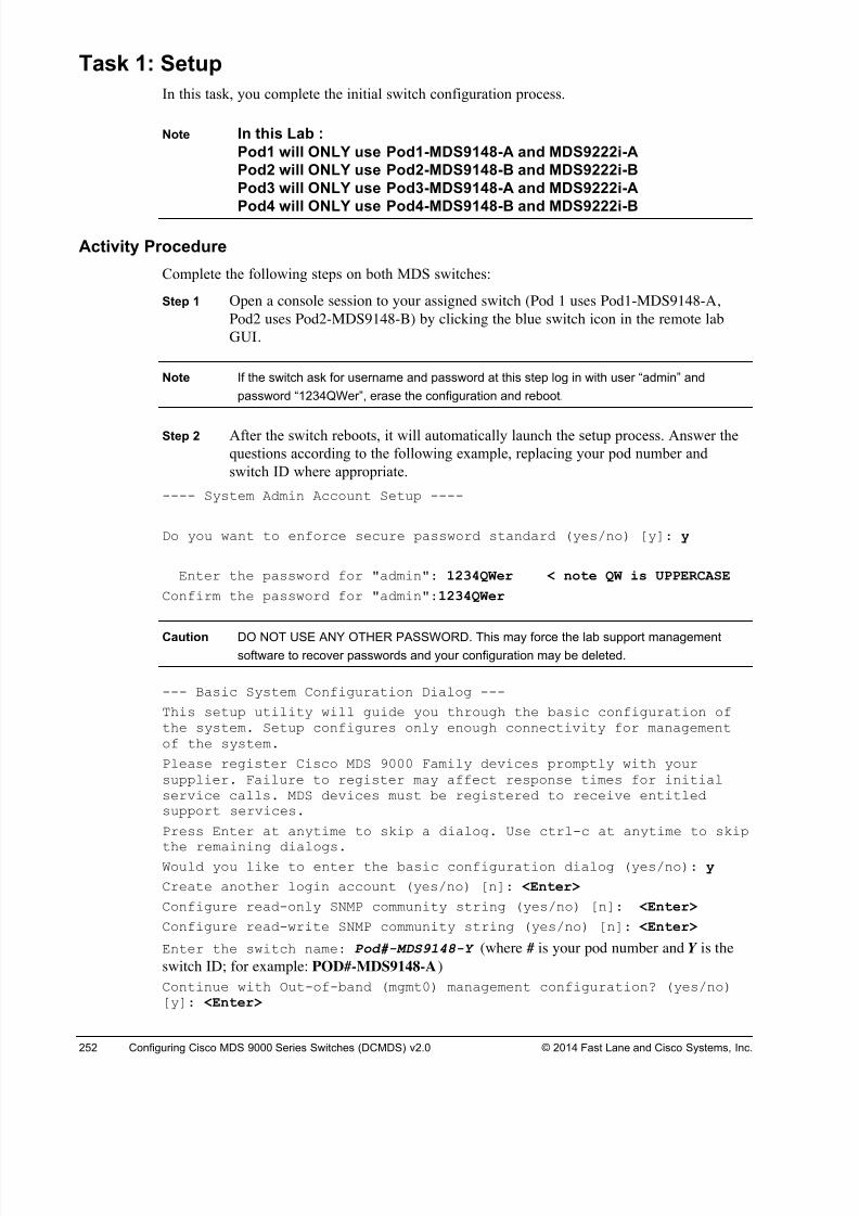
8/18/2019 FL_DCMDS_2.0.3_LG(1).pdf
http://slidepdf.com/reader/full/fldcmds203lg1pdf 252/482
252 Configuring Cisco MDS 9000 Series Switches (DCMDS) v2.0 © 2014 Fast Lane and Cisco Systems, Inc.
Task 1: Setup
In this task, you complete the initial switch configuration process.
Note In this Lab :
Pod1 will ONLY use Pod1-MDS9148-A and MDS9222i-A
Pod2 will ONLY use Pod2-MDS9148-B and MDS9222i-B
Pod3 will ONLY use Pod3-MDS9148-A and MDS9222i-A
Pod4 will ONLY use Pod4-MDS9148-B and MDS9222i-B
Activity Procedure
Complete the following steps on both MDS switches:
Step 1 Open a console session to your assigned switch (Pod 1 uses Pod1-MDS9148-A,
Pod2 uses Pod2-MDS9148-B) by clicking the blue switch icon in the remote lab
GUI.
Note If the switch ask for username and password at this step log in with user “admin” and
password “1234QWer”, erase the configuration and reboot.
Step 2 After the switch reboots, it will automatically launch the setup process. Answer the
questions according to the following example, replacing your pod number and
switch ID where appropriate.
---- System Admin Account Setup ----
Do you want to enforce secure password standard (yes/no) [y]: y
Enter the password for "admin": 1234QWer < note QW is UPPERCASE
Confirm the password for "admin":1234QWer
Caution DO NOT USE ANY OTHER PASSWORD. This may force the lab support managementsoftware to recover passwords and your configuration may be deleted.
--- Basic System Configuration Dialog ---
This setup utility will guide you through the basic configuration ofthe system. Setup configures only enough connectivity for managementof the system.
Please register Cisco MDS 9000 Family devices promptly with yoursupplier. Failure to register may affect response times for initialservice calls. MDS devices must be registered to receive entitledsupport services.
Press Enter at anytime to skip a dialog. Use ctrl-c at anytime to skip
the remaining dialogs.Would you like to enter the basic configuration dialog (yes/no): y
Create another login account (yes/no) [n]: <Enter>
Configure read-only SNMP community string (yes/no) [n]: <Enter>
Configure read-write SNMP community string (yes/no) [n]: <Enter>
Enter the switch name: Pod#-MDS9148-Y (where # is your pod number and Y is the
switch ID; for example: POD#-MDS9148-A)
Continue with Out-of-band (mgmt0) management configuration? (yes/no)[y]: <Enter>
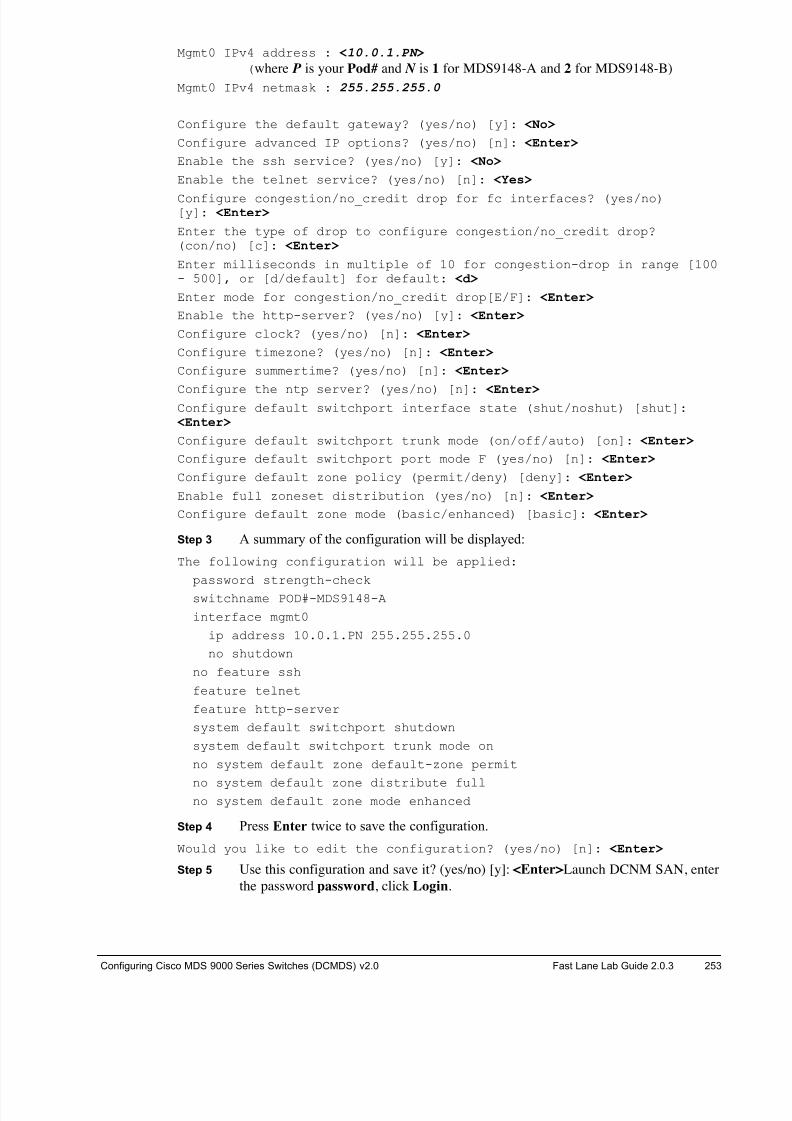
8/18/2019 FL_DCMDS_2.0.3_LG(1).pdf
http://slidepdf.com/reader/full/fldcmds203lg1pdf 253/482
Configuring Cisco MDS 9000 Series Switches (DCMDS) v2.0 Fast Lane Lab Guide 2.0.3 253
Mgmt0 IPv4 address : <10.0.1.PN >
(where P is your Pod# and N is 1 for MDS9148-A and 2 for MDS9148-B)
Mgmt0 IPv4 netmask : 255.255.255.0
Configure the default gateway? (yes/no) [y]: <No>
Configure advanced IP options? (yes/no) [n]: <Enter>
Enable the ssh service? (yes/no) [y]: <No>
Enable the telnet service? (yes/no) [n]: <Yes>
Configure congestion/no_credit drop for fc interfaces? (yes/no)[y]: <Enter>
Enter the type of drop to configure congestion/no_credit drop?(con/no) [c]: <Enter>
Enter milliseconds in multiple of 10 for congestion-drop in range [100- 500], or [d/default] for default: <d>
Enter mode for congestion/no_credit drop[E/F]: <Enter>
Enable the http-server? (yes/no) [y]: <Enter>
Configure clock? (yes/no) [n]: <Enter>
Configure timezone? (yes/no) [n]: <Enter>
Configure summertime? (yes/no) [n]: <Enter>
Configure the ntp server? (yes/no) [n]: <Enter>Configure default switchport interface state (shut/noshut) [shut]:
<Enter>
Configure default switchport trunk mode (on/off/auto) [on]: <Enter>
Configure default switchport port mode F (yes/no) [n]: <Enter>
Configure default zone policy (permit/deny) [deny]: <Enter>
Enable full zoneset distribution (yes/no) [n]: <Enter>
Configure default zone mode (basic/enhanced) [basic]: <Enter>
Step 3 A summary of the configuration will be displayed:
The following configuration will be applied:
password strength-check
switchname POD#-MDS9148-A
interface mgmt0
ip address 10.0.1.PN 255.255.255.0
no shutdown
no feature ssh
feature telnet
feature http-server
system default switchport shutdown
system default switchport trunk mode on
no system default zone default-zone permit
no system default zone distribute fullno system default zone mode enhanced
Step 4 Press Enter twice to save the configuration.
Would you like to edit the configuration? (yes/no) [n]: <Enter>
Step 5 Use this configuration and save it? (yes/no) [y]: <Enter>Launch DCNM SAN, enter
the password password, click Login.
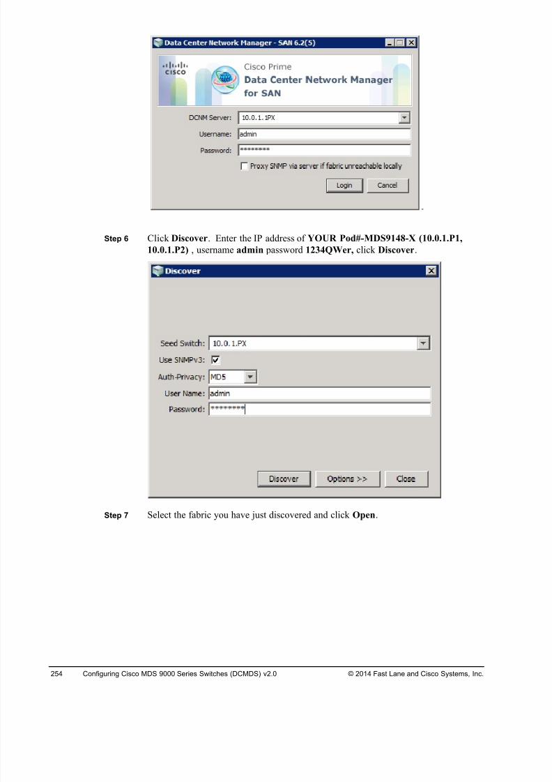
8/18/2019 FL_DCMDS_2.0.3_LG(1).pdf
http://slidepdf.com/reader/full/fldcmds203lg1pdf 254/482
254 Configuring Cisco MDS 9000 Series Switches (DCMDS) v2.0 © 2014 Fast Lane and Cisco Systems, Inc.
Step 6 Click Discover. Enter the IP address of YOUR Pod#-MDS9148-X (10.0.1.P1,
10.0.1.P2) , username admin password 1234QWer, click Discover.
Step 7 Select the fabric you have just discovered and click Open.
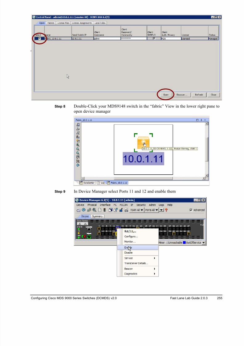
8/18/2019 FL_DCMDS_2.0.3_LG(1).pdf
http://slidepdf.com/reader/full/fldcmds203lg1pdf 255/482
Configuring Cisco MDS 9000 Series Switches (DCMDS) v2.0 Fast Lane Lab Guide 2.0.3 255
Step 8 Double-Click your MDS9148 switch in the “fabric” View in the lower right pane to
open device manager
Step 9 In Device Manager select Ports 11 and 12 and enable them
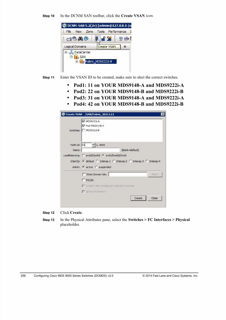
8/18/2019 FL_DCMDS_2.0.3_LG(1).pdf
http://slidepdf.com/reader/full/fldcmds203lg1pdf 256/482
256 Configuring Cisco MDS 9000 Series Switches (DCMDS) v2.0 © 2014 Fast Lane and Cisco Systems, Inc.
Step 10 In the DCNM SAN toolbar, click the Create VSAN icon.
Step 11 Enter the VSAN ID to be created, make sure to slect the correct switches.
• Pod1: 11 on YOUR MDS9148-A and MDS9222i-A
• Pod2: 22 on YOUR MDS9148-B and MDS9222i-B
• Pod3: 31 on YOUR MDS9148-A and MDS9222i-A
• Pod4: 42 on YOUR MDS9148-B and MDS9222i-B
Step 12 Click Create.
Step 13 In the Physical Attributes pane, select the Switches > FC Interfaces > Physical
placeholder.
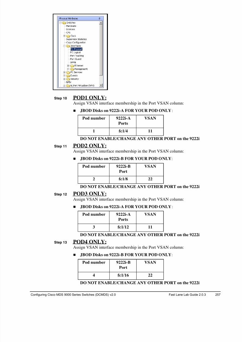
8/18/2019 FL_DCMDS_2.0.3_LG(1).pdf
http://slidepdf.com/reader/full/fldcmds203lg1pdf 257/482
Configuring Cisco MDS 9000 Series Switches (DCMDS) v2.0 Fast Lane Lab Guide 2.0.3 257
Step 10 POD1 ONLY:
Assign VSAN interface membership in the Port VSAN column:
! JBOD Disks on 9222i-A FOR YOUR POD ONLY:
Pod number 9222i-APorts VSAN
1 fc1/4 11
DO NOT ENABLE/CHANGE ANY OTHER PORT on the 9222i
Step 11 POD2 ONLY:
Assign VSAN interface membership in the Port VSAN column:
! JBOD Disks on 9222i-B FOR YOUR POD ONLY:
Pod number 9222i-B
Port
VSAN
2 fc1/8 22
DO NOT ENABLE/CHANGE ANY OTHER PORT on the 9222i
Step 12 POD3 ONLY:
Assign VSAN interface membership in the Port VSAN column:
! JBOD Disks on 9222i-A FOR YOUR POD ONLY:
Pod number 9222i-A
Ports
VSAN
3 fc1/12 11
DO NOT ENABLE/CHANGE ANY OTHER PORT on the 9222i
Step 13 POD4 ONLY:
Assign VSAN interface membership in the Port VSAN column:
! JBOD Disks on 9222i-B FOR YOUR POD ONLY:
Pod number 9222i-B
Port
VSAN
4 fc1/16 22
DO NOT ENABLE/CHANGE ANY OTHER PORT on the 9222i
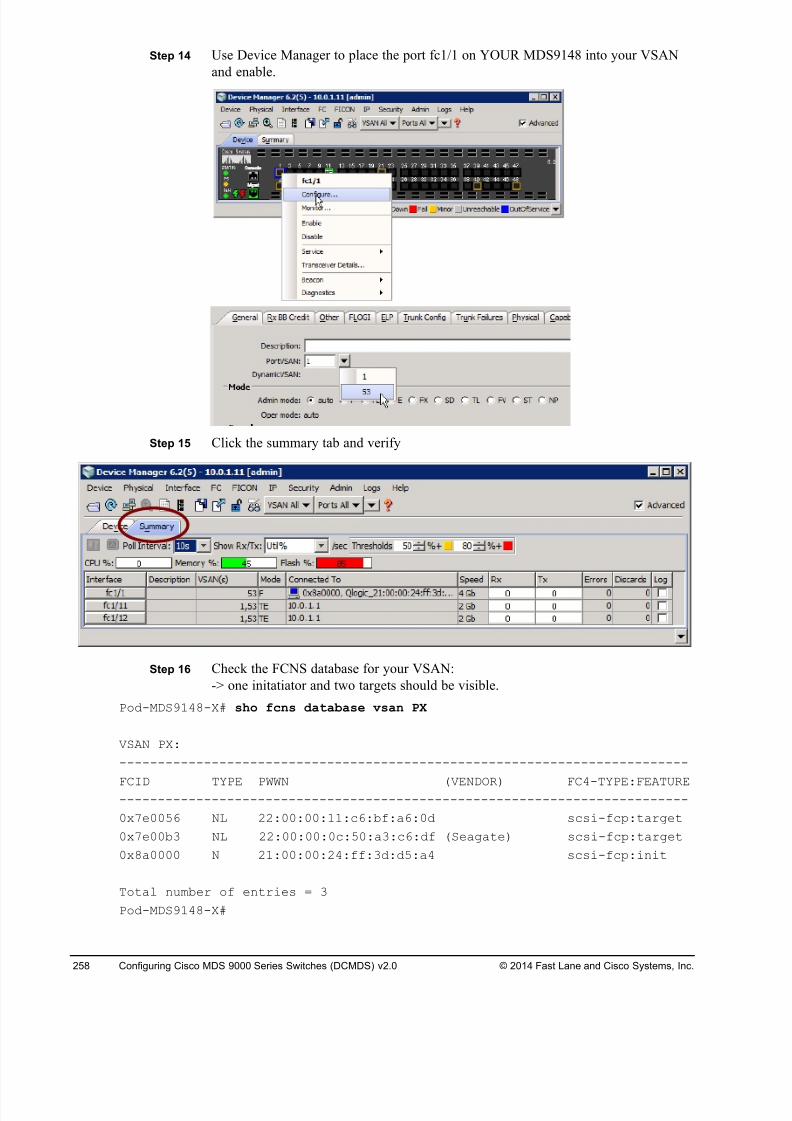
8/18/2019 FL_DCMDS_2.0.3_LG(1).pdf
http://slidepdf.com/reader/full/fldcmds203lg1pdf 258/482
8/18/2019 FL_DCMDS_2.0.3_LG(1).pdf
http://slidepdf.com/reader/full/fldcmds203lg1pdf 259/482
Configuring Cisco MDS 9000 Series Switches (DCMDS) v2.0 Fast Lane Lab Guide 2.0.3 259
Task 2: Verify the DMM Feature
In this task you will enable the IP Routing feature and provision DMM on the switches.
Note In this Lab :
Pod1 will ONLY use Pod1-MDS9148-A and MDS9222i-A
Pod2 will ONLY use Pod2-MDS9148-B and MDS9222i-B
Pod3 will ONLY use Pod3-MDS9148-A and MDS9222i-A
Pod4 will ONLY use Pod4-MDS9148-B and MDS9222i-B
Activity Procedure
Perform these tasks on both switches.
Step 1 Connect to your assigned MDS9222i (Pods 1&3 use MDS9222i-A, Pods 2&4 use
MDS9222i-B) with a Putty session.
Step 2 Confirm that the SSI image is available on the bootflash:
Pod#-MDS9148-X# dir bootflash:
300 Oct 10 08:11:25 2011 MDS20110930022644059.lic
586 Oct 10 08:11:39 2011 MDS20110930024638872.lic
582 Oct 10 08:11:53 2011 MDS20110930025213433.lic6629 May 10 14:42:32 2012 MDS9111i-A.cfg
0 Jul 07 16:37:31 2011 admin.rc.cli
49152 Mar 11 10:37:37 2013 lost+found/
15668059 Apr 17 09:32:45 2012 m9000-ek9-ssi-mz.5.2.2a.bin
19345408 May 14 05:02:10 2012 m9200-s2ek9-kickstart-mz.5.0.1a.bin
20576768 Apr 03 14:34:53 2012 m9200-s2ek9-kickstart-mz.5.2.2a.bin
98486505 May 14 05:01:51 2012 m9200-s2ek9-mz.5.0.1a.bin
99152951 Apr 03 14:38:53 2012 m9200-s2ek9-mz.5.2.2a.bin
102445 Mar 12 07:26:19 2013 mts.log
-* Some filesystem space might be used for internal purposes. *
Usage for bootflash://sup-local452497408 bytes used239849472 bytes free692346880 bytes total
Step 3 Confirm the SSI image is installed:
MDS9222i-A# sh ver module 1
ModNo Image Type SW Version SW Interim Version BIOSVersion
1 SLC 6.2(5) 6.2(5) 1.0.19
1 SSI 6.2(5) 6.2(5) n/a
MDS9222i-A#
Note The SSI image installed with install all or install all ssi bootflash:m9000-
ek9-ssi-mz.5.2.5.bin
Step 4 Verify VSAN 1 interface on your MDS9222i
MDS9222i-A# sho int vsan 1
vsan1 is up, line protocol is up
WWPN is 10:00:00:05:9b:7d:05:41, FCID is 0xed00c0
Internet address is 10.10.1.1/24
8/18/2019 FL_DCMDS_2.0.3_LG(1).pdf
http://slidepdf.com/reader/full/fldcmds203lg1pdf 260/482
260 Configuring Cisco MDS 9000 Series Switches (DCMDS) v2.0 © 2014 Fast Lane and Cisco Systems, Inc.
MTU 1500 bytes, BW 1000000 Kbit
0 packets input, 0 bytes, 0 errors, 0 multicast
6 packets output, 384 bytes, 0 errors, 0 dropped
MDS9222i-A#
Note: these are the commands whioch were entered:
MDS# conf t
MDS(config)# interface vsan 1
MDS(config-if)# ip address 10.10.1.P 255.255.255.0
MDS(config-if)# no shut
Note If more than one service engine is used static routes would have to be added.
Step 5 Verify DMM has been enabled on Enable DMM on Module 1 on your MDS9222i
MDS9222i-A(config)# sho ssm provisioning
Module Ports/Nodes Application Provisioning Status
-----------------------------------------------------------
1 1-1 dmm SUCCESS
MDS9222i-A(config)#
Note these are the commands whioch were entered:
MDS(config)# ssm enable feature dmm module 1
8/18/2019 FL_DCMDS_2.0.3_LG(1).pdf
http://slidepdf.com/reader/full/fldcmds203lg1pdf 261/482
Configuring Cisco MDS 9000 Series Switches (DCMDS) v2.0 Fast Lane Lab Guide 2.0.3 261
Activity Verification
Complete the following steps to verify your configuration.
Step 1 Verify that the virtual node was created when you enabled the DMM feature. (This
virtual node will be used later for zoning.)
MDS9222i(config)# sho dmm module 1 vi-list======================================================================DPP-Id VI-pWWN VI-nWWN Outstanding jobs======================================================================1 21:71:00:05:9b:7d:05:42 21:70:00:05:9b:7d:05:42 0MDS9222i(config)#
Step 2 Launch DCNM-SAN Client icon on the desktop.
Step 3 Open DCNM SAN Client if not already/still open.
Step 4 In DCNM-SAN, select Intelligent Features, then in the right hand pane, check both
the Summary and MSM tab. Verify YOUR DMM. (the other 9222i also shows up
here)
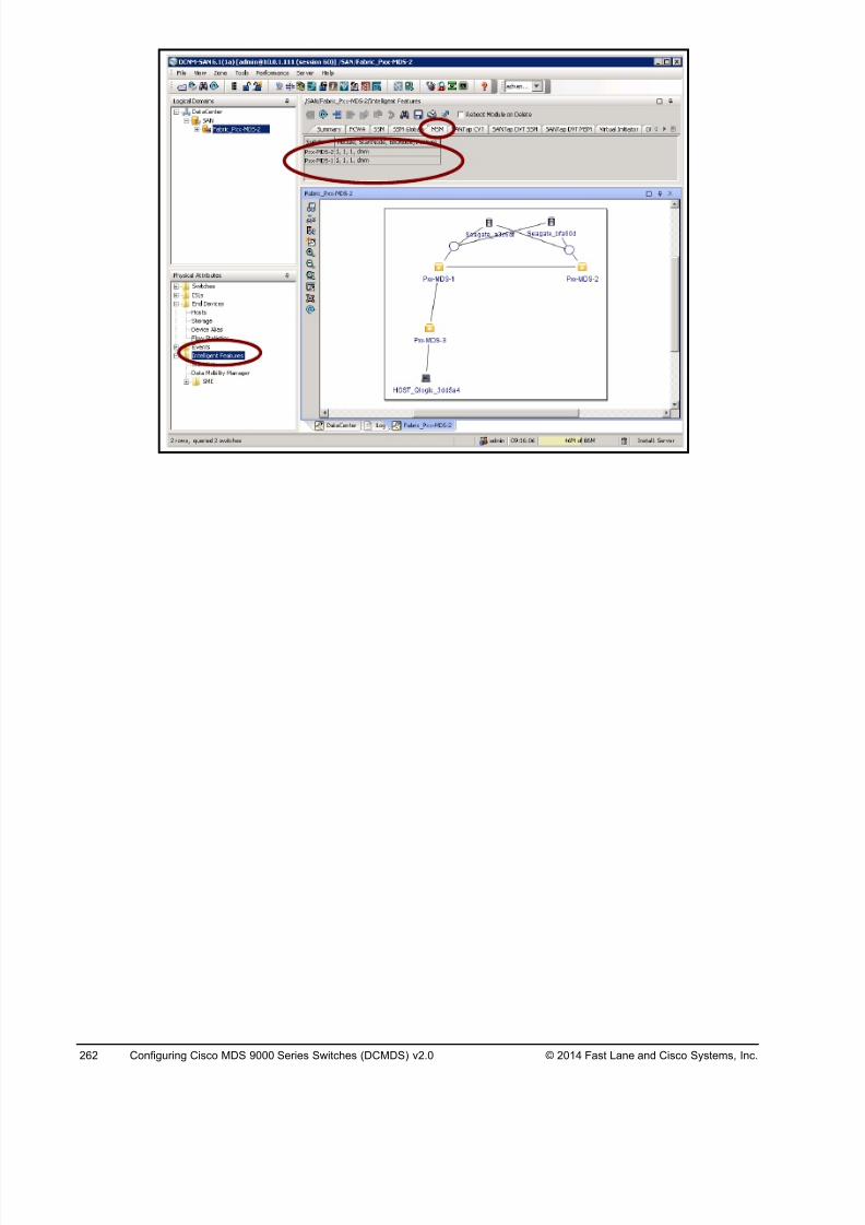
8/18/2019 FL_DCMDS_2.0.3_LG(1).pdf
http://slidepdf.com/reader/full/fldcmds203lg1pdf 262/482
262 Configuring Cisco MDS 9000 Series Switches (DCMDS) v2.0 © 2014 Fast Lane and Cisco Systems, Inc.
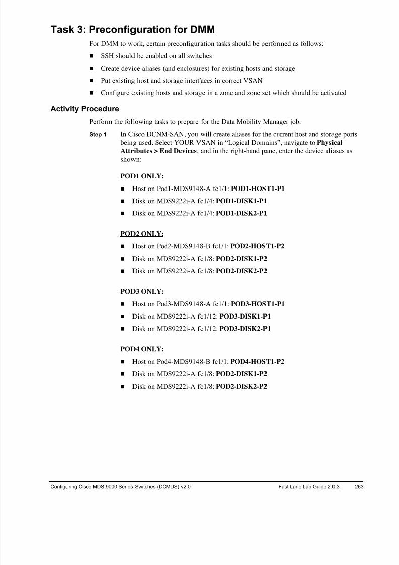
8/18/2019 FL_DCMDS_2.0.3_LG(1).pdf
http://slidepdf.com/reader/full/fldcmds203lg1pdf 263/482
Configuring Cisco MDS 9000 Series Switches (DCMDS) v2.0 Fast Lane Lab Guide 2.0.3 263
Task 3: Preconfiguration for DMM
For DMM to work, certain preconfiguration tasks should be performed as follows:
! SSH should be enabled on all switches
! Create device aliases (and enclosures) for existing hosts and storage
! Put existing host and storage interfaces in correct VSAN
! Configure existing hosts and storage in a zone and zone set which should be activated
Activity Procedure
Perform the following tasks to prepare for the Data Mobility Manager job.
Step 1 In Cisco DCNM-SAN, you will create aliases for the current host and storage ports
being used. Select YOUR VSAN in “Logical Domains”, navigate to Physical
Attributes > End Devices, and in the right-hand pane, enter the device aliases as
shown:
POD1 ONLY:
! Host on Pod1-MDS9148-A fc1/1: POD1-HOST1-P1
! Disk on MDS9222i-A fc1/4: POD1-DISK1-P1
! Disk on MDS9222i-A fc1/4: POD1-DISK2-P1
POD2 ONLY:
! Host on Pod2-MDS9148-B fc1/1: POD2-HOST1-P2
! Disk on MDS9222i-A fc1/8: POD2-DISK1-P2
! Disk on MDS9222i-A fc1/8: POD2-DISK2-P2
POD3 ONLY:
! Host on Pod3-MDS9148-A fc1/1: POD3-HOST1-P1
! Disk on MDS9222i-A fc1/12: POD3-DISK1-P1
! Disk on MDS9222i-A fc1/12: POD3-DISK2-P1
POD4 ONLY:
! Host on Pod4-MDS9148-B fc1/1: POD4-HOST1-P2
! Disk on MDS9222i-A fc1/8: POD2-DISK1-P2
! Disk on MDS9222i-A fc1/8: POD2-DISK2-P2
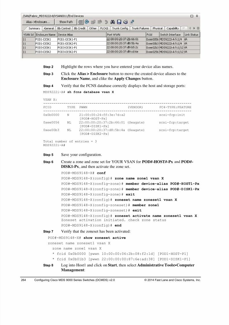
8/18/2019 FL_DCMDS_2.0.3_LG(1).pdf
http://slidepdf.com/reader/full/fldcmds203lg1pdf 264/482
264 Configuring Cisco MDS 9000 Series Switches (DCMDS) v2.0 © 2014 Fast Lane and Cisco Systems, Inc.
Step 2 Highlight the rows where you have entered your device alias names.
Step 3 Click the Alias > Enclosure button to move the created device aliases to the
Enclosure Name, and clike the Apply Changes button.
Step 4 Verify that the FCNS database correctly displays the host and storage ports:
MDS9222i-A# sh fcns database vsan X
VSAN X:--------------------------------------------------------------------------FCID TYPE PWWN (VENDOR) FC4-TYPE:FEATURE--------------------------------------------------------------------------
0x0b0000 N 21:00:00:24:ff:3e:7d:a2 scsi-fcp:init[POD#-HOST-Px]
0xee0056 NL 22:00:00:20:37:2b:66:01 (Seagate) scsi-fcp:target[POD#-DISK1-Px]
0xee00b3 NL 22:00:00:20:37:d8:5b:4a (Seagate) scsi-fcp:target[POD#-DISK2-Px]
Total number of entries = 3MDS9222i-A#
Step 5 Save your configuration.
Step 6 Create a zone and zone set for YOUR VSAN for POD#-HOST#-Px and POD#-
DISK1-Px, and then activate the zone set.
POD#-MDS9148-X# conf
POD#-MDS9148-X(config)# zone name zone1 vsan X
POD#-MDS9148-X(config-zone)# member device-alias POD#-HOST1-Px
POD#-MDS9148-X(config-zone)# member device-alias POD#-DISK1-Px
POD#-MDS9148-X(config-zone)# exit
POD#-MDS9148-X(config)# zoneset name zoneset1 vsan X
POD#-MDS9148-X(config-zoneset)# member zone1
POD#-MDS9148-X(config-zoneset)# exit
POD#-MDS9148-X(config)# zoneset activate name zoneset1 vsan X Zoneset activation initiated. check zone status
POD#-MDS9148-X(config)# end
Step 7 Verify that the zoneset has been activated:
POD#-MDS9148-X# show zoneset active
zoneset name zoneset1 vsan X
zone name zone1 vsan X
* fcid 0x0b0000 [pwwn 10:00:00:06:2b:08:f2:1d] [POD1-HOST-P1]
* fcid 0x0b01b3 [pwwn 22:00:00:00:87:6e:ad:38] [POD1-DISK1-P1]
Step 8 Log into Host1 and click on Start, then select Administrative Tools>Computer
Management:
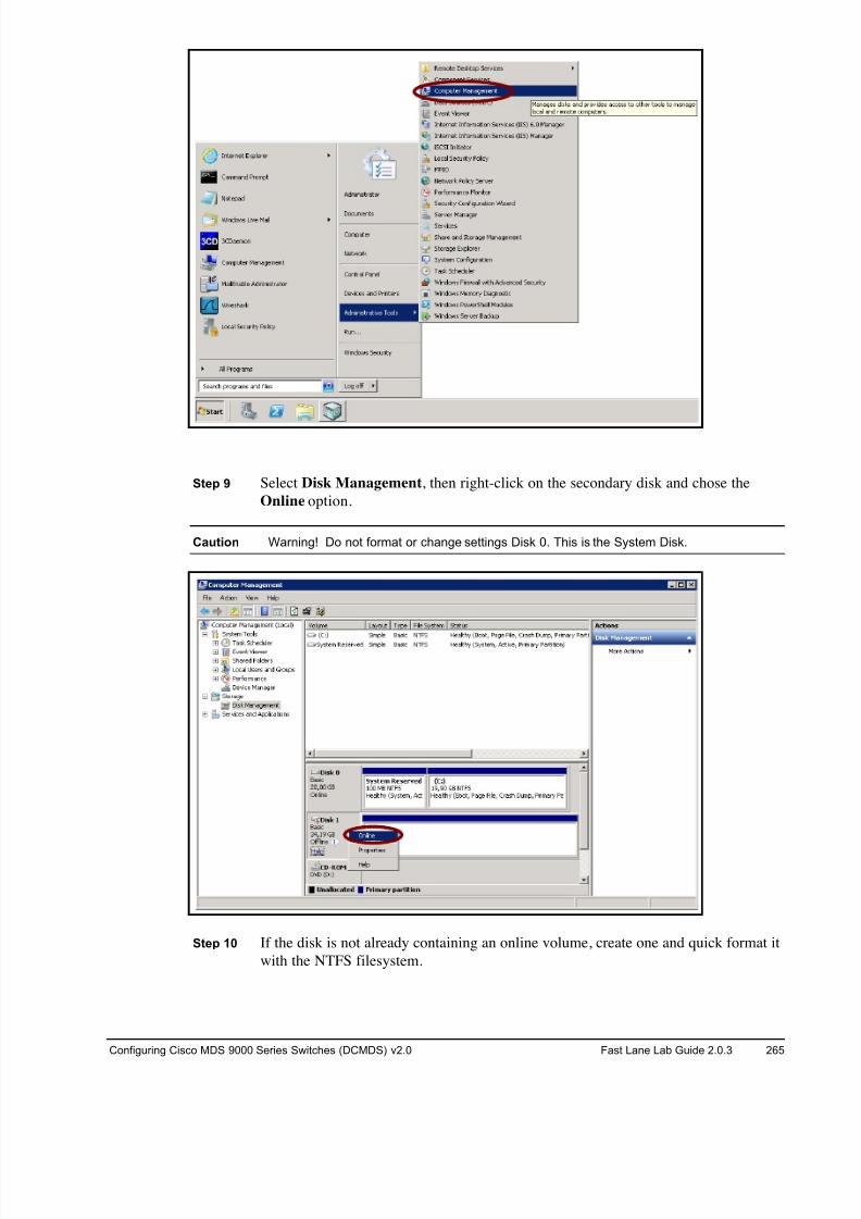
8/18/2019 FL_DCMDS_2.0.3_LG(1).pdf
http://slidepdf.com/reader/full/fldcmds203lg1pdf 265/482
Configuring Cisco MDS 9000 Series Switches (DCMDS) v2.0 Fast Lane Lab Guide 2.0.3 265
Step 9 Select Disk Management, then right-click on the secondary disk and chose the
Online option.
Caution Warning! Do not format or change settings Disk 0. This is the System Disk.
Step 10 If the disk is not already containing an online volume, create one and quick format it
with the NTFS filesystem.
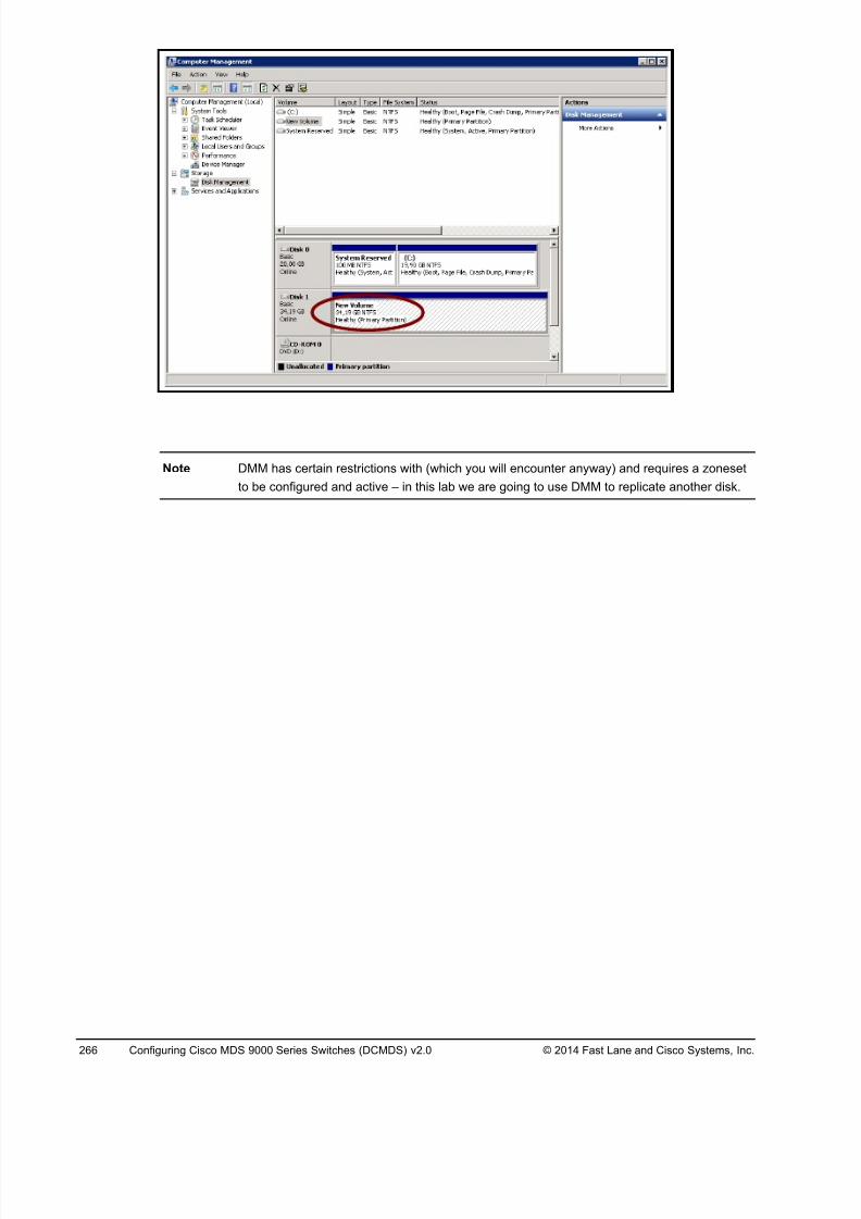
8/18/2019 FL_DCMDS_2.0.3_LG(1).pdf
http://slidepdf.com/reader/full/fldcmds203lg1pdf 266/482
266 Configuring Cisco MDS 9000 Series Switches (DCMDS) v2.0 © 2014 Fast Lane and Cisco Systems, Inc.
Note DMM has certain restrictions with (which you will encounter anyway) and requires a zoneset
to be configured and active – in this lab we are going to use DMM to replicate another disk.
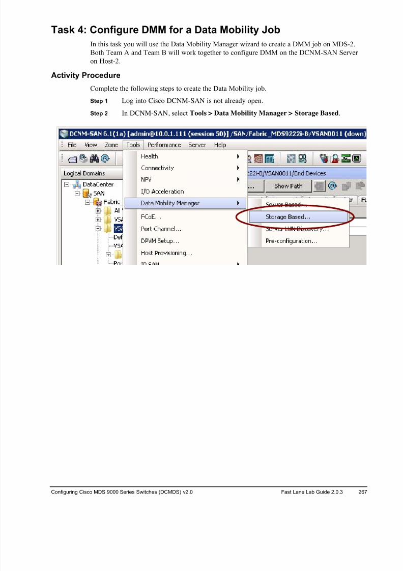
8/18/2019 FL_DCMDS_2.0.3_LG(1).pdf
http://slidepdf.com/reader/full/fldcmds203lg1pdf 267/482
Configuring Cisco MDS 9000 Series Switches (DCMDS) v2.0 Fast Lane Lab Guide 2.0.3 267
Task 4: Configure DMM for a Data Mobility Job
In this task you will use the Data Mobility Manager wizard to create a DMM job on MDS-2.
Both Team A and Team B will work together to configure DMM on the DCNM-SAN Server
on Host-2.
Activity Procedure
Complete the following steps to create the Data Mobility job.
Step 1 Log into Cisco DCNM-SAN is not already open.
Step 2 In DCNM-SAN, select Tools > Data Mobility Manager > Storage Based.
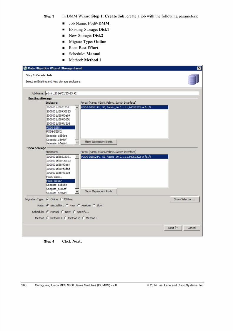
8/18/2019 FL_DCMDS_2.0.3_LG(1).pdf
http://slidepdf.com/reader/full/fldcmds203lg1pdf 268/482
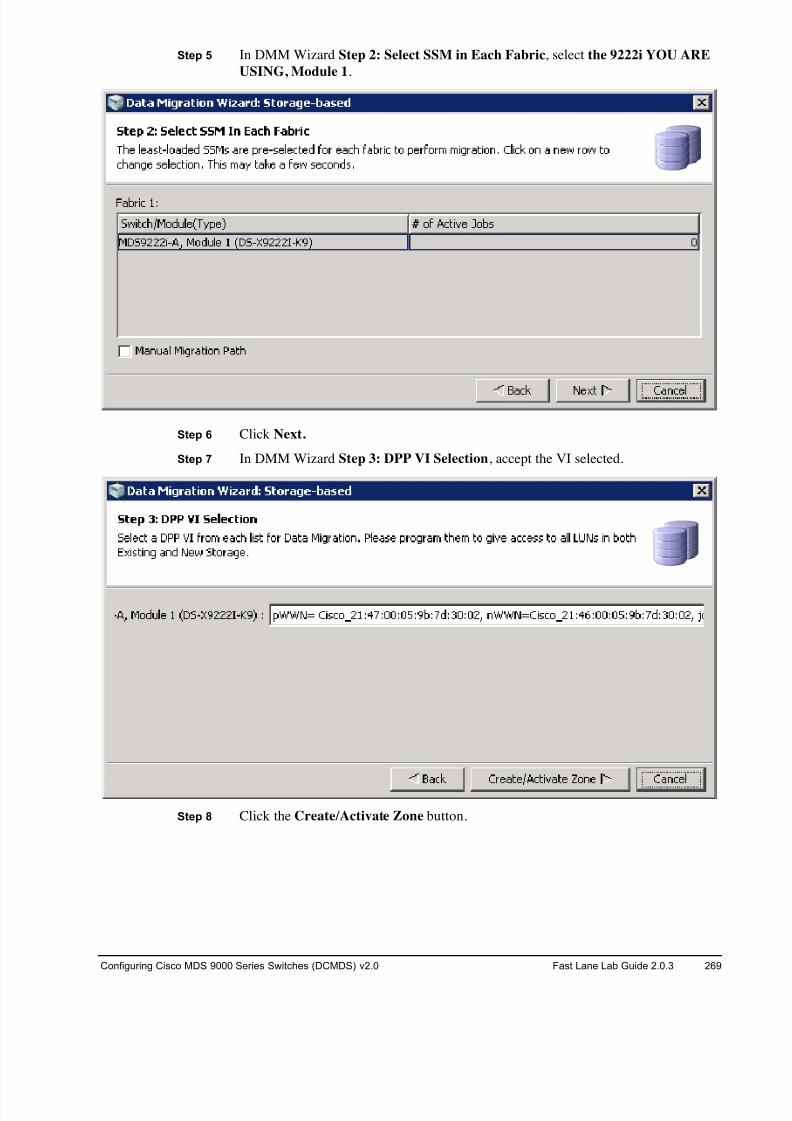
8/18/2019 FL_DCMDS_2.0.3_LG(1).pdf
http://slidepdf.com/reader/full/fldcmds203lg1pdf 269/482
Configuring Cisco MDS 9000 Series Switches (DCMDS) v2.0 Fast Lane Lab Guide 2.0.3 269
Step 5 In DMM Wizard Step 2: Select SSM in Each Fabric, select the 9222i YOU ARE
USING, Module 1.
Step 6 Click Next.
Step 7 In DMM Wizard Step 3: DPP VI Selection, accept the VI selected.
Step 8 Click the Create/Activate Zone button.
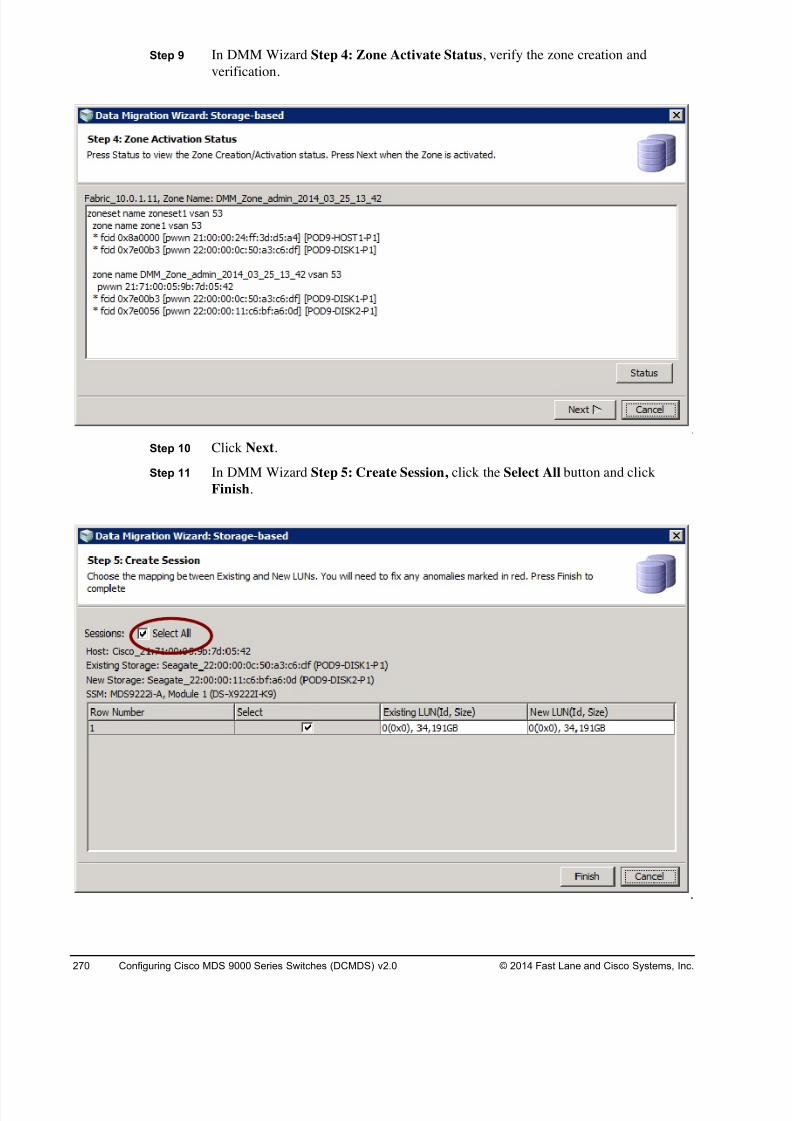
8/18/2019 FL_DCMDS_2.0.3_LG(1).pdf
http://slidepdf.com/reader/full/fldcmds203lg1pdf 270/482
270 Configuring Cisco MDS 9000 Series Switches (DCMDS) v2.0 © 2014 Fast Lane and Cisco Systems, Inc.
Step 9 In DMM Wizard Step 4: Zone Activate Status, verify the zone creation and
verification.
Step 10 Click Next.
Step 11 In DMM Wizard Step 5: Create Session, click the Select All button and click
Finish.
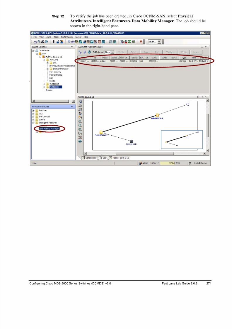
8/18/2019 FL_DCMDS_2.0.3_LG(1).pdf
http://slidepdf.com/reader/full/fldcmds203lg1pdf 271/482
Configuring Cisco MDS 9000 Series Switches (DCMDS) v2.0 Fast Lane Lab Guide 2.0.3 271
Step 12 To verify the job has been created, in Cisco DCNM-SAN, select Physical
Attributes > Intelligent Features > Data Mobility Manager. The job should be
shown in the right-hand pane.
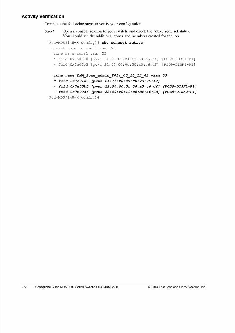
8/18/2019 FL_DCMDS_2.0.3_LG(1).pdf
http://slidepdf.com/reader/full/fldcmds203lg1pdf 272/482
272 Configuring Cisco MDS 9000 Series Switches (DCMDS) v2.0 © 2014 Fast Lane and Cisco Systems, Inc.
Activity Verification
Complete the following steps to verify your configuration.
Step 1 Open a console session to your switch, and check the active zone set status.
You should see the additional zones and members created for the job.
Pod-MDS9148-X(config)# sho zoneset active
zoneset name zoneset1 vsan 53
zone name zone1 vsan 53
* fcid 0x8a0000 [pwwn 21:00:00:24:ff:3d:d5:a4] [POD9-HOST1-P1]
* fcid 0x7e00b3 [pwwn 22:00:00:0c:50:a3:c6:df] [POD9-DISK1-P1]
zone name DMM_Zone_admin_2014_03_25_13_42 vsan 53
* fcid 0x7e0100 [pwwn 21:71:00:05:9b:7d:05:42]
* fcid 0x7e00b3 [pwwn 22:00:00:0c:50:a3:c6:df] [POD9-DISK1-P1]
* fcid 0x7e0056 [pwwn 22:00:00:11:c6:bf:a6:0d] [POD9-DISK2-P1]
Pod-MDS9148-X(config)#
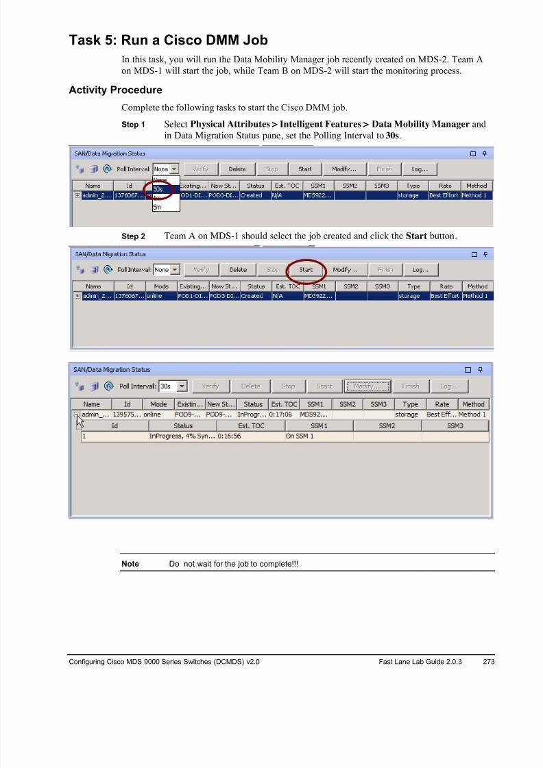
8/18/2019 FL_DCMDS_2.0.3_LG(1).pdf
http://slidepdf.com/reader/full/fldcmds203lg1pdf 273/482
Configuring Cisco MDS 9000 Series Switches (DCMDS) v2.0 Fast Lane Lab Guide 2.0.3 273
Task 5: Run a Cisco DMM Job
In this task, you will run the Data Mobility Manager job recently created on MDS-2. Team A
on MDS-1 will start the job, while Team B on MDS-2 will start the monitoring process.
Activity Procedure
Complete the following tasks to start the Cisco DMM job.
Step 1 Select Physical Attributes > Intelligent Features > Data Mobility Manager and
in Data Migration Status pane, set the Polling Interval to 30s.
Step 2 Team A on MDS-1 should select the job created and click the Start button.
Note Do not wait for the job to complete!!!
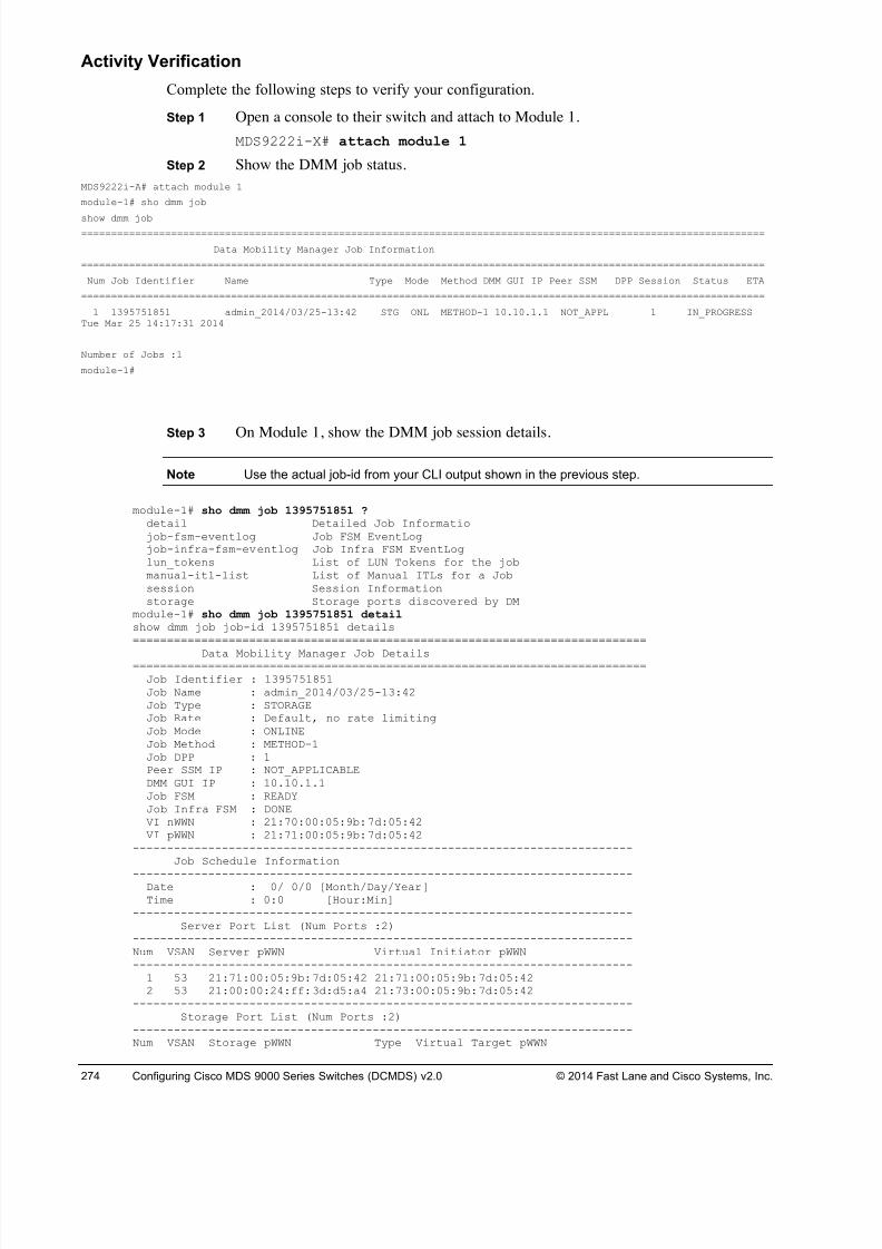
8/18/2019 FL_DCMDS_2.0.3_LG(1).pdf
http://slidepdf.com/reader/full/fldcmds203lg1pdf 274/482
274 Configuring Cisco MDS 9000 Series Switches (DCMDS) v2.0 © 2014 Fast Lane and Cisco Systems, Inc.
Activity Verification
Complete the following steps to verify your configuration.
Step 1 Open a console to their switch and attach to Module 1.
MDS9222i-X# attach module 1
Step 2 Show the DMM job status.
MDS9222i-A# attach module 1
module-1# sho dmm job
show dmm job==================================================================================================================
Data Mobility Manager Job Information
==================================================================================================================
Num Job Identifier Name Type Mode Method DMM GUI IP Peer SSM DPP Session Status ETA
==================================================================================================================
1 1395751851 admin_2014/03/25-13:42 STG ONL METHOD-1 10.10.1.1 NOT_APPL 1 IN_PROGRESSTue Mar 25 14:17:31 2014
Number of Jobs :1
module-1#
Step 3 On Module 1, show the DMM job session details.
Note Use the actual job-id from your CLI output shown in the previous step.
module-1# sho dmm job 1395751851 ? detail Detailed Job Informatiojob-fsm-eventlog Job FSM EventLogjob-infra-fsm-eventlog Job Infra FSM EventLoglun_tokens List of LUN Tokens for the jobmanual-itl-list List of Manual ITLs for a Jobsession Session Informationstorage Storage ports discovered by DM
module-1# sho dmm job 1395751851 detail show dmm job job-id 1395751851 details===========================================================================
Data Mobility Manager Job Details===========================================================================Job Identifier : 1395751851Job Name : admin_2014/03/25-13:42Job Type : STORAGEJob Rate : Default, no rate limitingJob Mode : ONLINEJob Method : METHOD-1Job DPP : 1Peer SSM IP : NOT_APPLICABLEDMM GUI IP : 10.10.1.1Job FSM : READYJob Infra FSM : DONEVI nWWN : 21:70:00:05:9b:7d:05:42VI pWWN : 21:71:00:05:9b:7d:05:42
-------------------------------------------------------------------------Job Schedule Information
-------------------------------------------------------------------------Date : 0/ 0/0 [Month/Day/Year]Time : 0:0 [Hour:Min]
-------------------------------------------------------------------------Server Port List (Num Ports :2)
-------------------------------------------------------------------------Num VSAN Server pWWN Virtual Initiator pWWN-------------------------------------------------------------------------
1 53 21:71:00:05:9b:7d:05:42 21:71:00:05:9b:7d:05:422 53 21:00:00:24:ff:3d:d5:a4 21:73:00:05:9b:7d:05:42
-------------------------------------------------------------------------Storage Port List (Num Ports :2)
-------------------------------------------------------------------------Num VSAN Storage pWWN Type Virtual Target pWWN
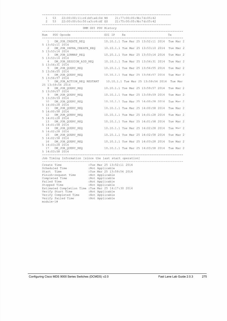
8/18/2019 FL_DCMDS_2.0.3_LG(1).pdf
http://slidepdf.com/reader/full/fldcmds203lg1pdf 275/482
Configuring Cisco MDS 9000 Series Switches (DCMDS) v2.0 Fast Lane Lab Guide 2.0.3 275
-------------------------------------------------------------------------1 53 22:00:00:11:c6:bf:a6:0d NS 21:77:00:05:9b:7d:05:422 53 22:00:00:0c:50:a3:c6:df ES 21:75:00:05:9b:7d:05:42
-------------------------------------------------------------------------DMM GUI PDU History
--------------------------------------------------------------------------------Num PDU Opcode GUI IP Rx Tx--------------------------------------------------------------------------------
1 DM_JOB_CREATE_REQ 10.10.1.1 Tue Mar 25 13:52:11 2014 Tue Mar 25 13:52:11 2014
2 DM_JOB_INFRA_CREATE_REQ 10.10.1.1 Tue Mar 25 13:53:10 2014 Tue Mar 25 13:53:14 2014
3 DM_JOB_LUNMAP_REQ 10.10.1.1 Tue Mar 25 13:53:14 2014 Tue Mar 25 13:53:14 20144 DM_JOB_SESSION_ADD_REQ 10.10.1.1 Tue Mar 25 13:56:31 2014 Tue Mar 2
5 13:56:31 20145 DM_JOB_QUERY_REQ 10.10.1.1 Tue Mar 25 13:56:55 2014 Tue Mar 2
5 13:56:55 20146 DM_JOB_QUERY_REQ 10.10.1.1 Tue Mar 25 13:56:57 2014 Tue Mar 2
5 13:56:57 20147 DM_JOB_ACTION_REQ RESTART 10.10.1.1 Tue Mar 25 13:59:54 2014 Tue Mar
25 13:59:54 20148 DM_JOB_QUERY_REQ 10.10.1.1 Tue Mar 25 13:59:57 2014 Tue Mar 2
5 13:59:57 20149 DM_JOB_QUERY_REQ 10.10.1.1 Tue Mar 25 13:59:59 2014 Tue Mar 2
5 13:59:59 201410 DM_JOB_QUERY_REQ 10.10.1.1 Tue Mar 25 14:00:28 2014 Tue Mar 2
5 14:00:28 201411 DM_JOB_QUERY_REQ 10.10.1.1 Tue Mar 25 14:00:58 2014 Tue Mar 2
5 14:00:58 201412 DM_JOB_QUERY_REQ 10.10.1.1 Tue Mar 25 14:01:28 2014 Tue Mar 25 14:01:28 2014
13 DM_JOB_QUERY_REQ 10.10.1.1 Tue Mar 25 14:01:58 2014 Tue Mar 25 14:01:58 2014
14 DM_JOB_QUERY_REQ 10.10.1.1 Tue Mar 25 14:02:28 2014 Tue Mar 25 14:02:28 2014
15 DM_JOB_QUERY_REQ 10.10.1.1 Tue Mar 25 14:02:58 2014 Tue Mar 25 14:02:58 2014
16 DM_JOB_QUERY_REQ 10.10.1.1 Tue Mar 25 14:03:28 2014 Tue Mar 25 14:03:28 2014
17 DM_JOB_QUERY_REQ 10.10.1.1 Tue Mar 25 14:03:58 2014 Tue Mar 25 14:03:58 2014--------------------------------------------------------------------------------Job Timing Information [since the last start operation]--------------------------------------------------------------------------------Create Time :Tue Mar 25 13:52:11 2014
Scheduled Time :Not ApplicableStart Time :Tue Mar 25 13:59:54 2014Finish-request Time :Not ApplicableCompleted Time :Not ApplicableFailed Time :Not ApplicableStopped Time :Not ApplicableEstimated Completion Time :Tue Mar 25 14:17:30 2014Verify Start Time :Not ApplicableVerify Completed Time :Not ApplicableVerify Failed Time :Not Applicablemodule-1#
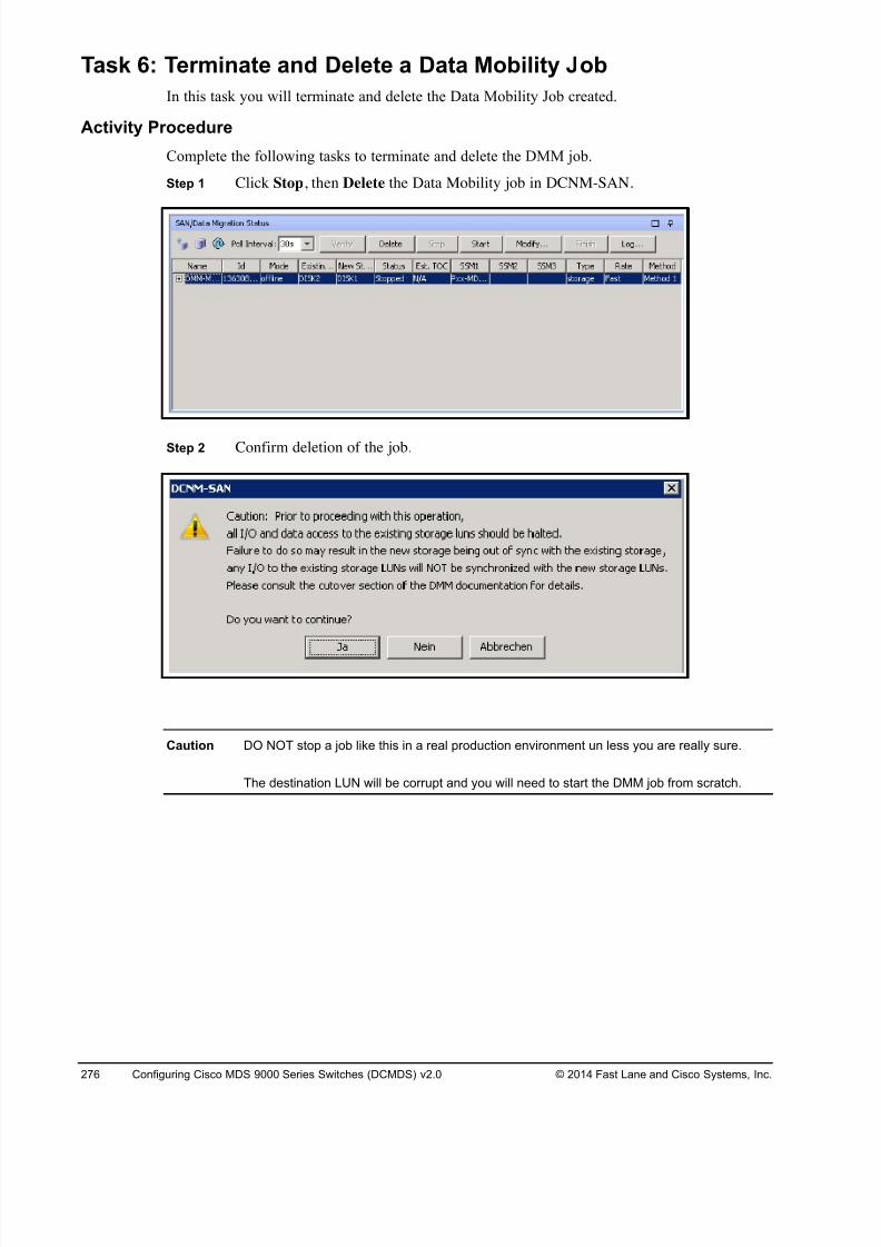
8/18/2019 FL_DCMDS_2.0.3_LG(1).pdf
http://slidepdf.com/reader/full/fldcmds203lg1pdf 276/482
276 Configuring Cisco MDS 9000 Series Switches (DCMDS) v2.0 © 2014 Fast Lane and Cisco Systems, Inc.
Task 6: Terminate and Delete a Data Mobility Job
In this task you will terminate and delete the Data Mobility Job created.
Activity Procedure
Complete the following tasks to terminate and delete the DMM job.
Step 1 Click Stop, then Delete the Data Mobility job in DCNM-SAN.
Step 2 Confirm deletion of the job.
Caution DO NOT stop a job like this in a real production environment un less you are really sure.
The destination LUN will be corrupt and you will need to start the DMM job from scratch.
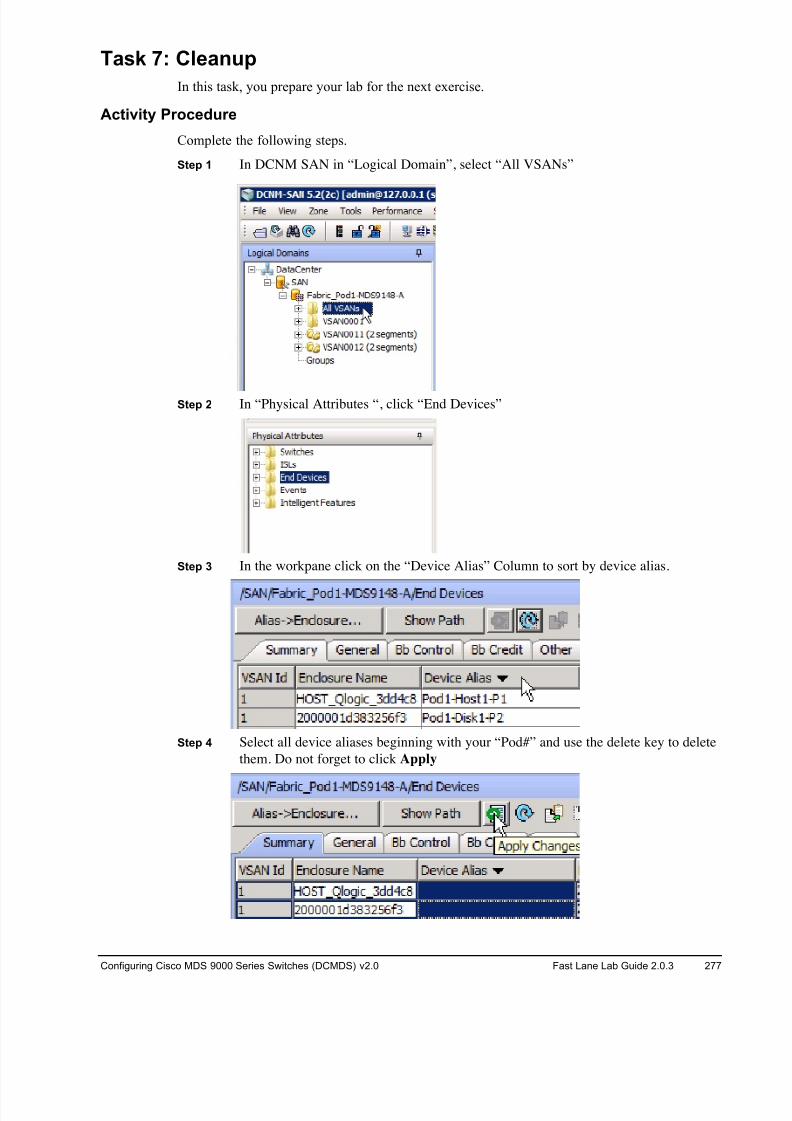
8/18/2019 FL_DCMDS_2.0.3_LG(1).pdf
http://slidepdf.com/reader/full/fldcmds203lg1pdf 277/482
Configuring Cisco MDS 9000 Series Switches (DCMDS) v2.0 Fast Lane Lab Guide 2.0.3 277
Task 7: Cleanup
In this task, you prepare your lab for the next exercise.
Activity Procedure
Complete the following steps.
Step 1 In DCNM SAN in “Logical Domain”, select “All VSANs”
Step 2 In “Physical Attributes “, click “End Devices”
Step 3 In the workpane click on the “Device Alias” Column to sort by device alias.
Step 4 Select all device aliases beginning with your “Pod#” and use the delete key to delete
them. Do not forget to click Apply
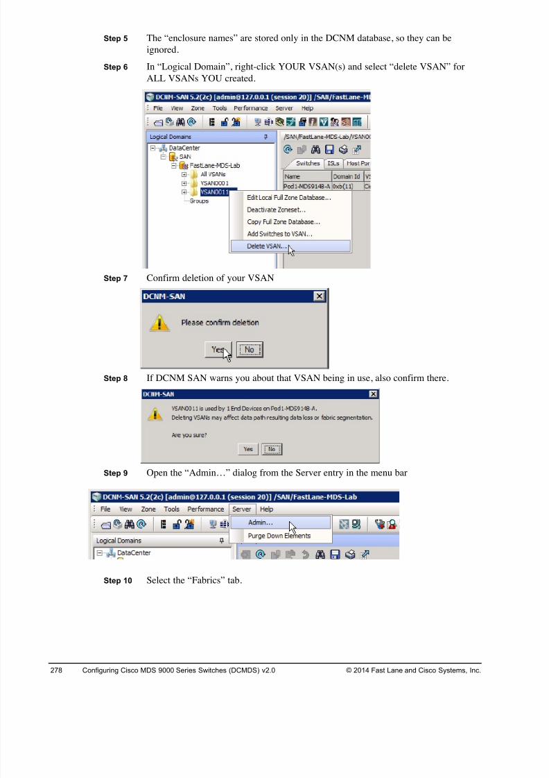
8/18/2019 FL_DCMDS_2.0.3_LG(1).pdf
http://slidepdf.com/reader/full/fldcmds203lg1pdf 278/482
278 Configuring Cisco MDS 9000 Series Switches (DCMDS) v2.0 © 2014 Fast Lane and Cisco Systems, Inc.
Step 5 The “enclosure names” are stored only in the DCNM database, so they can be
ignored.
Step 6 In “Logical Domain”, right-click YOUR VSAN(s) and select “delete VSAN” for
ALL VSANs YOU created.
Step 7 Confirm deletion of your VSAN
Step 8 If DCNM SAN warns you about that VSAN being in use, also confirm there.
Step 9 Open the “Admin…” dialog from the Server entry in the menu bar
Step 10 Select the “Fabrics” tab.
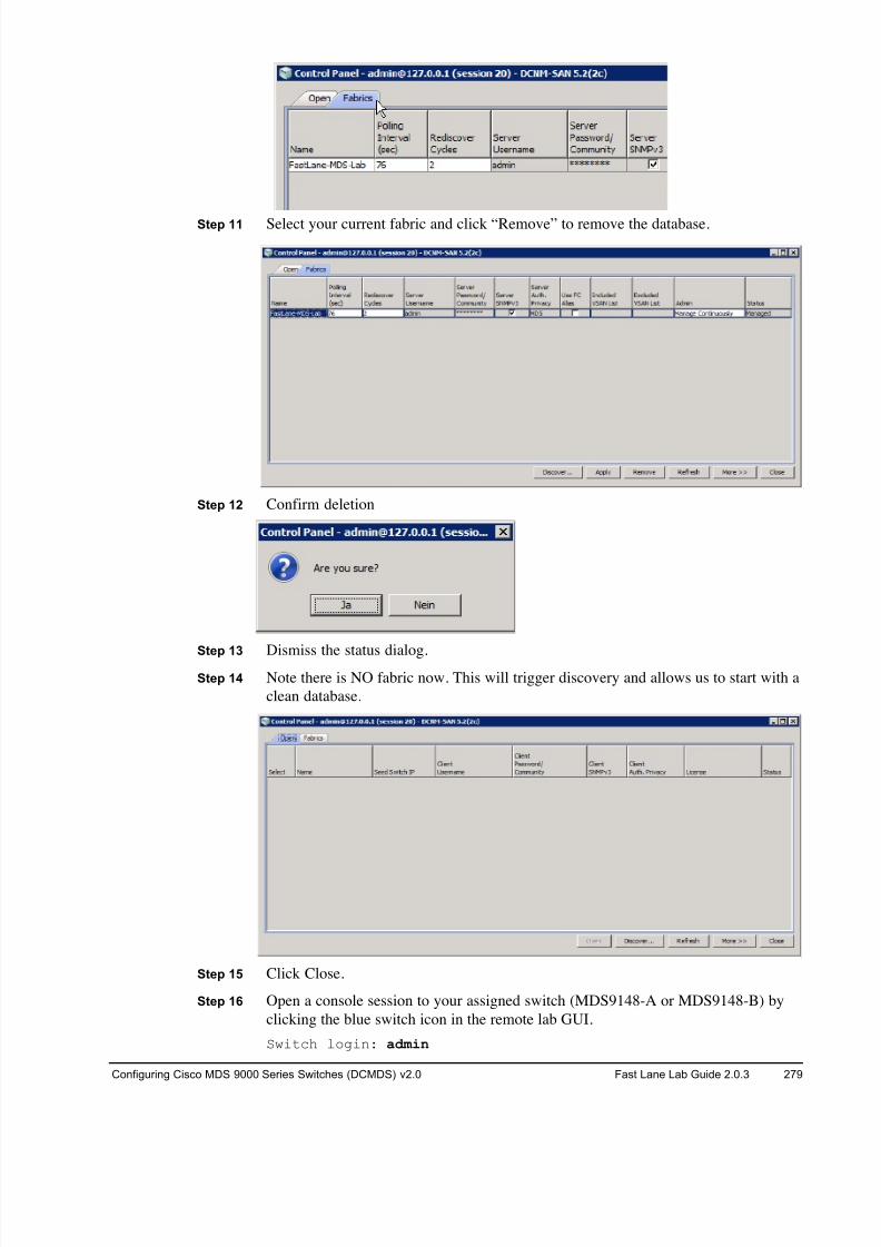
8/18/2019 FL_DCMDS_2.0.3_LG(1).pdf
http://slidepdf.com/reader/full/fldcmds203lg1pdf 279/482
Configuring Cisco MDS 9000 Series Switches (DCMDS) v2.0 Fast Lane Lab Guide 2.0.3 279
Step 11 Select your current fabric and click “Remove” to remove the database.
Step 12 Confirm deletion
Step 13 Dismiss the status dialog.Step 14 Note there is NO fabric now. This will trigger discovery and allows us to start with a
clean database.
Step 15 Click Close.
Step 16 Open a console session to your assigned switch (MDS9148-A or MDS9148-B) by
clicking the blue switch icon in the remote lab GUI.
Switch login: admin
8/18/2019 FL_DCMDS_2.0.3_LG(1).pdf
http://slidepdf.com/reader/full/fldcmds203lg1pdf 280/482
280 Configuring Cisco MDS 9000 Series Switches (DCMDS) v2.0 © 2014 Fast Lane and Cisco Systems, Inc.
Password: 1234QWer
Step 17 Clear the current startup configuration ON YOUR 9148s ONLY, DO NOT CLEAR
THE CORE 9222is!!! .
# write erase
The following message is displayed:
Warning: This command will erase the startup-configuration.
Do you wish to proceed anyway? [y/n] [N]
Type y to proceed.
Step 18 Reboot the 9148 switch.
# reload
This command will reboot the system. (y/n)?
Type y to proceed.
Step 19 The LAST team completing needs to disable DMM (later we will need the processor
compex for FCIP)
MDS9222i# no smm enable feature dmm module 1
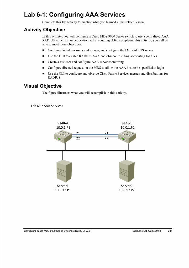
8/18/2019 FL_DCMDS_2.0.3_LG(1).pdf
http://slidepdf.com/reader/full/fldcmds203lg1pdf 281/482
Configuring Cisco MDS 9000 Series Switches (DCMDS) v2.0 Fast Lane Lab Guide 2.0.3 281
Lab 6-1: Configuring AAA Services Complete this lab activity to practice what you learned in the related lesson.
Activity Objective
In this activity, you will configure a Cisco MDS 9000 Series switch to use a centralized AAA
RADIUS server for authentication and accounting. After completing this activity, you will be
able to meet these objectives:
! Configure Windows users and groups, and configure the IAS RADIUS server
! Use the GUI to enable RADIUS AAA and observe resulting accounting log files
! Create a test user and configure AAA server monitoring
! Configure directed request on the MDS to allow the AAA host to be specified at login
! Use the CLI to configure and observe Cisco Fabric Services merges and distributions for
RADIUS
Visual Objective
The figure illustrates what you will accomplish in this activity.
!"# %&'( ))) *+,-./+0
1'
11
1'
11
2'34&5(
'6767'781
2'34&)(
'6767'78'
*+,-+,'
'6767'7'8'
*+,-+,1
'6767'7'81
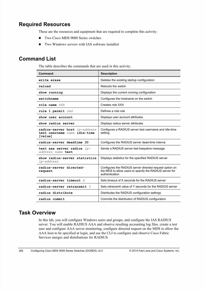
8/18/2019 FL_DCMDS_2.0.3_LG(1).pdf
http://slidepdf.com/reader/full/fldcmds203lg1pdf 282/482
282 Configuring Cisco MDS 9000 Series Switches (DCMDS) v2.0 © 2014 Fast Lane and Cisco Systems, Inc.
Required Resources
These are the resources and equipment that are required to complete this activity:
! Two Cisco MDS 9000 Series switches
! Two Windows servers with IAS software installed
Command List
The table describes the commands that are used in this activity.
Command Description
write erase Deletes the existing startup configuration
reload Reboots the switch
show running Displays the current running configuration
switchname Configures the hostname on the switch
role name XXX Creates role XXX
rule 1 permit cmd Defines a role rule
show user account Displays user account attributes
show radius server Displays radius server attributes
radius-server host ip-address test username name idle-time[value]
Configures a RADIUS server test username and idle-timesetting
radius-server deadtime 30 Configures the RADIUS server dead-time interval
test aaa server radius ip-
address name test
Sends a RADIUS server test keepalive message
show radius-server statisticsip-address
Displays statistics for the specified RADIUS server
radius-server directed-request
Configures the RADIUS server directed request option onthe MDS to allow users to specify the RADIUS server forauthentication
radius-server timeout X Sets timeout of X seconds for the RADIUS server
radius-server retransmit Y Sets retransmit value of Y seconds for the RADIUS server
radius distribute Distributes the RADIUS configuration settings
radius commit Commits the distribution of RADIUS configuration
Task Overview
In this lab, you will configure Windows users and groups, and configure the IAS RADIUS
server. You will enable RADIUS AAA and observe resulting accounting log files, create a test
user and configure AAA server monitoring, configure directed request on the MDS to allow the
AAA host to be specified at login, and use the CLI to configure and observe Cisco Fabric
Services merges and distributions for RADIUS.

8/18/2019 FL_DCMDS_2.0.3_LG(1).pdf
http://slidepdf.com/reader/full/fldcmds203lg1pdf 283/482
Configuring Cisco MDS 9000 Series Switches (DCMDS) v2.0 Fast Lane Lab Guide 2.0.3 283
Task 1: Complete the Initial Switch Configuration
In this task, you complete the initial switch configuration process.
Note If you are working in teams within a pod, one student will configure Fabric A / MDS9148-A
and the other student will configure Fabric B / MDS9148-B. If you are working alone, you
will need to configure both switches/fabrics!
Activity ProcedureComplete the following steps on both MDS switches:
Step 1 Open a console session to your assigned switch (MDS9148-A or MDS9148-B) by
clicking the blue switch icon in the remote lab GUI.
Note If the switch asks for username and password at this step log in with user “admin” and
password “1234QWer”, erase the configuration and reboot.
Step 2 After the switch reboots, it will automatically launch the setup process. Answer the
questions according to the following example, replacing your pod number and
switch ID where appropriate.
---- System Admin Account Setup ----
Do you want to enforce secure password standard (yes/no) [y]: y
Enter the password for "admin": 1234QWer < note QW is UPPERCASE
Confirm the password for "admin": 1234QWer
Caution DO NOT USE ANY OTHER PASSWORD. This may force the lab support management
software to recover passwords and your configuration may be deleted.
--- Basic System Configuration Dialog ---This setup utility will guide you through the basic configuration ofthe system. Setup configures only enough connectivity for managementof the system.
Please register Cisco MDS 9000 Family devices promptly with yoursupplier. Failure to register may affect response times for initialservice calls. MDS devices must be registered to receive entitledsupport services.
Press Enter at anytime to skip a dialog. Use ctrl-c at anytime to skipthe remaining dialogs.
Would you like to enter the basic configuration dialog (yes/no): y
Create another login account (yes/no) [n]: <Enter>
Configure read-only SNMP community string (yes/no) [n]: <Enter> Configure read-write SNMP community string (yes/no) [n]: <Enter>
Enter the switch name: Pod#-MDS9148-Y (where # is your pod number and Y is the
switch ID; for example: POD#-MDS9148-A)
Continue with Out-of-band (mgmt0) management configuration? (yes/no)[y]: <Enter>
Mgmt0 IPv4 address : <10.0.1.PN >
(where P is your Pod# and N is 1 for MDS9148-A and 2 for MDS9148-B)
Mgmt0 IPv4 netmask : 255.255.255.0

8/18/2019 FL_DCMDS_2.0.3_LG(1).pdf
http://slidepdf.com/reader/full/fldcmds203lg1pdf 284/482
284 Configuring Cisco MDS 9000 Series Switches (DCMDS) v2.0 © 2014 Fast Lane and Cisco Systems, Inc.
Configure the default gateway? (yes/no) [y]: <No>
Configure advanced IP options? (yes/no) [n]: <Enter>
Enable the ssh service? (yes/no) [y]: <No>
Enable the telnet service? (yes/no) [n]: <Yes>
Configure congestion/no_credit drop for fc interfaces? (yes/no)[y]: <Enter>
Enter the type of drop to configure congestion/no_credit drop?
(con/no) [c]: <Enter>Enter milliseconds in multiple of 10 for congestion-drop in range [100- 500], or [d/default] for default: <d>
Enter mode for congestion/no_credit drop[E/F]: <Enter>
Enable the http-server? (yes/no) [y]: <Enter>
Configure clock? (yes/no) [n]: <Enter>
Configure timezone? (yes/no) [n]: <Enter>
Configure summertime? (yes/no) [n]: <Enter>
Configure the ntp server? (yes/no) [n]: <Enter>
Configure default switchport interface state (shut/noshut) [shut]: <Enter>
Configure default switchport trunk mode (on/off/auto) [on]: <Enter> Configure default switchport port mode F (yes/no) [n]: <Enter>
Configure default zone policy (permit/deny) [deny]: <Enter>
Enable full zoneset distribution (yes/no) [n]: <Enter>
Configure default zone mode (basic/enhanced) [basic]: <Enter>
Step 3 A summary of the configuration will be displayed:
The following configuration will be applied:
password strength-check
switchname POD#-MDS9148-A
interface mgmt0
ip address 10.0.1.PN 255.255.255.0
no shutdown
no feature ssh
feature telnet
feature http-server
system default switchport shutdown
system default switchport trunk mode on
no system default zone default-zone permit
no system default zone distribute full
no system default zone mode enhanced
Step 4 Press Enter twice to save the configuration.
Would you like to edit the configuration? (yes/no) [n]: <Enter>
Use this configuration and save it? (yes/no) [y]: <Enter>
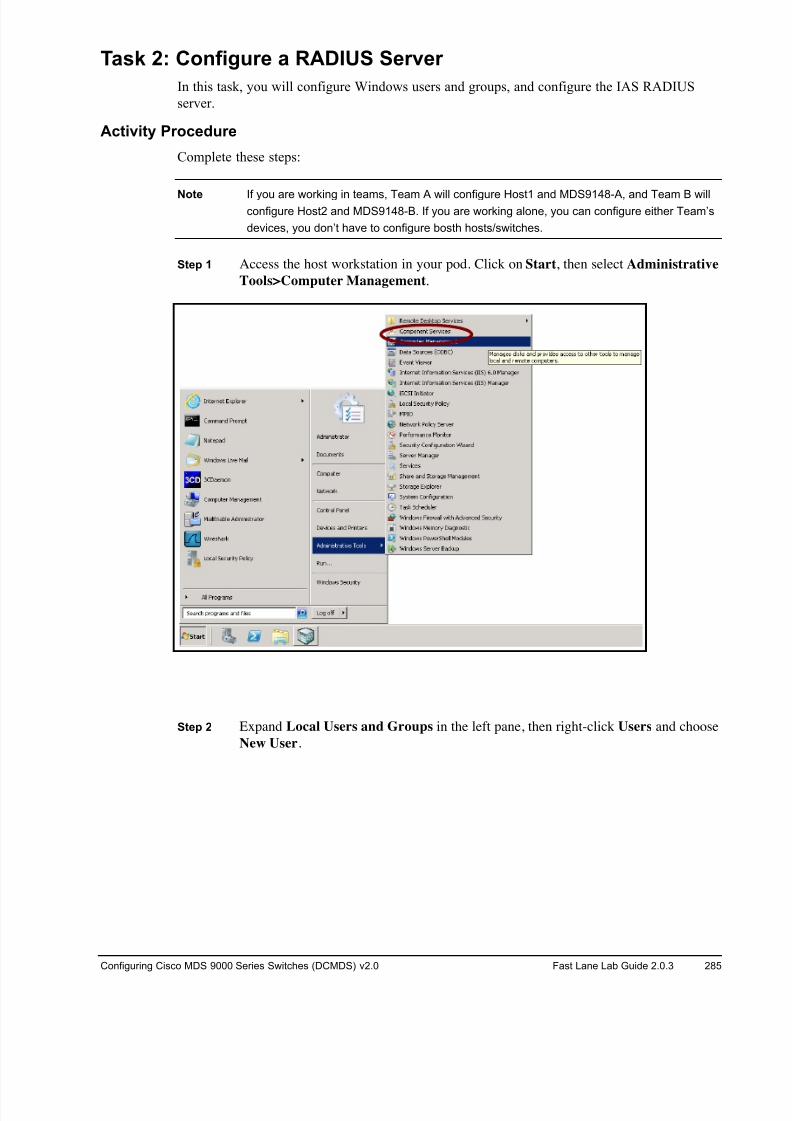
8/18/2019 FL_DCMDS_2.0.3_LG(1).pdf
http://slidepdf.com/reader/full/fldcmds203lg1pdf 285/482
Configuring Cisco MDS 9000 Series Switches (DCMDS) v2.0 Fast Lane Lab Guide 2.0.3 285
Task 2: Configure a RADIUS Server
In this task, you will configure Windows users and groups, and configure the IAS RADIUS
server.
Activity Procedure
Complete these steps:
Note If you are working in teams, Team A will configure Host1 and MDS9148-A, and Team B willconfigure Host2 and MDS9148-B. If you are working alone, you can configure either Team’s
devices, you don’t have to configure bosth hosts/switches.
Step 1 Access the host workstation in your pod. Click on Start, then select Administrative
Tools>Computer Management.
Step 2 Expand Local Users and Groups in the left pane, then right-click Users and choose
New User.
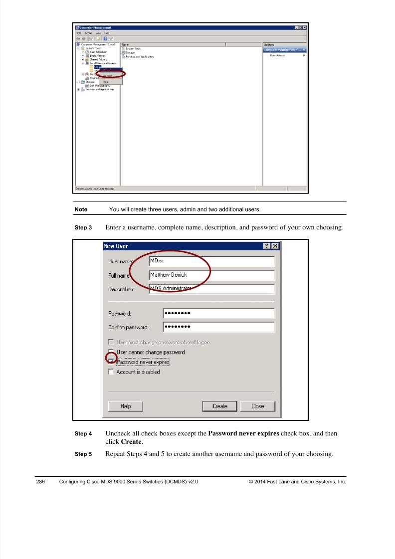
8/18/2019 FL_DCMDS_2.0.3_LG(1).pdf
http://slidepdf.com/reader/full/fldcmds203lg1pdf 286/482
286 Configuring Cisco MDS 9000 Series Switches (DCMDS) v2.0 © 2014 Fast Lane and Cisco Systems, Inc.
Note You will create three users, admin and two additional users.
Step 3 Enter a username, complete name, description, and password of your own choosing.
Step 4 Uncheck all check boxes except the Password never expires check box, and then
click Create.
Step 5 Repeat Steps 4 and 5 to create another username and password of your choosing.
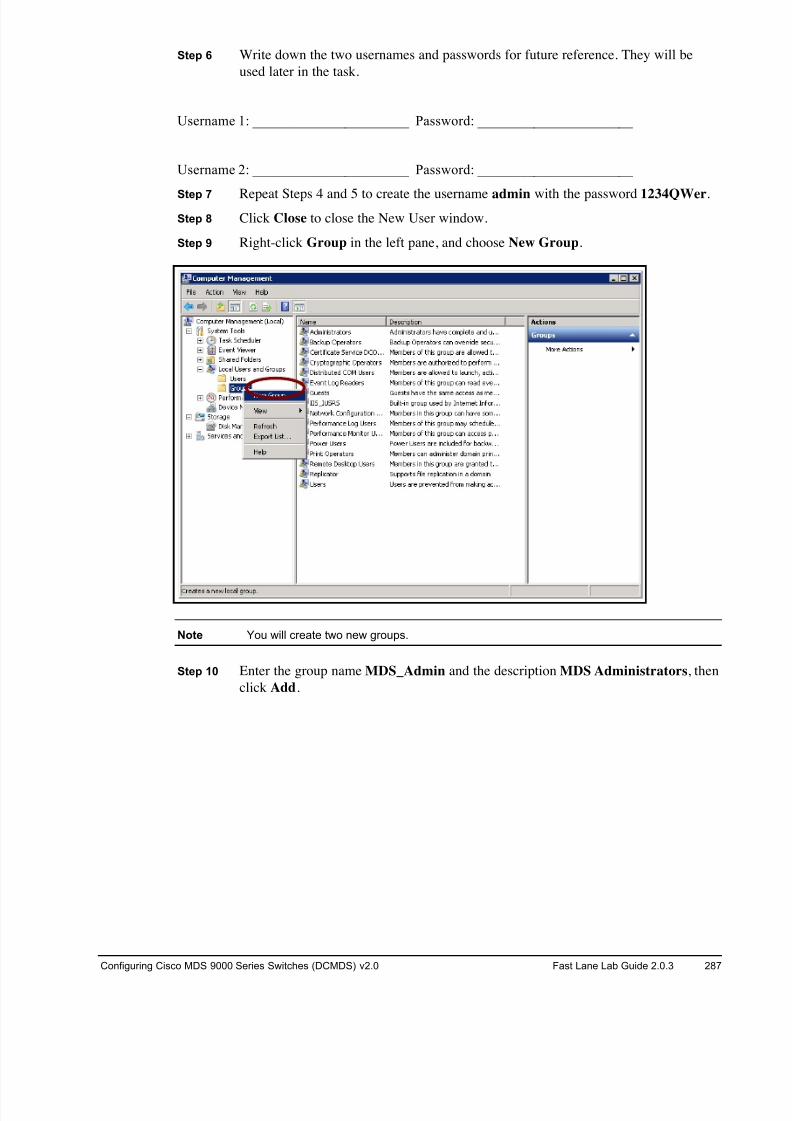
8/18/2019 FL_DCMDS_2.0.3_LG(1).pdf
http://slidepdf.com/reader/full/fldcmds203lg1pdf 287/482
Configuring Cisco MDS 9000 Series Switches (DCMDS) v2.0 Fast Lane Lab Guide 2.0.3 287
Step 6 Write down the two usernames and passwords for future reference. They will be
used later in the task.
Username 1: ______________________ Password: ______________________
Username 2: ______________________ Password: ______________________
Step 7 Repeat Steps 4 and 5 to create the username admin with the password 1234QWer.
Step 8 Click Close to close the New User window.
Step 9 Right-click Group in the left pane, and choose New Group.
Note You will create two new groups.
Step 10 Enter the group name MDS_Admin and the description MDS Administrators, then
click Add.
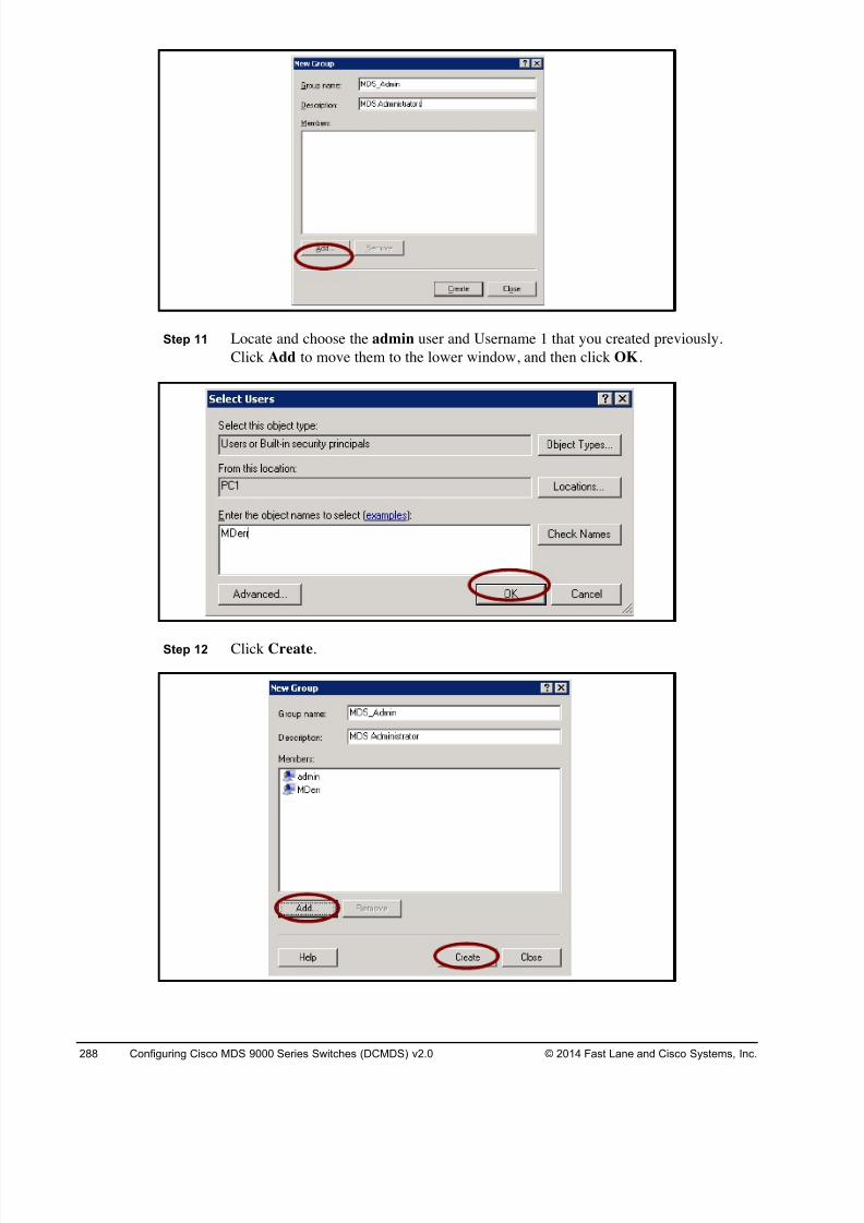
8/18/2019 FL_DCMDS_2.0.3_LG(1).pdf
http://slidepdf.com/reader/full/fldcmds203lg1pdf 288/482
288 Configuring Cisco MDS 9000 Series Switches (DCMDS) v2.0 © 2014 Fast Lane and Cisco Systems, Inc.
Step 11 Locate and choose the admin user and Username 1 that you created previously.
Click Add to move them to the lower window, and then click OK.
Step 12 Click Create.
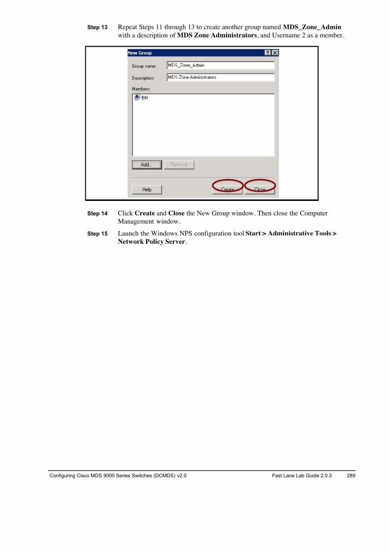
8/18/2019 FL_DCMDS_2.0.3_LG(1).pdf
http://slidepdf.com/reader/full/fldcmds203lg1pdf 289/482
Configuring Cisco MDS 9000 Series Switches (DCMDS) v2.0 Fast Lane Lab Guide 2.0.3 289
Step 13 Repeat Steps 11 through 13 to create another group named MDS_Zone_Admin
with a description of MDS Zone Administrators, and Username 2 as a member.
Step 14 Click Create and Close the New Group window. Then close the Computer
Management window.
Step 15 Launch the Windows NPS configuration tool Start > Administrative Tools >
Network Policy Server.
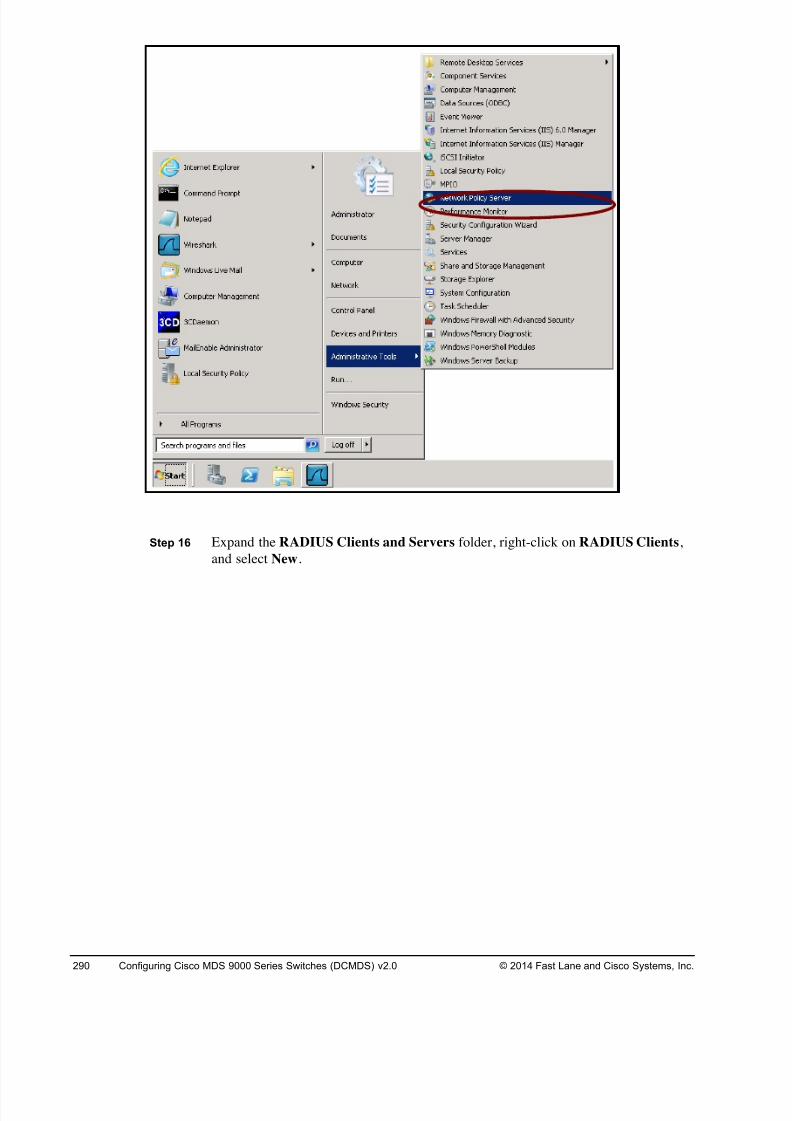
8/18/2019 FL_DCMDS_2.0.3_LG(1).pdf
http://slidepdf.com/reader/full/fldcmds203lg1pdf 290/482
290 Configuring Cisco MDS 9000 Series Switches (DCMDS) v2.0 © 2014 Fast Lane and Cisco Systems, Inc.
Step 16 Expand the RADIUS Clients and Servers folder, right-click on RADIUS Clients,
and select New.
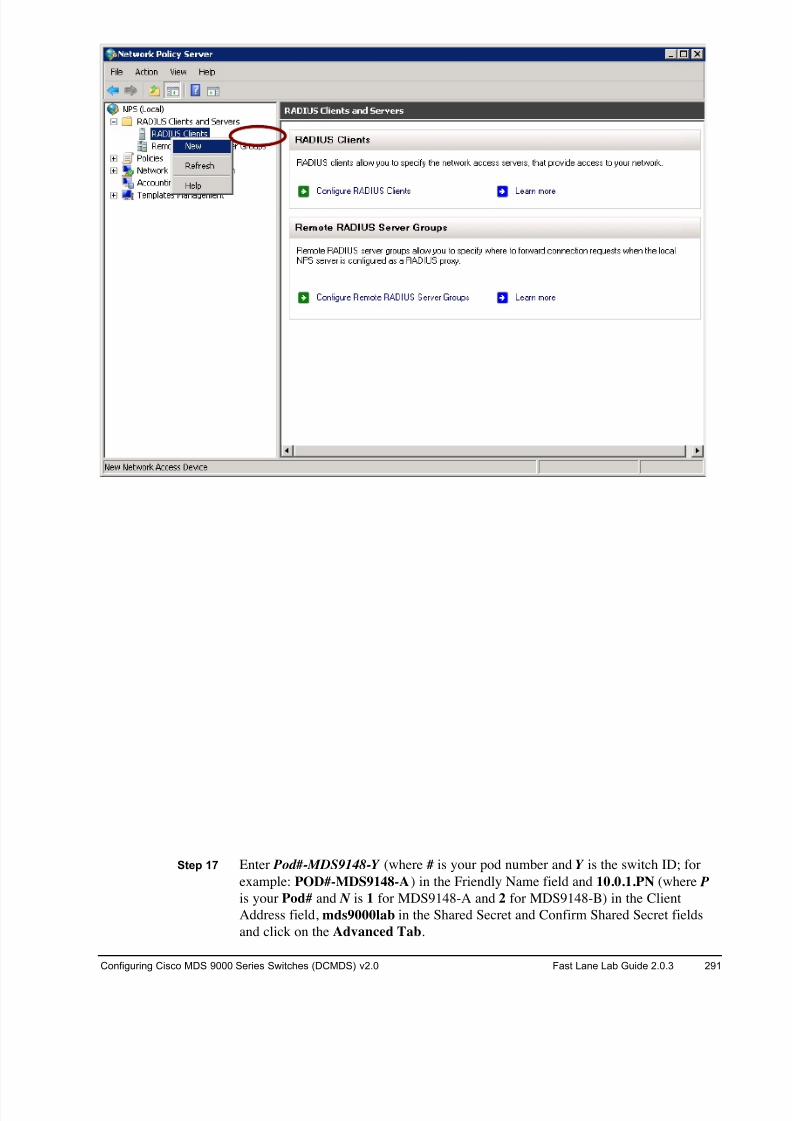
8/18/2019 FL_DCMDS_2.0.3_LG(1).pdf
http://slidepdf.com/reader/full/fldcmds203lg1pdf 291/482
Configuring Cisco MDS 9000 Series Switches (DCMDS) v2.0 Fast Lane Lab Guide 2.0.3 291
Step 17 Enter Pod#-MDS9148-Y (where # is your pod number and Y is the switch ID; for
example: POD#-MDS9148-A) in the Friendly Name field and 10.0.1.PN (where P
is your Pod# and N is 1 for MDS9148-A and 2 for MDS9148-B) in the Client
Address field, mds9000lab in the Shared Secret and Confirm Shared Secret fields
and click on the Advanced Tab.
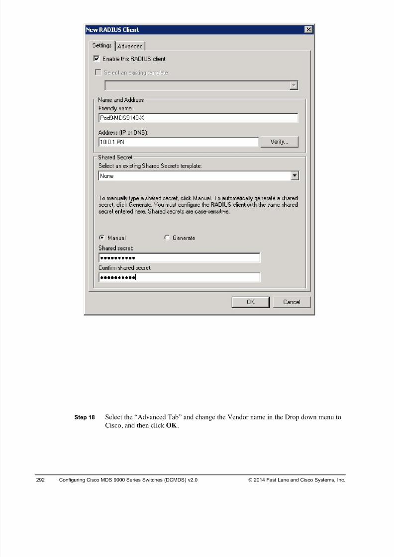
8/18/2019 FL_DCMDS_2.0.3_LG(1).pdf
http://slidepdf.com/reader/full/fldcmds203lg1pdf 292/482
292 Configuring Cisco MDS 9000 Series Switches (DCMDS) v2.0 © 2014 Fast Lane and Cisco Systems, Inc.
Step 18 Select the “Advanced Tab” and change the Vendor name in the Drop down menu to
Cisco, and then click OK.
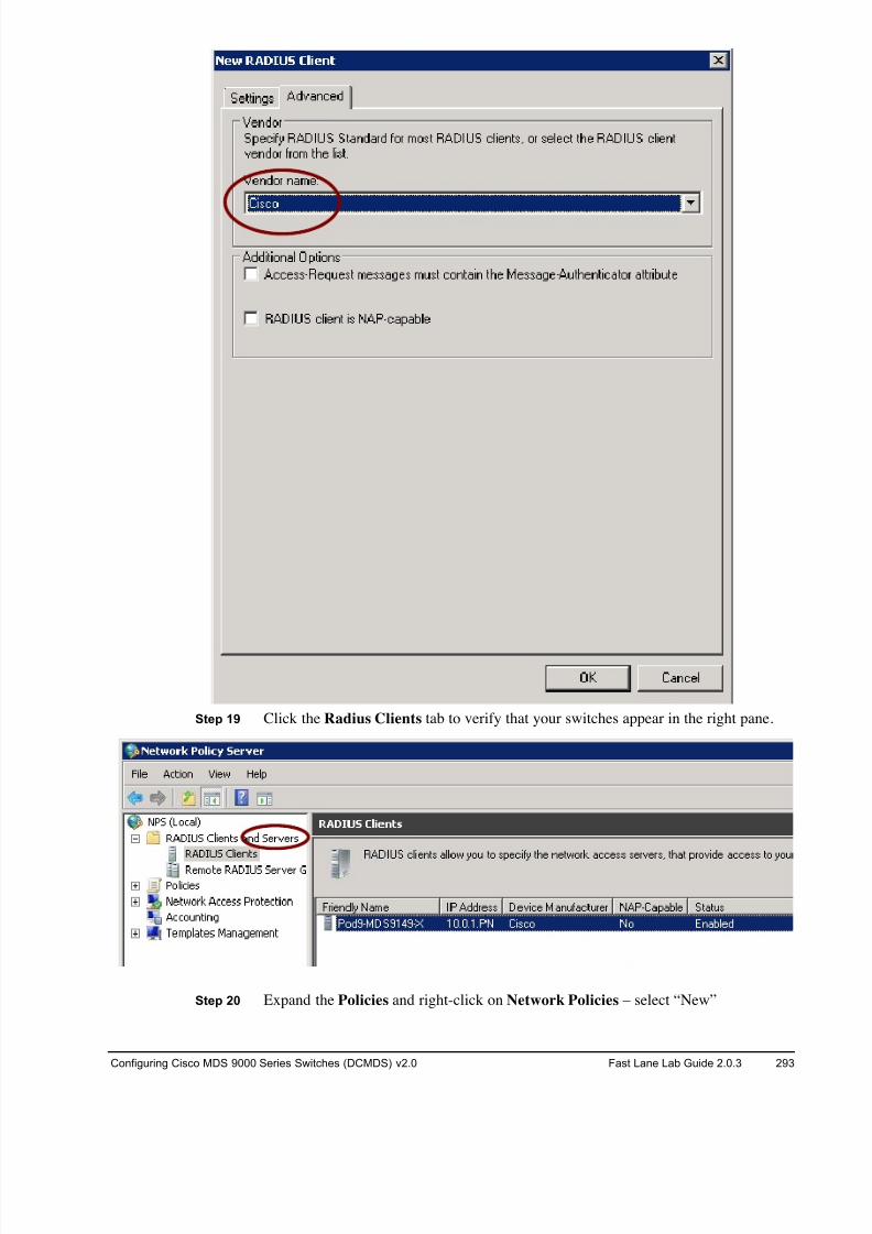
8/18/2019 FL_DCMDS_2.0.3_LG(1).pdf
http://slidepdf.com/reader/full/fldcmds203lg1pdf 293/482
Configuring Cisco MDS 9000 Series Switches (DCMDS) v2.0 Fast Lane Lab Guide 2.0.3 293
Step 19 Click the Radius Clients tab to verify that your switches appear in the right pane.
Step 20 Expand the Policies and right-click on Network Policies – select “New”
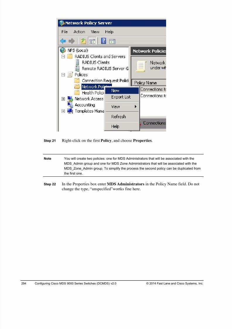
8/18/2019 FL_DCMDS_2.0.3_LG(1).pdf
http://slidepdf.com/reader/full/fldcmds203lg1pdf 294/482
294 Configuring Cisco MDS 9000 Series Switches (DCMDS) v2.0 © 2014 Fast Lane and Cisco Systems, Inc.
Step 21 Right-click on the first Policy, and choose Properties.
Note You will create two policies: one for MDS Administrators that will be associated with the
MDS_Admin group and one for MDS Zone Administrators that will be associated with the
MDS_Zone_Admin group. To simplify the process the second policy can be duplicated from
the first one.
Step 22 In the Properties box enter MDS Administrators in the Policy Name field. Do not
change the type, “unspecified”wortks fine here.
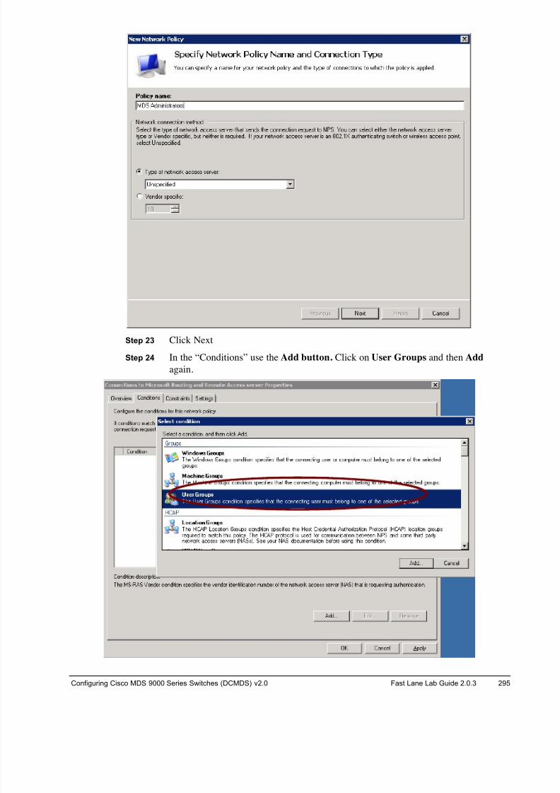
8/18/2019 FL_DCMDS_2.0.3_LG(1).pdf
http://slidepdf.com/reader/full/fldcmds203lg1pdf 295/482
Configuring Cisco MDS 9000 Series Switches (DCMDS) v2.0 Fast Lane Lab Guide 2.0.3 295
Step 23 Click Next
Step 24 In the “Conditions” use the Add button. Click on User Groups and then Add
again.
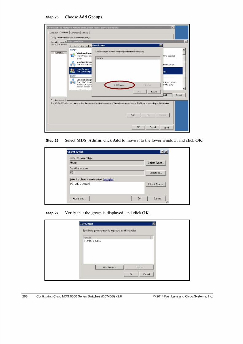
8/18/2019 FL_DCMDS_2.0.3_LG(1).pdf
http://slidepdf.com/reader/full/fldcmds203lg1pdf 296/482
296 Configuring Cisco MDS 9000 Series Switches (DCMDS) v2.0 © 2014 Fast Lane and Cisco Systems, Inc.
Step 25 Choose Add Groups.
Step 26 Select MDS_Admin, click Add to move it to the lower window, and click OK.
Step 27 Verify that the group is displayed, and click OK.
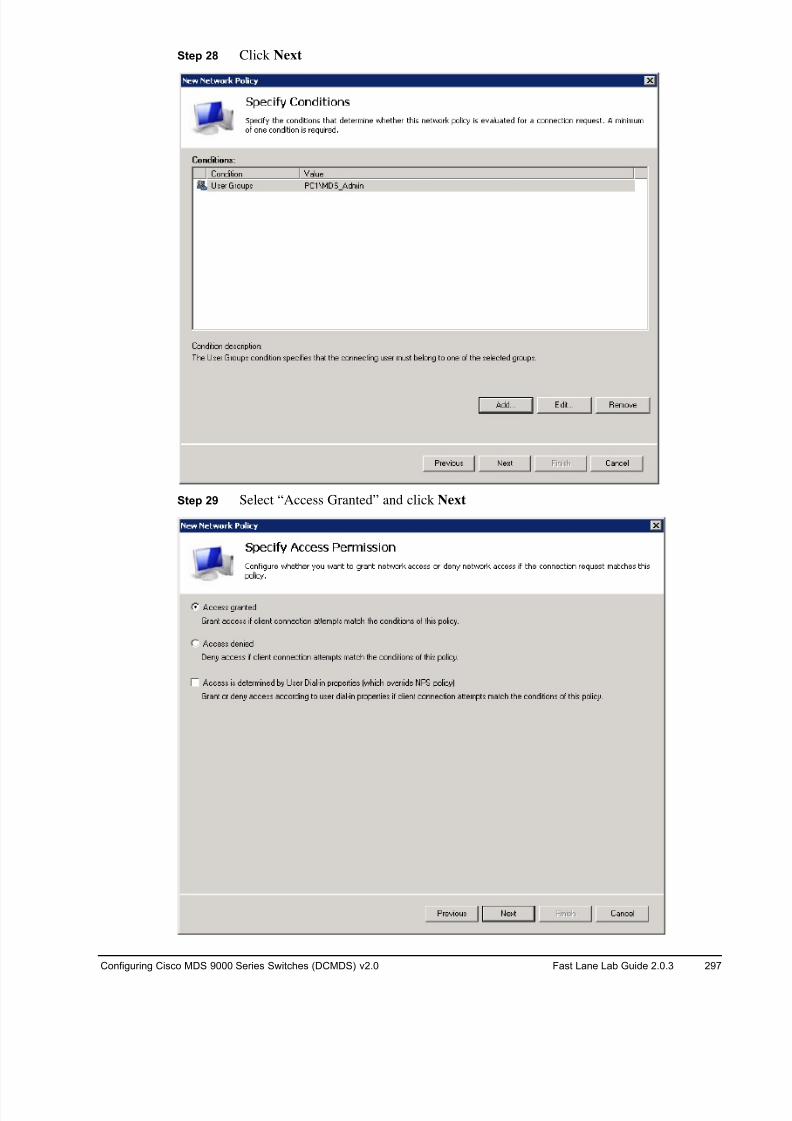
8/18/2019 FL_DCMDS_2.0.3_LG(1).pdf
http://slidepdf.com/reader/full/fldcmds203lg1pdf 297/482
Configuring Cisco MDS 9000 Series Switches (DCMDS) v2.0 Fast Lane Lab Guide 2.0.3 297
Step 28 Click Next
Step 29 Select “Access Granted” and click Next
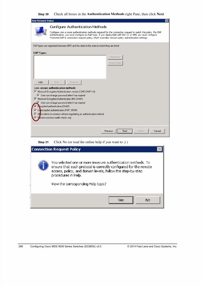
8/18/2019 FL_DCMDS_2.0.3_LG(1).pdf
http://slidepdf.com/reader/full/fldcmds203lg1pdf 298/482
298 Configuring Cisco MDS 9000 Series Switches (DCMDS) v2.0 © 2014 Fast Lane and Cisco Systems, Inc.
Step 30 Check all boxes in the Authentication Methods right Pane, then click Next
Step 31 Click No (or read the online help if you want to ;) )
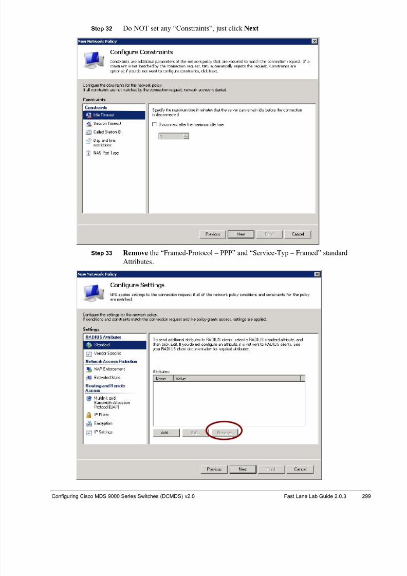
8/18/2019 FL_DCMDS_2.0.3_LG(1).pdf
http://slidepdf.com/reader/full/fldcmds203lg1pdf 299/482
Configuring Cisco MDS 9000 Series Switches (DCMDS) v2.0 Fast Lane Lab Guide 2.0.3 299
Step 32 Do NOT set any “Constraints”, just click Next
Step 33 Remove the “Framed-Protocol – PPP” and “Service-Typ – Framed” standard
Attributes.
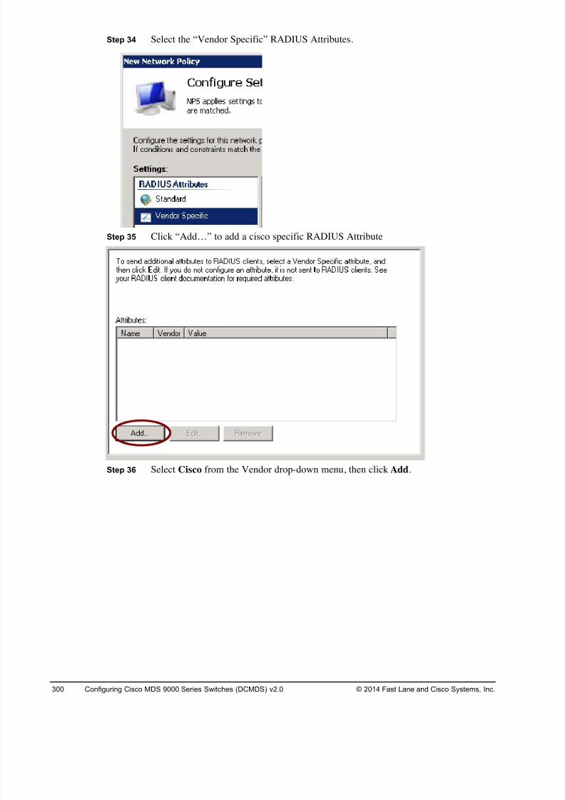
8/18/2019 FL_DCMDS_2.0.3_LG(1).pdf
http://slidepdf.com/reader/full/fldcmds203lg1pdf 300/482
300 Configuring Cisco MDS 9000 Series Switches (DCMDS) v2.0 © 2014 Fast Lane and Cisco Systems, Inc.
Step 34 Select the “Vendor Specific” RADIUS Attributes.
Step 35 Click “Add…” to add a cisco specific RADIUS Attribute
Step 36 Select Cisco from the Vendor drop-down menu, then click Add.
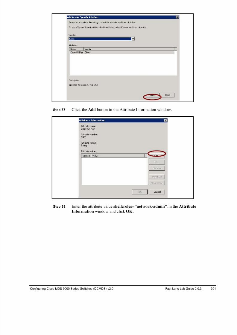
8/18/2019 FL_DCMDS_2.0.3_LG(1).pdf
http://slidepdf.com/reader/full/fldcmds203lg1pdf 301/482
Configuring Cisco MDS 9000 Series Switches (DCMDS) v2.0 Fast Lane Lab Guide 2.0.3 301
Step 37 Click the Add button in the Attribute Information window.
Step 38 Enter the attribute value shell:roles=”network-admin”, in the Attribute
Information window and click OK.
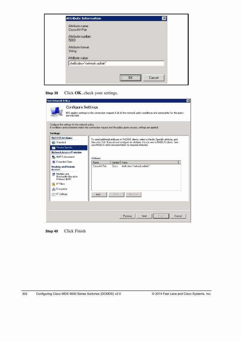
8/18/2019 FL_DCMDS_2.0.3_LG(1).pdf
http://slidepdf.com/reader/full/fldcmds203lg1pdf 302/482
302 Configuring Cisco MDS 9000 Series Switches (DCMDS) v2.0 © 2014 Fast Lane and Cisco Systems, Inc.
Step 39 Click OK, check your settings.
Step 40 Click Finish
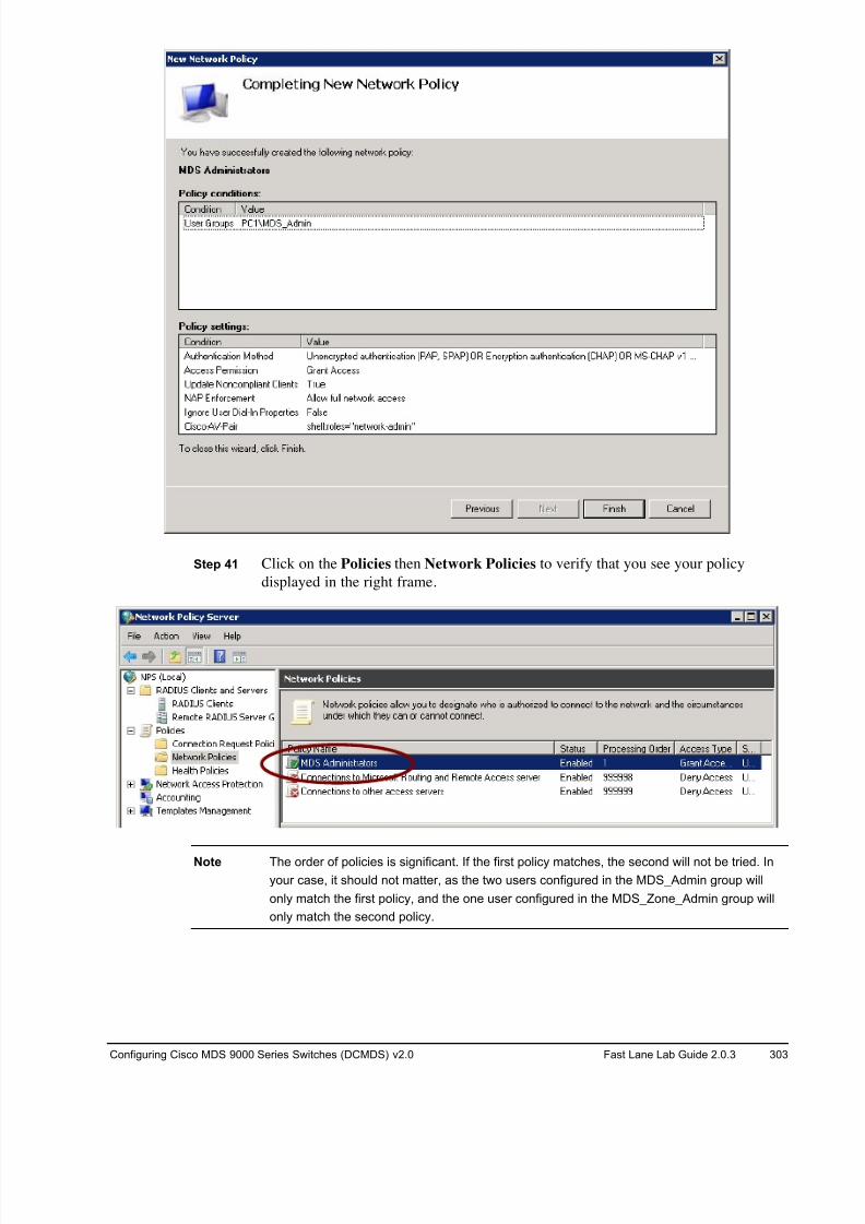
8/18/2019 FL_DCMDS_2.0.3_LG(1).pdf
http://slidepdf.com/reader/full/fldcmds203lg1pdf 303/482
Configuring Cisco MDS 9000 Series Switches (DCMDS) v2.0 Fast Lane Lab Guide 2.0.3 303
Step 41 Click on the Policies then Network Policies to verify that you see your policy
displayed in the right frame.
Note The order of policies is significant. If the first policy matches, the second will not be tried. In
your case, it should not matter, as the two users configured in the MDS_Admin group will
only match the first policy, and the one user configured in the MDS_Zone_Admin group will
only match the second policy.
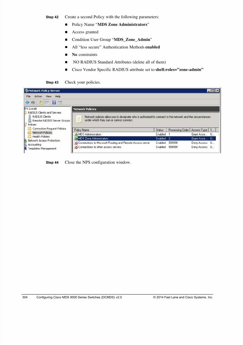
8/18/2019 FL_DCMDS_2.0.3_LG(1).pdf
http://slidepdf.com/reader/full/fldcmds203lg1pdf 304/482
304 Configuring Cisco MDS 9000 Series Switches (DCMDS) v2.0 © 2014 Fast Lane and Cisco Systems, Inc.
Step 42 Create a second Policy with the following parameters:
! Policy Name “MDS Zone Administrators”
! Access granted
! Condition User Group “MDS_Zone_Admin”
! All “less secure” Authentication Methods enabled
! No constraints
! NO RADIUS Standard Attributes (delete all of them)
! Cisco Vendor Specific RADIUS attribute set to shell:roles=”zone-admin”
Step 43 Check your policies.
Step 44 Close the NPS configuration window.
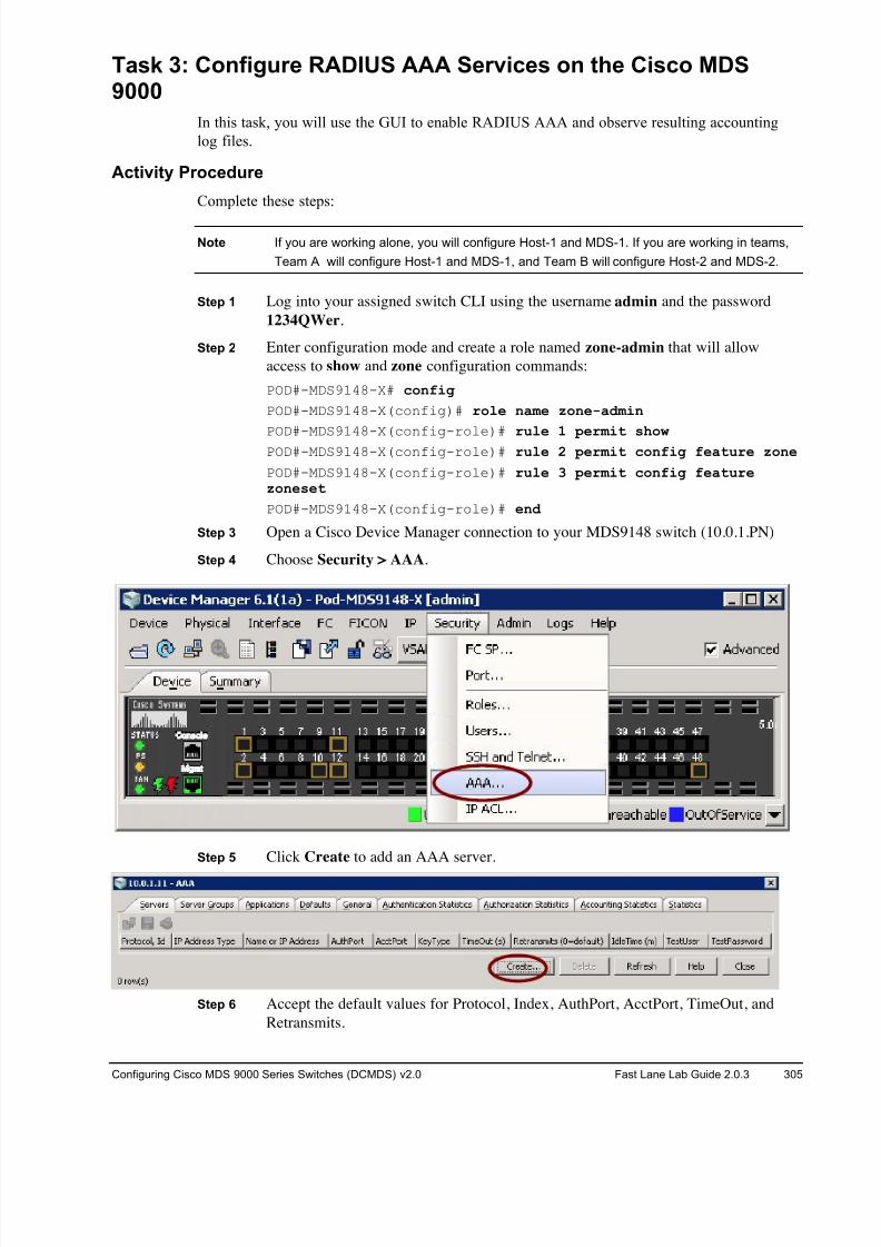
8/18/2019 FL_DCMDS_2.0.3_LG(1).pdf
http://slidepdf.com/reader/full/fldcmds203lg1pdf 305/482
Configuring Cisco MDS 9000 Series Switches (DCMDS) v2.0 Fast Lane Lab Guide 2.0.3 305
Task 3: Configure RADIUS AAA Services on the Cisco MDS9000
In this task, you will use the GUI to enable RADIUS AAA and observe resulting accounting
log files.
Activity Procedure
Complete these steps:
Note If you are working alone, you will configure Host-1 and MDS-1. If you are working in teams,
Team A will configure Host-1 and MDS-1, and Team B will configure Host-2 and MDS-2.
Step 1 Log into your assigned switch CLI using the username admin and the password
1234QWer.
Step 2 Enter configuration mode and create a role named zone-admin that will allow
access to show and zone configuration commands:
POD#-MDS9148-X# config
POD#-MDS9148-X(config)# role name zone-admin
POD#-MDS9148-X(config-role)# rule 1 permit show POD#-MDS9148-X(config-role)# rule 2 permit config feature zone
POD#-MDS9148-X(config-role)# rule 3 permit config featurezoneset
POD#-MDS9148-X(config-role)# end
Step 3 Open a Cisco Device Manager connection to your MDS9148 switch (10.0.1.PN)
Step 4 Choose Security > AAA.
Step 5 Click Create to add an AAA server.
Step 6 Accept the default values for Protocol, Index, AuthPort, AcctPort, TimeOut, and
Retransmits.
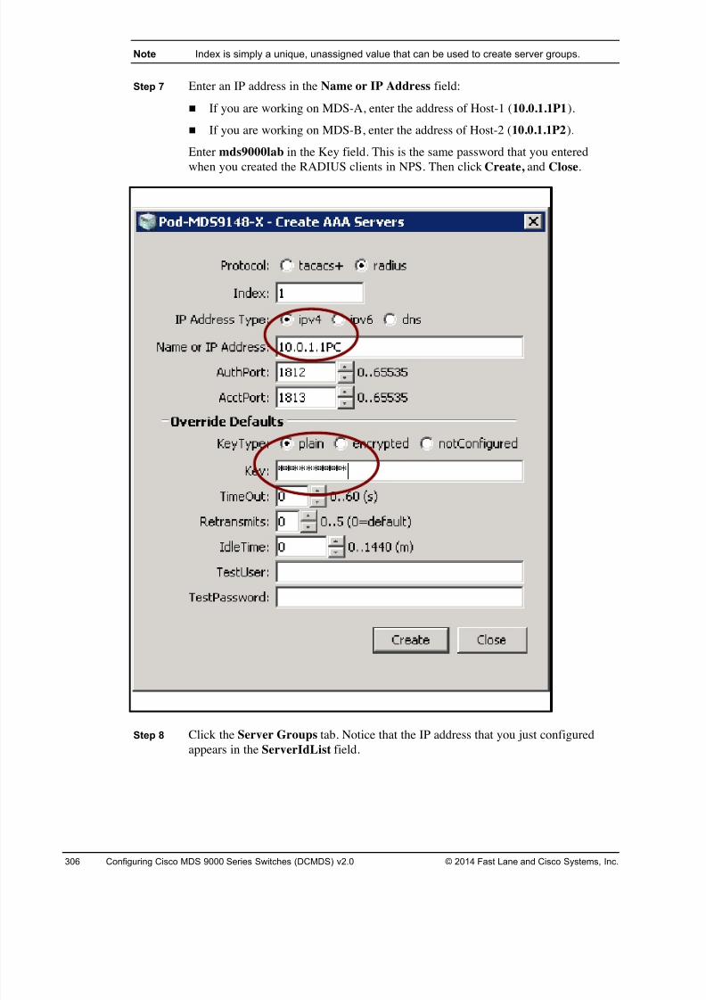
8/18/2019 FL_DCMDS_2.0.3_LG(1).pdf
http://slidepdf.com/reader/full/fldcmds203lg1pdf 306/482
306 Configuring Cisco MDS 9000 Series Switches (DCMDS) v2.0 © 2014 Fast Lane and Cisco Systems, Inc.
Note Index is simply a unique, unassigned value that can be used to create server groups.
Step 7 Enter an IP address in the Name or IP Address field:
! If you are working on MDS-A, enter the address of Host-1 (10.0.1.1P1).
! If you are working on MDS-B, enter the address of Host-2 (10.0.1.1P2).
Enter mds9000lab in the Key field. This is the same password that you entered
when you created the RADIUS clients in NPS. Then click Create, and Close.
Step 8 Click the Server Groups tab. Notice that the IP address that you just configured
appears in the ServerIdList field.
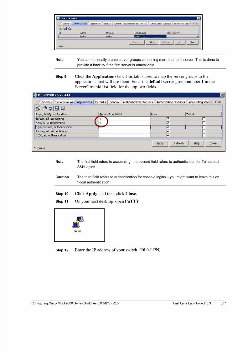
8/18/2019 FL_DCMDS_2.0.3_LG(1).pdf
http://slidepdf.com/reader/full/fldcmds203lg1pdf 307/482
Configuring Cisco MDS 9000 Series Switches (DCMDS) v2.0 Fast Lane Lab Guide 2.0.3 307
Note You can optionally create server groups containing more than one server. This is done to
provide a backup if the first server is unavailable.
Step 9 Click the Applications tab. This tab is used to map the server groups to the
applications that will use them. Enter the default server group number 1 in the
ServerGroupIdList field for the top two fields.
Note The first field refers to accounting, the second field refers to authentication for Telnet and
SSH logins
Caution The third field refers to authentication for console logins – you might want to leave this on
“local authentication”.
Step 10 Click Apply, and then click Close.
Step 11 On your host desktop, open PuTTY.
Step 12 Enter the IP address of your switch. (10.0.1.PN)
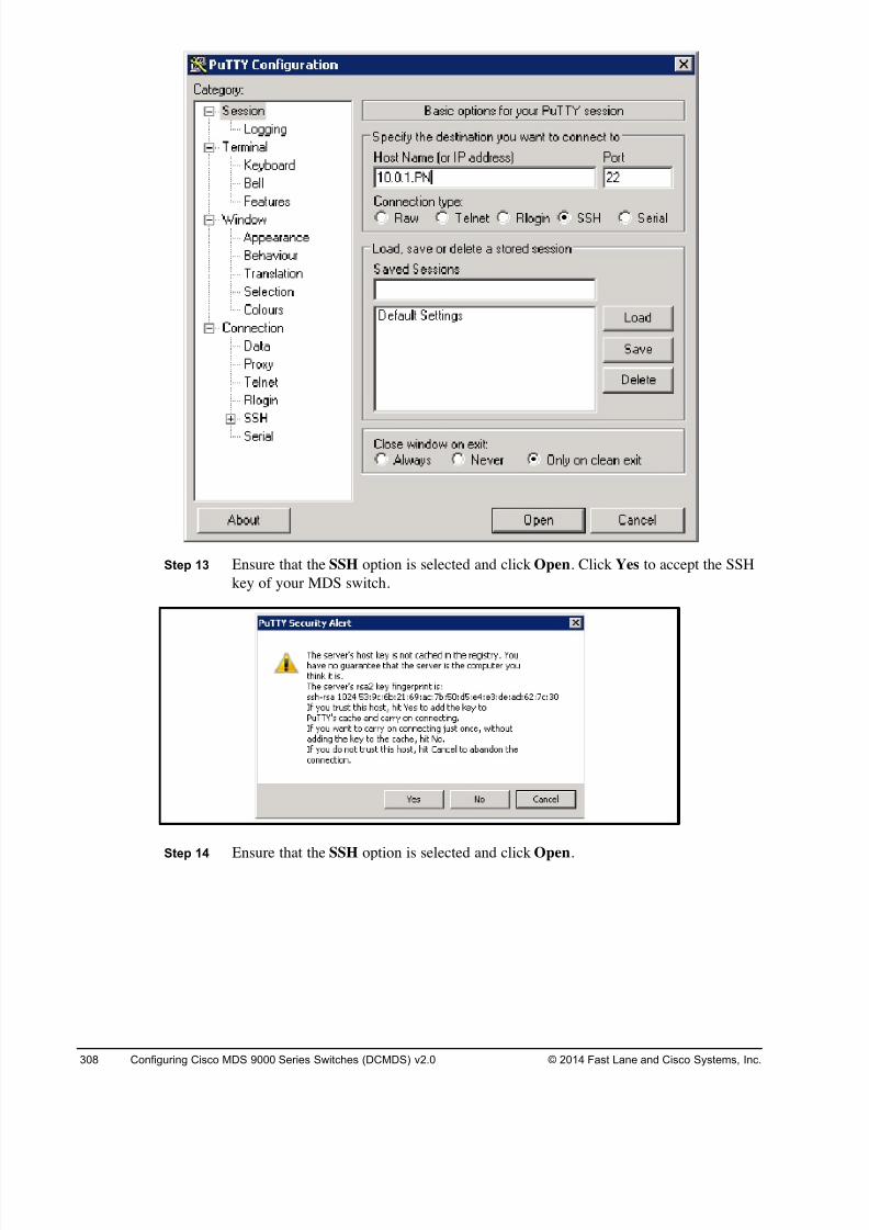
8/18/2019 FL_DCMDS_2.0.3_LG(1).pdf
http://slidepdf.com/reader/full/fldcmds203lg1pdf 308/482
308 Configuring Cisco MDS 9000 Series Switches (DCMDS) v2.0 © 2014 Fast Lane and Cisco Systems, Inc.
Step 13 Ensure that the SSH option is selected and click Open. Click Yes to accept the SSH
key of your MDS switch.
Step 14 Ensure that the SSH option is selected and click Open.
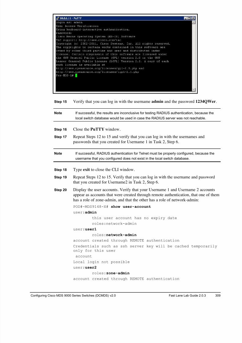
8/18/2019 FL_DCMDS_2.0.3_LG(1).pdf
http://slidepdf.com/reader/full/fldcmds203lg1pdf 309/482
Configuring Cisco MDS 9000 Series Switches (DCMDS) v2.0 Fast Lane Lab Guide 2.0.3 309
Step 15 Verify that you can log in with the username admin and the password 1234QWer.
Note If successful, the results are inconclusive for testing RADIUS authentication, because the
local switch database would be used in case the RADIUS server was not reachable.
Step 16 Close the PuTTY window.
Step 17 Repeat Steps 12 to 15 and verify that you can log in with the usernames and
passwords that you created for Username 1 in Task 2, Step 6.
Note If successful, RADIUS authentication for Telnet must be properly configured, because the
username that you configured does not exist in the local switch database.
Step 18 Type exit to close the CLI window.
Step 19 Repeat Steps 12 to 15. Verify that you can log in with the username and password
that you created for Username2 in Task 2, Step 6.
Step 20 Display the user accounts. Verify that your Username 1 and Username 2 accounts
appear as accounts that were created through remote authentication, that one of them
has a role of zone-admin, and that the other has a role of network-admin:
POD#-MDS9148-X# show user-account
user:admin
this user account has no expiry date
roles:network-admin
user:user1
roles:network-admin
account created through REMOTE authenticationCredentials such as ssh server key will be cached temporarilyonly for this user
account
Local login not possible
user:user2
roles:zone-admin
account created through REMOTE authentication
8/18/2019 FL_DCMDS_2.0.3_LG(1).pdf
http://slidepdf.com/reader/full/fldcmds203lg1pdf 310/482
310 Configuring Cisco MDS 9000 Series Switches (DCMDS) v2.0 © 2014 Fast Lane and Cisco Systems, Inc.
Credentials such as ssh server key will be cached temporarilyonly for this user
account
Local login not possible
Step 21 Enter configuration mode and display all configuration mode commands that are
available to your Username 2. Verify that zone and zone set configuration are
essentially the only tasks that this user can perform.
Pod-MDS9148-X# ?
configure Enter configuration mode
show Show running system information
end Go to exec mode
exit Exit from command interpreter
Pod-MDS9148-X# conf
Enter configuration commands, one per line. End with CNTL/Z.
Pod-MDS9148-X(config)# ?
zone Zone configuration commands
zoneset Zoneset configuration commands
end Go to exec mode
exit Exit from command interpreter
Pod-MDS9148-X(config)#
Note This verifies that RADIUS authentication and authorization are properly configured for
Telnet. As an optional activity, verify that this is also true for console access.
Step 22 Type end and then exit to close the CLI window.
Activity Verification
To verify your configuration, display the configured RADIUS server:
POD#-MDS9148-X# show radius-server
retransmission count:1
timeout value:5
deadtime value:0
total number of servers:1
following RADIUS servers are configured:
10.0.1.1PN:
available for authentication on port:1812
available for accounting on port:1813
RADIUS shared secret:*******
8/18/2019 FL_DCMDS_2.0.3_LG(1).pdf
http://slidepdf.com/reader/full/fldcmds203lg1pdf 311/482
Configuring Cisco MDS 9000 Series Switches (DCMDS) v2.0 Fast Lane Lab Guide 2.0.3 311
Task 4: Configure AAA Server Monitoring
In this task, you will create a test user and configure AAA server monitoring.
Activity Procedure
Complete these steps on both switches:
Step 1 Display the configured RADIUS server to determine its IP address:POD#-MDS9148-X# show radius-server
retransmission count:1
timeout value:5
deadtime value:0
total number of servers:1
following RADIUS servers are configured:
10.0.1.111:
available for authentication on port:1812
available for accounting on port:1813
RADIUS shared secret:*******
Note The test idle timer specifies the interval during which a RADIUS server receives no requests
before the MDS switch sends out a test packet. The default idle timer value is 0 minutes.
When the idle-time interval is 0 minutes, RADIUS server monitoring is not performed.
Step 2 Configure the test user testuser with the default password test and a test idle time of
20 minutes to specify the interval during which a RADIUS server receives no
requests before the MDS switch sends out a test packet:
POD#-MDS9148-X(config)# radius-server host 10.0.1.1PN test usernametestuser idle-time 20
(IP = 10.0.1.1P1 for Host-1 or 10.0.1.1PN for Host-2)
Caution If the dead timer of a dead RADIUS server expires before it is sent a RADIUS test message,
that server is marked as alive again even if it is still not responding. Ensure that the dead-
timer value is greater than the test user idle-time value.
Step 3 Configure a dead-timer value of 30 minutes for the RADIUS server:
POD#-MDS9148-X(config)# radius-server deadtime 30
POD#-MDS9148-X(config)# end
8/18/2019 FL_DCMDS_2.0.3_LG(1).pdf
http://slidepdf.com/reader/full/fldcmds203lg1pdf 312/482
312 Configuring Cisco MDS 9000 Series Switches (DCMDS) v2.0 © 2014 Fast Lane and Cisco Systems, Inc.
Activity Verification
Complete these steps to verify your configuration:
Step 1 Send a test message to a RADIUS server using the username testuser and password
test:
POD#-MDS9148-X# test aaa server radius 10.0.1.1PN testusertest
user has failed authentication
Note The test user will fail authentication. It is recommended that the test username is not the
same as an existing user in the RADIUS database for security reasons.
Step 2 Display the monitoring statistics for the RADIUS server, where IP = 10.0.1.1P1 for
Host-1 and/or IP = 10.0.1.1P2 for Host-2:
POD#-MDS9148-X# show radius-server statistics 10.0.1.1PN
Server is alive since 0 hrs, 34 min, 21 sec
Monitoring Statistics
Time in previous state: N/A
Number of times dead: 0
Total time in dead state: N/A
Authentication Statistics
failed transactions: 0
sucessfull transactions: 10
requests sent: 10
requests timed out: 0
responses with no matching requests: 0
responses not processed: 0
responses containing errors: 0
Accounting Statistics
failed transactions: 0
sucessfull transactions: 27
requests sent: 27
requests timed out: 0
responses with no matching requests: 0
responses not processed: 0
responses containing errors: 0
8/18/2019 FL_DCMDS_2.0.3_LG(1).pdf
http://slidepdf.com/reader/full/fldcmds203lg1pdf 313/482
Configuring Cisco MDS 9000 Series Switches (DCMDS) v2.0 Fast Lane Lab Guide 2.0.3 313
Task 5: Cleanup
In this task, you prepare your lab for the next exercise.
Activity Procedure
Complete the following steps.
18. Open a console session to your assigned switch (MDS9148-A or MDS9148-B) by clicking the blue switch
icon in the remote lab GUI.Switch login: admin
Password: 1234QWer
19. Clear the current startup configuration ON YOUR 9148s ONLY, DO NOT CLEAR THE CORE
9222is!!! .
# write erase
The following message is displayed:
Warning: This command will erase the startup-configuration.
Do you wish to proceed anyway? [y/n] [N]
Type y to proceed.
20. Reboot the 9148 switch.
# reload
This command will reboot the system. (y/n)?
Type y to proceed.
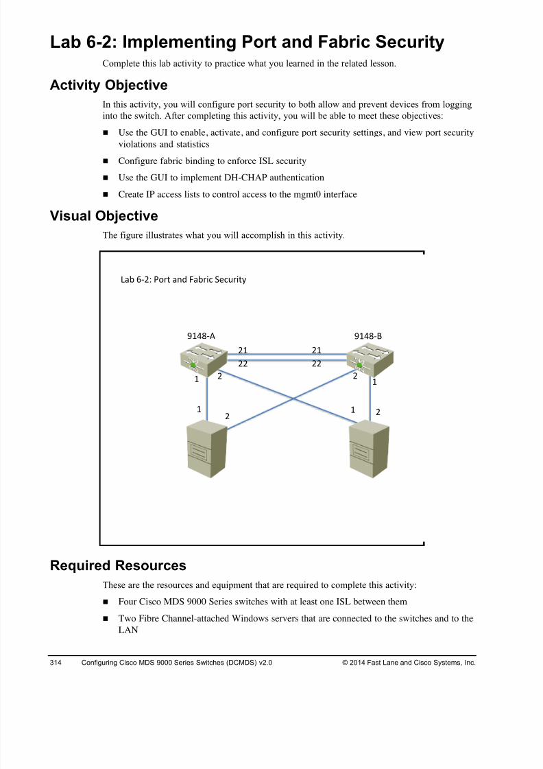
8/18/2019 FL_DCMDS_2.0.3_LG(1).pdf
http://slidepdf.com/reader/full/fldcmds203lg1pdf 314/482
314 Configuring Cisco MDS 9000 Series Switches (DCMDS) v2.0 © 2014 Fast Lane and Cisco Systems, Inc.
Lab 6-2: Implementing Port and Fabric Security Complete this lab activity to practice what you learned in the related lesson.
Activity Objective
In this activity, you will configure port security to both allow and prevent devices from logging
into the switch. After completing this activity, you will be able to meet these objectives:
! Use the GUI to enable, activate, and configure port security settings, and view port securityviolations and statistics
! Configure fabric binding to enforce ISL security
! Use the GUI to implement DH-CHAP authentication
! Create IP access lists to control access to the mgmt0 interface
Visual Objective
The figure illustrates what you will accomplish in this activity.
Required Resources
These are the resources and equipment that are required to complete this activity:
! Four Cisco MDS 9000 Series switches with at least one ISL between them
! Two Fibre Channel-attached Windows servers that are connected to the switches and to the
LAN
!"# %&'( )*+, "-. /"#+01 2314+0,5
6 6' '
'6
''
'6
''
6'
'6
7689&:7689&;
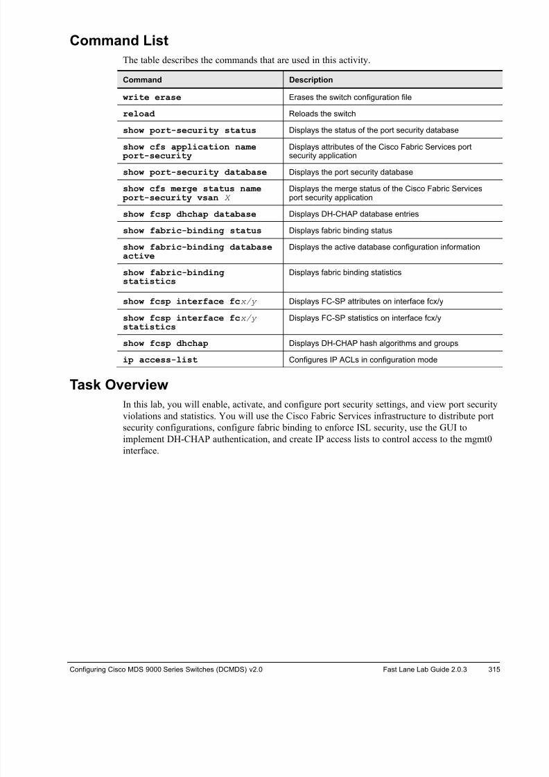
8/18/2019 FL_DCMDS_2.0.3_LG(1).pdf
http://slidepdf.com/reader/full/fldcmds203lg1pdf 315/482
Configuring Cisco MDS 9000 Series Switches (DCMDS) v2.0 Fast Lane Lab Guide 2.0.3 315
Command List
The table describes the commands that are used in this activity.
Command Description
write erase Erases the switch configuration file
reload Reloads the switch
show port-security status Displays the status of the port security database
show cfs application name port-security
Displays attributes of the Cisco Fabric Services portsecurity application
show port-security database Displays the port security database
show cfs merge status name port-security vsan X
Displays the merge status of the Cisco Fabric Servicesport security application
show fcsp dhchap database Displays DH-CHAP database entries
show fabric-binding status Displays fabric binding status
show fabric-binding databaseactive
Displays the active database configuration information
show fabric-bindingstatistics
Displays fabric binding statistics
show fcsp interface fcx/y Displays FC-SP attributes on interface fcx/y
show fcsp interface fcx/y statistics
Displays FC-SP statistics on interface fcx/y
show fcsp dhchap Displays DH-CHAP hash algorithms and groups
ip access-list Configures IP ACLs in configuration mode
Task Overview
In this lab, you will enable, activate, and configure port security settings, and view port securityviolations and statistics. You will use the Cisco Fabric Services infrastructure to distribute port
security configurations, configure fabric binding to enforce ISL security, use the GUI to
implement DH-CHAP authentication, and create IP access lists to control access to the mgmt0
interface.
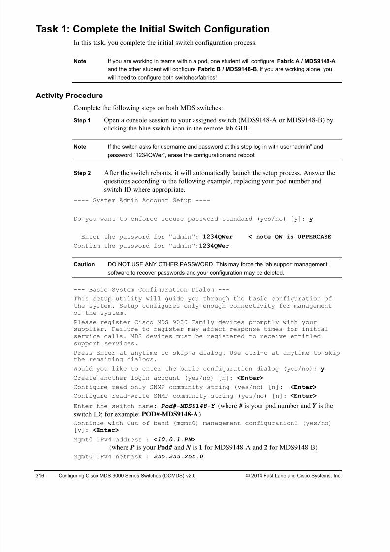
8/18/2019 FL_DCMDS_2.0.3_LG(1).pdf
http://slidepdf.com/reader/full/fldcmds203lg1pdf 316/482
316 Configuring Cisco MDS 9000 Series Switches (DCMDS) v2.0 © 2014 Fast Lane and Cisco Systems, Inc.
Task 1: Complete the Initial Switch Configuration
In this task, you complete the initial switch configuration process.
Note If you are working in teams within a pod, one student will configure Fabric A / MDS9148-A
and the other student will configure Fabric B / MDS9148-B. If you are working alone, you
will need to configure both switches/fabrics!
Activity ProcedureComplete the following steps on both MDS switches:
Step 1 Open a console session to your assigned switch (MDS9148-A or MDS9148-B) by
clicking the blue switch icon in the remote lab GUI.
Note If the switch asks for username and password at this step log in with user “admin” and
password “1234QWer”, erase the configuration and reboot.
Step 2 After the switch reboots, it will automatically launch the setup process. Answer the
questions according to the following example, replacing your pod number and
switch ID where appropriate.
---- System Admin Account Setup ----
Do you want to enforce secure password standard (yes/no) [y]: y
Enter the password for "admin": 1234QWer < note QW is UPPERCASE
Confirm the password for "admin":1234QWer
Caution DO NOT USE ANY OTHER PASSWORD. This may force the lab support management
software to recover passwords and your configuration may be deleted.
--- Basic System Configuration Dialog ---This setup utility will guide you through the basic configuration ofthe system. Setup configures only enough connectivity for managementof the system.
Please register Cisco MDS 9000 Family devices promptly with yoursupplier. Failure to register may affect response times for initialservice calls. MDS devices must be registered to receive entitledsupport services.
Press Enter at anytime to skip a dialog. Use ctrl-c at anytime to skipthe remaining dialogs.
Would you like to enter the basic configuration dialog (yes/no): y
Create another login account (yes/no) [n]: <Enter>
Configure read-only SNMP community string (yes/no) [n]: <Enter> Configure read-write SNMP community string (yes/no) [n]: <Enter>
Enter the switch name: Pod#-MDS9148-Y (where # is your pod number and Y is the
switch ID; for example: POD#-MDS9148-A)
Continue with Out-of-band (mgmt0) management configuration? (yes/no)[y]: <Enter>
Mgmt0 IPv4 address : <10.0.1.PN >
(where P is your Pod# and N is 1 for MDS9148-A and 2 for MDS9148-B)
Mgmt0 IPv4 netmask : 255.255.255.0
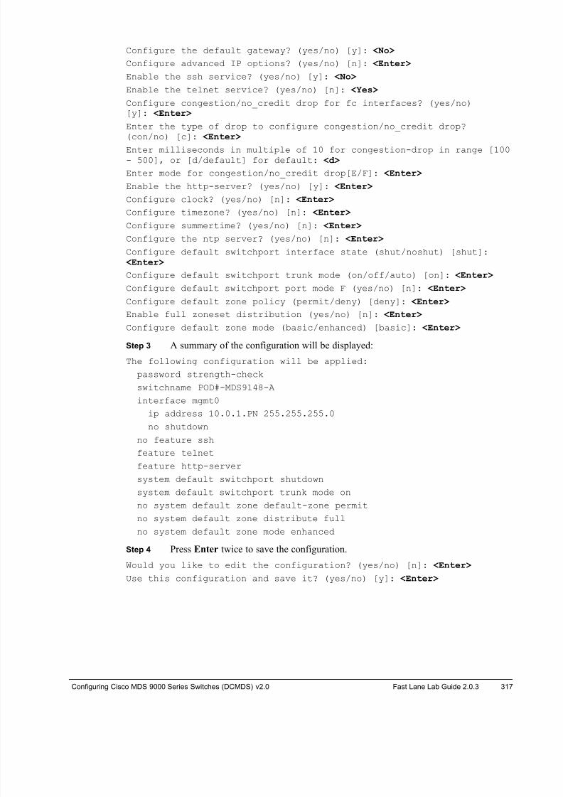
8/18/2019 FL_DCMDS_2.0.3_LG(1).pdf
http://slidepdf.com/reader/full/fldcmds203lg1pdf 317/482
Configuring Cisco MDS 9000 Series Switches (DCMDS) v2.0 Fast Lane Lab Guide 2.0.3 317
Configure the default gateway? (yes/no) [y]: <No>
Configure advanced IP options? (yes/no) [n]: <Enter>
Enable the ssh service? (yes/no) [y]: <No>
Enable the telnet service? (yes/no) [n]: <Yes>
Configure congestion/no_credit drop for fc interfaces? (yes/no)[y]: <Enter>
Enter the type of drop to configure congestion/no_credit drop?
(con/no) [c]: <Enter>Enter milliseconds in multiple of 10 for congestion-drop in range [100- 500], or [d/default] for default: <d>
Enter mode for congestion/no_credit drop[E/F]: <Enter>
Enable the http-server? (yes/no) [y]: <Enter>
Configure clock? (yes/no) [n]: <Enter>
Configure timezone? (yes/no) [n]: <Enter>
Configure summertime? (yes/no) [n]: <Enter>
Configure the ntp server? (yes/no) [n]: <Enter>
Configure default switchport interface state (shut/noshut) [shut]: <Enter>
Configure default switchport trunk mode (on/off/auto) [on]: <Enter> Configure default switchport port mode F (yes/no) [n]: <Enter>
Configure default zone policy (permit/deny) [deny]: <Enter>
Enable full zoneset distribution (yes/no) [n]: <Enter>
Configure default zone mode (basic/enhanced) [basic]: <Enter>
Step 3 A summary of the configuration will be displayed:
The following configuration will be applied:
password strength-check
switchname POD#-MDS9148-A
interface mgmt0
ip address 10.0.1.PN 255.255.255.0
no shutdown
no feature ssh
feature telnet
feature http-server
system default switchport shutdown
system default switchport trunk mode on
no system default zone default-zone permit
no system default zone distribute full
no system default zone mode enhanced
Step 4 Press Enter twice to save the configuration.
Would you like to edit the configuration? (yes/no) [n]: <Enter>
Use this configuration and save it? (yes/no) [y]: <Enter>
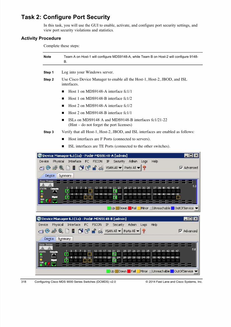
8/18/2019 FL_DCMDS_2.0.3_LG(1).pdf
http://slidepdf.com/reader/full/fldcmds203lg1pdf 318/482
318 Configuring Cisco MDS 9000 Series Switches (DCMDS) v2.0 © 2014 Fast Lane and Cisco Systems, Inc.
Task 2: Configure Port Security
In this task, you will use the GUI to enable, activate, and configure port security settings, and
view port security violations and statistics.
Activity Procedure
Complete these steps:
Note Team A on Host-1 will configure MDS9148-A, while Team B on Host-2 will configure 9148-B.
Step 1 Log into your Windows server.
Step 2 Use Cisco Device Manager to enable all the Host-1, Host-2, JBOD, and ISL
interfaces.
! Host 1 on MDS9148-A interface fc1/1
! Host 1 on MDS9148-B interface fc1/2
! Host 2 on MDS9148-A interface fc1/2
!
Host 2 on MDS9148-B interface fc1/1! ISLs on MDS9148 A and MDS9148-B interfaces fc1/21-22
(Hint – do not forget the port licenses)
Step 3 Verify that all Host-1, Host-2, JBOD, and ISL interfaces are enabled as follows:
! Host interfaces are F Ports (connected to servers).
! ISL interfaces are TE Ports (connected to the other switches).
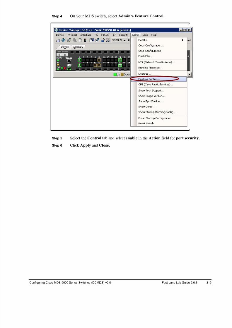
8/18/2019 FL_DCMDS_2.0.3_LG(1).pdf
http://slidepdf.com/reader/full/fldcmds203lg1pdf 319/482
Configuring Cisco MDS 9000 Series Switches (DCMDS) v2.0 Fast Lane Lab Guide 2.0.3 319
Step 4 On your MDS switch, select Admin > Feature Control.
Step 5 Select the Control tab and select enable in the Action field for port security.
Step 6 Click Apply and Close.
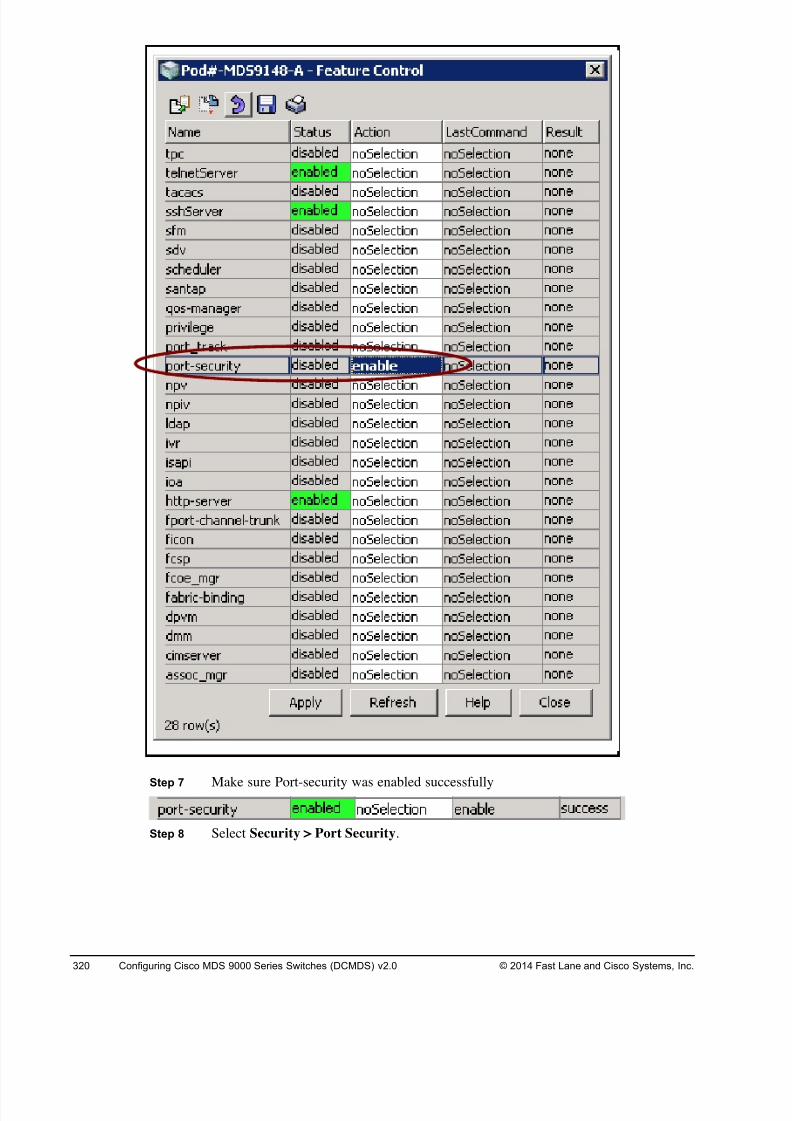
8/18/2019 FL_DCMDS_2.0.3_LG(1).pdf
http://slidepdf.com/reader/full/fldcmds203lg1pdf 320/482
320 Configuring Cisco MDS 9000 Series Switches (DCMDS) v2.0 © 2014 Fast Lane and Cisco Systems, Inc.
Step 7 Make sure Port-security was enabled successfully
Step 8 Select Security > Port Security.
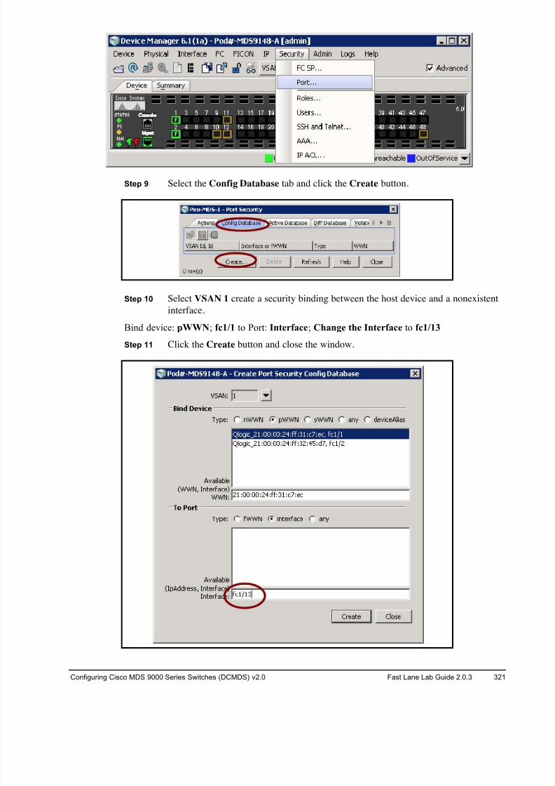
8/18/2019 FL_DCMDS_2.0.3_LG(1).pdf
http://slidepdf.com/reader/full/fldcmds203lg1pdf 321/482
Configuring Cisco MDS 9000 Series Switches (DCMDS) v2.0 Fast Lane Lab Guide 2.0.3 321
Step 9 Select the Config Database tab and click the Create button.
Step 10 Select VSAN 1 create a security binding between the host device and a nonexistent
interface.
Bind device: pWWN; fc1/1 to Port: Interface; Change the Interface to fc1/13
Step 11 Click the Create button and close the window.
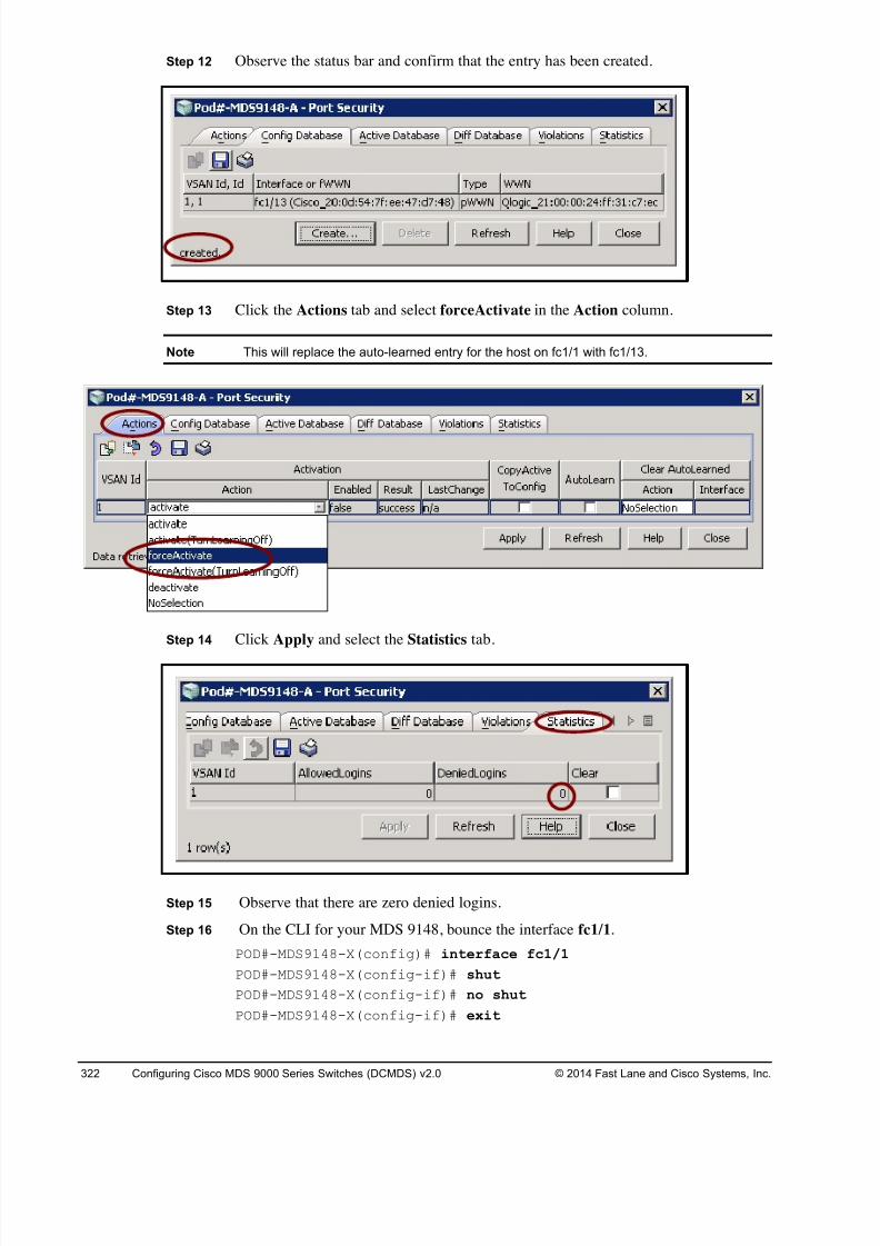
8/18/2019 FL_DCMDS_2.0.3_LG(1).pdf
http://slidepdf.com/reader/full/fldcmds203lg1pdf 322/482
322 Configuring Cisco MDS 9000 Series Switches (DCMDS) v2.0 © 2014 Fast Lane and Cisco Systems, Inc.
Step 12 Observe the status bar and confirm that the entry has been created.
Step 13 Click the Actions tab and select forceActivate in the Action column.
Note This will replace the auto-learned entry for the host on fc1/1 with fc1/13.
Step 14 Click Apply and select the Statistics tab.
Step 15 Observe that there are zero denied logins.
Step 16 On the CLI for your MDS 9148, bounce the interface fc1/1.
POD#-MDS9148-X(config)# interface fc1/1
POD#-MDS9148-X(config-if)# shut
POD#-MDS9148-X(config-if)# no shut
POD#-MDS9148-X(config-if)# exit
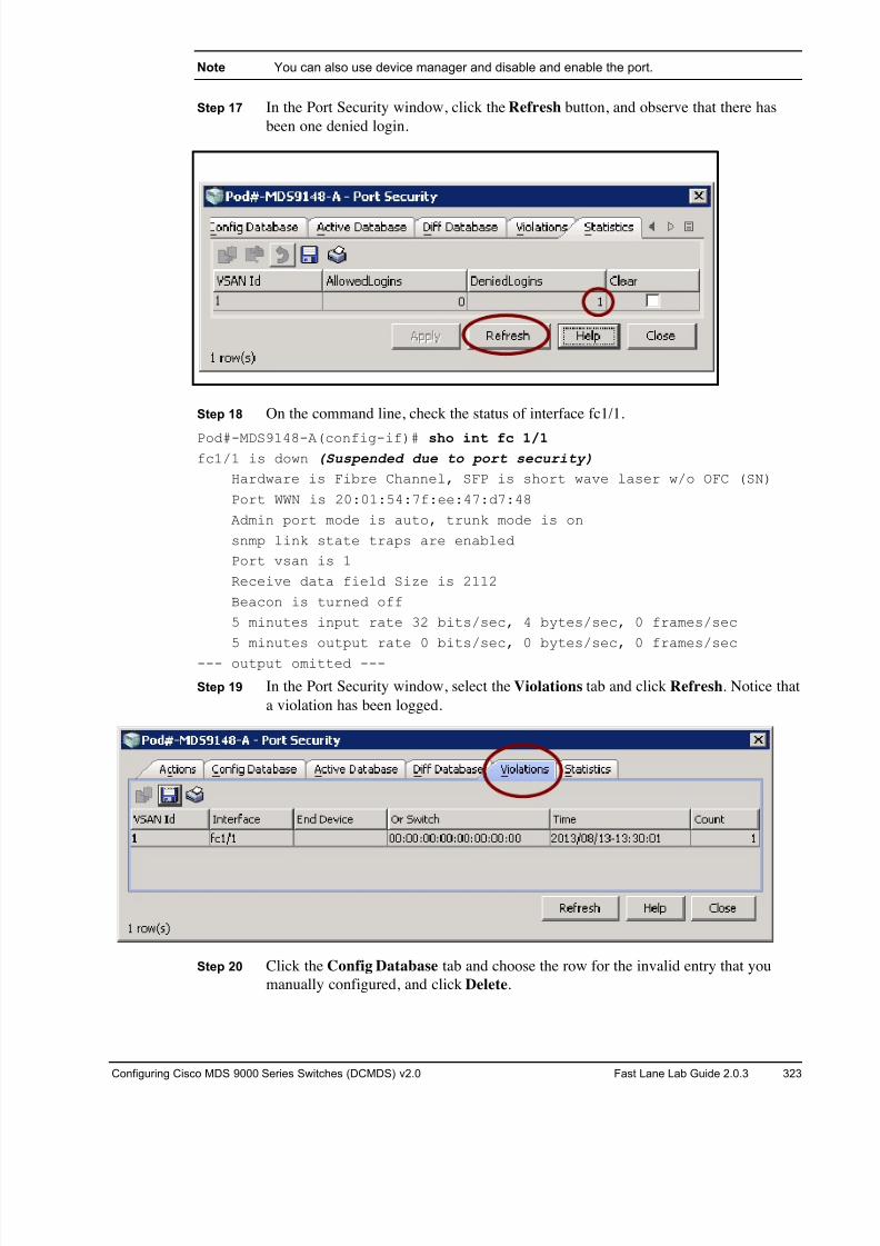
8/18/2019 FL_DCMDS_2.0.3_LG(1).pdf
http://slidepdf.com/reader/full/fldcmds203lg1pdf 323/482
Configuring Cisco MDS 9000 Series Switches (DCMDS) v2.0 Fast Lane Lab Guide 2.0.3 323
Note You can also use device manager and disable and enable the port.
Step 17 In the Port Security window, click the Refresh button, and observe that there has
been one denied login.
Step 18 On the command line, check the status of interface fc1/1.
Pod#-MDS9148-A(config-if)# sho int fc 1/1 fc1/1 is down (Suspended due to port security)
Hardware is Fibre Channel, SFP is short wave laser w/o OFC (SN)
Port WWN is 20:01:54:7f:ee:47:d7:48
Admin port mode is auto, trunk mode is on
snmp link state traps are enabled
Port vsan is 1
Receive data field Size is 2112
Beacon is turned off
5 minutes input rate 32 bits/sec, 4 bytes/sec, 0 frames/sec
5 minutes output rate 0 bits/sec, 0 bytes/sec, 0 frames/sec
--- output omitted ---
Step 19 In the Port Security window, select the Violations tab and click Refresh. Notice that
a violation has been logged.
Step 20 Click the Config Database tab and choose the row for the invalid entry that you
manually configured, and click Delete.
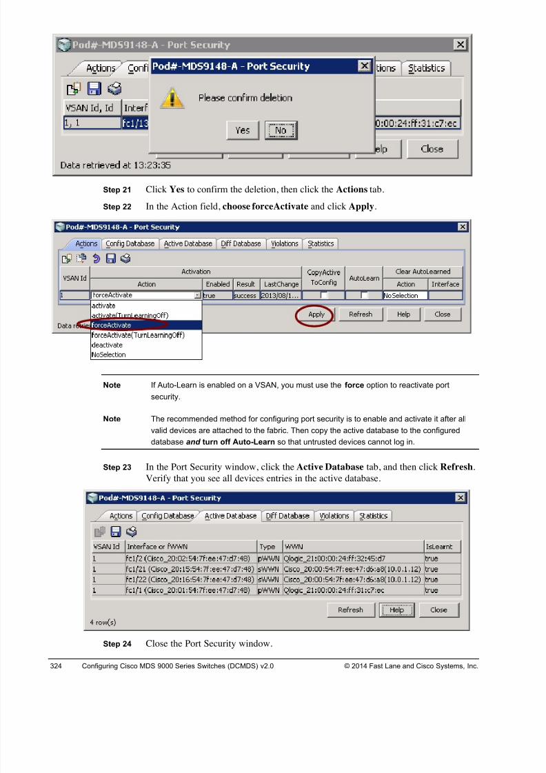
8/18/2019 FL_DCMDS_2.0.3_LG(1).pdf
http://slidepdf.com/reader/full/fldcmds203lg1pdf 324/482
324 Configuring Cisco MDS 9000 Series Switches (DCMDS) v2.0 © 2014 Fast Lane and Cisco Systems, Inc.
Step 21 Click Yes to confirm the deletion, then click the Actions tab.
Step 22 In the Action field, choose forceActivate and click Apply.
Note If Auto-Learn is enabled on a VSAN, you must use the force option to reactivate port
security.
Note The recommended method for configuring port security is to enable and activate it after all
valid devices are attached to the fabric. Then copy the active database to the configured
database and turn off Auto-Learn so that untrusted devices cannot log in.
Step 23 In the Port Security window, click the Active Database tab, and then click Refresh.
Verify that you see all devices entries in the active database.
Step 24 Close the Port Security window.
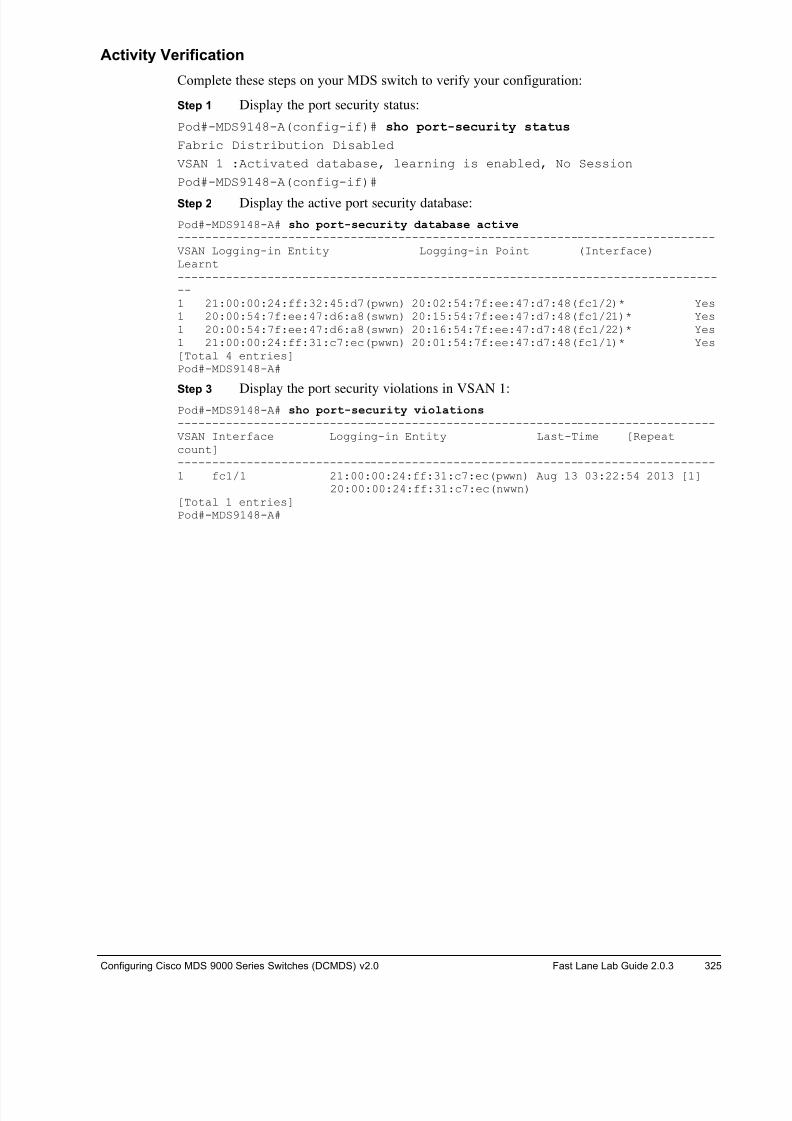
8/18/2019 FL_DCMDS_2.0.3_LG(1).pdf
http://slidepdf.com/reader/full/fldcmds203lg1pdf 325/482
Configuring Cisco MDS 9000 Series Switches (DCMDS) v2.0 Fast Lane Lab Guide 2.0.3 325
Activity Verification
Complete these steps on your MDS switch to verify your configuration:
Step 1 Display the port security status:
Pod#-MDS9148-A(config-if)# sho port-security status
Fabric Distribution Disabled
VSAN 1 :Activated database, learning is enabled, No Session
Pod#-MDS9148-A(config-if)#
Step 2 Display the active port security database:
Pod#-MDS9148-A# sho port-security database active ------------------------------------------------------------------------------VSAN Logging-in Entity Logging-in Point (Interface)Learnt--------------------------------------------------------------------------------1 21:00:00:24:ff:32:45:d7(pwwn) 20:02:54:7f:ee:47:d7:48(fc1/2)* Yes1 20:00:54:7f:ee:47:d6:a8(swwn) 20:15:54:7f:ee:47:d7:48(fc1/21)* Yes1 20:00:54:7f:ee:47:d6:a8(swwn) 20:16:54:7f:ee:47:d7:48(fc1/22)* Yes1 21:00:00:24:ff:31:c7:ec(pwwn) 20:01:54:7f:ee:47:d7:48(fc1/1)* Yes[Total 4 entries]Pod#-MDS9148-A#
Step 3 Display the port security violations in VSAN 1:Pod#-MDS9148-A# sho port-security violations ------------------------------------------------------------------------------VSAN Interface Logging-in Entity Last-Time [Repeatcount]------------------------------------------------------------------------------1 fc1/1 21:00:00:24:ff:31:c7:ec(pwwn) Aug 13 03:22:54 2013 [1]
20:00:00:24:ff:31:c7:ec(nwwn)[Total 1 entries]Pod#-MDS9148-A#
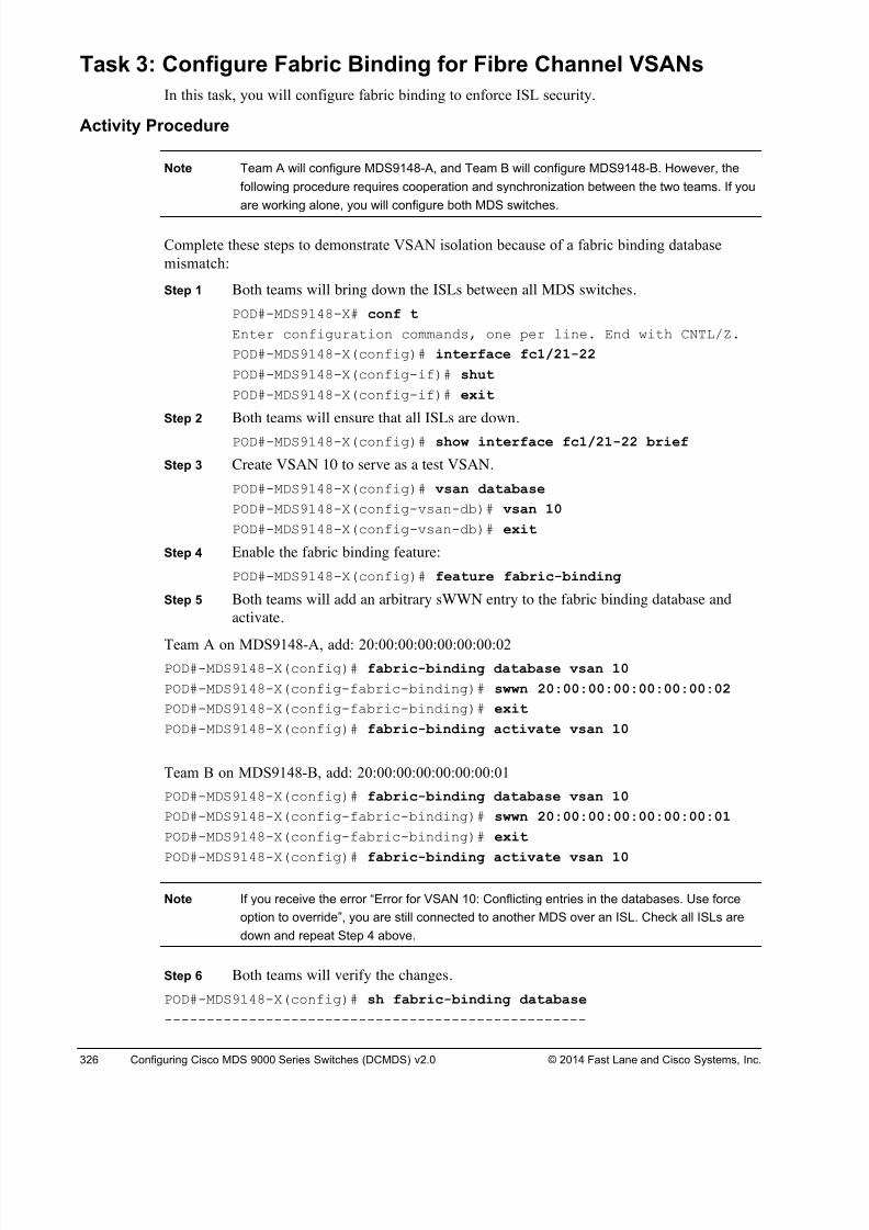
8/18/2019 FL_DCMDS_2.0.3_LG(1).pdf
http://slidepdf.com/reader/full/fldcmds203lg1pdf 326/482
326 Configuring Cisco MDS 9000 Series Switches (DCMDS) v2.0 © 2014 Fast Lane and Cisco Systems, Inc.
Task 3: Configure Fabric Binding for Fibre Channel VSANs
In this task, you will configure fabric binding to enforce ISL security.
Activity Procedure
Note Team A will configure MDS9148-A, and Team B will configure MDS9148-B. However, the
following procedure requires cooperation and synchronization between the two teams. If you
are working alone, you will configure both MDS switches.
Complete these steps to demonstrate VSAN isolation because of a fabric binding database
mismatch:
Step 1 Both teams will bring down the ISLs between all MDS switches.
POD#-MDS9148-X# conf t
Enter configuration commands, one per line. End with CNTL/Z.
POD#-MDS9148-X(config)# interface fc1/21-22
POD#-MDS9148-X(config-if)# shut
POD#-MDS9148-X(config-if)# exit
Step 2 Both teams will ensure that all ISLs are down.
POD#-MDS9148-X(config)# show interface fc1/21-22 brief
Step 3 Create VSAN 10 to serve as a test VSAN.
POD#-MDS9148-X(config)# vsan database
POD#-MDS9148-X(config-vsan-db)# vsan 10
POD#-MDS9148-X(config-vsan-db)# exit
Step 4 Enable the fabric binding feature:
POD#-MDS9148-X(config)# feature fabric-binding
Step 5 Both teams will add an arbitrary sWWN entry to the fabric binding database and
activate.
Team A on MDS9148-A, add: 20:00:00:00:00:00:00:02POD#-MDS9148-X(config)# fabric-binding database vsan 10
POD#-MDS9148-X(config-fabric-binding)# swwn 20:00:00:00:00:00:00:02
POD#-MDS9148-X(config-fabric-binding)# exit
POD#-MDS9148-X(config)# fabric-binding activate vsan 10
Team B on MDS9148-B, add: 20:00:00:00:00:00:00:01
POD#-MDS9148-X(config)# fabric-binding database vsan 10
POD#-MDS9148-X(config-fabric-binding)# swwn 20:00:00:00:00:00:00:01
POD#-MDS9148-X(config-fabric-binding)# exit
POD#-MDS9148-X(config)# fabric-binding activate vsan 10
Note If you receive the error “Error for VSAN 10: Conflicting entries in the databases. Use force
option to override”, you are still connected to another MDS over an ISL. Check all ISLs are
down and repeat Step 4 above.
Step 6 Both teams will verify the changes.
POD#-MDS9148-X(config)# sh fabric-binding database
--------------------------------------------------
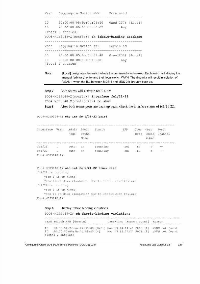
8/18/2019 FL_DCMDS_2.0.3_LG(1).pdf
http://slidepdf.com/reader/full/fldcmds203lg1pdf 327/482
Configuring Cisco MDS 9000 Series Switches (DCMDS) v2.0 Fast Lane Lab Guide 2.0.3 327
Vsan Logging-in Switch WWN Domain-id
--------------------------------------------------
10 20:00:00:05:9b:7d:05:40 0xed(237) [Local]
10 20:00:00:00:00:00:00:02 Any
[Total 2 entries]
POD#-MDS9148-X(config)# sh fabric-binding database
--------------------------------------------------
Vsan Logging-in Switch WWN Domain-id
--------------------------------------------------
10 20:00:00:05:9b:7d:01:40 0xee(238) [Local]
10 20:00:00:00:00:00:00:01 Any[Total 2 entries]
Note [Local] designates the switch where the command was invoked. Each switch will display the
manual (arbitrary) entry and their local switch WWN. The disparity will result in isolation of
VSAN 1 when the ISL between MDS-1 and MDS-2 is brought back up.
Step 7 Both teams will activate fc1/21-22:
POD#-MDS9148-X(config)# interface fc1/21-22
POD#-MDS9148-X(config-if)# no shut
Step 8 After both teams ports are back up again check the interface status of fc1/21-22:
Pod#-MDS9148-A# sho int fc 1/21-22 brief
-------------------------------------------------------------------------------
Interface Vsan Admin Admin Status SFP Oper Oper Port
Mode Trunk Mode Speed Channel
Mode (Gbps)
-------------------------------------------------------------------------------
fc1/21 1 auto on trunking swl TE 4 --
fc1/22 1 auto on trunking swl TE 4 --
Pod#-MDS9148-A#
Pod#-MDS9148-A# sho int fc 1/21-22 trunk vsan
fc1/21 is trunking
Vsan 1 is up (None)
Vsan 10 is down (Isolation due to fabric bind failure)
fc1/22 is trunking
Vsan 1 is up (None)
Vsan 10 is down (Isolation due to fabric bind failure)
Pod#-MDS9148-A#
Step 9 Display fabric binding violations:
POD#-MDS9148-X# sh fabric-binding violations
------------------------------------------------------------------------------VSAN Switch WWN [domain] Last-Time [Repeat count] Reason------------------------------------------------------------------------------10 20:00:54:7f:ee:47:d6:88 [0x3 ] Mar 13 14:14:48 2013 [1] sWWN not found10 20:00:00:05:9b:7d:01:40 [*] Mar 13 14:17:27 2013 [1] sWWN not found[Total 2 entries]
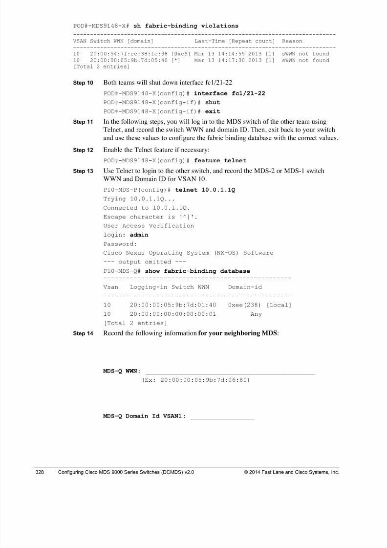
8/18/2019 FL_DCMDS_2.0.3_LG(1).pdf
http://slidepdf.com/reader/full/fldcmds203lg1pdf 328/482
328 Configuring Cisco MDS 9000 Series Switches (DCMDS) v2.0 © 2014 Fast Lane and Cisco Systems, Inc.
POD#-MDS9148-X# sh fabric-binding violations
------------------------------------------------------------------------------VSAN Switch WWN [domain] Last-Time [Repeat count] Reason------------------------------------------------------------------------------10 20:00:54:7f:ee:38:fc:38 [0xc9] Mar 13 14:14:55 2013 [1] sWWN not found10 20:00:00:05:9b:7d:05:40 [*] Mar 13 14:17:30 2013 [1] sWWN not found[Total 2 entries]
Step 10 Both teams will shut down interface fc1/21-22
POD#-MDS9148-X(config)# interface fc1/21-22 POD#-MDS9148-X(config-if)# shut
POD#-MDS9148-X(config-if)# exit
Step 11 In the following steps, you will log in to the MDS switch of the other team using
Telnet, and record the switch WWN and domain ID. Then, exit back to your switch
and use these values to configure the fabric binding database with the correct values.
Step 12 Enable the Telnet feature if necessary:
POD#-MDS9148-X(config)# feature telnet
Step 13 Use Telnet to login to the other switch, and record the MDS-2 or MDS-1 switch
WWN and Domain ID for VSAN 10.
P10-MDS-P(config)# telnet 10.0.1.1Q Trying 10.0.1.1Q...
Connected to 10.0.1.1Q.
Escape character is '^]'.
User Access Verification
login: admin
Password:
Cisco Nexus Operating System (NX-OS) Software
--- output omitted ---
P10-MDS-Q# show fabric-binding database --------------------------------------------------
Vsan Logging-in Switch WWN Domain-id--------------------------------------------------
10 20:00:00:05:9b:7d:01:40 0xee(238) [Local]
10 20:00:00:00:00:00:00:01 Any
[Total 2 entries]
Step 14 Record the following information for your neighboring MDS:
MDS-Q WWN: _____________________________________________
(Ex: 20:00:00:05:9b:7d:06:80)
MDS-Q Domain Id VSAN1: _________________
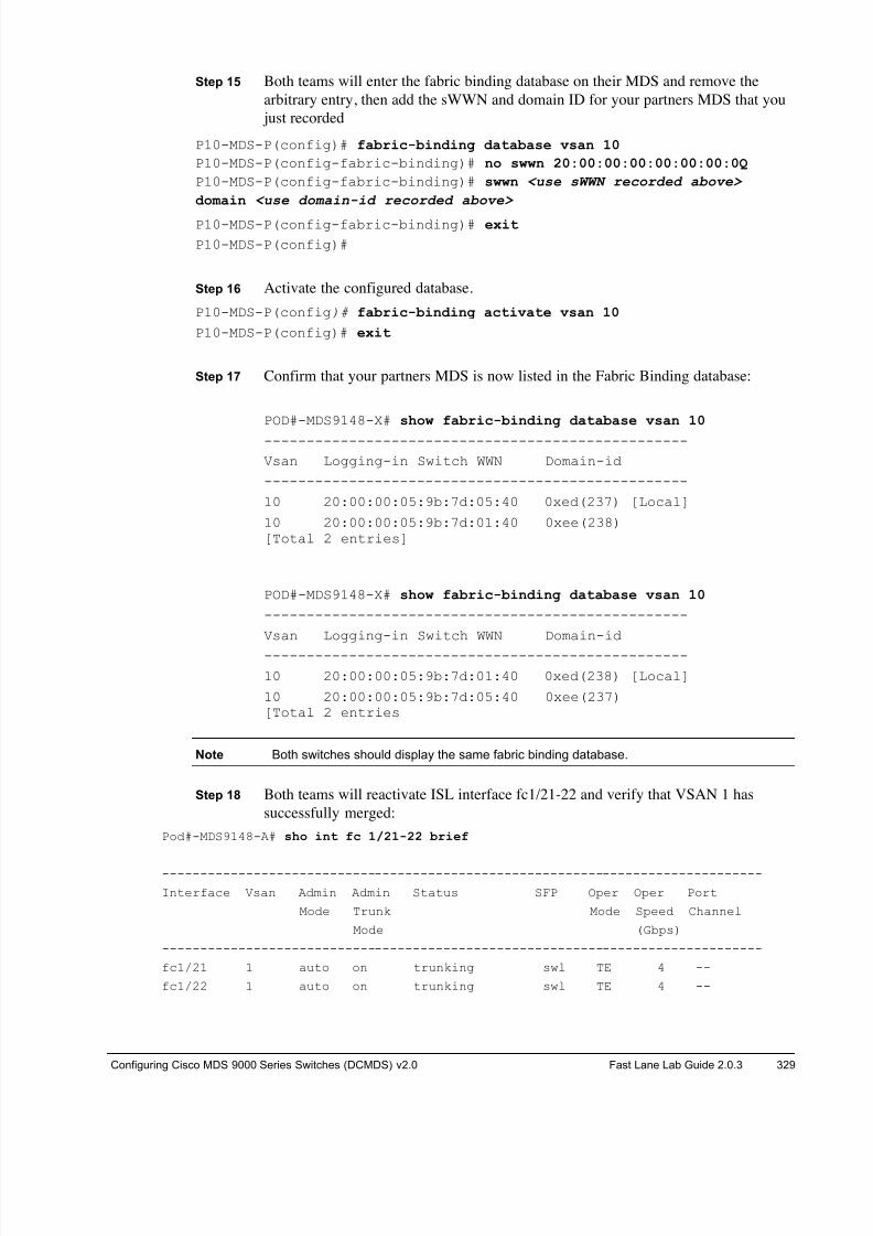
8/18/2019 FL_DCMDS_2.0.3_LG(1).pdf
http://slidepdf.com/reader/full/fldcmds203lg1pdf 329/482
Configuring Cisco MDS 9000 Series Switches (DCMDS) v2.0 Fast Lane Lab Guide 2.0.3 329
Step 15 Both teams will enter the fabric binding database on their MDS and remove the
arbitrary entry, then add the sWWN and domain ID for your partners MDS that you
just recorded
P10-MDS-P(config)# fabric-binding database vsan 10
P10-MDS-P(config-fabric-binding)# no swwn 20:00:00:00:00:00:00:0Q
P10-MDS-P(config-fabric-binding)# swwn <use sWWN recorded above>
domain <use domain-id recorded above>
P10-MDS-P(config-fabric-binding)# exit
P10-MDS-P(config)#
Step 16 Activate the configured database.
P10-MDS-P(config)# fabric-binding activate vsan 10
P10-MDS-P(config)# exit
Step 17 Confirm that your partners MDS is now listed in the Fabric Binding database:
POD#-MDS9148-X# show fabric-binding database vsan 10
--------------------------------------------------
Vsan Logging-in Switch WWN Domain-id
--------------------------------------------------
10 20:00:00:05:9b:7d:05:40 0xed(237) [Local]
10 20:00:00:05:9b:7d:01:40 0xee(238)[Total 2 entries]
POD#-MDS9148-X# show fabric-binding database vsan 10
--------------------------------------------------
Vsan Logging-in Switch WWN Domain-id
--------------------------------------------------
10 20:00:00:05:9b:7d:01:40 0xed(238) [Local]
10 20:00:00:05:9b:7d:05:40 0xee(237)[Total 2 entries
Note Both switches should display the same fabric binding database.
Step 18 Both teams will reactivate ISL interface fc1/21-22 and verify that VSAN 1 has
successfully merged:
Pod#-MDS9148-A# sho int fc 1/21-22 brief
-------------------------------------------------------------------------------
Interface Vsan Admin Admin Status SFP Oper Oper Port
Mode Trunk Mode Speed Channel
Mode (Gbps)
-------------------------------------------------------------------------------
fc1/21 1 auto on trunking swl TE 4 --
fc1/22 1 auto on trunking swl TE 4 --
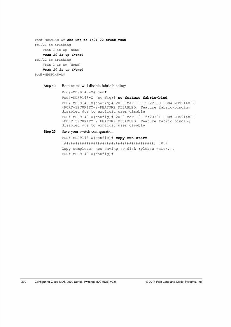
8/18/2019 FL_DCMDS_2.0.3_LG(1).pdf
http://slidepdf.com/reader/full/fldcmds203lg1pdf 330/482
330 Configuring Cisco MDS 9000 Series Switches (DCMDS) v2.0 © 2014 Fast Lane and Cisco Systems, Inc.
Pod#-MDS9148-A# sho int fc 1/21-22 trunk vsan
fc1/21 is trunking
Vsan 1 is up (None)
Vsan 10 is up (None)
fc1/22 is trunking
Vsan 1 is up (None)
Vsan 10 is up (None)
Pod#-MDS9148-A#
Step 19 Both teams will disable fabric binding:
Pod#-MDS9148-X# conf
Pod#-MDS9148-X (config)# no feature fabric-bind
POD#-MDS9148-X(config)# 2013 Mar 13 15:22:59 POD#-MDS9148-X%PORT-SECURITY-2-FEATURE_DISABLED: Feature fabric-bindingdisabled due to explicit user disable
POD#-MDS9148-X(config)# 2013 Mar 13 15:23:01 POD#-MDS9148-X%PORT-SECURITY-2-FEATURE_DISABLED: Feature fabric-bindingdisabled due to explicit user disable
Step 20 Save your switch configuration.
POD#-MDS9148-X(config)# copy run start
[########################################] 100%
Copy complete, now saving to disk (please wait)...
POD#-MDS9148-X(config)#
8/18/2019 FL_DCMDS_2.0.3_LG(1).pdf
http://slidepdf.com/reader/full/fldcmds203lg1pdf 331/482
Configuring Cisco MDS 9000 Series Switches (DCMDS) v2.0 Fast Lane Lab Guide 2.0.3 331
Task 4: Implement DH-CHAP
In this task, you will use the GUI to implement DH-CHAP authentication.
Activity Procedure
Complete these steps:
Note Team A will configure MDS-1, and Team B will configure MDS-2. However, the following
procedure requires cooperation and synchronization between the two teams. If you areworking alone, you will configure both Pod#-MDS9148-X switches.
Step 1 Verify that the ISL interface on fc1/21-22 is up and trunking.
Pod#-MDS9148-A# sho int fc 1/21-22 brief
--------------------------------------------------------------------------
Interface Vsan Admin Admin Status SFP Oper Oper Port
Mode Trunk Mode Speed Ch.
Mode (Gbps)
--------------------------------------------------------------------------
fc1/21 1 auto on trunking swl TE 4 --
fc1/22 1 auto on trunking swl TE 4 --
Pod#-MDS9148-A# sho int fc 1/21-22 trunk vsan
fc1/21 is trunking
Vsan 1 is up (None)
Vsan 10 is up (None)
fc1/22 is trunking
Vsan 1 is up (None)
Vsan 10 is up (None)
Pod#-MDS9148-A#
Step 2 Open Device Manager for your Switch
Step 3 Both teams will choose Admin > Feature Control.
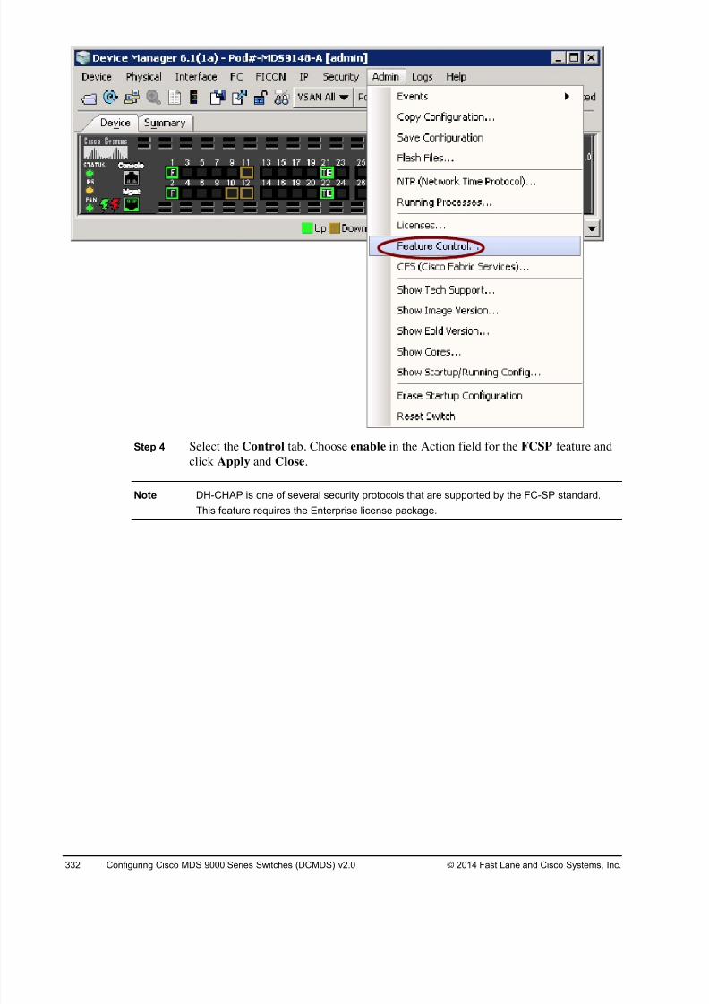
8/18/2019 FL_DCMDS_2.0.3_LG(1).pdf
http://slidepdf.com/reader/full/fldcmds203lg1pdf 332/482
332 Configuring Cisco MDS 9000 Series Switches (DCMDS) v2.0 © 2014 Fast Lane and Cisco Systems, Inc.
Step 4 Select the Control tab. Choose enable in the Action field for the FCSP feature and
click Apply and Close.
Note DH-CHAP is one of several security protocols that are supported by the FC-SP standard.
This feature requires the Enterprise license package.
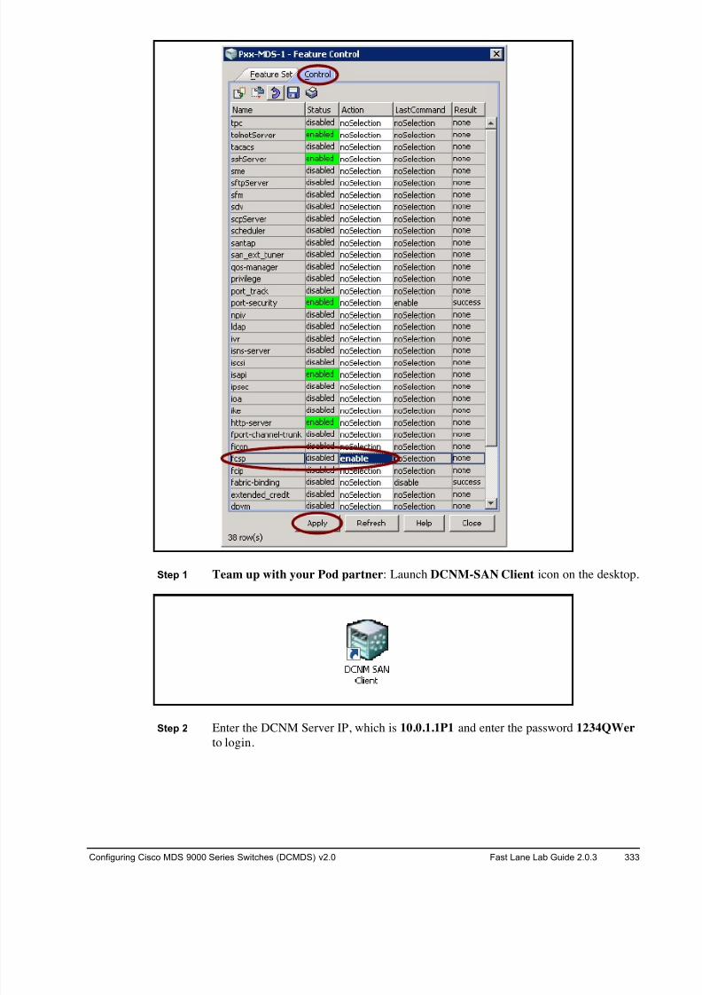
8/18/2019 FL_DCMDS_2.0.3_LG(1).pdf
http://slidepdf.com/reader/full/fldcmds203lg1pdf 333/482
Configuring Cisco MDS 9000 Series Switches (DCMDS) v2.0 Fast Lane Lab Guide 2.0.3 333
Step 1 Team up with your Pod partner: Launch DCNM-SAN Client icon on the desktop.
Step 2 Enter the DCNM Server IP, which is 10.0.1.1P1 and enter the password 1234QWer
to login.
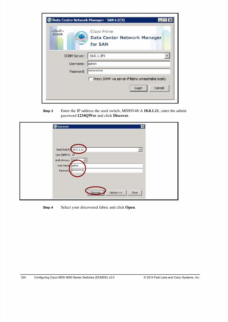
8/18/2019 FL_DCMDS_2.0.3_LG(1).pdf
http://slidepdf.com/reader/full/fldcmds203lg1pdf 334/482
334 Configuring Cisco MDS 9000 Series Switches (DCMDS) v2.0 © 2014 Fast Lane and Cisco Systems, Inc.
Step 3Enter the IP address the seed switch, MDS9148-A 10.0.1.11, enter the adminpassword 1234QWer and click Discover.
Step 4 Select your discovered fabric and click Open.
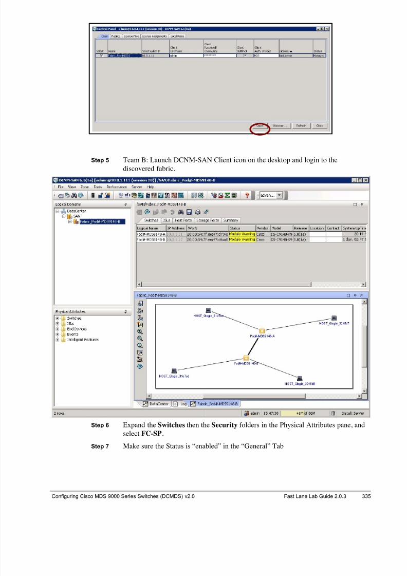
8/18/2019 FL_DCMDS_2.0.3_LG(1).pdf
http://slidepdf.com/reader/full/fldcmds203lg1pdf 335/482
Configuring Cisco MDS 9000 Series Switches (DCMDS) v2.0 Fast Lane Lab Guide 2.0.3 335
Step 5 Team B: Launch DCNM-SAN Client icon on the desktop and login to the
discovered fabric.
Step 6 Expand the Switches then the Security folders in the Physical Attributes pane, and
select FC-SP.
Step 7 Make sure the Status is “enabled” in the “General” Tab
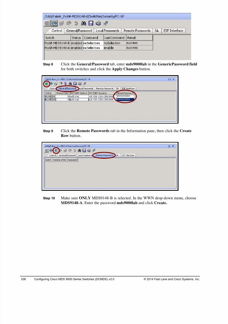
8/18/2019 FL_DCMDS_2.0.3_LG(1).pdf
http://slidepdf.com/reader/full/fldcmds203lg1pdf 336/482
336 Configuring Cisco MDS 9000 Series Switches (DCMDS) v2.0 © 2014 Fast Lane and Cisco Systems, Inc.
Step 8 Click the General/Password tab, enter mds9000lab in the GenericPassword field
for both switches and click the Apply Changes button.
Step 9 Click the Remote Passwords tab in the Information pane, then click the Create
Row button.
Step 10 Make sure ONLY MDS9148-B is selected. In the WWN drop-down menu, choose
MDS9148-A. Enter the password mds9000lab and click Create.
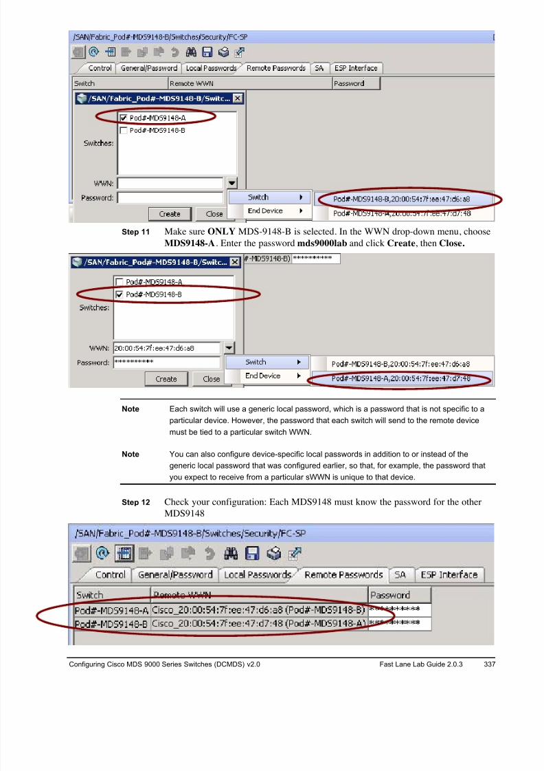
8/18/2019 FL_DCMDS_2.0.3_LG(1).pdf
http://slidepdf.com/reader/full/fldcmds203lg1pdf 337/482
Configuring Cisco MDS 9000 Series Switches (DCMDS) v2.0 Fast Lane Lab Guide 2.0.3 337
Step 11 Make sure ONLY MDS-9148-B is selected. In the WWN drop-down menu, choose
MDS9148-A. Enter the password mds9000lab and click Create, then Close.
Note Each switch will use a generic local password, which is a password that is not specific to a
particular device. However, the password that each switch will send to the remote device
must be tied to a particular switch WWN.
Note You can also configure device-specific local passwords in addition to or instead of the
generic local password that was configured earlier, so that, for example, the password that
you expect to receive from a particular sWWN is unique to that device.
Step 12 Check your configuration: Each MDS9148 must know the password for the other
MDS9148
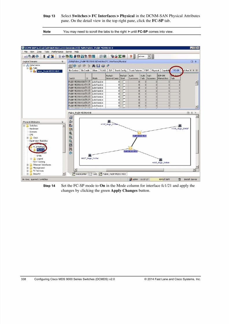
8/18/2019 FL_DCMDS_2.0.3_LG(1).pdf
http://slidepdf.com/reader/full/fldcmds203lg1pdf 338/482
338 Configuring Cisco MDS 9000 Series Switches (DCMDS) v2.0 © 2014 Fast Lane and Cisco Systems, Inc.
Step 13 Select Switches > FC Interfaces > Physical in the DCNM-SAN Physical Attributes
pane. On the detail view in the top right pane, click the FC-SP tab.
Note You may need to scroll the tabs to the right > until FC-SP comes into view.
Step 14 Set the FC-SP mode to On in the Mode column for interface fc1/21 and apply the
changes by clicking the green Apply Changes button.
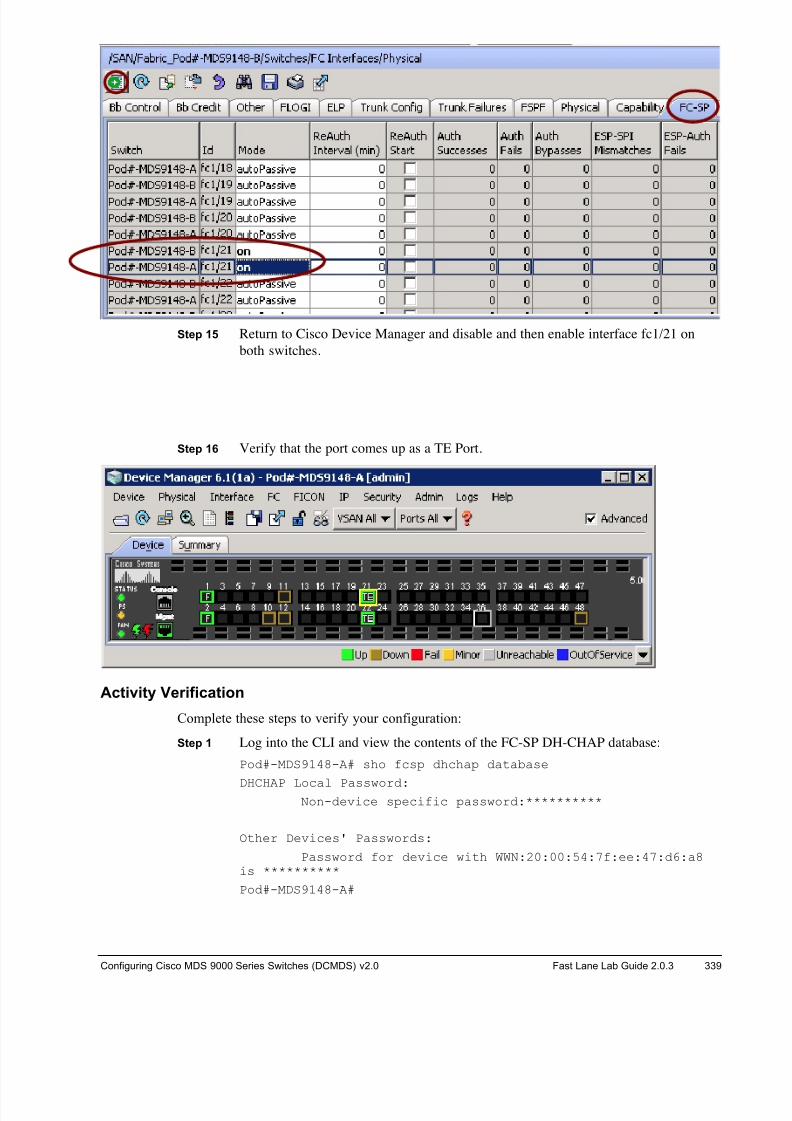
8/18/2019 FL_DCMDS_2.0.3_LG(1).pdf
http://slidepdf.com/reader/full/fldcmds203lg1pdf 339/482
Configuring Cisco MDS 9000 Series Switches (DCMDS) v2.0 Fast Lane Lab Guide 2.0.3 339
Step 15 Return to Cisco Device Manager and disable and then enable interface fc1/21 on
both switches.
Step 16 Verify that the port comes up as a TE Port.
Activity Verification
Complete these steps to verify your configuration:
Step 1 Log into the CLI and view the contents of the FC-SP DH-CHAP database:
Pod#-MDS9148-A# sho fcsp dhchap database
DHCHAP Local Password:Non-device specific password:**********
Other Devices' Passwords:
Password for device with WWN:20:00:54:7f:ee:47:d6:a8is **********
Pod#-MDS9148-A#
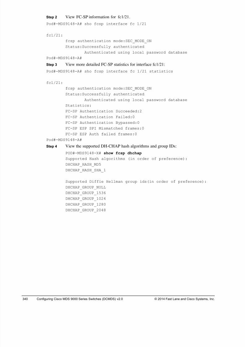
8/18/2019 FL_DCMDS_2.0.3_LG(1).pdf
http://slidepdf.com/reader/full/fldcmds203lg1pdf 340/482
340 Configuring Cisco MDS 9000 Series Switches (DCMDS) v2.0 © 2014 Fast Lane and Cisco Systems, Inc.
Step 2 View FC-SP information for fc1/21.
Pod#-MDS9148-A# sho fcsp interface fc 1/21
fc1/21:
fcsp authentication mode:SEC_MODE_ON
Status:Successfully authenticated
Authenticated using local password database
Pod#-MDS9148-A#
Step 3 View more detailed FC-SP statistics for interface fc1/21:
Pod#-MDS9148-A# sho fcsp interface fc 1/21 statistics
fc1/21:
fcsp authentication mode:SEC_MODE_ON
Status:Successfully authenticated
Authenticated using local password database
Statistics:
FC-SP Authentication Succeeded:2
FC-SP Authentication Failed:0
FC-SP Authentication Bypassed:0
FC-SP ESP SPI Mismatched frames:0
FC-SP ESP Auth failed frames:0
Pod#-MDS9148-A#
Step 4 View the supported DH-CHAP hash algorithms and group IDs:
POD#-MDS9148-X# show fcsp dhchap
Supported Hash algorithms (in order of preference):
DHCHAP_HASH_MD5
DHCHAP_HASH_SHA_1
Supported Diffie Hellman group ids(in order of preference):DHCHAP_GROUP_NULL
DHCHAP_GROUP_1536
DHCHAP_GROUP_1024
DHCHAP_GROUP_1280
DHCHAP_GROUP_2048
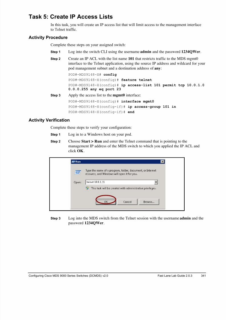
8/18/2019 FL_DCMDS_2.0.3_LG(1).pdf
http://slidepdf.com/reader/full/fldcmds203lg1pdf 341/482
Configuring Cisco MDS 9000 Series Switches (DCMDS) v2.0 Fast Lane Lab Guide 2.0.3 341
Task 5: Create IP Access Lists
In this task, you will create an IP access list that will limit access to the management interface
to Telnet traffic.
Activity Procedure
Complete these steps on your assigned switch:
Step 1 Log into the switch CLI using the username admin and the password 1234QWer.
Step 2 Create an IP ACL with the list name 101 that restricts traffic to the MDS mgmt0
interface to the Telnet application, using the source IP address and wildcard for your
pod management subnet and a destination address of any:
POD#-MDS9148-X# config
POD#-MDS9148-X(config)# feature telnet
POD#-MDS9148-X(config)# ip access-list 101 permit tcp 10.0.1.00.0.0.255 any eq port 23
Step 3 Apply the access list to the mgmt0 interface:
POD#-MDS9148-X(config)# interface mgmt0
POD#-MDS9148-X(config-if)# ip access-group 101 in
POD#-MDS9148-X(config-if)# end
Activity Verification
Complete these steps to verify your configuration:
Step 1 Log in to a Windows host on your pod.
Step 2 Choose Start > Run and enter the Telnet command that is pointing to the
management IP address of the MDS switch to which you applied the IP ACL and
click OK.
Step 3 Log into the MDS switch from the Telnet session with the username admin and the
password 1234QWer.
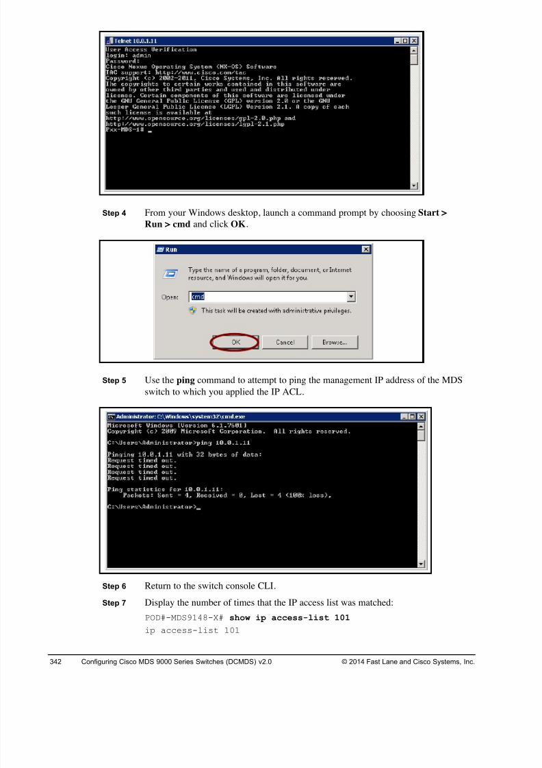
8/18/2019 FL_DCMDS_2.0.3_LG(1).pdf
http://slidepdf.com/reader/full/fldcmds203lg1pdf 342/482
342 Configuring Cisco MDS 9000 Series Switches (DCMDS) v2.0 © 2014 Fast Lane and Cisco Systems, Inc.
Step 4 From your Windows desktop, launch a command prompt by choosing Start >
Run > cmd and click OK.
Step 5 Use the ping command to attempt to ping the management IP address of the MDS
switch to which you applied the IP ACL.
Step 6 Return to the switch console CLI.
Step 7 Display the number of times that the IP access list was matched:
POD#-MDS9148-X# show ip access-list 101
ip access-list 101
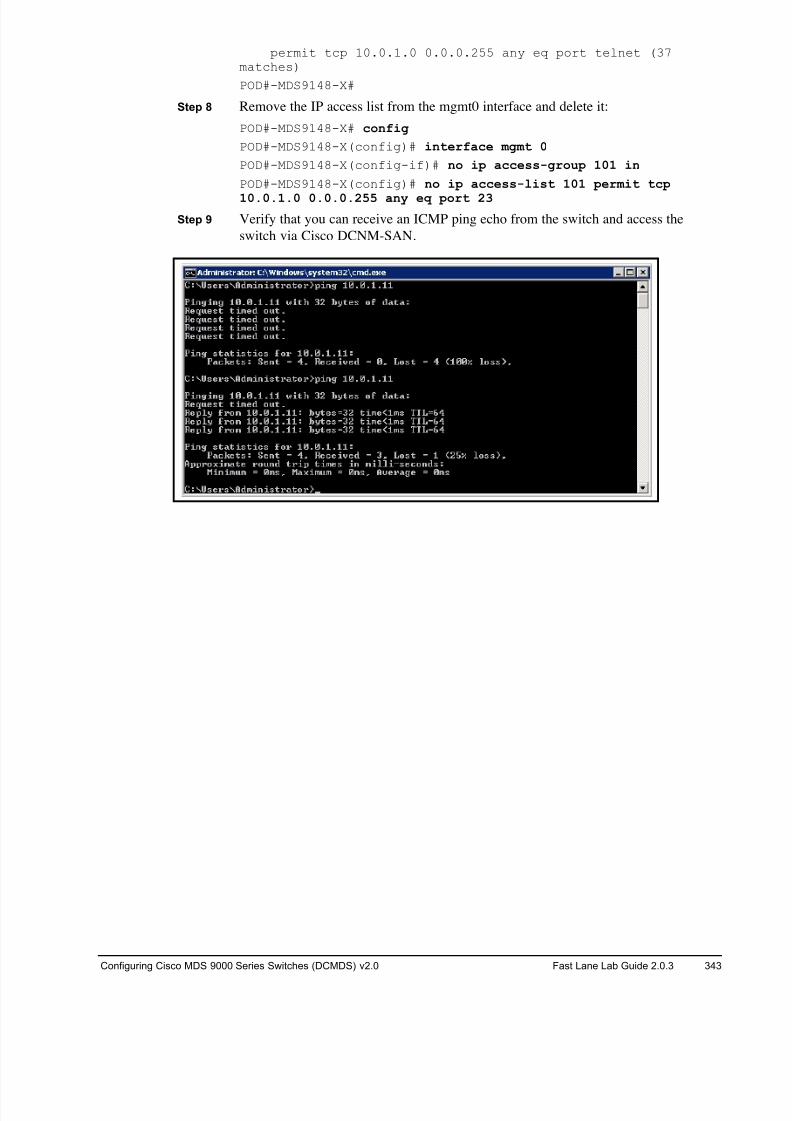
8/18/2019 FL_DCMDS_2.0.3_LG(1).pdf
http://slidepdf.com/reader/full/fldcmds203lg1pdf 343/482
Configuring Cisco MDS 9000 Series Switches (DCMDS) v2.0 Fast Lane Lab Guide 2.0.3 343
permit tcp 10.0.1.0 0.0.0.255 any eq port telnet (37matches)
POD#-MDS9148-X#
Step 8 Remove the IP access list from the mgmt0 interface and delete it:
POD#-MDS9148-X# config
POD#-MDS9148-X(config)# interface mgmt 0
POD#-MDS9148-X(config-if)# no ip access-group 101 in
POD#-MDS9148-X(config)# no ip access-list 101 permit tcp
10.0.1.0 0.0.0.255 any eq port 23
Step 9 Verify that you can receive an ICMP ping echo from the switch and access the
switch via Cisco DCNM-SAN.
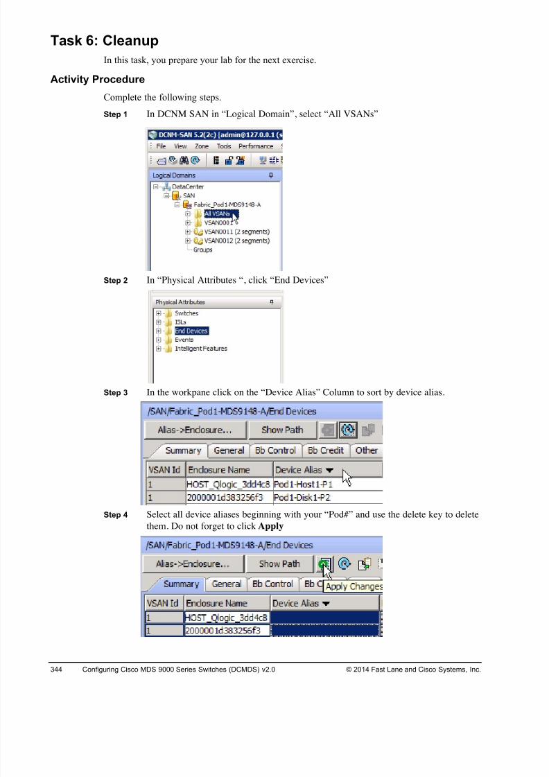
8/18/2019 FL_DCMDS_2.0.3_LG(1).pdf
http://slidepdf.com/reader/full/fldcmds203lg1pdf 344/482
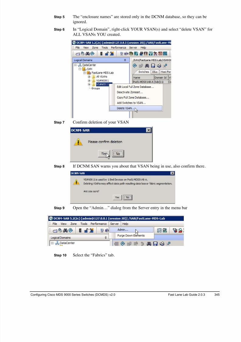
8/18/2019 FL_DCMDS_2.0.3_LG(1).pdf
http://slidepdf.com/reader/full/fldcmds203lg1pdf 345/482
Configuring Cisco MDS 9000 Series Switches (DCMDS) v2.0 Fast Lane Lab Guide 2.0.3 345
Step 5 The “enclosure names” are stored only in the DCNM database, so they can be
ignored.
Step 6 In “Logical Domain”, right-click YOUR VSAN(s) and select “delete VSAN” for
ALL VSANs YOU created.
Step 7 Confirm deletion of your VSAN
Step 8 If DCNM SAN warns you about that VSAN being in use, also confirm there.
Step 9 Open the “Admin…” dialog from the Server entry in the menu bar
Step 10 Select the “Fabrics” tab.
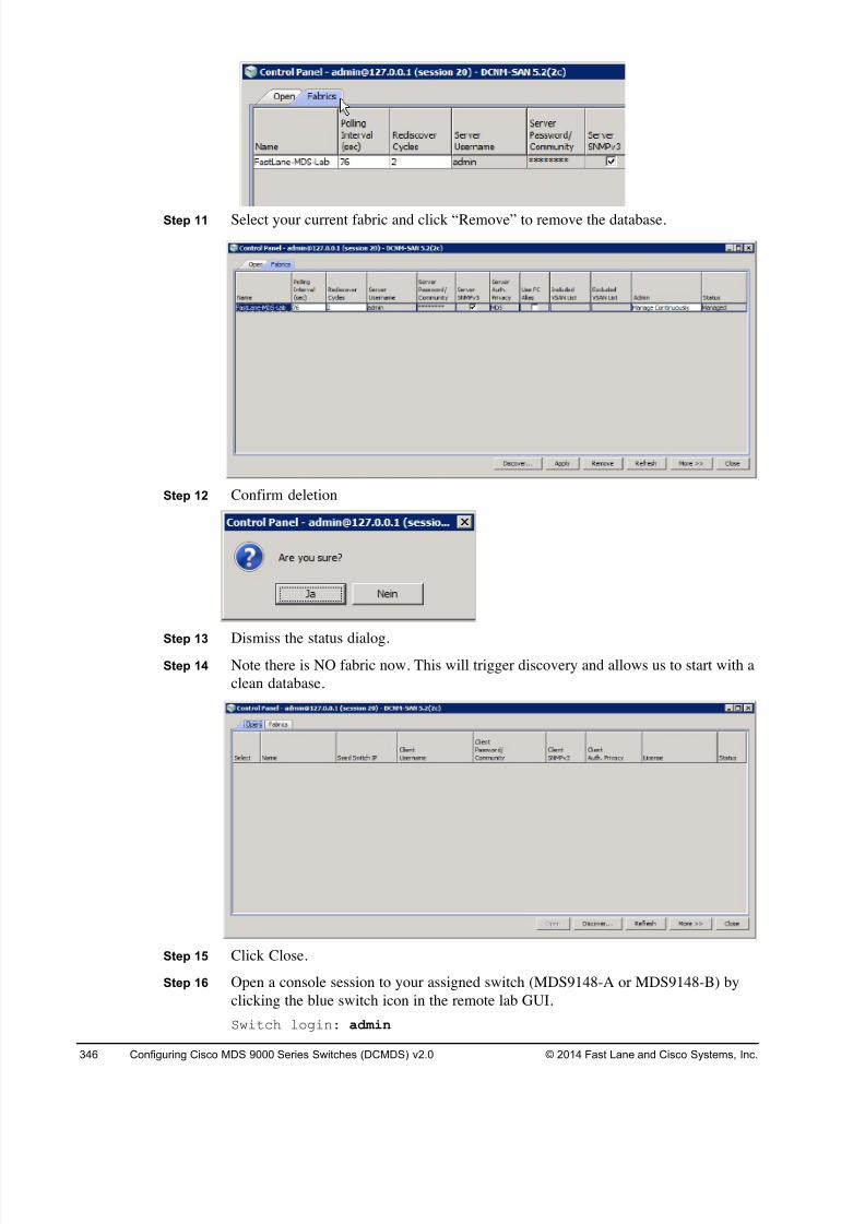
8/18/2019 FL_DCMDS_2.0.3_LG(1).pdf
http://slidepdf.com/reader/full/fldcmds203lg1pdf 346/482
346 Configuring Cisco MDS 9000 Series Switches (DCMDS) v2.0 © 2014 Fast Lane and Cisco Systems, Inc.
Step 11 Select your current fabric and click “Remove” to remove the database.
Step 12 Confirm deletion
Step 13 Dismiss the status dialog.Step 14 Note there is NO fabric now. This will trigger discovery and allows us to start with a
clean database.
Step 15 Click Close.
Step 16 Open a console session to your assigned switch (MDS9148-A or MDS9148-B) by
clicking the blue switch icon in the remote lab GUI.
Switch login: admin
8/18/2019 FL_DCMDS_2.0.3_LG(1).pdf
http://slidepdf.com/reader/full/fldcmds203lg1pdf 347/482
Configuring Cisco MDS 9000 Series Switches (DCMDS) v2.0 Fast Lane Lab Guide 2.0.3 347
Password: 1234QWer
Step 17 Clear the current startup configuration ON YOUR 9148s ONLY, DO NOT CLEAR
THE CORE 9222is!!! .
# write erase
The following message is displayed:
Warning: This command will erase the startup-configuration.
Do you wish to proceed anyway? [y/n] [N]
Type y to proceed.
Step 18 Reboot the 9148 switch.
# reload
This command will reboot the system. (y/n)?
Type y to proceed.
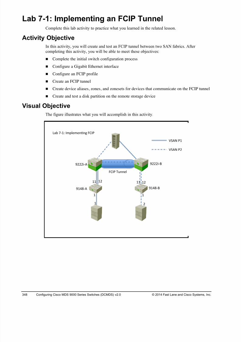
8/18/2019 FL_DCMDS_2.0.3_LG(1).pdf
http://slidepdf.com/reader/full/fldcmds203lg1pdf 348/482
348 Configuring Cisco MDS 9000 Series Switches (DCMDS) v2.0 © 2014 Fast Lane and Cisco Systems, Inc.
Lab 7-1: Implementing an FCIP Tunnel Complete this lab activity to practice what you learned in the related lesson.
Activity Objective
In this activity, you will create and test an FCIP tunnel between two SAN fabrics. After
completing this activity, you will be able to meet these objectives:
! Complete the initial switch configuration process
! Configure a Gigabit Ethernet interface
! Configure an FCIP profile
! Create an FCIP tunnel
! Create device aliases, zones, and zonesets for devices that communicate on the FCIP tunnel
! Create and test a disk partition on the remote storage device
Visual Objective
The figure illustrates what you will accomplish in this activity.
! !
!# !! !#!!
! #
$!%&'( $!%&')
$###*'( $###*')
+,- .'!/ 01234145657 890:
;<(= :!
;<(= :#
890: >?5543
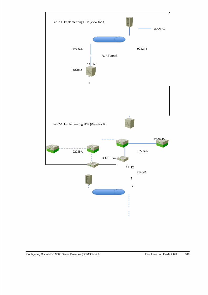
8/18/2019 FL_DCMDS_2.0.3_LG(1).pdf
http://slidepdf.com/reader/full/fldcmds203lg1pdf 349/482
Configuring Cisco MDS 9000 Series Switches (DCMDS) v2.0 Fast Lane Lab Guide 2.0.3 349
!
!#!!
!
$!%&'(
$###)'( $###)'*
+,- .'!/ 01234145657 890: ;<)4= >?@ (A
890: BC5543
<D(E :!
!
!! !#
#
$!%&'(
$###)'* $###)'(
+,- .'!/ 01234145657 890: ;<)4= >?@ (A
890: BC5543
<D*E :#
8/18/2019 FL_DCMDS_2.0.3_LG(1).pdf
http://slidepdf.com/reader/full/fldcmds203lg1pdf 350/482
350 Configuring Cisco MDS 9000 Series Switches (DCMDS) v2.0 © 2014 Fast Lane and Cisco Systems, Inc.
Required Resources
These are the resources and equipment required to complete this activity:
! Two MDS 9000 Fibre Channel switches with IPS modules or integrated Gigabit Ethernet
ports
! Two Windows servers, each with a Fibre Channel (FC) HBA
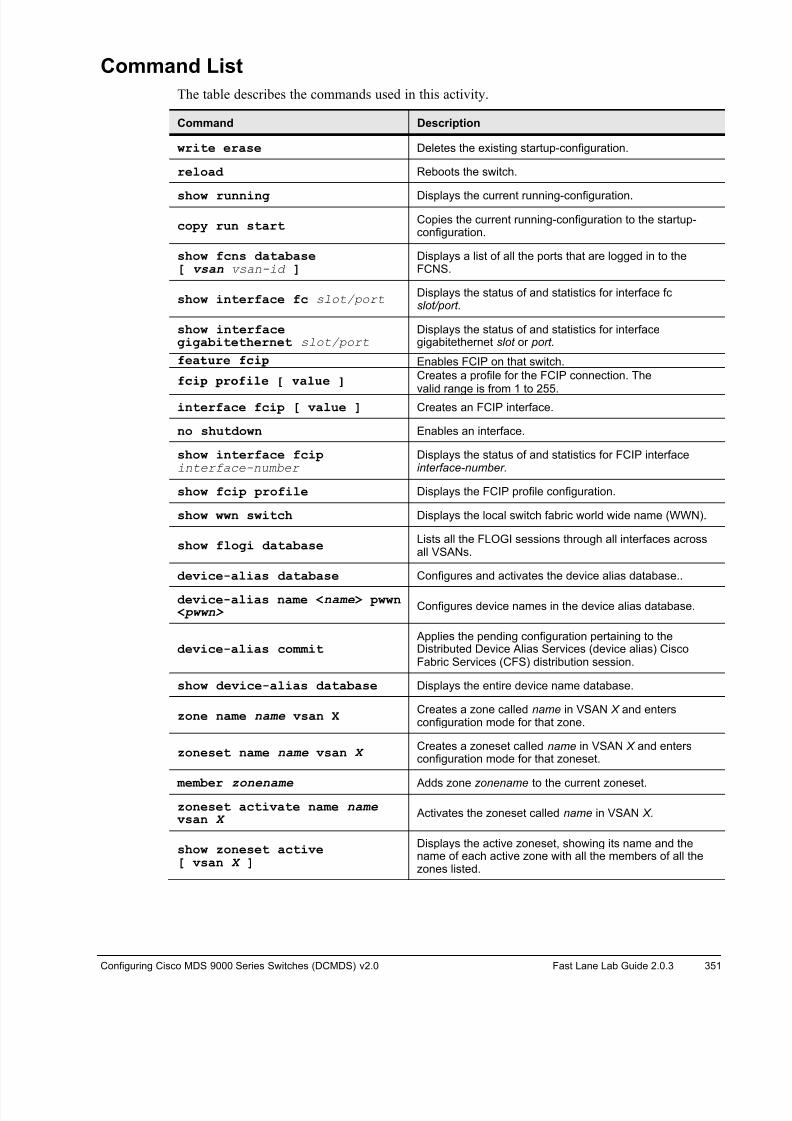
8/18/2019 FL_DCMDS_2.0.3_LG(1).pdf
http://slidepdf.com/reader/full/fldcmds203lg1pdf 351/482
Configuring Cisco MDS 9000 Series Switches (DCMDS) v2.0 Fast Lane Lab Guide 2.0.3 351
Command List
The table describes the commands used in this activity.
Command Description
write erase Deletes the existing startup-configuration.
reload Reboots the switch.
show running Displays the current running-configuration.
copy run startCopies the current running-configuration to the startup-configuration.
show fcns database[ vsan vsan-id ]
Displays a list of all the ports that are logged in to theFCNS.
show interface fc slot/port Displays the status of and statistics for interface fc slot/port.
show interfacegigabitethernet slot/port
Displays the status of and statistics for interfacegigabitethernet slot or port.
feature fcip Enables FCIP on that switch.
fcip profile [ value ]Creates a profile for the FCIP connection. The
valid range is from 1 to 255.interface fcip [ value ] Creates an FCIP interface.
no shutdown Enables an interface.
show interface fcipinterface-number
Displays the status of and statistics for FCIP interfaceinterface-number.
show fcip profile Displays the FCIP profile configuration.
show wwn switch Displays the local switch fabric world wide name (WWN).
show flogi databaseLists all the FLOGI sessions through all interfaces acrossall VSANs.
device-alias database Configures and activates the device alias database..
device-alias name <name> pwwn < pwwn> Configures device names in the device alias database.
device-alias commit Applies the pending configuration pertaining to theDistributed Device Alias Services (device alias) CiscoFabric Services (CFS) distribution session.
show device-alias database Displays the entire device name database.
zone name name vsan X Creates a zone called name in VSAN X and entersconfiguration mode for that zone.
zoneset name name vsan X Creates a zoneset called name in VSAN X and entersconfiguration mode for that zoneset.
member zonename Adds zone zonename to the current zoneset.
zoneset activate name name vsan X Activates the zoneset called name in VSAN X.
show zoneset active[ vsan X ]
Displays the active zoneset, showing its name and thename of each active zone with all the members of all thezones listed.

8/18/2019 FL_DCMDS_2.0.3_LG(1).pdf
http://slidepdf.com/reader/full/fldcmds203lg1pdf 352/482
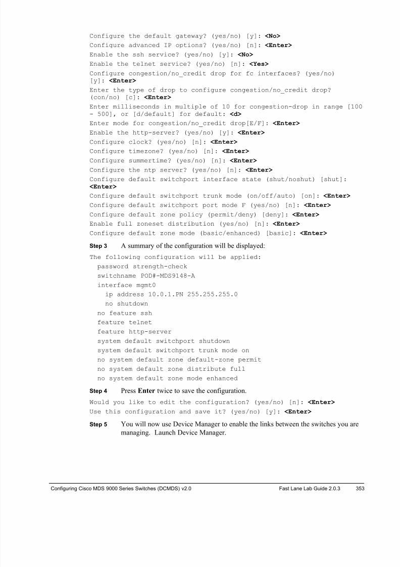
8/18/2019 FL_DCMDS_2.0.3_LG(1).pdf
http://slidepdf.com/reader/full/fldcmds203lg1pdf 353/482
Configuring Cisco MDS 9000 Series Switches (DCMDS) v2.0 Fast Lane Lab Guide 2.0.3 353
Configure the default gateway? (yes/no) [y]: <No>
Configure advanced IP options? (yes/no) [n]: <Enter>
Enable the ssh service? (yes/no) [y]: <No>
Enable the telnet service? (yes/no) [n]: <Yes>
Configure congestion/no_credit drop for fc interfaces? (yes/no)[y]: <Enter>
Enter the type of drop to configure congestion/no_credit drop?
(con/no) [c]: <Enter>Enter milliseconds in multiple of 10 for congestion-drop in range [100- 500], or [d/default] for default: <d>
Enter mode for congestion/no_credit drop[E/F]: <Enter>
Enable the http-server? (yes/no) [y]: <Enter>
Configure clock? (yes/no) [n]: <Enter>
Configure timezone? (yes/no) [n]: <Enter>
Configure summertime? (yes/no) [n]: <Enter>
Configure the ntp server? (yes/no) [n]: <Enter>
Configure default switchport interface state (shut/noshut) [shut]: <Enter>
Configure default switchport trunk mode (on/off/auto) [on]: <Enter> Configure default switchport port mode F (yes/no) [n]: <Enter>
Configure default zone policy (permit/deny) [deny]: <Enter>
Enable full zoneset distribution (yes/no) [n]: <Enter>
Configure default zone mode (basic/enhanced) [basic]: <Enter>
Step 3 A summary of the configuration will be displayed:
The following configuration will be applied:
password strength-check
switchname POD#-MDS9148-A
interface mgmt0
ip address 10.0.1.PN 255.255.255.0
no shutdown
no feature ssh
feature telnet
feature http-server
system default switchport shutdown
system default switchport trunk mode on
no system default zone default-zone permit
no system default zone distribute full
no system default zone mode enhanced
Step 4 Press Enter twice to save the configuration.
Would you like to edit the configuration? (yes/no) [n]: <Enter>
Use this configuration and save it? (yes/no) [y]: <Enter>
Step 5 You will now use Device Manager to enable the links between the switches you are
managing. Launch Device Manager.
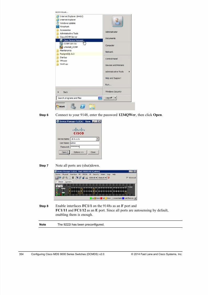
8/18/2019 FL_DCMDS_2.0.3_LG(1).pdf
http://slidepdf.com/reader/full/fldcmds203lg1pdf 354/482
354 Configuring Cisco MDS 9000 Series Switches (DCMDS) v2.0 © 2014 Fast Lane and Cisco Systems, Inc.
Step 6 Connect to your 9148, enter the password 1234QWer, then click Open.
Step 7 Note all ports are (shut)down.
Step 8 Enable interfaces FC1/1 on the 9148s as an F port andFC1/11 and FC1/12 as an E port. Since all ports are autosensing by default,
enabling them is enough.
Note The 9222i has been preconfigured.
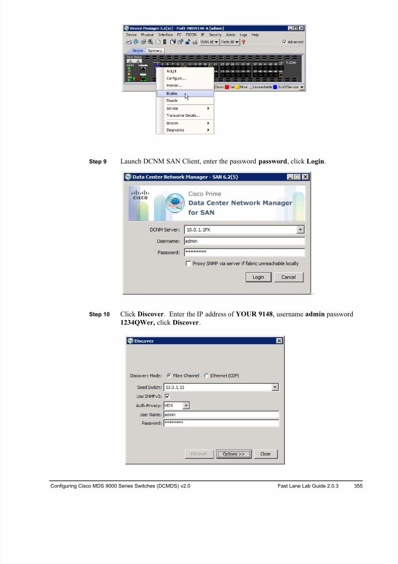
8/18/2019 FL_DCMDS_2.0.3_LG(1).pdf
http://slidepdf.com/reader/full/fldcmds203lg1pdf 355/482
Configuring Cisco MDS 9000 Series Switches (DCMDS) v2.0 Fast Lane Lab Guide 2.0.3 355
Step 9 Launch DCNM SAN Client, enter the password password, click Login.
Step 10 Click Discover. Enter the IP address of YOUR 9148, username admin password
1234QWer, click Discover.
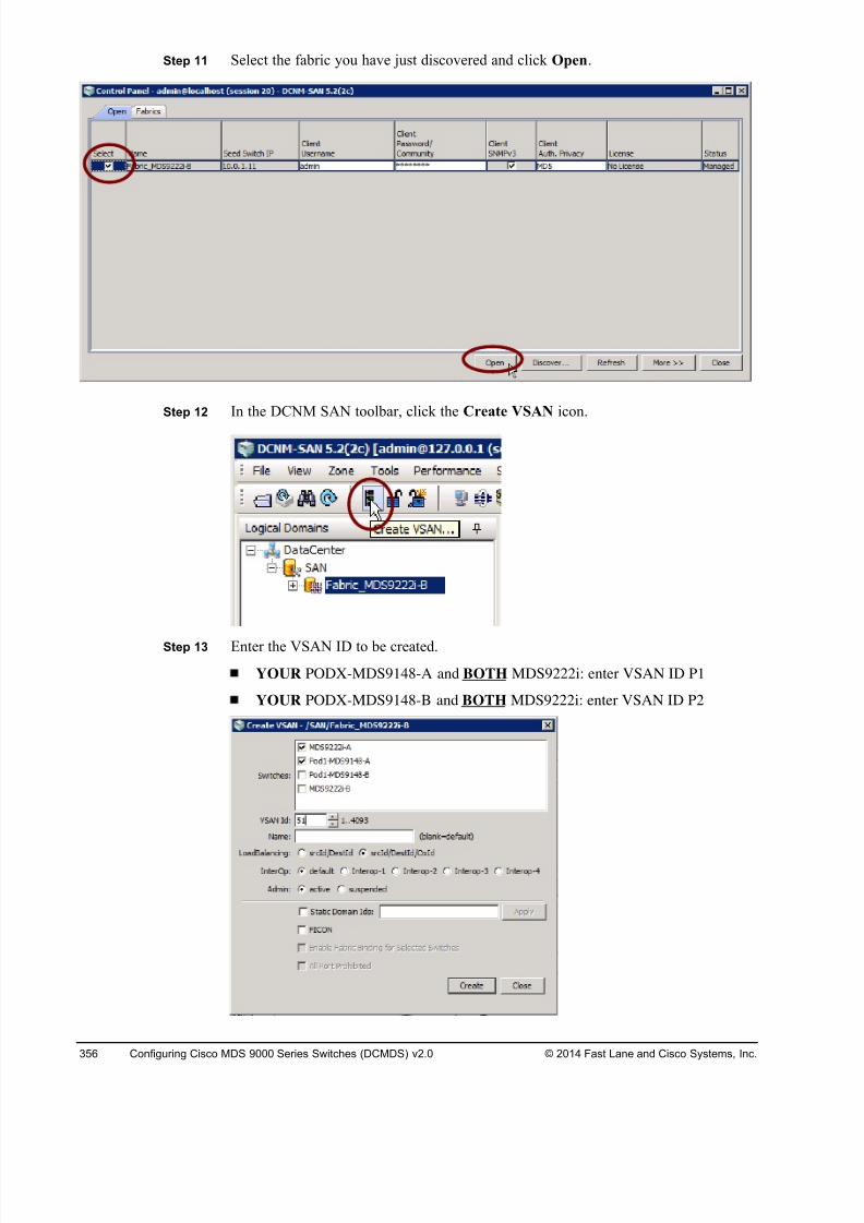
8/18/2019 FL_DCMDS_2.0.3_LG(1).pdf
http://slidepdf.com/reader/full/fldcmds203lg1pdf 356/482
356 Configuring Cisco MDS 9000 Series Switches (DCMDS) v2.0 © 2014 Fast Lane and Cisco Systems, Inc.
Step 11 Select the fabric you have just discovered and click Open.
Step 12 In the DCNM SAN toolbar, click the Create VSAN icon.
Step 13 Enter the VSAN ID to be created.
YOUR PODX-MDS9148-A and BOTH MDS9222i: enter VSAN ID P1
YOUR PODX-MDS9148-B and BOTH MDS9222i: enter VSAN ID P2
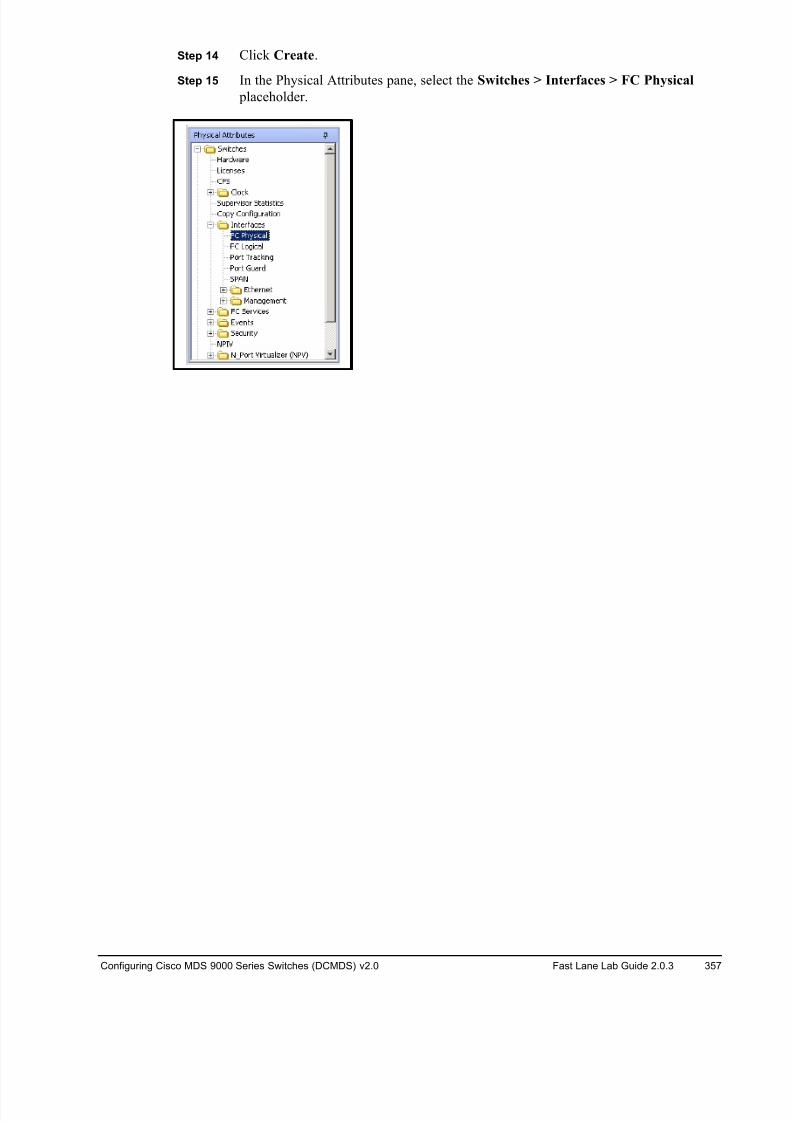
8/18/2019 FL_DCMDS_2.0.3_LG(1).pdf
http://slidepdf.com/reader/full/fldcmds203lg1pdf 357/482
Configuring Cisco MDS 9000 Series Switches (DCMDS) v2.0 Fast Lane Lab Guide 2.0.3 357
Step 14 Click Create.
Step 15 In the Physical Attributes pane, select the Switches > Interfaces > FC Physical
placeholder.
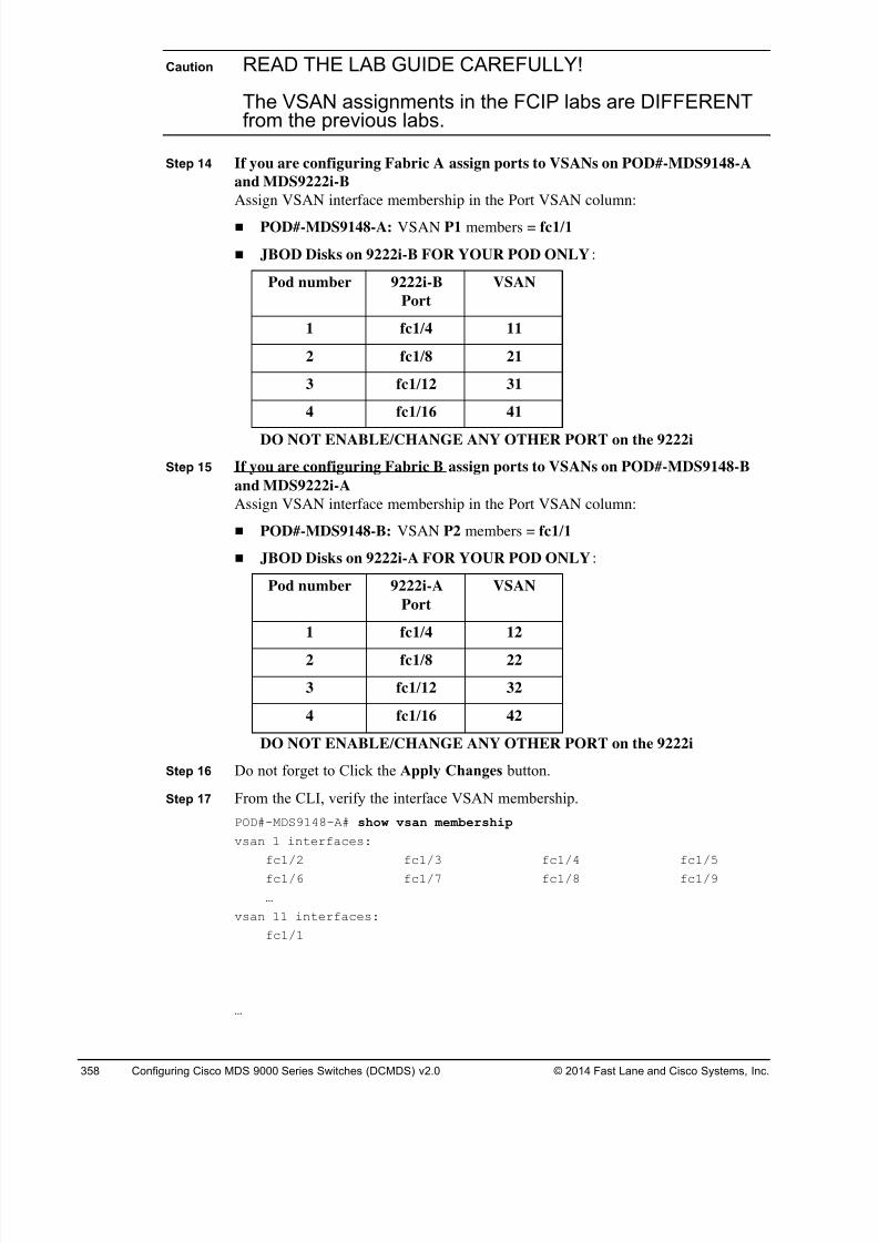
8/18/2019 FL_DCMDS_2.0.3_LG(1).pdf
http://slidepdf.com/reader/full/fldcmds203lg1pdf 358/482
358 Configuring Cisco MDS 9000 Series Switches (DCMDS) v2.0 © 2014 Fast Lane and Cisco Systems, Inc.
Caution READ THE LAB GUIDE CAREFULLY!
The VSAN assignments in the FCIP labs are DIFFERENTfrom the previous labs.
Step 14 If you are configuring Fabric A assign ports to VSANs on POD#-MDS9148-A
and MDS9222i-B
Assign VSAN interface membership in the Port VSAN column:
! POD#-MDS9148-A: VSAN P1 members = fc1/1
! JBOD Disks on 9222i-B FOR YOUR POD ONLY:
Pod number 9222i-B
Port
VSAN
1 fc1/4 11
2 fc1/8 21
3 fc1/12 31
4 fc1/16 41
DO NOT ENABLE/CHANGE ANY OTHER PORT on the 9222i
Step 15 If you are configuring Fabric B assign ports to VSANs on POD#-MDS9148-B
and MDS9222i-A
Assign VSAN interface membership in the Port VSAN column:
! POD#-MDS9148-B: VSAN P2 members = fc1/1
! JBOD Disks on 9222i-A FOR YOUR POD ONLY:
Pod number 9222i-A
Port
VSAN
1 fc1/4 12
2 fc1/8 22
3 fc1/12 32
4 fc1/16 42
DO NOT ENABLE/CHANGE ANY OTHER PORT on the 9222i
Step 16 Do not forget to Click the Apply Changes button.
Step 17 From the CLI, verify the interface VSAN membership.
POD#-MDS9148-A# show vsan membership
vsan 1 interfaces:
fc1/2 fc1/3 fc1/4 fc1/5
fc1/6 fc1/7 fc1/8 fc1/9
…
vsan 11 interfaces:
fc1/1
…
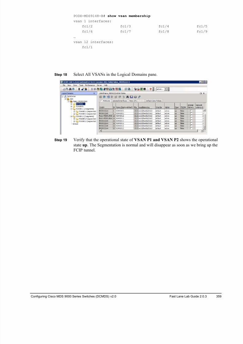
8/18/2019 FL_DCMDS_2.0.3_LG(1).pdf
http://slidepdf.com/reader/full/fldcmds203lg1pdf 359/482
Configuring Cisco MDS 9000 Series Switches (DCMDS) v2.0 Fast Lane Lab Guide 2.0.3 359
PODX-MDS9148-B# show vsan membership
vsan 1 interfaces:
fc1/2 fc1/3 fc1/4 fc1/5
fc1/6 fc1/7 fc1/8 fc1/9
…
vsan 12 interfaces:
fc1/1
Step 18 Select All VSANs in the Logical Domains pane.
Step 19 Verify that the operational state of VSAN P1 and VSAN P2 shows the operational
state up. The Segmentation is normal and will disappear as soon as we bring up the
FCIP tunnel.
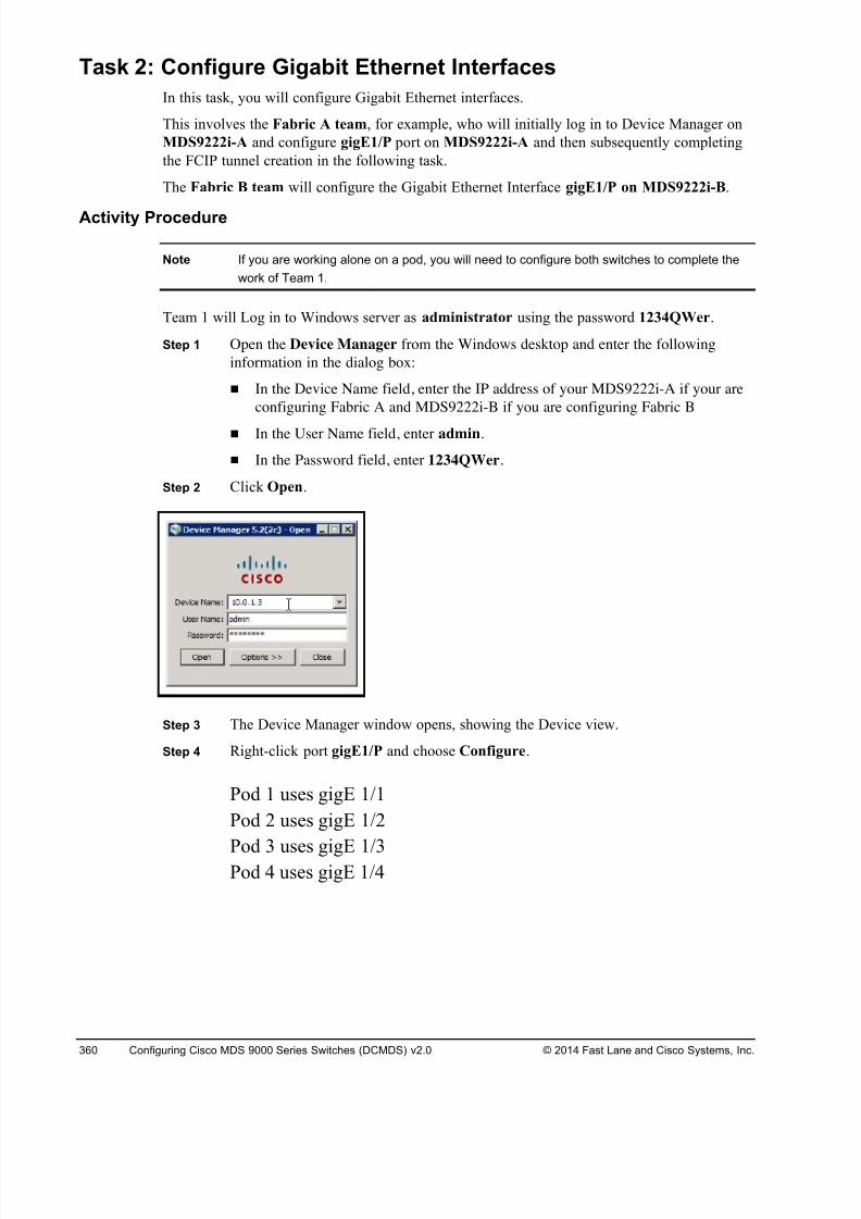
8/18/2019 FL_DCMDS_2.0.3_LG(1).pdf
http://slidepdf.com/reader/full/fldcmds203lg1pdf 360/482
360 Configuring Cisco MDS 9000 Series Switches (DCMDS) v2.0 © 2014 Fast Lane and Cisco Systems, Inc.
Task 2: Configure Gigabit Ethernet Interfaces
In this task, you will configure Gigabit Ethernet interfaces.
This involves the Fabric A team, for example, who will initially log in to Device Manager on
MDS9222i-A and configure gigE1/P port on MDS9222i-A and then subsequently completing
the FCIP tunnel creation in the following task.
The Fabric B team will configure the Gigabit Ethernet Interface gigE1/P on MDS9222i-B.
Activity Procedure
Note If you are working alone on a pod, you will need to configure both switches to complete the
work of Team 1.
Team 1 will Log in to Windows server as administrator using the password 1234QWer.
Step 1 Open the Device Manager from the Windows desktop and enter the following
information in the dialog box:
! In the Device Name field, enter the IP address of your MDS9222i-A if your are
configuring Fabric A and MDS9222i-B if you are configuring Fabric B
! In the User Name field, enter admin.
! In the Password field, enter 1234QWer.
Step 2 Click Open.
Step 3 The Device Manager window opens, showing the Device view.
Step 4 Right-click port gigE1/P and choose Configure.
Pod 1 uses gigE 1/1
Pod 2 uses gigE 1/2
Pod 3
uses gigE1/3
Pod 4 uses gigE 1/4
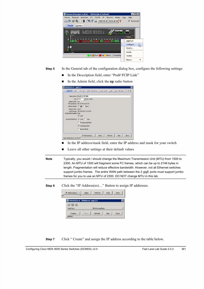
8/18/2019 FL_DCMDS_2.0.3_LG(1).pdf
http://slidepdf.com/reader/full/fldcmds203lg1pdf 361/482
Configuring Cisco MDS 9000 Series Switches (DCMDS) v2.0 Fast Lane Lab Guide 2.0.3 361
Step 5 In the General tab of the configuration dialog box, configure the following settings:
! In the Description field, enter “Pod# FCIP Link”
! In the Admin field, click the up radio button
! In the IP address/mask field, enter the IP address and mask for your switch
! Leave all other settings at their default values
Note Typically, you would / should change the Maximum Transmission Unit (MTU) from 1500 to
2300. An MTU of 1500 will fragment some FC frames, which can be up to 2148 bytes in
length. Fragmentation will reduce effective bandwidth. However, not all Ethernet switches
support jumbo frames. The entire WAN path between the 2 gigE ports must support jumbo
frames for you to use an MTU of 2300. DO NOT change MTU in this lab.
Step 6 Click the “IP Address(es)…” Button to assign IP addresses.
Step 7 Click “ Create” and assign the IP address according to the table below.
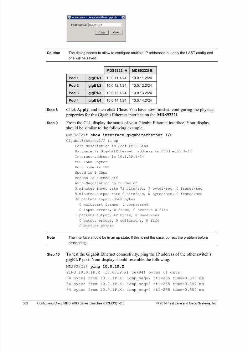
8/18/2019 FL_DCMDS_2.0.3_LG(1).pdf
http://slidepdf.com/reader/full/fldcmds203lg1pdf 362/482
362 Configuring Cisco MDS 9000 Series Switches (DCMDS) v2.0 © 2014 Fast Lane and Cisco Systems, Inc.
Caution The dialog seems to allow to configure multiple IP addresses but only the LAST configured
one will be saved.
MDS9222i-A MDS9222i-B
Pod 1 gigE1/1 10.0.11.1/24 10.0.11.2/24
Pod 2 gigE1/2 10.0.12.1/24 10.0.12.2/24
Pod 3 gigE1/3 10.0.13.1/24 10.0.13.2/24
Pod 4 gigE1/4 10.0.14.1/24 10.0.14.2/24
Step 8 Click Apply, and then click Close. You have now finished configuring the physical
properties for the Gigabit Ethernet interface on the MDS9222i.
Step 9 From the CLI, display the status of your Gigabit Ethernet interface. Your displayshould be similar to the following example.
MDS9222i# show interface gigabitethernet 1/P
GigabitEthernet1/P is up
Port description is Pod# FCIP Link
Hardware is GigabitEthernet, address is 000d.ec75.3af8
Internet address is 10.1.1P.1/24
MTU 1500 bytes
Port mode is IPS
Speed is 1 Gbps
Beacon is turned off
Auto-Negotiation is turned on5 minutes input rate 72 bits/sec, 9 bytes/sec, 0 frames/sec
5 minutes output rate 0 bits/sec, 0 bytes/sec, 0 frames/sec
30 packets input, 8568 bytes
0 multicast frames, 0 compressed
0 input errors, 0 frame, 0 overrun 0 fifo
1 packets output, 42 bytes, 0 underruns
0 output errors, 0 collisions, 0 fifo
0 carrier errors
Note The interface should be in an up state. If this is not the case, correct the problem before
proceeding.
Step 10 To test the Gigabit Ethernet connectivity, ping the IP address of the other switch’s
gigE1/P port. Your display should resemble the following.
MDS9222i# ping 10.0.1P.X
PING 10.0.1P.X (10.0.1P.X) 56(84) bytes of data.
64 bytes from 10.0.1P.X: icmp_seq=2 ttl=255 time=0.379 ms
64 bytes from 10.0.1P.X: icmp_seq=3 ttl=255 time=0.357 ms
64 bytes from 10.0.1P.X: icmp_seq=4 ttl=255 time=0.504 ms

8/18/2019 FL_DCMDS_2.0.3_LG(1).pdf
http://slidepdf.com/reader/full/fldcmds203lg1pdf 363/482
Configuring Cisco MDS 9000 Series Switches (DCMDS) v2.0 Fast Lane Lab Guide 2.0.3 363
64 bytes from 10.0.1P.X: icmp_seq=5 ttl=255 time=0.349 ms
--- 10.0.1P.X ping statistics ---
5 packets transmitted, 4 received, 20% packet loss, time4011ms
rtt min/avg/max/mdev = 0.349/0.397/0.504/0.064 ms
Step 11 If the ping was successful, save your configuration.
POD#-MDS9148-A# copy run start
Activity Verification
You have completed this task when you attain this result:
! You can successfully ping the remote end of your Gigabit Ethernet interface
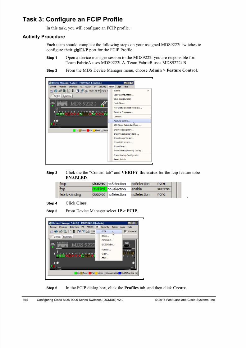
8/18/2019 FL_DCMDS_2.0.3_LG(1).pdf
http://slidepdf.com/reader/full/fldcmds203lg1pdf 364/482
364 Configuring Cisco MDS 9000 Series Switches (DCMDS) v2.0 © 2014 Fast Lane and Cisco Systems, Inc.
Task 3: Configure an FCIP Profile
In this task, you will configure an FCIP profile.
Activity Procedure
Each team should complete the following steps on your assigned MDS9222i switches to
configure their gigE1/P port for the FCIP Profile.
Step 1 Open a device manager session to the MDS9222i you are responsible for:
Team FabricA uses MDS9222i-A, Team FabricB uses MDS9222i-B
Step 2 From the MDS Device Manager menu, choose Admin > Feature Control.
Step 3 Click the the “Control tab” and VERIFY the status for the fcip feature tobe
ENABLED.
Step 4 Click Close.
Step 5 From Device Manager select IP > FCIP.
Step 6 In the FCIP dialog box, click the Profiles tab, and then click Create.
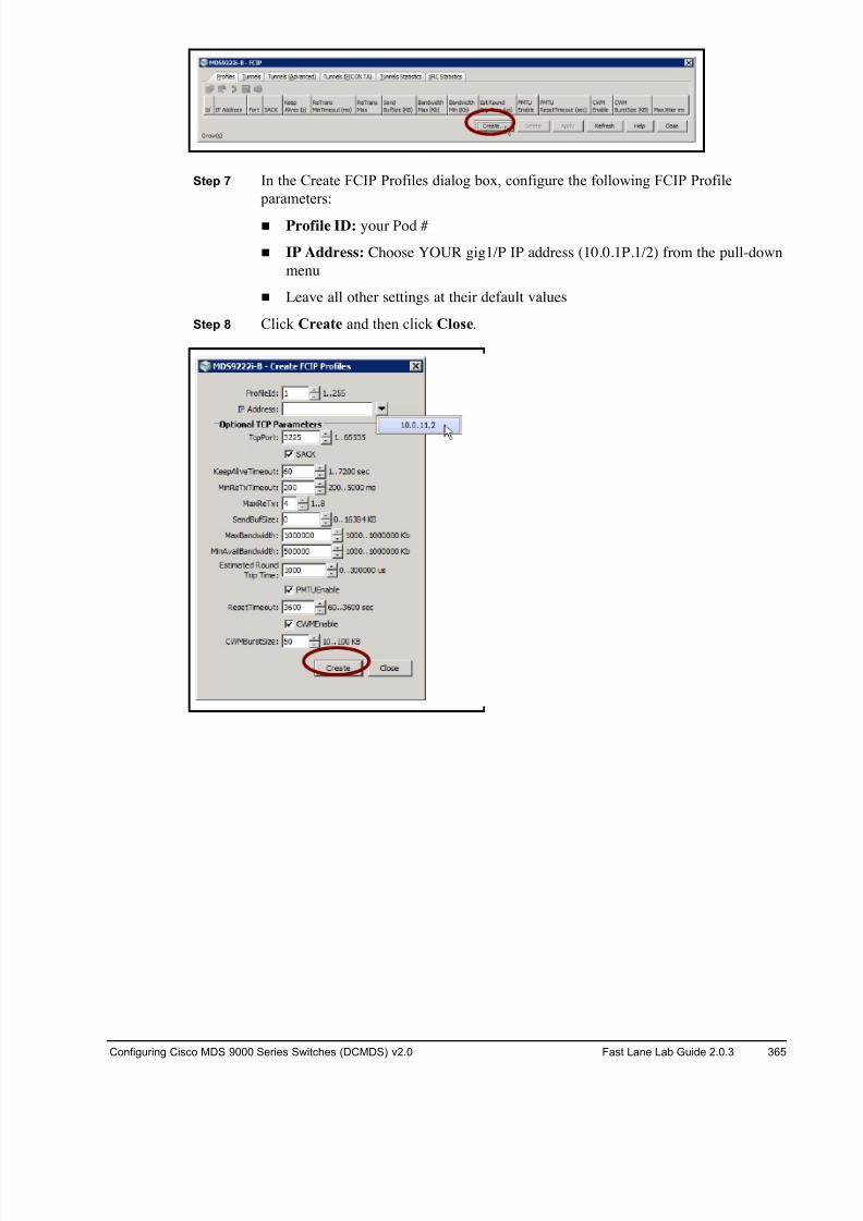
8/18/2019 FL_DCMDS_2.0.3_LG(1).pdf
http://slidepdf.com/reader/full/fldcmds203lg1pdf 365/482
Configuring Cisco MDS 9000 Series Switches (DCMDS) v2.0 Fast Lane Lab Guide 2.0.3 365
Step 7 In the Create FCIP Profiles dialog box, configure the following FCIP Profile
parameters:
! Profile ID: your Pod #
! IP Address: Choose YOUR gig1/P IP address (10.0.1P.1/2) from the pull-down
menu
! Leave all other settings at their default values
Step 8 Click Create and then click Close.
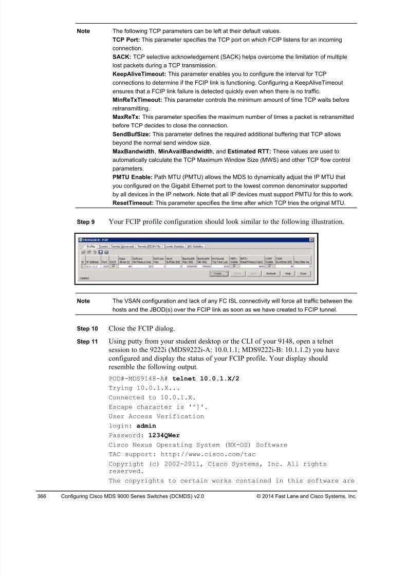
8/18/2019 FL_DCMDS_2.0.3_LG(1).pdf
http://slidepdf.com/reader/full/fldcmds203lg1pdf 366/482
366 Configuring Cisco MDS 9000 Series Switches (DCMDS) v2.0 © 2014 Fast Lane and Cisco Systems, Inc.
Note The following TCP parameters can be left at their default values.
TCP Port: This parameter specifies the TCP port on which FCIP listens for an incoming
connection.
SACK: TCP selective acknowledgement (SACK) helps overcome the limitation of multiple
lost packets during a TCP transmission.
KeepAliveTimeout: This parameter enables you to configure the interval for TCP
connections to determine if the FCIP link is functioning. Configuring a KeepAliveTimeout
ensures that a FCIP link failure is detected quickly even when there is no traffic.
MinReTxTimeout: This parameter controls the minimum amount of time TCP waits beforeretransmitting.
MaxReTx: This parameter specifies the maximum number of times a packet is retransmitted
before TCP decides to close the connection.
SendBufSize: This parameter defines the required additional buffering that TCP allows
beyond the normal send window size.
MaxBandwidth, MinAvailBandwidth, and Estimated RTT: These values are used to
automatically calculate the TCP Maximum Window Size (MWS) and other TCP flow control
parameters.
PMTU Enable: Path MTU (PMTU) allows the MDS to dynamically adjust the IP MTU that
you configured on the Gigabit Ethernet port to the lowest common denominator supported
by all devices in the IP network. Note that all IP devices must support PMTU for this to work.
ResetTimeout: This parameter specifies the time after which TCP tries the original MTU.
Step 9 Your FCIP profile configuration should look similar to the following illustration.
Note The VSAN configuration and lack of any FC ISL connectivity will force all traffic between thehosts and the JBOD(s) over the FCIP link as soon as we have created to FCIP tunnel.
Step 10 Close the FCIP dialog.
Step 11 Using putty from your student desktop or the CLI of your 9148, open a telnet
session to the 9222i (MDS9222i-A: 10.0.1.1; MDS9222i-B: 10.1.1.2) you have
configured and display the status of your FCIP profile. Your display should
resemble the following output.
POD#-MDS9148-A# telnet 10.0.1.X/2
Trying 10.0.1.X...
Connected to 10.0.1.X.
Escape character is '^]'.
User Access Verification
login: admin
Password: 1234QWer
Cisco Nexus Operating System (NX-OS) Software
TAC support: http://www.cisco.com/tac
Copyright (c) 2002-2011, Cisco Systems, Inc. All rightsreserved.
The copyrights to certain works contained in this software are
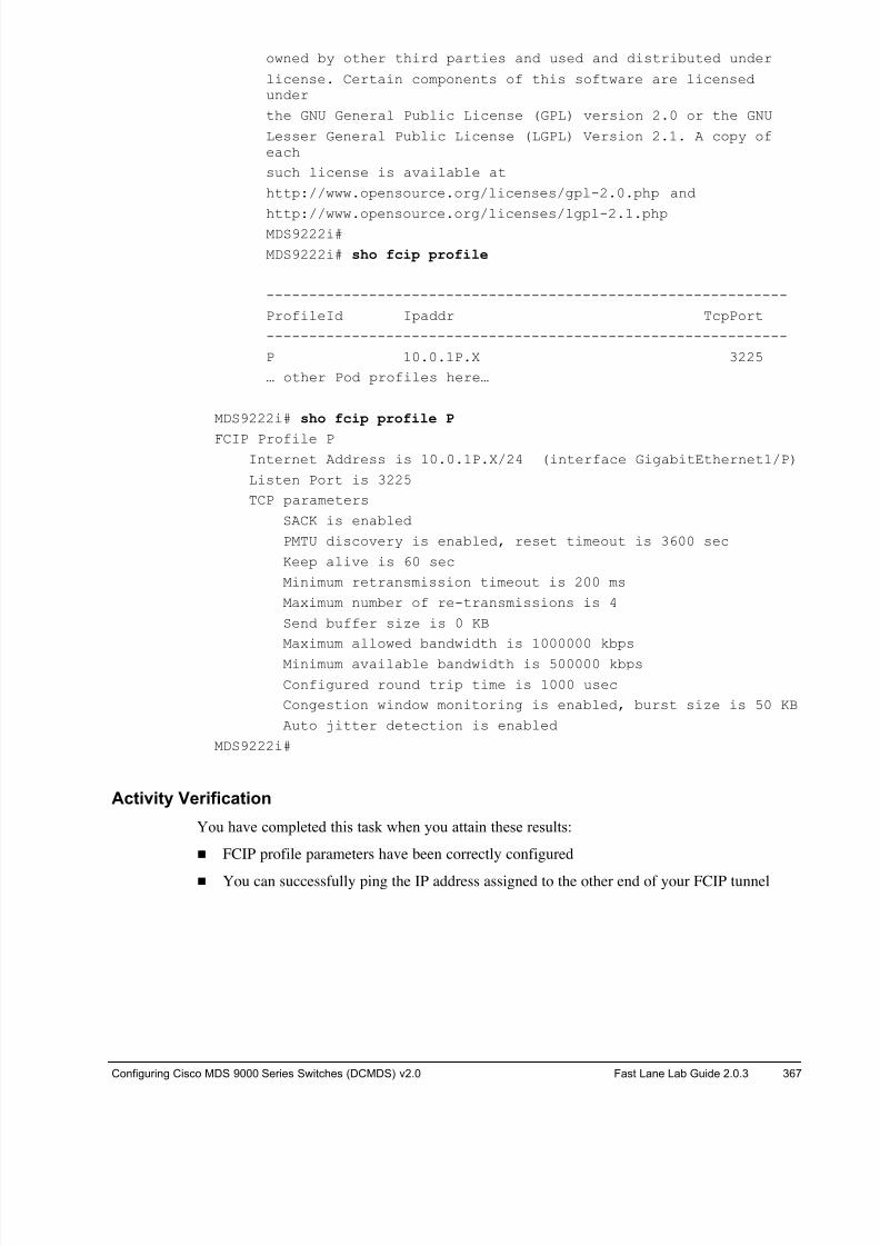
8/18/2019 FL_DCMDS_2.0.3_LG(1).pdf
http://slidepdf.com/reader/full/fldcmds203lg1pdf 367/482
Configuring Cisco MDS 9000 Series Switches (DCMDS) v2.0 Fast Lane Lab Guide 2.0.3 367
owned by other third parties and used and distributed under
license. Certain components of this software are licensedunder
the GNU General Public License (GPL) version 2.0 or the GNU
Lesser General Public License (LGPL) Version 2.1. A copy ofeach
such license is available at
http://www.opensource.org/licenses/gpl-2.0.php and
http://www.opensource.org/licenses/lgpl-2.1.phpMDS9222i#
MDS9222i# sho fcip profile
-------------------------------------------------------------
ProfileId Ipaddr TcpPort
-------------------------------------------------------------
P 10.0.1P.X 3225
… other Pod profiles here…
MDS9222i# sho fcip profile P
FCIP Profile P
Internet Address is 10.0.1P.X/24 (interface GigabitEthernet1/P)
Listen Port is 3225
TCP parameters
SACK is enabled
PMTU discovery is enabled, reset timeout is 3600 sec
Keep alive is 60 sec
Minimum retransmission timeout is 200 ms
Maximum number of re-transmissions is 4
Send buffer size is 0 KB
Maximum allowed bandwidth is 1000000 kbps
Minimum available bandwidth is 500000 kbps
Configured round trip time is 1000 usec
Congestion window monitoring is enabled, burst size is 50 KB
Auto jitter detection is enabled
MDS9222i#
Activity Verification
You have completed this task when you attain these results:
! FCIP profile parameters have been correctly configured
! You can successfully ping the IP address assigned to the other end of your FCIP tunnel
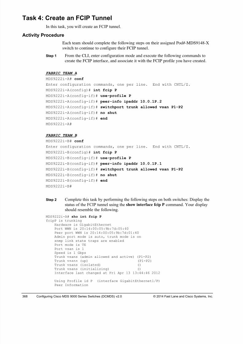
8/18/2019 FL_DCMDS_2.0.3_LG(1).pdf
http://slidepdf.com/reader/full/fldcmds203lg1pdf 368/482
368 Configuring Cisco MDS 9000 Series Switches (DCMDS) v2.0 © 2014 Fast Lane and Cisco Systems, Inc.
Task 4: Create an FCIP Tunnel
In this task, you will create an FCIP tunnel.
Activity Procedure
Each team should complete the following steps on their assigned Pod#-MDS9148-X
switch to continue to configure their FCIP tunnel.
Step 1 From the CLI, enter configuration mode and execute the following commands to
create the FCIP interface, and associate it with the FCIP profile you have created.
FABRIC TEAM A
MDS9222i-A# conf
Enter configuration commands, one per line. End with CNTL/Z.
MDS9222i-A(config)# int fcip P
MDS9222i-A(config-if)# use-profile P
MDS9222i-A(config-if)# peer-info ipaddr 10.0.1P.2
MDS9222i-A(config-if)# switchport trunk allowed vsan P1-P2
MDS9222i-A(config-if)# no shut
MDS9222i-A(config-if)#end
MDS9222i-A#
FABRIC TEAM B
MDS9222i-B# conf
Enter configuration commands, one per line. End with CNTL/Z.
MDS9222i-B(config)# int fcip P
MDS9222i-B(config-if)# use-profile P
MDS9222i-B(config-if)# peer-info ipaddr 10.0.1P.1
MDS9222i-B(config-if)# switchport trunk allowed vsan P1-P2
MDS9222i-B(config-if)# no shut
MDS9222i-B(config-if)# end MDS9222i-B#
Step 2 Complete this task by performing the following steps on both switches: Display the
status of the FCIP tunnel using the show interface fcip P command. Your display
should resemble the following.
MDS9222i-A# sho int fcip P fcipP is trunking
Hardware is GigabitEthernetPort WWN is 20:14:00:05:9b:7d:05:40Peer port WWN is 20:14:00:05:9b:7d:01:40Admin port mode is auto, trunk mode is on
snmp link state traps are enabledPort mode is TEPort vsan is 1Speed is 1 GbpsTrunk vsans (admin allowed and active) (P1-P2)Trunk vsans (up) (P1-P2)Trunk vsans (isolated) ()Trunk vsans (initializing) ()Interface last changed at Fri Apr 13 13:44:46 2012
Using Profile id P (interface GigabitEthernet1/P)Peer Information
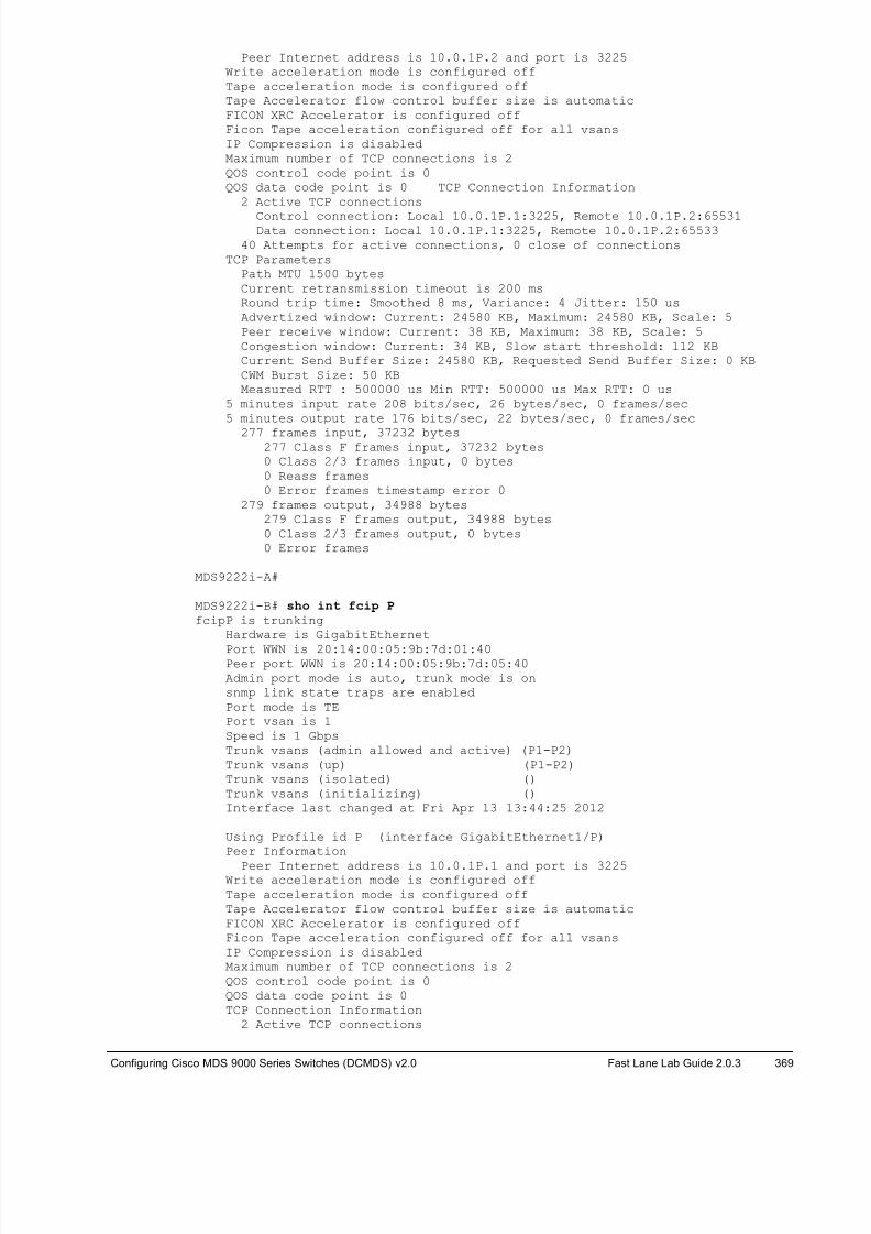
8/18/2019 FL_DCMDS_2.0.3_LG(1).pdf
http://slidepdf.com/reader/full/fldcmds203lg1pdf 369/482
Configuring Cisco MDS 9000 Series Switches (DCMDS) v2.0 Fast Lane Lab Guide 2.0.3 369
Peer Internet address is 10.0.1P.2 and port is 3225Write acceleration mode is configured offTape acceleration mode is configured offTape Accelerator flow control buffer size is automaticFICON XRC Accelerator is configured offFicon Tape acceleration configured off for all vsansIP Compression is disabledMaximum number of TCP connections is 2QOS control code point is 0QOS data code point is 0 TCP Connection Information
2 Active TCP connections
Control connection: Local 10.0.1P.1:3225, Remote 10.0.1P.2:65531Data connection: Local 10.0.1P.1:3225, Remote 10.0.1P.2:65533
40 Attempts for active connections, 0 close of connectionsTCP Parameters
Path MTU 1500 bytesCurrent retransmission timeout is 200 msRound trip time: Smoothed 8 ms, Variance: 4 Jitter: 150 usAdvertized window: Current: 24580 KB, Maximum: 24580 KB, Scale: 5Peer receive window: Current: 38 KB, Maximum: 38 KB, Scale: 5Congestion window: Current: 34 KB, Slow start threshold: 112 KBCurrent Send Buffer Size: 24580 KB, Requested Send Buffer Size: 0 KBCWM Burst Size: 50 KBMeasured RTT : 500000 us Min RTT: 500000 us Max RTT: 0 us
5 minutes input rate 208 bits/sec, 26 bytes/sec, 0 frames/sec5 minutes output rate 176 bits/sec, 22 bytes/sec, 0 frames/sec
277 frames input, 37232 bytes277 Class F frames input, 37232 bytes0 Class 2/3 frames input, 0 bytes0 Reass frames0 Error frames timestamp error 0
279 frames output, 34988 bytes279 Class F frames output, 34988 bytes0 Class 2/3 frames output, 0 bytes0 Error frames
MDS9222i-A#
MDS9222i-B# sho int fcip P fcipP is trunking
Hardware is GigabitEthernet
Port WWN is 20:14:00:05:9b:7d:01:40Peer port WWN is 20:14:00:05:9b:7d:05:40Admin port mode is auto, trunk mode is onsnmp link state traps are enabledPort mode is TEPort vsan is 1Speed is 1 GbpsTrunk vsans (admin allowed and active) (P1-P2)Trunk vsans (up) (P1-P2)Trunk vsans (isolated) ()Trunk vsans (initializing) ()Interface last changed at Fri Apr 13 13:44:25 2012
Using Profile id P (interface GigabitEthernet1/P)Peer Information
Peer Internet address is 10.0.1P.1 and port is 3225Write acceleration mode is configured offTape acceleration mode is configured offTape Accelerator flow control buffer size is automaticFICON XRC Accelerator is configured offFicon Tape acceleration configured off for all vsansIP Compression is disabledMaximum number of TCP connections is 2QOS control code point is 0QOS data code point is 0TCP Connection Information
2 Active TCP connections
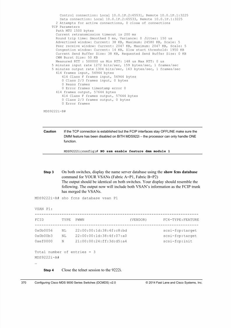
8/18/2019 FL_DCMDS_2.0.3_LG(1).pdf
http://slidepdf.com/reader/full/fldcmds203lg1pdf 370/482
370 Configuring Cisco MDS 9000 Series Switches (DCMDS) v2.0 © 2014 Fast Lane and Cisco Systems, Inc.
Control connection: Local 10.0.1P.2:65531, Remote 10.0.1P.1:3225Data connection: Local 10.0.1P.2:65533, Remote 10.0.1P.1:3225
2 Attempts for active connections, 0 close of connectionsTCP Parameters
Path MTU 1500 bytesCurrent retransmission timeout is 200 msRound trip time: Smoothed 0 ms, Variance: 0 Jitter: 150 usAdvertized window: Current: 38 KB, Maximum: 24580 KB, Scale: 5Peer receive window: Current: 2047 KB, Maximum: 2047 KB, Scale: 5Congestion window: Current: 14 KB, Slow start threshold: 1950 KBCurrent Send Buffer Size: 38 KB, Requested Send Buffer Size: 0 KB
CWM Burst Size: 50 KBMeasured RTT : 500000 us Min RTT: 148 us Max RTT: 0 us
5 minutes input rate 1272 bits/sec, 159 bytes/sec, 1 frames/sec5 minutes output rate 1304 bits/sec, 163 bytes/sec, 1 frames/sec
414 frames input, 54944 bytes414 Class F frames input, 54944 bytes0 Class 2/3 frames input, 0 bytes0 Reass frames0 Error frames timestamp error 0
414 frames output, 57644 bytes414 Class F frames output, 57644 bytes0 Class 2/3 frames output, 0 bytes0 Error frames
MDS9222i-B#
Caution If the TCP connection is established but the FCIP interfaces stay OFFLINE make sure the
DMM feature has been disabled on BITH MDS922i – the processor can only handle ONE
function.
MDS9222i(config)# NO ssm enable feature dmm module 1
Step 3 On both switches, display the name server database using the show fcns database command for YOUR VSANs (Fabric A=P1, Fabric B=P2)
The output should be identical on both switches. Your display should resemble the
following. The output now will include both VSAN’s information as the FCIP trunk
has merged the VSANs.
MDS9222i-A# sho fcns database vsan P1
VSAN P1:
-------------------------------------------------------------------------
FCID TYPE PWWN (VENDOR) FC4-TYPE:FEATURE
-------------------------------------------------------------------------
0x0b0056 NL 22:00:00:1d:38:4f:c8:bd scsi-fcp:target0x0b00b3 NL 22:00:00:1d:38:4f:07:a0 scsi-fcp:target
0xef0000 N 21:00:00:24:ff:3d:d5:a4 scsi-fcp:init
Total number of entries = 3
MDS9222i-A#
…
Step 4 Close the telnet session to the 9222i.
8/18/2019 FL_DCMDS_2.0.3_LG(1).pdf
http://slidepdf.com/reader/full/fldcmds203lg1pdf 371/482
Configuring Cisco MDS 9000 Series Switches (DCMDS) v2.0 Fast Lane Lab Guide 2.0.3 371
Activity Verification
You have completed this task when you attain these results:
! FCIP tunnel parameters have been correctly configured, as verified in this task
! Your switch Port WWN displayed is the Peer port WWN displayed on the other switch, as
verified in this task
! The name server database displayed for both switches is identical, as verified in this task
You have saved your configuration
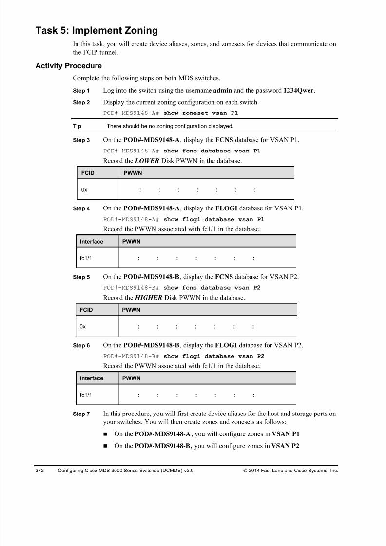
8/18/2019 FL_DCMDS_2.0.3_LG(1).pdf
http://slidepdf.com/reader/full/fldcmds203lg1pdf 372/482
372 Configuring Cisco MDS 9000 Series Switches (DCMDS) v2.0 © 2014 Fast Lane and Cisco Systems, Inc.
Task 5: Implement Zoning
In this task, you will create device aliases, zones, and zonesets for devices that communicate on
the FCIP tunnel.
Activity Procedure
Complete the following steps on both MDS switches.
Step 1 Log into the switch using the username admin and the password 1234Qwer.
Step 2 Display the current zoning configuration on each switch.
POD#-MDS9148-A# show zoneset vsan P1
Tip There should be no zoning configuration displayed.
Step 3 On the POD#-MDS9148-A, display the FCNS database for VSAN P1.
POD#-MDS9148-A# show fcns database vsan P1
Record the LOWER Disk PWWN in the database.
FCID PWWN
0x : : : : : : :
Step 4 On the POD#-MDS9148-A, display the FLOGI database for VSAN P1.
POD#-MDS9148-A# show flogi database vsan P1
Record the PWWN associated with fc1/1 in the database.
Interface PWWN
fc1/1 : : : : : : :
Step 5 On the POD#-MDS9148-B, display the FCNS database for VSAN P2.
POD#-MDS9148-B# show fcns database vsan P2
Record the HIGHER Disk PWWN in the database.
FCID PWWN
0x : : : : : : :
Step 6 On the POD#-MDS9148-B, display the FLOGI database for VSAN P2.
POD#-MDS9148-B# show flogi database vsan P2
Record the PWWN associated with fc1/1 in the database.
Interface PWWN
fc1/1 : : : : : : :
Step 7 In this procedure, you will first create device aliases for the host and storage ports on
your switches. You will then create zones and zonesets as follows:
! On the POD#-MDS9148-A, you will configure zones in VSAN P1
! On the POD#-MDS9148-B, you will configure zones in VSAN P2
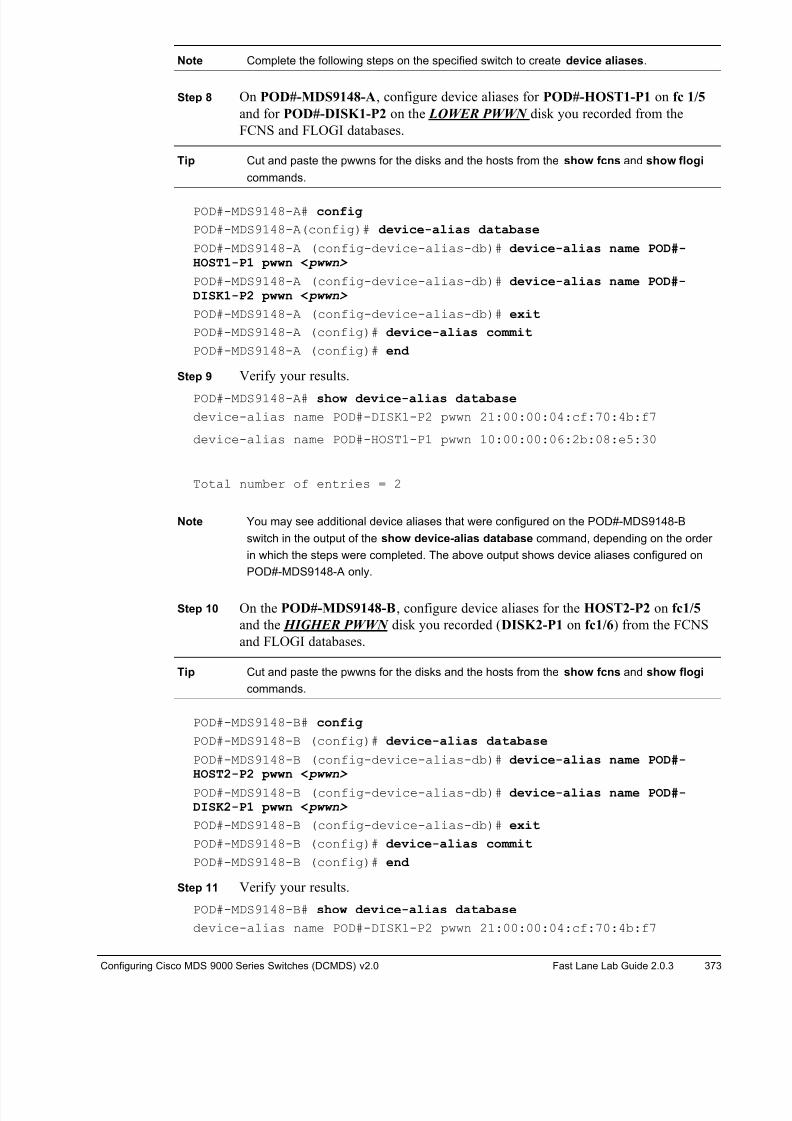
8/18/2019 FL_DCMDS_2.0.3_LG(1).pdf
http://slidepdf.com/reader/full/fldcmds203lg1pdf 373/482
Configuring Cisco MDS 9000 Series Switches (DCMDS) v2.0 Fast Lane Lab Guide 2.0.3 373
Note Complete the following steps on the specified switch to create device aliases.
Step 8 On POD#-MDS9148-A, configure device aliases for POD#-HOST1-P1 on fc 1/5
and for POD#-DISK1-P2 on the LOWER PWWN disk you recorded from the
FCNS and FLOGI databases.
Tip Cut and paste the pwwns for the disks and the hosts from the show fcns and show flogi
commands.
POD#-MDS9148-A# config
POD#-MDS9148-A(config)# device-alias database
POD#-MDS9148-A (config-device-alias-db)# device-alias name POD#-HOST1-P1 pwwn < pwwn>
POD#-MDS9148-A (config-device-alias-db)# device-alias name POD#-DISK1-P2 pwwn < pwwn>
POD#-MDS9148-A (config-device-alias-db)# exit
POD#-MDS9148-A (config)# device-alias commit
POD#-MDS9148-A (config)# end
Step 9 Verify your results.
POD#-MDS9148-A# show device-alias database
device-alias name POD#-DISK1-P2 pwwn 21:00:00:04:cf:70:4b:f7
device-alias name POD#-HOST1-P1 pwwn 10:00:00:06:2b:08:e5:30
Total number of entries = 2
Note You may see additional device aliases that were configured on the POD#-MDS9148-B
switch in the output of the show device-alias database command, depending on the order
in which the steps were completed. The above output shows device aliases configured on
POD#-MDS9148-A only.
Step 10 On the POD#-MDS9148-B, configure device aliases for the HOST2-P2 on fc1/5
and the HIGHER PWWN disk you recorded (DISK2-P1 on fc1/6) from the FCNS
and FLOGI databases.
Tip Cut and paste the pwwns for the disks and the hosts from the show fcns and show flogi
commands.
POD#-MDS9148-B# config
POD#-MDS9148-B (config)# device-alias database
POD#-MDS9148-B (config-device-alias-db)# device-alias name POD#-HOST2-P2 pwwn < pwwn>
POD#-MDS9148-B (config-device-alias-db)# device-alias name POD#-DISK2-P1 pwwn < pwwn>
POD#-MDS9148-B (config-device-alias-db)# exit
POD#-MDS9148-B (config)# device-alias commit
POD#-MDS9148-B (config)# end
Step 11 Verify your results.
POD#-MDS9148-B# show device-alias database
device-alias name POD#-DISK1-P2 pwwn 21:00:00:04:cf:70:4b:f7
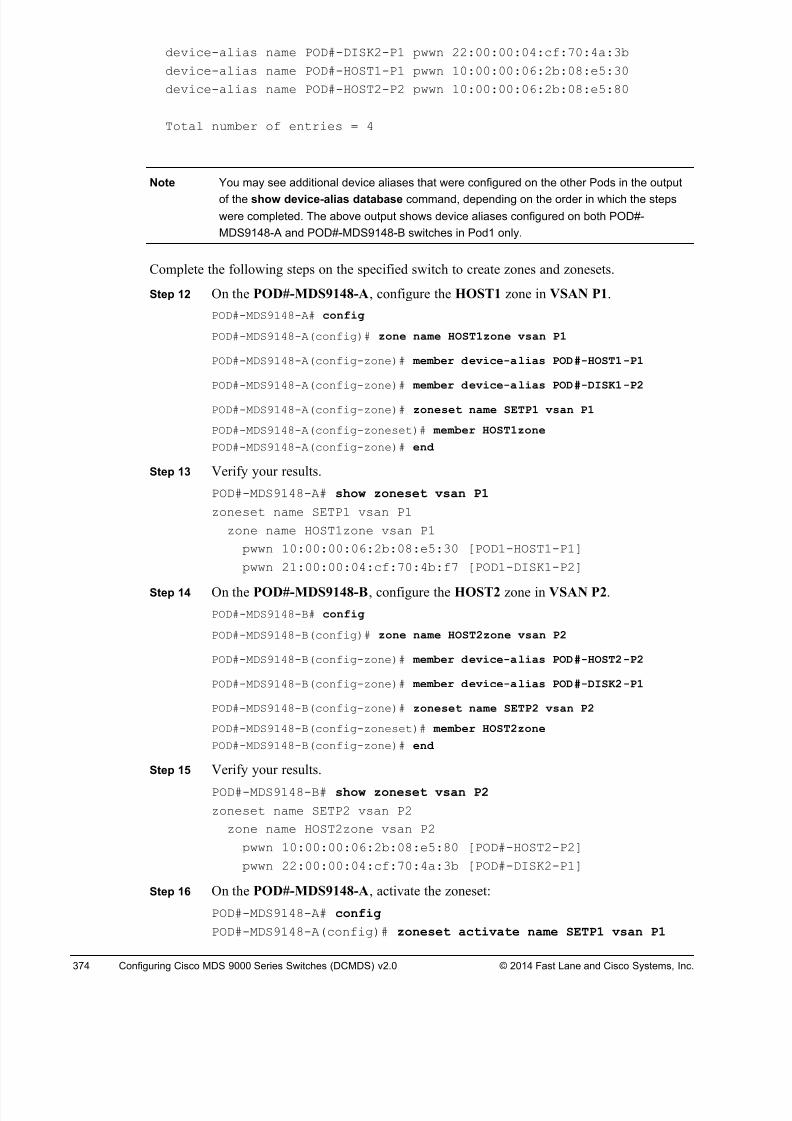
8/18/2019 FL_DCMDS_2.0.3_LG(1).pdf
http://slidepdf.com/reader/full/fldcmds203lg1pdf 374/482
374 Configuring Cisco MDS 9000 Series Switches (DCMDS) v2.0 © 2014 Fast Lane and Cisco Systems, Inc.
device-alias name POD#-DISK2-P1 pwwn 22:00:00:04:cf:70:4a:3b
device-alias name POD#-HOST1-P1 pwwn 10:00:00:06:2b:08:e5:30
device-alias name POD#-HOST2-P2 pwwn 10:00:00:06:2b:08:e5:80
Total number of entries = 4
Note You may see additional device aliases that were configured on the other Pods in the output
of the show device-alias database command, depending on the order in which the steps
were completed. The above output shows device aliases configured on both POD#-
MDS9148-A and POD#-MDS9148-B switches in Pod1 only.
Complete the following steps on the specified switch to create zones and zonesets.
Step 12 On the POD#-MDS9148-A, configure the HOST1 zone in VSAN P1.
POD#-MDS9148-A# config
POD#-MDS9148-A(config)# zone name HOST1zone vsan P1
POD#-MDS9148-A(config-zone)# member device-alias POD#-HOST1-P1
POD#-MDS9148-A(config-zone)# member device-alias POD#-DISK1-P2
POD#-MDS9148-A(config-zone)# zoneset name SETP1 vsan P1
POD#-MDS9148-A(config-zoneset)# member HOST1zone
POD#-MDS9148-A(config-zone)# end
Step 13 Verify your results.
POD#-MDS9148-A# show zoneset vsan P1
zoneset name SETP1 vsan P1
zone name HOST1zone vsan P1
pwwn 10:00:00:06:2b:08:e5:30 [POD1-HOST1-P1]
pwwn 21:00:00:04:cf:70:4b:f7 [POD1-DISK1-P2]
Step 14 On the POD#-MDS9148-B, configure the HOST2 zone in VSAN P2.
POD#-MDS9148-B# config
POD#-MDS9148-B(config)# zone name HOST2zone vsan P2
POD#-MDS9148-B(config-zone)# member device-alias POD#-HOST2-P2
POD#-MDS9148-B(config-zone)# member device-alias POD#-DISK2-P1
POD#-MDS9148-B(config-zone)# zoneset name SETP2 vsan P2
POD#-MDS9148-B(config-zoneset)# member HOST2zone
POD#-MDS9148-B(config-zone)# end
Step 15 Verify your results.
POD#-MDS9148-B# show zoneset vsan P2
zoneset name SETP2 vsan P2
zone name HOST2zone vsan P2
pwwn 10:00:00:06:2b:08:e5:80 [POD#-HOST2-P2]
pwwn 22:00:00:04:cf:70:4a:3b [POD#-DISK2-P1]
Step 16 On the POD#-MDS9148-A, activate the zoneset:
POD#-MDS9148-A# config
POD#-MDS9148-A(config)# zoneset activate name SETP1 vsan P1
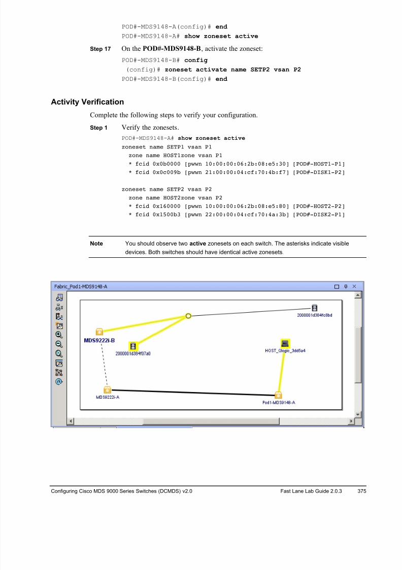
8/18/2019 FL_DCMDS_2.0.3_LG(1).pdf
http://slidepdf.com/reader/full/fldcmds203lg1pdf 375/482
Configuring Cisco MDS 9000 Series Switches (DCMDS) v2.0 Fast Lane Lab Guide 2.0.3 375
POD#-MDS9148-A(config)# end
POD#-MDS9148-A# show zoneset active
Step 17 On the POD#-MDS9148-B, activate the zoneset:
POD#-MDS9148-B# config
(config)# zoneset activate name SETP2 vsan P2
POD#-MDS9148-B(config)# end
Activity Verification
Complete the following steps to verify your configuration.
Step 1 Verify the zonesets.
POD#-MDS9148-A# show zoneset active
zoneset name SETP1 vsan P1
zone name HOST1zone vsan P1
* fcid 0x0b0000 [pwwn 10:00:00:06:2b:08:e5:30] [POD#-HOST1-P1]
* fcid 0x0c009b [pwwn 21:00:00:04:cf:70:4b:f7] [POD#-DISK1-P2]
zoneset name SETP2 vsan P2
zone name HOST2zone vsan P2* fcid 0x160000 [pwwn 10:00:00:06:2b:08:e5:80] [POD#-HOST2-P2]
* fcid 0x1500b3 [pwwn 22:00:00:04:cf:70:4a:3b] [POD#-DISK2-P1]
Note You should observe two active zonesets on each switch. The asterisks indicate visible
devices. Both switches should have identical active zonesets.
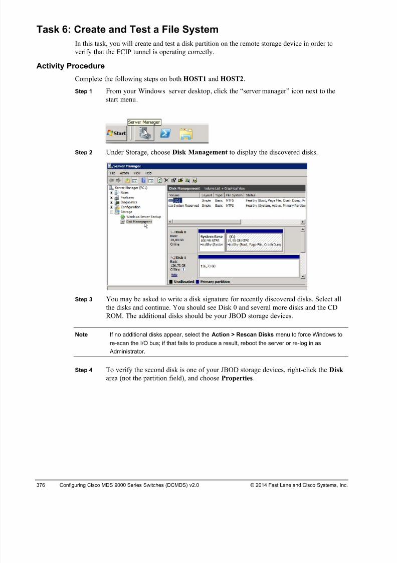
8/18/2019 FL_DCMDS_2.0.3_LG(1).pdf
http://slidepdf.com/reader/full/fldcmds203lg1pdf 376/482
376 Configuring Cisco MDS 9000 Series Switches (DCMDS) v2.0 © 2014 Fast Lane and Cisco Systems, Inc.
Task 6: Create and Test a File System
In this task, you will create and test a disk partition on the remote storage device in order to
verify that the FCIP tunnel is operating correctly.
Activity Procedure
Complete the following steps on both HOST1 and HOST2.
Step 1 From your Windows server desktop, click the “server manager” icon next to the
start menu.
Step 2 Under Storage, choose Disk Management to display the discovered disks.
Step 3 You may be asked to write a disk signature for recently discovered disks. Select all
the disks and continue. You should see Disk 0 and several more disks and the CD
ROM. The additional disks should be your JBOD storage devices.
Note If no additional disks appear, select the Action > Rescan Disks menu to force Windows to
re-scan the I/O bus; if that fails to produce a result, reboot the server or re-log in as
Administrator.
Step 4 To verify the second disk is one of your JBOD storage devices, right-click the Disk
area (not the partition field), and choose Properties.
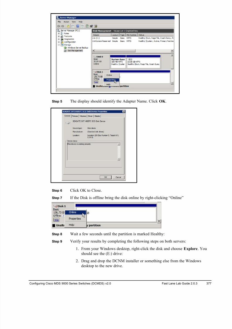
8/18/2019 FL_DCMDS_2.0.3_LG(1).pdf
http://slidepdf.com/reader/full/fldcmds203lg1pdf 377/482
Configuring Cisco MDS 9000 Series Switches (DCMDS) v2.0 Fast Lane Lab Guide 2.0.3 377
Step 5 The display should identify the Adapter Name. Click OK .
Step 6 Click OK to Close.
Step 7 If the Disk is offline bring the disk online by right-clicking “Online”
Step 8 Wait a few seconds until the partition is marked Healthy:
Step 9 Verify your results by completing the following steps on both servers:
1. From your Windows desktop, right-click the disk and choose Explore. You
should see the (E:) drive:
2. Drag and drop the DCNM installer or something else from the Windows
desktop to the new drive.
8/18/2019 FL_DCMDS_2.0.3_LG(1).pdf
http://slidepdf.com/reader/full/fldcmds203lg1pdf 378/482
378 Configuring Cisco MDS 9000 Series Switches (DCMDS) v2.0 © 2014 Fast Lane and Cisco Systems, Inc.
Activity Verification
You have successfully completed this task when you attain this result:
! You were able to create a disk partition, format it, and copy files to the new file system on
each server
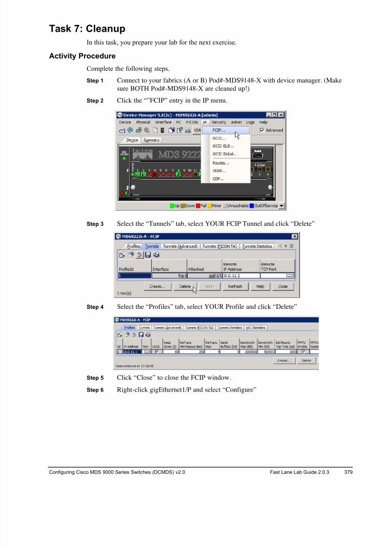
8/18/2019 FL_DCMDS_2.0.3_LG(1).pdf
http://slidepdf.com/reader/full/fldcmds203lg1pdf 379/482
Configuring Cisco MDS 9000 Series Switches (DCMDS) v2.0 Fast Lane Lab Guide 2.0.3 379
Task 7: Cleanup
In this task, you prepare your lab for the next exercise.
Activity Procedure
Complete the following steps.
Step 1 Connect to your fabrics (A or B) Pod#-MDS9148-X with device manager. (Make
sure BOTH Pod#-MDS9148-X are cleaned up!)
Step 2 Click the “”FCIP” entry in the IP menu.
Step 3 Select the “Tunnels” tab, select YOUR FCIP Tunnel and click “Delete”
Step 4 Select the “Profiles” tab, select YOUR Profile and click “Delete”
Step 5 Click “Close” to close the FCIP window.
Step 6 Right-click gigEthernet1/P and select “Configure”
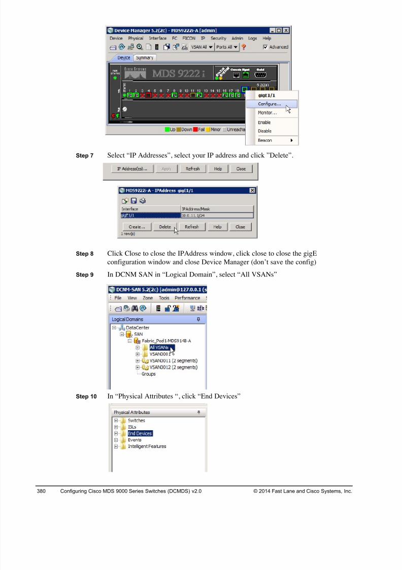
8/18/2019 FL_DCMDS_2.0.3_LG(1).pdf
http://slidepdf.com/reader/full/fldcmds203lg1pdf 380/482
380 Configuring Cisco MDS 9000 Series Switches (DCMDS) v2.0 © 2014 Fast Lane and Cisco Systems, Inc.
Step 7 Select “IP Addresses”, select your IP address and click ”Delete”.
Step 8 Click Close to close the IPAddress window, click close to close the gigE
configuration window and close Device Manager (don’t save the config)
Step 9 In DCNM SAN in “Logical Domain”, select “All VSANs”
Step 10 In “Physical Attributes “, click “End Devices”
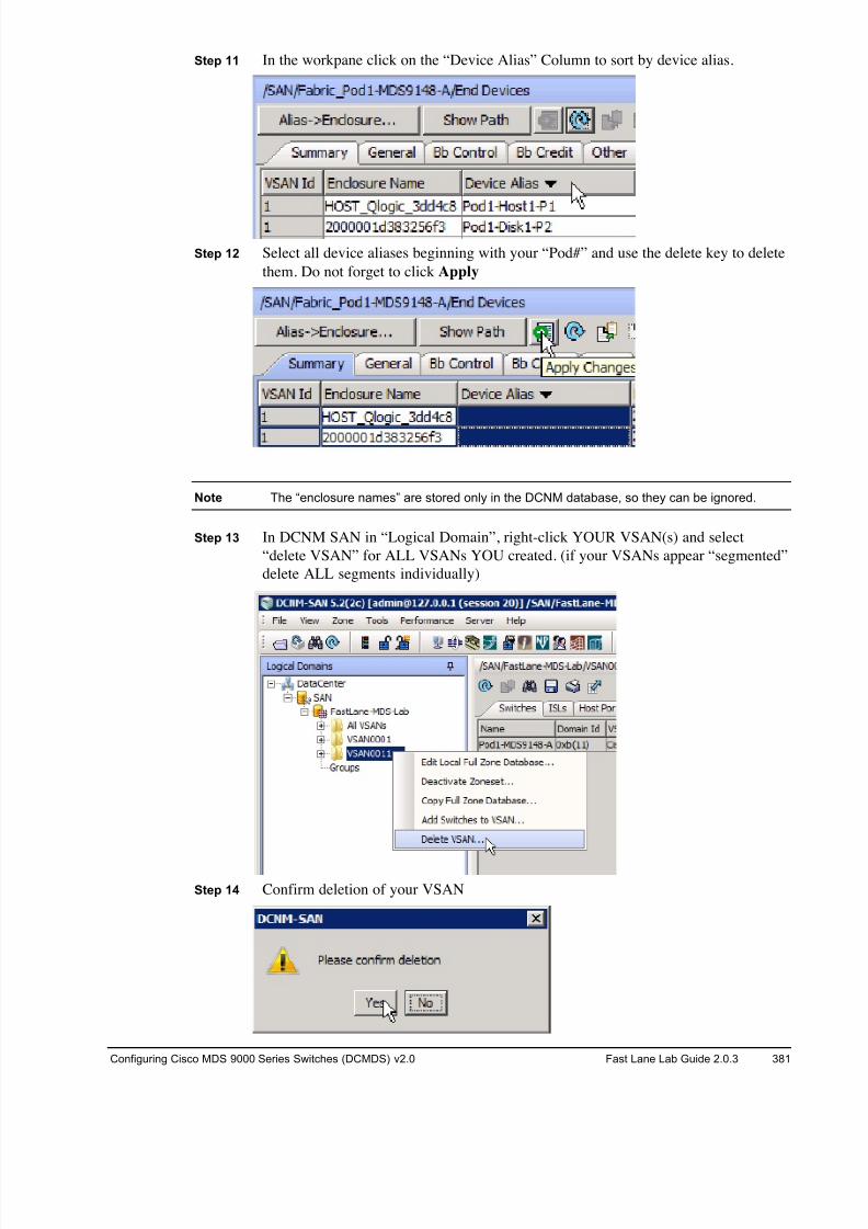
8/18/2019 FL_DCMDS_2.0.3_LG(1).pdf
http://slidepdf.com/reader/full/fldcmds203lg1pdf 381/482
Configuring Cisco MDS 9000 Series Switches (DCMDS) v2.0 Fast Lane Lab Guide 2.0.3 381
Step 11 In the workpane click on the “Device Alias” Column to sort by device alias.
Step 12 Select all device aliases beginning with your “Pod#” and use the delete key to delete
them. Do not forget to click Apply
Note The “enclosure names” are stored only in the DCNM database, so they can be ignored.
Step 13 In DCNM SAN in “Logical Domain”, right-click YOUR VSAN(s) and select
“delete VSAN” for ALL VSANs YOU created. (if your VSANs appear “segmented”
delete ALL segments individually)
Step 14 Confirm deletion of your VSAN
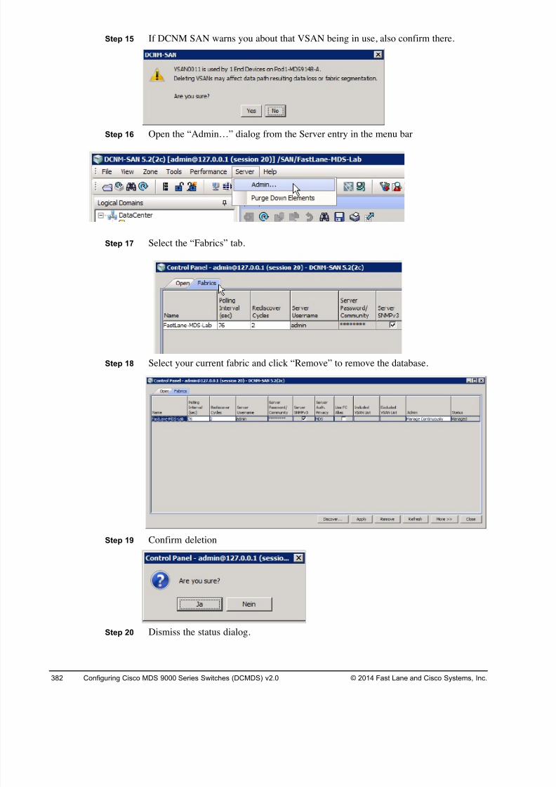
8/18/2019 FL_DCMDS_2.0.3_LG(1).pdf
http://slidepdf.com/reader/full/fldcmds203lg1pdf 382/482
382 Configuring Cisco MDS 9000 Series Switches (DCMDS) v2.0 © 2014 Fast Lane and Cisco Systems, Inc.
Step 15 If DCNM SAN warns you about that VSAN being in use, also confirm there.
Step 16 Open the “Admin…” dialog from the Server entry in the menu bar
Step 17 Select the “Fabrics” tab.
Step 18 Select your current fabric and click “Remove” to remove the database.
Step 19 Confirm deletion
Step 20 Dismiss the status dialog.
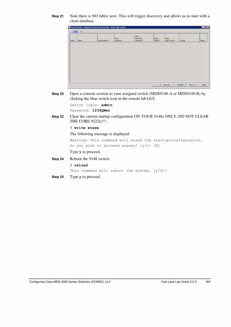
8/18/2019 FL_DCMDS_2.0.3_LG(1).pdf
http://slidepdf.com/reader/full/fldcmds203lg1pdf 383/482
Configuring Cisco MDS 9000 Series Switches (DCMDS) v2.0 Fast Lane Lab Guide 2.0.3 383
Step 21 Note there is NO fabric now. This will trigger discovery and allows us to start with a
clean database.
Step 22 Open a console session to your assigned switch (MDS9148-A or MDS9148-B) by
clicking the blue switch icon in the remote lab GUI.
Switch login: admin
Password: 1234QWer
Step 23 Clear the current startup configuration ON YOUR 9148s ONLY, DO NOT CLEAR
THE CORE 9222is!!! .
# write erase
The following message is displayed:
Warning: This command will erase the startup-configuration.
Do you wish to proceed anyway? [y/n] [N]
Type y to proceed.
Step 24 Reboot the 9148 switch.
# reload
This command will reboot the system. (y/n)? Step 25 Type y to proceed.
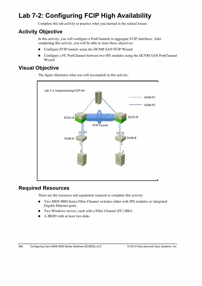
8/18/2019 FL_DCMDS_2.0.3_LG(1).pdf
http://slidepdf.com/reader/full/fldcmds203lg1pdf 384/482
384 Configuring Cisco MDS 9000 Series Switches (DCMDS) v2.0 © 2014 Fast Lane and Cisco Systems, Inc.
Lab 7-2: Configuring FCIP High Availability Complete this lab activity to practice what you learned in the related lesson.
Activity Objective
In this activity, you will configure a PortChannels to aggregate FCIP interfaces. After
completing this activity, you will be able to meet these objectives:
! Configure FCIP tunnels using the DCNM SAN FCIP Wizard
! Configure a FC PortChannel between two IPS modules using the DCNM SAN PortChannel
Wizard
Visual Objective
The figure illustrates what you will accomplish in this activity:
Required Resources
These are the resources and equipment required to complete this activity:
! Two MDS 9000 Series Fibre Channel switches either with IPS modules or integratedGigabit Ethernet ports.
! Two Windows servers, each with a Fibre Channel (FC) HBA.
! A JBOD with at least two disks
! !
!# !! !#!!
! #
$!%&'( $!%&')
$###*'( $###*')
+,- .'#/ 01234145657 890: ;(
<=(> :!
<=(> :#
890: ?@5543
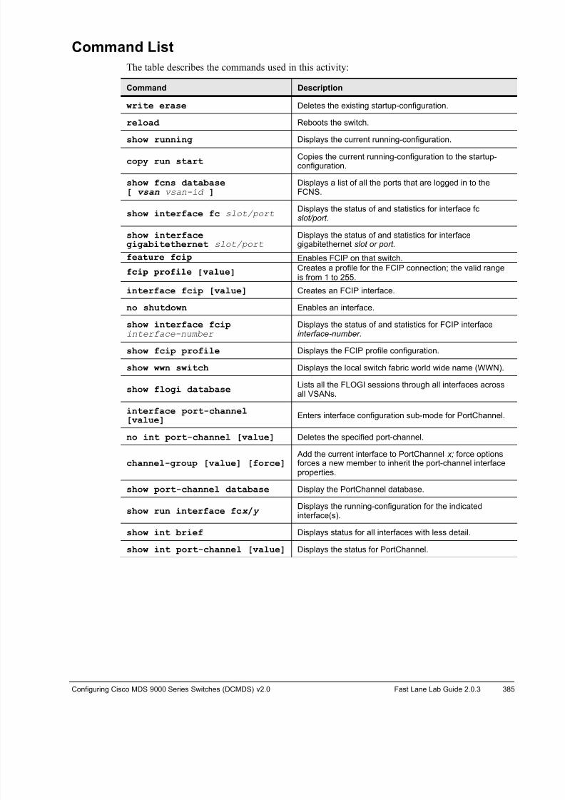
8/18/2019 FL_DCMDS_2.0.3_LG(1).pdf
http://slidepdf.com/reader/full/fldcmds203lg1pdf 385/482
Configuring Cisco MDS 9000 Series Switches (DCMDS) v2.0 Fast Lane Lab Guide 2.0.3 385
Command List
The table describes the commands used in this activity:
Command Description
write erase Deletes the existing startup-configuration.
reload Reboots the switch.
show running Displays the current running-configuration.
copy run startCopies the current running-configuration to the startup-configuration.
show fcns database[ vsan vsan-id ]
Displays a list of all the ports that are logged in to theFCNS.
show interface fc slot/port Displays the status of and statistics for interface fc slot/port.
show interfacegigabitethernet slot/port
Displays the status of and statistics for interfacegigabitethernet slot or port.
feature fcip Enables FCIP on that switch.
fcip profile [value]Creates a profile for the FCIP connection; the valid range
is from 1 to 255.interface fcip [value] Creates an FCIP interface.
no shutdown Enables an interface.
show interface fcipinterface-number
Displays the status of and statistics for FCIP interfaceinterface-number.
show fcip profile Displays the FCIP profile configuration.
show wwn switch Displays the local switch fabric world wide name (WWN).
show flogi databaseLists all the FLOGI sessions through all interfaces acrossall VSANs.
interface port-channel
[value]Enters interface configuration sub-mode for PortChannel.
no int port-channel [value] Deletes the specified port-channel.
channel-group [value] [force] Add the current interface to PortChannel x; force optionsforces a new member to inherit the port-channel interfaceproperties.
show port-channel database Display the PortChannel database.
show run interface fcx / y Displays the running-configuration for the indicatedinterface(s).
show int brief Displays status for all interfaces with less detail.
show int port-channel [value] Displays the status for PortChannel.
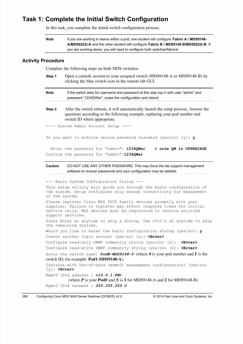
8/18/2019 FL_DCMDS_2.0.3_LG(1).pdf
http://slidepdf.com/reader/full/fldcmds203lg1pdf 386/482
386 Configuring Cisco MDS 9000 Series Switches (DCMDS) v2.0 © 2014 Fast Lane and Cisco Systems, Inc.
Task 1: Complete the Initial Switch Configuration
In this task, you complete the initial switch configuration process.
Note If you are working in teams within a pod, one student will configure Fabric A / MDS9148-
A/MDS9222i-A and the other student will configure Fabric B / MDS9148-B/MDS9222i-B. If
you are working alone, you will need to configure both switches/fabrics!
Activity Procedure
Complete the following steps on both MDS switches:
Step 1 Open a console session to your assigned switch (MDS9148-A or MDS9148-B) by
clicking the blue switch icon in the remote lab GUI.
Note If the switch asks for username and password at this step log in with user “admin” and
password “1234QWer”, erase the configuration and reboot.
Step 2 After the switch reboots, it will automatically launch the setup process. Answer the
questions according to the following example, replacing your pod number and
switch ID where appropriate.---- System Admin Account Setup ----
Do you want to enforce secure password standard (yes/no) [y]: y
Enter the password for "admin": 1234QWer < note QW is UPPERCASE
Confirm the password for "admin":1234QWer
Caution DO NOT USE ANY OTHER PASSWORD. This may force the lab support management
software to recover passwords and your configuration may be deleted.
--- Basic System Configuration Dialog ---
This setup utility will guide you through the basic configuration ofthe system. Setup configures only enough connectivity for managementof the system.
Please register Cisco MDS 9000 Family devices promptly with yoursupplier. Failure to register may affect response times for initialservice calls. MDS devices must be registered to receive entitledsupport services.
Press Enter at anytime to skip a dialog. Use ctrl-c at anytime to skipthe remaining dialogs.
Would you like to enter the basic configuration dialog (yes/no): y
Create another login account (yes/no) [n]: <Enter>
Configure read-only SNMP community string (yes/no) [n]: <Enter>
Configure read-write SNMP community string (yes/no) [n]: <Enter>
Enter the switch name: Pod#-MDS9148-Y (where # is your pod number and Y is the
switch ID; for example: Pod1-MDS9148-A)
Continue with Out-of-band (mgmt0) management configuration? (yes/no)[y]: <Enter>
Mgmt0 IPv4 address : <10.0.1.PN >
(where P is your Pod# and N is 1 for MDS9148-A and 2 for MDS9148-B)
Mgmt0 IPv4 netmask : 255.255.255.0
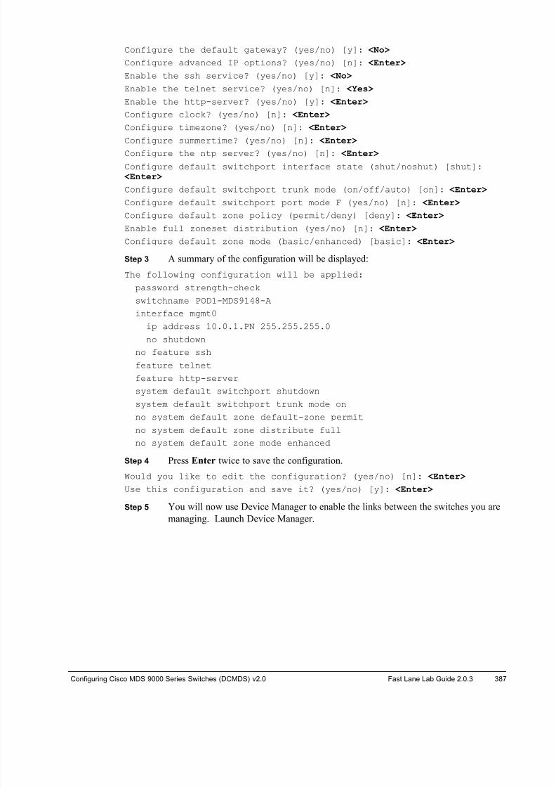
8/18/2019 FL_DCMDS_2.0.3_LG(1).pdf
http://slidepdf.com/reader/full/fldcmds203lg1pdf 387/482
Configuring Cisco MDS 9000 Series Switches (DCMDS) v2.0 Fast Lane Lab Guide 2.0.3 387
Configure the default gateway? (yes/no) [y]: <No>
Configure advanced IP options? (yes/no) [n]: <Enter>
Enable the ssh service? (yes/no) [y]: <No>
Enable the telnet service? (yes/no) [n]: <Yes>
Enable the http-server? (yes/no) [y]: <Enter>
Configure clock? (yes/no) [n]: <Enter>
Configure timezone? (yes/no) [n]: <Enter>
Configure summertime? (yes/no) [n]: <Enter>
Configure the ntp server? (yes/no) [n]: <Enter>
Configure default switchport interface state (shut/noshut) [shut]: <Enter>
Configure default switchport trunk mode (on/off/auto) [on]: <Enter>
Configure default switchport port mode F (yes/no) [n]: <Enter>
Configure default zone policy (permit/deny) [deny]: <Enter>
Enable full zoneset distribution (yes/no) [n]: <Enter>
Configure default zone mode (basic/enhanced) [basic]: <Enter>
Step 3 A summary of the configuration will be displayed:
The following configuration will be applied:password strength-check
switchname POD1-MDS9148-A
interface mgmt0
ip address 10.0.1.PN 255.255.255.0
no shutdown
no feature ssh
feature telnet
feature http-server
system default switchport shutdown
system default switchport trunk mode on
no system default zone default-zone permit
no system default zone distribute full
no system default zone mode enhanced
Step 4 Press Enter twice to save the configuration.
Would you like to edit the configuration? (yes/no) [n]: <Enter>
Use this configuration and save it? (yes/no) [y]: <Enter>
Step 5 You will now use Device Manager to enable the links between the switches you are
managing. Launch Device Manager.

8/18/2019 FL_DCMDS_2.0.3_LG(1).pdf
http://slidepdf.com/reader/full/fldcmds203lg1pdf 388/482
388 Configuring Cisco MDS 9000 Series Switches (DCMDS) v2.0 © 2014 Fast Lane and Cisco Systems, Inc.
Step 6 Connect to your 9148, enter the password 1234QWer, then click Open.
Step 7 Note all ports are (shut)down.
Step 8 Enable interfaces FC1/1 on the 9148s as an F port andFC1/11 and FC1/12 as an E port. Since all ports are autosensing by default,
enabling them is enough.
Note The 9222i has been preconfigured.
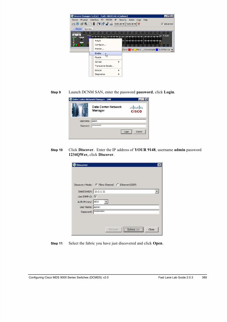
8/18/2019 FL_DCMDS_2.0.3_LG(1).pdf
http://slidepdf.com/reader/full/fldcmds203lg1pdf 389/482
Configuring Cisco MDS 9000 Series Switches (DCMDS) v2.0 Fast Lane Lab Guide 2.0.3 389
Step 9 Launch DCNM SAN, enter the password password, click Login.
Step 10 Click Discover. Enter the IP address of YOUR 9148, username admin password
1234QWer, click Discover.
Step 11 Select the fabric you have just discovered and click Open.
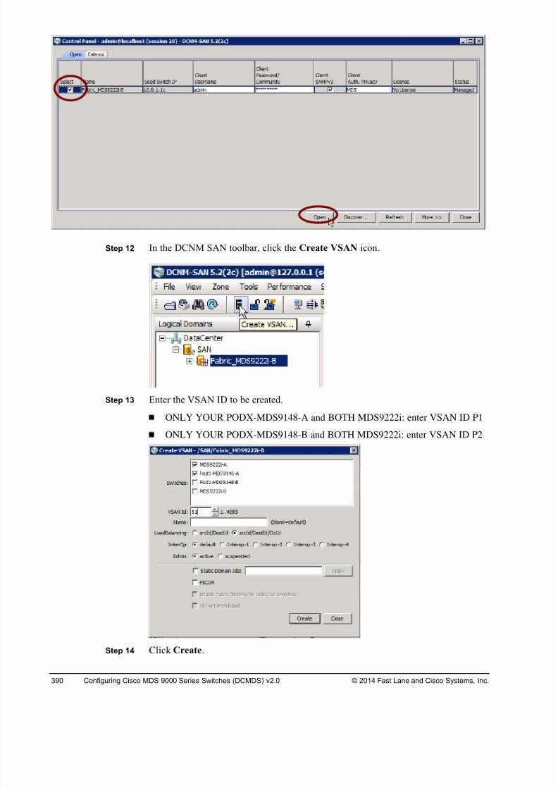
8/18/2019 FL_DCMDS_2.0.3_LG(1).pdf
http://slidepdf.com/reader/full/fldcmds203lg1pdf 390/482
390 Configuring Cisco MDS 9000 Series Switches (DCMDS) v2.0 © 2014 Fast Lane and Cisco Systems, Inc.
Step 12 In the DCNM SAN toolbar, click the Create VSAN icon.
Step 13 Enter the VSAN ID to be created.
ONLY YOUR PODX-MDS9148-A and BOTH MDS9222i: enter VSAN ID P1
ONLY YOUR PODX-MDS9148-B and BOTH MDS9222i: enter VSAN ID P2
Step 14 Click Create.

8/18/2019 FL_DCMDS_2.0.3_LG(1).pdf
http://slidepdf.com/reader/full/fldcmds203lg1pdf 391/482
Configuring Cisco MDS 9000 Series Switches (DCMDS) v2.0 Fast Lane Lab Guide 2.0.3 391
Step 15 In the Physical Attributes pane, select the Switches > Interfaces > FC Physical
placeholder.
Step 16 If you are configuring Fabric A assign ports to VSANs on POD#-MDS9148-A and
MDS9222i-BAssign VSAN interface membership in the Port VSAN column:
! POD#-MDS9148-A: VSAN P1 members = fc1/1
! JBOD Disks on 9222i-B FOR YOUR POD ONLY:
Pod number 9222i-B
Port
VSAN
1 fc1/4 11
2 fc1/8 21
3 fc1/12 31
4 fc1/16 41
DO NOT ENABLE/CHANGE ANY OTHER PORT on the 9222i
Step 17 If you are configuring Fabric B assign ports to VSANs on POD#-MDS9148-A and
MDS9222i-A
Assign VSAN interface membership in the Port VSAN column:
! POD#-MDS9148-B: VSAN P2 members = fc1/1
! JBOD Disks on 9222i-A FOR YOUR POD ONLY:
Pod number 9222i-A
Port
VSAN
1 fc1/4 12
2 fc1/8 22
3 fc1/12 32
4 fc1/16 42
DO NOT ENABLE/CHANGE ANY OTHER PORT on the 9222i
Step 16 Do not forget to Click the Apply Changes button.
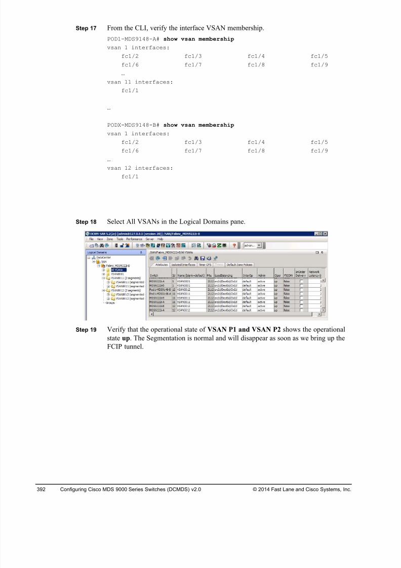
8/18/2019 FL_DCMDS_2.0.3_LG(1).pdf
http://slidepdf.com/reader/full/fldcmds203lg1pdf 392/482
392 Configuring Cisco MDS 9000 Series Switches (DCMDS) v2.0 © 2014 Fast Lane and Cisco Systems, Inc.
Step 17 From the CLI, verify the interface VSAN membership.
POD1-MDS9148-A# show vsan membership
vsan 1 interfaces:
fc1/2 fc1/3 fc1/4 fc1/5
fc1/6 fc1/7 fc1/8 fc1/9
…
vsan 11 interfaces:
fc1/1
…
PODX-MDS9148-B# show vsan membership
vsan 1 interfaces:
fc1/2 fc1/3 fc1/4 fc1/5
fc1/6 fc1/7 fc1/8 fc1/9
…
vsan 12 interfaces:
fc1/1
Step 18 Select All VSANs in the Logical Domains pane.
Step 19 Verify that the operational state of VSAN P1 and VSAN P2 shows the operational
state up. The Segmentation is normal and will disappear as soon as we bring up the
FCIP tunnel.
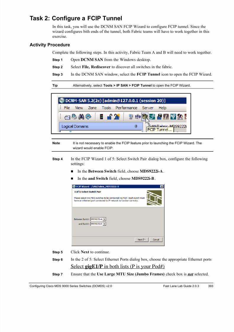
8/18/2019 FL_DCMDS_2.0.3_LG(1).pdf
http://slidepdf.com/reader/full/fldcmds203lg1pdf 393/482
Configuring Cisco MDS 9000 Series Switches (DCMDS) v2.0 Fast Lane Lab Guide 2.0.3 393
Task 2: Configure a FCIP Tunnel
In this task, you will use the DCNM SAN FCIP Wizard to configure FCIP tunnel. Since the
wizard configures bith ends of the tunnel, both Fabric teams will have to work together in this
exercise.
Activity Procedure
Complete the following steps. In this activity, Fabric Team A and B will need to work together.
Step 1 Open DCNM SAN from the Windows desktop.
Step 2 Select File, Rediscover to discover all switches in the fabric.
Step 3 In the DCNM SAN window, select the FCIP Tunnel icon to open the FCIP Wizard.
Tip Alternatively, select Tools > IP SAN > FCIP Tunnel to open the FCIP Wizard.
Note It is not necessary to enable the FCIP feature prior to launching the FCIP Wizard. The
wizard would enable FCIP.
Step 4 In the FCIP Wizard 1 of 5: Select Switch Pair dialog box, configure the following
settings:
! In the Between Switch field, choose MDS9222i-A.
! In the and Switch field, choose MDS9222i-B.
Step 5 Click Next to continue.
Step 6 In the 2 of 5: Select Ethernet Ports dialog box, choose the appropriate Ethernet ports
Select gigE1/P in both lists (P is your Pod#)
Step 7 Ensure that the Use Large MTU Size (Jumbo Frames) check box is not selected.
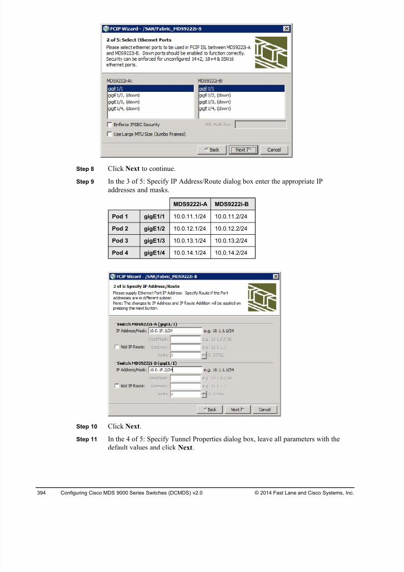
8/18/2019 FL_DCMDS_2.0.3_LG(1).pdf
http://slidepdf.com/reader/full/fldcmds203lg1pdf 394/482
394 Configuring Cisco MDS 9000 Series Switches (DCMDS) v2.0 © 2014 Fast Lane and Cisco Systems, Inc.
Step 8 Click Next to continue.
Step 9 In the 3 of 5: Specify IP Address/Route dialog box enter the appropriate IP
addresses and masks.
MDS9222i-A MDS9222i-B
Pod 1 gigE1/1 10.0.11.1/24 10.0.11.2/24
Pod 2 gigE1/2 10.0.12.1/24 10.0.12.2/24
Pod 3 gigE1/3 10.0.13.1/24 10.0.13.2/24
Pod 4 gigE1/4 10.0.14.1/24 10.0.14.2/24
Step 10 Click Next.
Step 11 In the 4 of 5: Specify Tunnel Properties dialog box, leave all parameters with the
default values and click Next.
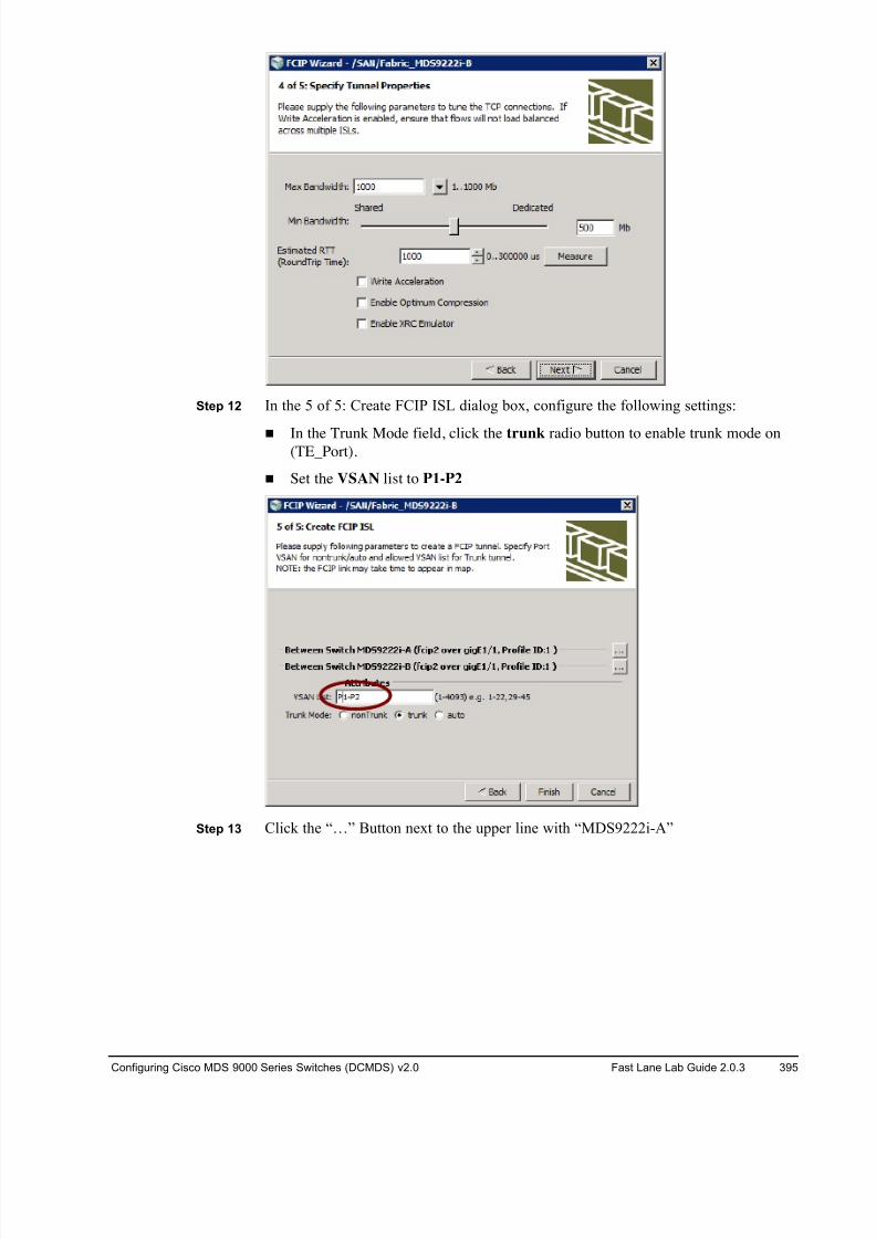
8/18/2019 FL_DCMDS_2.0.3_LG(1).pdf
http://slidepdf.com/reader/full/fldcmds203lg1pdf 395/482
Configuring Cisco MDS 9000 Series Switches (DCMDS) v2.0 Fast Lane Lab Guide 2.0.3 395
Step 12 In the 5 of 5: Create FCIP ISL dialog box, configure the following settings:
! In the Trunk Mode field, click the trunk radio button to enable trunk mode on(TE_Port).
! Set the VSAN list to P1-P2
Step 13 Click the “…” Button next to the upper line with “MDS9222i-A”
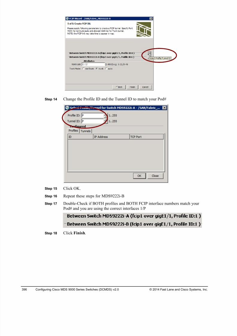
8/18/2019 FL_DCMDS_2.0.3_LG(1).pdf
http://slidepdf.com/reader/full/fldcmds203lg1pdf 396/482
396 Configuring Cisco MDS 9000 Series Switches (DCMDS) v2.0 © 2014 Fast Lane and Cisco Systems, Inc.
Step 14 Change the Profile ID and the Tunnel ID to match your Pod#
Step 15 Click OK.
Step 16 Repeat these steps for MDS9222i-B
Step 17 Double-Check if BOTH profiles and BOTH FCIP interface numbers match your
Pod# and you are using the correct interfaces 1/P
Step 18 Click Finish.
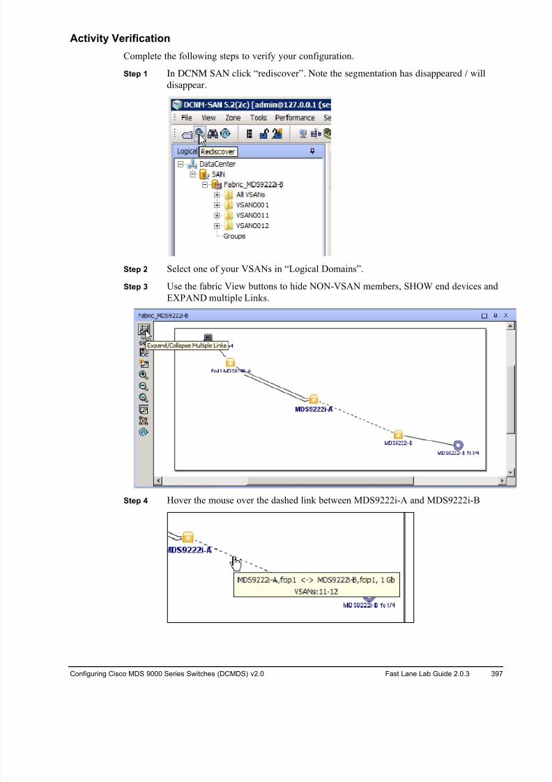
8/18/2019 FL_DCMDS_2.0.3_LG(1).pdf
http://slidepdf.com/reader/full/fldcmds203lg1pdf 397/482
Configuring Cisco MDS 9000 Series Switches (DCMDS) v2.0 Fast Lane Lab Guide 2.0.3 397
Activity Verification
Complete the following steps to verify your configuration.
Step 1 In DCNM SAN click “rediscover”. Note the segmentation has disappeared / will
disappear.
Step 2 Select one of your VSANs in “Logical Domains”.
Step 3 Use the fabric View buttons to hide NON-VSAN members, SHOW end devices and
EXPAND multiple Links.
Step 4 Hover the mouse over the dashed link between MDS9222i-A and MDS9222i-B
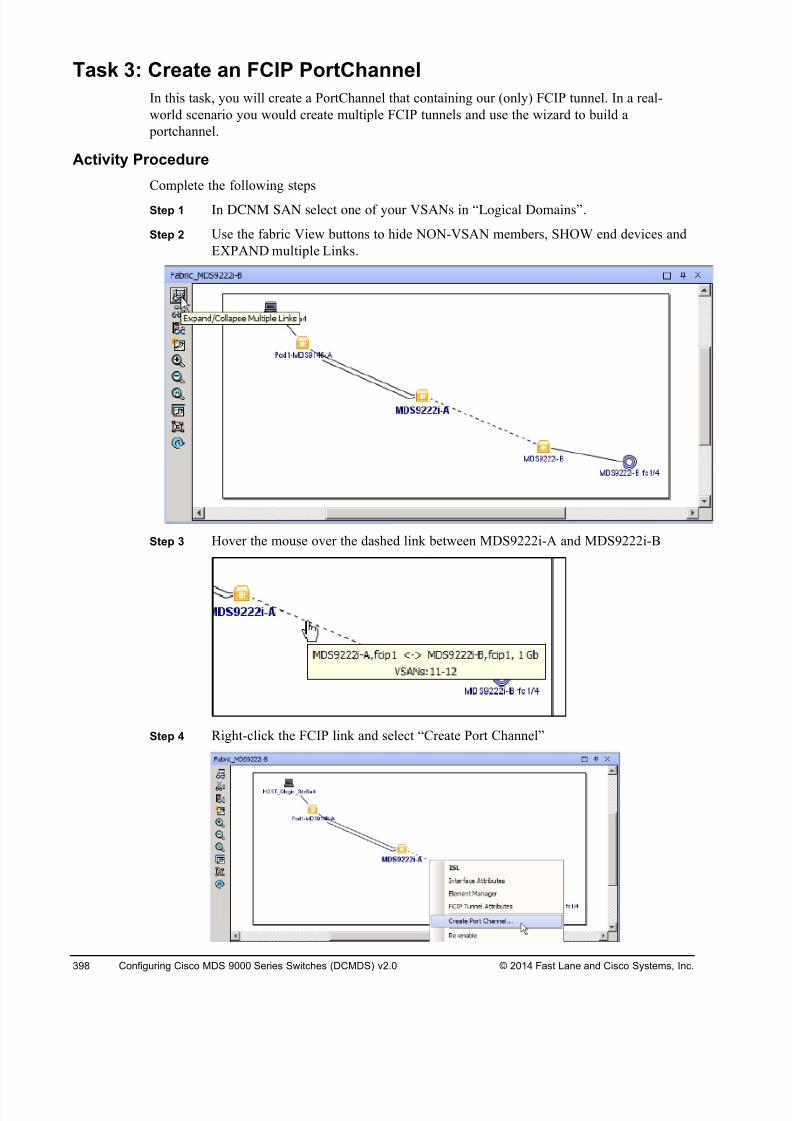
8/18/2019 FL_DCMDS_2.0.3_LG(1).pdf
http://slidepdf.com/reader/full/fldcmds203lg1pdf 398/482
398 Configuring Cisco MDS 9000 Series Switches (DCMDS) v2.0 © 2014 Fast Lane and Cisco Systems, Inc.
Task 3: Create an FCIP PortChannel
In this task, you will create a PortChannel that containing our (only) FCIP tunnel. In a real-
world scenario you would create multiple FCIP tunnels and use the wizard to build a
portchannel.
Activity Procedure
Complete the following steps
Step 1 In DCNM SAN select one of your VSANs in “Logical Domains”.
Step 2 Use the fabric View buttons to hide NON-VSAN members, SHOW end devices and
EXPAND multiple Links.
Step 3 Hover the mouse over the dashed link between MDS9222i-A and MDS9222i-B
Step 4 Right-click the FCIP link and select “Create Port Channel”
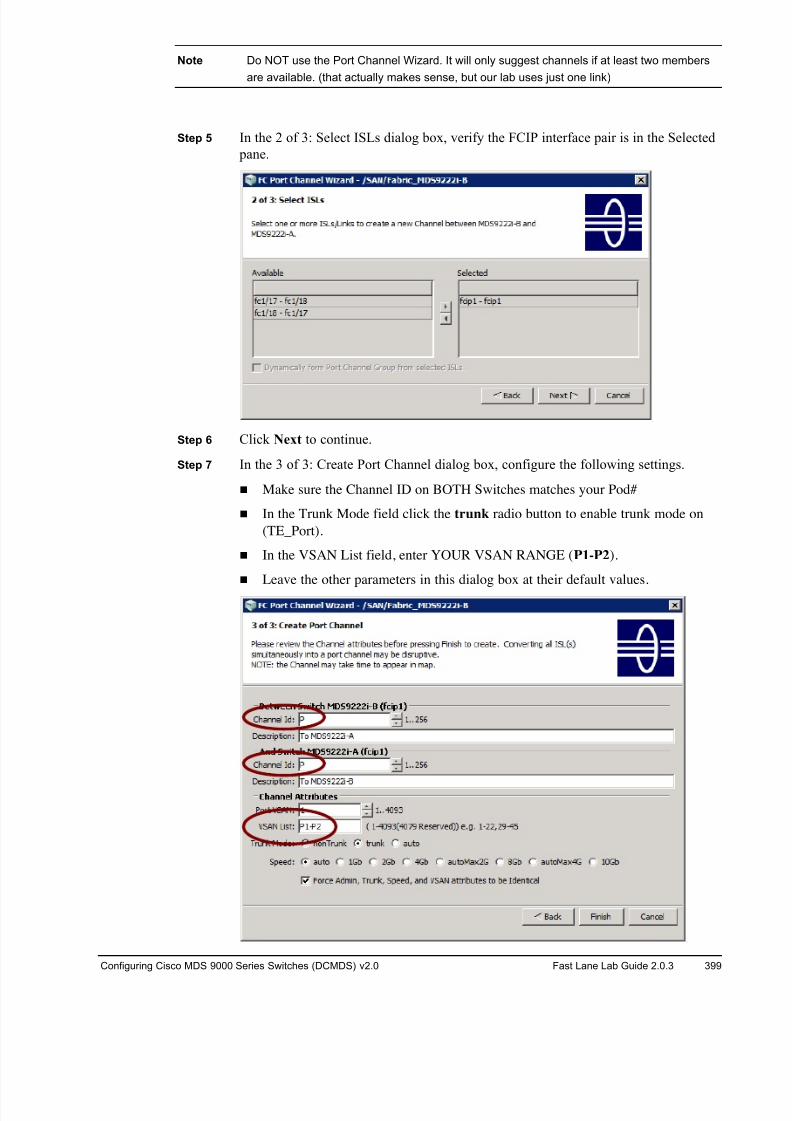
8/18/2019 FL_DCMDS_2.0.3_LG(1).pdf
http://slidepdf.com/reader/full/fldcmds203lg1pdf 399/482
Configuring Cisco MDS 9000 Series Switches (DCMDS) v2.0 Fast Lane Lab Guide 2.0.3 399
Note Do NOT use the Port Channel Wizard. It will only suggest channels if at least two members
are available. (that actually makes sense, but our lab uses just one link)
Step 5 In the 2 of 3: Select ISLs dialog box, verify the FCIP interface pair is in the Selected
pane.
Step 6 Click Next to continue.
Step 7 In the 3 of 3: Create Port Channel dialog box, configure the following settings.
! Make sure the Channel ID on BOTH Switches matches your Pod#
! In the Trunk Mode field click the trunk radio button to enable trunk mode on
(TE_Port).
! In the VSAN List field, enter YOUR VSAN RANGE (P1-P2).
! Leave the other parameters in this dialog box at their default values.
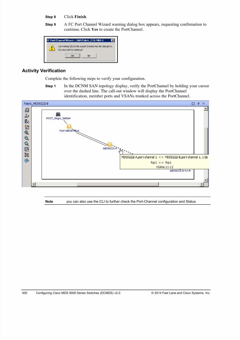
8/18/2019 FL_DCMDS_2.0.3_LG(1).pdf
http://slidepdf.com/reader/full/fldcmds203lg1pdf 400/482
400 Configuring Cisco MDS 9000 Series Switches (DCMDS) v2.0 © 2014 Fast Lane and Cisco Systems, Inc.
Step 8 Click Finish.
Step 9 A FC Port Channel Wizard warning dialog box appears, requesting confirmation to
continue. Click Yes to create the PortChannel.
Activity Verification
Complete the following steps to verify your configuration.
Step 1 In the DCNM SAN topology display, verify the PortChannel by holding your cursor
over the dashed line. The call-out window will display the PortChannel
identification, member ports and VSANs trunked across the PortChannel.
Note you can also use the CLI to further check the Port-Channel configuration and Status.
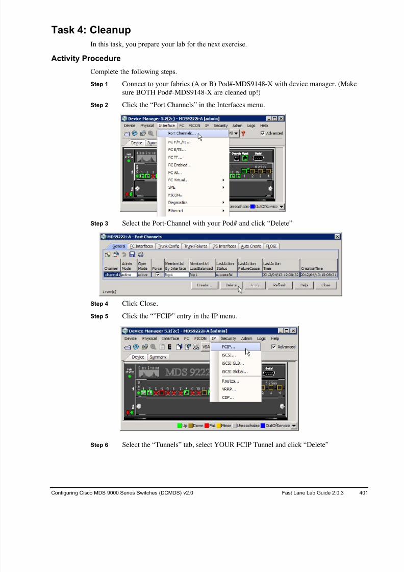
8/18/2019 FL_DCMDS_2.0.3_LG(1).pdf
http://slidepdf.com/reader/full/fldcmds203lg1pdf 401/482
Configuring Cisco MDS 9000 Series Switches (DCMDS) v2.0 Fast Lane Lab Guide 2.0.3 401
Task 4: Cleanup
In this task, you prepare your lab for the next exercise.
Activity Procedure
Complete the following steps.
Step 1 Connect to your fabrics (A or B) Pod#-MDS9148-X with device manager. (Make
sure BOTH Pod#-MDS9148-X are cleaned up!)
Step 2 Click the “Port Channels” in the Interfaces menu.
Step 3 Select the Port-Channel with your Pod# and click “Delete”
Step 4 Click Close.
Step 5 Click the “”FCIP” entry in the IP menu.
Step 6 Select the “Tunnels” tab, select YOUR FCIP Tunnel and click “Delete”
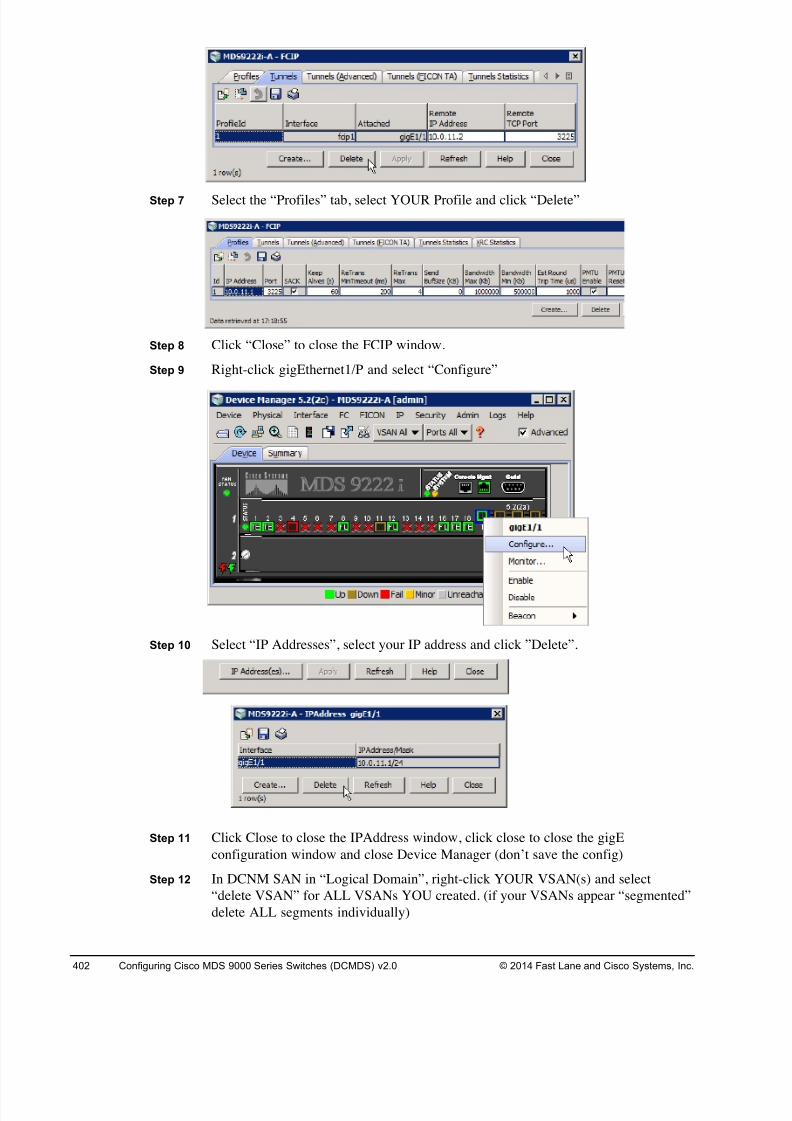
8/18/2019 FL_DCMDS_2.0.3_LG(1).pdf
http://slidepdf.com/reader/full/fldcmds203lg1pdf 402/482
402 Configuring Cisco MDS 9000 Series Switches (DCMDS) v2.0 © 2014 Fast Lane and Cisco Systems, Inc.
Step 7 Select the “Profiles” tab, select YOUR Profile and click “Delete”
Step 8 Click “Close” to close the FCIP window.
Step 9 Right-click gigEthernet1/P and select “Configure”
Step 10 Select “IP Addresses”, select your IP address and click ”Delete”.
Step 11 Click Close to close the IPAddress window, click close to close the gigE
configuration window and close Device Manager (don’t save the config)
Step 12 In DCNM SAN in “Logical Domain”, right-click YOUR VSAN(s) and select
“delete VSAN” for ALL VSANs YOU created. (if your VSANs appear “segmented”
delete ALL segments individually)
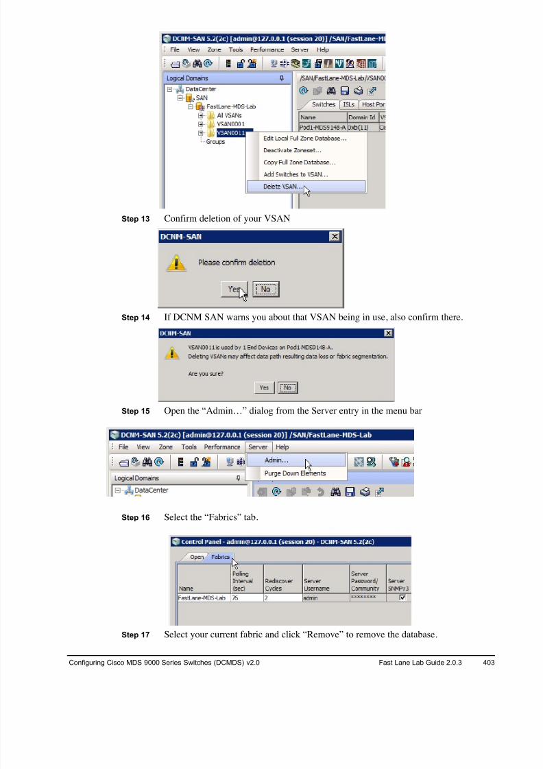
8/18/2019 FL_DCMDS_2.0.3_LG(1).pdf
http://slidepdf.com/reader/full/fldcmds203lg1pdf 403/482
Configuring Cisco MDS 9000 Series Switches (DCMDS) v2.0 Fast Lane Lab Guide 2.0.3 403
Step 13 Confirm deletion of your VSAN
Step 14 If DCNM SAN warns you about that VSAN being in use, also confirm there.
Step 15 Open the “Admin…” dialog from the Server entry in the menu bar
Step 16 Select the “Fabrics” tab.
Step 17 Select your current fabric and click “Remove” to remove the database.
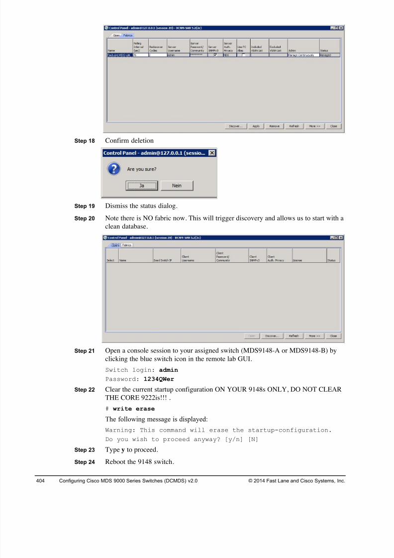
8/18/2019 FL_DCMDS_2.0.3_LG(1).pdf
http://slidepdf.com/reader/full/fldcmds203lg1pdf 404/482
404 Configuring Cisco MDS 9000 Series Switches (DCMDS) v2.0 © 2014 Fast Lane and Cisco Systems, Inc.
Step 18 Confirm deletion
Step 19 Dismiss the status dialog.
Step 20 Note there is NO fabric now. This will trigger discovery and allows us to start with a
clean database.
Step 21 Open a console session to your assigned switch (MDS9148-A or MDS9148-B) by
clicking the blue switch icon in the remote lab GUI.
Switch login: admin
Password: 1234QWer
Step 22 Clear the current startup configuration ON YOUR 9148s ONLY, DO NOT CLEARTHE CORE 9222is!!! .
# write erase
The following message is displayed:
Warning: This command will erase the startup-configuration.
Do you wish to proceed anyway? [y/n] [N]
Step 23 Type y to proceed.
Step 24 Reboot the 9148 switch.

8/18/2019 FL_DCMDS_2.0.3_LG(1).pdf
http://slidepdf.com/reader/full/fldcmds203lg1pdf 405/482
Configuring Cisco MDS 9000 Series Switches (DCMDS) v2.0 Fast Lane Lab Guide 2.0.3 405
# reload
This command will reboot the system. (y/n)?
Step 25 Type y to proceed.
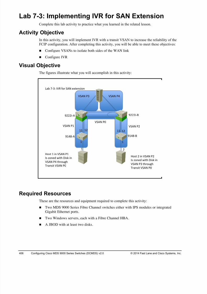
8/18/2019 FL_DCMDS_2.0.3_LG(1).pdf
http://slidepdf.com/reader/full/fldcmds203lg1pdf 406/482
406 Configuring Cisco MDS 9000 Series Switches (DCMDS) v2.0 © 2014 Fast Lane and Cisco Systems, Inc.
Lab 7-3: Implementing IVR for SAN Extension Complete this lab activity to practice what you learned in the related lesson.
Activity Objective
In this activity, you will implement IVR with a transit VSAN to increase the reliability of the
FCIP configuration. After completing this activity, you will be able to meet these objectives:
! Configure VSANs to isolate both sides of the WAN link
! Configure IVR
Visual Objective
The figures illustrate what you will accomplish in this activity:
Required Resources
These are the resources and equipment required to complete this activity:
! Two MDS 9000 Series Fibre Channel switches either with IPS modules or integrated
Gigabit Ethernet ports.
! Two Windows servers, each with a Fibre Channel HBA.
! A JBOD with at least two disks.
! !
!# !! !#!!
! #
$!%&'( $!%&')
$###*'( $###*')
+,- .'/0 123 456 7(8 9:;9<=*5<
27(8 >! 27(8 >#
27(8 >?
27(8 >/ 27(8 >%
@5=; ! *< 27(8 >!1= A5<9B C*;D E*=F *<
27(8 >% ;D65GHD
I6,<=*; 27(8 >?
@5=; # *< 27(8 >#
1= A5<9B C*;D E*=F *<
27(8 >/ ;D65GHD
I6,<=*; 27(8 >?
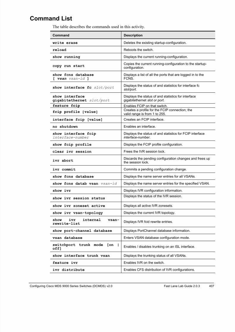
8/18/2019 FL_DCMDS_2.0.3_LG(1).pdf
http://slidepdf.com/reader/full/fldcmds203lg1pdf 407/482
Configuring Cisco MDS 9000 Series Switches (DCMDS) v2.0 Fast Lane Lab Guide 2.0.3 407
Command List
The table describes the commands used in this activity.
Command Description
write erase Deletes the existing startup-configuration.
reload Reboots the switch.
show running Displays the current running-configuration.
copy run startCopies the current running-configuration to the startup-configuration.
show fcns database[ vsan vsan-id ]
Displays a list of all the ports that are logged in to theFCNS.
show interface fc slot/port Displays the status of and statistics for interface fc slot/port.
show interfacegigabitethernet slot/port
Displays the status of and statistics for interfacegigabitethernet slot or port.
feature fcip Enables FCIP on that switch.
fcip profile [value]Creates a profile for the FCIP connection; thevalid range is from 1 to 255.
interface fcip [value] Creates an FCIP interface.
no shutdown Enables an interface.
show interface fcipinterface-number
Displays the status of and statistics for FCIP interfaceinterface-number.
show fcip profile Displays the FCIP profile configuration.
clear ivr session Frees the IVR session lock.
ivr abortDiscards the pending configuration changes and frees upthe session lock.
ivr commit Commits a pending configuration change.
show fcns database Displays the name server entries for all VSANs.
show fcns datab vsan vsan-id Displays the name server entries for the specified VSAN.
show ivr Displays IVR configuration information.
show ivr session statusDisplays the status of the IVR session.
show ivr zoneset active Displays all active IVR zonesets.
show ivr vsan-topology Displays the current IVR topology.
show ivr internal vsan-rewrite-list
Displays IVR fcid rewrite entries.
show port-channel database Displays PortChannel database information.
vsan database Enters VSAN database configuration mode.
switchport trunk mode [on |off]
Enables / disables trunking on an ISL interface.
show interface trunk vsan Displays the trunking status of all VSANs.
feature ivr Enables IVR on the switch.
ivr distribute Enables CFS distribution of IVR configurations.
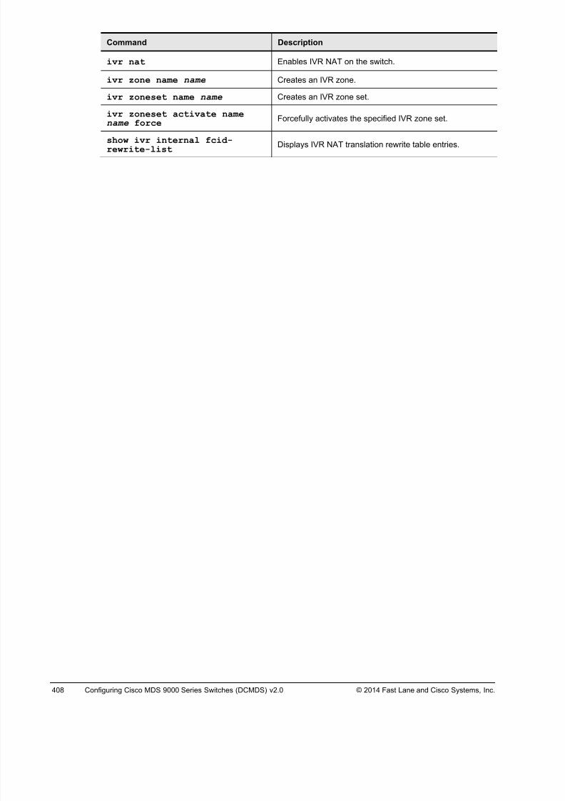
8/18/2019 FL_DCMDS_2.0.3_LG(1).pdf
http://slidepdf.com/reader/full/fldcmds203lg1pdf 408/482
408 Configuring Cisco MDS 9000 Series Switches (DCMDS) v2.0 © 2014 Fast Lane and Cisco Systems, Inc.
Command Description
ivr nat Enables IVR NAT on the switch.
ivr zone name name Creates an IVR zone.
ivr zoneset name name Creates an IVR zone set.
ivr zoneset activate namename force Forcefully activates the specified IVR zone set.
show ivr internal fcid-rewrite-list
Displays IVR NAT translation rewrite table entries.
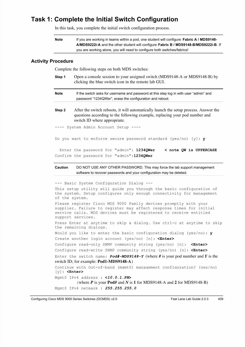
8/18/2019 FL_DCMDS_2.0.3_LG(1).pdf
http://slidepdf.com/reader/full/fldcmds203lg1pdf 409/482
Configuring Cisco MDS 9000 Series Switches (DCMDS) v2.0 Fast Lane Lab Guide 2.0.3 409
Task 1: Complete the Initial Switch Configuration
In this task, you complete the initial switch configuration process.
Note If you are working in teams within a pod, one student will configure Fabric A / MDS9148-
A/MDS9222i-A and the other student will configure Fabric B / MDS9148-B/MDS9222i-B. If
you are working alone, you will need to configure both switches/fabrics!
Activity Procedure
Complete the following steps on both MDS switches:
Step 1 Open a console session to your assigned switch (MDS9148-A or MDS9148-B) by
clicking the blue switch icon in the remote lab GUI.
Note If the switch asks for username and password at this step log in with user “admin” and
password “1234QWer”, erase the configuration and reboot.
Step 2 After the switch reboots, it will automatically launch the setup process. Answer the
questions according to the following example, replacing your pod number and
switch ID where appropriate.---- System Admin Account Setup ----
Do you want to enforce secure password standard (yes/no) [y]: y
Enter the password for "admin": 1234QWer < note QW is UPPERCASE
Confirm the password for "admin":1234QWer
Caution DO NOT USE ANY OTHER PASSWORD. This may force the lab support management
software to recover passwords and your configuration may be deleted.
--- Basic System Configuration Dialog ---
This setup utility will guide you through the basic configuration ofthe system. Setup configures only enough connectivity for managementof the system.
Please register Cisco MDS 9000 Family devices promptly with yoursupplier. Failure to register may affect response times for initialservice calls. MDS devices must be registered to receive entitledsupport services.
Press Enter at anytime to skip a dialog. Use ctrl-c at anytime to skipthe remaining dialogs.
Would you like to enter the basic configuration dialog (yes/no): y
Create another login account (yes/no) [n]: <Enter>
Configure read-only SNMP community string (yes/no) [n]: <Enter>
Configure read-write SNMP community string (yes/no) [n]: <Enter>
Enter the switch name: Pod#-MDS9148-Y (where # is your pod number and Y is the
switch ID; for example: Pod1-MDS9148-A)
Continue with Out-of-band (mgmt0) management configuration? (yes/no)[y]: <Enter>
Mgmt0 IPv4 address : <10.0.1.PN >
(where P is your Pod# and N is 1 for MDS9148-A and 2 for MDS9148-B)
Mgmt0 IPv4 netmask : 255.255.255.0
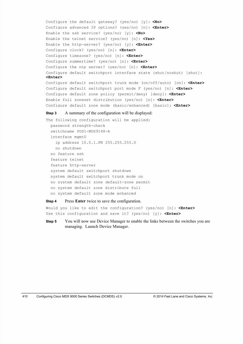
8/18/2019 FL_DCMDS_2.0.3_LG(1).pdf
http://slidepdf.com/reader/full/fldcmds203lg1pdf 410/482
410 Configuring Cisco MDS 9000 Series Switches (DCMDS) v2.0 © 2014 Fast Lane and Cisco Systems, Inc.
Configure the default gateway? (yes/no) [y]: <No>
Configure advanced IP options? (yes/no) [n]: <Enter>
Enable the ssh service? (yes/no) [y]: <No>
Enable the telnet service? (yes/no) [n]: <Yes>
Enable the http-server? (yes/no) [y]: <Enter>
Configure clock? (yes/no) [n]: <Enter>
Configure timezone? (yes/no) [n]: <Enter>
Configure summertime? (yes/no) [n]: <Enter>
Configure the ntp server? (yes/no) [n]: <Enter>
Configure default switchport interface state (shut/noshut) [shut]: <Enter>
Configure default switchport trunk mode (on/off/auto) [on]: <Enter>
Configure default switchport port mode F (yes/no) [n]: <Enter>
Configure default zone policy (permit/deny) [deny]: <Enter>
Enable full zoneset distribution (yes/no) [n]: <Enter>
Configure default zone mode (basic/enhanced) [basic]: <Enter>
Step 3 A summary of the configuration will be displayed:
The following configuration will be applied:password strength-check
switchname POD1-MDS9148-A
interface mgmt0
ip address 10.0.1.PN 255.255.255.0
no shutdown
no feature ssh
feature telnet
feature http-server
system default switchport shutdown
system default switchport trunk mode on
no system default zone default-zone permit
no system default zone distribute full
no system default zone mode enhanced
Step 4 Press Enter twice to save the configuration.
Would you like to edit the configuration? (yes/no) [n]: <Enter>
Use this configuration and save it? (yes/no) [y]: <Enter>
Step 5 You will now use Device Manager to enable the links between the switches you are
managing. Launch Device Manager.
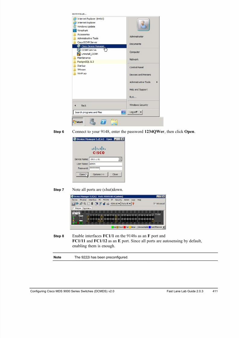
8/18/2019 FL_DCMDS_2.0.3_LG(1).pdf
http://slidepdf.com/reader/full/fldcmds203lg1pdf 411/482
Configuring Cisco MDS 9000 Series Switches (DCMDS) v2.0 Fast Lane Lab Guide 2.0.3 411
Step 6 Connect to your 9148, enter the password 1234QWer, then click Open.
Step 7 Note all ports are (shut)down.
Step 8 Enable interfaces FC1/1 on the 9148s as an F port andFC1/11 and FC1/12 as an E port. Since all ports are autosensing by default,
enabling them is enough.
Note The 9222i has been preconfigured.
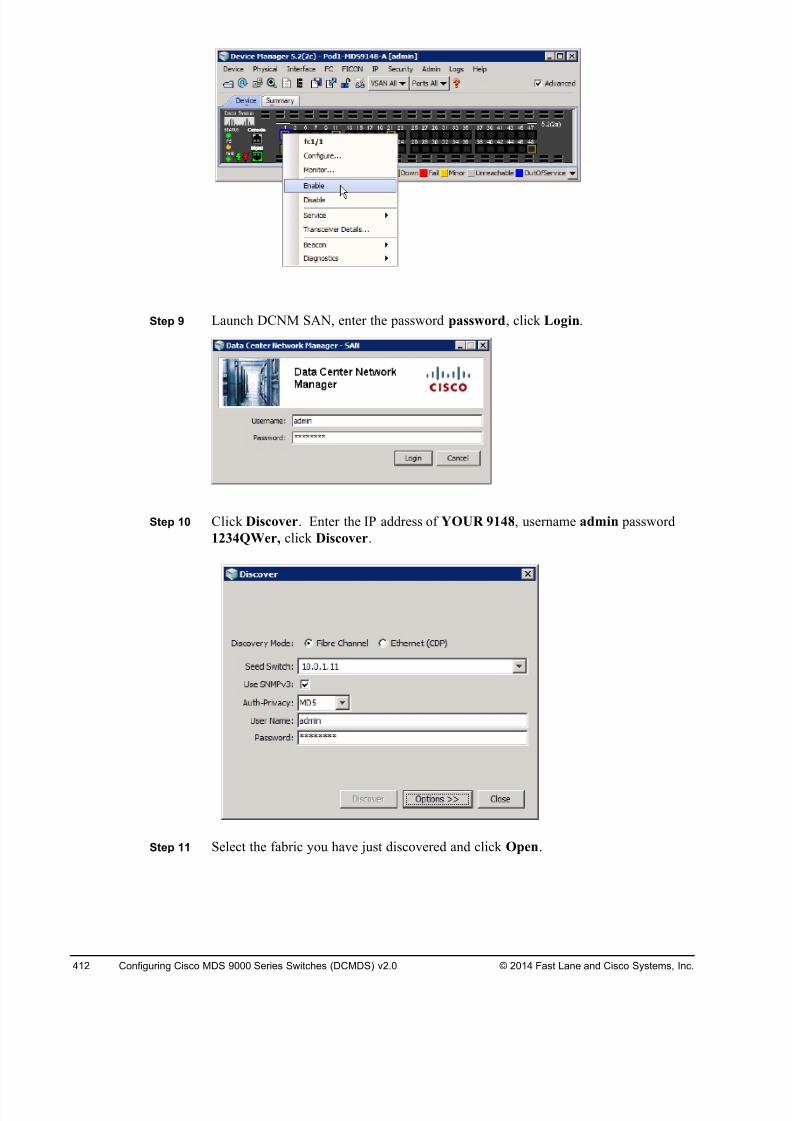
8/18/2019 FL_DCMDS_2.0.3_LG(1).pdf
http://slidepdf.com/reader/full/fldcmds203lg1pdf 412/482
412 Configuring Cisco MDS 9000 Series Switches (DCMDS) v2.0 © 2014 Fast Lane and Cisco Systems, Inc.
Step 9 Launch DCNM SAN, enter the password password, click Login.
Step 10 Click Discover. Enter the IP address of YOUR 9148, username admin password
1234QWer, click Discover.
Step 11 Select the fabric you have just discovered and click Open.
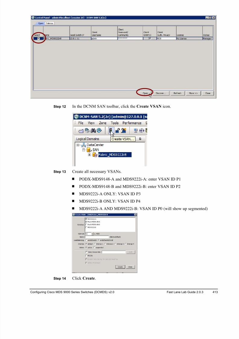
8/18/2019 FL_DCMDS_2.0.3_LG(1).pdf
http://slidepdf.com/reader/full/fldcmds203lg1pdf 413/482
Configuring Cisco MDS 9000 Series Switches (DCMDS) v2.0 Fast Lane Lab Guide 2.0.3 413
Step 12 In the DCNM SAN toolbar, click the Create VSAN icon.
Step 13 Create all necessary VSANs.
PODX-MDS9148-A and MDS9222i-A: enter VSAN ID P1
PODX-MDS9148-B and MDS9222i-B: enter VSAN ID P2
MDS9222i-A ONLY: VSAN ID P3
MDS9222i-B ONLY: VSAN ID P4
MDS9222i-A AND MDS9222i-B: VSAN ID P0 (will show up segmented)
Step 14 Click Create.
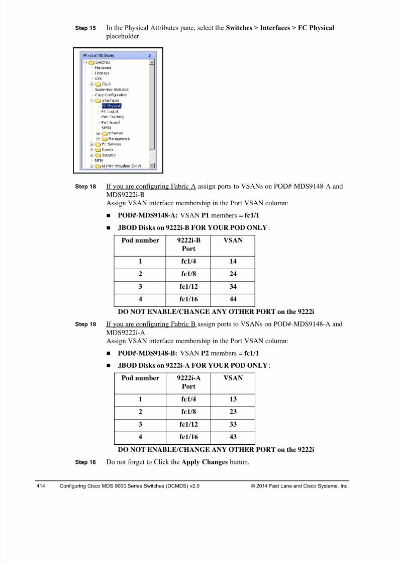
8/18/2019 FL_DCMDS_2.0.3_LG(1).pdf
http://slidepdf.com/reader/full/fldcmds203lg1pdf 414/482
414 Configuring Cisco MDS 9000 Series Switches (DCMDS) v2.0 © 2014 Fast Lane and Cisco Systems, Inc.
Step 15 In the Physical Attributes pane, select the Switches > Interfaces > FC Physical
placeholder.
Step 18 If you are configuring Fabric A assign ports to VSANs on POD#-MDS9148-A and
MDS9222i-BAssign VSAN interface membership in the Port VSAN column:
! POD#-MDS9148-A: VSAN P1 members = fc1/1
! JBOD Disks on 9222i-B FOR YOUR POD ONLY:
Pod number 9222i-B
Port
VSAN
1 fc1/4 14
2 fc1/8 24
3 fc1/12 34
4 fc1/16 44
DO NOT ENABLE/CHANGE ANY OTHER PORT on the 9222i
Step 19 If you are configuring Fabric B assign ports to VSANs on POD#-MDS9148-A and
MDS9222i-A
Assign VSAN interface membership in the Port VSAN column:
! POD#-MDS9148-B: VSAN P2 members = fc1/1
! JBOD Disks on 9222i-A FOR YOUR POD ONLY:
Pod number 9222i-A
Port
VSAN
1 fc1/4 13
2 fc1/8 23
3 fc1/12 33
4 fc1/16 43
DO NOT ENABLE/CHANGE ANY OTHER PORT on the 9222i
Step 16 Do not forget to Click the Apply Changes button.
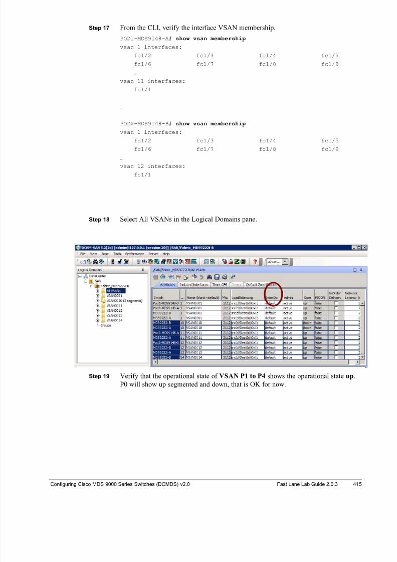
8/18/2019 FL_DCMDS_2.0.3_LG(1).pdf
http://slidepdf.com/reader/full/fldcmds203lg1pdf 415/482
Configuring Cisco MDS 9000 Series Switches (DCMDS) v2.0 Fast Lane Lab Guide 2.0.3 415
Step 17 From the CLI, verify the interface VSAN membership.
POD1-MDS9148-A# show vsan membership
vsan 1 interfaces:
fc1/2 fc1/3 fc1/4 fc1/5
fc1/6 fc1/7 fc1/8 fc1/9
…
vsan 11 interfaces:
fc1/1
…
PODX-MDS9148-B# show vsan membership
vsan 1 interfaces:
fc1/2 fc1/3 fc1/4 fc1/5
fc1/6 fc1/7 fc1/8 fc1/9
…
vsan 12 interfaces:
fc1/1
Step 18 Select All VSANs in the Logical Domains pane.
Step 19 Verify that the operational state of VSAN P1 to P4 shows the operational state up.
P0 will show up segmented and down, that is OK for now.
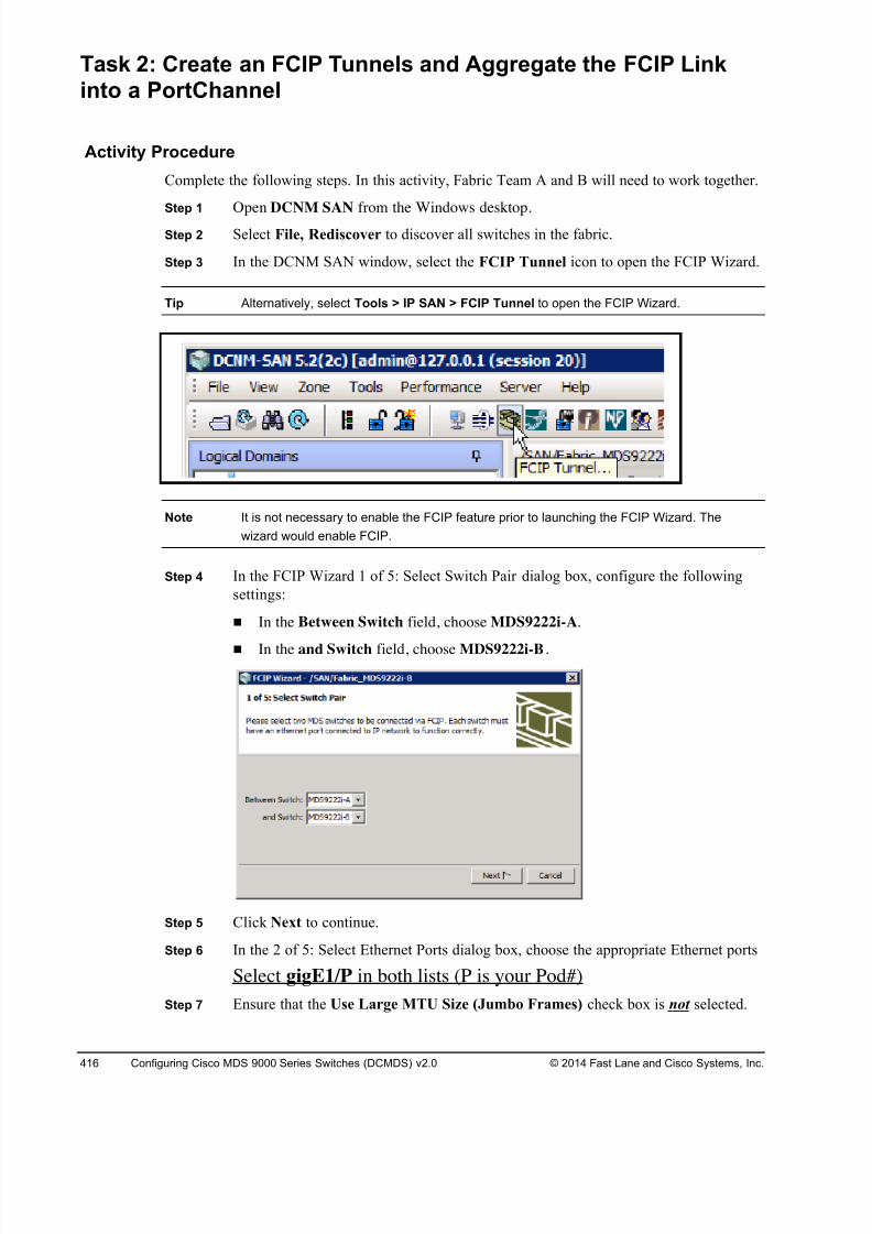
8/18/2019 FL_DCMDS_2.0.3_LG(1).pdf
http://slidepdf.com/reader/full/fldcmds203lg1pdf 416/482
416 Configuring Cisco MDS 9000 Series Switches (DCMDS) v2.0 © 2014 Fast Lane and Cisco Systems, Inc.
Task 2: Create an FCIP Tunnels and Aggregate the FCIP Linkinto a PortChannel
Activity Procedure
Complete the following steps. In this activity, Fabric Team A and B will need to work together.
Step 1 Open DCNM SAN from the Windows desktop.
Step 2 Select File, Rediscover to discover all switches in the fabric.
Step 3 In the DCNM SAN window, select the FCIP Tunnel icon to open the FCIP Wizard.
Tip Alternatively, select Tools > IP SAN > FCIP Tunnel to open the FCIP Wizard.
Note It is not necessary to enable the FCIP feature prior to launching the FCIP Wizard. The
wizard would enable FCIP.
Step 4 In the FCIP Wizard 1 of 5: Select Switch Pair dialog box, configure the following
settings:
! In the Between Switch field, choose MDS9222i-A.
! In the and Switch field, choose MDS9222i-B.
Step 5 Click Next to continue.
Step 6 In the 2 of 5: Select Ethernet Ports dialog box, choose the appropriate Ethernet ports
Select gigE1/P in both lists (P is your Pod#)
Step 7 Ensure that the Use Large MTU Size (Jumbo Frames) check box is not selected.
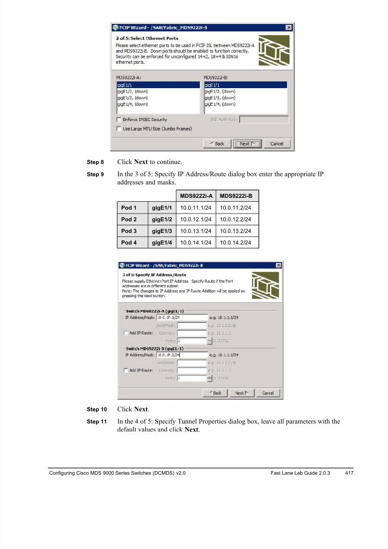
8/18/2019 FL_DCMDS_2.0.3_LG(1).pdf
http://slidepdf.com/reader/full/fldcmds203lg1pdf 417/482
Configuring Cisco MDS 9000 Series Switches (DCMDS) v2.0 Fast Lane Lab Guide 2.0.3 417
Step 8 Click Next to continue.
Step 9 In the 3 of 5: Specify IP Address/Route dialog box enter the appropriate IP
addresses and masks.
MDS9222i-A MDS9222i-B
Pod 1 gigE1/1 10.0.11.1/24 10.0.11.2/24
Pod 2 gigE1/2 10.0.12.1/24 10.0.12.2/24
Pod 3 gigE1/3 10.0.13.1/24 10.0.13.2/24
Pod 4 gigE1/4 10.0.14.1/24 10.0.14.2/24
Step 10 Click Next.
Step 11 In the 4 of 5: Specify Tunnel Properties dialog box, leave all parameters with the
default values and click Next.
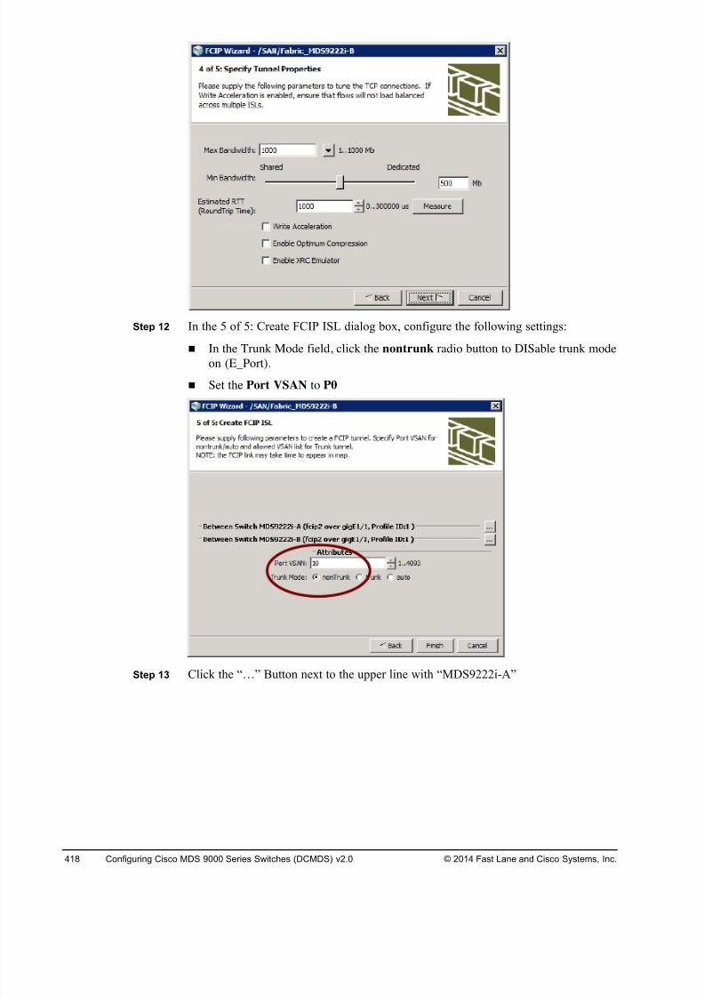
8/18/2019 FL_DCMDS_2.0.3_LG(1).pdf
http://slidepdf.com/reader/full/fldcmds203lg1pdf 418/482
418 Configuring Cisco MDS 9000 Series Switches (DCMDS) v2.0 © 2014 Fast Lane and Cisco Systems, Inc.
Step 12 In the 5 of 5: Create FCIP ISL dialog box, configure the following settings:
! In the Trunk Mode field, click the nontrunk radio button to DISable trunk modeon (E_Port).
! Set the Port VSAN to P0
Step 13 Click the “…” Button next to the upper line with “MDS9222i-A”
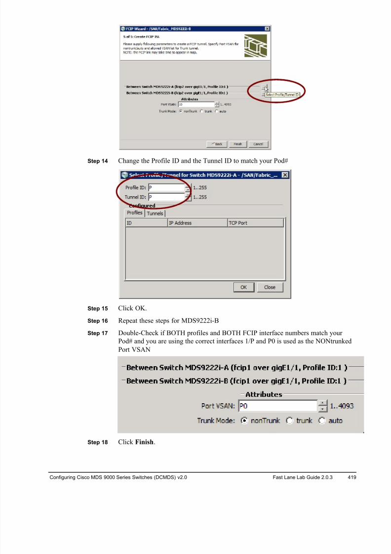
8/18/2019 FL_DCMDS_2.0.3_LG(1).pdf
http://slidepdf.com/reader/full/fldcmds203lg1pdf 419/482
Configuring Cisco MDS 9000 Series Switches (DCMDS) v2.0 Fast Lane Lab Guide 2.0.3 419
Step 14 Change the Profile ID and the Tunnel ID to match your Pod#
Step 15 Click OK.
Step 16 Repeat these steps for MDS9222i-B
Step 17 Double-Check if BOTH profiles and BOTH FCIP interface numbers match your
Pod# and you are using the correct interfaces 1/P and P0 is used as the NONtrunked
Port VSAN
Step 18 Click Finish.
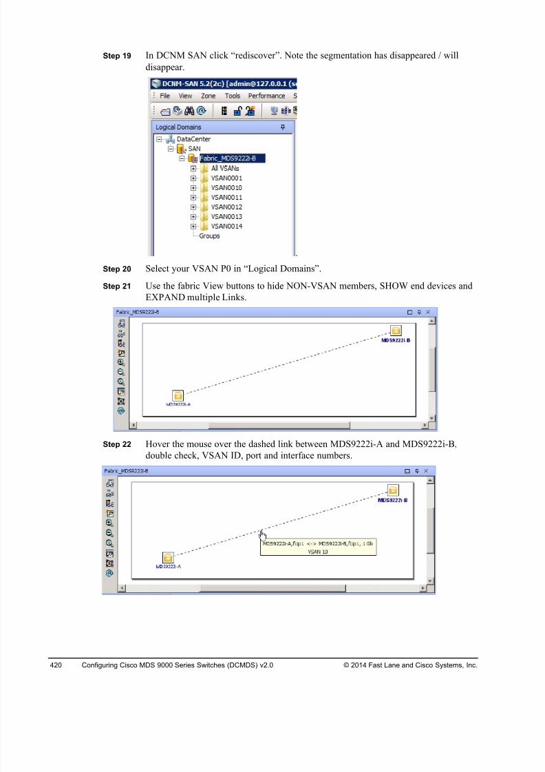
8/18/2019 FL_DCMDS_2.0.3_LG(1).pdf
http://slidepdf.com/reader/full/fldcmds203lg1pdf 420/482
420 Configuring Cisco MDS 9000 Series Switches (DCMDS) v2.0 © 2014 Fast Lane and Cisco Systems, Inc.
Step 19 In DCNM SAN click “rediscover”. Note the segmentation has disappeared / will
disappear.
Step 20 Select your VSAN P0 in “Logical Domains”.
Step 21 Use the fabric View buttons to hide NON-VSAN members, SHOW end devices and
EXPAND multiple Links.
Step 22 Hover the mouse over the dashed link between MDS9222i-A and MDS9222i-B,
double check, VSAN ID, port and interface numbers.
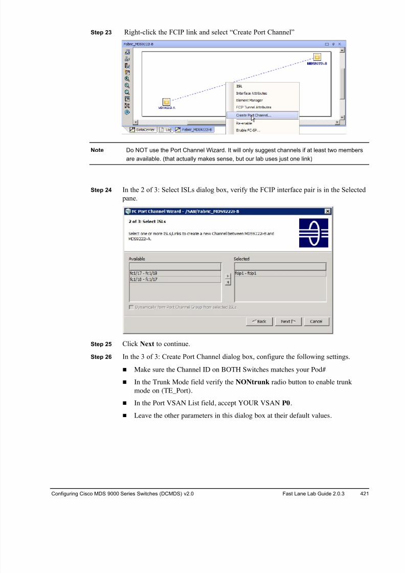
8/18/2019 FL_DCMDS_2.0.3_LG(1).pdf
http://slidepdf.com/reader/full/fldcmds203lg1pdf 421/482
Configuring Cisco MDS 9000 Series Switches (DCMDS) v2.0 Fast Lane Lab Guide 2.0.3 421
Step 23 Right-click the FCIP link and select “Create Port Channel”
Note Do NOT use the Port Channel Wizard. It will only suggest channels if at least two members
are available. (that actually makes sense, but our lab uses just one link)
Step 24 In the 2 of 3: Select ISLs dialog box, verify the FCIP interface pair is in the Selected
pane.
Step 25 Click Next to continue.
Step 26 In the 3 of 3: Create Port Channel dialog box, configure the following settings.
! Make sure the Channel ID on BOTH Switches matches your Pod#
! In the Trunk Mode field verify the NONtrunk radio button to enable trunk
mode on (TE_Port).
! In the Port VSAN List field, accept YOUR VSAN P0.
! Leave the other parameters in this dialog box at their default values.
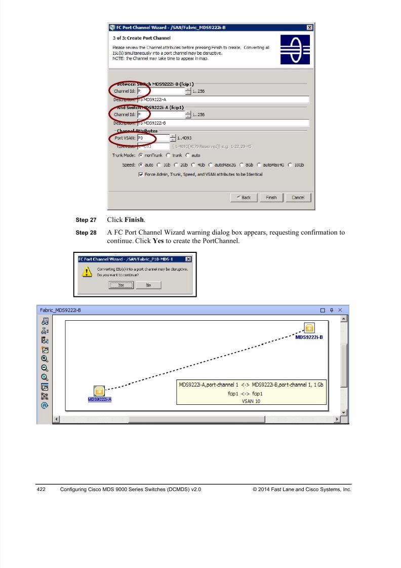
8/18/2019 FL_DCMDS_2.0.3_LG(1).pdf
http://slidepdf.com/reader/full/fldcmds203lg1pdf 422/482
422 Configuring Cisco MDS 9000 Series Switches (DCMDS) v2.0 © 2014 Fast Lane and Cisco Systems, Inc.
Step 27 Click Finish.
Step 28 A FC Port Channel Wizard warning dialog box appears, requesting confirmation to
continue. Click Yes to create the PortChannel.
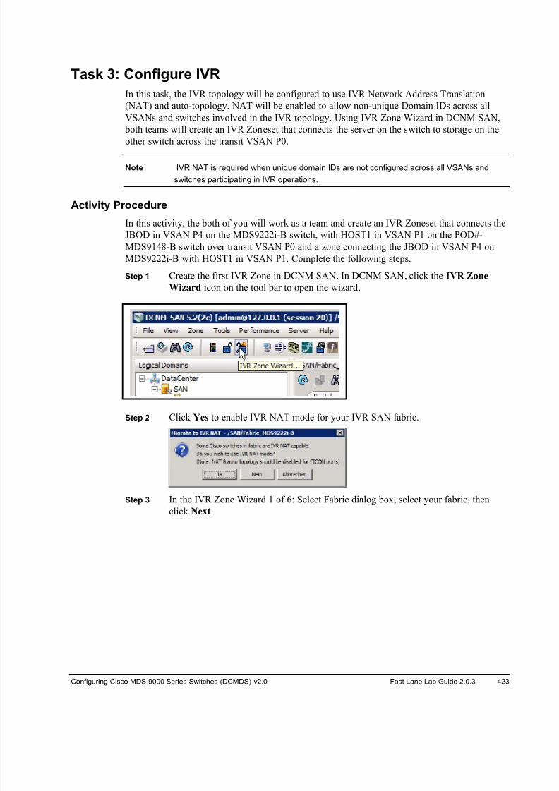
8/18/2019 FL_DCMDS_2.0.3_LG(1).pdf
http://slidepdf.com/reader/full/fldcmds203lg1pdf 423/482
Configuring Cisco MDS 9000 Series Switches (DCMDS) v2.0 Fast Lane Lab Guide 2.0.3 423
Task 3: Configure IVR
In this task, the IVR topology will be configured to use IVR Network Address Translation
(NAT) and auto-topology. NAT will be enabled to allow non-unique Domain IDs across all
VSANs and switches involved in the IVR topology. Using IVR Zone Wizard in DCNM SAN,
both teams will create an IVR Zoneset that connects the server on the switch to storage on the
other switch across the transit VSAN P0.
Note IVR NAT is required when unique domain IDs are not configured across all VSANs and
switches participating in IVR operations.
Activity Procedure
In this activity, the both of you will work as a team and create an IVR Zoneset that connects the
JBOD in VSAN P4 on the MDS9222i-B switch, with HOST1 in VSAN P1 on the POD#-
MDS9148-B switch over transit VSAN P0 and a zone connecting the JBOD in VSAN P4 on
MDS9222i-B with HOST1 in VSAN P1. Complete the following steps.
Step 1 Create the first IVR Zone in DCNM SAN. In DCNM SAN, click the IVR ZoneWizard icon on the tool bar to open the wizard.
Step 2 Click Yes to enable IVR NAT mode for your IVR SAN fabric.
Step 3 In the IVR Zone Wizard 1 of 6: Select Fabric dialog box, select your fabric, then
click Next.
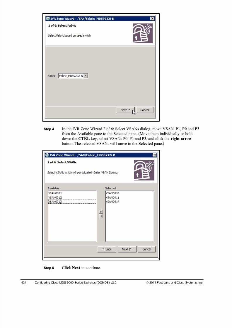
8/18/2019 FL_DCMDS_2.0.3_LG(1).pdf
http://slidepdf.com/reader/full/fldcmds203lg1pdf 424/482
424 Configuring Cisco MDS 9000 Series Switches (DCMDS) v2.0 © 2014 Fast Lane and Cisco Systems, Inc.
Step 4 In the IVR Zone Wizard 2 of 6: Select VSANs dialog, move VSAN P1, P0 and P3
from the Available pane to the Selected pane. (Move them individually or hold
down the CTRL key, select VSANs P0, P1 and P3, and click the right-arrow
button. The selected VSANs will move to the Selected pane.)
Step 5 Click Next to continue.
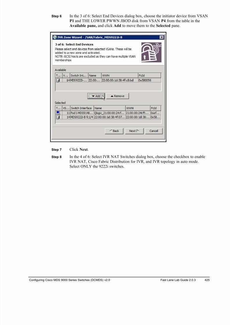
8/18/2019 FL_DCMDS_2.0.3_LG(1).pdf
http://slidepdf.com/reader/full/fldcmds203lg1pdf 425/482
Configuring Cisco MDS 9000 Series Switches (DCMDS) v2.0 Fast Lane Lab Guide 2.0.3 425
Step 6 In the 3 of 6: Select End Devices dialog box, choose the initiator device from VSAN
P1 and THE LOWER PWWN JBOD disk from VSAN P4 from the table in the
Available pane, and click Add to move them to the Selected pane.
Step 7 Click Next.
Step 8 In the 4 of 6: Select IVR NAT Switches dialog box, choose the checkbox to enable
IVR NAT, Cisco Fabric Distribution for IVR, and IVR topology in auto mode.
Select ONLY the 9222i switches.
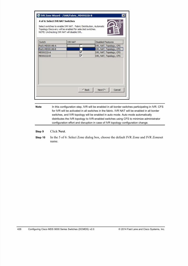
8/18/2019 FL_DCMDS_2.0.3_LG(1).pdf
http://slidepdf.com/reader/full/fldcmds203lg1pdf 426/482
426 Configuring Cisco MDS 9000 Series Switches (DCMDS) v2.0 © 2014 Fast Lane and Cisco Systems, Inc.
Note In this configuration step, IVR will be enabled in all border switches participating in IVR. CFS
for IVR will be activated in all switches in the fabric. IVR NAT will be enabled in all border
switches, and IVR topology will be enabled in auto mode. Auto mode automatically
distributes the IVR topology to IVR-enabled switches using CFS to minimize administrator
configuration effort and disruption in case of IVR topology configuration change.
Step 9 Click Next.
Step 10 In the 5 of 6: Select Zone dialog box, choose the default IVR Zone and IVR Zoneset
name.
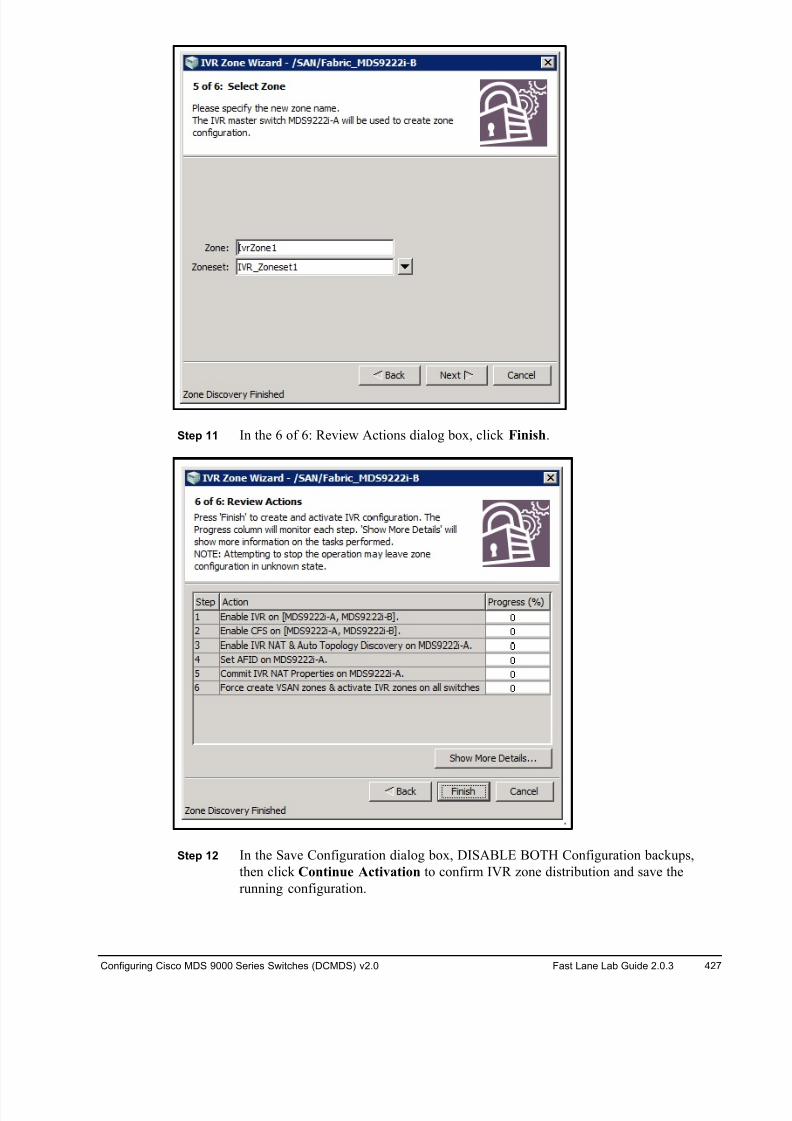
8/18/2019 FL_DCMDS_2.0.3_LG(1).pdf
http://slidepdf.com/reader/full/fldcmds203lg1pdf 427/482
Configuring Cisco MDS 9000 Series Switches (DCMDS) v2.0 Fast Lane Lab Guide 2.0.3 427
Step 11 In the 6 of 6: Review Actions dialog box, click Finish.
Step 12 In the Save Configuration dialog box, DISABLE BOTH Configuration backups,
then click Continue Activation to confirm IVR zone distribution and save the
running configuration.
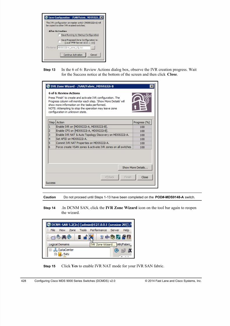
8/18/2019 FL_DCMDS_2.0.3_LG(1).pdf
http://slidepdf.com/reader/full/fldcmds203lg1pdf 428/482
428 Configuring Cisco MDS 9000 Series Switches (DCMDS) v2.0 © 2014 Fast Lane and Cisco Systems, Inc.
Step 13 In the 6 of 6: Review Actions dialog box, observe the IVR creation progress. Wait
for the Success notice at the bottom of the screen and then click Close.
Caution Do not proceed until Steps 1-13 have been completed on the POD#-MDS9148-A switch.
Step 14 .In DCNM SAN, click the IVR Zone Wizard icon on the tool bar again to reopen
the wizard.
Step 15 Click Yes to enable IVR NAT mode for your IVR SAN fabric.
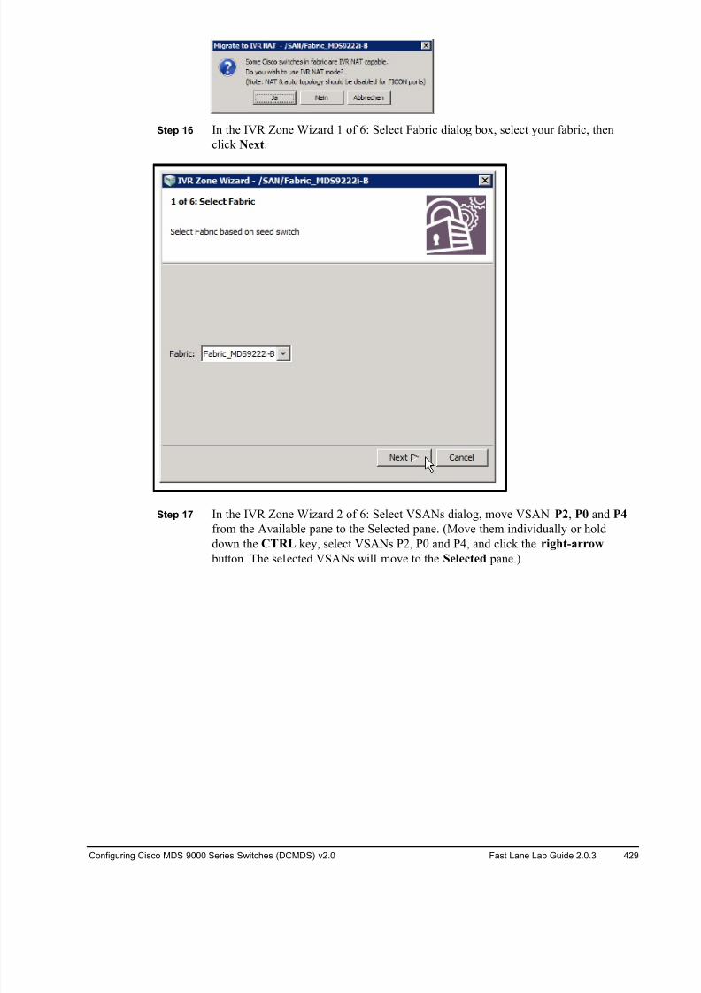
8/18/2019 FL_DCMDS_2.0.3_LG(1).pdf
http://slidepdf.com/reader/full/fldcmds203lg1pdf 429/482
Configuring Cisco MDS 9000 Series Switches (DCMDS) v2.0 Fast Lane Lab Guide 2.0.3 429
Step 16 In the IVR Zone Wizard 1 of 6: Select Fabric dialog box, select your fabric, then
click Next.
Step 17 In the IVR Zone Wizard 2 of 6: Select VSANs dialog, move VSAN P2, P0 and P4
from the Available pane to the Selected pane. (Move them individually or hold
down the CTRL key, select VSANs P2, P0 and P4, and click the right-arrow
button. The selected VSANs will move to the Selected pane.)
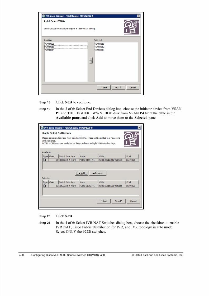
8/18/2019 FL_DCMDS_2.0.3_LG(1).pdf
http://slidepdf.com/reader/full/fldcmds203lg1pdf 430/482
430 Configuring Cisco MDS 9000 Series Switches (DCMDS) v2.0 © 2014 Fast Lane and Cisco Systems, Inc.
Step 18 Click Next to continue.Step 19 In the 3 of 6: Select End Devices dialog box, choose the initiator device from VSAN
P1 and THE HIGHER PWWN JBOD disk from VSAN P4 from the table in the
Available pane, and click Add to move them to the Selected pane.
Step 20 Click Next.
Step 21 In the 4 of 6: Select IVR NAT Switches dialog box, choose the checkbox to enable
IVR NAT, Cisco Fabric Distribution for IVR, and IVR topology in auto mode.
Select ONLY the 9222i switches.
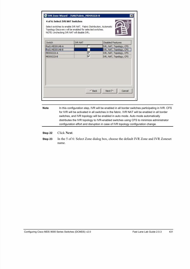
8/18/2019 FL_DCMDS_2.0.3_LG(1).pdf
http://slidepdf.com/reader/full/fldcmds203lg1pdf 431/482
Configuring Cisco MDS 9000 Series Switches (DCMDS) v2.0 Fast Lane Lab Guide 2.0.3 431
Note In this configuration step, IVR will be enabled in all border switches participating in IVR. CFS
for IVR will be activated in all switches in the fabric. IVR NAT will be enabled in all border
switches, and IVR topology will be enabled in auto mode. Auto mode automatically
distributes the IVR topology to IVR-enabled switches using CFS to minimize administrator
configuration effort and disruption in case of IVR topology configuration change.
Step 22 Click Next.
Step 23 In the 5 of 6: Select Zone dialog box, choose the default IVR Zone and IVR Zoneset
name.
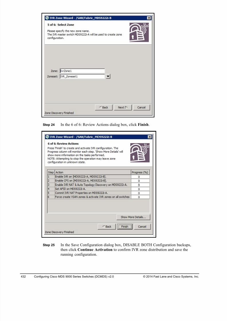
8/18/2019 FL_DCMDS_2.0.3_LG(1).pdf
http://slidepdf.com/reader/full/fldcmds203lg1pdf 432/482
432 Configuring Cisco MDS 9000 Series Switches (DCMDS) v2.0 © 2014 Fast Lane and Cisco Systems, Inc.
Step 24 In the 6 of 6: Review Actions dialog box, click Finish.
Step 25 In the Save Configuration dialog box, DISABLE BOTH Configuration backups,
then click Continue Activation to confirm IVR zone distribution and save the
running configuration.
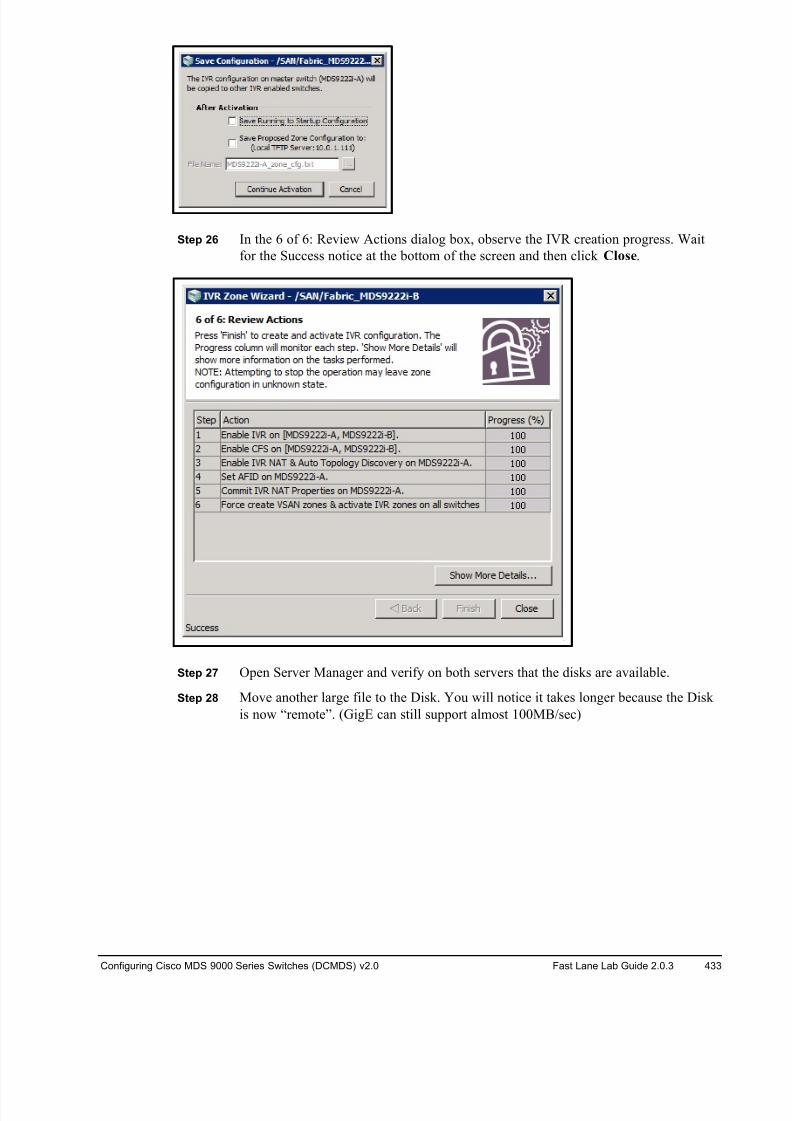
8/18/2019 FL_DCMDS_2.0.3_LG(1).pdf
http://slidepdf.com/reader/full/fldcmds203lg1pdf 433/482
Configuring Cisco MDS 9000 Series Switches (DCMDS) v2.0 Fast Lane Lab Guide 2.0.3 433
Step 26 In the 6 of 6: Review Actions dialog box, observe the IVR creation progress. Wait
for the Success notice at the bottom of the screen and then click Close.
Step 27 Open Server Manager and verify on both servers that the disks are available.
Step 28 Move another large file to the Disk. You will notice it takes longer because the Disk
is now “remote”. (GigE can still support almost 100MB/sec)
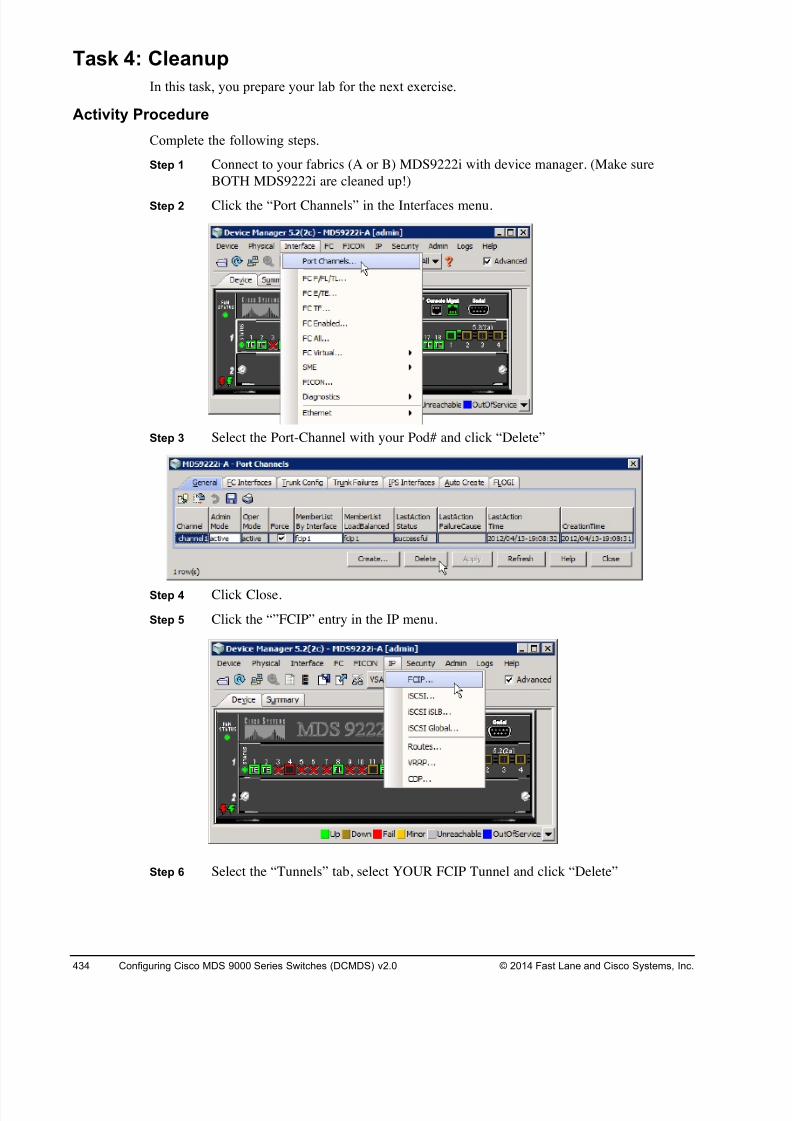
8/18/2019 FL_DCMDS_2.0.3_LG(1).pdf
http://slidepdf.com/reader/full/fldcmds203lg1pdf 434/482
434 Configuring Cisco MDS 9000 Series Switches (DCMDS) v2.0 © 2014 Fast Lane and Cisco Systems, Inc.
Task 4: Cleanup
In this task, you prepare your lab for the next exercise.
Activity Procedure
Complete the following steps.
Step 1 Connect to your fabrics (A or B) MDS9222i with device manager. (Make sure
BOTH MDS9222i are cleaned up!)
Step 2 Click the “Port Channels” in the Interfaces menu.
Step 3 Select the Port-Channel with your Pod# and click “Delete”
Step 4 Click Close.
Step 5 Click the “”FCIP” entry in the IP menu.
Step 6 Select the “Tunnels” tab, select YOUR FCIP Tunnel and click “Delete”
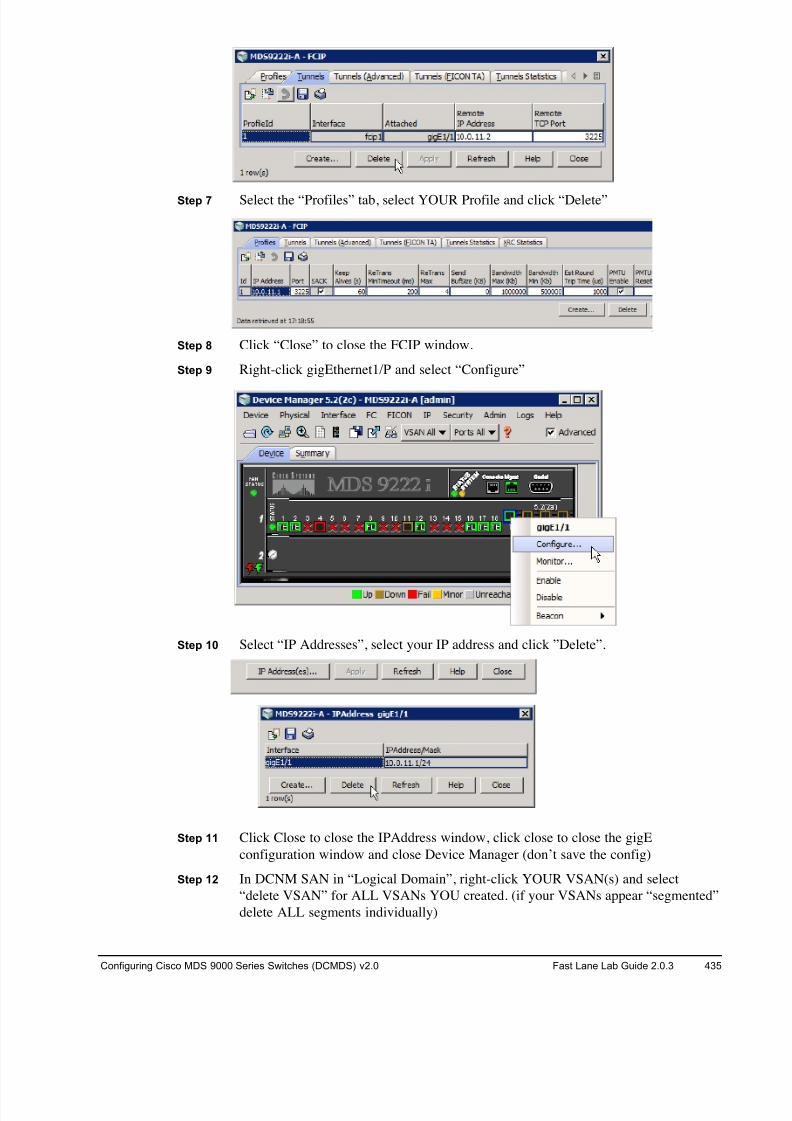
8/18/2019 FL_DCMDS_2.0.3_LG(1).pdf
http://slidepdf.com/reader/full/fldcmds203lg1pdf 435/482
Configuring Cisco MDS 9000 Series Switches (DCMDS) v2.0 Fast Lane Lab Guide 2.0.3 435
Step 7 Select the “Profiles” tab, select YOUR Profile and click “Delete”
Step 8 Click “Close” to close the FCIP window.
Step 9 Right-click gigEthernet1/P and select “Configure”
Step 10 Select “IP Addresses”, select your IP address and click ”Delete”.
Step 11 Click Close to close the IPAddress window, click close to close the gigE
configuration window and close Device Manager (don’t save the config)
Step 12 In DCNM SAN in “Logical Domain”, right-click YOUR VSAN(s) and select
“delete VSAN” for ALL VSANs YOU created. (if your VSANs appear “segmented”
delete ALL segments individually)
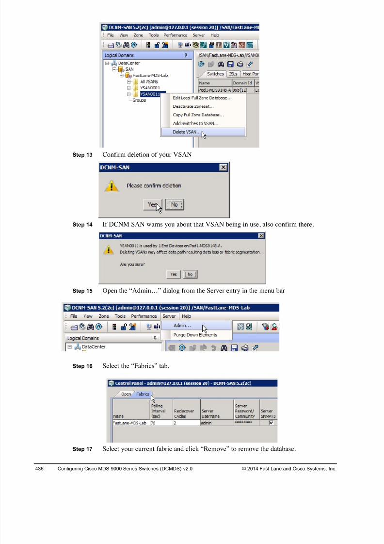
8/18/2019 FL_DCMDS_2.0.3_LG(1).pdf
http://slidepdf.com/reader/full/fldcmds203lg1pdf 436/482
436 Configuring Cisco MDS 9000 Series Switches (DCMDS) v2.0 © 2014 Fast Lane and Cisco Systems, Inc.
Step 13 Confirm deletion of your VSAN
Step 14 If DCNM SAN warns you about that VSAN being in use, also confirm there.
Step 15 Open the “Admin…” dialog from the Server entry in the menu bar
Step 16 Select the “Fabrics” tab.
Step 17 Select your current fabric and click “Remove” to remove the database.
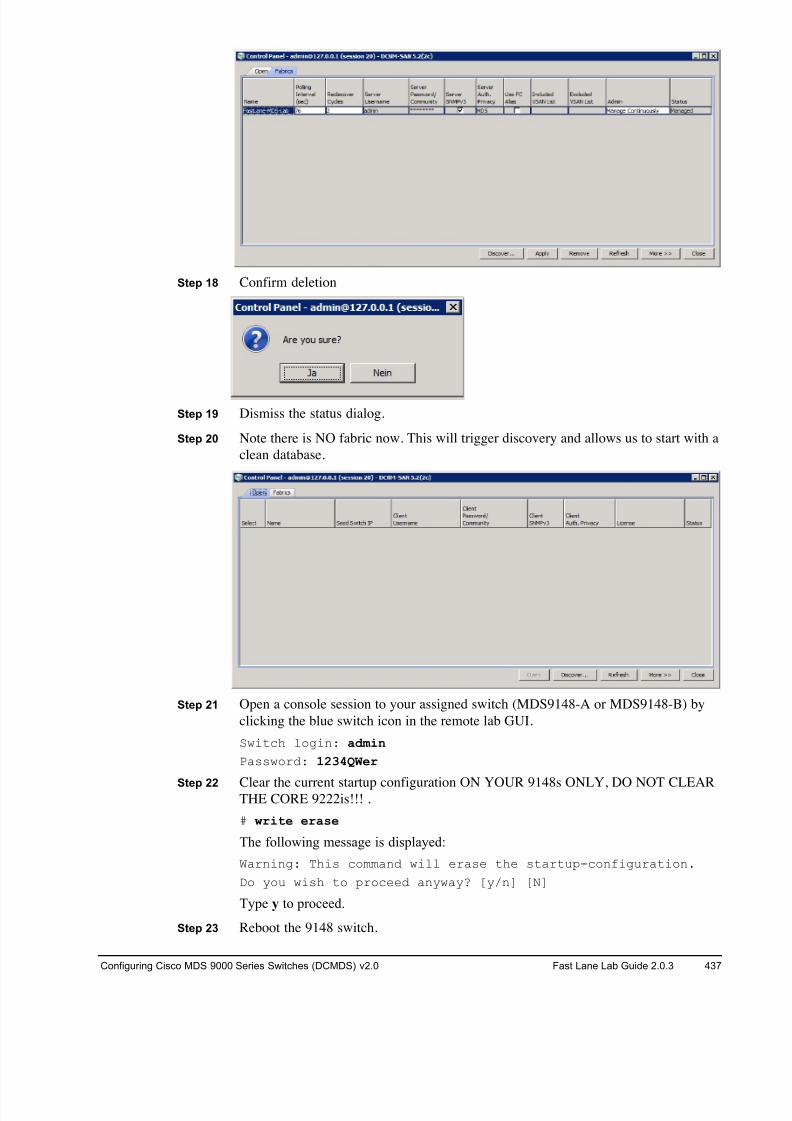
8/18/2019 FL_DCMDS_2.0.3_LG(1).pdf
http://slidepdf.com/reader/full/fldcmds203lg1pdf 437/482
Configuring Cisco MDS 9000 Series Switches (DCMDS) v2.0 Fast Lane Lab Guide 2.0.3 437
Step 18 Confirm deletion
Step 19 Dismiss the status dialog.
Step 20 Note there is NO fabric now. This will trigger discovery and allows us to start with a
clean database.
Step 21 Open a console session to your assigned switch (MDS9148-A or MDS9148-B) by
clicking the blue switch icon in the remote lab GUI.
Switch login: admin
Password: 1234QWer
Step 22 Clear the current startup configuration ON YOUR 9148s ONLY, DO NOT CLEARTHE CORE 9222is!!! .
# write erase
The following message is displayed:
Warning: This command will erase the startup-configuration.
Do you wish to proceed anyway? [y/n] [N]
Type y to proceed.
Step 23 Reboot the 9148 switch.

8/18/2019 FL_DCMDS_2.0.3_LG(1).pdf
http://slidepdf.com/reader/full/fldcmds203lg1pdf 438/482
438 Configuring Cisco MDS 9000 Series Switches (DCMDS) v2.0 © 2014 Fast Lane and Cisco Systems, Inc.
# reload
This command will reboot the system. (y/n)?
Type y to proceed.
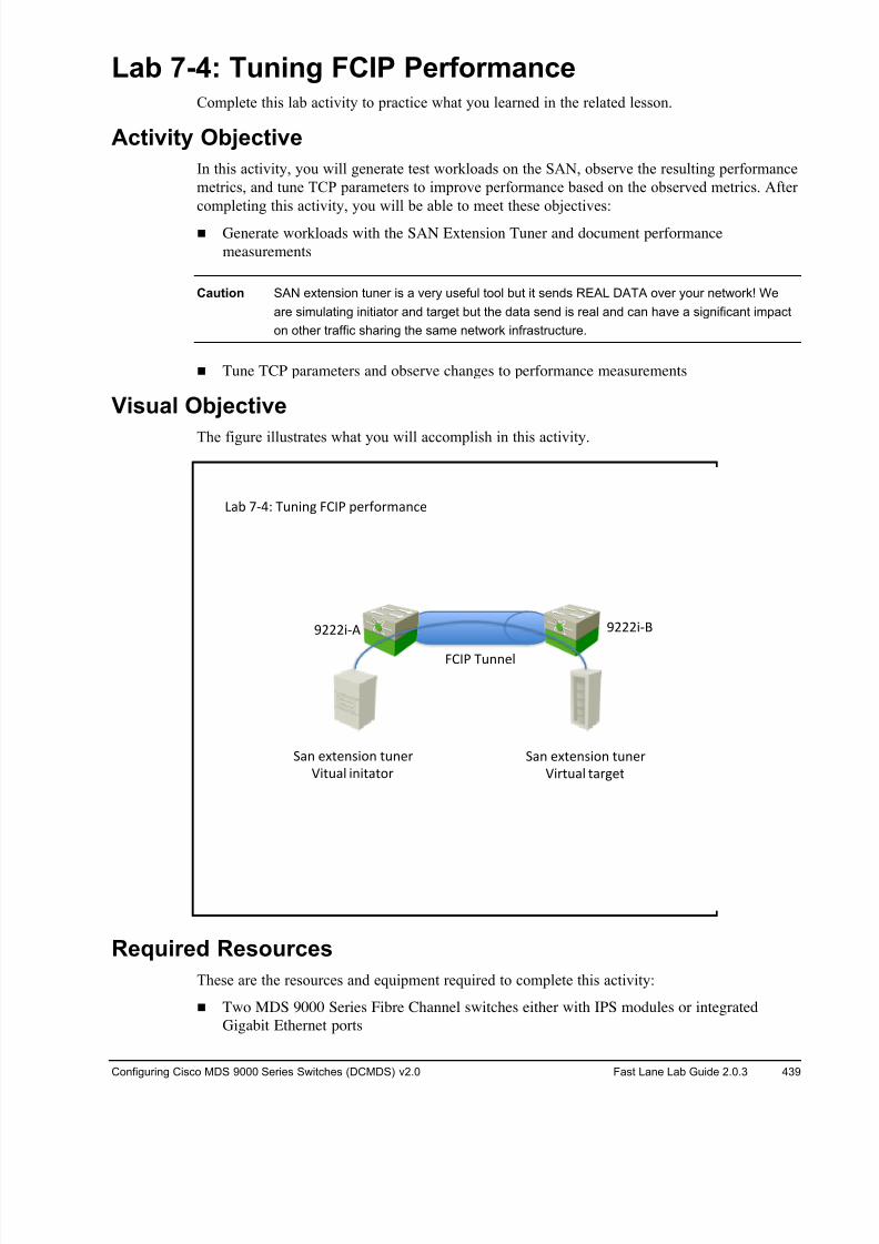
8/18/2019 FL_DCMDS_2.0.3_LG(1).pdf
http://slidepdf.com/reader/full/fldcmds203lg1pdf 439/482
Configuring Cisco MDS 9000 Series Switches (DCMDS) v2.0 Fast Lane Lab Guide 2.0.3 439
Lab 7-4: Tuning FCIP Performance Complete this lab activity to practice what you learned in the related lesson.
Activity Objective
In this activity, you will generate test workloads on the SAN, observe the resulting performance
metrics, and tune TCP parameters to improve performance based on the observed metrics. After
completing this activity, you will be able to meet these objectives:
! Generate workloads with the SAN Extension Tuner and document performance
measurements
Caution SAN extension tuner is a very useful tool but it sends REAL DATA over your network! We
are simulating initiator and target but the data send is real and can have a significant impact
on other traffic sharing the same network infrastructure.
! Tune TCP parameters and observe changes to performance measurements
Visual Objective
The figure illustrates what you will accomplish in this activity.
Required Resources
These are the resources and equipment required to complete this activity:
! Two MDS 9000 Series Fibre Channel switches either with IPS modules or integrated
Gigabit Ethernet ports
!"""#$% !"""#$'
()* +$,- ./0#01 2345 6789:8;)0<7
2345 ./007=
>)0 7?@70A#:0 @/078
B#@/)= #0#@)@:8
>)0 7?@70A#:0 @/078
B#8@/)= @)817@
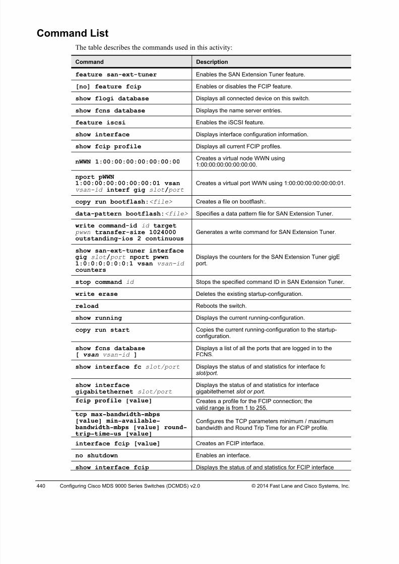
8/18/2019 FL_DCMDS_2.0.3_LG(1).pdf
http://slidepdf.com/reader/full/fldcmds203lg1pdf 440/482
440 Configuring Cisco MDS 9000 Series Switches (DCMDS) v2.0 © 2014 Fast Lane and Cisco Systems, Inc.
Command List
The table describes the commands used in this activity:
Command Description
feature san-ext-tuner Enables the SAN Extension Tuner feature.
[no] feature fcip Enables or disables the FCIP feature.
show flogi database Displays all connected device on this switch.
show fcns database Displays the name server entries.
feature iscsi Enables the iSCSI feature.
show interface Displays interface configuration information.
show fcip profile Displays all current FCIP profiles.
nWWN 1:00:00:00:00:00:00:00Creates a virtual node WWN using1:00:00:00:00:00:00:00.
nport pWWN1:00:00:00:00:00:00:01 vsanvsan-id interf gig slot/ port
Creates a virtual port WWN using 1:00:00:00:00:00:00:01.
copy run bootflash:<file> Creates a file on bootflash:.
data-pattern bootflash:<file> Specifies a data pattern file for SAN Extension Tuner.
write command-id id target pwwn transfer-size 1024000outstanding-ios 2 continuous
Generates a write command for SAN Extension Tuner.
show san-ext-tuner interfacegig slot/ port nport pwwn1:0:0:0:0:0:0:1 vsan vsan-id counters
Displays the counters for the SAN Extension Tuner gigEport.
stop command id Stops the specified command ID in SAN Extension Tuner.
write erase Deletes the existing startup-configuration.
reload Reboots the switch.
show running Displays the current running-configuration.
copy run start Copies the current running-configuration to the startup-configuration.
show fcns database[ vsan vsan-id ]
Displays a list of all the ports that are logged in to theFCNS.
show interface fc slot/port Displays the status of and statistics for interface fc slot/port.
show interfacegigabitethernet slot/port
Displays the status of and statistics for interfacegigabitethernet slot or port.
fcip profile [value] Creates a profile for the FCIP connection; thevalid range is from 1 to 255.
tcp max-bandwidth-mbps[value] min-available-bandwidth-mbps [value] round-trip-time-us [value]
Configures the TCP parameters minimum / maximumbandwidth and Round Trip Time for an FCIP profile.
interface fcip [value] Creates an FCIP interface.
no shutdown Enables an interface.
show interface fcip Displays the status of and statistics for FCIP interface
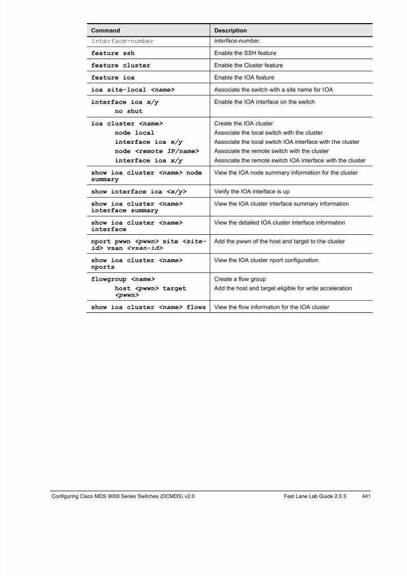
8/18/2019 FL_DCMDS_2.0.3_LG(1).pdf
http://slidepdf.com/reader/full/fldcmds203lg1pdf 441/482
Configuring Cisco MDS 9000 Series Switches (DCMDS) v2.0 Fast Lane Lab Guide 2.0.3 441
Command Description
interface-number interface-number.
feature ssh Enable the SSH feature
feature cluster Enable the Cluster feature
feature ioa Enable the IOA feature
ioa site-local <name> Associate the switch with a site name for IOA
interface ioa x/y no shut
Enable the IOA interface on the switch
ioa cluster <name>
node local
interface ioa x/y
node <remote IP/name>
interface ioa x/y
Create the IOA cluster
Associate the local switch with the cluster
Associate the local switch IOA interface with the cluster
Associate the remote switch with the cluster
Associate the remote switch IOA interface with the cluster
show ioa cluster <name> nodesummary
View the IOA node summary information for the cluster
show interface ioa <x/y> Verify the IOA interface is up
show ioa cluster <name> interface summary
View the IOA cluster interface summary information
show ioa cluster <name> interface
View the detailed IOA cluster interface information
nport pwwn <pwwn> site <site-id> vsan <vsan-id>
Add the pwwn of the host and target to the cluster
show ioa cluster <name> nports
View the IOA cluster nport configuration
flowgroup <name>
host <pwwn> target<pwwn>
Create a flow group
Add the host and target eligible for write acceleration
show ioa cluster <name> flows View the flow information for the IOA cluster
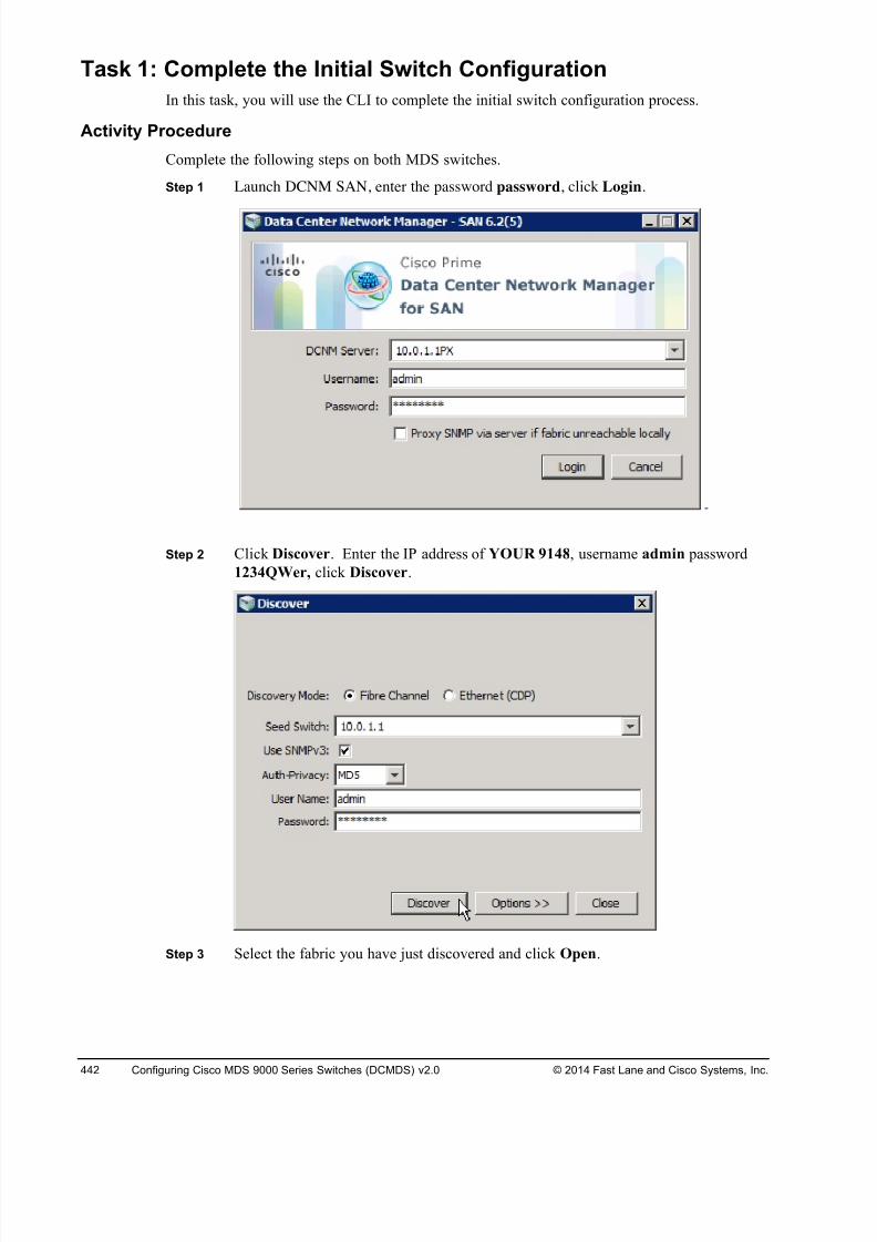
8/18/2019 FL_DCMDS_2.0.3_LG(1).pdf
http://slidepdf.com/reader/full/fldcmds203lg1pdf 442/482
442 Configuring Cisco MDS 9000 Series Switches (DCMDS) v2.0 © 2014 Fast Lane and Cisco Systems, Inc.
Task 1: Complete the Initial Switch Configuration
In this task, you will use the CLI to complete the initial switch configuration process.
Activity Procedure
Complete the following steps on both MDS switches.
Step 1 Launch DCNM SAN, enter the password password, click Login.
Step 2 Click Discover. Enter the IP address of YOUR 9148, username admin password
1234QWer, click Discover.
Step 3 Select the fabric you have just discovered and click Open.
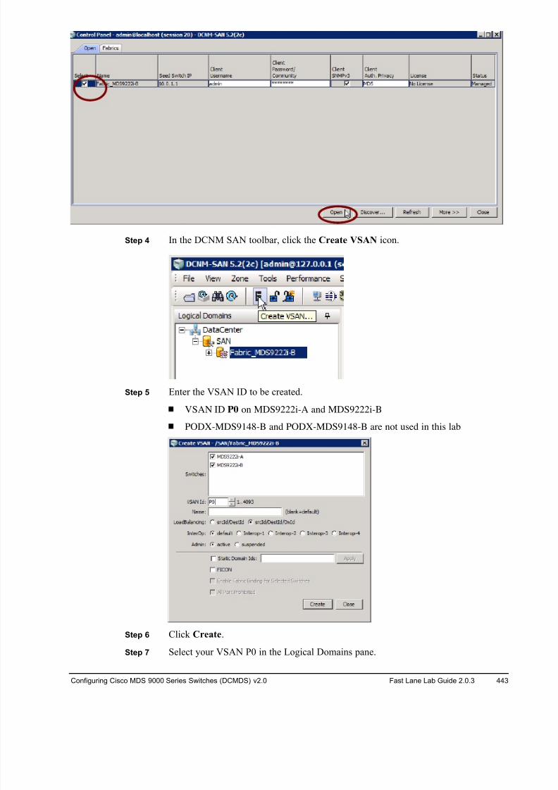
8/18/2019 FL_DCMDS_2.0.3_LG(1).pdf
http://slidepdf.com/reader/full/fldcmds203lg1pdf 443/482
Configuring Cisco MDS 9000 Series Switches (DCMDS) v2.0 Fast Lane Lab Guide 2.0.3 443
Step 4 In the DCNM SAN toolbar, click the Create VSAN icon.
Step 5 Enter the VSAN ID to be created.
VSAN ID P0 on MDS9222i-A and MDS9222i-B
PODX-MDS9148-B and PODX-MDS9148-B are not used in this lab
Step 6 Click Create.
Step 7 Select your VSAN P0 in the Logical Domains pane.
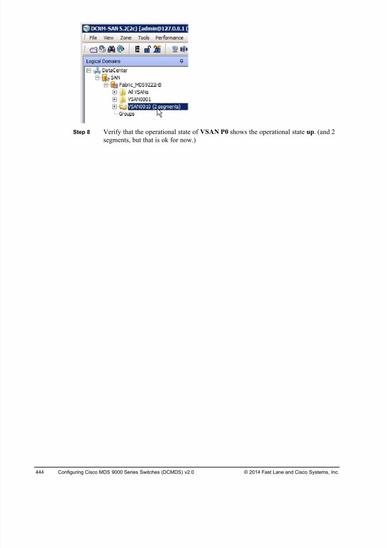
8/18/2019 FL_DCMDS_2.0.3_LG(1).pdf
http://slidepdf.com/reader/full/fldcmds203lg1pdf 444/482
444 Configuring Cisco MDS 9000 Series Switches (DCMDS) v2.0 © 2014 Fast Lane and Cisco Systems, Inc.
Step 8 Verify that the operational state of VSAN P0 shows the operational state up. (and 2
segments, but that is ok for now.)
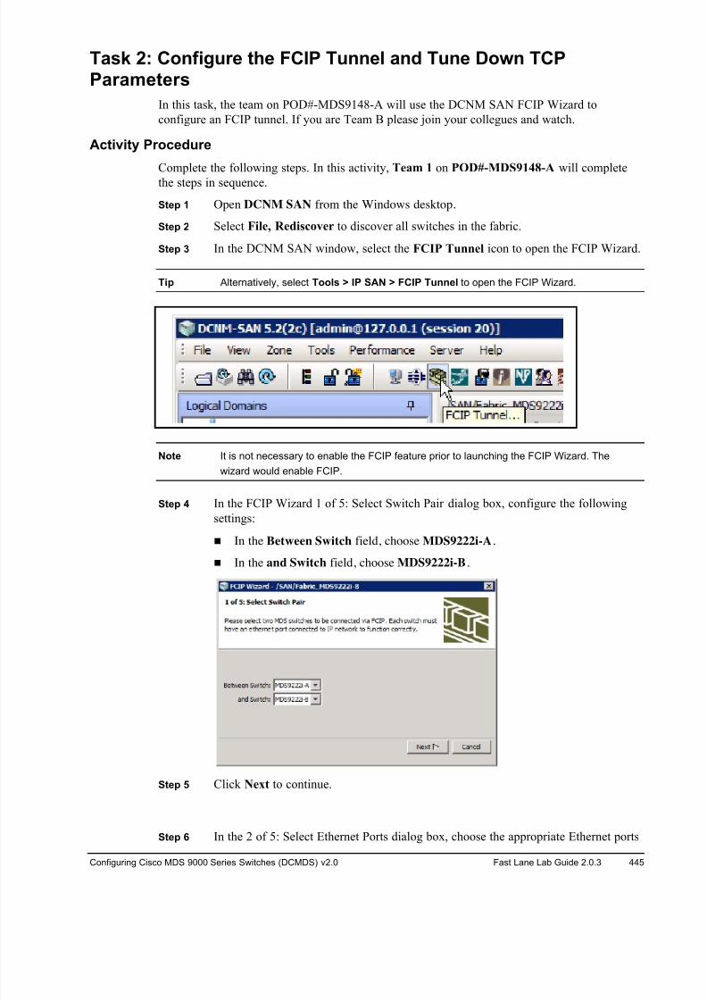
8/18/2019 FL_DCMDS_2.0.3_LG(1).pdf
http://slidepdf.com/reader/full/fldcmds203lg1pdf 445/482
Configuring Cisco MDS 9000 Series Switches (DCMDS) v2.0 Fast Lane Lab Guide 2.0.3 445
Task 2: Conf igure the FCIP Tunnel and Tune Down TCPParameters
In this task, the team on POD#-MDS9148-A will use the DCNM SAN FCIP Wizard to
configure an FCIP tunnel. If you are Team B please join your collegues and watch.
Activity Procedure
Complete the following steps. In this activity, Team 1 on POD#-MDS9148-A will complete
the steps in sequence.
Step 1 Open DCNM SAN from the Windows desktop.
Step 2 Select File, Rediscover to discover all switches in the fabric.
Step 3 In the DCNM SAN window, select the FCIP Tunnel icon to open the FCIP Wizard.
Tip Alternatively, select Tools > IP SAN > FCIP Tunnel to open the FCIP Wizard.
Note It is not necessary to enable the FCIP feature prior to launching the FCIP Wizard. The
wizard would enable FCIP.
Step 4 In the FCIP Wizard 1 of 5: Select Switch Pair dialog box, configure the following
settings:
! In the Between Switch field, choose MDS9222i-A.
! In the and Switch field, choose MDS9222i-B.
Step 5 Click Next to continue.
Step 6 In the 2 of 5: Select Ethernet Ports dialog box, choose the appropriate Ethernet ports
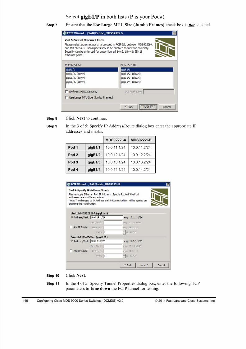
8/18/2019 FL_DCMDS_2.0.3_LG(1).pdf
http://slidepdf.com/reader/full/fldcmds203lg1pdf 446/482
446 Configuring Cisco MDS 9000 Series Switches (DCMDS) v2.0 © 2014 Fast Lane and Cisco Systems, Inc.
Select gigE1/P in both lists (P is your Pod#)
Step 7 Ensure that the Use Large MTU Size (Jumbo Frames) check box is not selected.
Step 8 Click Next to continue.
Step 9 In the 3 of 5: Specify IP Address/Route dialog box enter the appropriate IP
addresses and masks.
MDS9222i-A MDS9222i-B
Pod 1 gigE1/1 10.0.11.1/24 10.0.11.2/24
Pod 2 gigE1/2 10.0.12.1/24 10.0.12.2/24
Pod 3 gigE1/3 10.0.13.1/24 10.0.13.2/24
Pod 4 gigE1/4 10.0.14.1/24 10.0.14.2/24
Step 10 Click Next.
Step 11 In the 4 of 5: Specify Tunnel Properties dialog box, enter the following TCP
parameters to tune down the FCIP tunnel for testing:
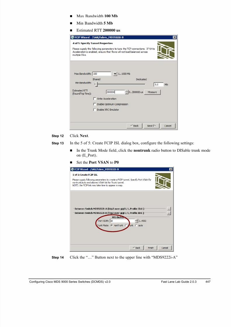
8/18/2019 FL_DCMDS_2.0.3_LG(1).pdf
http://slidepdf.com/reader/full/fldcmds203lg1pdf 447/482
Configuring Cisco MDS 9000 Series Switches (DCMDS) v2.0 Fast Lane Lab Guide 2.0.3 447
! Max Bandwidth 100 Mb
! Min Bandwidth 5 Mb
! Estimated RTT 200000 us
Step 12 Click Next.
Step 13 In the 5 of 5: Create FCIP ISL dialog box, configure the following settings:
! In the Trunk Mode field, click the nontrunk radio button to DISable trunk mode
on (E_Port).
! Set the Port VSAN to P0
Step 14 Click the “…” Button next to the upper line with “MDS9222i-A”
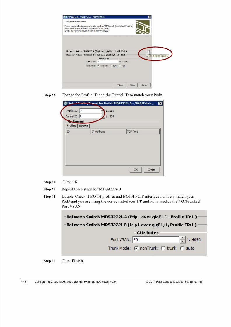
8/18/2019 FL_DCMDS_2.0.3_LG(1).pdf
http://slidepdf.com/reader/full/fldcmds203lg1pdf 448/482
448 Configuring Cisco MDS 9000 Series Switches (DCMDS) v2.0 © 2014 Fast Lane and Cisco Systems, Inc.
Step 15 Change the Profile ID and the Tunnel ID to match your Pod#
Step 16 Click OK.
Step 17 Repeat these steps for MDS9222i-B
Step 18 Double-Check if BOTH profiles and BOTH FCIP interface numbers match your
Pod# and you are using the correct interfaces 1/P and P0 is used as the NONtrunked
Port VSAN
Step 19 Click Finish.
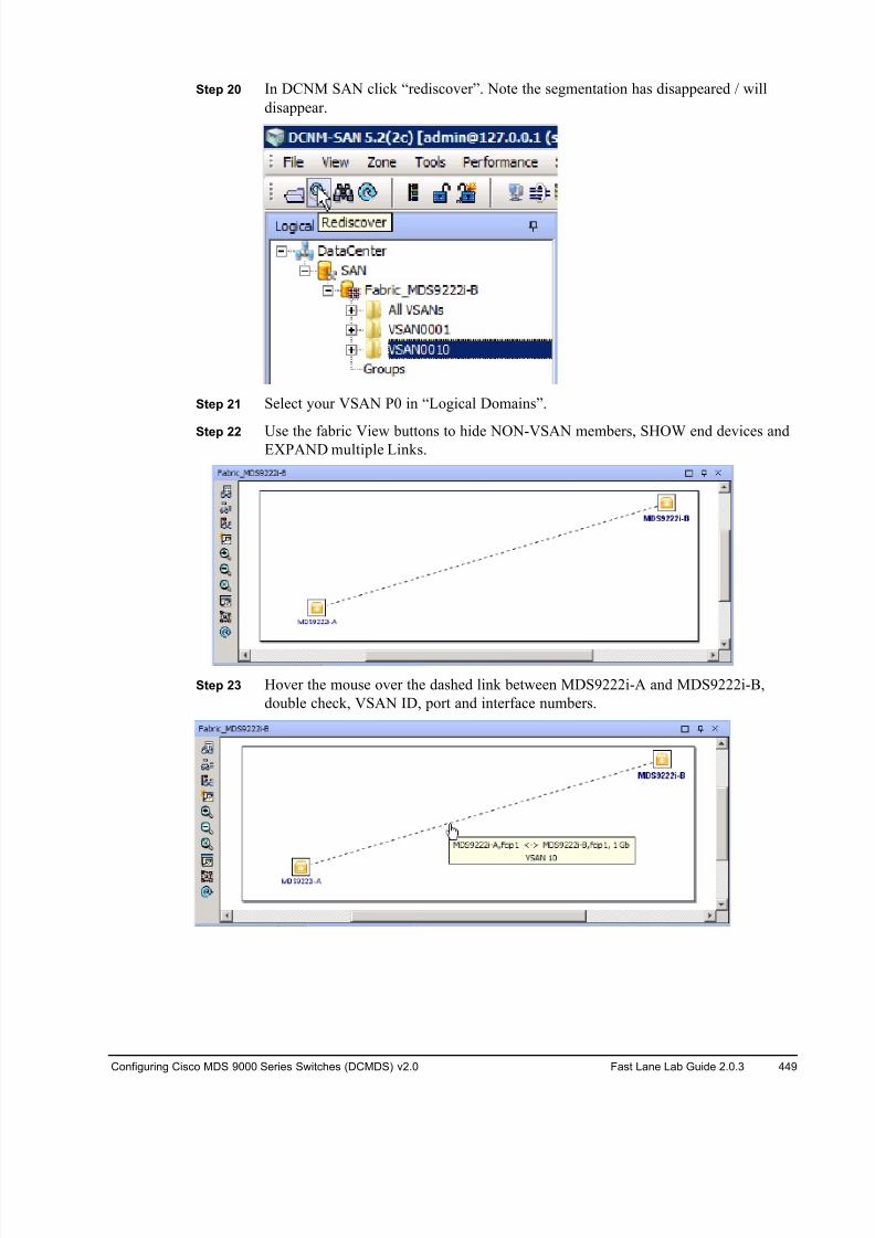
8/18/2019 FL_DCMDS_2.0.3_LG(1).pdf
http://slidepdf.com/reader/full/fldcmds203lg1pdf 449/482
Configuring Cisco MDS 9000 Series Switches (DCMDS) v2.0 Fast Lane Lab Guide 2.0.3 449
Step 20 In DCNM SAN click “rediscover”. Note the segmentation has disappeared / will
disappear.
Step 21 Select your VSAN P0 in “Logical Domains”.
Step 22 Use the fabric View buttons to hide NON-VSAN members, SHOW end devices andEXPAND multiple Links.
Step 23 Hover the mouse over the dashed link between MDS9222i-A and MDS9222i-B,
double check, VSAN ID, port and interface numbers.
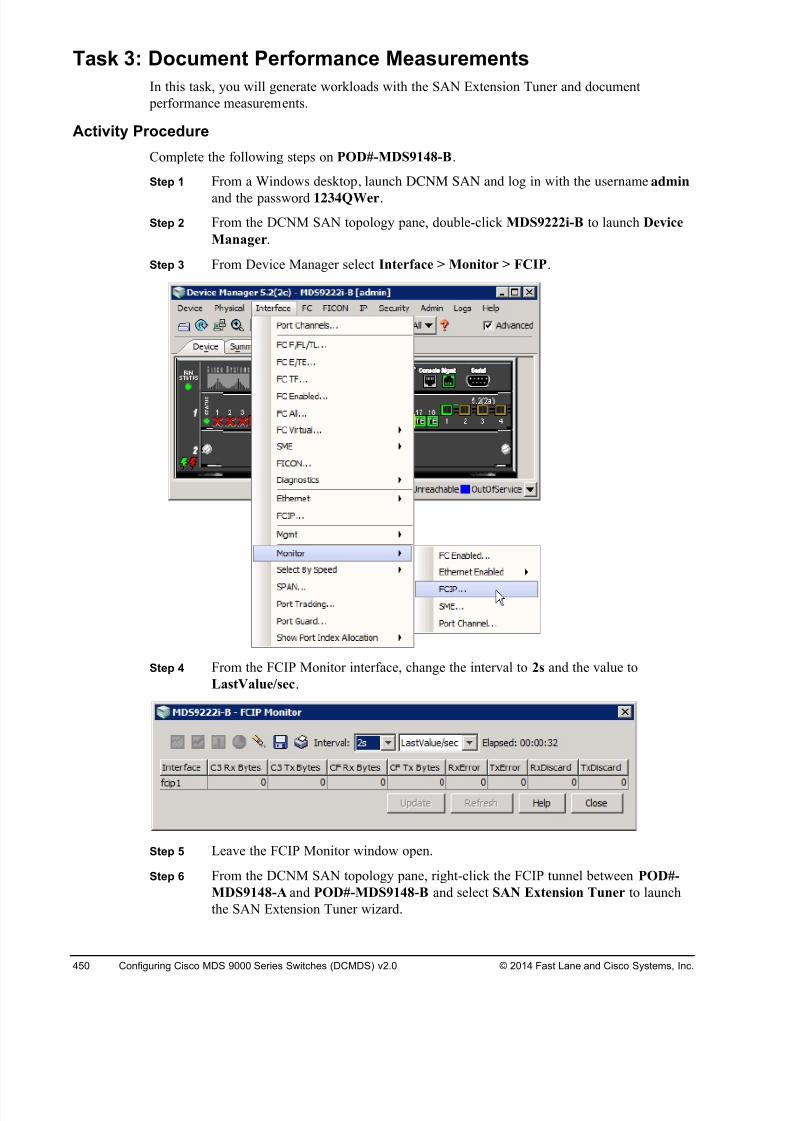
8/18/2019 FL_DCMDS_2.0.3_LG(1).pdf
http://slidepdf.com/reader/full/fldcmds203lg1pdf 450/482
450 Configuring Cisco MDS 9000 Series Switches (DCMDS) v2.0 © 2014 Fast Lane and Cisco Systems, Inc.
Task 3: Document Performance Measurements
In this task, you will generate workloads with the SAN Extension Tuner and document
performance measurements.
Activity Procedure
Complete the following steps on POD#-MDS9148-B.
Step 1 From a Windows desktop, launch DCNM SAN and log in with the username admin
and the password 1234QWer.
Step 2 From the DCNM SAN topology pane, double-click MDS9222i-B to launch Device
Manager.
Step 3 From Device Manager select Interface > Monitor > FCIP.
Step 4 From the FCIP Monitor interface, change the interval to 2s and the value to
LastValue/sec.
Step 5 Leave the FCIP Monitor window open.
Step 6 From the DCNM SAN topology pane, right-click the FCIP tunnel between POD#-
MDS9148-A and POD#-MDS9148-B and select SAN Extension Tuner to launch
the SAN Extension Tuner wizard.
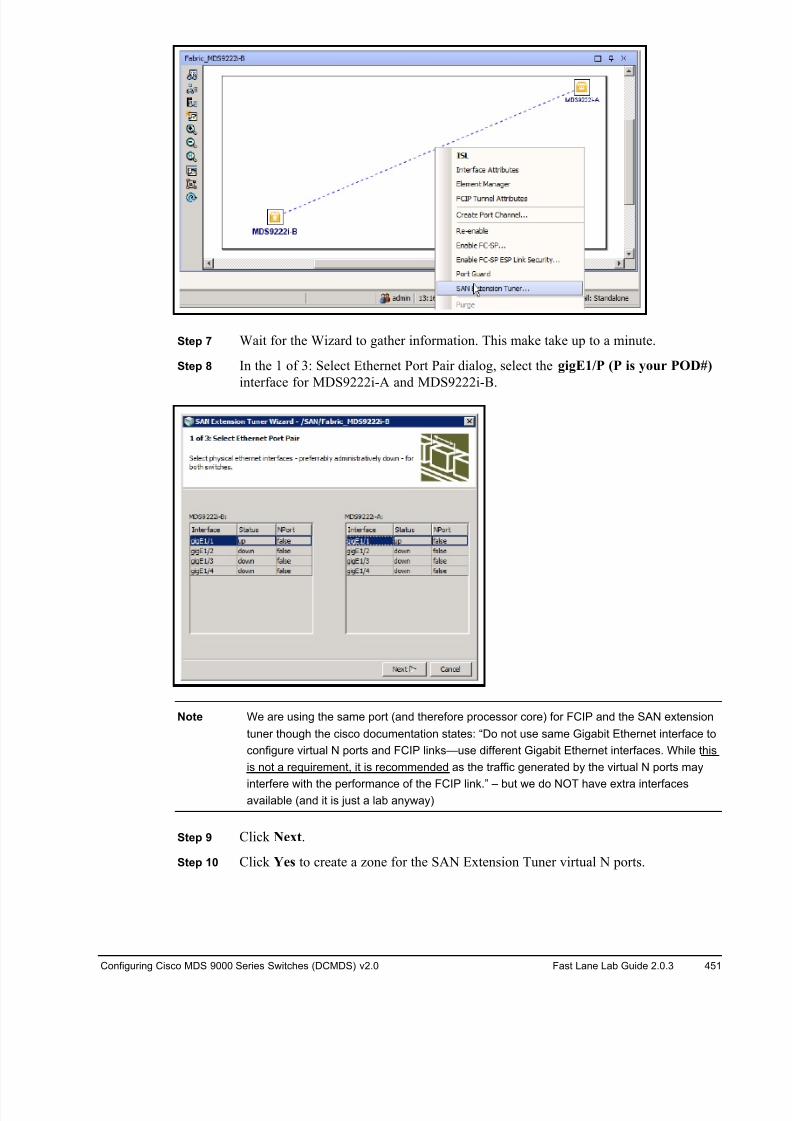
8/18/2019 FL_DCMDS_2.0.3_LG(1).pdf
http://slidepdf.com/reader/full/fldcmds203lg1pdf 451/482
Configuring Cisco MDS 9000 Series Switches (DCMDS) v2.0 Fast Lane Lab Guide 2.0.3 451
Step 7 Wait for the Wizard to gather information. This make take up to a minute.
Step 8 In the 1 of 3: Select Ethernet Port Pair dialog, select the gigE1/P (P is your POD#)
interface for MDS9222i-A and MDS9222i-B.
Note We are using the same port (and therefore processor core) for FCIP and the SAN extension
tuner though the cisco documentation states: “Do not use same Gigabit Ethernet interface to
configure virtual N ports and FCIP links—use different Gigabit Ethernet interfaces. While this
is not a requirement, it is recommended as the traffic generated by the virtual N ports may
interfere with the performance of the FCIP link.” – but we do NOT have extra interfacesavailable (and it is just a lab anyway)
Step 9 Click Next.
Step 10 Click Yes to create a zone for the SAN Extension Tuner virtual N ports.
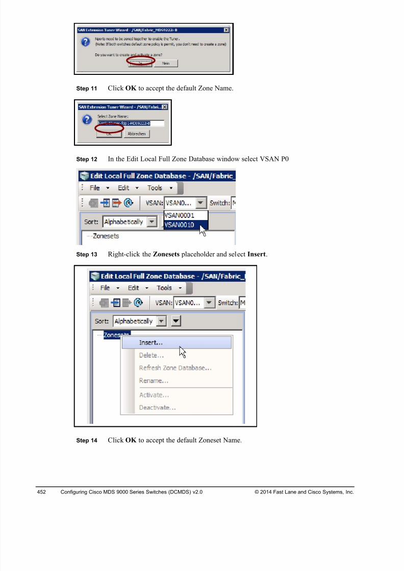
8/18/2019 FL_DCMDS_2.0.3_LG(1).pdf
http://slidepdf.com/reader/full/fldcmds203lg1pdf 452/482
452 Configuring Cisco MDS 9000 Series Switches (DCMDS) v2.0 © 2014 Fast Lane and Cisco Systems, Inc.
Step 11 Click OK to accept the default Zone Name.
Step 12 In the Edit Local Full Zone Database window select VSAN P0
Step 13 Right-click the Zonesets placeholder and select Insert.
Step 14 Click OK to accept the default Zoneset Name.
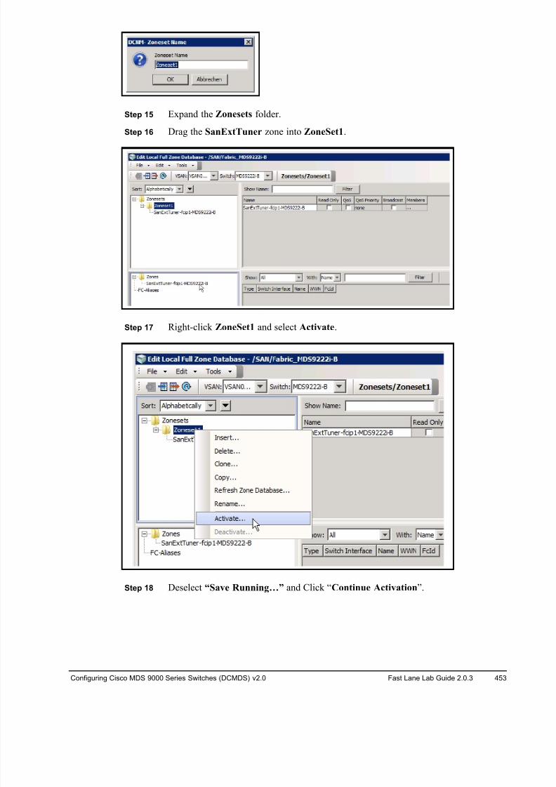
8/18/2019 FL_DCMDS_2.0.3_LG(1).pdf
http://slidepdf.com/reader/full/fldcmds203lg1pdf 453/482
Configuring Cisco MDS 9000 Series Switches (DCMDS) v2.0 Fast Lane Lab Guide 2.0.3 453
Step 15 Expand the Zonesets folder.
Step 16 Drag the SanExtTuner zone into ZoneSet1.
Step 17 Right-click ZoneSet1 and select Activate.
Step 18 Deselect “Save Running…” and Click “Continue Activation”.
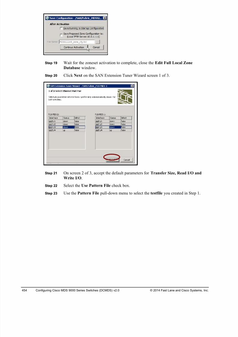
8/18/2019 FL_DCMDS_2.0.3_LG(1).pdf
http://slidepdf.com/reader/full/fldcmds203lg1pdf 454/482
454 Configuring Cisco MDS 9000 Series Switches (DCMDS) v2.0 © 2014 Fast Lane and Cisco Systems, Inc.
Step 19 Wait for the zoneset activation to complete, close the Edit Full Local Zone
Database window.
Step 20 Click Next on the SAN Extension Tuner Wizard screen 1 of 3.
Step 21 On screen 2 of 3, accept the default parameters for Transfer Size, Read I/O and
Write I/O.
Step 22 Select the Use Pattern File check box.
Step 23 Use the Pattern File pull-down menu to select the testfile you created in Step 1.
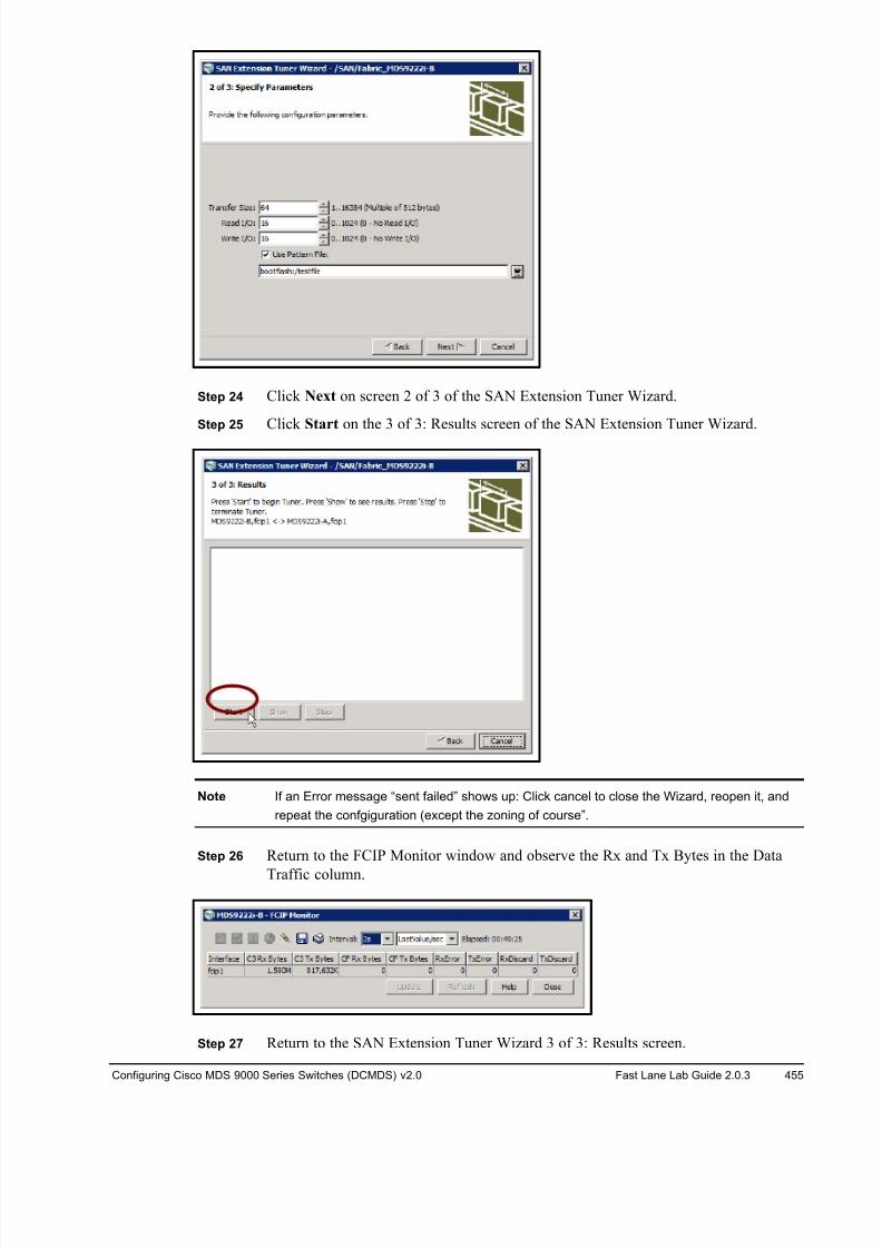
8/18/2019 FL_DCMDS_2.0.3_LG(1).pdf
http://slidepdf.com/reader/full/fldcmds203lg1pdf 455/482
Configuring Cisco MDS 9000 Series Switches (DCMDS) v2.0 Fast Lane Lab Guide 2.0.3 455
Step 24 Click Next on screen 2 of 3 of the SAN Extension Tuner Wizard.
Step 25 Click Start on the 3 of 3: Results screen of the SAN Extension Tuner Wizard.
Note If an Error message “sent failed” shows up: Click cancel to close the Wizard, reopen it, and
repeat the confgiguration (except the zoning of course”.
Step 26 Return to the FCIP Monitor window and observe the Rx and Tx Bytes in the Data
Traffic column.
Step 27 Return to the SAN Extension Tuner Wizard 3 of 3: Results screen.
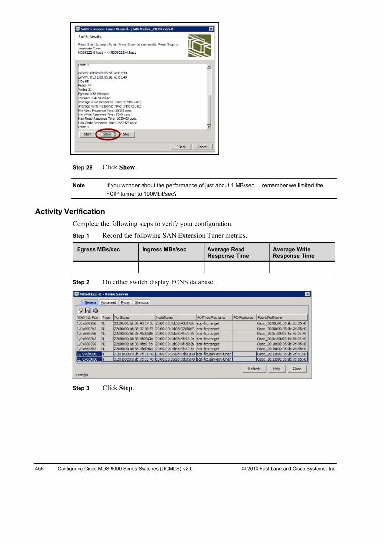
8/18/2019 FL_DCMDS_2.0.3_LG(1).pdf
http://slidepdf.com/reader/full/fldcmds203lg1pdf 456/482
456 Configuring Cisco MDS 9000 Series Switches (DCMDS) v2.0 © 2014 Fast Lane and Cisco Systems, Inc.
Step 28 Click Show.
Note If you wonder about the performance of just about 1 MB/sec! remember we limited the
FCIP tunnel to 100Mbit/sec?
Activity Verification
Complete the following steps to verify your configuration.
Step 1 Record the following SAN Extension Tuner metrics.
Egress MBs/sec Ingress MBs/sec Average ReadResponse Time
Average WriteResponse Time
Step 2 On either switch display FCNS database.
Step 3 Click Stop.
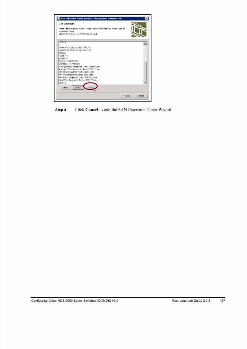
8/18/2019 FL_DCMDS_2.0.3_LG(1).pdf
http://slidepdf.com/reader/full/fldcmds203lg1pdf 457/482
Configuring Cisco MDS 9000 Series Switches (DCMDS) v2.0 Fast Lane Lab Guide 2.0.3 457
Step 4 Click Cancel to exit the SAN Extension Tuner Wizard.
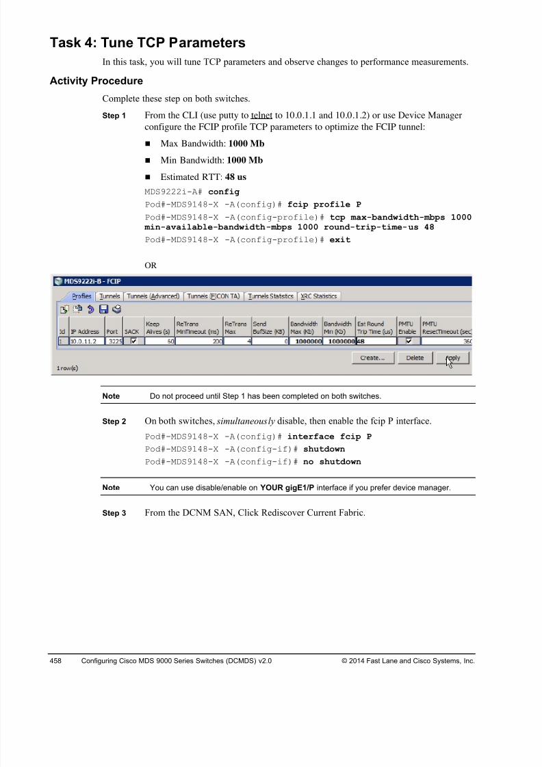
8/18/2019 FL_DCMDS_2.0.3_LG(1).pdf
http://slidepdf.com/reader/full/fldcmds203lg1pdf 458/482
458 Configuring Cisco MDS 9000 Series Switches (DCMDS) v2.0 © 2014 Fast Lane and Cisco Systems, Inc.
Task 4: Tune TCP Parameters
In this task, you will tune TCP parameters and observe changes to performance measurements.
Activity Procedure
Complete these step on both switches.
Step 1 From the CLI (use putty to telnet to 10.0.1.1 and 10.0.1.2) or use Device Manager
configure the FCIP profile TCP parameters to optimize the FCIP tunnel:
! Max Bandwidth: 1000 Mb
! Min Bandwidth: 1000 Mb
! Estimated RTT: 48 us
MDS9222i-A# config
Pod#-MDS9148-X -A(config)# fcip profile P
Pod#-MDS9148-X -A(config-profile)# tcp max-bandwidth-mbps 1000 min-available-bandwidth-mbps 1000 round-trip-time-us 48
Pod#-MDS9148-X -A(config-profile)# exit
OR
Note Do not proceed until Step 1 has been completed on both switches.
Step 2 On both switches, simultaneously disable, then enable the fcip P interface.
Pod#-MDS9148-X -A(config)# interface fcip P
Pod#-MDS9148-X -A(config-if)# shutdown
Pod#-MDS9148-X -A(config-if)# no shutdown
Note You can use disable/enable on YOUR gigE1/P interface if you prefer device manager.
Step 3 From the DCNM SAN, Click Rediscover Current Fabric.
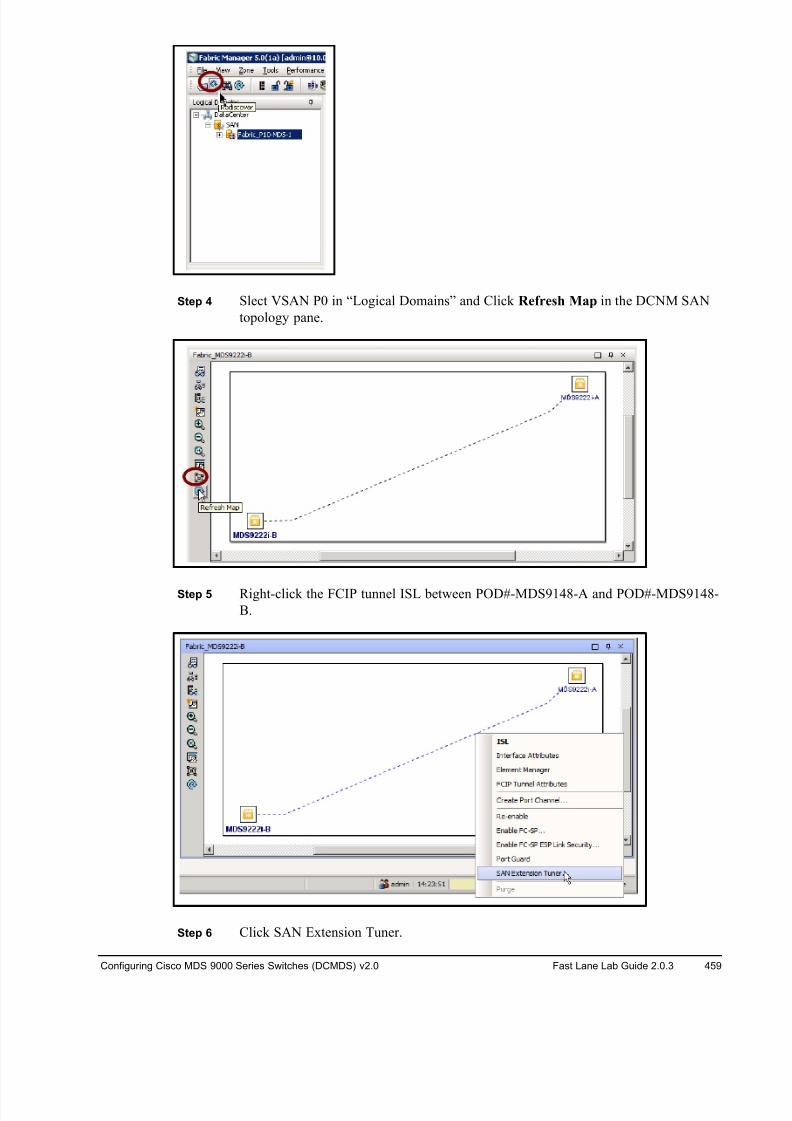
8/18/2019 FL_DCMDS_2.0.3_LG(1).pdf
http://slidepdf.com/reader/full/fldcmds203lg1pdf 459/482
Configuring Cisco MDS 9000 Series Switches (DCMDS) v2.0 Fast Lane Lab Guide 2.0.3 459
Step 4 Slect VSAN P0 in “Logical Domains” and Click Refresh Map in the DCNM SAN
topology pane.
Step 5 Right-click the FCIP tunnel ISL between POD#-MDS9148-A and POD#-MDS9148-B.
Step 6 Click SAN Extension Tuner.
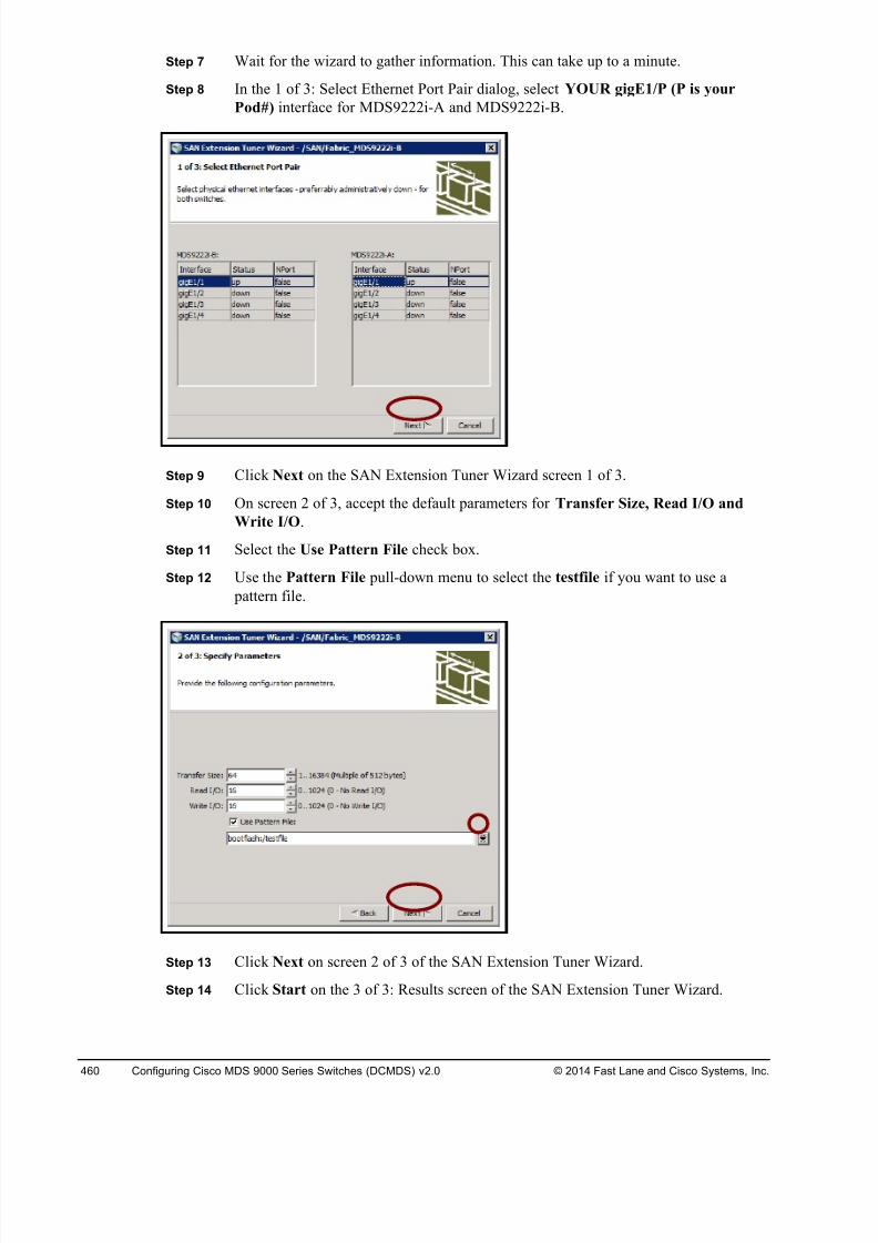
8/18/2019 FL_DCMDS_2.0.3_LG(1).pdf
http://slidepdf.com/reader/full/fldcmds203lg1pdf 460/482
460 Configuring Cisco MDS 9000 Series Switches (DCMDS) v2.0 © 2014 Fast Lane and Cisco Systems, Inc.
Step 7 Wait for the wizard to gather information. This can take up to a minute.
Step 8 In the 1 of 3: Select Ethernet Port Pair dialog, select YOUR gigE1/P (P is your
Pod#) interface for MDS9222i-A and MDS9222i-B.
Step 9 Click Next on the SAN Extension Tuner Wizard screen 1 of 3.
Step 10 On screen 2 of 3, accept the default parameters for Transfer Size, Read I/O and
Write I/O.
Step 11 Select the Use Pattern File check box.
Step 12 Use the Pattern File pull-down menu to select the testfile if you want to use a
pattern file.
Step 13 Click Next on screen 2 of 3 of the SAN Extension Tuner Wizard.
Step 14 Click Start on the 3 of 3: Results screen of the SAN Extension Tuner Wizard.
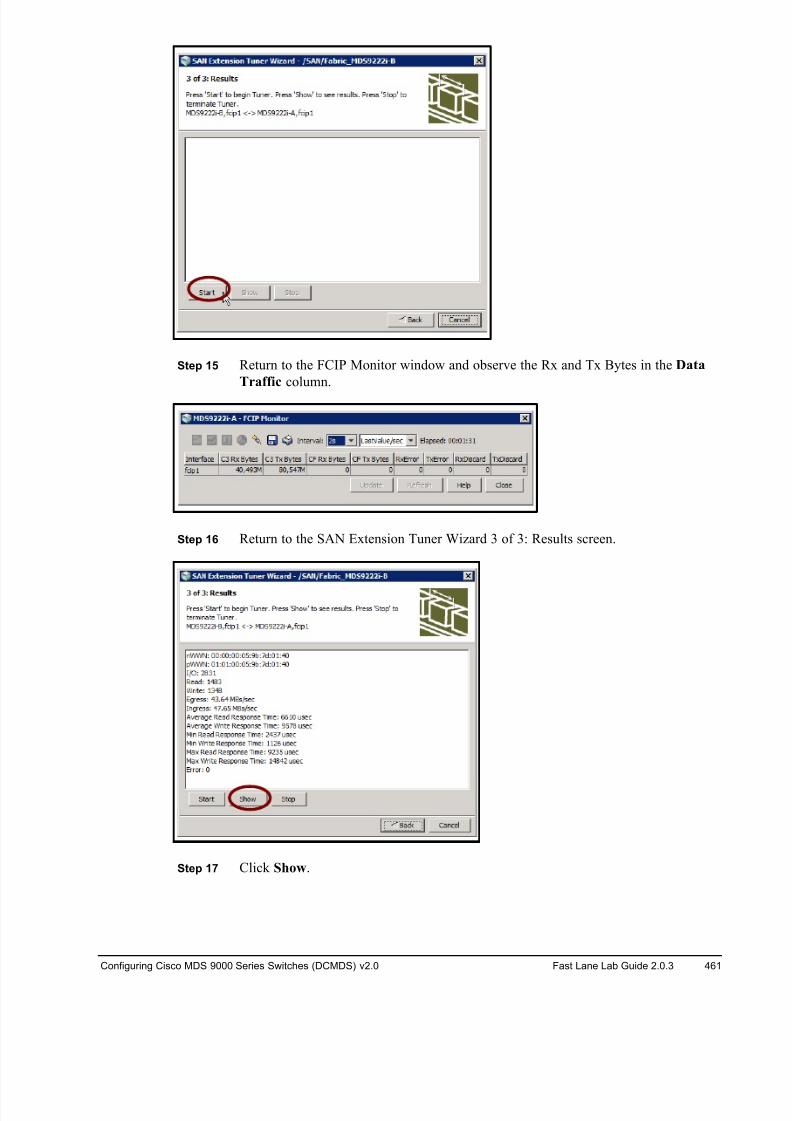
8/18/2019 FL_DCMDS_2.0.3_LG(1).pdf
http://slidepdf.com/reader/full/fldcmds203lg1pdf 461/482
Configuring Cisco MDS 9000 Series Switches (DCMDS) v2.0 Fast Lane Lab Guide 2.0.3 461
Step 15 Return to the FCIP Monitor window and observe the Rx and Tx Bytes in the Data
Traffic column.
Step 16 Return to the SAN Extension Tuner Wizard 3 of 3: Results screen.
Step 17 Click Show.
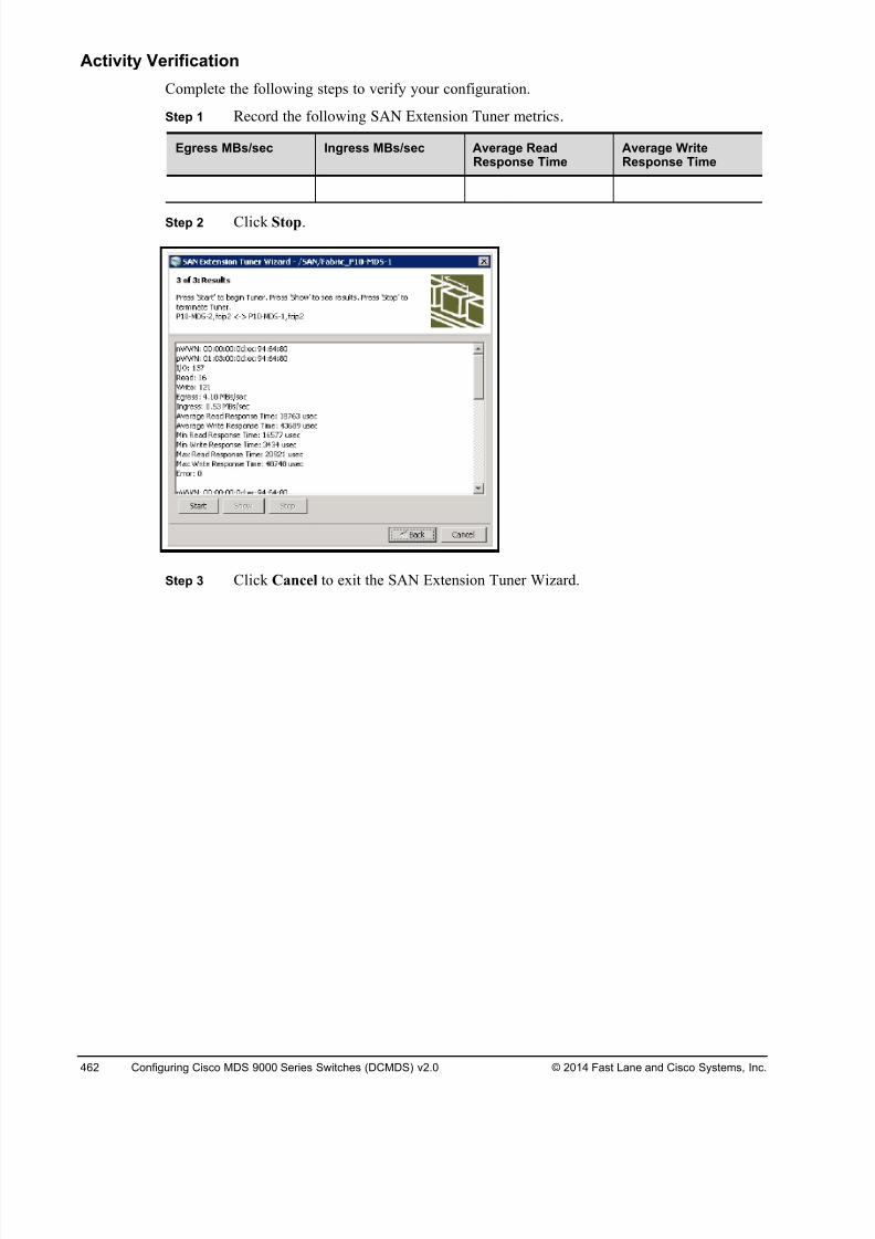
8/18/2019 FL_DCMDS_2.0.3_LG(1).pdf
http://slidepdf.com/reader/full/fldcmds203lg1pdf 462/482
462 Configuring Cisco MDS 9000 Series Switches (DCMDS) v2.0 © 2014 Fast Lane and Cisco Systems, Inc.
Activity Verification
Complete the following steps to verify your configuration.
Step 1 Record the following SAN Extension Tuner metrics.
Egress MBs/sec Ingress MBs/sec Average ReadResponse Time
Average WriteResponse Time
Step 2 Click Stop.
Step 3 Click Cancel to exit the SAN Extension Tuner Wizard.
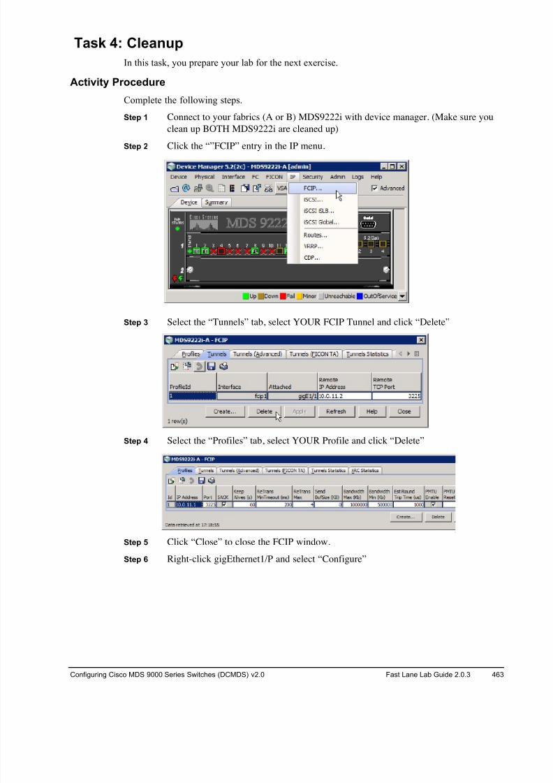
8/18/2019 FL_DCMDS_2.0.3_LG(1).pdf
http://slidepdf.com/reader/full/fldcmds203lg1pdf 463/482
Configuring Cisco MDS 9000 Series Switches (DCMDS) v2.0 Fast Lane Lab Guide 2.0.3 463
Task 4: Cleanup
In this task, you prepare your lab for the next exercise.
Activity Procedure
Complete the following steps.
Step 1 Connect to your fabrics (A or B) MDS9222i with device manager. (Make sure you
clean up BOTH MDS9222i are cleaned up)
Step 2 Click the “”FCIP” entry in the IP menu.
Step 3 Select the “Tunnels” tab, select YOUR FCIP Tunnel and click “Delete”
Step 4 Select the “Profiles” tab, select YOUR Profile and click “Delete”
Step 5 Click “Close” to close the FCIP window.
Step 6 Right-click gigEthernet1/P and select “Configure”
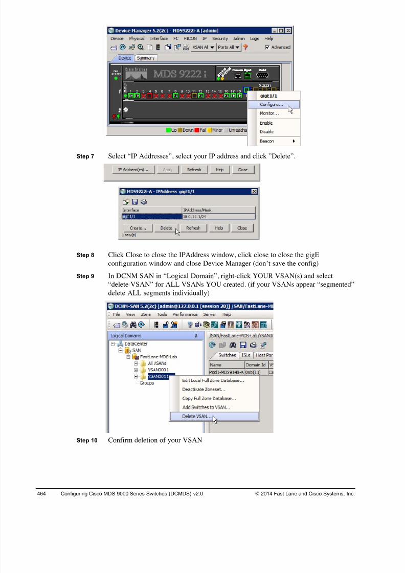
8/18/2019 FL_DCMDS_2.0.3_LG(1).pdf
http://slidepdf.com/reader/full/fldcmds203lg1pdf 464/482
464 Configuring Cisco MDS 9000 Series Switches (DCMDS) v2.0 © 2014 Fast Lane and Cisco Systems, Inc.
Step 7 Select “IP Addresses”, select your IP address and click ”Delete”.
Step 8 Click Close to close the IPAddress window, click close to close the gigE
configuration window and close Device Manager (don’t save the config)
Step 9 In DCNM SAN in “Logical Domain”, right-click YOUR VSAN(s) and select
“delete VSAN” for ALL VSANs YOU created. (if your VSANs appear “segmented”
delete ALL segments individually)
Step 10 Confirm deletion of your VSAN
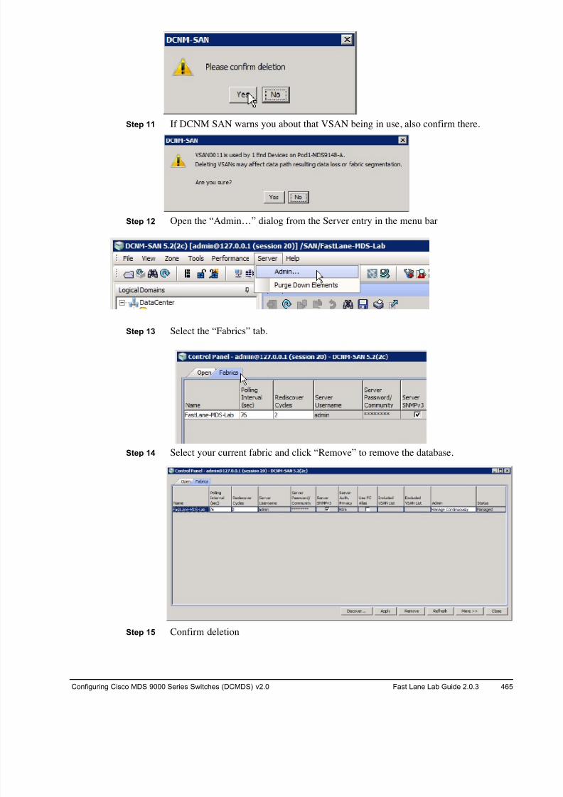
8/18/2019 FL_DCMDS_2.0.3_LG(1).pdf
http://slidepdf.com/reader/full/fldcmds203lg1pdf 465/482
Configuring Cisco MDS 9000 Series Switches (DCMDS) v2.0 Fast Lane Lab Guide 2.0.3 465
Step 11 If DCNM SAN warns you about that VSAN being in use, also confirm there.
Step 12 Open the “Admin…” dialog from the Server entry in the menu bar
Step 13 Select the “Fabrics” tab.
Step 14 Select your current fabric and click “Remove” to remove the database.
Step 15 Confirm deletion
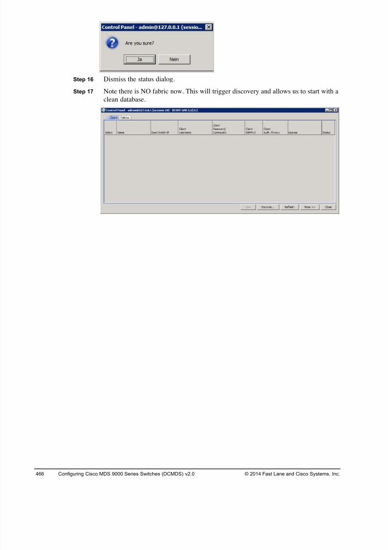
8/18/2019 FL_DCMDS_2.0.3_LG(1).pdf
http://slidepdf.com/reader/full/fldcmds203lg1pdf 466/482
466 Configuring Cisco MDS 9000 Series Switches (DCMDS) v2.0 © 2014 Fast Lane and Cisco Systems, Inc.
Step 16 Dismiss the status dialog.
Step 17 Note there is NO fabric now. This will trigger discovery and allows us to start with a
clean database.
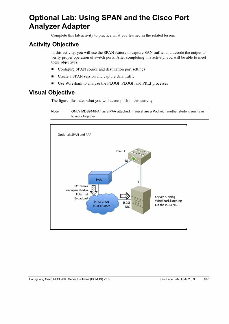
8/18/2019 FL_DCMDS_2.0.3_LG(1).pdf
http://slidepdf.com/reader/full/fldcmds203lg1pdf 467/482
Configuring Cisco MDS 9000 Series Switches (DCMDS) v2.0 Fast Lane Lab Guide 2.0.3 467
Optional Lab: Using SPAN and the Cisco PortAnalyzer Adapter
Complete this lab activity to practice what you learned in the related lesson.
Activity Objective
In this activity, you will use the SPAN feature to capture SAN traffic, and decode the output to
verify proper operation of switch ports. After completing this activity, you will be able to meetthese objectives:
! Configure SPAN source and destination port settings
! Create a SPAN session and capture data traffic
! Use Wireshark to analyze the FLOGI, PLOGI, and PRLI processes
Visual Objective
The figure illustrates what you will accomplish in this activity.
Note ONLY MDS9148-A has a PAA attached. If you share a Pod with another student you have
to work together.
!"#$%&'( *+,- &%. +,,
/
/
0/123,
12
4*5*6 78,-
/9:9:/+:9;<1
+,,
4*5*6
-65
=5 >?&@AB
A%C&"BD'&EA. 4%
FEGA?%AE
H?$&.C&BE *A?IA? ?D%%4%J
K4?A*G&?L '4BEA%4%J
!% EGA 4*5*6 -65
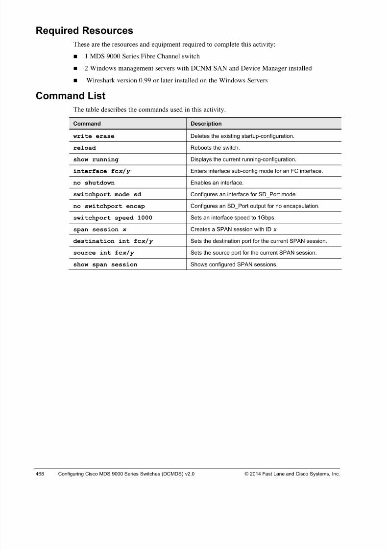
8/18/2019 FL_DCMDS_2.0.3_LG(1).pdf
http://slidepdf.com/reader/full/fldcmds203lg1pdf 468/482
468 Configuring Cisco MDS 9000 Series Switches (DCMDS) v2.0 © 2014 Fast Lane and Cisco Systems, Inc.
Required Resources
These are the resources and equipment required to complete this activity:
! 1 MDS 9000 Series Fibre Channel switch
! 2 Windows management servers with DCNM SAN and Device Manager installed
! Wireshark version 0.99 or later installed on the Windows Servers
Command List The table describes the commands used in this activity.
Command Description
write erase Deletes the existing startup-configuration.
reload Reboots the switch.
show running Displays the current running-configuration.
interface fcx / y Enters interface sub-config mode for an FC interface.
no shutdown Enables an interface.
switchport mode sd Configures an interface for SD_Port mode.
no switchport encap Configures an SD_Port output for no encapsulation.
switchport speed 1000 Sets an interface speed to 1Gbps.
span session x Creates a SPAN session with ID x.
destination int fcx / y Sets the destination port for the current SPAN session.
source int fcx / y Sets the source port for the current SPAN session.
show span session Shows configured SPAN sessions.
8/18/2019 FL_DCMDS_2.0.3_LG(1).pdf
http://slidepdf.com/reader/full/fldcmds203lg1pdf 469/482
Configuring Cisco MDS 9000 Series Switches (DCMDS) v2.0 Fast Lane Lab Guide 2.0.3 469
Task 1: Complete the Initial Switch Configuration
In this task, you will use the CLI to complete the initial switch configuration process.
Note If you are working in teams, you can take turns running through this lab exercise or join to
form one team. This lab can only be run on POD#-MDS9148-A. POD#-MDS9148-B does
not play a part in this exercise.
Activity ProcedureComplete the following steps on POD#-MDS9148-A.
Step 1 Open a console session by clicking the blue switch icon in the remote lab GUI.
Note If the switch asks for username and password at this step log in with user “admin” and
password “1234QWer”, erase the configuration and reboot.
Step 2 After the switch reboots, it will automatically launch the setup process. Answer the
questions according to the following example, replacing your pod number and
switch ID where appropriate.
---- System Admin Account Setup ----
Do you want to enforce secure password standard (yes/no) [y]: y
Enter the password for "admin": 1234QWer < note QW is UPPERCASE
Confirm the password for "admin":1234QWer
Caution DO NOT USE ANY OTHER PASSWORD. This may force the lab support management
software to recover passwords and your configuration may be deleted.
--- Basic System Configuration Dialog ---
This setup utility will guide you through the basic configuration ofthe system. Setup configures only enough connectivity for managementof the system.
Please register Cisco MDS 9000 Family devices promptly with yoursupplier. Failure to register may affect response times for initialservice calls. MDS devices must be registered to receive entitledsupport services.
Press Enter at anytime to skip a dialog. Use ctrl-c at anytime to skipthe remaining dialogs.
Would you like to enter the basic configuration dialog (yes/no): y
Create another login account (yes/no) [n]: <Enter>
Configure read-only SNMP community string (yes/no) [n]: <Enter>
Configure read-write SNMP community string (yes/no) [n]: <Enter>
Enter the switch name: Pod#-MDS9148-A (where # is your pod number; for example:
Pod1-MDS9148-A)
Continue with Out-of-band (mgmt0) management configuration? (yes/no)[y]: <Enter>
Mgmt0 IPv4 address : <10.0.1.P1>
(where P is your Pod#)
Mgmt0 IPv4 netmask : 255.255.255.0
8/18/2019 FL_DCMDS_2.0.3_LG(1).pdf
http://slidepdf.com/reader/full/fldcmds203lg1pdf 470/482
470 Configuring Cisco MDS 9000 Series Switches (DCMDS) v2.0 © 2014 Fast Lane and Cisco Systems, Inc.
Configure the default gateway? (yes/no) [y]: <No>
Configure advanced IP options? (yes/no) [n]: <Enter>
Enable the ssh service? (yes/no) [y]: <No>
Enable the telnet service? (yes/no) [n]: <Yes>
Enable the http-server? (yes/no) [y]: <Enter>
Configure clock? (yes/no) [n]: <Enter>
Configure timezone? (yes/no) [n]: <Enter>
Configure summertime? (yes/no) [n]: <Enter>
Configure the ntp server? (yes/no) [n]: <Enter>
Configure default switchport interface state (shut/noshut) [shut]: <Enter>
Configure default switchport trunk mode (on/off/auto) [on]: <Enter>
Configure default switchport port mode F (yes/no) [n]: <Enter>
Configure default zone policy (permit/deny) [deny]: <Enter>
Enable full zoneset distribution (yes/no) [n]: <Enter>
Configure default zone mode (basic/enhanced) [basic]: <Enter>
Step 3 A summary of the configuration will be displayed:
The following configuration will be applied:
password strength-checkswitchname POD#-MDS9148-A
interface mgmt0
ip address 10.0.1.PN 255.255.255.0
no shutdown
no feature ssh
feature telnet
feature http-server
system default switchport shutdown
system default switchport trunk mode on
no system default zone default-zone permit
no system default zone distribute full
no system default zone mode enhanced
Step 4 Press Enter twice to save the configuration.
Would you like to edit the configuration? (yes/no) [n]: <Enter>
Use this configuration and save it? (yes/no) [y]: <Enter>
Step 5 Log in to the console using the username admin and the password 1234QWer
Step 6 Remove the licenses from ports 13-16 and assign a license to port 48.
Pod#-MDS9148-A# conf
Enter configuration commands, one per line. End with CNTL/Z.
Pod#-MDS9148-A(config)# int fc 1/13-16 Pod#-MDS9148-A(config-if)# no port-license acquire
Pod#-MDS9148-A(config-if)# exit
Pod#-MDS9148-A(config)# int fc 1/48
Pod#-MDS9148-A(config-if)# port-license acquire
Pod#-MDS9148-A(config-if)# end
Pod#-MDS9148-A#
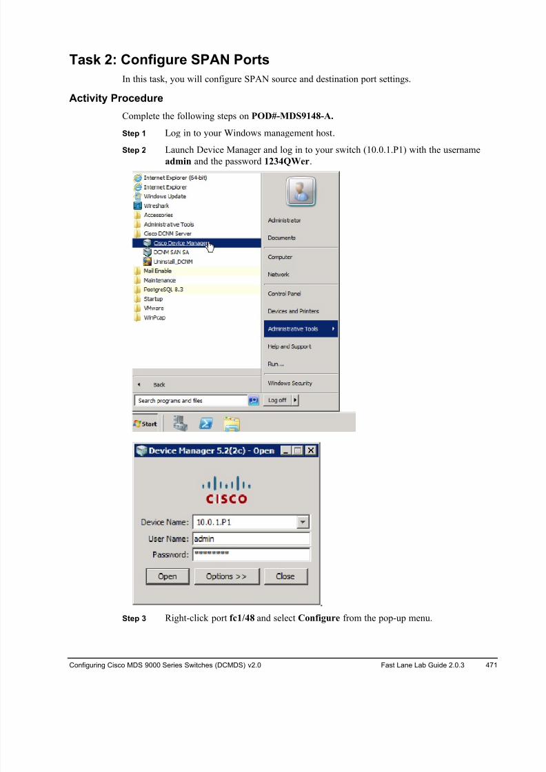
8/18/2019 FL_DCMDS_2.0.3_LG(1).pdf
http://slidepdf.com/reader/full/fldcmds203lg1pdf 471/482
Configuring Cisco MDS 9000 Series Switches (DCMDS) v2.0 Fast Lane Lab Guide 2.0.3 471
Task 2: Configure SPAN Ports
In this task, you will configure SPAN source and destination port settings.
Activity Procedure
Complete the following steps on POD#-MDS9148-A.
Step 1 Log in to your Windows management host.Step 2 Launch Device Manager and log in to your switch (10.0.1.P1) with the username
admin and the password 1234QWer.
Step 3 Right-click port fc1/48 and select Configure from the pop-up menu.
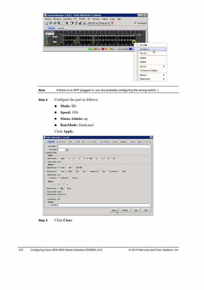
8/18/2019 FL_DCMDS_2.0.3_LG(1).pdf
http://slidepdf.com/reader/full/fldcmds203lg1pdf 472/482
472 Configuring Cisco MDS 9000 Series Switches (DCMDS) v2.0 © 2014 Fast Lane and Cisco Systems, Inc.
Note If there is no SFP plugged in, you are probably configuring the wrong switch ;)
Step 4 Configure the port as follows:
! Mode: SD
! Speed: 1Gb
! Status Admin: up
! RateMode: Dedicated
Click Apply.
Step 5 Click Close.
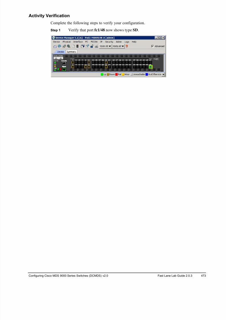
8/18/2019 FL_DCMDS_2.0.3_LG(1).pdf
http://slidepdf.com/reader/full/fldcmds203lg1pdf 473/482
Configuring Cisco MDS 9000 Series Switches (DCMDS) v2.0 Fast Lane Lab Guide 2.0.3 473
Activity Verification
Complete the following steps to verify your configuration.
Step 1 Verify that port fc1/48 now shows type SD.
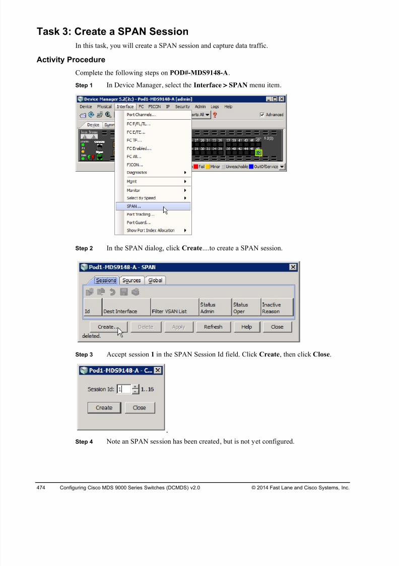
8/18/2019 FL_DCMDS_2.0.3_LG(1).pdf
http://slidepdf.com/reader/full/fldcmds203lg1pdf 474/482
474 Configuring Cisco MDS 9000 Series Switches (DCMDS) v2.0 © 2014 Fast Lane and Cisco Systems, Inc.
Task 3: Create a SPAN Session
In this task, you will create a SPAN session and capture data traffic.
Activity Procedure
Complete the following steps on POD#-MDS9148-A.
Step 1 In Device Manager, select the Interface > SPAN menu item.
Step 2 In the SPAN dialog, click Create....to create a SPAN session.
Step 3 Accept session 1 in the SPAN Session Id field. Click Create, then click Close.
Step 4 Note an SPAN session has been created, but is not yet configured.
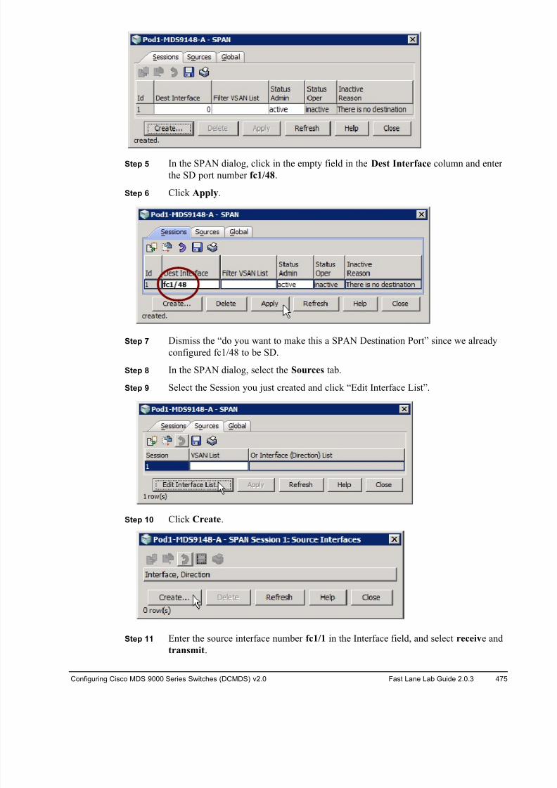
8/18/2019 FL_DCMDS_2.0.3_LG(1).pdf
http://slidepdf.com/reader/full/fldcmds203lg1pdf 475/482
Configuring Cisco MDS 9000 Series Switches (DCMDS) v2.0 Fast Lane Lab Guide 2.0.3 475
Step 5 In the SPAN dialog, click in the empty field in the Dest Interface column and enter
the SD port number fc1/48.
Step 6 Click Apply.
Step 7 Dismiss the “do you want to make this a SPAN Destination Port” since we already
configured fc1/48 to be SD.
Step 8 In the SPAN dialog, select the Sources tab.
Step 9 Select the Session you just created and click “Edit Interface List”.
Step 10 Click Create.
Step 11 Enter the source interface number fc1/1 in the Interface field, and select receive and
transmit.
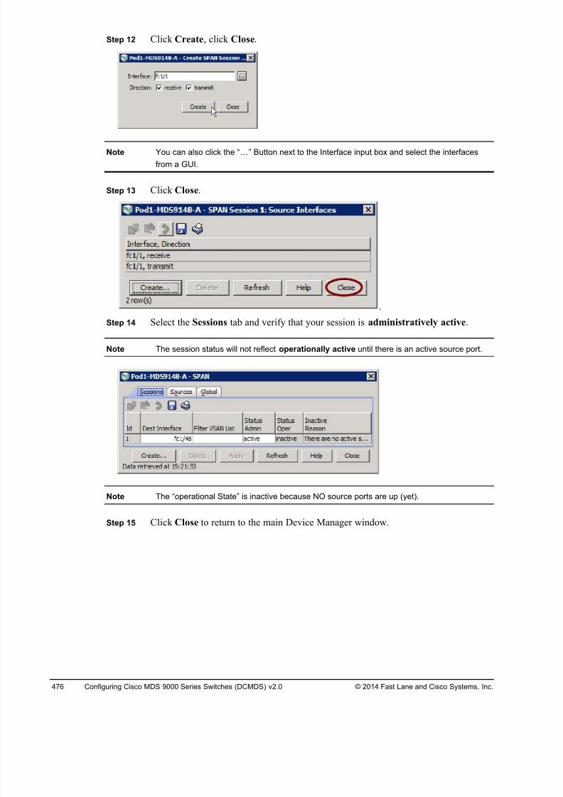
8/18/2019 FL_DCMDS_2.0.3_LG(1).pdf
http://slidepdf.com/reader/full/fldcmds203lg1pdf 476/482
476 Configuring Cisco MDS 9000 Series Switches (DCMDS) v2.0 © 2014 Fast Lane and Cisco Systems, Inc.
Step 12 Click Create, click Close.
Note You can also click the “!” Button next to the Interface input box and select the interfaces
from a GUI.
Step 13 Click Close.
Step 14 Select the Sessions tab and verify that your session is administratively active.
Note The session status will not reflect operationally active until there is an active source port.
Note The “operational State” is inactive because NO source ports are up (yet).
Step 15 Click Close to return to the main Device Manager window.
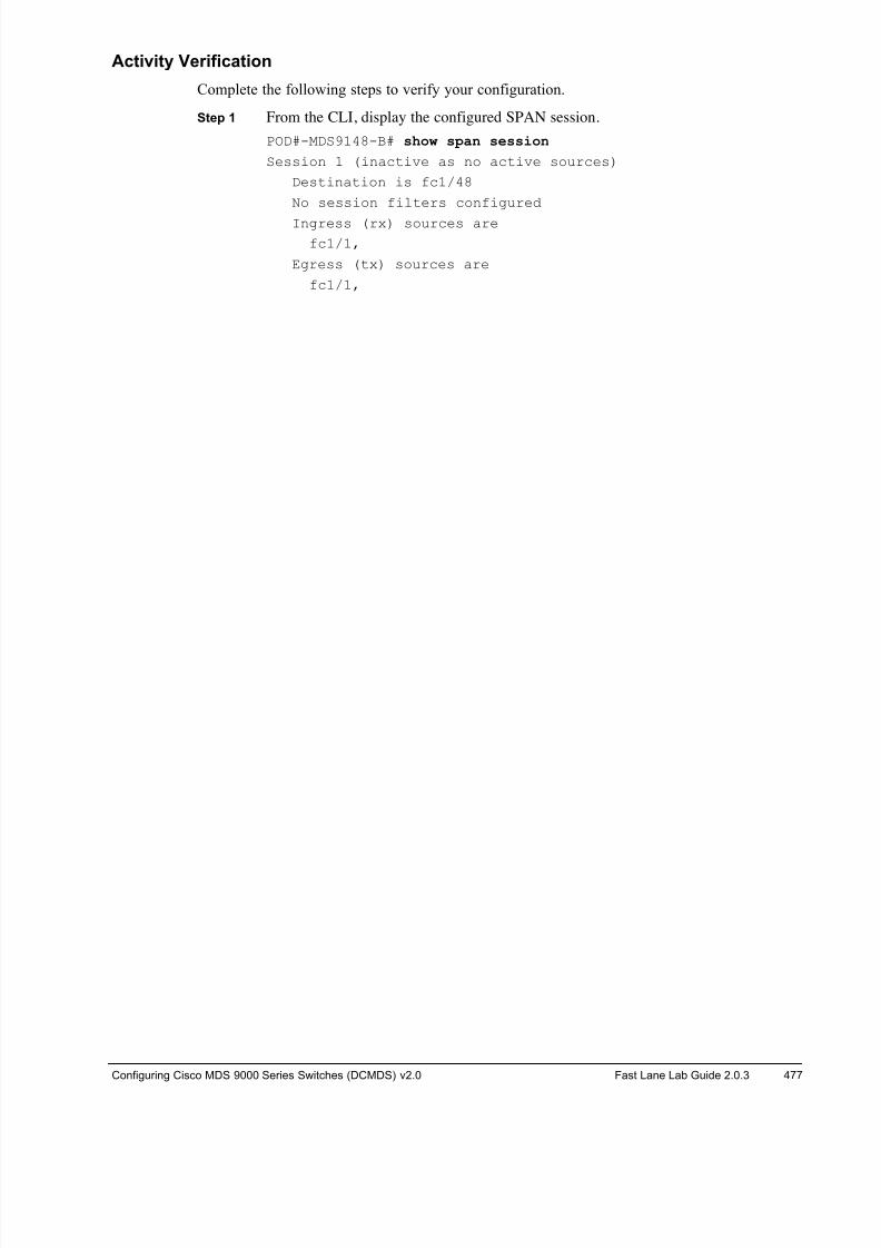
8/18/2019 FL_DCMDS_2.0.3_LG(1).pdf
http://slidepdf.com/reader/full/fldcmds203lg1pdf 477/482
Configuring Cisco MDS 9000 Series Switches (DCMDS) v2.0 Fast Lane Lab Guide 2.0.3 477
Activity Verification
Complete the following steps to verify your configuration.
Step 1 From the CLI, display the configured SPAN session.
POD#-MDS9148-B# show span session
Session 1 (inactive as no active sources)
Destination is fc1/48
No session filters configured
Ingress (rx) sources are
fc1/1,
Egress (tx) sources are
fc1/1,
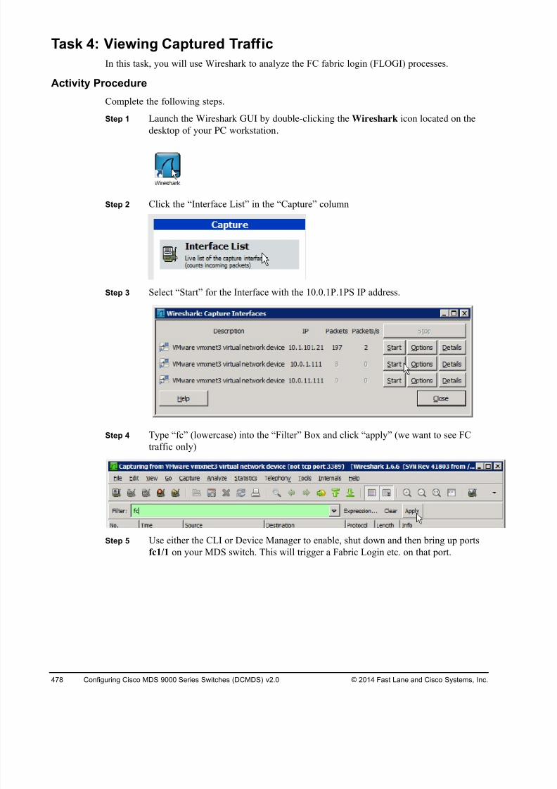
8/18/2019 FL_DCMDS_2.0.3_LG(1).pdf
http://slidepdf.com/reader/full/fldcmds203lg1pdf 478/482
478 Configuring Cisco MDS 9000 Series Switches (DCMDS) v2.0 © 2014 Fast Lane and Cisco Systems, Inc.
Task 4: Viewing Captured Traff ic
In this task, you will use Wireshark to analyze the FC fabric login (FLOGI) processes.
Activity Procedure
Complete the following steps.
Step 1 Launch the Wireshark GUI by double-clicking the Wireshark icon located on the
desktop of your PC workstation.
Step 2 Click the “Interface List” in the “Capture” column
Step 3 Select “Start” for the Interface with the 10.0.1P.1PS IP address.
Step 4 Type “fc” (lowercase) into the “Filter” Box and click “apply” (we want to see FC
traffic only)
Step 5 Use either the CLI or Device Manager to enable, shut down and then bring up ports
fc1/1 on your MDS switch. This will trigger a Fabric Login etc. on that port.
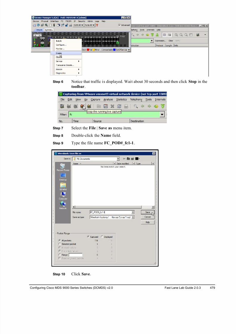
8/18/2019 FL_DCMDS_2.0.3_LG(1).pdf
http://slidepdf.com/reader/full/fldcmds203lg1pdf 479/482
Configuring Cisco MDS 9000 Series Switches (DCMDS) v2.0 Fast Lane Lab Guide 2.0.3 479
Step 6 Notice that traffic is displayed. Wait about 30 seconds and then click Stop in the
toolbar.
Step 7 Select the File | Save as menu item.
Step 8 Double-click the Name field.
Step 9 Type the file name FC_POD#_fc1-1.
Step 10 Click Save.
8/18/2019 FL_DCMDS_2.0.3_LG(1).pdf
http://slidepdf.com/reader/full/fldcmds203lg1pdf 480/482
480 Configuring Cisco MDS 9000 Series Switches (DCMDS) v2.0 © 2014 Fast Lane and Cisco Systems, Inc.
You now have a file that can be opened by Wireshark at any time. Next, create a display filter
to display only FC frames.
Note The Port Analyzer Adapter (PAA) must truncate the frame in order to encapsulate it into an
Ethernet packet. This can cause malformed packets. You may notice some of the packets
are listed as malformed due to the truncation setting on the PAA.
8/18/2019 FL_DCMDS_2.0.3_LG(1).pdf
http://slidepdf.com/reader/full/fldcmds203lg1pdf 481/482
Configuring Cisco MDS 9000 Series Switches (DCMDS) v2.0 Fast Lane Lab Guide 2.0.3 481
Task 5
(optional): Analyze Fibre Channel Traffic
Complete the following steps to analyze a FLOGI trace.
Step 1 Select an FLOGI frame.
Step 2 What is the well-known address of the Fabric Login Server? _ ________
Step 3 What port address was assigned by the Fabric during FLOGI? __ _______
Step 4 What OX_ID was used for this exchange? __ _______
Step 5 Click the plus sign next to the “FC ELS” section in the frame detail pane to expand
the ELS section.
Step 6 How many buffer-to-buffer credits does this port allow? __ _______
Step 7 What Classes of Service does this port support? __ _______
Step 8 Complete the following steps to analyze a PLOGI trace.
Step 9 Select a PLOGI frame.
Step 10 Click the plus sign next to the “Fibre Channel” section in the frame detail pane.
Step 11 Click the plus sign next to the “FC ELS” section in the frame detail pane.
Step 12 What is the well-known address of the Directory/Name Server? __ _______
Step 13 What OX_ID was used for this exchange? __ _______
Step 14 What buffer-to-buffer credit method (BBM) does this port use? __ _______
Step 15 What is the maximum number of concurrent sequences that the fabric will support
for this port? __ _______
Step 16 What is the maximum number of concurrent sequences that the fabric will support
for this port in class 2? __ _______
Step 17 What is the maximum number of concurrent sequences that the fabric will support
for this port in class 3? __ _______
Complete the following steps to analyze a PRLI trace.
Step 18 Select a PRLI frame.
Step 19 Click the plus sign next to the “Fibre Channel” section in the frame detail pane.
Step 20 Click the plus sign next to the “FC ELS” section in the frame detail pane.
Step 21 What OX_ID was used for this exchange? __ _______
Step 22 What is the Source address of this frame? __ _______
Step 23 What is the Destination address of this frame? __ _______
Step 24 Examine the output of the FC ELS - Service Parameter page 0, Flags field. What
does the FCP Flag describe?
______________________________________________________________
Step 25 Examine the output of the FC ELS - Service Parameter page 0, Flags field. What
does the FCP Flag describe?
______________________________________________________________
Step 26 What is the Response code contained in the ACC? __ _______
Step 27 Was an image pair established during this exchange? __ _______
8/18/2019 FL_DCMDS_2.0.3_LG(1).pdf
http://slidepdf.com/reader/full/fldcmds203lg1pdf 482/482
Step 28 On the POD#-MDS9148-B, at the CLI prompt, enter configuration mode and delete
the SPAN session.
POD#-MDS9148-B# config
POD#-MDS9148-B(config)# no span session 1
POD#-MDS9148-B(config)# end
![INTA_PT_89_Manual_de_Fertilidad[1] (1).pdf](https://img.pdfslide.tips/doc/110x75/55cf9138550346f57b8ba58d/intapt89manualdefertilidad1-1pdf.jpg)


![FICHERO_DE_TALENTOS_COLIMA[1] (1).pdf](https://img.pdfslide.tips/doc/110x75/55cf977b550346d03391dd53/ficherodetalentoscolima1-1pdf.jpg)