Embed Size (px)
Citation preview
8/8/2019 HDAudioDdi11
http://slidepdf.com/reader/full/hdaudioddi11 1/69
Microsoft Device Driver Interfacefor HD Audio
Windows Vista RC1 Version - September 25, 2006
Abstract
This document presents programming guidelines and a set of reference pages for the Intel High Definition (HD) Audio device driver interface (DDI). Audio and modemdrivers call the routines in this DDI to manage hardware codecs that are attached toan HD Audio bus interface controller.
In the Microsoft® Windows Vista™ operating system, Microsoft intends to provideboth a Universal Audio Architecture (UAA) class driver for a UAA-compliant
HD Audio codec and a bus driver for the HD Audio controller. The HD Audio busdriver implements the HD Audio DDI. Through this DDI, the UAA class driver communicates with one or more audio codecs that conform to the UAA hardwarerequirements document (to be published).
This information applies for the following operating systems:Microsoft Windows® VistaMicrosoft Windows Server™ 2003Microsoft Windows XPMicrosoft Windows 2000
Future versions of this preview information will be provided in the Windows Driver Kit. The current version of this paper is maintained on the WHDC audio Web site:
http://www.microsoft.com/whdc/device/audio/HDAudioDDI.mspx
References and resources discussed here are listed at the end of this paper.

8/8/2019 HDAudioDdi11
http://slidepdf.com/reader/full/hdaudioddi11 2/69
Microsoft Device Driver Interface for HD Audio - 2
Contents
Introduction..............................................................................................................................4Background..............................................................................................................................5
Intel HD Audio Architecture..................................................................................................5UAA Extensions to the HD Audio Architecture.....................................................................7HD Audio Bus Driver............................................................................................................7UAA Class Drivers................................................................................................................8
Programming Guidelines.........................................................................................................9Differences between the DDI Versions................................................................................9Synchronous and Asynchronous Codec Commands.........................................................11Wall Clock and Link Position Registers..............................................................................12Hardware Resource Management.....................................................................................13
Allocating DMA Engines................................................................................................13Allocating Link Bandwidth.............................................................................................14Striping..........................................................................................................................14
Synchronizing Two or More Streams.................................................................................15Wake Enable......................................................................................................................15Data Copying and Caching Policy......................................................................................15Using DMA Interrupt Driven Event Notifications................................................................17Querying for an HD Audio DDI...........................................................................................17
Obtaining an HDAUDIO_BUS_INTERFACE DDI Object..............................................18
Obtaining an HDAUDIO_BUS_INTERFACE_V2 DDI Object........................................19Obtaining an HDAUDIO_BUS_INTERFACE_BDL DDI Object.....................................19Technical Reference..............................................................................................................20
DDI Routines......................................................................................................................20AllocateCaptureDmaEngine..........................................................................................23AllocateContiguousDmaBuffer......................................................................................25AllocateDmaBuffer........................................................................................................27AllocateDmaBufferWithNotification...............................................................................29AllocateRenderDmaEngine...........................................................................................32ChangeBandwidthAllocation.........................................................................................34FreeContiguousDmaBuffer............................................................................................35FreeDmaBuffer..............................................................................................................37FreeDmaBufferWithNotification.....................................................................................38FreeDmaEngine............................................................................................................39GetDeviceInformation....................................................................................................40
GetLinkPositionRegister................................................................................................41GetResourceInformation...............................................................................................42GetWallClockRegister...................................................................................................43RegisterEventCallback..................................................................................................43RegisterNotificationEvent..............................................................................................45SetDmaEngineState......................................................................................................46SetupDmaEngineWithBdl..............................................................................................47TransferCodecVerbs.....................................................................................................50UnregisterEventCallback...............................................................................................52UnregisterNotificationEvent...........................................................................................53
Structure Types..................................................................................................................54HDAUDIO_BUFFER_DESCRIPTOR............................................................................54HDAUDIO_BUS_INTERFACE......................................................................................55HDAUDIO_BUS_INTERFACE_V2................................................................................58HDAUDIO_BUS_INTERFACE_BDL.............................................................................60
HDAUDIO_CODEC_COMMAND..................................................................................62HDAUDIO_CODEC_RESPONSE.................................................................................64HDAUDIO_CODEC_TRANSFER..................................................................................65HDAUDIO_CONVERTER_FORMAT............................................................................66HDAUDIO_DEVICE_INFORMATION...........................................................................67HDAUDIO_STREAM_FORMAT....................................................................................68
Resources..............................................................................................................................69
© 2005-2006, Microsoft Corporation. All rights reserved.

8/8/2019 HDAudioDdi11
http://slidepdf.com/reader/full/hdaudioddi11 3/69
Microsoft Device Driver Interface for HD Audio - 3
Disclaimer
This is a preliminary document and may be changed substantially prior to final commercial release of thesoftware described herein.
The information contained in this document represents the current view of Microsoft Corporation on theissues discussed as of the date of publication. Because Microsoft must respond to changing marketconditions, it should not be interpreted to be a commitment on the part of Microsoft, and Microsoft cannot
guarantee the accuracy of any information presented after the date of publication.
This White Paper is for informational purposes only. MICROSOFT MAKES NO WARRANTIES,EXPRESS, IMPLIED OR STATUTORY, AS TO THE INFORMATION IN THIS DOCUMENT.
Complying with all applicable copyright laws is the responsibility of the user. Without limiting the rightsunder copyright, no part of this document may be reproduced, stored in or introduced into a retrievalsystem, or transmitted in any form or by any means (electronic, mechanical, photocopying, recording, or otherwise), or for any purpose, without the express written permission of Microsoft Corporation.
Microsoft may have patents, patent applications, trademarks, copyrights, or other intellectual propertyrights covering subject matter in this document. Except as expressly provided in any written licenseagreement from Microsoft, the furnishing of this document does not give you any license to thesepatents, trademarks, copyrights, or other intellectual property.
Unless otherwise noted, the example companies, organizations, products, domain names, e-mail
addresses, logos, people, places and events depicted herein are fictitious, and no association with anyreal company, organization, product, domain name, email address, logo, person, place or event isintended or should be inferred.
© 2005-2006 Microsoft Corporation. All rights reserved.
Microsoft, Windows, Windows Server, and Windows Vista are either registered trademarks or trademarks of Microsoft Corporation in the United States and/or other countries.
The names of actual companies and products mentioned herein may be the trademarks of their respective owners.
© 2005-2006, Microsoft Corporation. All rights reserved.

8/8/2019 HDAudioDdi11
http://slidepdf.com/reader/full/hdaudioddi11 4/69
Microsoft Device Driver Interface for HD Audio - 4
Introduction
In the next version of the Microsoft® Windows® operating system, MicrosoftWindows Vista™, Microsoft intends to provide the following drivers as part of theoperating system:
•
A bus driver for managing an Intel High Definition (HD) Audio bus interfacecontroller.
• A Universal Audio Architecture (UAA) class driver for managing a UAA-compliant audio codec (or possibly more than one codec) that is connected toan HD Audio controller.
Microsoft also intends to develop a similar HD Audio bus driver and UAA classdriver for systems that run Microsoft Windows Server™ 2003, MicrosoftWindows XP, and Microsoft Windows 2000. For information about the architectureof the HD Audio controller, see the Intel High Definition Audio Specification. For anoverview of UAA, see the white paper Universal Audio Architecture on the WHDCaudio Web site.
The HD Audio bus driver implements the HD Audio device driver interface (DDI),which kernel-mode audio and modem drivers use to communicate with hardwarecodecs that are attached to the HD Audio controller. The HD Audio bus driver exposes the HD Audio DDI to its children, which are instances of the audio andmodem drivers that manage the codecs.
The version of the HD Audio bus driver that runs in Windows Server 2003,Windows XP, and Windows 2000 supports two variants of the HD Audio DDI:
• A DDI defined by the HDAUDIO_BUS_INTERFACE structure.
• A DDI defined by the HDAUDIO_BUS_INTERFACE_V2 structure. This DDIadds support for interrupt driven event notifications to the base functionalitysupplied by HDAUDIO_BUS_INTERFACE.
• A DDI defined by the HDAUDIO_BUS_INTERFACE_BDL structure. This DDI
is not available in Windows Vista.
The differences between these DDIs are minor and are discussed in “Differencesbetween the DDI Versions.”
In Windows Vista, the HD Audio bus driver supports both the DDI that is defined bythe HDAUDIO_BUS_INTERFACE structure and the DDI that is defined by theHDAUDIO_BUS_INTERFACE_V2 structure.
In Windows Server 2003, Windows XP, and Windows 2000, the UAA class driver uses the DDI defined by the HDAUDIO_BUS_INTERFACE structure to manageUAA-compliant audio codecs. In Windows Vista, the UAA class driver will use theDDI defined by the HDAUDIO_BUS_INTERFACE_V2 structure. In addition,hardware vendors can choose to write custom device drivers that use one or both of
these DDIs to manage their audio and modem codecs.
Hardware vendors should design their audio codecs to conform to the UAAhardware requirements document (to be published). In the absence of a customaudio driver from the vendor, users can rely on the system-supplied UAA classdriver to manage their UAA-compliant audio codecs. However, an audio codecmight contain proprietary features that are accessible only through the vendor'scustom driver.
© 2005-2006, Microsoft Corporation. All rights reserved.

8/8/2019 HDAudioDdi11
http://slidepdf.com/reader/full/hdaudioddi11 5/69
Microsoft Device Driver Interface for HD Audio - 5
This document provides a preview of the different versions of the HD Audio DDI. Itpresents the following information:
• A background discussion of the Intel HD Audio architecture and the MicrosoftUAA class driver.
• Programming guidelines for using the versions of the HD Audio DDI to controlaudio and modem codecs.
• A technical reference that describes the routines in the versions of theHD Audio DDI.
Background
This section presents background information about Intel’s HD Audio controller architecture and the Microsoft UAA audio class driver.
Intel HD Audio Architecture
The Intel High Definition Audio Specification describes a new audio hardwarearchitecture that is being developed as the successor to the Intel AC ’97 codec and
controller specification. The operating system’s UAA driver components can servicean audio solution that exposes the HD Audio register set and connects to thesystem’s internal bus without requiring a solution-specific driver from the hardwarevendor.
The HD Audio architecture provides a uniform programming interface for digitalaudio controllers. Typically, today’s audio codecs conform to the AC ’97 industrystandard, and digital controllers connect to one or more AC ’97 codecs throughanother industry standard called AC-Link. Although these standards help to ensurethat codecs and links are implemented consistently, currently no standard exists todefine the interface to the digital audio controller. Vendors tend to have very similar solutions for their system-integrated AC ’97 digital audio controllers, but eachAC ’97 solution is likely to be different enough to require a separate driver. TheHD Audio architecture is intended to eliminate the requirement for solution-specific
drivers by specifying a base register set that is uniform across all implementations.
A bus controller that conforms to the HD Audio architecture:
• Provides controller hardware version information.
• Provides hardware configuration information, including the number of serialdata out (SDO) lines and direct memory access (DMA) engines.
• Manages the amount of bus bandwidth available on the HD Audio Link.
• Accepts unsolicited responses and wake-up events from codecs.
• Queues codec commands and codec responses in separate ring buffers.
• Provides a collection of input, output, and bidirectional DMA engines thatperform scatter-gather transfers and can stream data between codecs and
cyclic buffers in memory without intervention by the host processor.
© 2005-2006, Microsoft Corporation. All rights reserved.

8/8/2019 HDAudioDdi11
http://slidepdf.com/reader/full/hdaudioddi11 6/69
Microsoft Device Driver Interface for HD Audio - 6
Figure 1 shows a diagram of the UAA driver architecture for HD Audio devices inWindows Vista. In Figure 1, the software components that are labeled “UAA AudioDriver” and “HD Audio Bus Driver” are provided by Microsoft. The componentlabeled “Modem Driver” is provided by an independent hardware vendor.
UAA Audio
Driver
HD Audio
Bus Driver
Kernel Mode
Hardware
Codec Codec Codec
HD Audio Link
HD Audio
Controller
DMA DMA
DMA DMA
Codec
Modem
Driver
Figure 1. UAA Driver Architecture for Intel HD Audio Devices
The UAA class driver provides the streaming interface to the operating systemaudio stack above the driver (not shown in Figure 1).
The HD Audio bus driver directly accesses the hardware registers in the HD Audiocontroller and provides the DDI that the UAA class driver or modem driver uses tomanage the DMA engines and to send commands to the codecs. The HD Audiobus driver handles all interrupts, Plug and Play notifications, and power-management events on behalf of audio devices on the HD Audio Link.
The HD Audio controller provides the DMA engines and command buffers that areused to transfer commands and data to codecs on the HD Audio Link. The boxeslabeled “Codec” in Figure 1 can be either audio or modem codecs, and they can beconnected either to removable peripherals through external jacks or to fixed internalperipherals such as mobile PC speakers.
In Windows Vista, a hardware digital signal processor (DSP), which might reside onthe same physical device as the HD Audio controller, can provide audio effects
processing that is beyond the basic audio support that the UAA class driver provides. However, the DSP must operate as a separate device, independently of the HD Audio controller, and the user-mode system mixer must have direct accessto the output streams from the DSP to maintain global control over the volumelevels and other properties of all the outgoing streams. The hardware vendor mustprovide the driver for the DSP.
© 2005-2006, Microsoft Corporation. All rights reserved.

8/8/2019 HDAudioDdi11
http://slidepdf.com/reader/full/hdaudioddi11 7/69
Microsoft Device Driver Interface for HD Audio - 7
UAA Extensions to the HD Audio Architecture
To be UAA-compliant, a hardware controller must implement the following changeto Intel High Definition Audio Specification:
A UAA device must support 256 entries for the command output ring buffer (CORB) and 256 entries for the response input ring buffer (RIRB).
In addition, the Intel HD Audio architecture includes several features that are notrequired to implement a UAA-compliant HD Audio device. As an option, hardwarevendors can omit the following features from their HD Audio devices and remainUAA-compliant:
• DMA position lower base address (DPLBASE) and DMA position upper baseaddress (DPUBASE) registers (at offsets 70h and 74h).
• Immediate command output, immediate response input, and immediatecommand status registers (at offsets 60h, 64h, and 68h).
• Flush control bit in the global control register (at offset 08h).
A bus controller design can omit these features and still be fully compatible with theHD Audio bus driver. However, a hardware vendor should consider whether these
features might be necessary for compatibility with other device-specific software.For example, a BIOS routine might use the immediate command, response, andstatus registers.
For UAA version 1.0, the HD Audio hardware version must be 1.0. (The VMAJ andVMIN registers must specify a major version number of 01h and a minor versionnumber of 00h.)
HD Audio Bus Driver
The HD Audio bus driver is the only software component that directly accesses thehardware registers of the HD Audio bus interface controller. The bus driver exposesthe HD Audio DDI that its children—instances of the function drivers that control theaudio and modem codecs—can use to program the HD Audio controller hardware.
In addition, the bus driver manages the HD Audio Link hardware resources, whichinclude the DMA engines and bus bandwidth. Function drivers allocate and freethese resources through the HD Audio DDI.
The HD Audio bus driver:
• Queries the codecs on the bus and creates children to manage the codecs.
• Handles interrupt service routines (ISRs) for unsolicited responses andpropagating the unsolicited responses to its children.
• Passes commands from its children to the codecs and retrieves responsesfrom the codecs.
• Sets up the DMA engines that transfer data to or from the cyclic buffers.
• Manages bus bandwidth resources on the HD Audio Link.
• Provides access to the wall clock register and link position registers.
• Provides synchronized starting and stopping of groups of streams.
The HD Audio bus driver does not provide:
• An interface for programming a DSP or additional registers that are notdefined in the Intel High Definition Audio Specification.
• Prioritized bandwidth management.
© 2005-2006, Microsoft Corporation. All rights reserved.

8/8/2019 HDAudioDdi11
http://slidepdf.com/reader/full/hdaudioddi11 8/69
Microsoft Device Driver Interface for HD Audio - 8
During device enumeration, the HD Audio bus driver detects the codecs that areattached to the HD Audio controller’s HD Audio Link. For each codec, the bus driver loads one function driver (if available) for each function group that it finds within thecodec. For information about function groups, see the Intel High Definition AudioSpecification.
UAA Class DriversIn Windows Vista, Microsoft provides UAA class drivers for audio devices thatconnect to either an internal bus (PCI) or an external bus (IEEE 1394 or USB). Tobe supported by the UAA class driver for a particular bus, a device must conform tothe UAA hardware specifications for that bus. For a device on an internal bus, theUAA hardware requirements document specifies the following:
• The HD Audio controller’s register set with the minor changes that arediscussed in “UAA Extensions to the HD Audio Architecture.”
• The requirements for the HD Audio codec (to be published).
For information about the requirements for UAA devices on external buses, see thewhite paper Universal Audio Architecture on the WHDC audio Web site.
The remainder of this discussion refers only to the version of the UAA class driver that controls an audio device that connects to an internal bus, implements theHD Audio hardware registers, and controls a UAA-compliant HD Audio codec. Thisclass driver is a child of the HD Audio bus driver and uses the bus driver’s baselineHD Audio DDI to program the UAA-compliant hardware.
The UAA class driver for the HD Audio codec:
• Provides the system with a device interface for an audio codec or codecs.
• Collects information about the digital-to-audio converters, audio-to-digitalconverters, and jack-presence detection pins in the codecs that are present onthe HD Audio Link.
• Initializes the audio codec or codecs with third-party commands on startup.
• Gets and sets audio properties in the audio codecs.
• Provides a streaming interface (mapping a stream’s cyclic buffer to user mode, setting up the codec and DMA engine, and handling properties such aslink position).
• Handles power management in the audio codecs.
This class driver does not provide:
• A way of dynamically programming audio effects nodes in the codecs.
• Combining functions across two or more codecs to form an aggregate audioor modem device.
• Handling of general-purpose I/O (GPIO) pins on widgets unless they are
explicitly defined in the UAA hardware requirements document.
• A plug-in model for third-party code for either programming the codecs or providing software effects.
For more information about UAA class drivers, see the white paper titled Universal Audio Architecture on the WHDC audio Web site.
© 2005-2006, Microsoft Corporation. All rights reserved.

8/8/2019 HDAudioDdi11
http://slidepdf.com/reader/full/hdaudioddi11 9/69
Microsoft Device Driver Interface for HD Audio - 9
Programming Guidelines
This section presents programming guidelines for using the versions of theHD Audio DDI (as defined by the HDAUDIO_BUS_INTERFACE,HDAUDIO_BUS_INTERFACE_V2 and HDAUDIO_BUS_INTERFACE_BDLstructures) to control audio and modem codecs that are connected to an HD Audiobus interface controller.
The HD Audio bus driver exposes one or both versions of the HD Audio DDI to itschildren, which are kernel-mode function drivers for the audio and modem codecs.(One of these children might be the UAA class driver.) These drivers call theroutines in the DDIs to access the hardware capabilities of the HD Audio controller device.
Differences between the DDI Versions
The HD Audio DDI is available in three slightly different versions:
• The baseline version of the HD Audio DDI, which is defined by theHDAUDIO_BUS_INTERFACE structure. Most function drivers for audio andmodem codecs require only the capabilities that this DDI version provides. This
version is available through the HD Audio bus drivers that run in Windows Vista,Windows XP, and Windows 2000.
• A modified version of the HD Audio DDI, which is defined by theHDAUDIO_BUS_INTERFACE_V2 structure. This version augments thebaseline version with the addition of support for DMA interrupt driver eventnotification. This version is available through the HD Audio bus drivers that runin Windows Vista.
• The modified version of the HD Audio DDI that is defined by theHDAUDIO_BUS_INTERFACE_BDL structure. This version accommodates therequirements of a relatively few audio and modem drivers that must haveadditional control over the setup of buffer descriptor lists (BDLs) for DMAoperations. This version of the DDI is available only for Windows XP andWindows 2000. It is not available for Windows Vista.
In all of these structures, the names and types of the first five members match thoseof the five members of the INTERFACE structure, which is described in theWindows DDK documentation. For information about the values of these members,see “Obtaining an HDAUDIO_BUS_INTERFACE DDI Object”, “Obtaining anHDAUDIO_BUS_INTERFACE_V2 DDI Object” or “Obtaining anHDAUDIO_BUS_INTERFACE_BDL DDI Object.”
The routines in the three versions of the HD Audio DDI:
• Transfer commands to codecs and retrieve the responses to thosecommands.
• Allocate and set up DMA engines to transfer the data in render and capturestreams.
• Change the stream state of one or more DMA engines to running , paused ,stopped , or reset .
• Reserve link bandwidth for render and capture streams.
• Provide direct access to the wall clock register and link position registers.
• Notify clients of unsolicited responses from codecs.
• Signal registered events based on DMA engine progress.
© 2005-2006, Microsoft Corporation. All rights reserved.

8/8/2019 HDAudioDdi11
http://slidepdf.com/reader/full/hdaudioddi11 10/69
Microsoft Device Driver Interface for HD Audio - 10
The three versions of the DDI have the following differences:
• The HDAUDIO_BUS_INTERFACE structure defines two routines, AllocateDmaBuffer and FreeDmaBuffer , that are not present inHDAUDIO_BUS_INTERFACE_BDL.
• The HDAUDIO_BUS_INTERFACE_BDL structure defines three routines,SetupDmaEngineWithBdl , AllocateContiguousDmaBuffer , andFreeContiguousDmaBuffer , that are not present inHDAUDIO_BUS_INTERFACE or HDAUDIO_BUS_INTERFACE_V2
• The HDAUDIO_BUS_INTERFACE_V2 structure defines four routines, AllocateDmaBufferWithNotification, FreeDmaBufferWithNotification, RegisterNotificationEvent , and UnregisterNotificationEvent , that are not presentin HDAUDIO_BUS_INTERFACE or HDAUDIO_BUS_INTERFACE_BDL.
When a client calls the AllocateDmaBuffer routine in the first DDI version, theHD Audio bus driver:
• Allocates a DMA buffer and BDL for a DMA engine to use.
• Initializes the BDL.
•
Sets up the DMA engine to use the buffer and BDL.
In contrast, the AllocateContiguousDmaBuffer routine in the second DDI versionallocates storage for a DMA buffer and BDL, but relies on the caller to initialize theBDL. The SetupDmaEngineWithBdl routine sets up the DMA engine to use thebuffer and the caller-initialized BDL.
As described in the Intel High Definition Audio Specification, the BDL contains thelist of physical memory blocks in the DMA engine’s scatter-gather queue. By callingSetupDmaEngineWithBdl to set up the BDL, the client can specify the points in thedata stream at which the DMA engine generates interrupts. The client does this bysetting the interrupt-on-completion (IOC) bit in selected BDL entries, as described inthe Intel High Definition Audio Specification. With this capability, the client canprecisely control the timing of the IOC interrupts that occur during the processing of
the audio stream.
For clients that simply desire DMA interrupt driven event notifications the clients canutilize the HDAUDIO_BUS_INTERFACE_V2 structure’s
AllocateDmaBufferWithNotificationroutine. When this routine is called theHD Audio bus driver:
• Allocates a DMA buffer and BDL for a DMA engine to use.
• Initializes the BDL to support IOC interrupts at the mid-point and the end of the buffer, depending on the number of notifications requested.
• Sets up the DMA engine to use the buffer, the BDL, and to generateinterrupts.
Nearly all clients will use the HDAUDIO_BUS_INTERFACE or HDAUDIO_BUS_INTERFACE_V2 versions of the DDI. Only a few clients thatrequire precise control over the timing of interrupts will use theHDAUDIO_BUS_INTERFACE_BDL version.
© 2005-2006, Microsoft Corporation. All rights reserved.
8/8/2019 HDAudioDdi11
http://slidepdf.com/reader/full/hdaudioddi11 11/69
Microsoft Device Driver Interface for HD Audio - 11
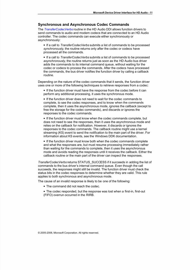
Synchronous and Asynchronous Codec Commands
The TransferCodecVerbs routine in the HD Audio DDI allows function drivers tosend commands to audio and modem codecs that are connected to an HD Audiocontroller. The codec commands can execute either synchronously or asynchronously:
• If a call to TransferCodecVerbs submits a list of commands to be processedsynchronously , the routine returns only after the codec or codecs haveprocessed all the commands.
• If a call to TransferCodecVerbs submits a list of commands to be processedasynchronously , the routine returns just as soon as the HD Audio bus driver adds the commands to its internal command queue, without waiting for thecodec or codecs to process the commands. After the codecs have processedthe commands, the bus driver notifies the function driver by calling a callbackroutine.
Depending on the nature of the codec commands that it sends, the function driver uses one or more of the following techniques to retrieve responses from a codec:
• If the function driver must have the response from the codec before it can
perform any additional processing, it uses the synchronous mode.• If the function driver does not need to wait for the codec commands tocomplete, to see the codec responses, and to know when the commandscomplete, then it uses the asynchronous mode, ignores the callback (except tofree the storage for the codec commands), and discards or ignores theresponses to the codec commands.
• If the function driver must know when the codec commands complete, butdoes not need to see the responses, then it uses the asynchronous mode andrelies on the callback for notification. However, it discards or ignores theresponses to the codec commands. The callback routine might use a kernelstreaming (KS) event to send the notification to the main part of the driver. For information about KS events, see the Windows DDK documentation.
•If the function driver must know both when the codec commands complete
and what the responses are, but must resume processing immediately rather than waiting for the commands to complete, then it uses the asynchronousmode and avoids reading the responses until it receives the callback. Either thecallback routine or the main part of the driver can inspect the responses.
TransferCodecVerbs returns STATUS_SUCCESS if it succeeds in adding the list of commands to the bus driver’s internal command queue. Even though the callsucceeds, the responses might still be invalid. The function driver must check thestatus bits in the codec responses to determine whether they are valid. This ruleapplies to both synchronous and asynchronous mode.
The cause of an invalid response is likely to be one of the following:
• The command did not reach the codec.
• The codec responded, but the response was lost when a first-in, first-out(FIFO) overrun occurred in the RIRB.
© 2005-2006, Microsoft Corporation. All rights reserved.

8/8/2019 HDAudioDdi11
http://slidepdf.com/reader/full/hdaudioddi11 12/69
Microsoft Device Driver Interface for HD Audio - 12
The latter problem indicates that the RIRB FIFO is of insufficient size.
Each codec response contains an IsValid flag to indicate whether the response isvalid and a HasFifoOverrun flag to indicate whether a RIRB FIFO overrun hasoccurred. If IsValid=0, indicating that a response is invalid, the HasFifoOverrunflag helps to identify the source of the failure:
• If HasFifoOverrun=0, then the codec failed to respond within the required
time interval. The probable cause is that the command never reached thecodec.
• If HasFifoOverrun=1, then the command probably reached the codec, butthe response was lost due to a FIFO overrun.
During a call to TransferCodecCommands, the caller provides a pointer to an arrayof HDAUDIO_CODEC_TRANSFER structures. Each structure contains a commandand provides space for a response. The bus driver always writes each responseinto the structure that contains the command that triggered the response.
For each call to TransferCodecCommands, the order in which the commands areprocessed is determined by the order of the commands in the array. Processing of the first command in the array always completes before processing of the second
command begins, and so on.
In addition, if a client makes an asynchronous call to TransferCodecCommands andthen calls TransferCodecCommands a second time without waiting for the callbackfrom the first call, the relative order in which the two groups of commands from thetwo calls are processed is defined by the order in which the client submitted the twogroups of commands. Thus, the bus driver processes all the commands from thefirst call before it begins processing the commands from the second call.
However, the relative order of commands sent by two different function driver instances is undefined. (Each instance has its own physical device object.) For example, if instance 1 calls TransferCodecCommands to send commands A, B, andC in the order A-B-C, and instance 2 calls TransferCodecCommands to sendcommands X, Y, and Z in the order X-Y-Z, then the bus driver might execute the
commands in the order A-X-Y-B-Z-C.
When separate function driver threads share access to the same set of hardwareresources, the relative order of commands from different driver threads might beimportant. If so, the function driver is responsible for synchronizing the sharing of the resources among the threads.
For example, the hardware interface for writing a sequence of data bytes to a codecmight consist of an index register and an 8-bit data register. First, the function driver submits a codec command to load the starting index into the index register. Next,the driver submits a command to write the first byte of data to the data register. Theindex register increments following each successive write to the data register untilthe transfer is complete. However, if two driver threads fail to properly synchronizetheir accesses of the index and data registers, the relative order of the individual
register accesses by the two threads is undefined and the probable result is datacorruption or an invalid hardware configuration.
The TransferCodecVerbs routine is available in both versions of the HD Audio DDI.
Wall Clock and Link Position Registers
The HD Audio controller contains a 32-bit wall clock counter register thatincrements at the bit-clock rate of the HD Audio Link and rolls over approximatelyevery 89 seconds. Software uses this counter to synchronize between two or more
© 2005-2006, Microsoft Corporation. All rights reserved.

8/8/2019 HDAudioDdi11
http://slidepdf.com/reader/full/hdaudioddi11 13/69
Microsoft Device Driver Interface for HD Audio - 13
controller devices by measuring the relative drift between the devices’ hardwareclocks.
In addition, the HD Audio controller contains a set of link position registers. EachDMA engine has a link position register that indicates the current read or writeposition of the data that the engine is transmitting over the HD Audio Link. Theposition register expresses the current position as a byte offset from the beginning
of the cyclic buffer:
• In a render stream, the link position register indicates the cyclic buffer offsetof the next byte that the DMA engine will send over the link to the codec.
• In a capture stream, the link position register indicates the cyclic buffer offsetof the next byte that the DMA engine will receive from the codec over the link.
The cyclic buffer offset is simply the offset in bytes of the current read or writeposition from the start of the cyclic buffer. Upon reaching the end of the buffer, theposition wraps around to the start of the buffer and the cyclic buffer offset resets tozero. The cyclic buffer resides in system memory. For more information, see theIntel High Definition Audio Specification.
A kernel-mode function driver can read the wall clock and link position registersdirectly. To enable direct access, the HD Audio bus driver maps the physicalmemory that contains the registers into system virtual memory. The function driver calls the GetWallClockRegister or GetLinkPositionRegister routine to obtain asystem virtual address pointer to the wall clock register or a link position register.These two routines are available in both versions of the HD Audio DDI.
The HD Audio controller hardware mirrors the wall clock and link position registersinto memory pages that do not contain any of the other registers in the controller.Thus, if the function driver maps the mirrored wall clock or position registers to user mode, no user-mode programs can access any of the controller’s other registers.The driver never allows a user-mode program to touch these other registers andprogram the hardware.
Register mirroring must accommodate the host processor’s page size. Dependingon the host processor architecture, a typical page size might be 4,096 or 8,192bytes.
Hardware Resource Management
Through the HD Audio DDI, function drivers for audio and modem codecs canallocate and free hardware resources in the HD Audio controller device. Theseresources are chiefly:
• DMA engines in the HD Audio controller.
• Bus bandwidth on the HD Audio Link.
Allocating DMA Engines
The HD Audio controller contains a fixed number of DMA engines. Each engine canperform scatter-gather transfers for a single render or capture stream.
Three types of DMA engines are available:
• Render DMA engines, which can handle only render streams.
• Capture DMA engines, which can handle only capture streams.
• Bidirectional DMA engines, which can be configured to handle either render or capture streams.
© 2005-2006, Microsoft Corporation. All rights reserved.

8/8/2019 HDAudioDdi11
http://slidepdf.com/reader/full/hdaudioddi11 14/69
Microsoft Device Driver Interface for HD Audio - 14
When allocating a DMA engine for a render stream, the AllocateCaptureDmaEngine routine allocates a render DMA engine if one isavailable. If the supply of render DMA engines is exhausted, the routine allocates abidirectional DMA engine if one is available.
Similarly, when allocating a DMA engine for a capture stream, the AllocateRenderDmaEngine AllocateRenderDmaEngine routine allocates a capture
DMA engine if one is available. If the supply of capture DMA engines is exhausted,the routine allocates a bidirectional DMA engine if one is available.
The AllocateXxxDmaEngine routines are available in both versions of the HD AudioDDI.
Allocating Link Bandwidth
The HD Audio Link has a finite amount of bus bandwidth available for render andcapture streams to use. To ensure glitchless audio, the HD Audio bus driver manages bus bandwidth as a shared resource. When a function driver allocates aDMA engine, it must also allocate a portion of the available bus bandwidth for theDMA engine’s render or capture stream to use.
A fixed amount of bus bandwidth is available on the HD Audio Link’s serial data in(SDI) lines and on the serial data out (SDO) lines. The HD Audio bus driver monitors bandwidth consumption separately on the SDI and SDO lines. If a requestto allocate input or output bus bandwidth exceeds the available bandwidth, the busdriver fails the request.
When the function driver calls the bus driver’s AllocateCaptureDmaEngine and AllocateRenderDmaEngine routine, it specifies a stream format. The stream formatspecifies the stream’s sample rate, sample size, and number of channels. From thisinformation, the AllocateXxxDmaEngine routine determines the stream’s busbandwidth requirements. If sufficient bandwidth is available, the routine allocatesthe required bandwidth for the DMA engine to use. Otherwise, the call to
AllocateXxxDmaEngine fails.
A function driver can call ChangeBandwidthAllocation to request a change in thebandwidth allocation for an existing DMA engine allocation.
The AllocateXxxDmaEngine and ChangeBandwidthAllocation routines are availablein both versions of the HD Audio DDI.
Striping
The HD Audio architecture supports a technique called striping that can reduce theamount of bus bandwidth that render streams consume. If the HD Audio hardwareinterface provides more than one SDO line, striping can increase the rate at which arender DMA engine can transfer data by alternately distributing the bits in the datastream among the SDO lines. The first bit (the most significant bit) travels over SDO0, the second bit travels over SDO1, and so on. For example, with two SDOlines, striping effectively doubles the transfer rate by splitting the stream betweenthe two SDO lines. A DMA engine that uses striping to transfer a render streamover two SDO lines consumes only half the bus bandwidth that it would consume if it did not use striping.
The function driver enables striping through the AllocateRenderDmaEngine routine’s stripe call parameter.
For more information about striping, see the Intel High Definition AudioSpecification.
© 2005-2006, Microsoft Corporation. All rights reserved.

8/8/2019 HDAudioDdi11
http://slidepdf.com/reader/full/hdaudioddi11 15/69
Microsoft Device Driver Interface for HD Audio - 15
Synchronizing Two or More Streams
The SetDmaEngineState routine sets the state of one or more DMA engines to oneof the following: running , paused , stopped , or reset . If a call to this routine specifiesmore than one DMA engine, then all the DMA engines make the state transitionsynchronously.
The ability to synchronize a group of streams is required for some audioapplications. For example, an audio driver might use codec-combining to create alogical surround-sound audio device that joins two audio codecs: one codec drivesthe front speakers and a second audio codec drives the back speakers. Dependingon the capabilities of the codecs, the audio driver might be required to split theoriginal surround-sound audio stream into two streams, one for each codec. Byusing the SetDmaEngineState routine to start and stop the streams in unison, thetwo streams can remain synchronized.
Allowing the two streams to fall out of synchronization by even a few samples mightcause undesirable audio artifacts.
The SetDmaEngineState routine is available in both versions of the HD Audio DDI.
The UAA class driver does not perform codec-combining.
Wake Enable
Before powering down a codec, the codec function driver typically enables thecodec to wake up the system if a status-change event occurs while the codec is inthe powered-down state. For an audio codec, such an event can be triggered whenthe user inserts a plug into an input jack or removes a plug from a jack. For amodem codec, a status-change event can occur when the phone rings to indicatean incoming call. For more information about status-change events, see the Intel High Definition Audio Specification.
To prepare for powering down, the function driver first configures the codec tosignal the HD Audio bus controller when a status-change event occurs. Next, thefunction driver sends an IRP_MN_WAIT_WAKE power-management input/outputrequest packet (IRP) to the HD Audio bus driver to tell it to enable the wake-upsignal from the codec. Later, if the wake-up signal is enabled and the codectransmits a status-change event over the codec's SDI line, the controller generatesa wake-up signal to the system and the bus driver notifies the function driver bycompleting the IRP_MN_WAIT_WAKE IRP. For information aboutIRP_MN_WAIT_WAKE, see the Windows DDK documentation.
Following a wake event, the bus driver determines which codec generated thewake-up signal and completes any pending IRP_MN_WAIT_WAKE IRPs on thatcodec. However, if the codec contains both audio and modem function groups, for example, the bus driver has no way to determine which function group is the sourceof the wake-up signal. In this case, the function driver must send its own queries tothe codec to verify the source of the wake-up signal.
Data Copying and Caching Policy
The sample HD Audio codec function driver in the HD Audio IHV-Enabling Kit isimplemented as an adapter driver that interfaces to the PortCls system driver. As aPortCls adapter driver, the function driver models the subdevices in the audio codecas wave filters and topology filters, and it implements WaveCyclic and Topologyminiport drivers to support these subdevices.
© 2005-2006, Microsoft Corporation. All rights reserved.

8/8/2019 HDAudioDdi11
http://slidepdf.com/reader/full/hdaudioddi11 16/69
Microsoft Device Driver Interface for HD Audio - 16
As explained in the Windows DDK documentation, a WaveCyclic miniport driver copies audio data between the DMA buffer, which the HD Audio controller hardwareaccesses, and the client buffer, which the user-mode audio application accesses:
• For a playback data stream, the driver copies data from the client buffer to theDMA buffer.
• For a capture data stream, the driver copies data from the DMA buffer to theclient buffer.
For both playback and capture streams, the driver can achieve the bestperformance by enabling caching of the DMA buffer memory (cache typeMmCached) and relying on the PCI controller's bus-snooping mechanism to ensurecache coherency. However, some PCI Express controller implementations do notsnoop the HD Audio controller's isochronous data transfers (for example, Intel'sinitial PCI Express chip set).
The function driver cannot detect whether the PCI controller hardware supportssnooping of DMA buffer transfers or performs isochronous data transfers. To avoidpotential cache coherency problems, the driver disables caching of the DMA buffer memory by specifying the caching type for that memory as MmWriteCombined.
(MmNonCached would also work, but might not perform as well.) If you write acustom adapter driver that is based on the sample function driver, your WaveCyclicminiport driver should behave similarly unless you can verify that the PCI controller does in fact support snooping of DMA buffer transfers.
The sample HD Audio function driver uses the HDAUDIO_BUS_INTERFACEversion of the HD Audio DDI. The function driver calls the AllocateDmaBuffer routine to allocate the memory for the DMA buffer. Next, it calls theMmMapLockedPagesSpecifyCacheroutine to map the physical pages in theDMA buffer. During this call, the function driver specifies the cache type asMmWriteCombined. For information about MmMapLockedPagesSpecifyCache,see the Windows DDK documentation.
To support devices and systems that do not perform bus snooping, a custom
function driver must follow these rules:• For a playback stream, specify the DMA buffer's cache type asMmWriteCombined. After copying a block of data from the client buffer to theDMA buffer, call the KeMemoryBarrier function to make the data visible to theDMA engine. KeMemoryBarrier flushes the copied data to memory in anefficient way that leaves the processor's data caches largely undisturbed.
• For a capture stream, specify the DMA buffer's cache type as either MmWriteCombined or MmNonCached. In addition, the function driver shouldavoid writing to the DMA buffer. If it must perform in-place processing of audiosamples, it should first copy the data elsewhere.
For more information about KeMemoryBarrier , see the Windows DDKdocumentation.
The block of data that the function driver copies to or from the DMA buffer is not required to begin or end on a write-combining buffer boundary, and its size is not required to be a multiple of the write-combining buffer size (typically, 32 or 64bytes).
For codec function drivers using the HDAUDIO_BUS_INTERFACE_V2 version of the DDI, the AllocateDmaBufferWithNotification routine performs the same as the
AllocateDmaBuffer routine with the exception that it sets up and enables IOCinterrupts.
© 2005-2006, Microsoft Corporation. All rights reserved.

8/8/2019 HDAudioDdi11
http://slidepdf.com/reader/full/hdaudioddi11 17/69
Microsoft Device Driver Interface for HD Audio - 17
For codec function drivers that use the HDAUDIO_BUS_INTERFACE_BDL versionof the DDI, the AllocateContiguousDmaBuffer routine performs both theallocation and mapping of the DMA buffer memory. The routine always sets thebuffer's cache type to MmWriteCombined.
For more information about write-combining, see the IA-32 Intel ArchitectureSoftware Developer’s Manual at http://www.intel.com.
Using DMA Interrupt Driven Event Notifications
Support for DMA interrupt driven event notifications are provided via theHDAUDIO_BUS_INTERFACE_V2 version of the HD Audio DDI. There are four routines that facilitate this support: AllocateDmaBufferWithNotification, FreeDmaBufferWithNotification, RegisterNotificationEvent , andUnregisterNotificationEvent .
To utilize this capability, the codec function driver uses AllocateDmaBufferWithNotification to allocate its audio buffer. This routineallocates the audio buffer, allocates and initializes the BDL, and programs the DMAengine to use the buffer, the BDL, and to generate IOC interrupts.
If AllocateDmaBufferWithNotification is called requesting a notification count of 1,the engine is programmed to generate an interrupt upon completion of the last entryin the BDL (i.e. – the end of the buffer). If AllocateDmaBufferWithNotification iscalled requesting a notification count of 2, the buffer is allocated and the BDLinitialized such that an interrupt is generated at the mid-point of the buffer and at theend of the buffer.
Once the buffer is allocated with AllocateDmaBufferWithNotification, the client canregister events that will be notified (signaled) using the RegisterNotificationEvent routine. The client can register more than one event by making multiple calls toRegisterNotificationEvent and passing pointers to different events.
The HD Audio bus driver, when it receives an IOC interrupt for a DMA engine withevent notification enables, queues a DPC (deferred procedure call). When the DPC
runs it walks the list of notification events maintained by the HD Audio bus driver and signals each event.
By utilizing the WaveRT Port/Miniport APIs and property sets as described in theWaveRT white paper and Windows DDK documentation, direct signaling of user-mode events can be facilitated to enable DMA driven notification/scheduling in auser-mode audio client.
The codec function driver removes an event from the list maintained by theHD Audio bus driver using the UnregisterNotificationEvent routine. The codecfunction driver needs to unregister each registered event prior to freeing the audiobuffer. To free an audio buffer allocated with AllocateDmaBufferWithNotification,the FreeDmaBufferWithNotification routine must be used.
Querying for an HD Audio DDITo obtain a counted reference to an object with an, the function driver for an audioor modem codec sends an IRP_MN_QUERY_INTERFACE input/output control(IOCTL) to the HD Audio bus driver. For information about this IOCTL, see theWindows DDK documentation.
In Windows Vista and later, the HD Audio bus driver supports only theHDAUDIO_BUS_INTERFACE and HDAUDIO_BUS_INTERFACE_V2 versions of the DDI. It does not support the HDAUDIO_BUS_INTERFACE_BDL version.
© 2005-2006, Microsoft Corporation. All rights reserved.
8/8/2019 HDAudioDdi11
http://slidepdf.com/reader/full/hdaudioddi11 18/69
Microsoft Device Driver Interface for HD Audio - 18
An HD Audio bus driver can be installed as an upgrade in Windows 2000,Windows XP, and Windows Server 2003. This bus driver supports both DDIversions.
The procedures for obtaining references to the HDAUDIO_BUS_INTERFACE,HDAUDIO_BUS_INTERFACE_V2 and HDAUDIO_BUS_INTERFACE_BDLversions of the DDI are described in “Obtaining an HDAUDIO_BUS_INTERFACE
DDI Object”, “Obtaining an HDAUDIO_BUS_INTERFACE_V2 DDI Object” and“Obtaining an HDAUDIO_BUS_INTERFACE_BDL DDI Object.”
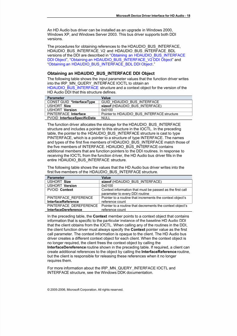
Obtaining an HDAUDIO_BUS_INTERFACE DDI Object
The following table shows the input parameter values that the function driver writesinto the IRP_MN_QUERY_INTERFACE IOCTL to obtain anHDAUDIO_BUS_INTERFACE structure and a context object for the version of theHD Audio DDI that this structure defines.
Parameter ValueCONST GUID *InterfaceType GUID_HDAUDIO_BUS_INTERFACEUSHORT Size sizeof (HDAUDIO_BUS_INTERFACE)USHORT Version 0x0100PINTERFACE Interface Pointer to HDAUDIO_BUS_INTERFACE structure
PVOID InterfaceSpecificData NULL
The function driver allocates the storage for the HDAUDIO_BUS_INTERFACEstructure and includes a pointer to this structure in the IOCTL. In the precedingtable, the pointer to the HDAUDIO_BUS_INTERFACE structure is cast to typePINTERFACE, which is a pointer to a structure of type INTERFACE. The namesand types of the first five members of HDAUDIO_BUS_INTERFACE match those of the five members of INTERFACE. HDAUDIO_BUS_INTERFACE containsadditional members that are function pointers to the DDI routines. In response toreceiving the IOCTL from the function driver, the HD Audio bus driver fills in theentire HDAUDIO_BUS_INTERFACE structure.
The following table shows the values that the HD Audio bus driver writes into thefirst five members of the HDAUDIO_BUS_INTERFACE structure.
Parameter ValueUSHORT Size sizeof (HDAUDIO_BUS_INTERFACE)USHORT Version 0x0100PVOID Context Context information that must be passed as the first call
parameter to every DDI routinePINTERFACE_REFERENCEInterfaceReference
Pointer to a routine that increments the context object’sreference count
PINTERFACE_DEREFERENCEInterfaceDereference
Pointer to a routine that decrements the context object’sreference count
In the preceding table, the Context member points to a context object that containsinformation that is specific to the particular instance of the baseline HD Audio DDIthat the client obtains from the IOCTL. When calling any of the routines in the DDI,the client function driver must always specify the Context pointer value as the first
call parameter. The context information is opaque to the client. The HD Audio busdriver creates a different context object for each client. When the context object isno longer required, the client frees the context object by calling theInterfaceDereference routine shown in the preceding table. If required, a client cancreate additional references to the object by calling the InterfaceReference routine,but the client is responsible for releasing these references when it no longer requires them.
For more information about the IRP_MN_QUERY_INTERFACE IOCTL andINTERFACE structure, see the Windows DDK documentation.
© 2005-2006, Microsoft Corporation. All rights reserved.

8/8/2019 HDAudioDdi11
http://slidepdf.com/reader/full/hdaudioddi11 19/69
Microsoft Device Driver Interface for HD Audio - 19
Obtaining an HDAUDIO_BUS_INTERFACE_V2 DDI Object
The following table shows the input parameter values that the function driver writesinto the IRP_MN_QUERY_INTERFACE IOCTL to obtain anHDAUDIO_BUS_INTERFACE _V2 structure and a context object for the version of the HD Audio DDI that this structure defines.
Parameter Value
CONST GUID *InterfaceType GUID_HDAUDIO_BUS_INTERFACE_V2USHORT Size sizeof (HDAUDIO_BUS_INTERFACE_V2)USHORT Version 0x0100PINTERFACE Interface Pointer to HDAUDIO_BUS_INTERFACE_V2 structurePVOID InterfaceSpecificData NULL
The function driver allocates the storage for the HDAUDIO_BUS_INTERFACE_V2structure and includes a pointer to this structure in the IOCTL. In the precedingtable, the pointer to the HDAUDIO_BUS_INTERFACE_V2 structure is cast to typePINTERFACE, which is a pointer to a structure of type INTERFACE. The namesand types of the first five members of HDAUDIO_BUS_INTERFACE_V2 matchthose of the five members of INTERFACE. HDAUDIO_BUS_INTERFACE_V2contains additional members that are function pointers to the DDI routines. Inresponse to receiving the IOCTL from the function driver, the HD Audio bus driver
fills in the entire HDAUDIO_BUS_INTERFACE_V2 structure.
The following table shows the values that the HD Audio bus driver writes into thefirst five members of the HDAUDIO_BUS_INTERFACE_V2 structure.
Parameter ValueUSHORT Size sizeof (HDAUDIO_BUS_INTERFACE_V2)USHORT Version 0x0100PVOID Context Context information that must be passed as the first call
parameter to every DDI routinePINTERFACE_REFERENCEInterfaceReference
Pointer to a routine that increments the context object’sreference count
PINTERFACE_DEREFERENCEInterfaceDereference
Pointer to a routine that decrements the context object’sreference count
In the preceding table, the Context member points to a context object that contains
information that is specific to the particular instance of the baseline HD Audio DDIthat the client obtains from the IOCTL. When calling any of the routines in the DDI,the client function driver must always specify the Context pointer value as the firstcall parameter. The context information is opaque to the client. The HD Audio busdriver creates a different context object for each client. When the context object isno longer required, the client frees the context object by calling theInterfaceDereference routine shown in the preceding table. If required, a client cancreate additional references to the object by calling the InterfaceReference routine,but the client is responsible for releasing these references when it no longer requires them.
For more information about the IRP_MN_QUERY_INTERFACE IOCTL andINTERFACE structure, see the Windows DDK documentation.
Obtaining an HDAUDIO_BUS_INTERFACE_BDL DDI Object
As explained previously, the function driver for an audio or modem codec obtains acounted reference to an object with an HD Audio DDI by sending anIRP_MN_QUERY_INTERFACE IOCTL to the HD Audio bus driver.
© 2005-2006, Microsoft Corporation. All rights reserved.

8/8/2019 HDAudioDdi11
http://slidepdf.com/reader/full/hdaudioddi11 20/69
Microsoft Device Driver Interface for HD Audio - 20
The following table shows the input parameter values that the function driver writesinto the IOCTL to obtain an HDAUDIO_BUS_INTERFACE_BDL structure and acontext object for the version of the HD Audio DDI that this structure defines.
Parameter ValueCONST GUID *InterfaceType GUID_HDAUDIO_BUS_INTERFACE_BDLUSHORT Size sizeof (HDAUDIO_BUS_INTERFACE_BDL)USHORT Version 0x0100PINTERFACE Interface Pointer to HDAUDIO_BUS_INTERFACE_BDL structurePVOID InterfaceSpecificData NULL
The function driver allocates the storage for the HDAUDIO_BUS_INTERFACE_BDLstructure and includes a pointer to this structure in the IOCTL. In the precedingtable, the pointer to the HDAUDIO_BUS_INTERFACE_BDL structure is cast to typePINTERFACE, which is a pointer to a structure of type INTERFACE. The namesand types of the first five members of HDAUDIO_BUS_INTERFACE_BDL matchthose of the five members of INTERFACE. HDAUDIO_BUS_INTERFACE_BDLcontains additional members that are function pointers to the DDI routines. Inresponse to receiving the IOCTL from the function driver, the HD Audio bus driver fills in the entire HDAUDIO_BUS_INTERFACE_BDL structure.
The following table shows the values that the HD Audio bus driver writes into the
first five members of the HDAUDIO_BUS_INTERFACE_BDL structure.
Parameter ValueUSHORT Size sizeof (HDAUDIO_BUS_INTERFACE_BDL)USHORT Version 0x0100PVOID Context Context information that needs to be passed as the first
call parameter to every DDI routinePINTERFACE_REFERENCEInterfaceReference
Pointer to a routine that increments the context object’sreference count
PINTERFACE_DEREFERENCEInterfaceDereference
Pointer to a routine that decrements the context object’sreference count
In the preceding table, the Context member points to a context object that containsinformation that is specific to the particular instance of theHDAUDIO_BUS_INTERFACE_BDL version of the DDI that the client obtains from
the IOCTL. As explained previously, when calling any of the routines in the DDI, theclient function driver must always specify the Context pointer value as the first callparameter.
For more information about the IRP_MN_QUERY_INTERFACE IOCTL andINTERFACE structure, see the Windows DDK documentation.
Technical Reference
This section is a technical reference that describes the routines in the two versionsof the HD Audio DDI that the HDAUDIO_BUS_INTERFACE andHDAUDIO_BUS_INTERFACE_BDL structures define. It also describes the types of structures that these routines use as parameters.
Two sets of reference pages are presented: DDI Routines and Structure Types.
DDI Routines
As explained in “Differences between the Two DDI Versions,” two versions of theHD Audio DDI exist. These two DDI versions are defined by theHDAUDIO_BUS_INTERFACE and HDAUDIO_BUS_INTERFACE_BDL structures.
Both DDI versions are accessible only in kernel mode.
© 2005-2006, Microsoft Corporation. All rights reserved.

8/8/2019 HDAudioDdi11
http://slidepdf.com/reader/full/hdaudioddi11 21/69
Microsoft Device Driver Interface for HD Audio - 21
Either DDI version provides access to the hardware resources that the HD Audiobus controller manages. These resources include codecs, DMA engines, linkbandwidth, link position registers, and a wall clock register. The HD Audio busdriver implements the DDI and exposes the DDI to its children. The children areinstances of kernel-mode function drivers that use the DDI to manage the hardwarecodecs that are connected to the HD Audio controller.
To obtain access to either DDI version, a function driver must query the HD Audiobus driver for a DDI context object. For more information, see “Obtaining anHDAUDIO_BUS_INTERFACE DDI Object” , “Obtaining anHDAUDIO_BUS_INTERFACE_V2 DDI Object”, and “Obtaining anHDAUDIO_BUS_INTERFACE_BDL DDI Object.”
Every routine in either DDI version takes a pointer to the context object as its firstcall parameter.
The HDAUDIO_BUS_INTERFACE structure defines a DDI that contains thefollowing routines:
AllocateCaptureDmaEngine AllocateDmaBuffer
AllocateRenderDmaEngineChangeBandwidthAllocationFreeDmaBuffer FreeDmaEngineGetDeviceInformationGetLinkPositionRegister GetResourceInformationGetWallClockRegister RegisterEventCallback SetDmaEngineStateTransferCodecVerbsUnregisterEventCallback
The HDAUDIO_BUS_INTERFACE version of the HD Audio DDI is supported in
Windows Vista and later. In addition, a version of the HD Audio bus driver thatsupports this DDI can be installed in Windows 2000, Windows XP, andWindows Server 2003.
The HDAUDIO_BUS_INTERFACE_V2 structure defines a DDI that contains thefollowing routines:
AllocateCaptureDmaEngine AllocateDmaBuffer AllocateRenderDmaEngineChangeBandwidthAllocationFreeDmaBuffer FreeDmaEngineGetDeviceInformation
GetLinkPositionRegister GetResourceInformationGetWallClockRegister RegisterEventCallback SetDmaEngineStateTransferCodecVerbsUnregisterEventCallback
AllocateDmaBufferWithNotificationFreeDmaBufferWithNotification
© 2005-2006, Microsoft Corporation. All rights reserved.

8/8/2019 HDAudioDdi11
http://slidepdf.com/reader/full/hdaudioddi11 22/69
Microsoft Device Driver Interface for HD Audio - 22
RegisterNotificationEvent UnregisterNotificationEvent
The HDAUDIO_BUS_INTERFACE_V2 version of the HD Audio DDI is supported inWindows Vista and later.
The HDAUDIO_BUS_INTERFACE_BDL structure defines a DDI that contains thefollowing routines:
AllocateCaptureDmaEngine AllocateContiguousDmaBuffer AllocateRenderDmaEngineChangeBandwidthAllocationFreeContiguousDmaBuffer FreeDmaEngineGetDeviceInformationGetLinkPositionRegister GetResourceInformationGetWallClockRegister RegisterEventCallback
SetDmaEngineStateSetupDmaEngineWithBdl TransferCodecVerbsUnregisterEventCallback
A version of the HD Audio bus driver that supports theHDAUDIO_BUS_INTERFACE_BDL version of the HD Audio DDI can be installed inWindows 2000, Windows XP, and Windows Server 2003. However, Windows Vistaprovides no support for this DDI version.
Most of the routines in the DDIs are identical in both name and operation. However,the following two routines, which are part of the HDAUDIO_BUS_INTERFACE andHDAUDIO_BUS_INTERFACE_V2 versions of the DDI, are not included in the
HDAUDIO_BUS_INTERFACE_BDL version: AllocateDmaBuffer FreeDmaBuffer
Additionally, the following four routines in the HDAUDIO_BUS_INTERFACE_V2version of the DDI are not part of the HDAUDIO_BUS_INTERFACE andHDAUDIO_BUS_INTERFACE_BDL versions:
AllocateDmaBufferWithNotificationFreeDmaBufferWithNotificationRegisterNotificationEvent UnregisterNotificationEvent
Finally, the following three routines in the HDAUDIO_BUS_INTERFACE_BDLversion of the DDI are not part of the HDAUDIO_BUS_INTERFACE and
HDAUDIO_BUS_INTERFACE_V2 versions: AllocateContiguousDmaBuffer FreeContiguousDmaBuffer SetupDmaEngineWithBdl
This section describes the following DDI routines:
AllocateCaptureDmaEngine AllocateContiguousDmaBuffer AllocateDmaBuffer
© 2005-2006, Microsoft Corporation. All rights reserved.

8/8/2019 HDAudioDdi11
http://slidepdf.com/reader/full/hdaudioddi11 23/69
Microsoft Device Driver Interface for HD Audio - 23
AllocateDmaBufferWithNotification AllocateRenderDmaEngineChangeBandwidthAllocationFreeContiguousDmaBuffer FreeDmaBuffer FreeDmaBufferWithNotificationFreeDmaEngineGetDeviceInformationGetLinkPositionRegister GetResourceInformationGetWallClockRegister RegisterEventCallback RegisterNotificationEvent SetDmaEngineStateSetupDmaEngineWithBdl TransferCodecVerbsUnregisterEventCallback UnregisterNotificationEvent
The preceding list contains all the routines that appear in any of the versions of the
DDI.
AllocateCaptureDmaEngine
The AllocateCaptureDmaEngine routine allocates a DMA engine for a capturestream.
The function pointer type for an AllocateCaptureDmaEngine routine is definedas:
typedef NTSTATUS(*PALLOCATE_CAPTURE_DMA_ENGINE)(
IN PVOID context,IN UCHAR codecAddress,
IN PHDAUDIO_STREAM_FORMAT streamFormat,OUT HANDLE *handle,OUT PHDAUDIO_CONVERTER_FORMAT converterFormat);
Parameterscontext
Specifies the context value from the Context member of theHDAUDIO_BUS_INTERFACE or HDAUDIO_BUS_INTERFACE_BDL structure.
codecAddressSpecifies a codec address. This parameter identifies the SDI line on whichthe codec supplies the capture data to the HD Audio bus controller. A bus
controller with n SDI pins can support up to n codecs with addressesranging from 0 to n-1.
streamFormat Specifies the requested stream format. This parameter points to a caller-allocated structure of type HDAUDIO_STREAM_FORMAT that specifies adata format for the stream.
© 2005-2006, Microsoft Corporation. All rights reserved.

8/8/2019 HDAudioDdi11
http://slidepdf.com/reader/full/hdaudioddi11 24/69
Microsoft Device Driver Interface for HD Audio - 24
handleRetrieves the handle to the DMA engine. This parameter points to a caller-allocated HANDLE variable into which the routine writes a handle thatidentifies the DMA engine.
converterFormat Retrieves the converter format. This parameter points to a caller-allocated
structure of type HDAUDIO_CONVERTER_FORMAT into which the routinewrites the encoded format.
Return Value AllocateCaptureDmaEngine returns STATUS_SUCCESS if the call succeeds inreserving a DMA engine. Otherwise, the routine returns an appropriate error code. The following table shows some of the possible return status codes.
Error code DescriptionSTATUS_BUFFER_TOO_SMALL Indicates that the DMA engine is unable to
allocate sufficient internal FIFO storage tosupport the requested stream format.
STATUS_INSUFFICIENT_RESOURCES Indicates that either no DMA engine isavailable or the request exceeds theavailable bandwidth resources.
STATUS_INVALID_PARAMETER Indicates that one of the parameter valuesis incorrect (invalid parameter value or badpointer).
HeadersDeclared in hdaudio.h. Include hdaudio.h.
CommentsThis routine allocates a capture DMA engine and specifies the data format for the stream. If successful, the routine outputs a handle that the caller subsequently uses to identify the DMA engine.
The AllocateCaptureDmaEngine routine reserves hardware resources (theDMA engine) but does not configure the DMA hardware. After calling this
routine to reserve a DMA engine, a function driver must assign a DMA buffer tothe DMA engine and configure the engine to use the buffer:
• If using the HDAUDIO_BUS_INTERFACE version of the HD AudioDDI, the function driver calls the AllocateDmaBuffer routine to have theHD Audio bus driver allocate a data buffer for DMA transfers and set up theDMA engine to use the buffer.
• If using the HDAUDIO_BUS_INTERFACE_BDL version of the DDI,the function driver calls AllocateContiguousDmaBuffer to allocate the DMAbuffer and calls the SetupDmaEngineWithBdl routine to set up the DMAengine to use the buffer.
The streamFormat parameter specifies the data format for the capture stream.
Following the call to AllocateCaptureDmaEngine, the stream’s format can bechanged by calling ChangeBandwidthAllocation.
Through the handle parameter, the routine outputs a handle that the caller usesto identify the allocated DMA engine in subsequent calls to AllocateDmaBuffer ,ChangeBandwidthAllocation, FreeDmaBuffer , SetupDmaEngineWithBdl , andSetDmaEngineState. The function driver frees the handle by callingFreeDmaEngine.
Through the converterFormat parameter, the routine outputs a streamdescriptor value that the caller can use to program the input converters. The
© 2005-2006, Microsoft Corporation. All rights reserved.

8/8/2019 HDAudioDdi11
http://slidepdf.com/reader/full/hdaudioddi11 25/69
Microsoft Device Driver Interface for HD Audio - 25
routine encodes the information from the streamFormat parameter into a 16-bitinteger. For more information, see HDAUDIO_CONVERTER_FORMAT.
Immediately following a successful call to AllocateCaptureDmaEngine, the DMAengine is in the reset stream state. Before calling SetDmaEngineState tochange the DMA engine to the running , paused , or stopped state, the clientmust first allocate a DMA buffer for the engine.
A Windows Driver Model (WDM) audio driver calls AllocateCaptureDmaEngineat pin-creation time during execution of its NewStream method (for example,see the description of IMiniportWavePci::NewStream in the Windows DDKdocumentation).
Callers of AllocateCaptureDmaEngine must be running atIRQL PASSIVE_LEVEL.
See AlsoHDAUDIO_BUS_INTERFACE, HDAUDIO_BUS_INTERFACE_BDL,HDAUDIO_STREAM_FORMAT, HDAUDIO_CONVERTER_FORMAT,
AllocateDmaBuffer , AllocateContiguousDmaBuffer , SetupDmaEngineWithBdl , ChangeBandwidthReservation, SetDmaEngineState, FreeDmaEngine
AllocateContiguousDmaBuffer
The AllocateContiguousDmaBuffer routine allocates a DMA buffer that consistsof a single, contiguous block of physical memory.
The function pointer type for an AllocateContiguousDmaBuffer routine isdefined as:
typedef NTSTATUS(*PALLOCATE_CONTIGUOUS_DMA_BUFFER)(
IN PVOID context,IN HANDLE handle,ULONG requestedBufferSize,OUT PVOID *dataBuffer,
OUT PHDAUDIO_BUFFER_DESCRIPTOR *bdl);
Parameterscontext
Specifies the context value from the Context member of theHDAUDIO_BUS_INTERFACE_BDL structure.
handleHandle identifying the DMA engine. This handle value was obtained from aprevious call to AllocateCaptureDmaEngine or AllocateRenderDmaEngine.
requestedBufferSizeSpecifies the requested buffer size in bytes.
dataBuffer Retrieves the data buffer. This parameter points to a caller-allocated PVOIDvariable into which the routine writes the system virtual address of the databuffer.
bdl Retrieves the BDL. This parameter points to a caller-allocated PVOIDvariable into which the routine writes the system virtual address of the BDL.The BDL allocation size is exactly one memory page and the BDL beginson a page boundary.
© 2005-2006, Microsoft Corporation. All rights reserved.

8/8/2019 HDAudioDdi11
http://slidepdf.com/reader/full/hdaudioddi11 26/69
Microsoft Device Driver Interface for HD Audio - 26
Return Value AllocateContiguousDmaBuffer returns STATUS_SUCCESS if the callsucceeds. Otherwise, the routine returns an appropriate error code. Thefollowing table shows some of the possible return status codes.
Error code DescriptionSTATUS_UNSUCCESSFUL Indicates that the caller is running at an
interrupt request level (IRQL) that is toohigh.STATUS_INSUFFICIENT_RESOURCES Indicates that buffer allocation failed.STATUS_INVALID_HANDLE Indicates that the handle parameter value
is invalid.STATUS_INVALID_PARAMETER Indicates that one of the parameter values
is incorrect (bad pointer).STATUS_DEVICE_NOT_READY Indicates that the hardware programming
timed out. If this occurs, the hardwaremight be in a compromised state.
STATUS_INVALID_DEVICE_REQUEST Indicates that the stream is not in the reset state or that a buffer is already allocatedfor the DMA engine.
HeadersDeclared in hdaudio.h. Include hdaudio.h.
CommentsThe AllocateContiguousDmaBuffer routine is used in conjunction with theSetupDmaEngineWithBdl and FreeContiguousDmaBuffer routines. These threeroutines are available only in the HDAUDIO_BUS_INTERFACE_BDL version of the HD Audio DDI. This DDI does not include the AllocateDmaBuffer and FreeDmaBuffer routines, which are never used in conjunction with
AllocateContiguousDmaBuffer , SetupDmaEngineWithBdl , andFreeContiguousDmaBuffer . Unlike SetupDmaEngineWithBdl , which configuresthe DMA engine to use a previously allocated DMA buffer, AllocateDmaBuffer both allocates a DMA buffer and configures the DMA engine to use the buffer.For more information, see “Differences between the Two DDI Versions.”
AllocateContiguousDmaBuffer allocates a data buffer for the specified DMAengine. It also allocates a page of memory for the BDL. Depending on the hostprocessor architecture, a typical page size might be 4,096 or 8,192 bytes. Thedata buffer consists of a single, contiguous block of physical memory.
The handle parameter specifies the DMA engine that is to use the data buffer and BDL. The routine allocates storage that meets the DMA engine’s size,alignment, and position requirements.
The storage that the routine allocates for the data buffer and BDL isuninitialized. The function driver is responsible for filling in the BDL beforesubmitting it to the SetupDmaEngineWithBdl routine. The function driver is alsoresponsible for programming the codec to manage the data transfers and torecognize the stream identifier.
To generate IOC interrupts at precise intervals, the function driver might berequired to divide the data buffer allocation into several fragments of a particular size. Each fragment is described by a BDL entry. The fragment size can beadjusted to tune the interrupt rate. According to the Intel High Definition AudioSpecification, each fragment must begin on a 128-byte boundary, although nosuch alignment requirement applies to the length of the fragment. Thus, a gapmight exist between the end of one fragment and the beginning of the next.When calling SetupDmaEngineWithBdl , the function driver must specify a valuefor the bufferSize parameter that represents the sum of the sizes of the
© 2005-2006, Microsoft Corporation. All rights reserved.

8/8/2019 HDAudioDdi11
http://slidepdf.com/reader/full/hdaudioddi11 27/69
Microsoft Device Driver Interface for HD Audio - 27
individual fragments that the BDL entries describe. This size will be less than or equal to the number of bytes specified in the AllocateContiguousDmaBuffer routine’s requestedBufferSize parameter.
During the lifetime of a DMA engine handle, AllocateContiguousDmaBuffer canbe called successively to allocate new DMA buffers. However, before calling
AllocateContiguousDmaBuffer , any previously allocated DMA buffer must first
be freed by calling FreeContiguousDmaBuffer .During calls to AllocateContiguousDmaBuffer , SetupDmaEngineWithBdl , andFreeContiguousDmaBuffer , the DMA engine must be in the reset stream state.The DMA engine is in the reset state immediately following the call to
AllocateXxxDmaEngine. To change the DMA engine to the run state, callSetDmaEngineState.
This routine fails and returns error codeSTATUS_INVALID_DEVICE_REQUEST in either of the followingcircumstances:
• Any previously allocated DMA buffer has not been freed (by callingFreeContiguousDmaBuffer ).
• The stream is in a state other than reset .
Callers of AllocateDmaBuffer must be running at IRQL PASSIVE_LEVEL.
See AlsoHDAUDIO_BUS_INTERFACE_BDL, AllocateCaptureDmaEngine,
AllocateRenderDmaEngine, SetupDmaEngineWithBdl , FreeContiguousDmaBuffer , AllocateDmaBuffer , FreeDmaBuffer SetDmaEngineState
AllocateDmaBuffer
The AllocateDmaBuffer routine allocates a data buffer in system memory for aDMA engine.
The function pointer type for an AllocateDmaBuffer routine is defined as:
typedef NTSTATUS(*PALLOCATE_DMA_BUFFER)(
IN PVOID context,IN HANDLE handle,IN SIZE_T requestedBufferSize,OUT PMDL *bufferMdl,OUT SIZE_T *allocatedBufferSize,OUT UCHAR *streamID,OUT ULONG *fifoSize);
Parameters
context Specifies the context value from the Context member of theHDAUDIO_BUS_INTERFACE structure.
handleHandle identifying the DMA engine. This handle value was obtained from aprevious call to AllocateCaptureDmaEngine or AllocateRenderDmaEngine.
requestedBufferSizeSpecifies the requested buffer size in bytes.
© 2005-2006, Microsoft Corporation. All rights reserved.

8/8/2019 HDAudioDdi11
http://slidepdf.com/reader/full/hdaudioddi11 28/69
Microsoft Device Driver Interface for HD Audio - 28
bufferMdl Retrieves the physical memory pages that contain the allocated buffer. Thisparameter points to a caller-allocated PMDL variable into which the routinewrites a pointer to a memory descriptor list (MDL) that describes the buffer.
allocatedBufferSizeRetrieves the allocated buffer size in bytes. This parameter points to a
caller-allocated SIZE_T variable into which the routine writes the size of theallocated buffer.
streamIDRetrieves the stream identifier. This parameter points to a caller-allocatedUCHAR variable into which the routine writes the stream identifier that itassigns to the stream.
fifoSizeRetrieves the DMA engine’s FIFO size in bytes. This parameter points to acaller-allocated ULONG variable into which the routine writes the FIFO size.
Return Value AllocateDmaBuffer returns STATUS_SUCCESS if the call succeeds.Otherwise, the routine returns an appropriate error code. The following table
shows some of the possible return status codes.
Error code DescriptionSTATUS_UNSUCCESSFUL Indicates that the caller is running at an
IRQL that is too high.STATUS_INSUFFICIENT_RESOURCES Indicates that buffer allocation failed.STATUS_INVALID_HANDLE Indicates that the handle parameter value
is invalid.STATUS_INVALID_PARAMETER Indicates that one of the parameter values
is incorrect (bad pointer).STATUS_DEVICE_NOT_READY Indicates that the hardware programming
timed out. If this occurs, the hardwaremight be in a compromised state.
STATUS_INVALID_DEVICE_REQUEST Indicates that the stream is not in the reset state or that a buffer is already allocated
for the DMA engine.
HeadersDeclared in hdaudio.h. Include hdaudio.h.
CommentsThe AllocateDmaBuffer routine is used in conjunction with the FreeDmaBuffer routine. These two routines are not available in theHDAUDIO_BUS_INTERFACE_BDL version of the HD Audio DDI. This DDIdoes not include the AllocateContiguousDmaBuffer , SetupDmaEngineWithBdl ,and FreeContiguousDmaBuffer routines, which are never used in conjunctionwith AllocateDmaBuffer and FreeDmaBuffer . Unlike SetupDmaEngineWithBdl ,which configures the DMA engine to use a previously allocated DMA buffer,
AllocateDmaBuffer both allocates a DMA buffer and configures the DMA engineto use the buffer.
If the DMA engine cannot use a buffer of the size requested in parameter requestedBufferSize, the routine allocates a buffer that is as close as possibleto the requested size.
The function driver for an audio or modem codec is responsible for programming the codec to manage the data transfers and to recognize thestream identifier.
© 2005-2006, Microsoft Corporation. All rights reserved.

8/8/2019 HDAudioDdi11
http://slidepdf.com/reader/full/hdaudioddi11 29/69
Microsoft Device Driver Interface for HD Audio - 29
The routine outputs an MDL that lists the physical memory pages that containthe buffer. The buffer base address coincides with the start of the first physicalpage in the list.
During the lifetime of a DMA engine handle, AllocateDmaBuffer can be calledsuccessively to allocate new DMA buffers. However, before calling
AllocateDmaBuffer , any previously allocated DMA buffer must first be freed by
calling FreeDmaBuffer .During calls to AllocateDmaBuffer and FreeDmaBuffer , the DMA engine mustbe in the reset stream state. The DMA engine is in the reset state immediatelyfollowing the call to AllocateXxxDmaEngine. To change the DMA engine to therun state, call SetDmaEngineState.
The FIFO size is the maximum number of bytes that the DMA engine can holdin its internal buffer. Depending on the hardware implementation, a DMAengine’s FIFO size can either be static or vary dynamically with changes in thestream format. For more information about the FIFO size, see the Intel HighDefinition Audio Specification.
This routine fails and returns error codeSTATUS_INVALID_DEVICE_REQUEST in either of the following
circumstances:• Any previously allocated DMA buffer has not been freed (by callingFreeDmaBuffer ).
• The stream is in a state other than reset .
In Windows Vista and later, a WaveRT miniport driver calls this routine when itreceives the KSPROPERTY_RTAUDIO_BUFFER property request. In earlier operating systems, including Windows XP and Windows 2000, a WDM audiodriver calls this routine during execution of its NewStream method (at pin-creation time) or SetFormat method (after calling one of the
AllocateXxxDmaEngine routines in the HD Audio DDI). For more information,see the descriptions of the IMiniportWavePci::NewStreamandIMiniportWavePciStream::SetFormatmethods in the Windows DDK
documentation.
Callers of AllocateDmaBuffer must be running at IRQL PASSIVE_LEVEL.
See AlsoHDAUDIO_BUS_INTERFACE, SetupDmaEngineWithBdl ,
AllocateCaptureDmaEngine, AllocateRenderDmaEngine, FreeDmaBuffer ,FreeDmaEngine, SetDmaEngineState
AllocateDmaBufferWithNotification
The AllocateDmaBufferWithNotificationroutine allocates a data buffer in systemmemory for a DMA engine.
© 2005-2006, Microsoft Corporation. All rights reserved.

8/8/2019 HDAudioDdi11
http://slidepdf.com/reader/full/hdaudioddi11 30/69
Microsoft Device Driver Interface for HD Audio - 30
The function pointer type for an AllocateDmaBufferWithNotification routine isdefined as:
typedef NTSTATUS(*PALLOCATE_DMA_BUFFER_WITH_NOTIFICATION)(
IN PVOID context,IN HANDLE handle,
IN ULONG notificationCountIN SIZE_T requestedBufferSize,OUT PMDL *bufferMdl,OUT SIZE_T *allocatedBufferSize,OUT UCHAR *streamID,OUT ULONG *fifoSize);
Parameterscontext
Specifies the context value from the Context member of theHDAUDIO_BUS_INTERFACE_V2 structure.
handle
Handle identifying the DMA engine. This handle value was obtained from aprevious call to AllocateCaptureDmaEngine or AllocateRenderDmaEngine.
notificationCount Specifies the number of notifications desired based on DMA progressthrough the audio buffer. Currently, the values 1 and 2 are supported. If the value is 1, any registered notification events will be signaled each timethe cyclic audio buffer is completed and DMA wraps back to the beginning.If the value is 2, any registered notification events will be notified as DMApasses the midpoint of the audio buffer as well as at the end/wraparoundpoint.
requestedBufferSizeSpecifies the requested buffer size in bytes.
bufferMdl Retrieves the physical memory pages that contain the allocated buffer. Thisparameter points to a caller-allocated PMDL variable into which the routinewrites a pointer to a memory descriptor list (MDL) that describes the buffer.
allocatedBufferSizeRetrieves the allocated buffer size in bytes. This parameter points to acaller-allocated SIZE_T variable into which the routine writes the size of theallocated buffer.
streamIDRetrieves the stream identifier. This parameter points to a caller-allocatedUCHAR variable into which the routine writes the stream identifier that itassigns to the stream.
fifoSizeRetrieves the DMA engine’s FIFO size in bytes. This parameter points to acaller-allocated ULONG variable into which the routine writes the FIFO size.
Return Value AllocateDmaBufferWithNotification returns STATUS_SUCCESS if the callsucceeds. Otherwise, the routine returns an appropriate error code. Thefollowing table shows some of the possible return status codes.
Error code DescriptionSTATUS_UNSUCCESSFUL Indicates that the caller is running at an
© 2005-2006, Microsoft Corporation. All rights reserved.

8/8/2019 HDAudioDdi11
http://slidepdf.com/reader/full/hdaudioddi11 31/69
Microsoft Device Driver Interface for HD Audio - 31
IRQL that is too high.STATUS_INSUFFICIENT_RESOURCES Indicates that buffer allocation failed.STATUS_INVALID_HANDLE Indicates that the handle parameter value
is invalid.STATUS_INVALID_PARAMETER Indicates that one of the parameter values
is incorrect (bad pointer).STATUS_DEVICE_NOT_READY Indicates that the hardware programming
timed out. If this occurs, the hardwaremight be in a compromised state.STATUS_INVALID_DEVICE_REQUEST Indicates that the stream is not in the reset
state or that a buffer is already allocatedfor the DMA engine.
HeadersDeclared in hdaudio.h. Include hdaudio.h.
CommentsThe AllocateDmaBufferWithNotificationroutine is used in conjunction with theFreeDmaBufferWithNotification routine. These two routines are available only inthe HDAUDIO_BUS_INTERFACE_V2 version of the HD Audio DDI. This DDI
does not include the AllocateContiguousDmaBuffer , SetupDmaEngineWithBdl ,and FreeContiguousDmaBuffer routines, which are never used in conjunctionwith AllocateDmaBufferWithNotificationand FreeDmaBufferWithNotification.Unlike SetupDmaEngineWithBdl , which configures the DMA engine to use apreviously allocated DMA buffer, AllocateDmaBufferWithNotificationbothallocates a DMA buffer and configures the DMA engine to use the buffer.
If the DMA engine cannot use a buffer of the size requested in parameter requestedBufferSize, the routine allocates a buffer that is as close as possibleto the requested size.
The function driver for an audio or modem codec is responsible for programming the codec to manage the data transfers and to recognize thestream identifier.
The routine outputs an MDL that lists the physical memory pages that containthe buffer. The buffer base address coincides with the start of the first physicalpage in the list.
During the lifetime of a DMA engine handle, AllocateDmaBufferWithNotificationcan be called successively to allocate new DMA buffers. However, beforecalling AllocateDmaBufferWithNotification, any previously allocated DMA buffer must first be freed by calling FreeDmaBufferWithNotification.
During calls to AllocateDmaBufferWithNotificationandFreeDmaBufferWithNotification, the DMA engine must be in the reset streamstate. The DMA engine is in the reset state immediately following the call to
AllocateXxxDmaEngine. To change the DMA engine to the run state, callSetDmaEngineState.
The FIFO size is the maximum number of bytes that the DMA engine can hold
in its internal buffer. Depending on the hardware implementation, a DMAengine’s FIFO size can either be static or vary dynamically with changes in thestream format. For more information about the FIFO size, see the Intel HighDefinition Audio Specification.
This routine fails and returns error codeSTATUS_INVALID_DEVICE_REQUEST in either of the followingcircumstances:
• Any previously allocated DMA buffer has not been freed (by callingFreeDmaBufferWithNotification).
© 2005-2006, Microsoft Corporation. All rights reserved.

8/8/2019 HDAudioDdi11
http://slidepdf.com/reader/full/hdaudioddi11 32/69
Microsoft Device Driver Interface for HD Audio - 32
• The stream is in a state other than reset .
In Windows Vista and later, a WaveRT miniport driver calls this routine when itreceives the KSPROPERTY_RTAUDIO_BUFFER_WITH_NOTIFICATIONproperty request. For more information, see the Windows DDK documentation.
Callers of AllocateDmaBufferWithNotificationmust be running at
IRQL PASSIVE_LEVEL.
See AlsoHDAUDIO_BUS_INTERFACE_V2, SetupDmaEngineWithBdl ,
AllocateCaptureDmaEngine, AllocateRenderDmaEngine,FreeDmaBufferWithNotification, FreeDmaEngine, SetDmaEngineState
AllocateRenderDmaEngine
The AllocateRenderDmaEngine routine allocates a DMA engine for a render stream.
The function pointer type for an AllocateRenderDmaEngine routine is definedas:
typedef NTSTATUS(*PALLOCATE_RENDER_DMA_ENGINE)(IN PVOID context,IN PHDAUDIO_STREAM_FORMAT streamFormat,IN BOOLEAN stripe,OUT HANDLE *handle,OUT PHDAUDIO_CONVERTER_FORMAT converterFormat
);
Parameterscontext
Specifies the context value from the Context member of theHDAUDIO_BUS_INTERFACE or HDAUDIO_BUS_INTERFACE_BDL structure.
streamFormat Specifies the requested stream format. This parameter points to a caller-allocated structure of type HDAUDIO_STREAM_FORMAT that specifies adata format for the stream.
stripeSpecifies whether to enable striping. If TRUE, the routine enables striping inthe DMA transfers. If FALSE, striping is disabled.
handleRetrieves the handle to the DMA engine. This parameter points to a caller-allocated HANDLE variable into which the routine writes a handle thatidentifies the DMA engine.
converterFormat Retrieves the converter format. This parameter points to a caller-allocatedstructure of type HDAUDIO_CONVERTER_FORMAT into which the routinewrites the encoded format.
© 2005-2006, Microsoft Corporation. All rights reserved.

8/8/2019 HDAudioDdi11
http://slidepdf.com/reader/full/hdaudioddi11 33/69
Microsoft Device Driver Interface for HD Audio - 33
Return Value AllocateRenderDmaEngine returns STATUS_SUCCESS if the call succeeds inreserving a DMA engine. Otherwise, the routine returns an appropriate error code. The following table shows some of the possible return status codes.
Error code DescriptionSTATUS_BUFFER_TOO_SMALL Indicates that the DMA engine is unable
to allocate sufficient internal FIFOstorage to support the requested streamformat.
STATUS_INSUFFICIENT_RESOURCES Indicates that either no DMA engine isavailable or the request exceeds theavailable bandwidth resources.
STATUS_INVALID_PARAMETER Indicates that one of the parameter values is incorrect (invalid parameter value or bad pointer).
HeadersDeclared in hdaudio.h. Include hdaudio.h.
Comments
This routine allocates a render DMA engine and specifies the data format for the stream. If successful, the routine outputs a handle that the caller subsequently uses to identify the DMA engine.
The AllocateRenderDmaEngine routine reserves hardware resources (the DMAengine) but does not configure the DMA hardware. After calling this routine toreserve a DMA engine, a function driver must assign a DMA buffer to the DMAengine and configure the engine to use the buffer:
• If using the HDAUDIO_BUS_INTERFACE version of the HD AudioDDI, the function driver calls the AllocateDmaBuffer routine to have theHD Audio bus driver allocate a data buffer for DMA transfers and set up theDMA engine to use the buffer.
• If using the HDAUDIO_BUS_INTERFACE_BDL version of the DDI,
the function driver calls AllocateContiguousDmaBuffer to allocate the DMAbuffer and calls the SetupDmaEngineWithBdl routine to set up the DMAengine to use the buffer.
The streamFormat parameter specifies the data format for the capture stream.Following the call to AllocateRenderDmaEngine, the stream’s format can bechanged by calling ChangeBandwidthAllocation.
The stripe parameter specifies whether the DMA engine is to use striping tospeed up data transfers. For more information, see “Striping.”
Through the handle parameter, the routine outputs a handle that the caller usesto identify the allocated DMA engine in subsequent calls to AllocateDmaBuffer ,ChangeBandwidthAllocation, FreeDmaBuffer , SetupDmaEngineWithBdl , andSetDmaEngineState. The function driver frees the handle by calling
FreeDmaEngine.
Through the converterFormat parameter, the routine outputs a streamdescriptor value that the caller can use to program the output converters. Theroutine encodes the information from the streamFormat parameter into a 16-bitinteger. For more information, see HDAUDIO_CONVERTER_FORMAT.
Immediately following a successful call to AllocateRenderDmaEngine, the DMAengine is in the reset stream state. Before calling SetDmaEngineState tochange the DMA engine to the running , paused , or stopped state, the clientmust first allocate a DMA buffer for the engine.
© 2005-2006, Microsoft Corporation. All rights reserved.

8/8/2019 HDAudioDdi11
http://slidepdf.com/reader/full/hdaudioddi11 34/69
Microsoft Device Driver Interface for HD Audio - 34
A WDM audio driver calls AllocateRenderDmaEngine at pin-creation timeduring execution of its NewStream method (for example, see the description of the IMiniportWavePci::NewStreammethod in the Windows DDKdocumentation).
Callers of AllocateRenderDmaEngine must be running atIRQL PASSIVE_LEVEL.
See AlsoHDAUDIO_BUS_INTERFACE, HDAUDIO_BUS_INTERFACE_BDL,HDAUDIO_STREAM_FORMAT, HDAUDIO_CONVERTER_FORMAT,
AllocateDmaBuffer , ChangeBandwidthReservation, FreeDmaEngine
ChangeBandwidthAllocation
The ChangeBandwidthAllocation routine changes a DMA engine’s bandwidthallocation on the HD Audio Link.
The function pointer type for a ChangeBandwidthAllocation routine is definedas:
typedef NTSTATUS(*PCHANGE_BANDWIDTH_ALLOCATION)(
IN PVOID context,IN HANDLE handle,IN PHDAUDIO_STREAM_FORMAT streamFormat,OUT PHDAUDIO_CONVERTER_FORMAT converterFormat
);
Parameterscontext
Specifies the context value from the Context member of theHDAUDIO_BUS_INTERFACE or HDAUDIO_BUS_INTERFACE_BDL structure.
handleHandle identifying the DMA engine. This handle value was obtained from aprevious call to AllocateCaptureDmaEngine or AllocateRenderDmaEngine.
streamFormat Specifies the requested stream format. This parameter points to a caller-allocated structure of type HDAUDIO_STREAM_FORMAT that specifies adata format for the stream.
converterFormat Retrieves the converter format. This parameter points to a caller-allocatedstructure of type HDAUDIO_CONVERTER_FORMAT into which the routinewrites the encoded format. For more information, see the followingComments section.
Return ValueChangeBandwidthAllocation returns STATUS_SUCCESS if the call succeeds.Otherwise, the routine returns an appropriate error code. The following tableshows some of the possible return status codes.
Error code DescriptionSTATUS_UNSUCCESSFUL Indicates that the caller is running at an
IRQL that is too high.STATUS_INVALID_HANDLE Indicates that the handle parameter value
is invalid.STATUS_INVALID_PARAMETER Indicates that one of the parameter values
© 2005-2006, Microsoft Corporation. All rights reserved.

8/8/2019 HDAudioDdi11
http://slidepdf.com/reader/full/hdaudioddi11 35/69
Microsoft Device Driver Interface for HD Audio - 35
is not correct (bad pointer or invalid streamformat).
STATUS_BUFFER_TOO_SMALL Indicates that the DMA engine is unable toallocate sufficient internal FIFO storage tosupport the requested stream format.
STATUS_INSUFFICIENT_RESOURCES Indicates that insufficient bandwidth isavailable to satisfy the request
STATUS_INVALID_DEVICE_REQUEST Indicates that the stream is not in the reset state or that a buffer is still allocated for theDMA engine.
HeadersDeclared in hdaudio.h. Include hdaudio.h.
CommentsThe caller obtains an initial bandwidth allocation for a DMA engine by calling
AllocateCaptureDmaEngine or AllocateRenderDmaEngine. Thereafter, thecaller can change the bandwidth allocation by callingChangeBandwidthAllocation.
Through the converterFormat parameter, the routine outputs a stream
descriptor value that the caller can use to program the input or outputconverters. The routine encodes the information from the streamFormat parameter into a 16-bit integer. For more information, seeHDAUDIO_CONVERTER_FORMAT.
This routine fails and returns error codeSTATUS_INVALID_DEVICE_REQUEST in either of the followingcircumstances:
• Any previously allocated DMA buffer has not been freed (by callingFreeDmaBuffer or FreeContiguousDmaBuffer ).
• The stream is in a state other than reset .
If the ChangeBandwidthAllocation call fails, the existing bandwidth reservation
remains in effect. The bandwidth allocation changes only if the call succeeds.In Windows Vista and later, a wave miniport driver calls this routine duringexecution of its SetFormat method (after calling one of the
AllocateXxxDmaEngine routines in the HD Audio DDI). For more information,see the descriptions of the IMiniportWave Xxx Stream::SetFormat methods inthe Windows DDK documentation.
Callers of ChangeBandwidthAllocation must be running atIRQL PASSIVE_LEVEL.
See AlsoHDAUDIO_BUS_INTERFACE, HDAUDIO_BUS_INTERFACE_BDL,HDAUDIO_STREAM_FORMAT, HDAUDIO_CONVERTER_FORMAT,
AllocateCaptureDmaEngine, AllocateRenderDmaEngine, FreeDmaBuffer ,FreeContiguousDmaBuffer
FreeContiguousDmaBuffer
The FreeContiguousDmaBuffer routine frees a DMA buffer and BDL that wereallocated by a call to AllocateContiguousDmaBuffer .
© 2005-2006, Microsoft Corporation. All rights reserved.
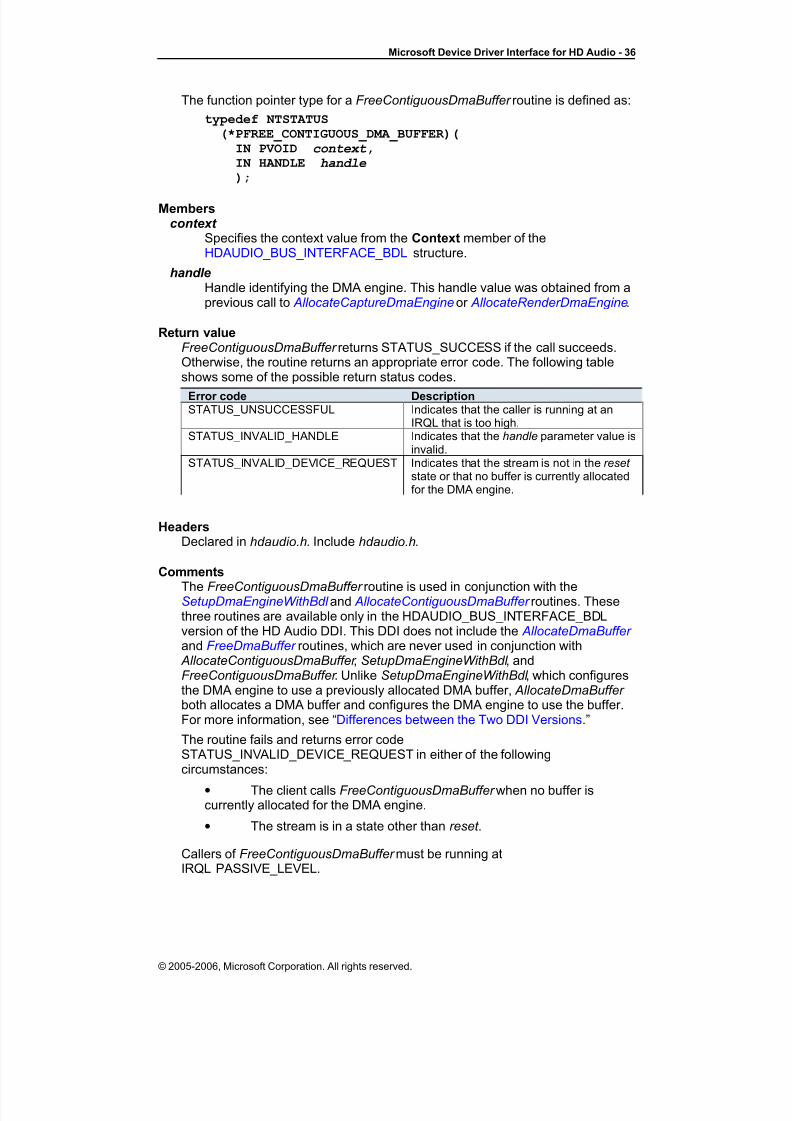
8/8/2019 HDAudioDdi11
http://slidepdf.com/reader/full/hdaudioddi11 36/69
Microsoft Device Driver Interface for HD Audio - 36
The function pointer type for a FreeContiguousDmaBuffer routine is defined as:
typedef NTSTATUS(*PFREE_CONTIGUOUS_DMA_BUFFER)(
IN PVOID context,IN HANDLE handle
);
Memberscontext
Specifies the context value from the Context member of theHDAUDIO_BUS_INTERFACE_BDL structure.
handleHandle identifying the DMA engine. This handle value was obtained from aprevious call to AllocateCaptureDmaEngine or AllocateRenderDmaEngine.
Return valueFreeContiguousDmaBuffer returns STATUS_SUCCESS if the call succeeds.Otherwise, the routine returns an appropriate error code. The following tableshows some of the possible return status codes.
Error code DescriptionSTATUS_UNSUCCESSFUL Indicates that the caller is running at an
IRQL that is too high.STATUS_INVALID_HANDLE Indicates that the handle parameter value is
invalid.STATUS_INVALID_DEVICE_REQUEST Indicates that the stream is not in the reset
state or that no buffer is currently allocatedfor the DMA engine.
HeadersDeclared in hdaudio.h. Include hdaudio.h.
Comments
The FreeContiguousDmaBuffer routine is used in conjunction with theSetupDmaEngineWithBdl and AllocateContiguousDmaBuffer routines. Thesethree routines are available only in the HDAUDIO_BUS_INTERFACE_BDLversion of the HD Audio DDI. This DDI does not include the AllocateDmaBuffer and FreeDmaBuffer routines, which are never used in conjunction with
AllocateContiguousDmaBuffer , SetupDmaEngineWithBdl , andFreeContiguousDmaBuffer . Unlike SetupDmaEngineWithBdl , which configuresthe DMA engine to use a previously allocated DMA buffer, AllocateDmaBuffer both allocates a DMA buffer and configures the DMA engine to use the buffer.For more information, see “Differences between the Two DDI Versions.”
The routine fails and returns error codeSTATUS_INVALID_DEVICE_REQUEST in either of the followingcircumstances:
• The client calls FreeContiguousDmaBuffer when no buffer iscurrently allocated for the DMA engine.
• The stream is in a state other than reset .
Callers of FreeContiguousDmaBuffer must be running atIRQL PASSIVE_LEVEL.
© 2005-2006, Microsoft Corporation. All rights reserved.

8/8/2019 HDAudioDdi11
http://slidepdf.com/reader/full/hdaudioddi11 37/69
Microsoft Device Driver Interface for HD Audio - 37
See AlsoHDAUDIO_BUS_INTERFACE_BDL, AllocateCaptureDmaEngine,
AllocateRenderDmaEngine, AllocateContiguousDmaBuffer , SetupDmaEngineWithBdl , AllocateDmaBuffer , FreeDmaBuffer
FreeDmaBuffer
The FreeDmaBuffer routine frees a DMA buffer that was previously allocated bya call to AllocateDmaBuffer .
The function pointer type for a FreeDmaBuffer routine is defined as:
typedef NTSTATUS(*PFREE_DMA_BUFFER)(
IN PVOID context,IN HANDLE handle
);
Parameterscontext
Specifies the context value from the Context member of the
HDAUDIO_BUS_INTERFACE structure.
handleHandle identifying the DMA engine. This handle value was obtained from aprevious call to AllocateCaptureDmaEngine or AllocateRenderDmaEngine.
Return ValueFreeDmaBuffer returns STATUS_SUCCESS if the call succeeds. Otherwise,the routine returns an appropriate error code. The following table shows someof the possible return status codes.
Error code DescriptionSTATUS_UNSUCCESSFUL Indicates that the caller is running at an
IRQL that is too high.STATUS_INVALID_HANDLE Indicates that the handle parameter value is
invalid.STATUS_INVALID_DEVICE_REQUEST Indicates that the stream is not in the reset
state or that no buffer is currently allocatedfor the DMA engine.
HeadersDeclared in hdaudio.h. Include hdaudio.h.
CommentsThe FreeDmaBuffer routine is used in conjunction with the AllocateDmaBuffer routine. These two routines are available only in theHDAUDIO_BUS_INTERFACE version of the HD Audio DDI. This DDI does notinclude the AllocateContiguousDmaBuffer , SetupDmaEngineWithBdl , and
FreeContiguousDmaBuffer routines, which are never used in conjunction with AllocateDmaBuffer and FreeDmaBuffer . Unlike SetupDmaEngineWithBdl ,which configures the DMA engine to use a previously allocated DMA buffer,
AllocateDmaBuffer both allocates a DMA buffer and configures the DMA engineto use the buffer.
© 2005-2006, Microsoft Corporation. All rights reserved.

8/8/2019 HDAudioDdi11
http://slidepdf.com/reader/full/hdaudioddi11 38/69
Microsoft Device Driver Interface for HD Audio - 38
The routine fails and returns error codeSTATUS_INVALID_DEVICE_REQUEST in either of the followingcircumstances:
• The client calls FreeDmaBuffer when no buffer is currentlyallocated for the DMA engine.
• The stream is in a state other than reset .
Callers of FreeDmaBuffer must be running at IRQL PASSIVE_LEVEL.
See Also AllocateDmaBuffer , HDAUDIO_BUS_INTERFACE, SetupDmaEngineWithBdl
FreeDmaBufferWithNotification
The FreeDmaBufferWithNotification routine frees a DMA buffer that waspreviously allocated by a call to AllocateDmaBufferWithNotification.
The function pointer type for a FreeDmaBufferWithNotification routine is definedas:
typedef NTSTATUS(*PFREE_DMA_BUFFER_WITH_NOTIFICATION)(
IN PVOID context,IN HANDLE handle,
IN PMDL bufferMdl,
IN SIZE_T bufferSize
);
Parameterscontext
Specifies the context value from the Context member of theHDAUDIO_BUS_INTERFACE_V2 structure.
handle
Handle identifying the DMA engine. This handle value was obtained from aprevious call to AllocateCaptureDmaEngine or AllocateRenderDmaEngine.
bufferMdl A pointer to the buffer MDL. This value was obtained from a previous call to
AllocateDmaBufferWithNotification.
bufferSizeThe size of the buffer to be free. This value was obtained from a previouscall to AllocateDmaBufferWithNotification.
Return ValueFreeDmaBufferWithNotification returns STATUS_SUCCESS if the callsucceeds. Otherwise, the routine returns an appropriate error code. Thefollowing table shows some of the possible return status codes.
Error code DescriptionSTATUS_UNSUCCESSFUL Indicates that the caller is running at an
IRQL that is too high.STATUS_INVALID_HANDLE Indicates that the handle parameter value is
invalid.STATUS_INVALID_DEVICE_REQUEST Indicates that the stream is not in the reset
state or that no buffer is currently allocatedfor the DMA engine.
© 2005-2006, Microsoft Corporation. All rights reserved.
8/8/2019 HDAudioDdi11
http://slidepdf.com/reader/full/hdaudioddi11 39/69
Microsoft Device Driver Interface for HD Audio - 39
HeadersDeclared in hdaudio.h. Include hdaudio.h.
CommentsThe FreeDmaBufferWithNotification routine is used in conjunction with the
AllocateDmaBufferWithNotification routine. These two routines are available
only in the HDAUDIO_BUS_INTERFACE_V2 version of the HD Audio DDI.The routine fails and returns error codeSTATUS_INVALID_DEVICE_REQUEST in either of the followingcircumstances:
• The client calls FreeDmaBufferWithNotificationwhen no buffer iscurrently allocated for the DMA engine.
• The stream is in a state other than reset .
Callers of FreeDmaBufferWithNotificationmust be running atIRQL PASSIVE_LEVEL.
See Also AllocateDmaBuffer WithNotification, HDAUDIO_BUS_INTERFACE_V2,SetupDmaEngineWithBdl
FreeDmaEngine
The FreeDmaEngine routine frees a DMA engine that was previously allocatedby a call to AllocateCaptureDmaEngine or AllocateRenderDmaEngine.
The function pointer type for a FreeDmaEngine routine is defined as:
typedef NTSTATUS(*PFREE_DMA_ENGINE)(
IN PVOID context,IN HANDLE handle
);
Parameterscontext
Specifies the context value from the Context member of theHDAUDIO_BUS_INTERFACE, HDAUDIO_BUS_INTERFACE_V2 or HDAUDIO_BUS_INTERFACE_BDL structure.
handleHandle identifying the DMA engine. This handle value was obtained from aprevious call to AllocateCaptureDmaEngine or AllocateRenderDmaEngine.
Return ValueFreeDmaEngine returns STATUS_SUCCESS if the call succeeds in freeing theDMA engine. Otherwise, the routine returns an appropriate error code. Thefollowing table shows some of the possible return status codes.
Error code DescriptionSTATUS_INVALID_HANDLE Indicates that the handle parameter value is
invalid.STATUS_INVALID_DEVICE_REQUEST Indicates that the stream is not in the reset
state or that a buffer is still allocated for theDMA engine.
HeadersDeclared in hdaudio.h. Include hdaudio.h.
© 2005-2006, Microsoft Corporation. All rights reserved.

8/8/2019 HDAudioDdi11
http://slidepdf.com/reader/full/hdaudioddi11 40/69
Microsoft Device Driver Interface for HD Audio - 40
CommentsThis routine frees a DMA engine that was previously reserved by a call to the
AllocateCaptureDmaEngine or AllocateRenderDmaEngine routine.
This routine fails and returns error codeSTATUS_INVALID_DEVICE_REQUEST in either of the followingcircumstances:
• Any previously allocated DMA buffer has not been freed (by callingFreeDmaBuffer or FreeContiguousDmaBuffer ).
• The stream is in a state other than reset .
An audio driver calls this routine to close the pin (and destroy the stream).
Callers of FreeDmaEngine must be running at IRQL <= DISPATCH_LEVEL.
See AlsoHDAUDIO_BUS_INTERFACE, HDAUDIO_BUS_INTERFACE_BDL,
AllocateCaptureDmaEngine, AllocateRenderDmaEngine, FreeDmaBuffer ,FreeContiguousDmaBuffer
GetDeviceInformation
The GetDeviceInformation routine retrieves information about the HD Audiocontroller device.
The function pointer type for a GetDeviceInformation routine is defined as:
typedef NTSTATUS
(*PGET_DEVICE_INFORMATION)(IN PVOID context,
IN OUT PHDAUDIO_DEVICE_INFORMATIONdeviceInformation
);
Parameters
context Specifies the context value from the Context member of theHDAUDIO_BUS_INTERFACE structure.
deviceInformationRetrieves information about the HD Audio controller device. This parameter points to a caller-allocated HDAUDIO_DEVICE_INFORMATION structureinto which the routine writes the device information.
Return ValueGetDeviceInformation returns STATUS_SUCCESS if the call succeeds.Otherwise, the routine returns an appropriate error code. The following tableshows one possible return status code.
Error code DescriptionSTATUS_BUFFER_TOO_SMALL Indicates that the size specified at the beginning of the deviceInformation buffer is too small.
HeadersDeclared in hdaudio.h. Include hdaudio.h.
© 2005-2006, Microsoft Corporation. All rights reserved.

8/8/2019 HDAudioDdi11
http://slidepdf.com/reader/full/hdaudioddi11 41/69
Microsoft Device Driver Interface for HD Audio - 41
CommentsThis routine retrieves device-dependent information that is static—that is, theinformation does not change dynamically over time.
The deviceInformation parameter is a pointer to a buffer that contains anHDAUDIO_DEVICE_INFORMATION structure into which the routine writesinformation about the HD Audio controller. Before calling GetDeviceInformation,
the caller allocates the buffer and writes the buffer’s size in bytes into the Sizemember at the beginning of the buffer.
Callers of GetDeviceInformation must be running at IRQL PASSIVE_LEVEL.
See AlsoHDAUDIO_BUS_INTERFACE, HDAUDIO_DEVICE_INFORMATION
GetLinkPositionRegister
The GetLinkPositionRegister routine retrieves a pointer to a DMA engine's linkposition register.
The function pointer type for a GetLinkPositionRegister routine is defined as:
typedef NTSTATUS(*PGET_LINK_POSITION_REGISTER)(
IN PVOID context,IN HANDLE handle,OUT PULONG * position );
Parameterscontext
Specifies the context value from the Context member of theHDAUDIO_BUS_INTERFACE, HDAUDIO_BUS_INTERFACE_V2 or HDAUDIO_BUS_INTERFACE_BDL structure.
handle
Handle that identifies the DMA engine. This handle value was obtainedfrom a previous call to AllocateCaptureDmaEngine or
AllocateRenderDmaEngine.
positionRetrieves a pointer to the link position register. This parameter points to acaller-allocated PULONG variable into which the routine writes a pointer tothe register. The HD Audio bus driver maps the register to a system virtualaddress that is accessible to the function driver.
Return ValueGetLinkPositionRegister returns STATUS_SUCCESS if the call succeeds.Otherwise, the routine returns an appropriate error code. The following tableshows one possible return status code.
Error code DescriptionSTATUS_INVALID_HANDLE Indicates that the handle parameter value is invalid.
HeadersDeclared in hdaudio.h. Include hdaudio.h.
CommentsFor more information, see “Wall Clock and Link Position Registers.”
© 2005-2006, Microsoft Corporation. All rights reserved.

8/8/2019 HDAudioDdi11
http://slidepdf.com/reader/full/hdaudioddi11 42/69
Microsoft Device Driver Interface for HD Audio - 42
Callers of GetLinkPositionRegister must be running atIRQL <= DISPATCH_LEVEL.
See AlsoHDAUDIO_BUS_INTERFACE, HDAUDIO_BUS_INTERFACE_BDL,
AllocateCaptureDmaEngine, AllocateRenderDmaEngine
GetResourceInformation
The GetResourceInformation routine retrieves information about hardwareresources.
The function pointer type for a GetResourceInformation routine is defined as:
void (*PGET_RESOURCE_INFORMATION)(
IN PVOID context,OUT UCHAR *codecAddress,OUT UCHAR *functionGroupStartNode);
Parameterscontext
Specifies the context value from the Context member of theHDAUDIO_BUS_INTERFACE, HDAUDIO_BUS_INTERFACE_V2 or HDAUDIO_BUS_INTERFACE_BDL structure.
codecAddressRetrieves a codec address. This parameter points to a caller-allocatedUCHAR variable into which the routine writes a codec address. The codecaddress identifies the SDI line on which the codec supplies response datato the HD Audio bus controller. A bus controller with n SDI pins can supportup to n codecs with addresses that range from 0 to n-1.
functionGroupStartNodeRetrieves the function group’s starting node ID. This parameter points to a
caller-allocated UCHAR variable into which the routine writes the node ID.For more information, see the following Comments section.
Return ValueNone
HeadersDeclared in hdaudio.h. Include hdaudio.h.
CommentsA codec contains one or more function groups. Each function group containssome number of nodes that are numbered sequentially beginning with thestarting node. For example, if a function group contains three nodes and the
starting node has a node ID of 9, the other two nodes in the function group havenode IDs 10 and 11. For more information, see the Intel High Definition AudioSpecification.
Callers of GetResourceInformation must be running at IRQL PASSIVE_LEVEL.
See AlsoHDAUDIO_BUS_INTERFACE, HDAUDIO_BUS_INTERFACE_BDL
© 2005-2006, Microsoft Corporation. All rights reserved.

8/8/2019 HDAudioDdi11
http://slidepdf.com/reader/full/hdaudioddi11 43/69
Microsoft Device Driver Interface for HD Audio - 43
GetWallClockRegister
The GetWallClockRegister routine retrieves a pointer to the wall clock register.
The function pointer type for a GetWallClockRegister routine is defined as:
typedef void (*PGET_WALL_CLOCK_REGISTER)(
IN PVOID context,OUT PULONG *wallclock );
Parameterscontext
Specifies the context value from the Context member of theHDAUDIO_BUS_INTERFACE, HDAUDIO_BUS_INTERFACE_V2 or HDAUDIO_BUS_INTERFACE_BDL structure.
wallclock Retrieves a pointer to the wall clock register. This parameter points to acaller-allocated PULONG variable into which the routine writes a pointer tothe register. The HD Audio bus driver maps the register to a system virtualaddress that is accessible to the function driver.
Return ValueNone
HeadersDeclared in hdaudio.h. Include hdaudio.h.
CommentsFor more information, see “Wall Clock and Link Position Registers.”
Callers of GetWallClockRegister must be running atIRQL <= DISPATCH_LEVEL.
See AlsoHDAUDIO_BUS_INTERFACE, HDAUDIO_BUS_INTERFACE_BDL
RegisterEventCallback
The RegisterEventCallback routine registers a callback routine for anunsolicited response from a codec or codecs.
The function pointer type for a RegisterEventCallback routine is defined as:
typedef NTSTATUS(*PREGISTER_EVENT_CALLBACK)(
IN PVOID context,IN PHDAUDIO_UNSOLICITED_RESPONSE_CALLBACK routine,IN PVOID callbackContext,
OUT UCHAR *tag );
Parameterscontext
Specifies the context value from the Context member of theHDAUDIO_BUS_INTERFACE, HDAUDIO_BUS_INTERFACE_V2 or HDAUDIO_BUS_INTERFACE_BDL structure.
© 2005-2006, Microsoft Corporation. All rights reserved.

8/8/2019 HDAudioDdi11
http://slidepdf.com/reader/full/hdaudioddi11 44/69
Microsoft Device Driver Interface for HD Audio - 44
routineFunction pointer to a callback routine. This parameter must be a valid, non-NULL function pointer of typePHDAUDIO_UNSOLICITED_RESPONSE_CALLBACK. For moreinformation, see the following Comments section.
callbackContext
Specifies a context value for the callback routine. The caller casts thecontext value to type PVOID. When a codec generates an unsolicitedresponse that contains the specified tag, the HD Audio bus driver passesthe context value to the callback routine as a call parameter.
tag Retrieves a tag value that identifies the unsolicited response. Thisparameter points to a caller-allocated UCHAR variable into which theroutine writes the tag value. The caller should specify this tag value whenprogramming the codec or codecs to generate the unsolicited response.For more information, see the following Comments section.
Return ValueRegisterEventCallback returns STATUS_SUCCESS if the call succeeds in
registering the event. Otherwise, the routine returns an appropriate error code.The following table shows one possible return status code.
Error code DescriptionSTATUS_INSUFFICIENT_RESOURCES Indicates that not enough resources are
available to complete the operation.
HeadersDeclared in hdaudio.h. Include hdaudio.h.
CommentsThis routine registers a callback routine for an unsolicited response from acodec. The routine outputs a tag to identify the unsolicited response. When theHD Audio bus driver encounters an unsolicited response from any codec with a
matching tag value, the routine calls the specified callback routine atIRQL DISPATCH_LEVEL and passes the specified context value to the routineas a call parameter.
Following the call to RegisterEventCallback , the function driver is responsiblefor programming the codec or codecs to generate unsolicited responses withthe specified tag.
The routine assigns a unique tag to each registered callback routine. Theunique association between tag and callback routine persists as long as thecallback routine remains registered. The function driver can delete theregistration of a callback routine by calling UnregisterEventCallback .
Currently, the bus driver can supply up to 64 unique tags per codec.
The callback parameter is a function pointer to a callback routine in the function
driver. The function pointer type for the callback routine is defined as:typedef VOID
(*PHDAUDIO_UNSOLICITED_RESPONSE_CALLBACK)
(HDAUDIO_CODEC_RESPONSE, PVOID);
The first call parameter is a structure of type HDAUDIO_CODEC_RESPONSE that specifies the codec’s response to the command. This structure is passedby value. The second call parameter is the callbackContext value that was
© 2005-2006, Microsoft Corporation. All rights reserved.

8/8/2019 HDAudioDdi11
http://slidepdf.com/reader/full/hdaudioddi11 45/69
Microsoft Device Driver Interface for HD Audio - 45
passed previously to RegisterEventCallback . The HD Audio bus driver calls thecallback routine at IRQL DISPATCH_LEVEL.
Callers of RegisterEventCallback must be running at IRQL PASSIVE_LEVEL.
See AlsoHDAUDIO_BUS_INTERFACE, HDAUDIO_BUS_INTERFACE_BDL,
UnregisterEventCallback , HDAUDIO_CODEC_RESPONSE
RegisterNotificationEvent
The RegisterNotificationEvent routine registers a kernel event so that it canreceive DMA progress notifications.
The function pointer type for a RegisterNotificationEvent routine is defined as:
typedef NTSTATUS(*PREGISTER_NOTIFICATION_EVENT)(
IN PVOID context,IN HANDLE handle,IN PKEVENT notificationEvent );
Parameterscontext
Specifies the context value from the Context member of theHDAUDIO_BUS_INTERFACE_V2 structure.
handleHandle that identifies the DMA engine. This handle value was obtainedfrom a previous call to AllocateCaptureDmaEngine or
AllocateRenderDmaEngine.
notificationEvent A pointer to a kernel event to be notified as DMA progresses. Dependingon the notification count parameter used with
AllocateDmaBufferWithNotification, the registered event will be signaledonce or twice per DMA pass through the audio buffer.
Return ValueRegisterNotificationEvent returns STATUS_SUCCESS if the call succeeds inregistering the event. Otherwise, the routine returns an appropriate error code.The following table shows one possible return status code.
Error code DescriptionSTATUS_INSUFFICIENT_RESOURCES Indicates that not enough resources are
available to complete the operation.
HeadersDeclared in hdaudio.h. Include hdaudio.h.
CommentsThis routine registers a kernel event with the HD Audio bus driver. TheHD Audio bus driver maintains a list of registered notification events for eachDMA engine and signals them each time the engine receives an IOC interrupt.Events are unregistered using UnregisterNotificationEvent .
Callers of RegisterNotificationEvent must be running atIRQL PASSIVE_LEVEL.
© 2005-2006, Microsoft Corporation. All rights reserved.

8/8/2019 HDAudioDdi11
http://slidepdf.com/reader/full/hdaudioddi11 46/69
Microsoft Device Driver Interface for HD Audio - 46
See AlsoHDAUDIO_BUS_INTERFACE_V2, UnregisterEventCallback
SetDmaEngineState
The SetDmaEngineState routine sets the state of one or more DMA engines tothe running , stopped , paused , or reset state.
The function pointer type for a SetDmaEngineState routine is defined as:
typedef NTSTATUS(*PSET_DMA_ENGINE_STATE)(
IN PVOID context,IN HDAUDIO_STREAM_STATE streamState,IN ULONG numberOfHandles,IN HANDLE *handles);
Parameterscontext
Specifies the context value from the Context member of theHDAUDIO_BUS_INTERFACE or HDAUDIO_BUS_INTERFACE_BDL
structure.
streamStateSpecifies the new stream state. Set this parameter to one of the followingHDAUDIO_STREAM_STATE enumeration values:
• PauseState (paused)
• ResetState (reset)
• RunState (running)
• StopState (stopped)
In the current implementation, PauseState and StopState represent thesame hardware state.
numberOfHandlesSpecifies the number of handles in the handles array. Set this parameter toa nonzero value.
handlesPointer to an array of handles to DMA engines. Specify a non-NULL valuefor this parameter.
Return ValueSetDmaEngineState returns STATUS_SUCCESS if the call succeeds inchanging the DMA engines' states. Otherwise, the routine returns anappropriate error code. The following table shows some of the possible returnstatus codes.
Error code DescriptionSTATUS_INVALID_HANDLE Indicates that one of the handles is invalid.STATUS_INVALID_PARAMETER Indicates that one of the parameter values
is incorrect (invalid parameter value or badpointer).
STATUS_INVALID_DEVICE_REQUEST Indicates that no buffer is currentlyallocated for one of the DMA engines.
HeadersDeclared in hdaudio.h. Include hdaudio.h.
© 2005-2006, Microsoft Corporation. All rights reserved.

8/8/2019 HDAudioDdi11
http://slidepdf.com/reader/full/hdaudioddi11 47/69
Microsoft Device Driver Interface for HD Audio - 47
CommentsThis routine changes the state of one or more DMA engines to the state that thestreamState parameter specifies. The routine synchronizes the state transitionsof all the DMA engines that the handles in the handles array identify. For moreinformation, see “Synchronizing Two or More Streams.”
Before calling this routine, set up each DMA engine in the handles array:
• If using the HDAUDIO_BUS_INTERFACE version of the HD AudioDDI, call AllocateDmaBuffer to set up the DMA engine.
• If using the HDAUDIO_BUS_INTERFACE_BDL version of the DDI,call SetupDmaEngineWithBdl to set up the DMA engine.
If no DMA buffer is currently allocated for any DMA engine in the handles array,an attempt to change the stream to any state other than reset causes theSetDmaEngineState call to fail and return error codeSTATUS_INVALID_DEVICE_REQUEST.
The stream state cannot transition directly between running and reset . Instead,the stream must first pass through an intermediate state of paused or stopped :
• From a running or reset state, the stream state can change directly
to either paused or stopped .
• From a paused or stopped state, the stream state can changedirectly to either running or reset .
A WDM audio driver calls this routine during a call to its SetState method (for example, see the description of the IMiniportWaveRTStream::SetStatemethod in the Windows DDK documentation).
Callers of SetDmaEngineState must be running atIRQL <= DISPATCH_LEVEL.
See AlsoHDAUDIO_BUS_INTERFACE, HDAUDIO_BUS_INTERFACE_BDL,
AllocateDmaBuffer , SetupDmaEngineWithBdl
SetupDmaEngineWithBdl
The SetupDmaEngineWithBdl routine sets up a DMA engine to use a caller-allocated DMA buffer.
The function pointer type for a SetupDmaEngineWithBdl routine is defined as:
typedef NTSTATUS(*PSETUP_DMA_ENGINE_WITH_BDL)(
IN PVOID context,IN HANDLE handle,IN ULONG bufferSize,IN ULONG lvi,
IN PHDAUDIO_BDL_ISR isr ,IN VOID *callbackContext,OUT UCHAR *streamID ,OUT UINT *fifoSize);
Parameterscontext
Specifies the context value from the Context member of theHDAUDIO_BUS_INTERFACE_BDL structure.
© 2005-2006, Microsoft Corporation. All rights reserved.
8/8/2019 HDAudioDdi11
http://slidepdf.com/reader/full/hdaudioddi11 48/69
Microsoft Device Driver Interface for HD Audio - 48
handleHandle that identifies the DMA engine. This handle value was obtainedfrom a previous call to AllocateCaptureDmaEngine or
AllocateRenderDmaEngine.
bufferSizeSpecifies the size in bytes of the DMA buffer that the bdl array describes.
lvi Specifies the last valid index (LVI). This parameter contains the index for the last valid buffer descriptor in the BDL. After the DMA engine processesthis descriptor, it wraps back to the first descriptor in the list and continuesprocessing. If the BDL contains n descriptors, they are numbered 0 to n-1.The lvi value must be at least 1; in other words, the BDL must contain atleast two valid entries before the DMA engine can begin operation.
isr Function pointer to the caller’s ISR. If the caller sets the IOC bit in one or more of the buffer descriptors in the BDL, the HD Audio bus driver calls theISR each time an IOC interrupt occurs on the stream. This parameter is afunction pointer of type HDAUDIO_BDL_ISR, which is defined in thefollowing Comments section.
callbackContext Specifies a context value that the HD Audio bus driver passes to the ISR.
streamIDRetrieves the stream identifier. This parameter points to a caller-allocatedUCHAR variable into which the routine writes the stream identifier that itassigns to the stream.
fifoSizeRetrieves the DMA engine's FIFO size in bytes. This parameter points to acaller-allocated UINT variable into which the routine writes the FIFO size.
Return ValueSetupDmaEngineWithBdl returns STATUS_SUCCESS if the call succeeds.
Otherwise, the routine returns an appropriate error code. The following tableshows some of the possible return status codes.
Error code DescriptionSTATUS_UNSUCCESSFUL Indicates that the caller is running at an
IRQL that is too high.STATUS_INVALID_HANDLE Indicates that the handle parameter value is
invalid.STATUS_INVALID_PARAMETER Indicates that one of the parameter values
is incorrect (bad pointer or invalid streamformat).
STATUS_DEVICE_NOT_READY Indicates that the hardware programmingtimed out. If this occurs, the hardware mightbe in a compromised state.
STATUS_INVALID_DEVICE_REQUEST Indicates that the DMA device or DMA
buffer is not allocated or the stream is not inthe reset state.
HeadersDeclared in hdaudio.h. Include hdaudio.h.
CommentsThe SetupDmaEngineWithBdl routine is used in conjunction with the
AllocateContiguousDmaBuffer and FreeContiguousDmaBuffer routines. These
© 2005-2006, Microsoft Corporation. All rights reserved.

8/8/2019 HDAudioDdi11
http://slidepdf.com/reader/full/hdaudioddi11 49/69
Microsoft Device Driver Interface for HD Audio - 49
three routines are available only in the HDAUDIO_BUS_INTERFACE_BDLversion of the HD Audio DDI. This DDI does not include the AllocateDmaBuffer and FreeDmaBuffer routines, which are never used in conjunction with
AllocateContiguousDmaBuffer , SetupDmaEngineWithBdl , andFreeContiguousDmaBuffer . Unlike SetupDmaEngineWithBdl , which configuresthe DMA engine to use a previously allocated DMA buffer, AllocateDmaBuffer both allocates a DMA buffer and configures the DMA engine to use the buffer.
The caller must call AllocateContiguousDmaBuffer to allocate storage in thesystem memory for both the DMA buffer and the BDL that describes thephysical memory pages in the buffer. The BDL entries must reside in memorythat is physically contiguous. The BDL and buffer memory must meet thealignment requirements that are described in the Intel High Definition AudioSpecification.
Both the BDL and the buffer memory that it describes must remain valid duringDMA operations. Following the call to SetupDmaEngineWithBdl , the BDL andbuffer memory must remain valid as long as the DMA engine continues to usethe buffer. The DMA engine uses the buffer until the function driver replaces thebuffer by calling SetupDmaEngineWithBdl again or frees the DMA engine bycalling FreeDmaEngine. The function driver is responsible for calling
FreeContigousDmaBuffer to free the buffer and BDL when they are no longer required.
When allocating memory for the buffer, the caller must satisfy all hardwareconstraints for the address, length, and alignment of the physically contiguousblocks of memory that the BDL specifies. Thus, only clients with significantknowledge of the bus controller and system hardware should use theSetupDmaEngineWithBdl routine.
Before calling SetupDmaEngineWithBdl to configure a DMA engine, the clientmust call AllocateCaptureDmaEngine or AllocateRenderDmaEngine to allocatethe DMA engine. The handle parameter is the value obtained from thepreceding call to AllocateXxxDmaEngine.
The caller is responsible for programming the codec to manage the data
transfers and to recognize the stream identifier.A WDM audio driver calls this routine at pin-creation time during execution of itsNewStream method (for example, see the description of theIMiniportWavePci::NewStreammethod in the Windows DDK documentation).
Following the call to SetupDmaEngineWithBdl , the DMA engine is in the reset state. To start the DMA engine, call SetDmaEngineState.
Parameter isr specifies the ISR that the HD Audio bus driver is to call each timean IOC interrupt occurs on the stream. This parameter is a function pointer of type HDAUDIO_BDL_ISR, which is defined as:
VOID (*PHDAUDIO_BDL_ISR)(IN VOID *context,IN ULONG interruptBitMask);
© 2005-2006, Microsoft Corporation. All rights reserved.

8/8/2019 HDAudioDdi11
http://slidepdf.com/reader/full/hdaudioddi11 50/69
Microsoft Device Driver Interface for HD Audio - 50
The HD Audio bus driver calls the ISR with the same context value that theclient specified in the context parameter of the precedingSetupDmaEngineWithBdl call. The interruptBitMask parameter contains the bitsfrom the HD Audio controller device’s stream status register that indicate thereason for the interrupt. The following table shows the meaning of the individualbits in interruptBitMask .
Bitnumbers
Meaning
31:5 Unused.4 Descriptor Error (DESE). If an error occurs during the fetch of a buffer
descriptor, then the HD Audio controller sets the DESE bit to 1.3 FIFO Error (FIFOE). If a FIFO error occurs (an overrun on an output
stream or an underrun on an input stream), then the HD Audiocontroller sets the FIFOE bit to 1.
2 Buffer Completion Interrupt Status (BCIS). If the IOC bit is set to 1 inthe command byte of the buffer descriptor, then the HD Audiocontroller sets the BCIS bit to 1 after the last sample of a buffer isprocessed.
1:0 Unused.
The HD Audio bus driver sets the unused bits to zero. Instead of assuming that
an IOC interrupt has occurred, the ISR must always check the interruptBitMask parameter to determine whether a stream error has occurred. For moreinformation about the interrupt status bits shown in the preceding table, see thedescription of the stream status registers in the Intel High Definition AudioSpecification.
The FIFO size is the maximum number of bytes that the DMA engine can holdin its internal buffer at any one time. Depending on the hardwareimplementation, a DMA engine’s FIFO size can either be static or varydynamically with changes in the stream format. For more information about theFIFO size, see the Intel High Definition Audio Specification.
Callers of SetupDmaEngineWithBdl must be running atIRQL PASSIVE_LEVEL.
The caller must allocate the buffer memory and BDL from the nonpaged pool.
See AlsoHDAUDIO_BUS_INTERFACE_BDL, HDAUDIO_BUFFER_DESCRIPTOR,
AllocateDmaBuffer , FreeDmaBuffer , AllocateCaptureDmaEngine, AllocateRenderDmaEngine, SetDmaEngineState
TransferCodecVerbs
The TransferCodecVerbs routine transfers one or more commands to a codecor codecs and retrieves the responses to those commands.
The function pointer type for a TransferCodecVerbs routine is defined as:
typedef NTSTATUS
(*PTRANSFER_CODEC_VERBS)(IN PVOID context,IN ULONG count,IN OUT PHDAUDIO_CODEC_TRANSFER codecTransfer ,IN PHDAUDIO_TRANSFER_COMPLETE_CALLBACK callback ,IN PVOID callbackContext
);
© 2005-2006, Microsoft Corporation. All rights reserved.

8/8/2019 HDAudioDdi11
http://slidepdf.com/reader/full/hdaudioddi11 51/69

8/8/2019 HDAudioDdi11
http://slidepdf.com/reader/full/hdaudioddi11 52/69
Microsoft Device Driver Interface for HD Audio - 52
• If the caller specifies a non-NULL value for the callback parameter,the routine operates asynchronously. (In other words, the routine returnsimmediately after adding the commands to its internal queue withoutwaiting for the codecs to process all the commands.) After the codecsprocess the commands, the HD Audio bus driver calls the callback routine.In the asynchronous case, the caller should not attempt to read the
responses to the commands before the bus driver calls the callback routine.
The function pointer type for the callback parameter is defined as:
typedef void (*PHDAUDIO_TRANSFER_COMPLETE_CALLBACK)
(HDAUDIO_CODEC_TRANSFER *, PVOID);
The first call parameter is a pointer to the codecTransfer array element thatcontains the codec command and the response that triggered the callback. Thesecond call parameter is the same context value that was specified previouslyin the TransferCodecVerbs routine’s callbackContext parameter.
If successful, TransferCodecVerbs returns STATUS_SUCCESS. The meaningof this status code depends on whether the routine operates synchronously or
asynchronously:• In the synchronous case (callback is NULL), STATUS_SUCCESSmeans that the bus driver has all the commands in the codecTransfer arrayto the codecs and that the routine has written all the responses to thosecommands into the array. However, the caller must check the individualresponses to determine whether they are valid. Individual responses mightbe invalid due to codec timeouts or FIFO overrun.
• In the asynchronous case (callback is non-NULL),STATUS_SUCCESS means only that the routine has successfully addedthe commands to the HD Audio bus driver's internal queue. The caller mustnot attempt to read the responses to those commands until the bus driver calls the callback routine.
If a response is invalid due to a FIFO overrun, the likely cause is that the codecresponded to the command but the response was lost due to an insufficientlysized RIRB. If a FIFO overrun is not the cause of the invalid response, thefailure probably occurred because the codec did not respond in time (timedout). In this case, the caller can assume that the command did not reach thecodec.
If the callback parameter is NULL, the caller must be running atIRQL PASSIVE_LEVEL. If callback is non-NULL, the caller can callTransferCodecVerbs at IRQL <= DISPATCH_LEVEL, in which case the callreturns immediately without waiting for the codecs to process all thecommands; after the commands complete, the HD Audio bus driver calls thecallback routine at IRQL DISPATCH_LEVEL.
The caller must allocate the codecTransfer array from the nonpaged pool.
See AlsoHDAUDIO_BUS_INTERFACE, HDAUDIO_BUS_INTERFACE_V2, HDAUDIO_BUS_INTERFACE_BDL, HDAUDIO_CODEC_TRANSFER
UnregisterEventCallback
The UnregisterEventCallback routine deletes the registration of an eventcallback that was previously registered by a call to RegisterEventCallback .
© 2005-2006, Microsoft Corporation. All rights reserved.

8/8/2019 HDAudioDdi11
http://slidepdf.com/reader/full/hdaudioddi11 53/69
Microsoft Device Driver Interface for HD Audio - 53
The function pointer type for an UnregisterEventCallback routine is defined as:
typedef NTSTATUS(*PUNREGISTER_EVENT_CALLBACK)(
IN PVOID context,IN UCHAR tag
);
Parameterscontext
Specifies the context value from the Context member of theHDAUDIO_BUS_INTERFACE, HDAUDIO_BUS_INTERFACE_V2 or HDAUDIO_BUS_INTERFACE_BDL structure.
tag Specifies the tag value that was associated with the callback by thepreceding call to RegisterEventCallback .
Return ValueUnregisterEventCallback returns STATUS_SUCCESS if the call succeeds inchanging the DMA engines' states. Otherwise, the routine returns an
appropriate error code. The following table shows one possible return statuscode.
Error code DescriptionSTATUS_INVALID_PARAMETER Indicates that the specified tag is not valid.
HeadersDeclared in hdaudio.h. Include hdaudio.h.
CommentsBefore calling this routine, the function driver is responsible for programmingthe codec or codecs to remove the association of the callback with the specifiedtag.
Callers of UnregisterEventCallback must be running at IRQL PASSIVE_LEVEL.
See AlsoRegisterEventCallback , HDAUDIO_ BUS_INTERFACE, HDAUDIO_BUS_INTERFACE_BDL
UnregisterNotificationEvent
The UnregisterNotificationEvent routine deletes the registration of an event thatwas previously registered by a call to RegisterNotificationEvent .
The function pointer type for an UnregisterNotificationEvent routine is definedas:
typedef NTSTATUS(*PUNREGISTER_NOTIFICATION_EVENT)(
IN PVOID context,IN HANDLE handle,IN PKEVENT notificationEvent );
Parameterscontext
Specifies the context value from the Context member of theHDAUDIO_BUS_INTERFACE_V2 structure.
© 2005-2006, Microsoft Corporation. All rights reserved.

8/8/2019 HDAudioDdi11
http://slidepdf.com/reader/full/hdaudioddi11 54/69
Microsoft Device Driver Interface for HD Audio - 54
handleHandle that identifies the DMA engine. This handle value was obtainedfrom a previous call to AllocateCaptureDmaEngine or
AllocateRenderDmaEngine.
notificationEvent A pointer to a kernel event previously registered for DMA progress
notification with a call to RegisterNotificationEvent .
Return ValueUnregisterNotificationEvent returns STATUS_SUCCESS if the call succeeds inunregistering the notification event. Otherwise, the routine returns anappropriate error code. The following table shows one possible return statuscode.
Error code DescriptionSTATUS_INVALID_PARAMETER Indicates that the specified tag is not valid.
HeadersDeclared in hdaudio.h. Include hdaudio.h.
CommentsCallers of UnregisterNotificationEvent must be running atIRQL PASSIVE_LEVEL.
See AlsoRegisterNotificationEvent , HDAUDIO_ BUS_INTERFACE_V2
Structure Types
The routines in both versions of the HD Audio DDI use the following structuretypes:
HDAUDIO_BUFFER_DESCRIPTORHDAUDIO_BUS_INTERFACE
HDAUDIO_BUS_INTERFACE_V2HDAUDIO_BUS_INTERFACE_BDLHDAUDIO_CODEC_COMMANDHDAUDIO_CODEC_RESPONSEHDAUDIO_CODEC_TRANSFERHDAUDIO_CONVERTER_FORMATHDAUDIO_DEVICE_INFORMATIONHDAUDIO_STREAM_FORMAT
HDAUDIO_BUFFER_DESCRIPTOR
The HDAUDIO_BUFFER_DESCRIPTOR structure specifies a buffer descriptor,which is an entry in a BDL.
typedef struct _HDAUDIO_BUFFER_DESCRIPTOR {PHYSICAL_ADDRESS Address;ULONG Length;ULONG InterruptOnCompletion;
} HDAUDIO_BUFFER_DESCRIPTOR,*PHDAUDIO_BUFFER_DESCRIPTOR;
© 2005-2006, Microsoft Corporation. All rights reserved.

8/8/2019 HDAudioDdi11
http://slidepdf.com/reader/full/hdaudioddi11 55/69
Microsoft Device Driver Interface for HD Audio - 55
MembersAddress
Specifies the start address of a physically contiguous fragment of thebuffer. In the case of a 32-bit address, the address should be right-justifiedand the 32 most significant bits (MSBs) of the member should be zero.
Length
Specifies the size in bytes of the buffer fragment.InterruptOnCompletion
Specifies whether the DMA engine should generate an interrupt oncompleting the transfer of the buffer fragment. A value of 1 enables theinterrupt. A value of 0 disables it.
HeadersDeclared in hdaudio.h. Include hdaudio.h.
CommentsA BDL is an array of HDAUDIO_BUFFER_DESCRIPTOR structures. Eachstructure specifies a physically contiguous fragment of the buffer. A BDLspecifies all the fragments that make up the buffer.
The Address member contains the physical memory address of the start of thebuffer fragment. The Length member specifies the number of bytes of physically contiguous memory that the fragment contains.
If the InterruptOnCompletion bit is set during a DMA transfer to or from thebuffer fragment, the DMA engine generates an interrupt on completion of thetransfer.
This structure is used by the AllocateContiguousDmaBuffer andSetupDmaEngineWithBdl routines.
For more information about BDLs, see the Intel High Definition AudioSpecification.
See Also
SetupDmaEngineWithBdl
HDAUDIO_BUS_INTERFACE
The HDAUDIO_BUS_INTERFACE structure specifies the information that aclient requires to call the routines in the HDAUDIO_BUS_INTERFACE versionof the HD Audio DDI. Another variant of this DDI is specified by theHDAUDIO_BUS_INTERFACE_BDL structure.
typedef struct _ HDAUDIO_BUS_INTERFACE{USHORT Size;USHORT Version;PVOID Context;PINTERFACE_REFERENCE InterfaceReference;PINTERFACE_DEREFERENCE InterfaceDereference;
© 2005-2006, Microsoft Corporation. All rights reserved.

8/8/2019 HDAudioDdi11
http://slidepdf.com/reader/full/hdaudioddi11 56/69
Microsoft Device Driver Interface for HD Audio - 56
PTRANSFER_CODEC_VERBS TransferCodecVerbs;PALLOCATE_CAPTURE_DMA_ENGINE
AllocateCaptureDmaEngine;PALLOCATE_RENDER_DMA_ENGINE AllocateRenderDmaEngine;PCHANGE_BANDWIDTH_ALLOCATION
ChangeBandwidthAllocation;PALLOCATE_DMA_BUFFER AllocateDmaBuffer;PFREE_DMA_BUFFER FreeDmaBuffer;PFREE_DMA_ENGINE FreeDmaEngine;PSET_DMA_ENGINE_STATE SetDmaEngineState;PGET_WALL_CLOCK_REGISTER GetWallClockRegister;PGET_LINK_POSITION_REGISTER GetLinkPositionRegister;PREGISTER_EVENT_CALLBACK RegisterEventCallback;PUNREGISTER_EVENT_CALLBACK UnregisterEventCallback;PGET_DEVICE_INFORMATION GetDeviceInformation;PGET_RESOURCE_INFORMATION GetResourceInformation;
} HDAUDIO_BUS_INTERFACE, *PHDAUDIO_BUS_INTERFACE;
MembersSize
Specifies the size in bytes of the HDAUDIO_BUS_INTERFACE structure.
VersionSpecifies the version of the baseline HD Audio DDI.
ContextPointer to interface-specific context information.
InterfaceReferencePointer to a driver-supplied routine that increments the interface's referencecount.
InterfaceDereferencePointer to a driver-supplied routine that decrements the interface'sreference count.
TransferCodecVerbsFunction pointer to the TransferCodecVerbs routine.
AllocateCaptureDmaEngineFunction pointer to the AllocateCaptureDmaEngine routine.
AllocateRenderDmaEngineFunction pointer to the AllocateRenderDmaEngine routine.
ChangeBandwidthAllocationFunction pointer to the ChangeBandwidthAllocation routine.
AllocateDmaBuffer Function pointer to the AllocateDmaBuffer routine.
FreeDmaBuffer Function pointer to the FreeDmaBuffer routine.
FreeDmaEngineFunction pointer to the FreeDmaEngine routine.
SetDmaEngineStateFunction pointer to the SetDmaEngineState routine.
GetWallClockRegister Function pointer to the GetWallClockRegister routine.
GetLinkPositionRegister Function pointer to the GetLinkPositionRegister routine.
© 2005-2006, Microsoft Corporation. All rights reserved.

8/8/2019 HDAudioDdi11
http://slidepdf.com/reader/full/hdaudioddi11 57/69
Microsoft Device Driver Interface for HD Audio - 57
RegisterEventCallbackFunction pointer to the RegisterEventCallback routine.
UnregisterEventCallbackFunction pointer to the UnregisterEventCallback routine.
GetDeviceInformationFunction pointer to the GetDeviceInformation routine.
GetResourceInformationFunction pointer to the GetResourceInformation routine.
HeadersDeclared in hdaudio.h. Include hdaudio.h.
CommentsThe IRP_MN_QUERY_INTERFACE IOCTL uses this structure to provideinterface information to a client that is querying the HD Audio bus driver for theHD Audio DDI. Another variant of this DDI is specified by theHDAUDIO_BUS_INTERFACE_BDL structure.
The HDAUDIO_BUS_INTERFACE and HDAUDIO_BUS_INTERFACE_BDL
structures are similar but have the following differences:• HDAUDIO_BUS_INTERFACE has two members,AllocateDmaBuffer and FreeDmaBuffer , that are not present inHDAUDIO_BUS_INTERFACE_BDL.
• HDAUDIO_BUS_INTERFACE_BDL has three members,AllocateContiguousDmaBuffer , FreeContiguousDmaBuffer , andSetupDmaEngineWithBdl , that are not present inHDAUDIO_BUS_INTERFACE.
For more information, see “Differences between the Two DDI Versions.”
The names and definitions of the first five members (Size, Version, Context,InterfaceReference, and InterfaceDereference) are the same as in theINTERFACE structure. The remaining members are specific to the baselineHD Audio DDI and specify function pointers to the routines in the DDI. For moreinformation, see “Obtaining an HDAUDIO_BUS_INTERFACE DDI Object.”
See AlsoTransferCodecVerbs, AllocateCaptureDmaEngine, AllocateRenderDmaEngine,ChangeBandwidthAllocation, AllocateDmaBuffer , FreeDmaBuffer , FreeDmaEngine, SetDmaEngineState, GetWallClockRegister ,GetLinkPositionRegister , RegisterEventCallback , UnregisterEventCallback ,GetDeviceInformation, GetResourceInformation, HDAUDIO_BUS_INTERFACE_BDL
© 2005-2006, Microsoft Corporation. All rights reserved.

8/8/2019 HDAudioDdi11
http://slidepdf.com/reader/full/hdaudioddi11 58/69
Microsoft Device Driver Interface for HD Audio - 58
HDAUDIO_BUS_INTERFACE_V2
The HDAUDIO_BUS_INTERFACE_V2 structure specifies the information that aclient requires to call the routines in the HDAUDIO_BUS_INTERFACE_V2version of the HD Audio DDI. The interface represented by this structureprovides all the functionality of HDAUDIO_BUS_INTERFACE with the addedcapability of supporting flexible DMA driven event notification.
typedef struct _ HDAUDIO_BUS_INTERFACE_V2{USHORT Size;USHORT Version;PVOID Context;PINTERFACE_REFERENCE InterfaceReference;PINTERFACE_DEREFERENCE InterfaceDereference;
PTRANSFER_CODEC_VERBS TransferCodecVerbs;PALLOCATE_CAPTURE_DMA_ENGINE
AllocateCaptureDmaEngine;PALLOCATE_RENDER_DMA_ENGINE AllocateRenderDmaEngine;PCHANGE_BANDWIDTH_ALLOCATION
ChangeBandwidthAllocation;
PALLOCATE_DMA_BUFFER AllocateDmaBuffer;PFREE_DMA_BUFFER FreeDmaBuffer;PFREE_DMA_ENGINE FreeDmaEngine;PSET_DMA_ENGINE_STATE SetDmaEngineState;PGET_WALL_CLOCK_REGISTER GetWallClockRegister;PGET_LINK_POSITION_REGISTER GetLinkPositionRegister;PREGISTER_EVENT_CALLBACK RegisterEventCallback;PUNREGISTER_EVENT_CALLBACK UnregisterEventCallback;PGET_DEVICE_INFORMATION GetDeviceInformation;PGET_RESOURCE_INFORMATION GetResourceInformation;PALLOCATE_DMA_BUFFER_WITH_NOTIFICATION
AllocateDmaBufferWithNotification;PFREE_DMA_BUFFER_WITH_NOTIFICATION
FreeDmaBufferWithNotification;PREGISTER_NOTIFICATION_EVENTRegisterNotificationEvent;PUNREGISTER_NOTIFICATION_EVENT
UnregisterNotificationEvent;} HDAUDIO_BUS_INTERFACE, *PHDAUDIO_BUS_INTERFACE;
MembersSize
Specifies the size in bytes of the HDAUDIO_BUS_INTERFACE structure.
VersionSpecifies the version of the baseline HD Audio DDI.
Context
Pointer to interface-specific context information.InterfaceReference
Pointer to a driver-supplied routine that increments the interface's referencecount.
InterfaceDereferencePointer to a driver-supplied routine that decrements the interface'sreference count.
© 2005-2006, Microsoft Corporation. All rights reserved.

8/8/2019 HDAudioDdi11
http://slidepdf.com/reader/full/hdaudioddi11 59/69
Microsoft Device Driver Interface for HD Audio - 59
TransferCodecVerbsFunction pointer to the TransferCodecVerbs routine.
AllocateCaptureDmaEngineFunction pointer to the AllocateCaptureDmaEngine routine.
AllocateRenderDmaEngineFunction pointer to the AllocateRenderDmaEngine routine.
ChangeBandwidthAllocationFunction pointer to the ChangeBandwidthAllocation routine.
AllocateDmaBuffer Function pointer to the AllocateDmaBuffer routine.
FreeDmaBuffer Function pointer to the FreeDmaBuffer routine.
FreeDmaEngineFunction pointer to the FreeDmaEngine routine.
SetDmaEngineStateFunction pointer to the SetDmaEngineState routine.
GetWallClockRegister
Function pointer to the GetWallClockRegister routine.GetLinkPositionRegister
Function pointer to the GetLinkPositionRegister routine.
RegisterEventCallbackFunction pointer to the RegisterEventCallback routine.
UnregisterEventCallbackFunction pointer to the UnregisterEventCallback routine.
GetDeviceInformationFunction pointer to the GetDeviceInformation routine.
GetResourceInformationFunction pointer to the GetResourceInformation routine.
AllocateDmaBufferWithNotificationFunction pointer to the AllocateDmaBufferWithNotification routine.
FreeDmaBufferWithNotificationFunction pointer to the FreeDmaBufferWithNotification routine.
RegisterNotificationEventFunction pointer to the RegisterNotificationEvent routine.
UnregisterNotificationEventFunction pointer to the UnregisterNotificationEvent routine.
HeadersDeclared in hdaudio.h. Include hdaudio.h.
CommentsThe IRP_MN_QUERY_INTERFACE IOCTL uses this structure to provideinterface information to a client that is querying the HD Audio bus driver for theHD Audio DDI.
For more information, see “Differences between the DDI Versions.”
The names and definitions of the first five members (Size, Version, Context,InterfaceReference, and InterfaceDereference) are the same as in theINTERFACE structure. The remaining members are specific to the baseline
© 2005-2006, Microsoft Corporation. All rights reserved.

8/8/2019 HDAudioDdi11
http://slidepdf.com/reader/full/hdaudioddi11 60/69
Microsoft Device Driver Interface for HD Audio - 60
HD Audio DDI and specify function pointers to the routines in the DDI. For moreinformation, see “Obtaining an HDAUDIO_BUS_INTERFACE_V2 DDI Object.”
See AlsoTransferCodecVerbs, AllocateCaptureDmaEngine, AllocateRenderDmaEngine,ChangeBandwidthAllocation, AllocateDmaBuffer , FreeDmaBuffer ,
FreeDmaEngine, SetDmaEngineState, GetWallClockRegister ,GetLinkPositionRegister , RegisterEventCallback , UnregisterEventCallback ,GetDeviceInformation, GetResourceInformation,
AllocateDmaBufferWithNotification, FreeDmaBufferWithNotification, RegisterNotificationEvent , UnregisterNotificationEvent , HDAUDIO_BUS_INTERFACE, HDAUDIO_BUS_INTERFACE_BDL
HDAUDIO_BUS_INTERFACE_BDL
The HDAUDIO_BUS_INTERFACE_BDL structure specifies the information thata client requires to call the routines in the HDAUDIO_BUS_INTERFACE_BDLversion of the HD Audio DDI. Another variant of this DDI is specified by theHDAUDIO_BUS_INTERFACE structure.
typedef struct _HDAUDIO_BUS_INTERFACE_BDL
{USHORT Size;USHORT Version;PVOID Context;PINTERFACE_REFERENCE InterfaceReference;PINTERFACE_DEREFERENCE InterfaceDereference;
PTRANSFER_CODEC_VERBS TransferCodecVerbs;PALLOCATE_CAPTURE_DMA_ENGINE
AllocateCaptureDmaEngine;PALLOCATE_RENDER_DMA_ENGINE AllocateRenderDmaEngine;PCHANGE_BANDWIDTH_ALLOCATION
ChangeBandwidthAllocation;PALLOCATE_CONTIGUOUS_DMA_BUFFER
AllocateContiguousDmaBuffer;PSETUP_DMA_ENGINE_WITH_BDL SetupDmaEngineWithBdl;PFREE_CONTIGUOUS_DMA_BUFFER FreeContiguousDmaBuffer;PFREE_DMA_ENGINE FreeDmaEngine;PSET_DMA_ENGINE_STATE SetDmaEngineState;PGET_WALL_CLOCK_REGISTER GetWallClockRegister;PGET_LINK_POSITION_REGISTER GetLinkPositionRegister;PREGISTER_EVENT_CALLBACK RegisterEventCallback;PUNREGISTER_EVENT_CALLBACK UnregisterEventCallback;PGET_DEVICE_INFORMATION GetDeviceInformation;PGET_RESOURCE_INFORMATION GetResourceInformation;
} HDAUDIO_BUS_INTERFACE_BDL,*PHDAUDIO_BUS_INTERFACE_BDL;
MembersSize
Specifies the size in bytes of the HDAUDIO_BUS_INTERFACE_BDLstructure.
VersionSpecifies the version of the extended HD Audio DDI.
© 2005-2006, Microsoft Corporation. All rights reserved.

8/8/2019 HDAudioDdi11
http://slidepdf.com/reader/full/hdaudioddi11 61/69

8/8/2019 HDAudioDdi11
http://slidepdf.com/reader/full/hdaudioddi11 62/69
Microsoft Device Driver Interface for HD Audio - 62
The HDAUDIO_BUS_INTERFACE_BDL and HDAUDIO_BUS_INTERFACEstructures are similar but have the following differences:
• HDAUDIO_BUS_INTERFACE_BDL has three members,AllocateContiguousDmaBuffer , SetupDmaEngineWithBdl , andFreeContiguousDmaBuffer , that are not present inHDAUDIO_BUS_INTERFACE.
• HDAUDIO_BUS_INTERFACE has two members,AllocateDmaBuffer and FreeDmaBuffer , that are not present inHDAUDIO_BUS_INTERFACE_BDL.
For more information, see “Differences between the DDI Versions.”
The names and definitions of the first five members (Size, Version, Context,InterfaceReference, and InterfaceDereference) are the same as in theINTERFACE structure. The remaining members are specific to the extendedHD Audio DDI and specify function pointers to the routines in the DDI. For moreinformation, see “Obtaining an HDAUDIO_BUS_INTERFACE_BDL DDIObject.”
See AlsoTransferCodecVerbs, AllocateCaptureDmaEngine, AllocateRenderDmaEngine,ChangeBandwidthAllocation, AllocateContiguousDmaBuffer ,SetupDmaEngineWithBdl , FreeContiguousDmaBuffer , FreeDmaEngine,SetDmaEngineState, GetWallClockRegister , GetLinkPositionRegister ,RegisterEventCallback , UnregisterEventCallback , GetResourceInformation, HDAUDIO_BUS_INTERFACE, HDAUDIO_BUS_INTERFACE_V2
HDAUDIO_CODEC_COMMAND
The HDAUDIO_CODEC_COMMAND structure specifies a codec command.
typedef struct _HDAUDIO_CODEC_COMMAND{union{
struct{ULONG Data : 8;ULONG VerbID : 12;ULONG Node : 8;ULONG CodecAddress : 4;
} Verb8;struct{ULONG Data : 16;ULONG VerbID : 4;ULONG Node : 8;
ULONG CodecAddress : 4;} Verb16;ULONG Command;
};} HDAUDIO_CODEC_COMMAND, *PHDAUDIO_CODEC_COMMAND;
MembersVerb8.Data
Specifies an 8-bit data payload value for the 8-bit payload command format.
© 2005-2006, Microsoft Corporation. All rights reserved.

8/8/2019 HDAudioDdi11
http://slidepdf.com/reader/full/hdaudioddi11 63/69
Microsoft Device Driver Interface for HD Audio - 63
Verb8.VerbIDSpecifies a 12-bit verb identifier for the 8-bit payload command format.
Verb8.NodeSpecifies an 8-bit node identifier for the 8-bit payload command format.
Verb8.CodecAddressSpecifies a 4-bit codec address for the 8-bit payload command format.
Verb16.DataSpecifies a 16-bit data payload value for the 16-bit payload commandformat.
Verb16.VerbIDSpecifies a 4-bit verb identifier for the 16-bit payload command format.
Verb16.NodeSpecifies an 8-bit node identifier for the 16-bit payload command format.
Verb16.CodecAddressSpecifies a 4-bit codec address for the 16-bit payload command format.
CommandSpecifies a 32-bit codec command that contains payload data, a verb
identifier, a node identifier, and a codec address.
HeadersDeclared in hdaudio.h. Include hdaudio.h.
CommentsClients call the TransferCodecVerbs routine to pass commands to codecs. Thecommands are in the HDAUDIO_CODEC_TRANSFER structures that clientspass to this routine as call parameters. Before calling TransferCodecVerbs,function drivers can use the HDAUDIO_CODEC_COMMAND structure toencode the codec commands.
The validity of individual members depends on the type of command sent.
See AlsoTransferCodecVerbs, HDAUDIO_CODEC_TRANSFER
© 2005-2006, Microsoft Corporation. All rights reserved.

8/8/2019 HDAudioDdi11
http://slidepdf.com/reader/full/hdaudioddi11 64/69
Microsoft Device Driver Interface for HD Audio - 64
HDAUDIO_CODEC_RESPONSE
The HDAUDIO_CODEC_RESPONSE structure specifies either a response to acodec command or an unsolicited response from a codec.
typedef struct _HDAUDIO_CODEC_RESPONSE{union
{struct{union{
struct{ULONG Response : 26;ULONG Tag : 6;
} Unsolicited;ULONG Response;
};ULONG SDataIn : 4;
ULONG IsUnsolicitedResponse : 1;ULONG : 25;ULONG HasFifoOverrun : 1;ULONG IsValid : 1;
};ULONGLONG CompleteResponse;
};} HDAUDIO_CODEC_RESPONSE, *PHDAUDIO_CODEC_RESPONSE;
MembersUnsolicited.Response
Specifies a 26-bit unsolicited response value.
Unsolicited.Tag
Specifies a 6-bit tag value for an unsolicited response.Unsolicited
Specifies a 32-bit unsolicited response value that consists of a 26-bitresponse value and a 6-bit tag value.
ResponseSpecifies a 32-bit solicited response value.
SDataInSpecifies the 4-bit codec address (SDI line) of the codec that generates theresponse.
IsUnsolicitedResponseSpecifies whether the response is unsolicited. If 1, the response isunsolicited. If 0, the response is solicited (that is, a response to a codec
command).HasFifoOverrun
Specifies whether a FIFO overrun occurred in the RIRB. If 1, a FIFOoverrun occurred. If 0, a FIFO overrun did not occur.
IsValidSpecifies whether the response is valid. If 1, the response is valid. If 0, it isnot valid.
© 2005-2006, Microsoft Corporation. All rights reserved.

8/8/2019 HDAudioDdi11
http://slidepdf.com/reader/full/hdaudioddi11 65/69
Microsoft Device Driver Interface for HD Audio - 65
CompleteResponseSpecifies a complete, 64-bit response summary that consists of a 32-bitresponse, 4-bit codec address, three status bits, and 25 unused bits (set tozero). This value is mostly used in debug messages.
Headers
Declared in hdaudio.h. Include hdaudio.h.
CommentsAfter calling the TransferCodecVerbs routine, function drivers can use theHDAUDIO_CODEC_RESPONSE structure to decode the responses to their codec commands. The commands are contained in theHDAUDIO_CODEC_TRANSFER structures that clients pass to this routine ascall parameters.
The callback for the RegisterEventCallback routine also uses theHDAUDIO_CODEC_RESPONSE structure.
Most members of this structure contain hardware-generated values that the busdriver copies directly from the corresponding RIRB entry. The two exceptionsare the values of the IsValid and HasFifoOverrun members, which the bus
driver software writes to the structure to indicate the error status of theresponse. For information about the RIRB entry format, see the Intel HighDefinition Audio Specification.
If IsValid = 0, one of the following has occurred:
• If HasFifoOverrun = 1, the RIRB FIFO overflowed.
• If HasFifoOverrun = 0, the codec failed to respond.
The unnamed 25-bit field between the UnsolicitedResponse andHasFifoOverrun members is reserved for future expansion. The HD Audio buscontroller currently writes zeros to this field.
See Also
TransferCodecVerbs, HDAUDIO_CODEC_TRANSFER, RegisterEventCallback
HDAUDIO_CODEC_TRANSFER
The HDAUDIO_CODEC_TRANSFER structure specifies a codec commandand the response to that command.
typedef struct _HDAUDIO_CODEC_TRANSFER {HDAUDIO_CODEC_COMMAND Output;HDAUDIO_CODEC_RESPONSE Input;
} HDAUDIO_CODEC_TRANSFER, *PHDAUDIO_CODEC_TRANSFER;
Members
OutputSpecifies a codec command for the HD Audio bus driver to output to acodec that is attached to the HD Audio controller. This member is astructure of type HDAUDIO_CODEC_COMMAND. Before calling theTransferCodecVerbs routine, the caller writes a codec command to thismember.
InputSpecifies the response to the codec command. This member is a structureof type HDAUDIO_CODEC_RESPONSE. The HD Audio bus driver
© 2005-2006, Microsoft Corporation. All rights reserved.

8/8/2019 HDAudioDdi11
http://slidepdf.com/reader/full/hdaudioddi11 66/69
Microsoft Device Driver Interface for HD Audio - 66
retrieves the response to the codec command that is contained in theOutput member and writes the response into the Input member.
HeadersDeclared in hdaudio.h. Include hdaudio.h.
CommentsThis structure is used by the TransferCodecVerbs routine:
• At entry, the Output member contains a codec command from thecaller.
• At return, the Input member contains the response to the codeccommand.
See AlsoHDAUDIO_CODEC_COMMAND, HDAUDIO_CODEC_RESPONSE,TransferCodecVerbs
HDAUDIO_CONVERTER_FORMAT
The HDAUDIO_CONVERTER_FORMAT structure specifies the 16-bit encodedstream format for an input or output converter, as defined in the Intel HighDefinition Audio Specification.
typedef struct _HDAUDIO_CONVERTER_FORMAT{union{
struct{USHORT NumberOfChannels : 4;USHORT BitsPerSample : 3;USHORT : 1;USHORT SampleRate : 7;
USHORT StreamType : 1;};USHORT ConverterFormat;
};} HDAUDIO_CONVERTER_FORMAT, *PHDAUDIO_CONVERTER_FORMAT;
MembersNumberOfChannels
Specifies the number of channels in the stream’s data format. For moreinformation, see the following Comments section.
BitsPerSampleSpecifies the number of bits per sample. For more information, see thefollowing Comments section.
SampleRateSpecifies the stream’s sample rate. For more information, see the followingComments section.
StreamTypeSpecifies the stream type. If StreamType=0, the stream contains PCMdata. If StreamType=1, the stream contains non-PCM data.
© 2005-2006, Microsoft Corporation. All rights reserved.

8/8/2019 HDAudioDdi11
http://slidepdf.com/reader/full/hdaudioddi11 67/69
Microsoft Device Driver Interface for HD Audio - 67
ConverterFormatSpecifies the stream’s data format as an encoded 16-bit value. For moreinformation, see the following Comments section.
HeadersDeclared in hdaudio.h. Include hdaudio.h.
CommentsFor information about the encoding of the individual bit fields in the structuredefinition, see the discussion of the stream descriptor in the Intel High Definition
Audio Specification.
The HD Audio bus driver sets the two unnamed bit fields in the structuredefinition to zero.
The AllocateCaptureDmaEngine, AllocateRenderDmaEngine, andChangeBandwidthAllocation routines take as an input parameter anHDAUDIO_STREAM_FORMAT structure and output the correspondingHDAUDIO_CONVERTER_FORMAT structure. The caller can use the outputvalue to program the input or output converters.
Each valid HDAUDIO_CONVERTER_FORMAT encoding has a one-to-onecorrespondence to an HDAUDIO_STREAM_FORMAT structure that contains avalid set of parameters.
See Also AllocateCaptureDmaEngine, AllocateRenderDmaEngine,ChangeBandwidthAllocation, HDAUDIO_STREAM_FORMAT
HDAUDIO_DEVICE_INFORMATION
The HDAUDIO_DEVICE_INFORMATION structure specifies the hardwarecapabilities of the HD Audio bus controller.
typedef struct _HDAUDIO_DEVICE_INFORMATION
{ USHORT Size;USHORT DeviceVersion;USHORT DriverVersion;USHORT CodecsDetected;BOOLEAN IsStripingSupported;
} HDAUDIO_DEVICE_INFORMATION,*PHDAUDIO_DEVICE_INFORMATION;
MembersSize
Specifies the size in bytes of the HDAUDIO_DEVICE_INFORMATIONstructure.
DeviceVersionSpecifies the HD Audio controller device version.
DriverVersionSpecifies the HD Audio bus driver version.
CodecsDetectedSpecifies the number of codecs that the HD Audio controller detects on theHD Audio Link.
© 2005-2006, Microsoft Corporation. All rights reserved.

8/8/2019 HDAudioDdi11
http://slidepdf.com/reader/full/hdaudioddi11 68/69
Microsoft Device Driver Interface for HD Audio - 68
IsStripingSupportedSpecifies whether the HD Audio controller supports striping. If TRUE, itsupports striping (with at least two SDO lines). If FALSE, it does not supportstriping.
Headers
Declared in hdaudio.h. Include hdaudio.h.
CommentsThe GetDeviceInformation routine uses this structure to provide informationabout the HD Audio controller’s device-specific capabilities to clients.
See AlsoGetDeviceInformation
HDAUDIO_STREAM_FORMAT
The HDAUDIO_STREAM_FORMAT structure describes the data format of acapture or render stream.
typedef struct _HDAUDIO_STREAM_FORMAT{ULONG SampleRate;USHORT ValidBitsPerSample;USHORT ContainerSize;USHORT NumberOfChannels;
} HDAUDIO_STREAM_FORMAT, *PHDAUDIO_STREAM_FORMAT;
MembersSampleRate
Specifies the sample rate in samples per second. This member indicatesthe rate at which each channel should be played or recorded.
ValidBitsPerSample
Specifies the number of valid bits per sample. The valid bits are left justifiedwithin the container. Any unused bits to the right of the valid bits must beset to zero.
ContainerSizeSpecifies the size in bits of a sample container. Valid values for thismember are 8, 16, 24, and 32.
NumberOfChannelsSpecifies the number of channels of audio data. For monophonic audio, setthis member to 1. For stereo, set this member to 2.
HeadersDeclared in hdaudio.h. Include hdaudio.h.
CommentsThe AllocateCaptureDmaEngine, AllocateRenderDmaEngine, andChangeBandwidthAllocation routines take as an input parameter anHDAUDIO_STREAM_FORMAT structure and output the correspondingHDAUDIO_CONVERTER_FORMAT structure. The information in a validHDAUDIO_STREAM_FORMAT value can be encoded as anHDAUDIO_CONVERTER_FORMAT value.
This structure is similar to the WAVEFORMATEXTENSIBLE structure, but itomits certain parameters that are in WAVEFORMATEXTENSIBLE but are not
© 2005-2006, Microsoft Corporation. All rights reserved.

8/8/2019 HDAudioDdi11
http://slidepdf.com/reader/full/hdaudioddi11 69/69
Microsoft Device Driver Interface for HD Audio - 69
relevant to the task of managing codecs that are connected to an HD Audiocontroller. For more information about WAVEFORMATEXTENSIBLE, see theWindows DDK documentation.
See Also AllocateCaptureDmaEngine, AllocateRenderDmaEngine,
ChangeBandwidthAllocation, HDAUDIO_CONVERTER_FORMAT
Resources
A Wave Port Driver for Real-Time Audio Streaming http://www.microsoft.com/whdc/device/audio/wavertport.mspx
Intel High Definition Audio Specificationhttp://www.intel.com/standards/hdaudio/
Windows Hardware Developer Central – WHDC Web sitehttp://www.microsoft.com/whdc/
Microsoft Windows Driver Kit (WDK)http://www.microsoft.com/whdc/DevTools/WDK/aboutWDK.mspx
Microsoft Universal Audio Architecture (UAA) — overview and white papershttp://www.microsoft.com/whdc/device/audio/
Microsoft Windows Logo Program System and Device Requirementshttp://www.microsoft.com/whdc/winlogo/
Microsoft HD Audio IHV-Enabling KitSend e-mail to [email protected].


