Embed Size (px)
Citation preview

Improvement of Distance Attenuation Formula of Acceleration and Lower Limit Acceleration Response Spectrum to Evaluate Seismic Performance of Dams
by
Shinya Mitsuishi1, Tomoki Otani2, Yoshikazu Yamaguchi3 & Tomoya Iwashita4
ABSTRACT In 2005, River Bureau of Ministry of Land, Infrastructure, Transport and Tourism (MLIT) issued “Guidelines for Seismic Performance Evaluation of Dams during Large Earthquakes (Draft) [1] (hereinafter referred to as the "Draft Guidelines") as new technical guidelines systematically explaining the evaluation methods for seismic performance of dams during large earthquakes. The Draft Guidelines show a standard regulation to evaluate of the seismic performance of dams for Level 2 earthquake motions. The definition of “Level 2 earthquake motions” is “Motions having the maximum-scale level of intensity conceivable at the dam site, at the present and in the future”, which is equivalent to the Maximum Credible Earthquake. The Draft Guidelines show three important matters to evaluate the seismic performance of dams against large earthquakes. i) The definition of earthquake motions that
should be taken into consideration in evaluations
ii) The concepts of the required seismic performance of dams.
iii) The methods of seismic performance evaluation of dam bodies and appurtenant structures
The Draft Guidelines were applied as a “trial implementation” to verify the applicability in the technical viewpoint. Verification was conducted at several existing dams to find out various problems in working-level and solve them. The Draft Guidelines provide the lower limit acceleration response spectrum for evaluation as
the minimum level of the earthquake motions to be considered for seismic performance evaluation. This spectrum is set on the basis of the distance attenuation formula for dams. In the trial implementation, the distance attenuation formula for dams has been used to determine Level 2 earthquake motions. The evaluation using models dams conducted as a trial application of the Draft Guidelines found several problems originating from the distance attenuation formula for dams to determine earthquake motions. To deal with these problems, the distance attenuation formula for dams was revised. This was followed by the review of the lower limit acceleration response spectrum for dam evaluation using the revised distance attenuation formula for dams. KEYWORDS: Distance Attenuation Formula, Lower Limit Acceleration Response Spectrum, Seismic performance evaluation 1. IMPROVEMENT OF THE DISTANCE
ATTENUATION FORMULA FOR DAMS 1.1 Setting of Level 2 Earthquake Motions Based on the Draft Guidelines, Level 2 earthquake motions should be determined by thoroughly investigating and collecting information about past earthquakes, near the dam site. Level 2 earthquake motions for each dam are determined as the estimated earthquake
1 Head, Water Management and Dam Division, River Department, National Institute for Land and Infrastructure Management, Ministry of Land, Infrastructure, Transport and Tourism (MLIT), Tsukuba 305-0804 Japan
2 Former Researcher, ditto (Kansai Regional Bureau, Japan Water Agency)
3 Team Leader, Dam Structure Research Team, Hydraulic Engineering Research Group, Public Works Research Institute, Tsukuba 305-8516 Japan
4 Deputy Team Leader, ditto

motions at each dam site and caused by selected earthquakes that could have the largest impact on the dam (Scenario Earthquakes). For determination of the Scenario Earthquakes for each dam, information such as location and magnitude of past earthquakes, active faults and plate boundaries that might suggest to the occurrence of future earthquakes, should be gathered from reports provided by various earthquake research organs. For determination of the Scenario Earthquakes for each dam, information such as location and magnitude of past earthquakes, active faults and plate boundaries that might suggest to the occurrence of future earthquakes, should be gathered from reports provided by various earthquake research organs. The Scenario Earthquakes for each dam should be selected by comparing the estimated earthquake motions at the site caused by potential earthquakes that might occur near the dam site. The effects of individual potential earthquakes is basically estimated by comparison of acceleration response spectra evaluated using the Distance attenuation formula for dams on acceleration response spectrum [2], which is a set of empirical equations derived from earthquake motions observed at rock foundation or dam basement of numerous dams in Japan. The largest acceleration response spectrum calculated by the formula is applied for the target spectrum. The acceleration time history of Level 2 earthquake motion for a dam is produced by fitting the acceleration response spectrum of the original earthquake motion to the target spectrum. In addition to the empirical method of using the distance attenuation formula for dams, earthquake motions could be determined by the semi-empirical methods such as the empirical Green's function method and the statistical Green's function method or the theoretical method. However, these methods still have problems in regard to their application, including the need for appropriate modeling of the rupture process at the source fault surfaces
and of the characteristics of the propagation from the source fault to the dam site. For these reasons, the empirical method of the distance attenuation formula for dams is used to determine Level 2 earthquake motions for dams, in the present trial implementation of the Draft Guidelines. 1.2 Concerns of the Distance Attention Formula
for Dams In the trial implementation of the Draft Guidelines, the distance attenuation formula for dams prepared in 2001 (hereinafter referred to as the "2001 Formula") was used to determine Level 2 earthquake motions. Two types of equation were produced as the distance attenuation formula for dams as shown below. ▪ Shortest distance equation logSA(T)=Cm(T)M+Ch(T)Hc
-Cd(T)log{R+0.334exp(0.653M)}+Co(T) . .............(1)
▪ Equivalent hypocentral distance equation logSA(T)=Cm(T)M+Ch(T)Hc
-Cd(T)Xeq-logXeq+Co(T) .............(2) Where, T is period (seconds), SA(T) is the acceleration response spectrum, M is the Japan Meteorological Agency Magnitude, Hc is the depth at the center of the source fault plane (km), R is the shortest distance to the source fault plane (km), Xeq is the equivalent hypocentral distance (km) and Cm, Ch, Cd, Cdh and Co are the constants. These equations were established by the regression analysis of the relationship between the scale of the earthquake, distance to the fault plane and depth at the center of the fault plane and acceleration response spectrum for each period based on seismic data recorded by the seismographs installed at the inspection gallery at the bottom of a dam in Japan in the period from 1974 to 2000. The earthquake motions prepared by the application of the 2001 Formula to the dams for evaluation in the trial implementation showed

that there was a major discrepancy in the estimation results of the earthquake motions between the shortest distance equation and the equivalent hypocentral distance equation in the case where the source fault plane of the Scenario Earthquake was located near the dam site and also in some other cases. The reason for such discrepancy was thought to be the application of the distance attenuation formula for dams to different ranges of the distance to the source fault and the earthquake magnitude of earthquake observation data used as regression analysis data for the distance attenuation formula for dams. The number of earthquake observation data close to the source fault is quite few. While the maximum magnitude observed of an inland fault earthquake was 7.3, a larger earthquake was estimated in the evaluation. In view of these issues, the equation structure of the distance attenuation formula for dams was modified. In addition, observation data on earthquakes which have occurred since 2001 was added as regression analysis data. The modification of the equation structure also incorporated the latest research developments on earthquake motion estimating equations. The 2001 formula is applied to estimate the acceleration response spectrum only for horizontal earthquake motions. There was no formula to estimate the vertical motions. In the past of the trial implementation, the latter was determined by multiplying the acceleration response spectrum of horizontal earthquake motions determined by the distance attenuation formula for dams by the ratio between the horizontal acceleration response spectrum and the vertical acceleration response spectrum for each frequency. As consideration of the vertical motions is needed to be more appropriate for evaluation of the seismic performance of dams,
it was decided to prepare new distance attenuation equations for vertical motions as part of the review of the distance attenuation formula. 1.3 Improvement of Distance Attenuation
Formula for Dams 1.3.1 Acceleration Record Data Used for
Analysis The earthquake observation data used to decide the values of the constants for the distance attenuation formula for dams was that observed at the dam foundation with an epicentral distance of not more than 200 km in the case of earthquakes of which the magnitude and the hypocenter depth are at least 5.0 and not deeper than 100 km respectively. The number of observation data used for the 2001 Formula and the latest formula suggested in this paper (hereinafter referred to as "the 2008 Formula") is shown in Table 1. The main earthquake of the observation data newly added as regression analysis data is listed in Table 2. 1.3.2 Modification of Formula Structure Because of the issues of the distance attenuation formula described in Section 1.2, the structure of the equations was modified and the resulting equations are given below.
Table 1 Number of Regression Analysis Data for Distance Attenuation Formula for Dams
Data Period Subject Earthquakes
Number of Dams
Number of Observation
Data (Horizontal Motions)
Number of Observation
Data (Vertical Motions)
2001 Formula 1974 to 2000 63 91 293 - 2008 Formula 1974 to 2008 88 213 642 318
Table 2 Main Earthquakes for Which Data Was Added Newly for Regression Analysis to Produce Distance Attenuation Formula
Name of Earthquake/Epicenter
Date of Occurrence
JMA Magnitude
Miyagiken-oki 26/05/2003 7.1 Tokachi-oki 26/09/2003 8.0
Niigataken-Chuetsu 23/10/2004 6.8 Fukuoka-ken Seiho-oki 20/04/2005 7.0
Noto Hanto 25/03/2007 6.9 Niigata-ken Chuetsu-oki 16/07/2007 6.8
Iwate-Miyagi Nairiku 14/06/2008 7.2

▪ Shortest distance equation logSA(T)=Cm1(T)M+Ch(T)Hc
-log(R+C1(T)・100.5M) -(Cd(T)+Cdh(T)Hc)R+C0(T)
(M≤M0) ..........................(3)
logSA(T)=Cm1(T)M+Cm2(T)(M0-M)2
+Ch(T)Hc-log(R+C1(T)・100.5M) -(Cd(T)+Cdh(T)Hc)R+C0(T)
(M>M0) .......................... (4) ▪ Equivalent hypocentral distance equation
logSA(T)=Cm1(T)M+Ch(T)Hc -log(Xeq+C(T)) -(Cd(T)+Cdh(T)Hc)Xeq+Co(T)
(M≤M0) ...........................(5) logSA(T)=Cm1(T)M+Cm2(T)(M0-M)2
+Ch(T)Hc-log(Xeq+C(T)) -(Cd(T)+Cdh(T)Hc)Xeq+C0(T)
(M>M0) .......................... (6) Where, T is period (sec), SA is the acceleration response spectrum, M is the Japan Meteorological Agency magnitude, Hc is the depth at the center of the fault plane (km), R is the shortest distance to the fault plane (km), Xeq is the equivalent hypocentral distance (km) and Cm1, Ch, C1, Cd, Cdh, Co and C are the constants. The 2001 Formula was modified in the following manners. • Adding of restricting term for considering
against overestimate for large magnitude
Although the number of the observation data is quite few, in the case of an earthquake with an extremely large magnitude the earthquake motions estimated by the 2001 Formula tend to be quite larger than the observation data. In the 2001 Formula, a linear relationship is assumed between the logarithm for the amplitude of the earthquake motions and the earthquake magnitude. Therefore, it has been pointed out that the estimation of earthquake motions appropriately reflecting the characteristics of earthquake motions near the source fault based on the scaling rules of the hypocenter is quite difficult in the 2001 Formula. In consideration of these points, it was decided to innovate a
square root term for the magnitude into the equation. The impact of this square root term is considered when the earthquake magnitude exceeds a certain level. It was, therefore, determine the value which best conforms to the observation data for the minimum magnitude of which the impact must be taken into consideration. The adequate magnitude determined is Mo=5.0 for the shortest distance equation and Mo=6.0 for the equivalent hypocentral distance equation.
• Modification of the distance attenuation term in the shortest distance equation
The characteristic of the distance attenuation of earthquake motions is expressed as the sum of the effect of geometric attenuation and the effect of internal attenuation in the equivalent hypocentral distance equation of the 2001 Formula. In the shortest distance equation, however, it is collectively expressed in the form corresponding to the internal attenuation, making the effect of geometric attenuation unclear. Therefore, the modified shortest distance equation has both a geometric attenuation term and an internal attenuation term to express the characteristic of the distance attenuation of earthquake motions as the sum of the effects of these two types of attenuation.
• Modification of the restricting term for the
shortest distance in the shortest distance equation.
The correction term in order to consider the restriction dependent on the earthquake magnitude for distance attenuation was added in the term expressing the geometric attenuation. The constant value for the restriction of earthquake motions relating to the distance attenuation was newly calculated by the latest regression analysis. The constant value for the magnitude was set to 0.5 based on the past research findings. • Adding of a restricting term for the equivalent
hypocentral distance to the equivalent hypocentral distance equation

The correction term for the distance was added in the term expressing the distance attenuation as in the case of the shortest distance equation so that the restriction on earthquake motions near the source fault could be considered appropriately. Where, as the equivalent hypocentral distance was defined as an indicator for the distance where the effects of the two-dimensional spread of the fault rupture surface could be considered, a relevant constant value for the correction for the distance was installed instead of relying on the earthquake magnitude corresponding to the area of the fault rupture surface.
• Consideration of the dependence of the
distance attenuation on the depth of the hypocenter
According to the past research findings [3], the gradient of the distance attenuation equation also depends on the depth of the hypocenter. The geometric attenuation term in both the shortest distance equation and the equivalent hypocentral distance equation were modified to enable consideration of such dependence on the depth of the hypocenter.
1.3.3 Types of Earthquakes For application of the 2001 formula, earthquakes were classified into three types: earthquake occurring on faults (inland earthquakes), subduction-zone earthquake within a hypocenter depth of 60 km or less (interplate earthquakes) and deep earthquakes inside the subducted plate. In this classification, subduction-zone earthquakes were considered to be shallow earthquakes with a hypocenter depth of 60 km
or less other than inland earthquakes and included shallow earthquakes within the subducting plates. However, as earthquake within subducting plate and interplate earthquake have different characteristics, it was thought that they should be clearly distinguished for the proposal of a distance attenuation formula. As a result, it was decided to divide the subduction-zone earthquakes into two types based on the hypocenter depth, producing the four types of earthquakes listed below. Figure 1 shows the conceptual location of the earthquake hypocenter of each earthquake type. Type A: earthquake occurring on faults Type B: inter plate earthquake Type C: shallow earthquake within the
subducting plate Type D: intermediate depth earthquake within
the subducted plate 1.3.4 Regression Analysis Results for Each
Constant Regression analysis regarding the 2008 Formula was conducted using the earthquake data shown in Table 1 and the regression constants for horizontal motions and vertical motions were determined for both the shortest distance equation and the equivalent hypocentral distance equation. The maximum likelihood estimation method was used for the regression of each constant of the distance attenuation formula for dams. Figures 2 and 3 show the resulting regression constants (parameters) calculated for the distance attenuation formula for dams.
Type C
Type D
Type B
Type A
Fig. 1 Illustration of Rupture Zones for Each Type of Earthquakes in the 2008 Formula
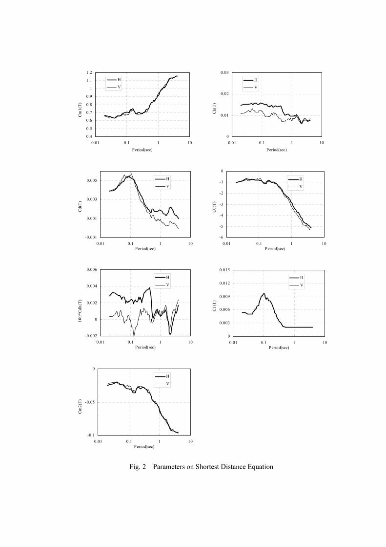
Fig. 2 Parameters on Shortest Distance Equation
Cm1(
T)
0.4
0.5
0.6
0.7
0.8
0.9
1
1.1
1.2
0.01 0.1 1 10Period(sec)
H
V
Ch(T
)
0
0.01
0.02
0.03
0.01 0.1 1 10Period(sec)
H
V
Cd(T
)
-0.001
0.001
0.003
0.005
0.01 0.1 1 10Period(sec)
H
V
C0(T
)
-6
-5
-4
-3
-2
-1
0
0.01 0.1 1 10Period(sec)
H
V
100*
Cdh(
T)
-0.002
0
0.002
0.004
0.006
0.01 0.1 1 10Period(sec)
H
V
C1(T
)
0
0.003
0.006
0.009
0.012
0.015
0.01 0.1 1 10Period(sec)
H
V
Cm2(
T)
-0.1
-0.05
0
0.01 0.1 1 10Period(sec)
H
V

Fig. 3 Parameters on Equivalent Hypocentral Distance Equation
Cm1(
T)
0.4
0.5
0.6
0.7
0.8
0.9
1
1.1
1.2
0.01 0.1 1 10Period(sec)
H
V
Ch(T
)
0
0.01
0.02
0.03
0.01 0.1 1 10Period(sec)
H
V
Cd(T
)
-0.001
0.001
0.003
0.005
0.01 0.1 1 10Period(sec)
H
V
C0(T
)
-6
-5
-4
-3
-2
-1
0
0.01 0.1 1 10Period(sec)
H
V
100*
Cdh(
T)
-0.004
-0.002
0
0.002
0.004
0.006
0.01 0.1 1 10Period(sec)
H
V
C(T)
0
10
20
30
0.01 0.1 1 10Period(sec)
H
V
Cm2(
T)
-0.2
-0.15
-0.1
-0.05
0
0.01 0.1 1 10Period(sec)
H
V

Figure 4 shows the correction factor for each type of earthquake. In this figure, the proportion of each type of earthquake in the mean earthquake motions is calculated. This figure indicates the value of the mean plus the standard deviation for the multiplying power for correction in consideration of the dispersion of earthquake motions. For the determination of Level 2 earthquake motions, the acceleration response spectrum is firstly established by inserting the parameter values for the fault surface, etc. of the Scenario Earthquake, the distance to the fault surface and the regression constant values shown in Fig. 2 and Fig. 3 to Equations (3) to (6). The acceleration response spectrum of the Scenario Earthquake is then determined by multiplying the calculated acceleration response spectrum by the correction factor for each type of earthquake shown in Fig. 4.
0
0.5
1
1.5
2
2.5
3
3.5
0.01 0.1 1 10Period(sec)
Corr
ection fac
tor
Type AType BType CType D
0
0.5
1
1.5
2
2.5
3
3.5
4
0.01 0.1 1 10Period(sec)
Cor
rect
ion
fact
or
Type AType BType CType D
0
0.5
1
1.5
2
2.5
3
3.5
0.01 0.1 1 10Period(sec)
Cor
rect
ion
fact
or
Type AType BType CType D
0
0.5
1
1.5
2
2.5
3
3.5
0.01 0.1 1 10Period(sec)
Corr
ection fac
tor
Type AType BType CType D
(a) Shortest distance equation(horizontal component) (b) Shortest distance equation(vertical component)
(c) Equivalent hypocentral distance equation(horizontal component) (d) Equivalent hypocentral distance equation(vertical component)
Fig. 4 Correction Factors for Each Type of Earthquakes
Fig. 5 Comparison of Maximum AccelerationCalculated by Shortest Distance Equation and Equivalent Hypocentral Distance Equation
0
200
400
600
800
1000
1200
1400
1600
1800
2000
2200
2400
0 200 400 600 800Maximum acceleration by shortest dintance equation
(gal)
Max
imum
acc
eler
atio
n b
y eq
uiv
alen
t hyp
oce
ntr
aleq
uat
ion (
gal)
Calculation results by the 2001FormulaCalculation results by the 2008Formula

1.4 Verification of Improved Distance Attenuation Formula for Dams
• Decrease of deviation of both the calculation
results by the shortest distance equation and equivalent hypocentral distance equation
Figure 5 shows the relationship between the maximum acceleration calculated by the shortest distance equation and equivalent hypocentral distance equation. Compared to the results between the 2001 Formula and the 2008 Formula, the overall deviation is much more compact.
• Improved compatibility for deep earthquakes
Figure 6 shows the observation data and calculation results of the distance attenuation formula for dams at the dam foundation for the Miyagiken-oki Earthquake (M7.1, Hc=77 km) occurred on May, 2003. Modification of the term expressing the distance attenuation to the term dependent on the depth of the hypocenter has improved the compatibility of the calculation results with the observation data at a dam foundation.
• Verification by comparison with dam
observation data for actual earthquakes
Figure 7 shows the horizontal maximum acceleration observed at the dam foundation during two major earthquakes and the attenuation curve of the horizontal acceleration response spectrum at the period of 0.02sec using the distance attenuation formula for dams (the 2001 and 2008 Formulas). The attenuation curves of maximum acceleration (acceleration response spectrum at the period of 0.02sec) calculated by the 2008 Formula agree well the maximum acceleration data observed at the dam foundations.
2. EVALUATION OF LOWER LIMIT ACCELERATION RESPONSE SPECTRUM FOR DAM EVALUATION
2.1 Theory for Determination of Lower Limit Acceleration Response Spectrum for Dam Evaluation
The Draft Guidelines provide “Lower-limit acceleration response spectrum for Dam evaluation” that should be considered as the mandatory minimum Level 2 earthquake motions. The reason for stipulating this minimum spectrum is that the earthquake motion used for seismic performance evaluation should be determined taking into consideration the possibility of an earthquake occurring directly at an active fault under the dam site even when no active fault is identified by the investigations. The Draft Guidelines determine the earthquake magnitude based on the following theories to prepare the lower limit acceleration response spectrum for evaluation and the same method was used for the present review. • Few earthquakes of M6.5 or smaller
produce surface earthquake faults. • Many earthquakes of M6.8 or greater
produce surface earthquake faults. • The number of earthquakes of M6.6 or M6.7
is much smaller compared to M6.5 or smaller, or, M6.8 or greater. This is not coincidental as a discontinuous scale of magnitude occurs due to the effect of the causative fault plane piercing through the ground surface.
• In exceptional cases, earthquakes exceeding M6.5 may not produce surface earthquake faults. The damage caused by these earthquakes little differs from the maximum damage caused by earthquakes of M6.5 or smaller.
• A surface earthquake fault may not be produced by earthquakes up to approximately M7.3. In the case of the Tottori-ken Seibu Earthquake (M7.3) on October, 2000, the causative fault was not identified prior to the earthquake.

Fig. 6 Comparison of Acceleration Response Spectrum (t=0.02sec) Between Observation Data and Calculation Results by Distance Attenuation Formulas for Dams in the Case of Miyagiken-oki Earthquake on May, 2003
Acc
eler
atio
n re
spon
se sp
ectru
m (g
al)
Equivalent hypocentral distance (km)
Observation data 2001 formula 2008 formula
Acc
eler
atio
n re
spon
se sp
ectru
m (g
al)
Acc
eler
atio
n re
spon
se sp
ectru
m (g
al)
Acc
eler
atio
n re
spon
se sp
ectru
m (g
al)
Acc
eler
atio
n re
spon
se sp
ectru
m (g
al)
Equivalent hypocentral distance (km) Shortest distance (km)
Equivalent hypocentral distance (km) Shortest distance (km)
(1) Niigata-ken Chuetsu-oki Earthquake in 2007 (M6.8)
(2) Iwate-Miyagi Nairiku Earthquake in 2008 (M7.2)
2001 formula(mean) 2001 formula(m±s.d.) 2008 formula(mean) 2008 formula(m±s.d) Observation data
2001 formula(mean) 2001 formula(m±s.d.) 2008 formula(mean) 2008 formula(m±s.d) Observation data
2001 formula(mean) 2001 formula(m±s.d.) 2008 formula(mean) 2008 formula(m±s.d) Observation data
2001 formula(mean) 2001 formula(m±s.d.) 2008 formula(mean) 2008 formula(m±s.d) Observation data
Fig. 7 Comparison of Maximum Acceleration (Acceleration Response Spectrum at t=0.02sec) Between Observation Data and Calculation Results by Distance Attenuation Formulas for Dams
Acc
eler
atio
n re
spon
se sp
ectru
m (g
al)
Observation data 2001 formula 2008 formula
Shortest distance (km)

The above theories descriptions are based on the JSCE Guideline of Seismic Design for Infrastructures [4] which refers to the relationships of the magnitude, damage rank and the occurrence of surface earthquake faults of past earthquakes in Japan as shown in Fig. 8. Based on the above, M6.5 and M7.3 were used to establish the lower limit acceleration response spectrum for evaluation. In the case of M6.5, it was decided to use the spectrum corresponding
to the "mean + standard deviation" in the distance attenuation formula for dams. In the case of M7.3, the "mean" of the 2008 formula was used based on the idea that the fault plane could have been identified in advance in many cases of M7.3 or greater earthquakes. Assuming the occurrence of an earthquake with the magnitude referred to above, the 2008 Formula was used to establish the acceleration response spectrum at each dam site using the locational relationship between the dam and the fault plain and the different gradients of the fault plane. 2.2 Setting of Lower Limit Acceleration
Response Spectrum for Dam Evaluation Using the method described in Section 2.1, the 84% fractile value for the earthquake with M6.5 above its epicenter was calculated using the 2008 formula (mean + standard deviation). Similarly, the 84% fractile value for the earthquake with M7.3 above its epicenter was calculated using the same equation (mean). Figure 9 shows the current lower limit acceleration response spectrum and its draft modification. The lower limit acceleration response spectrum for dam evaluation in the present Draft Guidlines found that the calculated spectra using the 2008 Formula exceed the
Fig. 8 Relations of damage rank, JMA Magnitude and the occurrence of surfaceearthquake faults.
Fig. 9 Modification of Lower Limit Acceleration Response Spectrum for Dam Evaluation (Horizontal Motions)
10
100
1000
0.01 0.1 1 10Period (sec)
Acc
eler
atio
n re
spon
se sp
ectru
m (g
al)
Lower limit acceleration response spectrum forevaluation(modified version)Lower limit acceleration response spectrum forevaluation(Draft Guidelines)M6.5, shortest distance equation(m+s.d)
M6.5, equivalent hypocentral distanceequation(m+s.d.)M7.3, shortest distance equation(mean)
M7.3, equivalent hypocentral distanceequation(mean)

current spectrum in the range of period longer than 2sec. To correct this, the long period side of the lower limit acceleration response spectrum for dam evaluation was modified to envelop the 84% fractile values of M6.5 (mean + standard deviation) and M7.3 (mean) for horizontal motions. For vertical motions, the 84% fractile values for M6.5 (mean + standard deviation) and M7.3 (mean) were calculated using the distance attenuation formula (the 2008 Formula) for vertical motion. The lower limit acceleration response spectrum for evaluation for vertical motions was set to envelop these fractile values as shown in Fig. 10. 3. CONCLUDING REMARKS Various examinations have been conducted up to the present to solve the problems discovered through the trial implementation of “Guidelines for Seismic Performance Evaluation of Dams During Large Earthquakes (Draft)”. This paper described the review of the problems associated with the distance attenuation formula of acceleration and the determination of the lower limit acceleration response spectrum for seismic evaluation of dams. Level 2 earthquake motions for the seismic
evaluation of dams were determined mainly using the distance attenuation formula for dams. In the trial implementation of the Draft Guidelines, the formula proposed in 2001 had been used but this formula caused several problems as described in this paper. Efforts were made to solve these problems by modifying the structure of the formula. At the same time, data observed during recent large earthquakes was added as regression analysis data. As a result, distance attenuation equation for horizontal motions was improved and that for vertical motions was established. Following the review of the distance attenuation formula for dams, the lower limit acceleration response spectrum for dam evaluation was also examined. The spectrum for horizontal motions was modified while the spectrum for vertical motions was newly developed. Evaluation of the seismic performance of dams in Japan will be conducted using the distance attenuation formula for dams and the lower limit acceleration response spectrum for dam evaluation described in this paper. REFERENCES 1. River Bureau, MLIT: Guidelines for Seismic
Performance Evaluation of Dams during
Fig. 10 Determination of Lower Limit Acceleration Response Spectrum for Dam Evaluation (Vertical Motions)
10
100
1000
0.01 0.1 1 10Period (sec)
Acc
eler
atio
n re
spon
se sp
ectru
m (g
al)
Lower limit acceleration response spectrum for evaluation
M6.5, shortest distance equation(m+s.d)
M6.5, equivalent hypocentral distance equation(m+s.d.)
M7.3, shortest distance equation(mean)
M7.3, equivalent hypocentral distance equation(mean)

Large Earthquakes(Draft) , 2005 2. Matsumoto, N., Ohmachi, T., Yasuda, N.,
Sasaki, T. and Annaka, T.: Acceleration Response Spectra at Dam Foundations, Proceedings of the 22nd Congress of ICOLD, 2006
3. Annaka, T., Morita, M., Aikyo, Y. and Harada, M.: An Attenuation Model for 5 % damped Acceleration Response Spectra Considering the Effect of Earthquake Type, JSCE Earthquake Engineering Symposium, 2005
4. Japan Society for Civil Engineers: Guideline of Seismic Design for Infrastructures, 2001
5. Matsumoto, N., Yoshida, H., Sasaki, T. and Annaka, T.: Response Spectra of Earthquake Motion at Dam Foundations, Proceedings of the 21st Congress of ICOLD, 2003


![Preliminary estimation of kappa (κ) in Croatia · distance. The results are important for attenuation studies [4], re-creation, and re-calibration of attenuation of peak horizontal](https://img.pdfslide.tips/doc/110x75/604d24980407664546290426/preliminary-estimation-of-kappa-in-croatia-distance-the-results-are-important.jpg)