Embed Size (px)
Citation preview
KHM 405 YS
0794 999 956 08/01 Valid for serial No. 746 - XXX - XXXX
KHM 405 YS
Bedienungs - und WartungsanleitungInstruction manualEmploi et entretien

D
KONFORMITÄTSERKLÄRUNGgemäß Richtlinie für Maschinen 98/37/EC, Niederspannungsrichtlinie 2006/95 EC,
Richtlinie EMC 2004/108/EC und Richtlinie 2000/14/EC
MaschinentypSchweißaggregat
FabrikatESAB
Bezeichnung des Produktes etc.KHM 405 YS, Code 0794 020-880 /-881 /-882 /-883ElLeistung: 12 kWGeräuschpegel: gemessen LwA 95 dB(A), garantiert LwA 96 dB(A)
KHM 405 YSX, Code 0794 020-890 /-891 /-892 /-893ElLeistung: 12 kWGeräuschpegel: gemessen LwA 93 dB(A), garantiert LwA 94 dB(A)
Gesellschaftsbezeichnung, Anschrift, Telefon- oder Telefaxnummer des Herstellers oder seinesnach den geltenden Bestimmungen autorisierten VertretersESAB AB, Welding EquipmentEsabvägen, SE-695 81 LAXÅ, SwedenPhone: +46 584 81 000, Fax: +46 584 411 924
Angewendete Normen und technische Spezifikationen:EN 60974-1, Maschinen zum Lichtbogenschweißen – Teil 1: SchweißquellenEN 12100-1, Sicherheit von Maschinen - Grundbegriffe und allgemeine Gestaltungsleitsätze - Teil 1:Grundsätzliche TerminologieEN 12100-2, Sicherheit von Maschinen - Grundbegriffe und allgemeine Gestaltungsleitsätze - Teil 2:technische LeitsätzeEN 60204-1, Sicherheit von Maschinen - Elektrische Ausrüstung von Maschinen - Teil 1: AllgemeineAnforderungenEN 60974-10, Maschinen zum Lichtbogenschweißen - Teil 10: ElektromagnetischeKompatibilitätsanforderung (EMC)EN 50081-2, Elektromagnetische Kompatibilität - Standard auf generelle Emissionen - Teil 2: IndustriekreiseEN 50082-2, Elektromagnetische Kompatibilität - generelle Standardimmunität - Teil 2: Industriekreise
Mit der Unterschrift auf diesem Dokument bestätigt der Unterzeichner als Hersteller oder alsgesetzlicher Vertreter des Herstellers, dass dieser Maschinentyp den obengenanntenSicherheitsanforderungen entspricht.
Datum Unterschrift StellungLaxå 2008-03-10 Direktor
Maschinen undAutomation
Kent EimbrodtClarification
KHM 405 YSM1
Sehr geehrter Kunde,
wir danken Ihnen, dass Sie sich für dieses Produkt entschieden haben.
Bitte lesen Sie dieses Handbuch vor Gebrauch des Aggregats aufmerksam durch.
Im Falle von Rückfragen oder Problemen wenden Sie sich bitte an das in Ihrer Nähe gelegeneServicezentrum, wo Sie fachkundig beraten werden und Original-Ersatzteile erhalten. Bei Anwendungvon Nicht-Original-Ersatzteilen verfällt jeglicher Garantieanspruch.
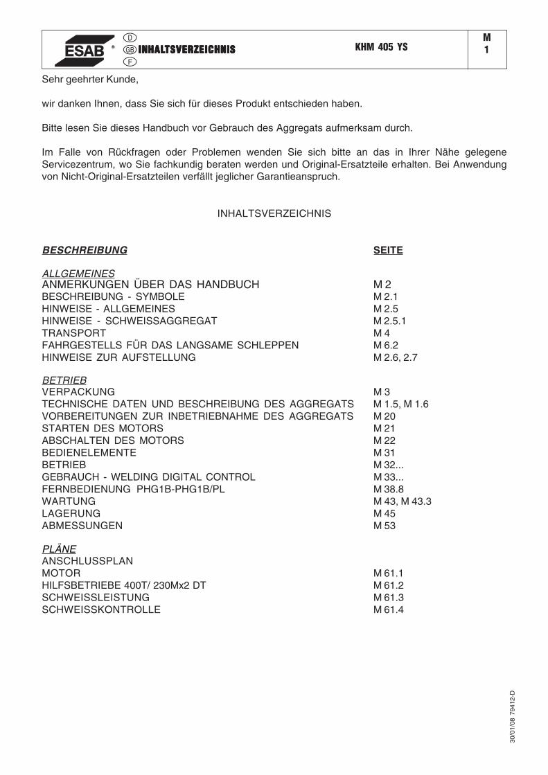
INHALTSVERZEICHNIS
BESCHREIBUNG SEITE
ALLGEMEINESANMERKUNGEN ÜBER DAS HANDBUCH M 2BESCHREIBUNG - SYMBOLE M 2.1HINWEISE - ALLGEMEINES M 2.5HINWEISE - SCHWEISSAGGREGAT M 2.5.1TRANSPORT M 4FAHRGESTELLS FÜR DAS LANGSAME SCHLEPPEN M 6.2HINWEISE ZUR AUFSTELLUNG M 2.6, 2.7
BETRIEBVERPACKUNG M 3TECHNISCHE DATEN UND BESCHREIBUNG DES AGGREGATS M 1.5, M 1.6VORBEREITUNGEN ZUR INBETRIEBNAHME DES AGGREGATS M 20STARTEN DES MOTORS M 21ABSCHALTEN DES MOTORS M 22BEDIENELEMENTE M 31BETRIEB M 32...GEBRAUCH - WELDING DIGITAL CONTROL M 33...FERNBEDIENUNG PHG1B-PHG1B/PL M 38.8WARTUNG M 43, M 43.3LAGERUNG M 45ABMESSUNGEN M 53
PLÄNEANSCHLUSSPLANMOTOR M 61.1HILFSBETRIEBE 400T/ 230Mx2 DT M 61.2SCHWEISSLEISTUNG M 61.3SCHWEISSKONTROLLE M 61.4
30/0
1/08
794
12-D
INHALINHALINHALINHALINHALTSVERZEICHNISTSVERZEICHNISTSVERZEICHNISTSVERZEICHNISTSVERZEICHNIS
��������������
�����������������
����������� ������
������� ����
����������� ���
���������������� ������
�������������� �����������������������������������
������������������������
- Die Bedienungsanleitung des Motors und der Zusatzteile (falls erforderlich) liegen diesem Handbuch in einer Plastikhülle bei. �
Das Aggregat darf nur für Schweißzwecke oder zur Erzeugung von Strom für Werkzeuge und andere angeschlossene elektrische Ausrüstungen verwendet werden. JEDER GEBRAUCH, der über die beschriebene Verwendung hinausgeht, ist nicht zulässig und enthebt unser Unternehmen von jeder Verantwortung im Falle von Körperverletzungen oder Schäden auf Grund eines unsachgemäßen Gebrauchs.
Unsere Produkte werden unter Berücksichtigung der geltenden Sicherheitsvorschriften zur Vermeidung von Körperverletzungen und Schäden am Aggregat und an Gegenständen hergestellt.
�� ���� ��������� ���� ���� ���� �!"��#$���%� &����� ��'�� ()�� ������ ���)��'������� ��*�$��+�� �'����(�*�,�����-'��������'#�'��""��&�� �.
Im Falle einer Umrüstung des Aggregats, die nicht zuvor schriftlich von unserem Unternehmen genehmigt wurde, erlischt der Garantieanspruch und enthebt uns von jeder Verantwortung.
�����������������������������
Vor der Inbetriebnahme des Aggregats ist das Handbuch aufmerksam durchzulesen. Während des Betriebs sind die darin enthaltenen Anweisungen strikt zu befolgen, damit Probleme, eventuelle Körperverletzungen und Schäden am Aggregat selbst vermieden werden.
Dieses Handbuch richtet sich an qualifizierte und auf dem Gebiet erfahrene Fachkräfte, die mit den Sicherheits- und Gesundheitsvorschriften sowie den entsprechenden Vorschriften vertraut sind.
Dieses Handbuch ist wesentlicher Bestandteil des Gerätes und demnach sorgfältig aufzubewahren, damit es bis zu dessen Entsorgung jederzeit eingesehen werden kann. Im Falle eines Weiterverkaufs ist das Handbuch dem neuen Benutzer zu übergeben.
Einige in diesem Handbuch enthaltene Abbildungen dienen dazu, einige Komponenten leichter ausfindig zu machen und könnten mit dem sich in Ihrem Besitz befindlichen Aggregat nicht übereinstimmen.
������� ���� ��� ����� � ������ �������������� ������ ���� ��� ������ �������� ����� �������������� ������� ���� ������� ����� ���������� ��������� ������ ����������� ��������!�������� ��
�������� ����� ����� "��� ��������� �� � ������������������
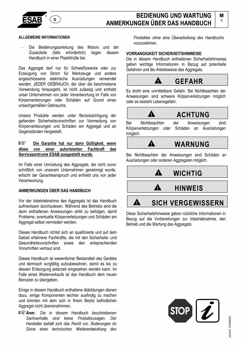
�������������������������� �����Die in diesem Handbuch enthaltenen Sicherheitshinweise geben wichtige Informationen in Bezug auf potentielle Gefahren und die Arbeitsweise des Aggregats.
Es droht eine unmittelbare Gefahr. Bei Nichtbeachten der Anweisungen sind schwere Körperverletzungen möglich oder es besteht Lebensgefahr.
Bei Nichtbeachten der Anweisungen sind Körperverletzungen oder Schäden an Ausrüstungen möglich.
Bei Nichtbeachten der Anweisungen sind Schäden an Ausrüstungen oder anderen Aggregaten möglich.
Diese Sicherheitshinweise geben nützliche Informationen in Bezug auf die Vorbereitungen zur Inbetriebnahme, den Betrieb und die Wartung des Aggregats.
�2���
22
/8/0
0
ES
AB
M2
D
������������� ��
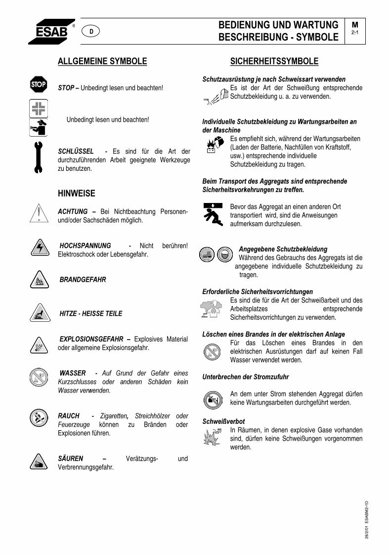
�����Unbedingt lesen und beachten!
Unbedingt lesen und beachten!
��� ����� � �� Es sind für die Art der durchzuführenden Arbeit geeignete Werkzeuge zu benutzen.
�������
������� � Bei Nichtbeachtung Personen- und/oder Sachschäden möglich.
������������ � � Nicht berühren! Elektroschock oder Lebensgefahr.����������������
�������������������������
����������������� �� Explosives Material oder allgemeine Explosionsgefahr. ���������� � �� #�$� %���� ��� %�$ ��� �����&��������� ���� ������ ������� ����� ������!����.�������� � �� '�� �������� ��������(����� ����)���������� können zu Bränden oder Explosionen führen. �
������� �� Verätzungs- und Verbrennungsgefahr.
���
������������ ������ !"# $%&$! �'�()��#������*)+$$#%!�,)%*)�-)��
Es ist der Art der Schweißung entsprechende Schutzbekleidung u. a. zu verwenden.
����-+,+- )..)���� !"/)0.)+- �'�" ��#%! �'$#%/)+!)��#��-)%�1#$��+�)�
Es empfiehlt sich, während der Wartungsarbeiten (Laden der Batterie, Nachfüllen von Kraftstoff, usw.) entsprechende individuelle Schutzbekleidung zu tragen.
�)+���%#�$23%!�-)$��''%)'#!$�$+�-�)�!$2%)��)�-)��+��)%�)+!$,3%0)�% �')��" �!%)44)�5���
Bevor das Aggregat an einen anderen Ort transportiert wird, sind die Anweisungen aufmerksam durchzulesen.
��
��')')/)�)���� !"/)0.)+- �'�Während des Gebrauchs des Aggregats ist die
angegebene individuelle Schutzbekleidung zu tragen.
�%43%-)%.+��)��+��)%�)+!$,3%%+��! �')��Es sind die für die Art der Schweißarbeit und des Arbeitsplatzes entsprechende Sicherheitsvorrichtungen zu verwenden.
�6$��)��)+�)$��%#�-)$�+��-)%�).)0!%+$��)����.#')�Für das Löschen eines Brandes in den elektrischen Ausrüstungen darf auf keinen Fall Wasser verwendet werden.
��!)%/%)��)��-)%��!%3�" 4 �%��
An dem unter Strom stehenden Aggregat dürfen keine Wartungsarbeiten durchgeführt werden.
���*)+7,)%/3!
In Räumen, in denen explosive Gase vorhanden sind, dürfen keine Schweißungen vorgenommen werden.
26
/2/0
1
ES
AB
M2
-1D
���������������������������������� ��
�2.1�
���������������������������������������������������1�����������������5��
���������
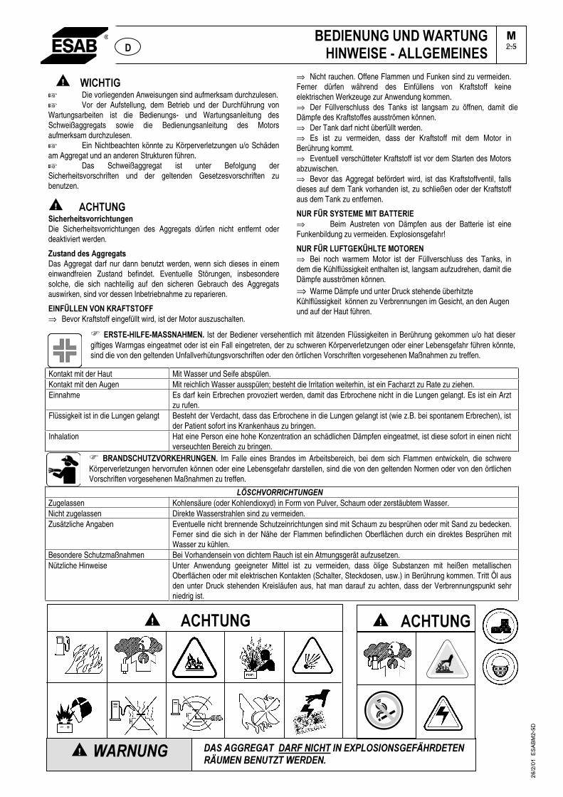
� ���������� Die vorliegenden Anweisungen sind aufmerksam durchzulesen. �� Vor der Aufstellung, dem Betrieb und der Durchführung von Wartungsarbeiten ist die Bedienungs- und Wartungsanleitung des Schweißaggregats sowie die Bedienungsanleitung des Motors aufmerksam durchzulesen. �� Ein Nichtbeachten könnte zu Körperverletzungen u/o Schäden am Aggregat und an anderen Strukturen führen. � Das Schweißaggregat ist unter Befolgung der Sicherheitsvorschriften und der geltenden Gesetzesvorschriften zu benutzen.
������������ ������ ������ ����������Die Sicherheitsvorrichtungen des Aggregats dürfen nicht entfernt oder deaktiviert werden.
����������������������Das Aggregat darf nur dann benutzt werden, wenn sich dieses in einem einwandfreien Zustand befindet. Eventuelle Störungen, insbesondere solche, die sich nachteilig auf den sicheren Gebrauch des Aggregats auswirken, sind vor dessen Inbetriebnahme zu reparieren.
���������� !��"#����!���⇒ Bevor Kraftstoff eingefüllt wird, ist der Motor auszuschalten.
⇒ Nicht rauchen. Offene Flammen und Funken sind zu vermeiden. Ferner dürfen während des Einfüllens von Kraftstoff keine elektrischen Werkzeuge zur Anwendung kommen. ⇒ Der Füllverschluss des Tanks ist langsam zu öffnen, damit die Dämpfe des Kraftstoffes ausströmen können. ⇒ Der Tank darf nicht überfüllt werden. ⇒ Es ist zu vermeiden, dass der Kraftstoff mit dem Motor in Berührung kommt. ⇒ Eventuell verschütteter Kraftstoff ist vor dem Starten des Motors abzuwischen. ⇒ Bevor das Aggregat befördert wird, ist das Kraftstoffventil, falls dieses auf dem Tank vorhanden ist, zu schließen oder der Kraftstoff aus dem Tank zu entfernen.
�#���#��$���%��%���&���#���⇒ Beim Austreten von Dämpfen aus der Batterie ist eine Funkenbildung zu vermeiden. Explosionsgefahr!
�#���#������"������%!�!#���⇒ Bei noch warmem Motor ist der Füllverschluss des Tanks, in dem die Kühlflüssigkeit enthalten ist, langsam aufzudrehen, damit die Dämpfe ausströmen können. ⇒ Warme Dämpfe und unter Druck stehende überhitzte Kühlflüssigkeit können zu Verbrennungen im Gesicht, an den Augen und auf der Haut führen.
���#���'�����'%����%��( Ist der Bediener versehentlich mit ätzenden Flüssigkeiten in Berührung gekommen u/o hat dieser giftiges Warmgas eingeatmet oder ist ein Fall eingetreten, der zu schweren Körperverletzungen oder einer Lebensgefahr führen könnte,sind die von den geltenden Unfallverhütungsvorschriften oder den örtlichen Vorschriften vorgesehenen Maßnahmen zu treffen.
Kontakt mit der Haut Mit Wasser und Seife abspülen. Kontakt mit den Augen Mit reichlich Wasser ausspülen; besteht die Irritation weiterhin, ist ein Facharzt zu Rate zu ziehen. Einnahme Es darf kein Erbrechen provoziert werden, damit das Erbrochene nicht in die Lungen gelangt. Es ist ein Arzt
zu rufen. Flüssigkeit ist in die Lungen gelangt Besteht der Verdacht, dass das Erbrochene in die Lungen gelangt ist (wie z.B. bei spontanem Erbrechen), ist
der Patient sofort ins Krankenhaus zu bringen. Inhalation Hat eine Person eine hohe Konzentration an schädlichen Dämpfen eingeatmet, ist diese sofort in einen nicht
verseuchten Bereich zu bringen. �� &#�)����� !#"��#����( Im Falle eines Brandes im Arbeitsbereich, bei dem sich Flammen entwickeln, die schwere Körperverletzungen hervorrufen können oder eine Lebensgefahr darstellen, sind die von den geltenden Normen oder von den örtlichenVorschriften vorgesehenen Maßnahmen zu treffen.
�8��9������������Zugelassen Kohlensäure (oder Kohlendioxyd) in Form von Pulver, Schaum oder zerstäubtem Wasser. Nicht zugelassen Direkte Wasserstrahlen sind zu vermeiden. Zusätzliche Angaben Eventuelle nicht brennende Schutzeinrichtungen sind mit Schaum zu besprühen oder mit Sand zu bedecken.
Ferner sind die sich in der Nähe der Flammen befindlichen Oberflächen durch ein direktes Besprühen mit Wasser zu kühlen.
Besondere Schutzmaßnahmen Bei Vorhandensein von dichtem Rauch ist ein Atmungsgerät aufzusetzen. Nützliche Hinweise Unter Anwendung geeigneter Mittel ist zu vermeiden, dass ölige Substanzen mit heißen metallischen
Oberflächen oder mit elektrischen Kontakten (Schalter, Steckdosen, usw.) in Berührung kommen. Tritt Öl aus den unter Druck stehenden Kreisläufen aus, hat man darauf zu achten, dass der Verbrennungspunkt sehr niedrig ist.
26
/2/0
1
ES
AB
M2
-5D
� ������������������
&�)�������)��#�������������'�����%������
�2.5)�
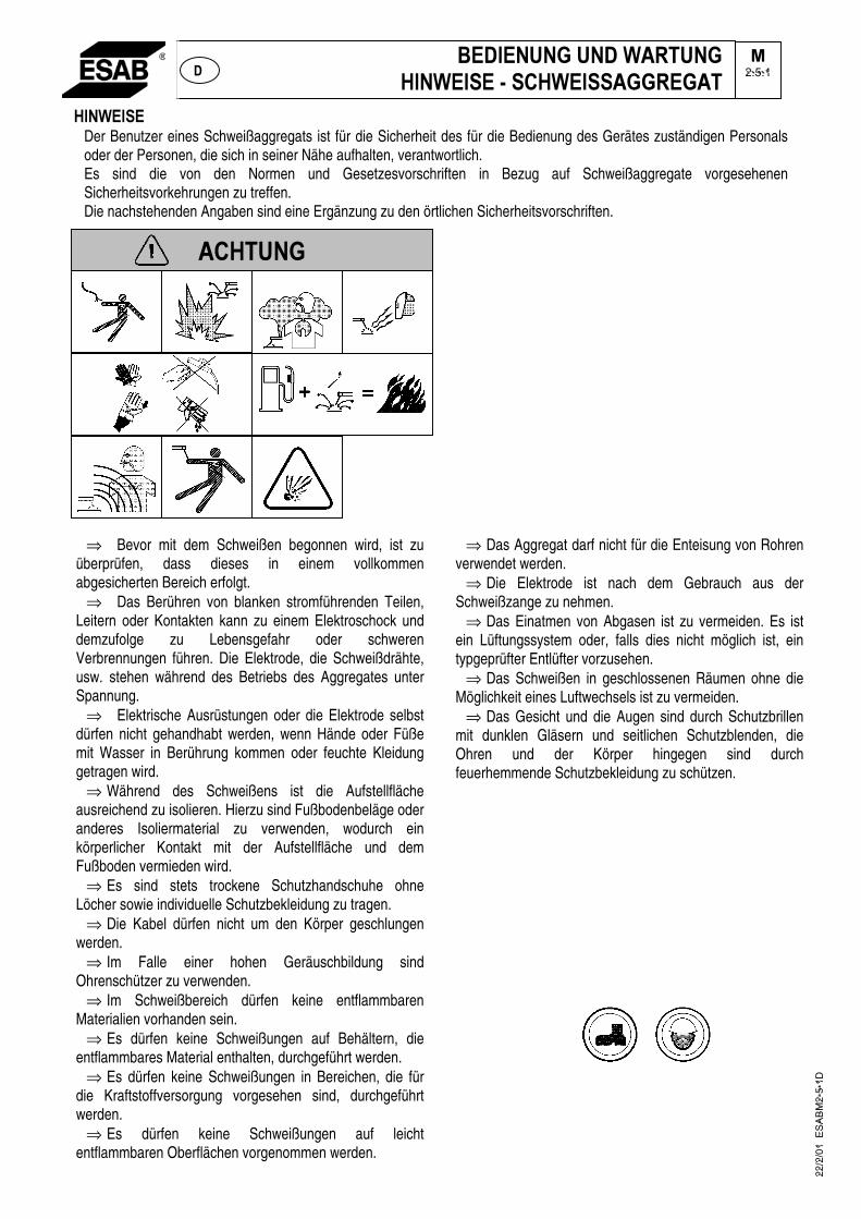
���������Der Benutzer eines Schweißaggregats ist für die Sicherheit des für die Bedienung des Gerätes zuständigen Personals oder der Personen, die sich in seiner Nähe aufhalten, verantwortlich. Es sind die von den Normen und Gesetzesvorschriften in Bezug auf Schweißaggregate vorgesehenen Sicherheitsvorkehrungen zu treffen. Die nachstehenden Angaben sind eine Ergänzung zu den örtlichen Sicherheitsvorschriften.
⇒ Bevor mit dem Schweißen begonnen wird, ist zu überprüfen, dass dieses in einem vollkommen abgesicherten Bereich erfolgt.
⇒ Das Berühren von blanken stromführenden Teilen, Leitern oder Kontakten kann zu einem Elektroschock und demzufolge zu Lebensgefahr oder schweren Verbrennungen führen. Die Elektrode, die Schweißdrähte, usw. stehen während des Betriebs des Aggregates unter Spannung.
⇒ Elektrische Ausrüstungen oder die Elektrode selbst dürfen nicht gehandhabt werden, wenn Hände oder Füße mit Wasser in Berührung kommen oder feuchte Kleidung getragen wird.
⇒ Während des Schweißens ist die Aufstellfläche ausreichend zu isolieren. Hierzu sind Fußbodenbeläge oder anderes Isoliermaterial zu verwenden, wodurch ein körperlicher Kontakt mit der Aufstellfläche und dem Fußboden vermieden wird.
⇒ Es sind stets trockene Schutzhandschuhe ohne Löcher sowie individuelle Schutzbekleidung zu tragen.
⇒ Die Kabel dürfen nicht um den Körper geschlungen werden.
⇒ Im Falle einer hohen Geräuschbildung sind Ohrenschützer zu verwenden.
⇒ Im Schweißbereich dürfen keine entflammbaren Materialien vorhanden sein.
⇒ Es dürfen keine Schweißungen auf Behältern, die entflammbares Material enthalten, durchgeführt werden.
⇒ Es dürfen keine Schweißungen in Bereichen, die für die Kraftstoffversorgung vorgesehen sind, durchgeführt werden.
⇒ Es dürfen keine Schweißungen auf leicht entflammbaren Oberflächen vorgenommen werden.
⇒ Das Aggregat darf nicht für die Enteisung von Rohren verwendet werden.
⇒ Die Elektrode ist nach dem Gebrauch aus der Schweißzange zu nehmen.
⇒ Das Einatmen von Abgasen ist zu vermeiden. Es ist ein Lüftungssystem oder, falls dies nicht möglich ist, ein typgeprüfter Entlüfter vorzusehen.
⇒ Das Schweißen in geschlossenen Räumen ohne die Möglichkeit eines Luftwechsels ist zu vermeiden.
⇒ Das Gesicht und die Augen sind durch Schutzbrillen mit dunklen Gläsern und seitlichen Schutzblenden, die Ohren und der Körper hingegen sind durch feuerhemmende Schutzbekleidung zu schützen.
������������ ������������������������� ����� ��
������
���
2.5.1
22/2
/01
ES
AB
M2-
5-1D
��������������������
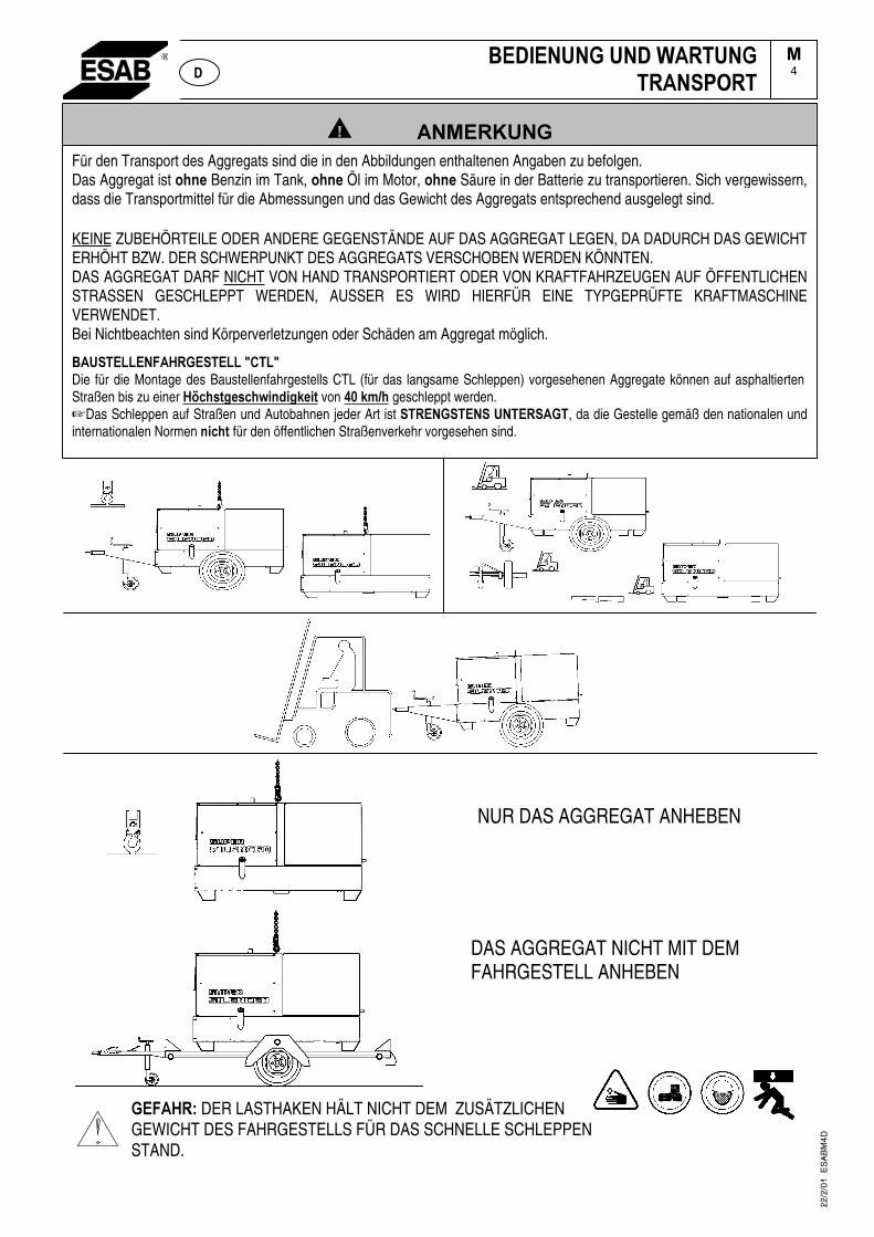
NUR DAS AGGREGAT ANHEBEN
�DAS AGGREGAT NICHT MIT DEM FAHRGESTELL ANHEBEN
�������DER LASTHAKEN HÄLT NICHT DEM ZUSÄTZLICHEN GEWICHT DES FAHRGESTELLS FÜR DAS SCHNELLE SCHLEPPEN STAND.
���� � ��� ������� ����� ������
��4
Für den Transport des Aggregats sind die in den Abbildungen enthaltenen Angaben zu befolgen. Das Aggregat ist �����Benzin im Tank, ���� Öl im Motor, ���� Säure in der Batterie zu transportieren. Sich vergewissern, dass die Transportmittel für die Abmessungen und das Gewicht des Aggregats entsprechend ausgelegt sind.
KEINE ZUBEHÖRTEILE ODER ANDERE GEGENSTÄNDE AUF DAS AGGREGAT LEGEN, DA DADURCH DAS GEWICHT ERHÖHT BZW. DER SCHWERPUNKT DES AGGREGATS VERSCHOBEN WERDEN KÖNNTEN. DAS AGGREGAT DARF NICHT VON HAND TRANSPORTIERT ODER VON KRAFTFAHRZEUGEN AUF ÖFFENTLICHEN STRASSEN GESCHLEPPT WERDEN, AUSSER ES WIRD HIERFÜR EINE TYPGEPRÜFTE KRAFTMASCHINE VERWENDET.Bei Nichtbeachten sind Körperverletzungen oder Schäden am Aggregat möglich.
�������� ������������������Die für die Montage des Baustellenfahrgestells CTL (für das langsame Schleppen) vorgesehenen Aggregate können auf asphaltierten Straßen bis zu einer ����������� !�"!�#�!� von $%�#&'� geschleppt werden. ☞Das Schleppen auf Straßen und Autobahnen jeder Art ist ���� ���� ��� �������, da die Gestelle�gemäß den nationalen und internationalen Normen �!����für den öffentlichen Straßenverkehr vorgesehen sind.
22
/2/0
1
ES
AB
M4
D
���
MONTAGE DES FAHRGESTELLS FÜR DAS LANGSAME SCHLEPPEN FÜRKHM 351 YS BCKHM 405 YS
M6.2
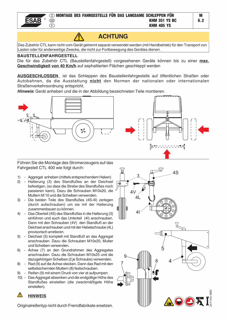
Hinweis: Gerät anheben und die in der Abbildung bezeichneten Teile montieren.
Das Zubehör CTL kann nicht vom Gerät getrennt separat verwendet werden (mit Handbetrieb) für den Transport vonLasten oder für anderweitige Zwecke, die nicht zur Fortbewegung des Gerätes dienen.
Führen Sie die Montage des Stromerzeugers auf dasFahrgestell CTL 400 wie folgt durch:
1) - Aggregat anheben (mittels entsprechendem Haken)2) - Halterung (3) des Standfußes an der Deichsel
befestigen, (so dass die Strebe des Standfußes nochpassieren kann). Dazu die Schrauben M10x20, dieMuttern M 10 und die Scheiben verwenden.
3) - Die beiden Teile des Standfußes (4S-4I) zerlegen(durch aufschrauben) um sie mit der Halterungzusammenbauen zu können.
4) - Das Oberteil (4S) des Standfußes in die Halterung (3)einführen und auch das Unterteil (4I) anschrauben.Dann mit den Schrauben (4V) den Standfuß an derDeichsel anschrauben und mit der Hebelschraube (4L)provisorisch arretieren.
5) - Deichsel (5) komplett mit Standfuß an das Aggregatanschrauben. Dazu die Schrauben M10x20, Mutterund Scheiben verwenden.
6) - Achse (7) an den Grundrahmen des Aggregatesanschrauben. Dazu die Schrauben M10x25 und diedazugehörigen Scheiben (2 je Schraube) verwenden.
8) - Rad (9) auf die Achse stecken. Dann das Rad mit denselbstsichernden Muttern (8) festschrauben.
9) - Reifen (9) mit einem Druck von vier at aufpumpen.10) - Das Aggregat absenken und die endgültige Höhe des
Standfußes einstellen (die zweckmäßigste Höheeinstellen).
HINWEIS
Originalreifentyp nicht durch Fremdfabrikate ersetzen.
ACHTUNG
4
5
34S
4I
4L
4V
78
9
BAUSTELLENFAHRGESTELLDie für das Zubehör CTL (Baustellenfahrgestell) vorgesehenen Geräte können bis zu einer max.Geschwindigkeit von 40 Km/h auf asphaltierten Flächen geschleppt werden
AUSGESCHLOSSEN ist das Schleppen des Baustellenfahrgestells auf öffentlichen Straßen oderAutobahnen, da die Ausstattung nicht den Normen der nationalen oder internationalenStraßenverkehrsordnung entspricht.
24/1
1/03
M6D
��������������������������
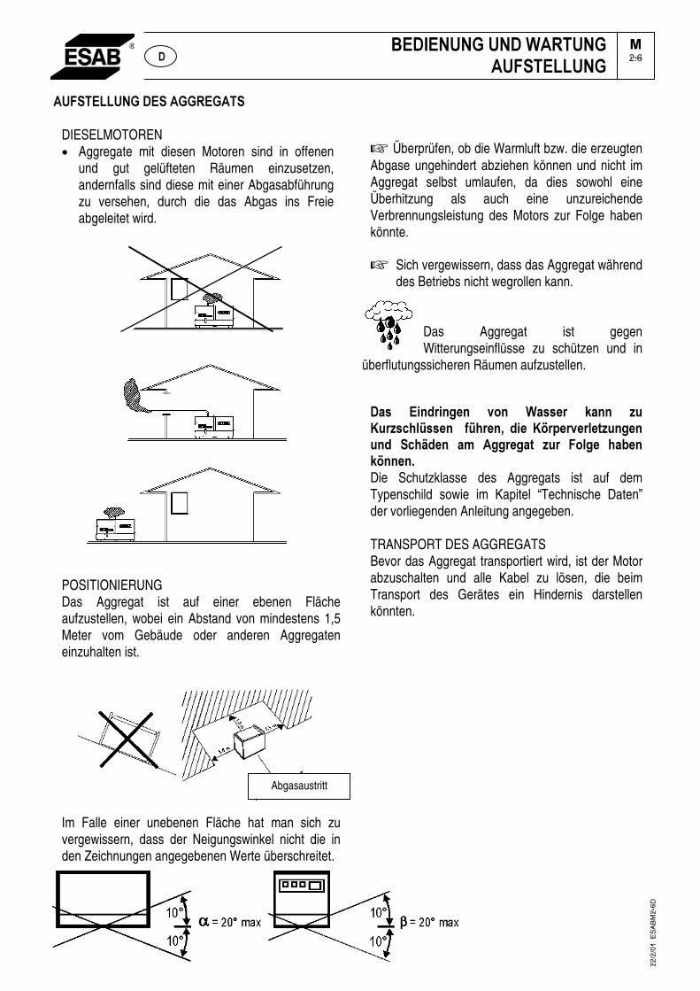
DIESELMOTOREN • Aggregate mit diesen Motoren sind in offenen
und gut gelüfteten Räumen einzusetzen, andernfalls sind diese mit einer Abgasabführung zu versehen, durch die das Abgas ins Freie abgeleitet wird.
POSITIONIERUNG Das Aggregat ist auf einer ebenen Fläche aufzustellen, wobei ein Abstand von mindestens 1,5 Meter vom Gebäude oder anderen Aggregaten einzuhalten ist.
Im Falle einer unebenen Fläche hat man sich zu vergewissern, dass der Neigungswinkel nicht die in den Zeichnungen angegebenen Werte überschreitet.
� Überprüfen, ob die Warmluft bzw. die erzeugten Abgase ungehindert abziehen können und nicht im Aggregat selbst umlaufen, da dies sowohl eine Überhitzung als auch eine unzureichende Verbrennungsleistung des Motors zur Folge haben könnte.
�� Sich vergewissern, dass das Aggregat während des Betriebs nicht wegrollen kann.
Das Aggregat ist gegen Witterungseinflüsse zu schützen und in
überflutungssicheren Räumen aufzustellen.�
���� ����������� ���� ������� ����� � �! ���"#$%����� � &%#���'� ���� !(�)�����$�*� ����� ��� �"#+���� �,� �������*� � �� ��$��� #�-����(����.�Die Schutzklasse des Aggregats ist auf dem Typenschild sowie im Kapitel “Technische Daten” der vorliegenden Anleitung angegeben.
TRANSPORT DES AGGREGATS Bevor das Aggregat transportiert wird, ist der Motor abzuschalten und alle Kabel zu lösen, die beim Transport des Gerätes ein Hindernis darstellen könnten.
���������������������������������
�2.6����
Abgasaustritt
22
/2/0
1
ES
AB
M2
-6D

InstallazioneInstallationInstallation
KHM 405 YSM
2.7
KHM 405 YS
30/0
1/08
794
12-G
B
������������ �
���*����������������
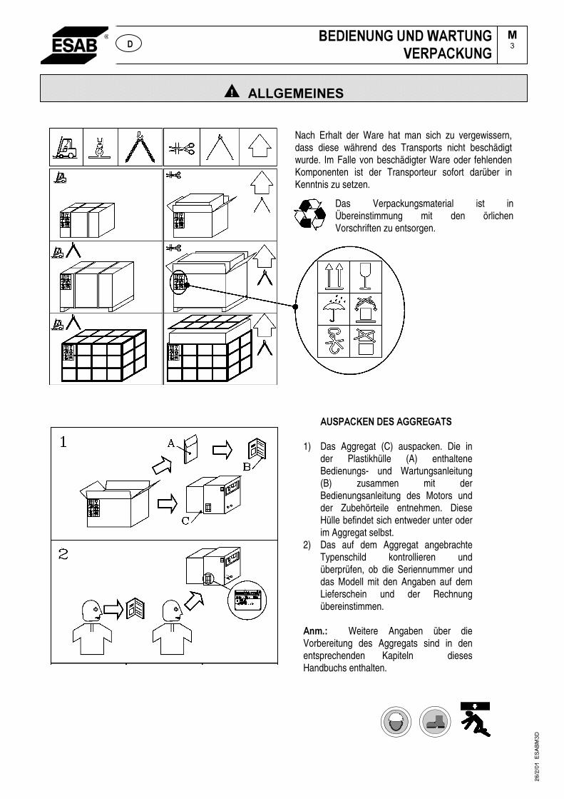
1) Das Aggregat (C) auspacken. Die in der Plastikhülle (A) enthaltene Bedienungs- und Wartungsanleitung (B) zusammen mit der Bedienungsanleitung des Motors und der Zubehörteile entnehmen. Diese Hülle befindet sich entweder unter oder im Aggregat selbst.
2) Das auf dem Aggregat angebrachte Typenschild kontrollieren und überprüfen, ob die Seriennummer und das Modell mit den Angaben auf dem Lieferschein und der Rechnung übereinstimmen.
� +�, Weitere Angaben über die Vorbereitung des Aggregats sind in den entsprechenden Kapiteln dieses Handbuchs enthalten.
��� �
26
/2/0
1
ES
AB
M3
D
Nach Erhalt der Ware hat man sich zu vergewissern, dass diese während des Transports nicht beschädigt wurde. Im Falle von beschädigter Ware oder fehlenden Komponenten ist der Transporteur sofort darüber in Kenntnis zu setzen.
Das Verpackungsmaterial ist in Übereinstimmung mit den örlichen Vorschriften zu entsorgen.
���������������������*�����
��3���
KHM 405 YSM
1.5
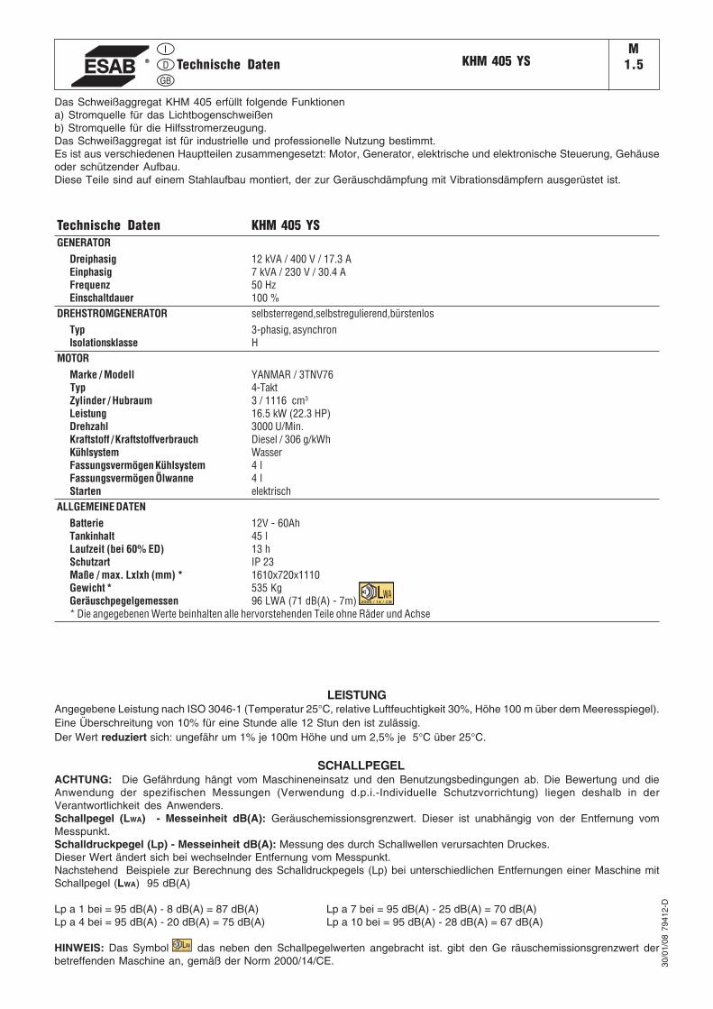
Das Schweißaggregat KHM 405 erfüllt folgende Funktionena) Stromquelle für das Lichtbogenschweißenb) Stromquelle für die Hilfsstromerzeugung.Das Schweißaggregat ist für industrielle und professionelle Nutzung bestimmt.Es ist aus verschiedenen Hauptteilen zusammengesetzt: Motor, Generator, elektrische und elektronische Steuerung, Gehäuseoder schützender Aufbau.Diese Teile sind auf einem Stahlaufbau montiert, der zur Geräuschdämpfung mit Vibrationsdämpfern ausgerüstet ist.
Technische Daten KHM 405 YSGENERATOR
Dreiphasig 12 kVA / 400 V / 17.3 AEinphasig 7 kVA / 230 V / 30.4 AFrequenz 50 HzEinschaltdauer 100 %
DREHSTROMGENERATOR selbsterregend,selbstregulierend,bürstenlosTyp 3-phasig, asynchronIsolationsklasse H
MOTORMarke / Modell YANMAR / 3TNV76
Typ 4-TaktZylinder / Hubraum 3 / 1116 cm3
Leistung 16.5 kW (22.3 HP)Drehzahl 3000 U/Min.Kraftstoff / Kraftstoffverbrauch Diesel / 306 g/kWhKühlsystem WasserFassungsvermögen Kühlsystem 4 lFassungsvermögen Ölwanne 4 lStarten elektrisch
ALLGEMEINE DATENBatterie 12V - 60AhTankinhalt 45 lLaufzeit (bei 60% ED) 13 hSchutzart IP 23Maße / max. Lxlxh (mm) * 1610x720x1110Gewicht * 535 KgGeräuschpegelgemessen 96 LWA (71 dB(A) - 7m)* Die angegebenen Werte beinhalten alle hervorstehenden Teile ohne Räder und Achse
30/0
1/08
794
12-D
LEISTUNGAngegebene Leistung nach ISO 3046-1 (Temperatur 25°C, relative Luftfeuchtigkeit 30%, Höhe 100 m über dem Meeresspiegel).Eine Überschreitung von 10% für eine Stunde alle 12 Stun den ist zulässig.Der Wert reduziert sich: ungefähr um 1% je 100m Höhe und um 2,5% je 5°C über 25°C.
SCHALLPEGELACHTUNG: Die Gefährdung hängt vom Maschineneinsatz und den Benutzungsbedingungen ab. Die Bewertung und dieAnwendung der spezifischen Messungen (Verwendung d.p.i.-Individuelle Schutzvorrichtung) liegen deshalb in derVerantwortlichkeit des Anwenders.Schallpegel (LWA) - Messeinheit dB(A): Geräuschemissionsgrenzwert. Dieser ist unabhängig von der Entfernung vomMesspunkt.Schalldruckpegel (Lp) - Messeinheit dB(A): Messung des durch Schallwellen verursachten Druckes.Dieser Wert ändert sich bei wechselnder Entfernung vom Messpunkt.Nachstehend Beispiele zur Berechnung des Schalldruckpegels (Lp) bei unterschiedlichen Entfernungen einer Maschine mitSchallpegel (LWA) 95 dB(A)
Lp a 1 bei = 95 dB(A) - 8 dB(A) = 87 dB(A) Lp a 7 bei = 95 dB(A) - 25 dB(A) = 70 dB(A)Lp a 4 bei = 95 dB(A) - 20 dB(A) = 75 dB(A) Lp a 10 bei = 95 dB(A) - 28 dB(A) = 67 dB(A)
HINWEIS: Das Symbol das neben den Schallpegelwerten angebracht ist. gibt den Ge räuschemissionsgrenzwert derbetreffenden Maschine an, gemäß der Norm 2000/14/CE.
2000 / 14 / CE
2000 / 14 / CE
Technische Daten
KHM 405 YSM
1.6
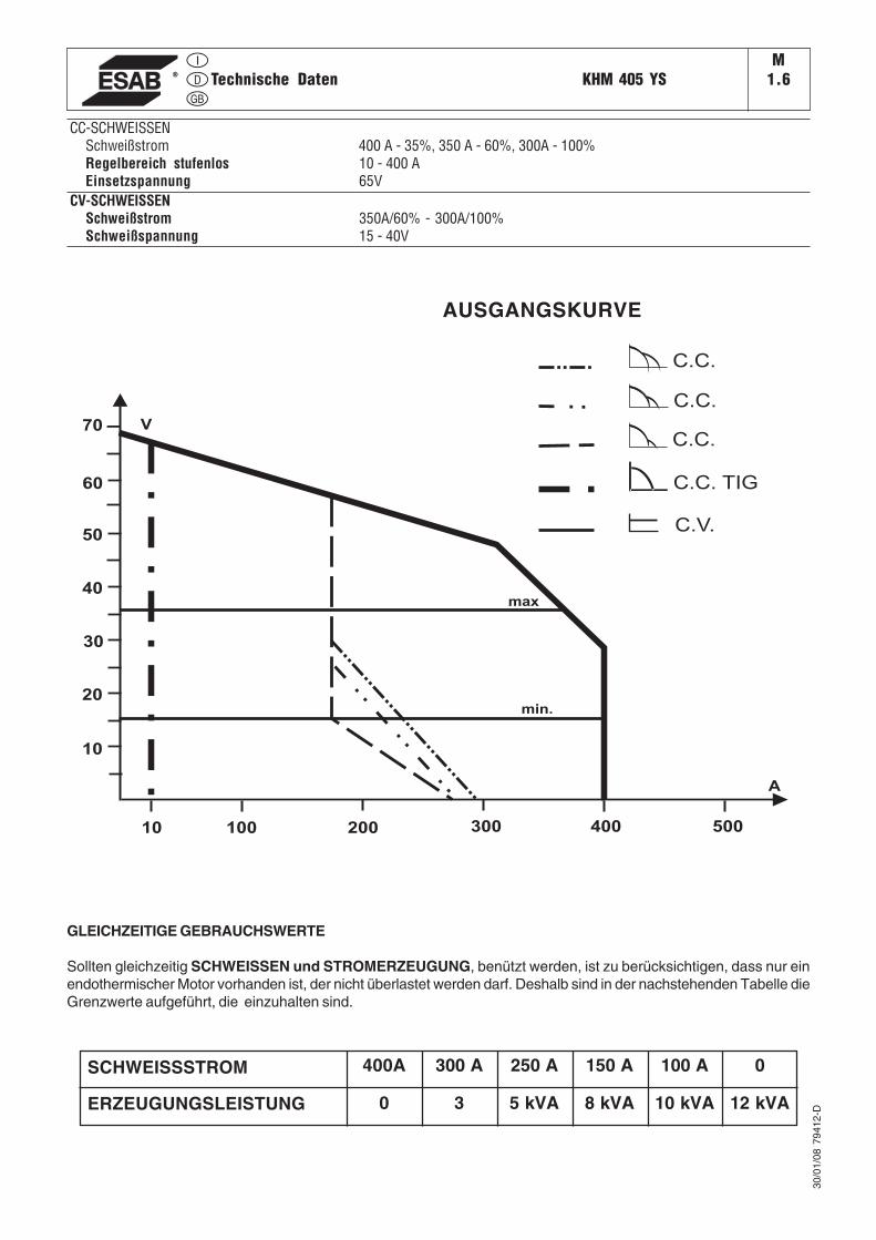
CC-SCHWEISSENSchweißstrom 400 A - 35%, 350 A - 60%, 300A - 100%Regelbereich stufenlos 10 - 400 AEinsetzspannung 65V
CV-SCHWEISSENSchweißstrom 350A/60% - 300A/100%Schweißspannung 15 - 40V
30/0
1/08
794
12-D
GLEICHZEITIGE GEBRAUCHSWERTE
Sollten gleichzeitig SCHWEISSEN und STROMERZEUGUNG, benützt werden, ist zu berücksichtigen, dass nur einendothermischer Motor vorhanden ist, der nicht überlastet werden darf. Deshalb sind in der nachstehenden Tabelle dieGrenzwerte aufgeführt, die einzuhalten sind.
8 kVA5 kVA30ERZEUGUNGSLEISTUNG
250 A300 A400ASCHWEISSSTROM 0150 A 100 A
10 kVA 12 kVA
100 200 300 400 500
A
V
10
20
30
40
50
60
70
10
min.
max
C.V.
C.C. TIG
C.C.
C.C.
C.C.
Technische Daten
AUSGANGSKURVE
BATTERIE OHNE WARTUNG
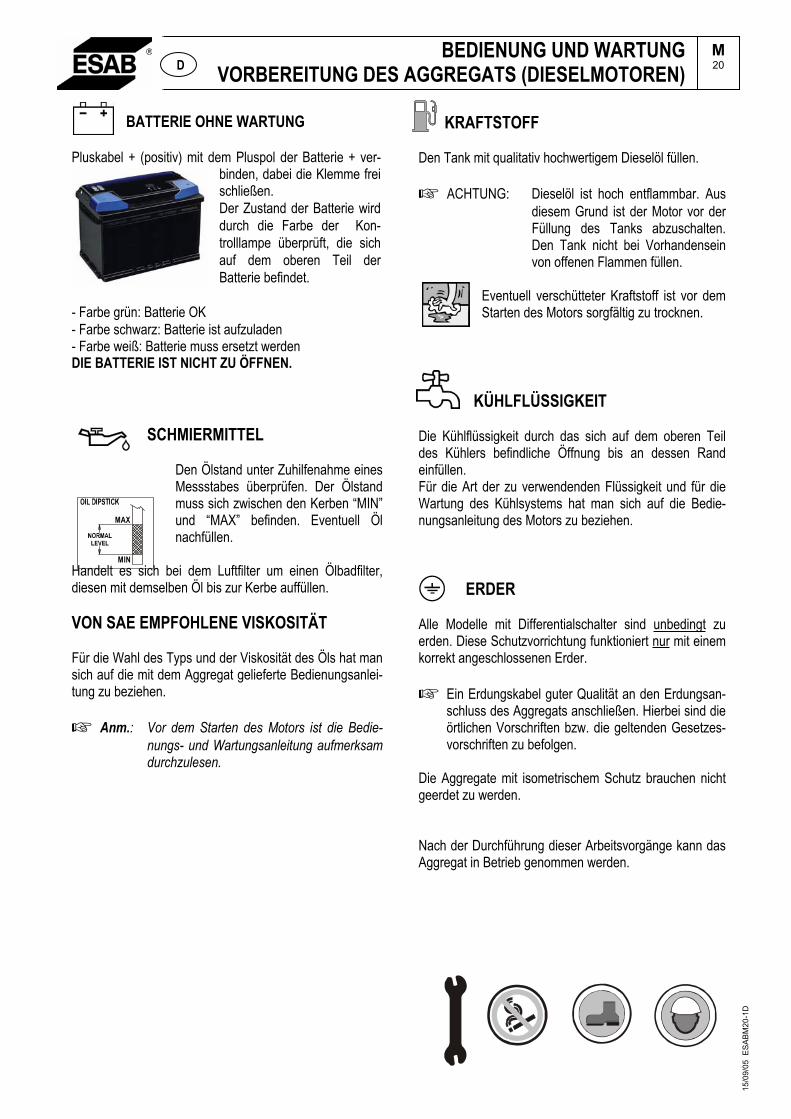
Pluskabel + (positiv) mit dem Pluspol der Batterie + ver-binden, dabei die Klemme frei schließen.Der Zustand der Batterie wird durch die Farbe der Kon-trolllampe überprüft, die sich auf dem oberen Teil der Batterie befindet.
- Farbe grün: Batterie OK - Farbe schwarz: Batterie ist aufzuladen - Farbe weiß: Batterie muss ersetzt werden DIE BATTERIE IST NICHT ZU ÖFFNEN.
SCHMIERMITTEL
Den Ölstand unter Zuhilfenahme eines Messstabes überprüfen. Der Ölstand muss sich zwischen den Kerben “MIN” und “MAX” befinden. Eventuell Öl nachfüllen.
Handelt es sich bei dem Luftfilter um einen Ölbadfilter, diesen mit demselben Öl bis zur Kerbe auffüllen.
VON SAE EMPFOHLENE VISKOSITÄT
Für die Wahl des Typs und der Viskosität des Öls hat man sich auf die mit dem Aggregat gelieferte Bedienungsanlei-tung zu beziehen.
Anm.: Vor dem Starten des Motors ist die Bedie-nungs- und Wartungsanleitung aufmerksam durchzulesen.
KRAFTSTOFF
Den Tank mit qualitativ hochwertigem Dieselöl füllen.
ACHTUNG: Dieselöl ist hoch entflammbar. Aus diesem Grund ist der Motor vor der Füllung des Tanks abzuschalten. Den Tank nicht bei Vorhandensein von offenen Flammen füllen.
Eventuell verschütteter Kraftstoff ist vor dem Starten des Motors sorgfältig zu trocknen.
KÜHLFLÜSSIGKEIT
Die Kühlflüssigkeit durch das sich auf dem oberen Teil des Kühlers befindliche Öffnung bis an dessen Rand einfüllen.Für die Art der zu verwendenden Flüssigkeit und für die Wartung des Kühlsystems hat man sich auf die Bedie-nungsanleitung des Motors zu beziehen.
ERDER
Alle Modelle mit Differentialschalter sind unbedingt zu erden. Diese Schutzvorrichtung funktioniert nur mit einem korrekt angeschlossenen Erder.
Ein Erdungskabel guter Qualität an den Erdungsan-schluss des Aggregats anschließen. Hierbei sind die örtlichen Vorschriften bzw. die geltenden Gesetzes-vorschriften zu befolgen.
Die Aggregate mit isometrischem Schutz brauchen nicht geerdet zu werden.
Nach der Durchführung dieser Arbeitsvorgänge kann das Aggregat in Betrieb genommen werden.
BEDIENUNG UND WARTUNGVORBEREITUNG DES AGGREGATS (DIESELMOTOREN)
M20 D
MAX
MIN
15/0
9/05
ES
AB
M20
-1D
Motorstart KHM 351 YSKHM 405 YSX
M21
12/1
1/07
773
85-D
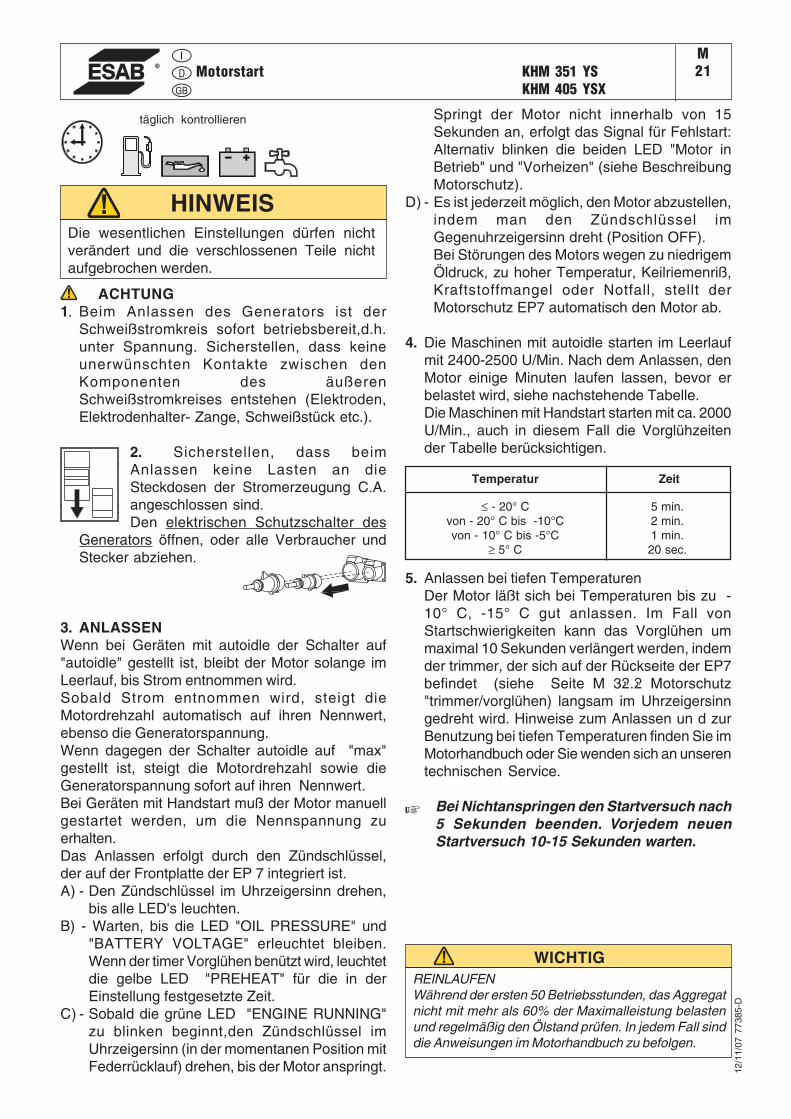
Die wesentlichen Einstellungen dürfen nichtverändert und die verschlossenen Teile nichtaufgebrochen werden.
HINWEIS
ACHTUNG1. Beim Anlassen des Generators ist der
Schweißstromkreis sofort betriebsbereit,d.h.unter Spannung. Sicherstellen, dass keineunerwünschten Kontakte zwischen denKomponenten des äußerenSchweißstromkreises entstehen (Elektroden,Elektrodenhalter- Zange, Schweißstück etc.).
2. Sicherstellen, dass beimAnlassen keine Lasten an dieSteckdosen der Stromerzeugung C.A.angeschlossen sind.Den elektrischen Schutzschalter des
Generators öffnen, oder alle Verbraucher undStecker abziehen.
3. ANLASSENWenn bei Geräten mit autoidle der Schalter auf"autoidle" gestellt ist, bleibt der Motor solange imLeerlauf, bis Strom entnommen wird.Sobald Strom entnommen wird, steigt dieMotordrehzahl automatisch auf ihren Nennwert,ebenso die Generatorspannung.Wenn dagegen der Schalter autoidle auf "max"gestellt ist, steigt die Motordrehzahl sowie dieGeneratorspannung sofort auf ihren Nennwert.Bei Geräten mit Handstart muß der Motor manuellgestartet werden, um die Nennspannung zuerhalten.Das Anlassen erfolgt durch den Zündschlüssel,der auf der Frontplatte der EP 7 integriert ist.A) - Den Zündschlüssel im Uhrzeigersinn drehen,
bis alle LED's leuchten.B) - Warten, bis die LED "OIL PRESSURE" und
"BATTERY VOLTAGE" erleuchtet bleiben.Wenn der timer Vorglühen benützt wird, leuchtetdie gelbe LED "PREHEAT" für die in derEinstellung festgesetzte Zeit.
C) - Sobald die grüne LED "ENGINE RUNNING"zu blinken beginnt,den Zündschlüssel imUhrzeigersinn (in der momentanen Position mitFederrücklauf) drehen, bis der Motor anspringt.
Temperatur Zeit
≤ - 20° Cvon - 20° C bis -10°Cvon - 10° C bis -5°C
≥ 5° C
5 min.2 min.1 min.20 sec.
REINLAUFENWährend der ersten 50 Betriebsstunden, das Aggregatnicht mit mehr als 60% der Maximalleistung belastenund regelmäßig den Ölstand prüfen. In jedem Fall sinddie Anweisungen im Motorhandbuch zu befolgen.
WICHTIG
täglich kontrollieren Springt der Motor nicht innerhalb von 15Sekunden an, erfolgt das Signal für Fehlstart:Alternativ blinken die beiden LED "Motor inBetrieb" und "Vorheizen" (siehe BeschreibungMotorschutz).
D) - Es ist jederzeit möglich, den Motor abzustellen,indem man den Zündschlüssel imGegenuhrzeigersinn dreht (Position OFF).Bei Störungen des Motors wegen zu niedrigemÖldruck, zu hoher Temperatur, Keilriemenriß,Kraftstoffmangel oder Notfall, stellt derMotorschutz EP7 automatisch den Motor ab.
4. Die Maschinen mit autoidle starten im Leerlaufmit 2400-2500 U/Min. Nach dem Anlassen, denMotor einige Minuten laufen lassen, bevor erbelastet wird, siehe nachstehende Tabelle.Die Maschinen mit Handstart starten mit ca. 2000U/Min., auch in diesem Fall die Vorglühzeitender Tabelle berücksichtigen.
5. Anlassen bei tiefen TemperaturenDer Motor läßt sich bei Temperaturen bis zu -10° C, -15° C gut anlassen. Im Fall vonStartschwierigkeiten kann das Vorglühen ummaximal 10 Sekunden verlängert werden, indemder trimmer, der sich auf der Rückseite der EP7befindet (siehe Seite M 32.2 Motorschutz"trimmer/vorglühen) langsam im Uhrzeigersinngedreht wird. Hinweise zum Anlassen un d zurBenutzung bei tiefen Temperaturen finden Sie imMotorhandbuch oder Sie wenden sich an unserentechnischen Service.
Bei Nichtanspringen den Startversuch nach5 Sekunden beenden. Vorjedem neuenStartversuch 10-15 Sekunden warten.
KHM 351 YSKHM 405 YSX
M22
12/1
1/07
773
85-D
Absteldes Motors
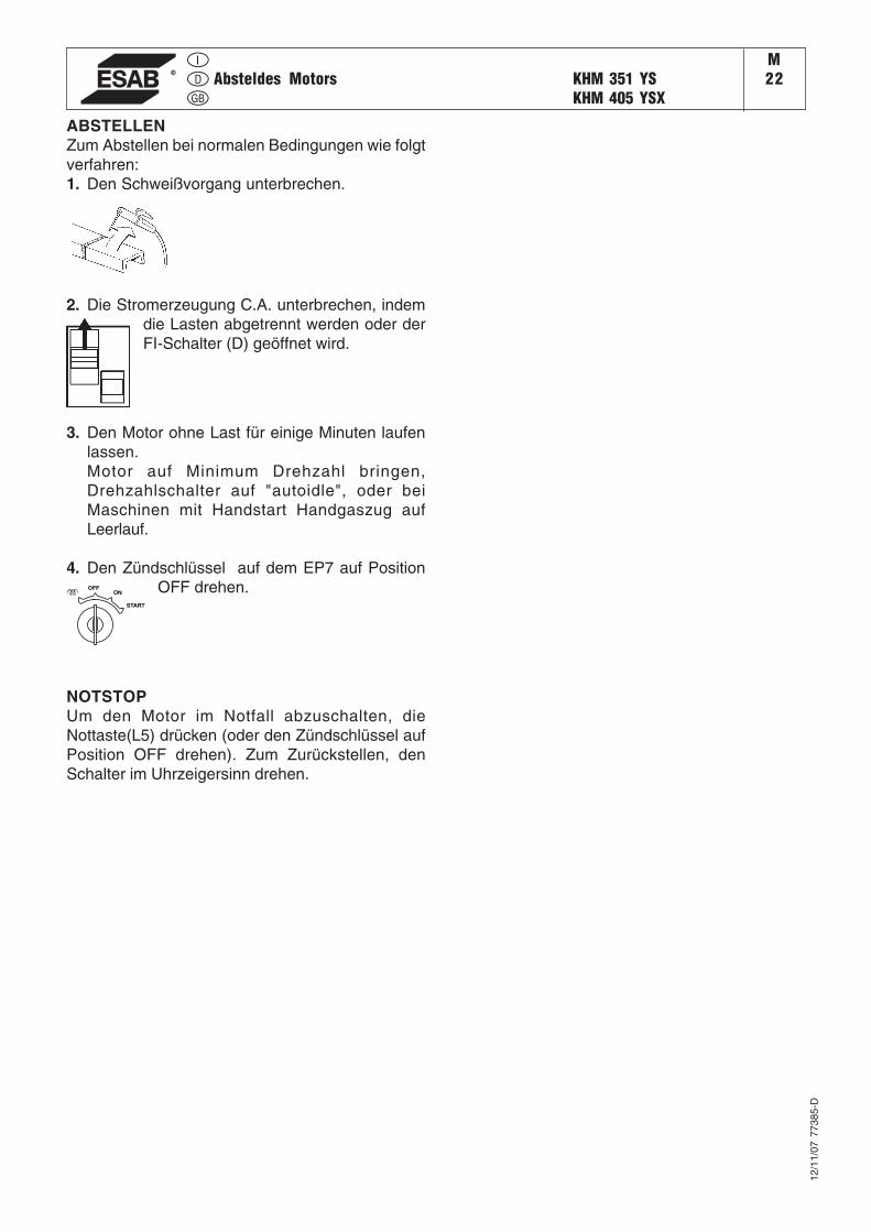
ABSTELLENZum Abstellen bei normalen Bedingungen wie folgtverfahren:1. Den Schweißvorgang unterbrechen.
OFFON
START
2. Die Stromerzeugung C.A. unterbrechen, indemdie Lasten abgetrennt werden oder derFI-Schalter (D) geöffnet wird.
3. Den Motor ohne Last für einige Minuten laufenlassen.Motor auf Minimum Drehzahl bringen,Drehzahlschalter auf "autoidle", oder beiMaschinen mit Handstart Handgaszug aufLeerlauf.
4. Den Zündschlüssel auf dem EP7 auf PositionOFF drehen.
NOTSTOPUm den Motor im Notfall abzuschalten, dieNottaste(L5) drücken (oder den Zündschlüssel aufPosition OFF drehen). Zum Zurückstellen, denSchalter im Uhrzeigersinn drehen.
30/0
1/08
794
12-G
B
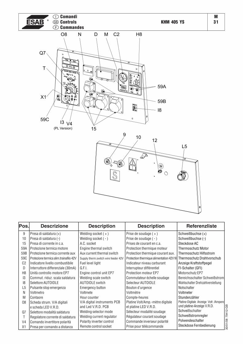
ComandiControlsCommandes
KHM 405 YSM31
Pos. Descrizione Description Description91015
59A59B59CC2D
H8I3I8L5NMO8
Q7T
V4X1
Presa di saldatura (+)Presa di saldatura (-)Presa di corrente in c.a.Protezione termica motoreProtezione termica corrente auxProtezione termica alim.trainafilo 42VIndicatore livello combustibileInterruttore differenziale (30mA)Unità controllo motore EP7Commut. riduz. scala saldaturaSelettore AUTOIDLEPulsante stop emergenzaVoltmetroContaoreScheda strum. V/A digitalie scheda LED V.R.D.Selettore modalità saldaturaRegolatore corrente di saldaturaComando invertitore polaritàPresa per comando a distanza
Welding socket ( + )Welding socket ( - )A.C. socketEngine thermal switchAux current thermal switchSupply therm.switch wire feeder 42V
Fuel level lightG.F.I.Engine control unit EP7Welding scale switchAUTOIDLE switchEmergency buttonVoltmeteHour counterV/A digital instruments PCBand Led V.R.D. PCBWelding selector modeWelding current regulatorPolarity inverter controlRemote control socket
Prise de soudage ( + )Prise de soudage ( - )Prises de courant en c.a.Protection thermique moteurProtection thermique courant aux.Protection thermique alimentation 42V filIndicateur niveau carburantlnterrupteur différentielProtection moteur EP7Commutateur échelle soudageSelecteur AUTOIDLEBouton d’urgenceVoltmètreCompte-heuresPlatine Volt/Amp.-mètre digitaleet platine LED V.R.D.Sélecteur modalité soudageRégulateur courant soudageCommande inverseur polaritéPrise pour télécommande
ReferenzlisteSchweißbuchse (+)Schweißbuchse (-)Steckdose ACThermoschutz MotorThermoschutz HilfsstromThermoschutz DrahtvorschubAnzeige KraftstoffpegelFI-Schalter (GFI)Motorschutz EP7Bereichsschalter SchweißstromWahlschalter DrehzahlverstellungNotschalterVoltmeterStundenzählerPlatine-Digitale Anzeige Volt /Ampereund platine-Anzeige V.R.D.SchveißschalterSchweißstromreglerPolwendeschalterSteckdose Fernbedienung
15
910
12
L5
I8
59A
59B
H8C2DN
Q7
T
X1
I3
M
59CV4
(PL Version)
O8
KHM 405 YSM32
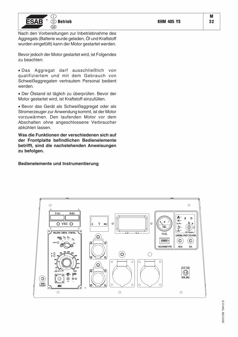
Nach den Vorbereitungen zur Inbetriebnahme desAggregats (Batterie wurde geladen, Öl und Kraftstoffwurden eingefüllt) kann der Motor gestartet werden.
Bevor jedoch der Motor gestartet wird, ist Folgendeszu beachten:
• Das Aggregat darf ausschließlich vonqualifiziertem und mit dem Gebrauch vonSchweißaggregaten vertrautem Personal bedientwerden.
• Der Ölstand ist täglich zu überprüfen. Bevor derMotor gestartet wird, ist Kraftstoff einzufüllen.
• Bevor das Gerät als Schweißaggregat oder alsStromerzeuger zur Anwendung kommt, ist der Motorvorzuwärmen. Den laufenden Motor vor demAbschalten ohne angeschlossene Verbraucherabkühlen lassen.
Was die Funktionen der verschiedenen sich aufder Frontplatte befindlichen Bedienelementebetrifft, sind die nachstehenden Anweisungenzu befolgen.
Bedienelemente und Instrumentierung
30/0
1/08
794
12-D
Betrieb
KHM 405 YSM
32.1
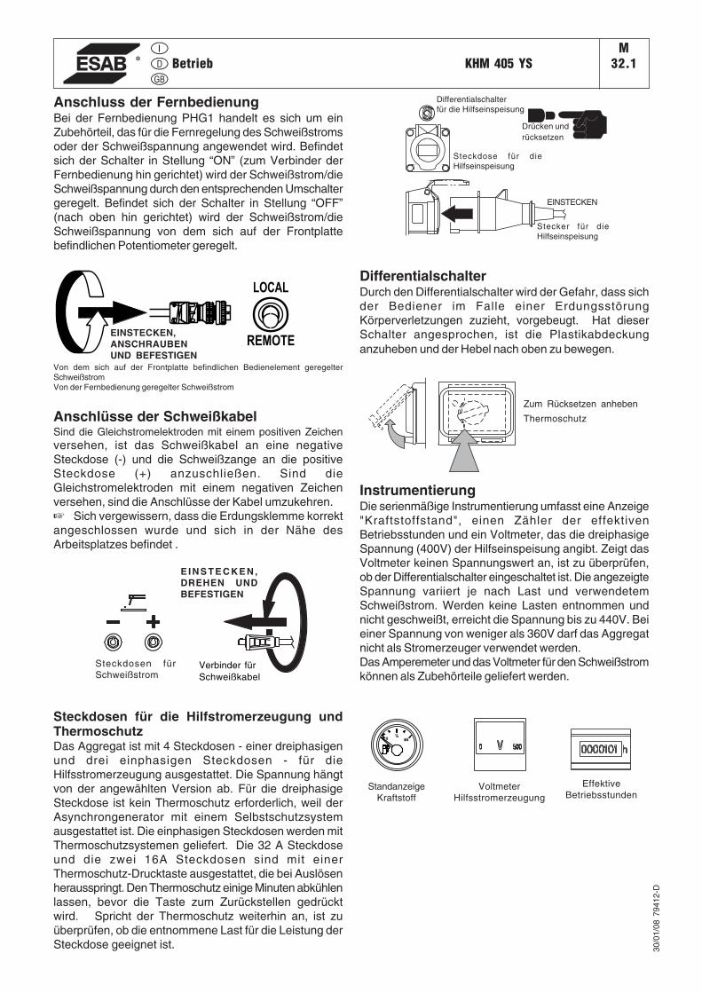
Anschlüsse der SchweißkabelSind die Gleichstromelektroden mit einem positiven Zeichenversehen, ist das Schweißkabel an eine negativeSteckdose (-) und die Schweißzange an die positiveSteckdose (+) anzuschließen. Sind dieGleichstromelektroden mit einem negativen Zeichenversehen, sind die Anschlüsse der Kabel umzukehren.☞ Sich vergewissern, dass die Erdungsklemme korrektangeschlossen wurde und sich in der Nähe desArbeitsplatzes befindet .
Steckdosen für die Hilfstromerzeugung undThermoschutzDas Aggregat ist mit 4 Steckdosen - einer dreiphasigenund drei einphasigen Steckdosen - für dieHilfsstromerzeugung ausgestattet. Die Spannung hängtvon der angewählten Version ab. Für die dreiphasigeSteckdose ist kein Thermoschutz erforderlich, weil derAsynchrongenerator mit einem Selbstschutzsystemausgestattet ist. Die einphasigen Steckdosen werden mitThermoschutzsystemen geliefert. Die 32 A Steckdoseund die zwei 16A Steckdosen sind mit einerThermoschutz-Drucktaste ausgestattet, die bei Auslösenherausspringt. Den Thermoschutz einige Minuten abkühlenlassen, bevor die Taste zum Zurückstellen gedrücktwird. Spricht der Thermoschutz weiterhin an, ist zuüberprüfen, ob die entnommene Last für die Leistung derSteckdose geeignet ist.
Zum Rücksetzen anheben
Thermoschutz
30/0
1/08
794
12-D
DifferentialschalterDurch den Differentialschalter wird der Gefahr, dass sichder Bediener im Falle einer ErdungsstörungKörperverletzungen zuzieht, vorgebeugt. Hat dieserSchalter angesprochen, ist die Plastikabdeckunganzuheben und der Hebel nach oben zu bewegen.
Anschluss der FernbedienungBei der Fernbedienung PHG1 handelt es sich um einZubehörteil, das für die Fernregelung des Schweißstromsoder der Schweißspannung angewendet wird. Befindetsich der Schalter in Stellung “ON” (zum Verbinder derFernbedienung hin gerichtet) wird der Schweißstrom/dieSchweißspannung durch den entsprechenden Umschaltergeregelt. Befindet sich der Schalter in Stellung “OFF”(nach oben hin gerichtet) wird der Schweißstrom/dieSchweißspannung von dem sich auf der Frontplattebefindlichen Potentiometer geregelt.
InstrumentierungDie serienmäßige Instrumentierung umfasst eine Anzeige"Kraftstoffstand", einen Zähler der effektivenBetriebsstunden und ein Voltmeter, das die dreiphasigeSpannung (400V) der Hilfseinspeisung angibt. Zeigt dasVoltmeter keinen Spannungswert an, ist zu überprüfen,ob der Differentialschalter eingeschaltet ist. Die angezeigteSpannung variiert je nach Last und verwendetemSchweißstrom. Werden keine Lasten entnommen undnicht geschweißt, erreicht die Spannung bis zu 440V. Beieiner Spannung von weniger als 360V darf das Aggregatnicht als Stromerzeuger verwendet werden.Das Amperemeter und das Voltmeter für den Schweißstromkönnen als Zubehörteile geliefert werden.
Betrieb
EINSTECKEN,ANSCHRAUBENUND BEFESTIGEN
Von dem sich auf der Frontplatte befindlichen Bedienelement geregelterSchweißstromVon der Fernbedienung geregelter Schweißstrom
LOCAL
REMOTE
E I N S T E C K E N ,DREHEN UNDBEFESTIGEN
Verbinder fürSchweißkabel
Steckdosen fürSchweißstrom
TO
PRESS RESET
CIRCUIT BREAKER
TO
PRESS RESET
CIRCUIT BREAKER
Drücken undrücksetzen
Differentialschalterfür die Hilfseinspeisung
Steckdose für dieHilfseinspeisung
EINSTECKEN
Stecker für dieHilfseinspeisung
4/4
½0
StandanzeigeKraftstoff
EffektiveBetriebsstunden
VoltmeterHilfsstromerzeugung
MOTORSCHUTZMOTORSCHUTZEP7
M32.2
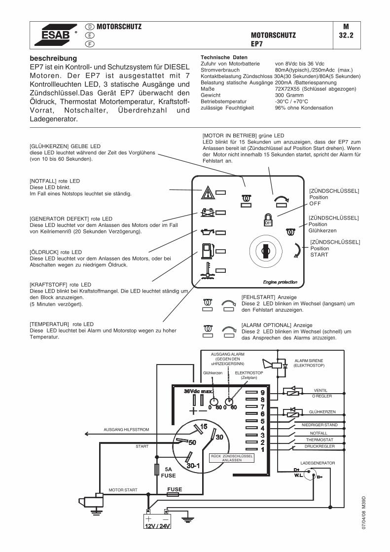
beschreibungEP7 ist ein Kontroll- und Schutzsystem für DIESELMotoren. Der EP7 ist ausgestattet mit 7Kontrollleuchten LED, 3 statische Ausgänge undZündschlüssel.Das Gerät EP7 überwacht denÖldruck, Thermostat Motortemperatur, Kraftstoff-Vorrat, Notschalter, Überdrehzahl undLadegenerator.
Technische DatenZufuhr von Motorbatterie von 8Vdc bis 36 VdcStromverbrauch 80mA(typisch),/250mAdc (max.)Kontaktbelastung Zündschloss 30A(30 Sekunden)/80A(5 Sekunden)Belastung statische Ausgänge 200mA /BatteriespannungMaße 72X72X55 (Schlüssel abgezogen)Gewicht 300 GrammBetriebstemperatur -30°C / +70°Czulässige Feuchtigkeit 96% ohne Kondensation
[GLÜHKERZEN] GELBE LEDdiese LED leuchtet während der Zeit des Vorglühens(von 10 bis 60 Sekunden).
[GENERATOR DEFEKT] rote LEDDiese LED leuchtet vor dem Anlassen des Motors oder im Fallvon Keilriemenriß (20 Sekunden Verzögerung).
[ÖLDRUCK] rote LEDDiese LED leuchtet vor dem Anlassen des Motors, oder beiAbschalten wegen zu niedrigem Öldruck.
[KRAFTSTOFF] rote LEDDiese LED blinkt bei Kraftstoffmangel. Die LED leuchtet ständig umden Block anzuzeigen.(5 Minuten verzögert).
[TEMPERATUR] rote LEDDiese LED leuchtet bei Alarm und Motorstop wegen zu hoherTemperatur.
[MOTOR IN BETRIEB] grüne LEDLED blinkt für 15 Sekunden um anzuzeigen, dass der EP7 zumAnlassen bereit ist (Zündschlüssel auf Position Start drehen). Wennder Motor nicht innerhalb 15 Sekunden startet, spricht der Alarm fürFehlstart an.
[ZÜNDSCHLÜSSEL]PositionOFF
[ZÜNDSCHLÜSSEL]PositionGlühkerzen
[ZÜNDSCHLÜSSEL]PositionSTART
5AFUSE
FUSE
[NOTFALL] rote LEDDiese LED blinkt.Im Fall eines Notstops leuchtet sie ständig.
Glühkerzen
RÜCK ZÜNDSCHLÜSSELANLASSEN
AUSGANG HILFSSTROM
START
MOTOR START
ELEKTROSTOP(Zeitplan)
VENTILO REGLER
ALARM SIRENE(ELEKTROSTOP)
GLÜHKERZEN
NIEDRIGER STAND
NOTFALL
THERMOSTAT
DRUCKREGLER
[FEHLSTART] AnzeigeDiese 2 LED blinken im Wechsel (langsam) umden Fehlstart anzuzeigen.
[ALARM OPTIONAL] AnzeigeDiese 2 LED blinken im Wechsel (schnell) umdas Ansprechen des Alarms anzuzeigen.
AUSGANG ALARM(GEGEN DEN
uHRZEIGERSINN)
LADEGENERATOR
07/0
4/08
M39
D
GEBRAUCH WELDING DIGITAL CONTROLM
33.1
12/0
5/05
M33
_WD
C_D
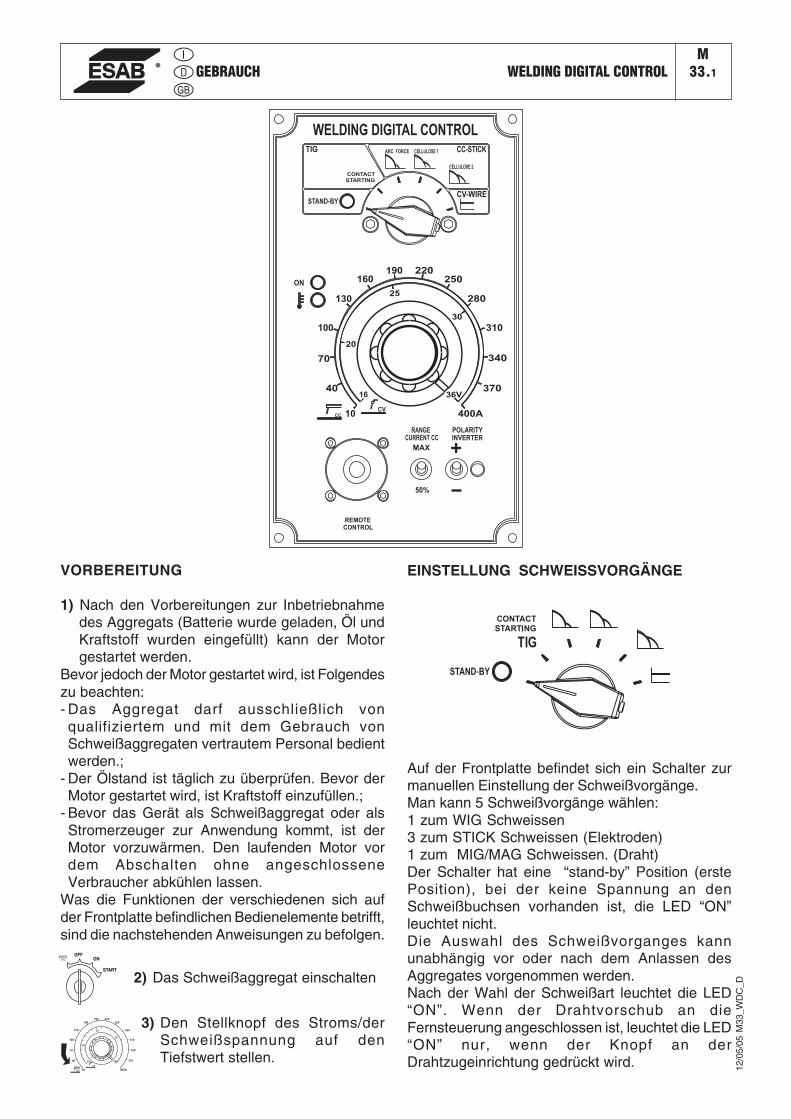
VORBEREITUNG
1) Nach den Vorbereitungen zur Inbetriebnahmedes Aggregats (Batterie wurde geladen, Öl undKraftstoff wurden eingefüllt) kann der Motorgestartet werden.
Bevor jedoch der Motor gestartet wird, ist Folgendeszu beachten:- Das Aggregat darf ausschließlich vonqualifiziertem und mit dem Gebrauch vonSchweißaggregaten vertrautem Personal bedientwerden.;
- Der Ölstand ist täglich zu überprüfen. Bevor derMotor gestartet wird, ist Kraftstoff einzufüllen.;
- Bevor das Gerät als Schweißaggregat oder alsStromerzeuger zur Anwendung kommt, ist derMotor vorzuwärmen. Den laufenden Motor vordem Abschalten ohne angeschlosseneVerbraucher abkühlen lassen.
Was die Funktionen der verschiedenen sich aufder Frontplatte befindlichen Bedienelemente betrifft,sind die nachstehenden Anweisungen zu befolgen.
2) Das Schweißaggregat einschalten
OFFON
START
3) Den Stellknopf des Stroms/derSchweißspannung auf denTiefstwert stellen.
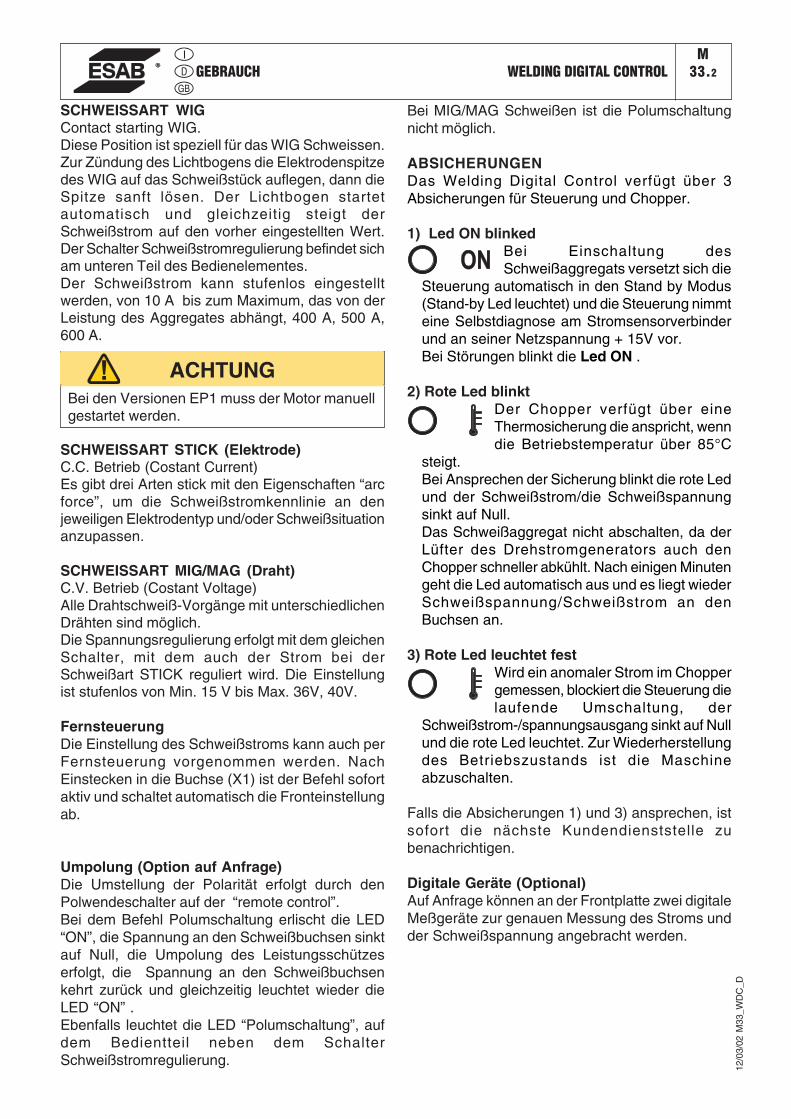
EINSTELLUNG SCHWEISSVORGÄNGE
CVCC
STAND-BY
CONTACT
STARTING
REMOTE
CONTROL
70
20
25
40
100
WELDING DIGITAL CONTROL
130
160190 220
250
280
310
340
370
400A
36V16
10
30
ON
POLARITY
CURRENT CC
MAX
50%
INVERTER
RANGE
TIG ARC FORCE CELLULOSE 1
CELLULOSE 2
CC-STICK
CV-WIRE
Auf der Frontplatte befindet sich ein Schalter zurmanuellen Einstellung der Schweißvorgänge.Man kann 5 Schweißvorgänge wählen:1 zum WIG Schweissen3 zum STICK Schweissen (Elektroden)1 zum MIG/MAG Schweissen. (Draht)Der Schalter hat eine “stand-by” Position (erstePosition), bei der keine Spannung an denSchweißbuchsen vorhanden ist, die LED “ON”leuchtet nicht.Die Auswahl des Schweißvorganges kannunabhängig vor oder nach dem Anlassen desAggregates vorgenommen werden.Nach der Wahl der Schweißart leuchtet die LED“ON”. Wenn der Drahtvorschub an dieFernsteuerung angeschlossen ist, leuchtet die LED“ON” nur, wenn der Knopf an derDrahtzugeinrichtung gedrückt wird.
GEBRAUCH WELDING DIGITAL CONTROLM
33.2
12/0
3/02
M33
_WD
C_D
SCHWEISSART WIGContact starting WIG.Diese Position ist speziell für das WIG Schweissen.Zur Zündung des Lichtbogens die Elektrodenspitzedes WIG auf das Schweißstück auflegen, dann dieSpitze sanft lösen. Der Lichtbogen startetautomatisch und gleichzeitig steigt derSchweißstrom auf den vorher eingestellten Wert.Der Schalter Schweißstromregulierung befindet sicham unteren Teil des Bedienelementes.Der Schweißstrom kann stufenlos eingestelltwerden, von 10 A bis zum Maximum, das von derLeistung des Aggregates abhängt, 400 A, 500 A,600 A.
Bei MIG/MAG Schweißen ist die Polumschaltungnicht möglich.
ABSICHERUNGENDas Welding Digital Control verfügt über 3Absicherungen für Steuerung und Chopper.
1) Led ON blinkedBei Einschaltung desSchweißaggregats versetzt sich die
Steuerung automatisch in den Stand by Modus(Stand-by Led leuchtet) und die Steuerung nimmteine Selbstdiagnose am Stromsensorverbinderund an seiner Netzspannung + 15V vor.Bei Störungen blinkt die Led ON .
2) Rote Led blinktDer Chopper verfügt über eineThermosicherung die anspricht, wenndie Betriebstemperatur über 85°C
steigt.Bei Ansprechen der Sicherung blinkt die rote Ledund der Schweißstrom/die Schweißspannungsinkt auf Null.Das Schweißaggregat nicht abschalten, da derLüfter des Drehstromgenerators auch denChopper schneller abkühlt. Nach einigen Minutengeht die Led automatisch aus und es liegt wiederSchweißspannung/Schweißstrom an denBuchsen an.
3) Rote Led leuchtet festWird ein anomaler Strom im Choppergemessen, blockiert die Steuerung dielaufende Umschaltung, der
Schweißstrom-/spannungsausgang sinkt auf Nullund die rote Led leuchtet. Zur Wiederherstellungdes Betriebszustands ist die Maschineabzuschalten.
Falls die Absicherungen 1) und 3) ansprechen, istsofort die nächste Kundendienststelle zubenachrichtigen.
Digitale Geräte (Optional)Auf Anfrage können an der Frontplatte zwei digitaleMeßgeräte zur genauen Messung des Stroms undder Schweißspannung angebracht werden.
SCHWEISSART STICK (Elektrode)C.C. Betrieb (Costant Current)Es gibt drei Arten stick mit den Eigenschaften “arcforce”, um die Schweißstromkennlinie an denjeweiligen Elektrodentyp und/oder Schweißsituationanzupassen.
SCHWEISSART MIG/MAG (Draht)C.V. Betrieb (Costant Voltage)Alle Drahtschweiß-Vorgänge mit unterschiedlichenDrähten sind möglich.Die Spannungsregulierung erfolgt mit dem gleichenSchalter, mit dem auch der Strom bei derSchweißart STICK reguliert wird. Die Einstellungist stufenlos von Min. 15 V bis Max. 36V, 40V.
FernsteuerungDie Einstellung des Schweißstroms kann auch perFernsteuerung vorgenommen werden. NachEinstecken in die Buchse (X1) ist der Befehl sofortaktiv und schaltet automatisch die Fronteinstellungab.
Umpolung (Option auf Anfrage)Die Umstellung der Polarität erfolgt durch denPolwendeschalter auf der “remote control”.Bei dem Befehl Polumschaltung erlischt die LED“ON”, die Spannung an den Schweißbuchsen sinktauf Null, die Umpolung des Leistungsschützeserfolgt, die Spannung an den Schweißbuchsenkehrt zurück und gleichzeitig leuchtet wieder dieLED “ON” .Ebenfalls leuchtet die LED “Polumschaltung”, aufdem Bedientteil neben dem SchalterSchweißstromregulierung.
Bei den Versionen EP1 muss der Motor manuellgestartet werden.
ACHTUNG
GEBRAUCH WELDING DIGITAL CONTROLM
33.4
12/0
3/02
M33
_WD
C_D
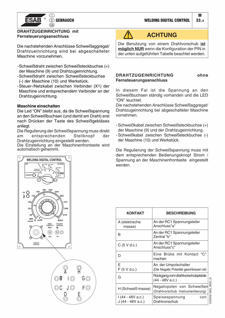
DRAHTZUGEINRICHTUNG mitFernsteuerungsanschluss
Die nachstehenden Anschlüsse Schweißaggregat/Drahtzueinrichtung sind bei abgeschalteterMaschine vorzunehmen.
-Schweißdraht zwischen Schweißsteckbuchse (+)der Maschine (9) und Drahtzugeinrichtung.
-Schweißdraht zwischen Schweißsteckbuchse(-) der Maschine (10) und Werkstück.
-Steuer-/Netzkabel zwischen Verbinder (X1) derMaschine und entsprechendem Verbinder an derDrahtzugeinrichtung.
Maschine einschaltenDie Led “ON” bleibt aus, da die Schweißspannungan den Schweißbuchsen (und damit am Draht) erstnach Drücken der Taste des Schweißgebläsesanliegt.Die Regulierung der Schweißspannung muss direktam entsprechenden Stellknopf derDrahtzugeinrichtung eingestellt werden.Die Einstellung an der Maschinenfrontseite wirdautomatisch gehemmt.
Die Benutzung von einem Drahtvorschub istmöglich NUR wenn die Konfiguration der PIN inder unten aufgeführten Tabelle beachtet werden.
ACHTUNG
CVCC
STAND-BY
CONTACT
STARTING
REMOTE
CONTROL
70
20
25
40
100
WELDING DIGITAL CONTROL
130
160190 220
250
280
310
340
370
400A
36V16
10
30
ON
POLARITY
CURRENT CC
MAX
50%
INVERTER
RANGE
TIG ARC FORCE CELLULOSE 1
CELLULOSE 2
CC-STICK
CV-WIRE
KONTAKT
A (elektrische masse)
B
C (5 V d.c.)
D
EF (5 V d.c.)
G
H (Schweiß masse)
I (44 - 48V a.c.)J (44 - 48V a.c.)
BESCHREIBUNG
An der RC1 SpannungsteilerAnschluss"a"
An der RC1 SpannungsteilerZentral "b"
An der RC1 SpannungsteilerAnschluss"c"
Eine Brüke mit Kontact "C"machen
An der Umpolschalter(Die Negativ Polarität geschlossen ist)
Rückgang vom drahtvorschubpistole(44 - 48V a.c.)
Negativpolen von Schweißen(Drahtvorschub Instrumentierung)
Speisespannung vonDrahtvonschub
DRAHTZUGEINRICHTUNG ohneFernsteuerungsanschluss
In diesem Fal ist die Spannung an denSchweißbuchsen ständig vorhanden und die LED“ON” leuchtet.Die nachstehenden Anschlüsse Schweißaggregat/Drahtzugeinrichtung bei abgeschalteter Maschinevornehmen.
- Schweißkabel zwischen Schweißsteckbuchse (+)der Maschine (9) und der Drahtzugeinrichtung.
- Schweißkabel zwischen Schweißsteckbuchse (-)der Maschine (10) und Werkstück.
Die Regulierung der Schweißspannung muss mitdem entsprechenden Bedienungsknopf Strom /Spannung an der Maschinenfrontseite eingestelltwerden.
REMOTE CONTROL PHG1B-PHG1B/PL KHMM
38.8
16/0
1/08
M38
GB
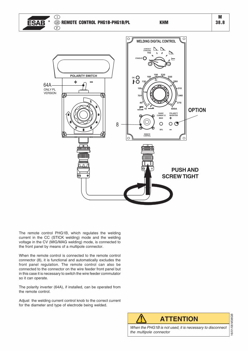
PUSH ANDSCREW TIGHT
ONLY PLVERSION
When the PHG1B is not used, it is necessary to disconnectthe multipole connector
ATTENTION
The remote control PHG1B, which regulates the weldingcurrent in the CC (STICK welding) mode and the weldingvoltage in the CV (MIG/MAG welding) mode, is connected tothe front panel by means of a multipole connector.
When the remote control is connected to the remote controlconnector (8), it is functional and automatically excludes thefront panel regulation. The remote control can also beconnected to the connector on the wire feeder front panel butin this case it is necessary to switch the wire feeder commutatorso it can operate.
The polarity inverter (64A), if installed, can be operated fromthe remote control.
Adjust the welding current control knob to the correct currentfor the diameter and type of electrode being welded.
�������
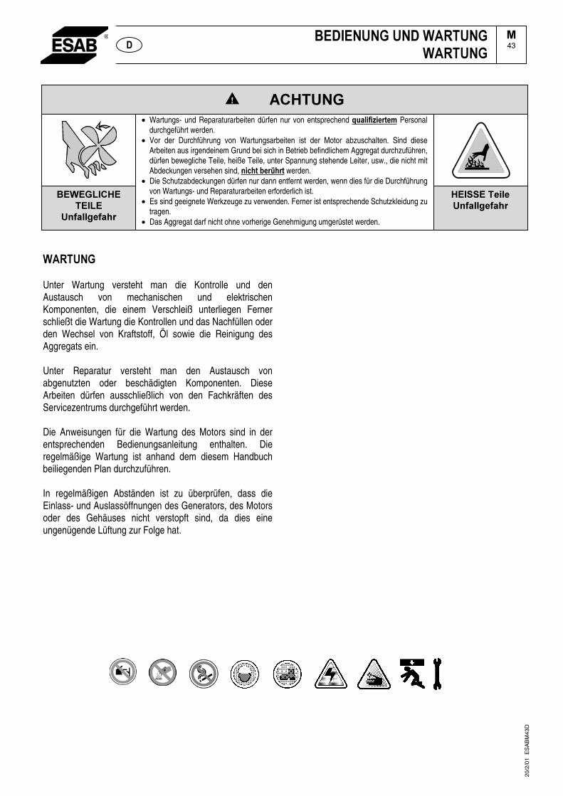
Unter Wartung versteht man die Kontrolle und den Austausch von mechanischen und elektrischen Komponenten, die einem Verschleiß unterliegen Ferner schließt die Wartung die Kontrollen und das Nachfüllen oder den Wechsel von Kraftstoff, Öl sowie die Reinigung des Aggregats ein.
Unter Reparatur versteht man den Austausch von abgenutzten oder beschädigten Komponenten. Diese Arbeiten dürfen ausschließlich von den Fachkräften des Servicezentrums durchgeführt werden.
Die Anweisungen für die Wartung des Motors sind in der entsprechenden Bedienungsanleitung enthalten. Die regelmäßige Wartung ist anhand dem diesem Handbuch beiliegenden Plan durchzuführen.
In regelmäßigen Abständen ist zu überprüfen, dass die Einlass- und Auslassöffnungen des Generators, des Motors oder des Gehäuses nicht verstopft sind, da dies eine ungenügende Lüftung zur Folge hat.
��
20/2
/01
ES
AB
M43
D
�� �����������������������
�43
����������������• Wartungs- und Reparaturarbeiten dürfen nur von entsprechend ��������������Personal
durchgeführt werden.• Vor der Durchführung von Wartungsarbeiten ist der Motor abzuschalten. Sind diese
Arbeiten aus irgendeinem Grund bei sich in Betrieb befindlichem Aggregat durchzuführen,dürfen bewegliche Teile, heiße Teile, unter Spannung stehende Leiter, usw., die nicht mit Abdeckungen versehen sind, ������������ werden.
• Die Schutzabdeckungen dürfen nur dann entfernt werden, wenn dies für die Durchführungvon Wartungs- und Reparaturarbeiten erforderlich ist.
• Es sind geeignete Werkzeuge zu verwenden. Ferner ist entsprechende Schutzkleidung zu tragen.
• Das Aggregat darf nicht ohne vorherige Genehmigung umgerüstet werden.
�������������������������
���������������
�������������
�
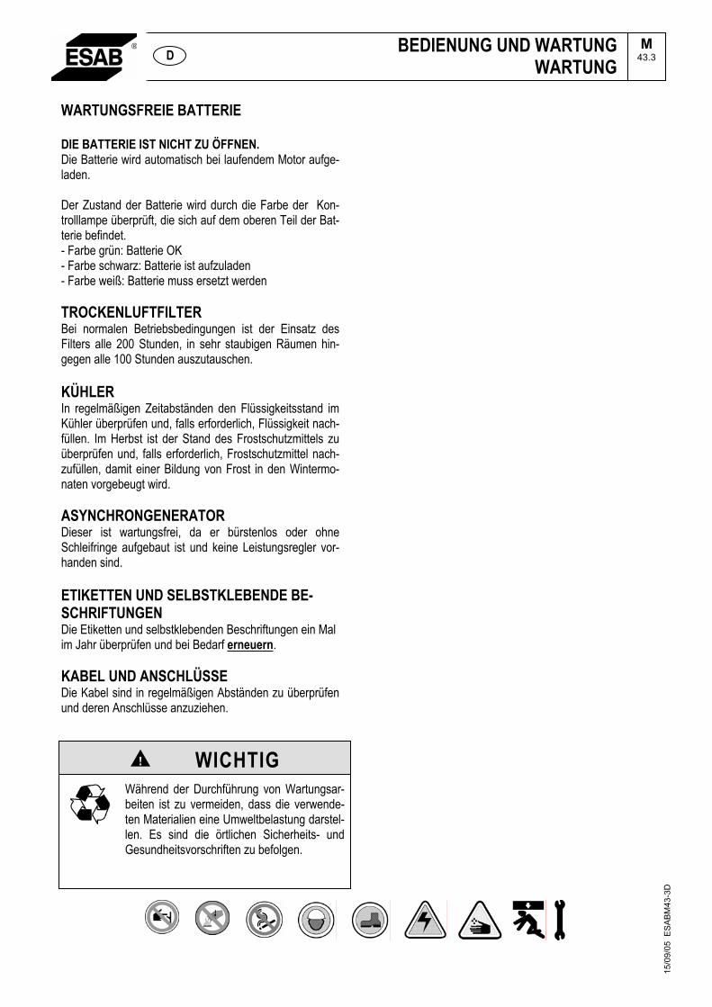
WICHTIGWährend der Durchführung von Wartungsar-beiten ist zu vermeiden, dass die verwende-ten Materialien eine Umweltbelastung darstel-len. Es sind die örtlichen Sicherheits- und Gesundheitsvorschriften zu befolgen.
15/0
9/05
ES
AB
M43
-3D
WARTUNGSFREIE BATTERIE
DIE BATTERIE IST NICHT ZU ÖFFNEN.Die Batterie wird automatisch bei laufendem Motor aufge-laden.
Der Zustand der Batterie wird durch die Farbe der Kon-trolllampe überprüft, die sich auf dem oberen Teil der Bat-terie befindet. - Farbe grün: Batterie OK - Farbe schwarz: Batterie ist aufzuladen - Farbe weiß: Batterie muss ersetzt werden
TROCKENLUFTFILTERBei normalen Betriebsbedingungen ist der Einsatz des Filters alle 200 Stunden, in sehr staubigen Räumen hin-gegen alle 100 Stunden auszutauschen.
KÜHLERIn regelmäßigen Zeitabständen den Flüssigkeitsstand im Kühler überprüfen und, falls erforderlich, Flüssigkeit nach-füllen. Im Herbst ist der Stand des Frostschutzmittels zu überprüfen und, falls erforderlich, Frostschutzmittel nach-zufüllen, damit einer Bildung von Frost in den Wintermo-naten vorgebeugt wird.
ASYNCHRONGENERATORDieser ist wartungsfrei, da er bürstenlos oder ohne Schleifringe aufgebaut ist und keine Leistungsregler vor-handen sind.
ETIKETTEN UND SELBSTKLEBENDE BE-SCHRIFTUNGENDie Etiketten und selbstklebenden Beschriftungen ein Mal im Jahr überprüfen und bei Bedarf erneuern.
KABEL UND ANSCHLÜSSEDie Kabel sind in regelmäßigen Abständen zu überprüfen und deren Anschlüsse anzuziehen.
BEDIENUNG UND WARTUNGWARTUNG
M43.3 D
Wird das Aggregat länger als 30 Tage nicht benutzt, hat man sich zu vergewissern, dass dieses in einem witterungsgeschützten Raum gelagert wird, damit Schäden auf Grund von Rost, Korrosion, usw. vermieden werden.
������ !�!���
Wird das Aggregat nur über einen kurzen Zeitraum gelagert, empfiehlt es sich, den Motor alle 10 Tage anzulassen und ca. 15 – 30 Minuten mit Lastaufnahme laufen zu lassen, damit das Öl einwandfrei verteilt, die Batterie geladen und eine Blockierung des Einspritzsystems vermieden wird.
Im Falle längerer Lagerzeiten sind die in der Bedienungsanleitung des Motors enthaltenen Vorschriften zu befolgen.
Das Aggregat sorgfältig reinigen.
Das Aggregat mit einer Plastikhülle abdecken und an einem trockenen Ort lagern.
���"#��� ������ ��� �����$*������ ��� ����� �������� ��� ��� ���������� � �����!������� + ���� ����� ����� ,�!������ ���� ���������-�������(�������������������.����%��������������$���������$�������
20/2
/01
ES
AB
M45
D
���������������������������
�45�

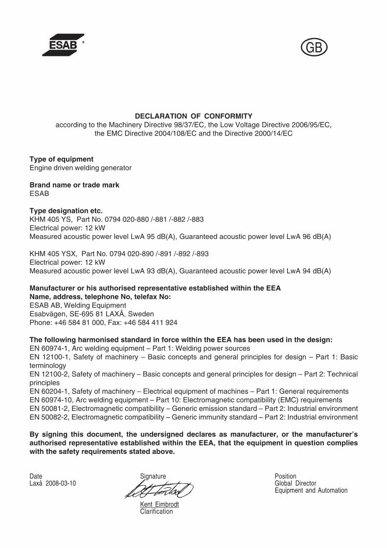
DECLARATION OF CONFORMITYaccording to the Machinery Directive 98/37/EC, the Low Voltage Directive 2006/95/EC,
the EMC Directive 2004/108/EC and the Directive 2000/14/EC
Type of equipmentEngine driven welding generator
Brand name or trade markESAB
Type designation etc.KHM 405 YS, Part No. 0794 020-880 /-881 /-882 /-883Electrical power: 12 kWMeasured acoustic power level LwA 95 dB(A), Guaranteed acoustic power level LwA 96 dB(A)
KHM 405 YSX, Part No. 0794 020-890 /-891 /-892 /-893Electrical power: 12 kWMeasured acoustic power level LwA 93 dB(A), Guaranteed acoustic power level LwA 94 dB(A)
Manufacturer or his authorised representative established within the EEAName, address, telephone No, telefax No:ESAB AB, Welding EquipmentEsabvägen, SE-695 81 LAXÅ, SwedenPhone: +46 584 81 000, Fax: +46 584 411 924
The following harmonised standard in force within the EEA has been used in the design:EN 60974-1, Arc welding equipment – Part 1: Welding power sourcesEN 12100-1, Safety of machinery – Basic concepts and general principles for design – Part 1: BasicterminologyEN 12100-2, Safety of machinery – Basic concepts and general principles for design – Part 2: TechnicalprinciplesEN 60204-1, Safety of machinery – Electrical equipment of machines – Part 1: General requirementsEN 60974-10, Arc welding equipment – Part 10: Electromagnetic compatibility (EMC) requirementsEN 50081-2, Electromagnetic compatibility – Generic emission standard – Part 2: Industrial environmentEN 50082-2, Electromagnetic compatibility – Generic immunity standard – Part 2: Industrial environment
By signing this document, the undersigned declares as manufacturer, or the manufacturer’sauthorised representative established within the EEA, that the equipment in question complieswith the safety requirements stated above.
Date Signature PositionLaxå 2008-03-10 Global Director
Equipment and Automation
Kent EimbrodtClarification
KHM 405 YSM1Index
Dear Customer,
We wish to thank you for having bought this product.
Please take time to read this manual and familiarize yourself with the machine before attempting to use it.
If you should have questions or problems please contact the nearest authorized Service Center. Theyhave the experience and original spare parts. The use of non-original spare parts will void the warranty.
TABLE OF CONTENTS
DESCRIPTION PAGE
GENERAL INFORMATIONINFORMATION ABOUT THIS MANUAL M 2DESCRIPTION - SYMBOLS M 2.1PRECAUTIONS - GENERAL M 2.5PRECAUTIONS - ENGINE DRIVEN WELDERS M 2.5.1TRANSPORT M 4ASSEMBLY OF SITE TOW FOR KHM 405 M 6.2INSTALLATION INFORMATION M 2.6, 2.7
OPERATIONUNPACKING M 3TECHNICAL DATA AND MACHINE DESCRIPTION M 1.5, M 1.6PREPARING THE UNIT M 20STARTING THE ENGINE THE USE M 21STOPPING THE DIESEL ENGINE M 22CONTROLS M 31OPERATING M 32...USE - WELDING DIGITAL CONTROL M 33...REMOTE CONTROL PHG 1 M 38.8MAINTENANCE M 43, M 43.3STORAGE M 45DIMENSIONS M 53
SCHEMATICS AND SPARE PARTSWIRING DIAGRAM – ENGINE M 61.1WIRING DIAGRAM – AUXILIARY 400T/ 230Mx2 DT M 61.2WIRING DIAGRAM – WELDING POWER M 61.3WIRING DIAGRAM – WELDING CONTROL M 61.4
30/0
1/08
794
12-G
B
INFO KHMM2
07/0
1/08
M2G
B
GENERAL INFORMATION
− In the envelope where you found this manual you will alsofind an Owner’s manual for the engine, and accessories (ifrequired).
This product has been designed for welding and generationof electrical power for tools and other electrical devices usedin construction; ANY OTHER USE, is not permitted and wecannot be held responsible for injuries or damages resultingfrom such incorrect use.
Our products are made in conformity with the safety norms inforce in order to avoid injury to persons or damage to themachine or other things.
☞ Warranty is not valid if not carried out by ESABauthorized service agent.
Making modifications to the machine without our writtenauthorization will void the warranty and release us from anyliability.
ABOUT THIS MANUAL
Before using the machine please read this manual attentivelyand follow the instructions contained in it. This will help avoidproblems, possible injury and damage to the machine.
The manual is written for experienced, qualified personnel,who are familiar with health and safety laws and relatedregulations.
This manual is an integral part of the product and should bekept in a safe place so that it will be available for consultationduring the life of the product. If the machine is sold the manualshould be transferred to the new owner.
Some figures contained in this manual are designed to helpidentify certain parts and may not correspond to the machinein your possession.
☞ Notice: the manufacturer may make improvements ormodifications to the product or its accessories as describedin this manual without updating the manual.
ATTENTION
NOTE
IMPORTANT
CAUTION
WARNING
DANGEROUS
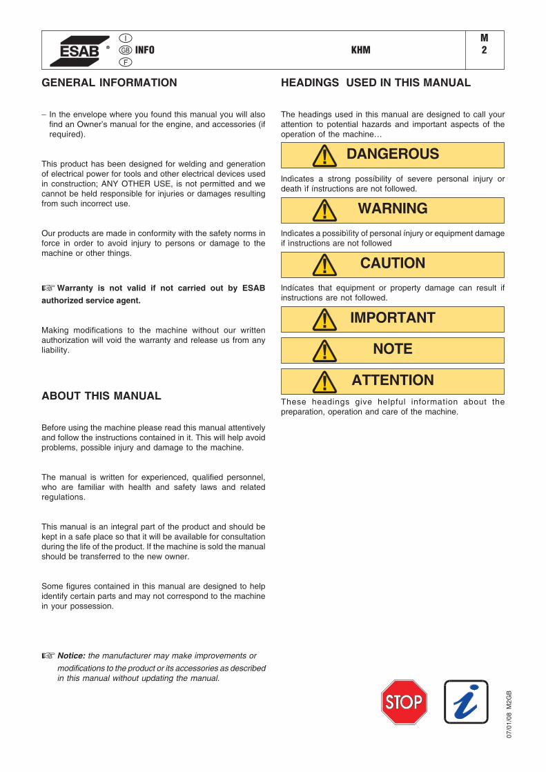
HEADINGS USED IN THIS MANUAL
The headings used in this manual are designed to call yourattention to potential hazards and important aspects of theoperation of the machine…
lndìcates a strong possíbility of severe personal injury ordeath ìf ínstructions are not followed.
lndìcates a possibìlìty of personal ínjury or equipment damageif ìnstructions are not followed
lndícates that equipment or property damage can result ifinstructions are not followed.
These headings give helpful information about thepreparation, operation and care of the machine.

SYMBOLS KHMM
2.1
GENERAL SYMBOLS
STOP – Read with great attention
Read with attention
WRENCH - Use the correct tools for the type ofwork being done
WARNING SYMBOLS
ATTENTION - If this advice is not followed peopleor things can be hurt or damaged.
HIGH VOLTAGE - Do not touch – risk of injury ordeath.
FIRE - Risk of fire.
HEAT - Hot surfaces.
EXPLOSIVE - Explosive material or danger ofexplosion, in general.
NO WATER - Do not use water as it can causeshortcircuits or other damage.
NO SMOKING - Cigarettes, matches or lighterscan start a fire or explosion.
ACIDS - Danger of corrosion or burns.
SAFETY SYMBOLS
Use the correct protective devices for the type of weldingbeing done
Use protective clothing, etc. specificallydesigned for the type of welding being done.
Protect yourself when doing maintenance on the machine-
It is advisable to protect yourself when carryingout maintenance, such as filling the battery,refuelling, etc.
Pay attention to safety precautions when moving themachine
Refer to the instructions before moving themachine
Wear indicated safety clothing -
It is compulsory to wear the personalprotection items shown when using theequipment.
Use required safety devices -
Safety devices suitable for the type of weldingand the location of the job must be used.
Do not use water on electrical fires -
It is prohibited to use water to put our fires inelectrical equipment.
Do not touch without having disconnected the electricity -
It is prohibited to work on the machine until theelectricity has been turned off.
Welding prohibited -
It is forbidden to weld in areas containingexplosive gases.
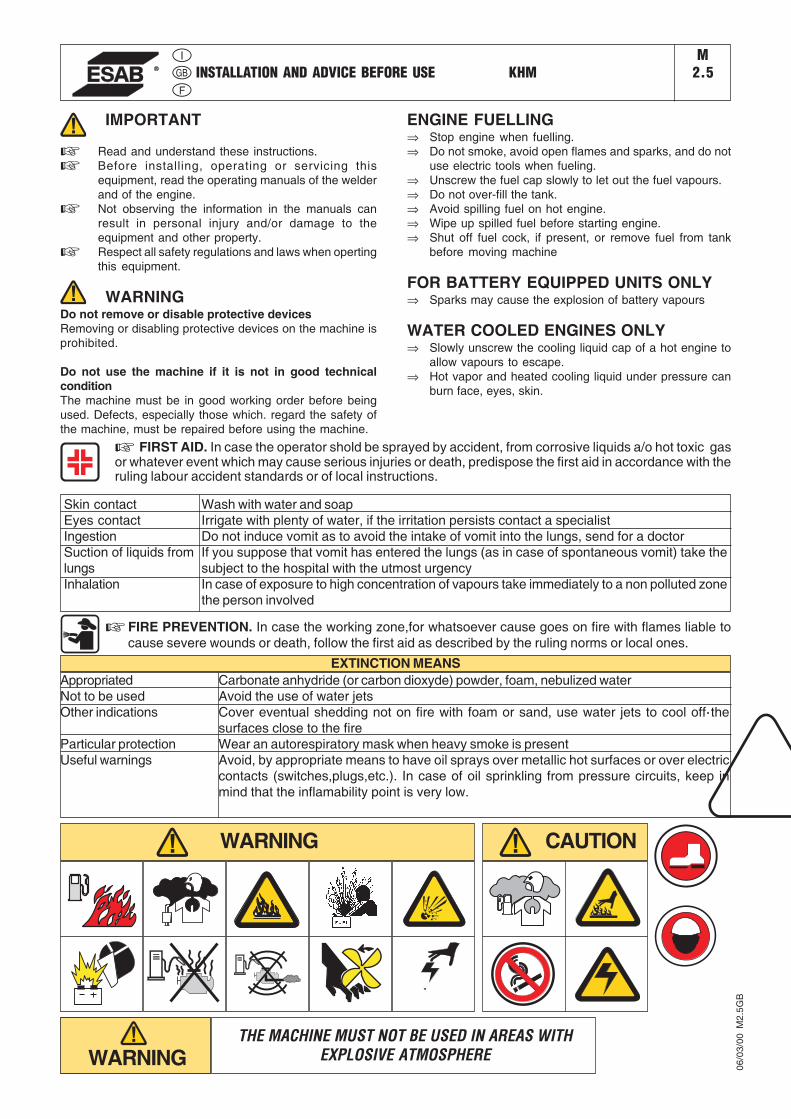
IMPORTANT
☞ Read and understand these instructions.
☞ Before installing, operating or servicing thisequipment, read the operating manuals of the welderand of the engine.
☞ Not observing the information in the manuals canresult in personal injury and/or damage to theequipment and other property.
☞ Respect all safety regulations and laws when opertingthis equipment.
WARNINGDo not remove or disable protective devicesRemoving or disabling protective devices on the machine isprohibited.
Do not use the machine if it is not in good technicalconditionThe machine must be in good working order before beingused. Defects, especially those which. regard the safety ofthe machine, must be repaired before using the machine.
ENGINE FUELLING⇒ Stop engine when fuelling.⇒ Do not smoke, avoid open flames and sparks, and do not
use electric tools when fueling.⇒ Unscrew the fuel cap slowly to let out the fuel vapours.⇒ Do not over-fill the tank.⇒ Avoid spilling fuel on hot engine.⇒ Wipe up spilled fuel before starting engine.⇒ Shut off fuel cock, if present, or remove fuel from tank
before moving machine
FOR BATTERY EQUIPPED UNITS ONLY⇒ Sparks may cause the explosion of battery vapours
WATER COOLED ENGINES ONLY⇒ Slowly unscrew the cooling liquid cap of a hot engine to
allow vapours to escape.⇒ Hot vapor and heated cooling liquid under pressure can
burn face, eyes, skin.
INSTALLATION AND ADVICE BEFORE USE KHM
☞ FIRST AID. In case the operator shold be sprayed by accident, from corrosive liquids a/o hot toxic gasor whatever event which may cause serious injuries or death, predispose the first aid in accordance with theruling labour accident standards or of local instructions.
Skin contactEyes contactIngestionSuction of liquids fromlungsInhalation
Wash with water and soapIrrigate with plenty of water, if the irritation persists contact a specialistDo not induce vomit as to avoid the intake of vomit into the lungs, send for a doctorIf you suppose that vomit has entered the lungs (as in case of spontaneous vomit) take thesubject to the hospital with the utmost urgencyIn case of exposure to high concentration of vapours take immediately to a non polluted zonethe person involved
☞ FIRE PREVENTION. In case the working zone,for whatsoever cause goes on fire with flames liable tocause severe wounds or death, follow the first aid as described by the ruling norms or local ones.
AppropriatedNot to be usedOther indications
Particular protectionUseful warnings
Carbonate anhydride (or carbon dioxyde) powder, foam, nebulized waterAvoid the use of water jetsCover eventual shedding not on fire with foam or sand, use water jets to cool off thesurfaces close to the fireWear an autorespiratory mask when heavy smoke is presentAvoid, by appropriate means to have oil sprays over metallic hot surfaces or over electriccontacts (switches,plugs,etc.). In case of oil sprinkling from pressure circuits, keep inmind that the inflamability point is very low.
EXTINCTION MEANS
WARNING CAUTION
WARNINGTHE MACHINE MUST NOT BE USED IN AREAS WITH
EXPLOSIVE ATMOSPHERE
M2.5
06/0
3/00
M2.
5GB

PRECAUTION (ENGINE DRIVEN WELDER) KHMM
2.5.1
PRECAUTIONSThe operator of the welder is responsible for the security of the people who work with the welder and for those in the vicinity.
The security measures must satisfy the rules and regulations for engine driven welders.
The information given below is in addition to the local security norms.
ATTENTION
➠Make sure that the area is safe before starting any weldingoperation.
➠Do not touch any bare wires, leads or contacts as theymay be live and there is danger of electric shock whichcan cause death or serious burns. The electrode andwelding cables, etc. are live when the unit is operating.
➠Do not touch any electrical parts or the electrode whilestanding in water or with wet hands, feet or clothes.
➠ Insulate yourself from the work surface while welding.Use carpets or other insulating materials to avoid physicalcontact with the work surface and the floor.
➠Always wear dry, insulating gloves, without holes, andbody protection.
➠Do not wind cables around the body.
➠Use ear protections if the noise level is high.
➠Keep flamable material away from the welding area.
➠Do not weld on containers which contain flamablematerial.
➠Do not weld near refuellng areas.
➠Do not weld on easily flamable surfaces.
➠Do not use the welder to defrost (thaw) pipes.
➠Remove the electrode from the electrode holder, whennot welding.
➠Avoid inhaling fumes by providing a ventilation systemor, if not possible, use an approved air breather.
➠Do not work in closed areas where there is no fresh airflow.
➠Protect face and eyes (protective mask with suitable darklens and side screens), ears and body (non-flamableprotective clothes).
19/0
6/00
M2.
5.1G
B
TRANSPORT KHMM4
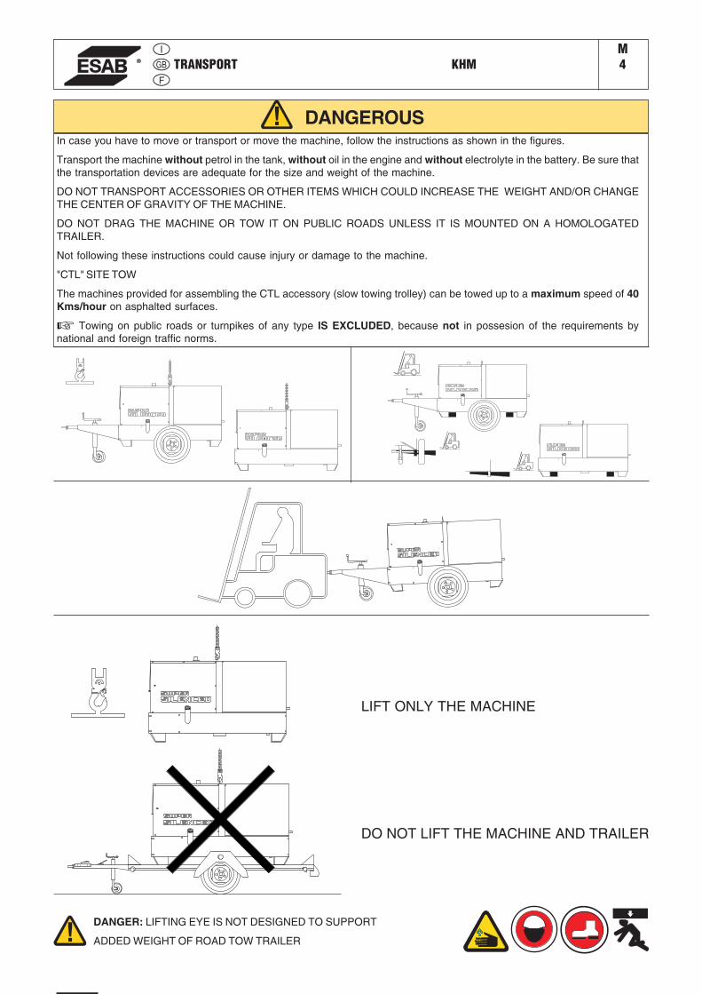
DANGEROUSIn case you have to move or transport or move the machine, follow the instructions as shown in the figures.
Transport the machine without petrol in the tank, without oil in the engine and without electrolyte in the battery. Be sure thatthe transportation devices are adequate for the size and weight of the machine.
DO NOT TRANSPORT ACCESSORIES OR OTHER ITEMS WHICH COULD INCREASE THE WEIGHT AND/OR CHANGETHE CENTER OF GRAVITY OF THE MACHINE.
DO NOT DRAG THE MACHINE OR TOW IT ON PUBLIC ROADS UNLESS IT IS MOUNTED ON A HOMOLOGATEDTRAILER.
Not following these instructions could cause injury or damage to the machine.
"CTL" SITE TOW
The machines provided for assembling the CTL accessory (slow towing trolley) can be towed up to a maximum speed of 40Kms/hour on asphalted surfaces.
☞ Towing on public roads or turnpikes of any type IS EXCLUDED, because not in possesion of the requirements bynational and foreign traffic norms.
DANGER: LIFTING EYE IS NOT DESIGNED TO SUPPORT
ADDED WEIGHT OF ROAD TOW TRAILER
DO NOT LIFT THE MACHINE AND TRAILER
LIFT ONLY THE MACHINE
ASSEMBLY KHM 351 YS BCKHM 405 YS
M6.2
16/0
1/08
M06
GB
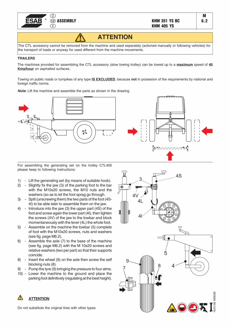
Nota: Lift the machine and assemble the parts as shown in the drawing
The CTL accessory cannot be removed from the machine and used separately (actioned manually or following vehicles) forthe transport of loads or anyway for used different from the machine movements.
For assembling the generating set on the trolley CTL400please keep to following instructions:
1) - Lift the generating set (by means of suitable hook).2) - Slightly fix the jaw (3) of the parking foot to the bar
with the M10x20 screws, the M10 nuts and thewashers (so as to let the foot sprag go through.
3) - Split (unscrewing them) the two parts of the foot (4S-4I) to be able later to assemble them on the jaw.
4) - Introduce into the jaw (3) the upper part (4S) of thefoot and screw again the lower part (4I), then tightenthe screws (4V) of the jaw to the towbar and blockmomentaneously with the lever (4L) the whole foot.
5) - Assemble on the machine the towbar (5) completeof foot with the M10x20 screws, nuts and washers(see fig. page M6.2).
6) - Assemble the axle (7) to the base of the machine(see fig. page M6.2) with the M 10x20 screws andrelative washers (two per part) so that their supportscoincide.
8) - Insert the wheel (9) on the axle then screw the selfblocking nuts (8).
9) - Pump the tyre (9) bringing the pressure to four atms.10) - Lower the machine to the ground and place the
parking foot definitively (regulating at the best height).
ATTENTION
Do not substitute the original tires with other types.
ATTENTION
4
5
34S
4I
4L
4V
78
9
TRAILERS
The machines provided for assembling the CTL accessory (slow towing trolley) can be towed up to a maximum speed of 40Kms/hour on asphalted surfaces.
Towing on public roads or turnpikes of any type IS EXCLUDED, because not in possesion of the requirements by national andforeign traffic norms.
PRECAUTION (ENGINE DRIVEN WELDER) KHMM
2.6
1,5m
1,5m
1,5
m
GAS DI SCARICO
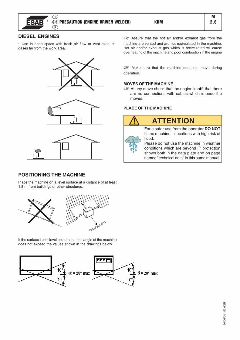
DIESEL ENGINES· Use in open space with fresh air flow or vent exhaustgases far from the work area.
POSITIONING THE MACHINEPlace the machine on a level surface at a distance of at least1,5 m from buildings or other structures.
If the surface is not level be sure that the angle of the machinedoes not exceed the values shown in the drawings below.
MOVES OF THE MACHINE☞ At any move check that the engine is off, that there
are no connections with cables which impede themoves.
PLACE OF THE MACHINE
ATTENTIONFor a safer use from the operator DO NOTfit the machine in locations with high risk offlood.Please do not use the machine in weatherconditions which are beyond IP protectionshown both in the data plate and on pagenamed "technical data" in this same manual.
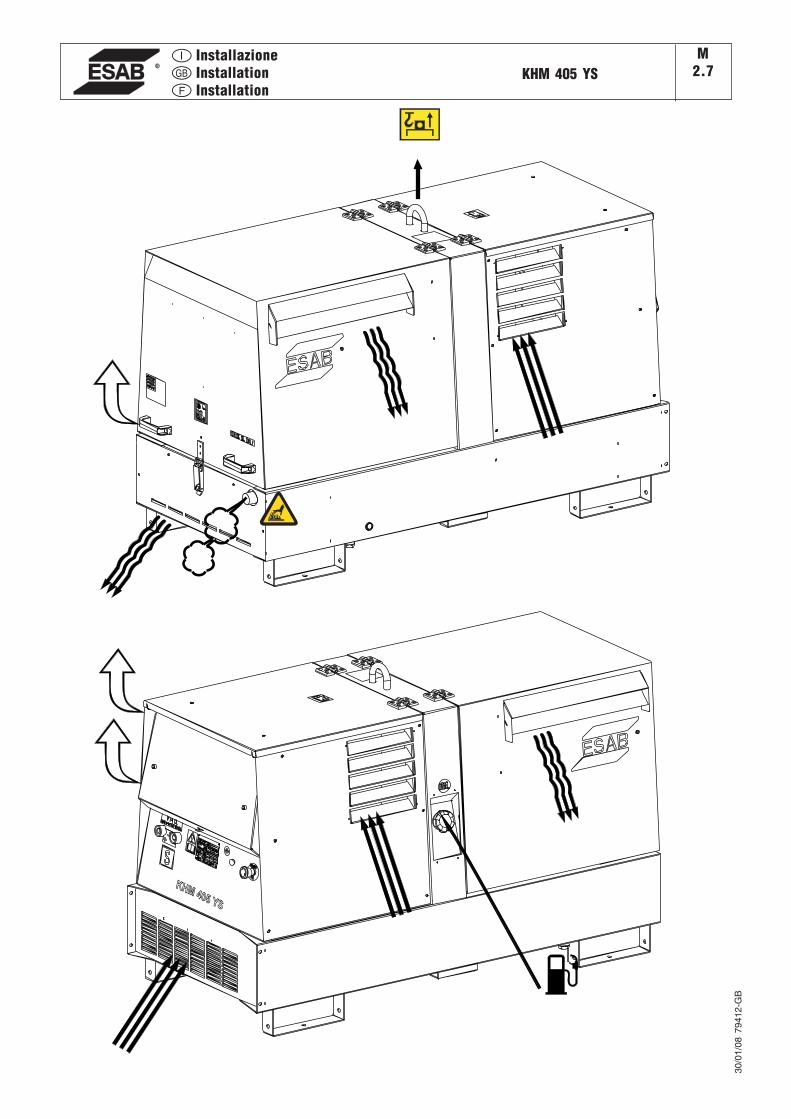
☞ Assure that the hot air and/or exhaust gas from the
machine are vented and are not recirculated in the machine.Hot air and/or exhaust gas which is recirculated wll causeoverheating of the machine and poor combustion in the engine
☞ Make sure that the machine does not move during
operation.
20/0
6/00
M2.
6GB
InstallazioneInstallationInstallation
KHM 405 YSM
2.7
KHM 405 YS
30/0
1/08
794
12-G
B
UNPACKING KHMM3
GENERAL PACKING INFORMATION
2
B
A1
C
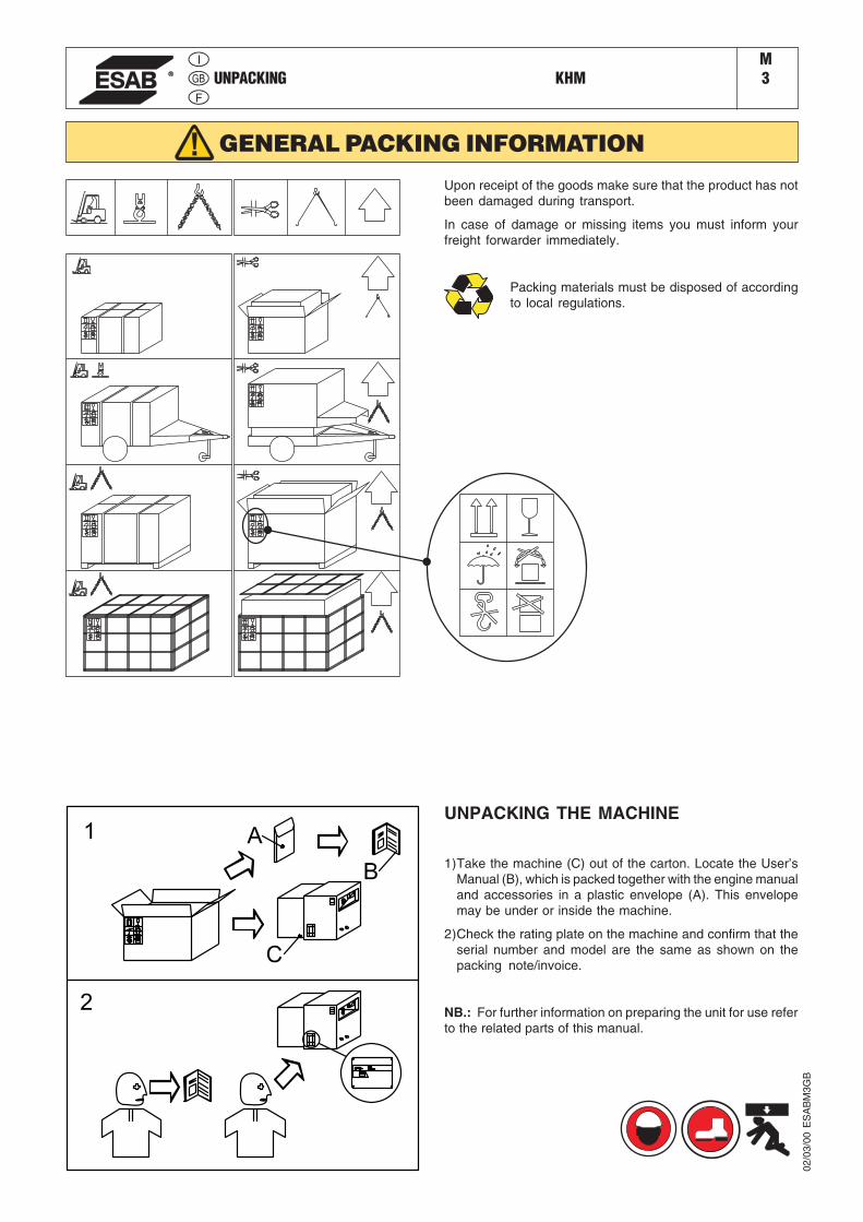
Upon receipt of the goods make sure that the product has notbeen damaged during transport.
In case of damage or missing items you must inform yourfreight forwarder immediately.
Packing materials must be disposed of accordingto local regulations.
UNPACKING THE MACHINE
1)Take the machine (C) out of the carton. Locate the User’sManual (B), which is packed together with the engine manualand accessories in a plastic envelope (A). This envelopemay be under or inside the machine.
2)Check the rating plate on the machine and confirm that theserial number and model are the same as shown on thepacking note/invoice.
NB.: For further information on preparing the unit for use referto the related parts of this manual.
02/0
3/00
ES
AB
M3G
B
KHM 405 YSM
1.5Technical data
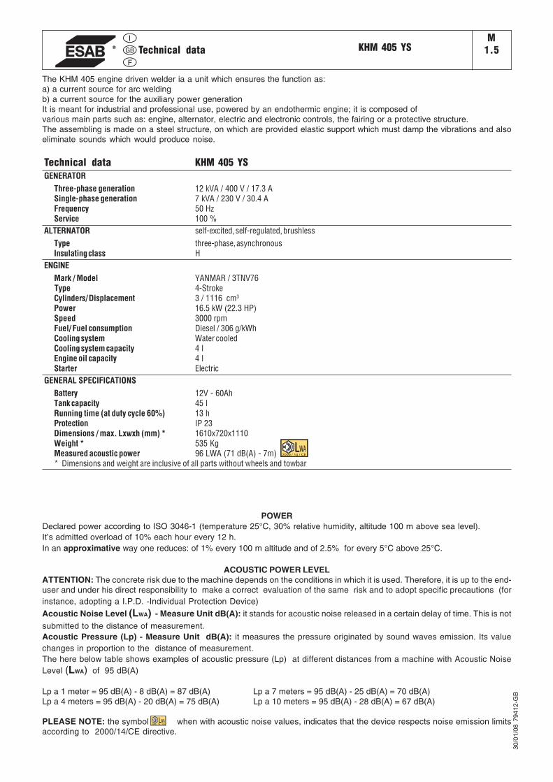
The KHM 405 engine driven welder ia a unit which ensures the function as:a) a current source for arc weldingb) a current source for the auxiliary power generationIt is meant for industrial and professional use, powered by an endothermic engine; it is composed ofvarious main parts such as: engine, alternator, electric and electronic controls, the fairing or a protective structure.The assembling is made on a steel structure, on which are provided elastic support which must damp the vibrations and alsoeliminate sounds which would produce noise.
Technical data KHM 405 YSGENERATOR
Three-phase generation 12 kVA / 400 V / 17.3 ASingle-phase generation 7 kVA / 230 V / 30.4 AFrequency 50 HzService 100 %
ALTERNATOR self-excited, self-regulated, brushlessType three-phase, asynchronousInsulating class H
ENGINEMark / Model YANMAR / 3TNV76
Type 4-StrokeCylinders/ Displacement 3 / 1116 cm3
Power 16.5 kW (22.3 HP)Speed 3000 rpmFuel/ Fuel consumption Diesel / 306 g/kWhCooling system Water cooledCooling system capacity 4 lEngine oil capacity 4 lStarter Electric
GENERAL SPECIFICATIONSBattery 12V - 60AhTank capacity 45 lRunning time (at duty cycle 60%) 13 hProtection IP 23Dimensions / max. Lxwxh (mm) * 1610x720x1110Weight * 535 KgMeasured acoustic power 96 LWA (71 dB(A) - 7m)* Dimensions and weight are inclusive of all parts without wheels and towbar
30/0
1/08
794
12-G
BPOWER
Declared power according to ISO 3046-1 (temperature 25°C, 30% relative humidity, altitude 100 m above sea level).It’s admitted overload of 10% each hour every 12 h.In an approximative way one reduces: of 1% every 100 m altitude and of 2.5% for every 5°C above 25°C.
ACOUSTIC POWER LEVELATTENTION: The concrete risk due to the machine depends on the conditions in which it is used. Therefore, it is up to the end-user and under his direct responsibility to make a correct evaluation of the same risk and to adopt specific precautions (forinstance, adopting a I.P.D. -Individual Protection Device)
Acoustic Noise Level (LWA) - Measure Unit dB(A): it stands for acoustic noise released in a certain delay of time. This is not
submitted to the distance of measurement.Acoustic Pressure (Lp) - Measure Unit dB(A): it measures the pressure originated by sound waves emission. Its valuechanges in proportion to the distance of measurement.The here below table shows examples of acoustic pressure (Lp) at different distances from a machine with Acoustic NoiseLevel (LWA) of 95 dB(A)
Lp a 1 meter = 95 dB(A) - 8 dB(A) = 87 dB(A) Lp a 7 meters = 95 dB(A) - 25 dB(A) = 70 dB(A)Lp a 4 meters = 95 dB(A) - 20 dB(A) = 75 dB(A) Lp a 10 meters = 95 dB(A) - 28 dB(A) = 67 dB(A)
PLEASE NOTE: the symbol when with acoustic noise values, indicates that the device respects noise emission limitsaccording to 2000/14/CE directive.
2000 / 14 / CE
2000 / 14 / CE
KHM 405 YSM
1.6Technical data
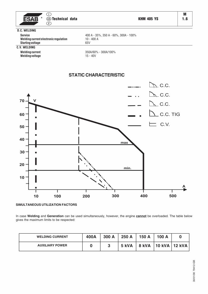
D.C. WELDINGService 400 A - 35%, 350 A - 60%, 300A - 100%Welding current electronic regulation 10 - 400 AStarting voltage 65V
C.V. WELDINGWelding current 350A/60% - 300A/100%Welding voltage 15 - 40V
30/0
1/08
794
12-G
B
SIMULTANEOUS UTILIZATION FACTORS
In case Welding and Generation can be used simultaneously, however, the engine cannot be overloaded. The table belowgives the maximum limits to be respected:
8 kVA5 kVA30AUXILIARY POWER
250 A300 A400AWELDING CURRENT 0150 A 100 A
10 kVA 12 kVA
100 200 300 400 500
A
V
10
20
30
40
50
60
70
10
min.
max
C.V.
C.C. TIG
C.C.
C.C.
C.C.
STATIC CHARACTERISTIC
PREPARING THE UNIT (DIESEL ENGINES) KHMM20
15/0
9/05
ES
AB
M20
GB
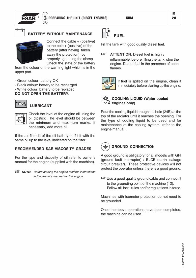
BATTERY WITHOUT MAINTENANCE
Connect the cable + (positive)to the pole + (positive) of thebattery (after having takenaway the protection), byproperly tightening the clamp.Check the state of the battery
from the colour of the warning light which is in theupper part.
- Green colour: battery OK- Black colour: battery to be recharged- White colour: battery to be replacedDO NOT OPEN THE BATTERY.
LUBRICANT
LIVELLO
OPERATIVO
ASTINA LIVELLO
OLIO
MAX
MIN
Check the level of the engine oil using theoil dipstick. The level should be betweenthe minimum and maximum marks. lfnecessary, add more oil.
If the air filter is of the oil bath type, fill it with thesame oil up to the level indicated on the filter.
RECOMMENDED SAE VISCOSITY GRADES
For the type and viscosity of oil refer to owner’smanual for the engine (supplied with the machine).
NOTE: Before starting the engine read the instructionsin the owner’s manual for the engine.
FUEL
Fill the tank with good quality diesel fuel.
☞ ATTENTION: Diesel fuel is highlyinflammable; before filling the tank, stop theengine. Do not fuel in the presence of openflames.
If fuel is spilled on the engine, clean itimmediately before starting up the engine.
COOLING LIQUID (Water-cooledengines only)
Pour the cooling liquid through the hole (24B) at thetop of the radiator until it reaches the opening. Forthe type of cooling liquid to be used and formaintenance of the cooling system, refer to theengine manual.
GROUND CONNECTION
A good ground is obligatory for all models with GFI(ground fault interrupter) / ELCB (earth leakagecircuit breaker). These protective devices will notprotect the operator unless there is a good ground.
☞ Use a good quality ground cable and connect itto the grounding point of the machine (12).Follow all local rules and/or regulations in force.
Machines with Isometer protection do not need tobe grounded.
Once the above operations have been completed,the machine can be used.
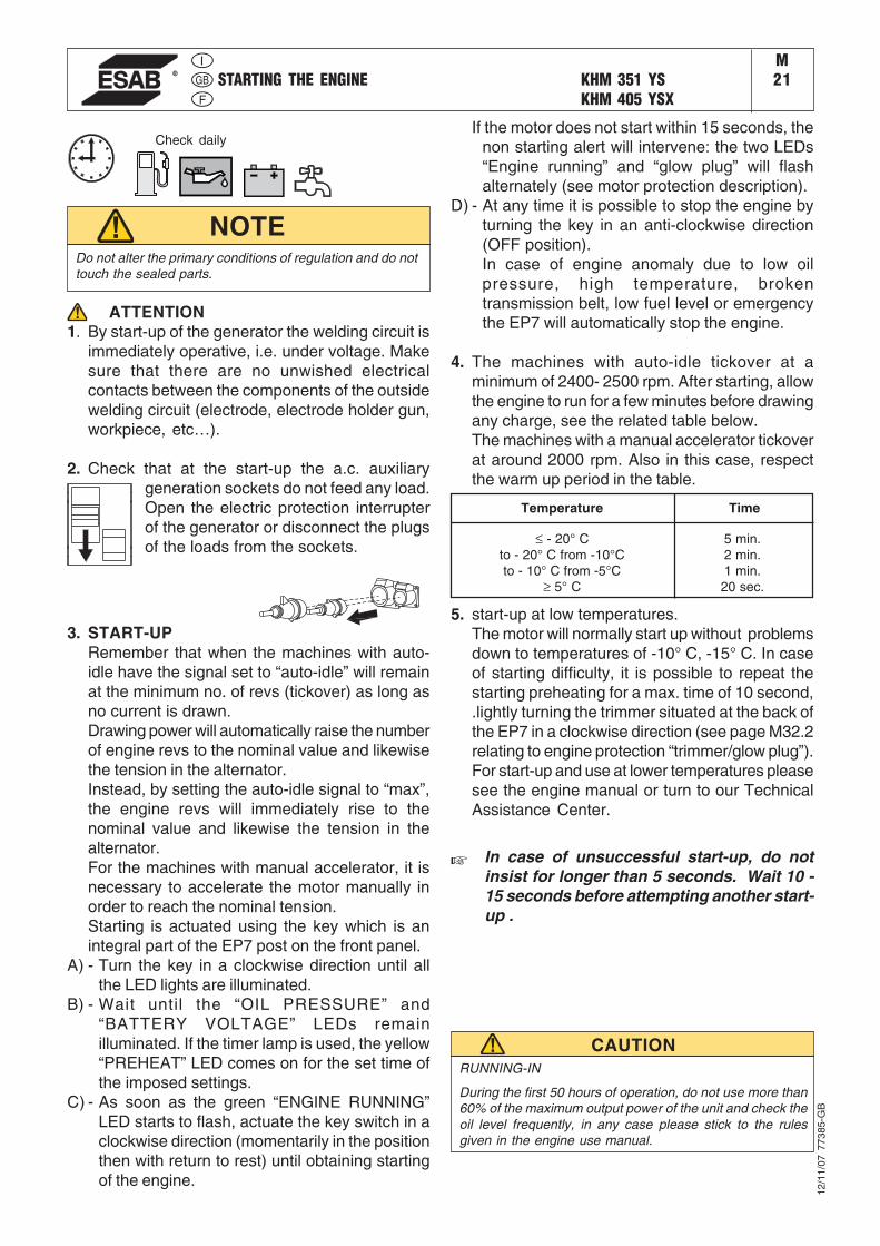
STARTING THE ENGINE KHM 351 YSKHM 405 YSX
M21
Temperature Time
≤ - 20° Cto - 20° C from -10°Cto - 10° C from -5°C
≥ 5° C
5 min.2 min.1 min.20 sec.
RUNNING-IN
During the first 50 hours of operation, do not use more than60% of the maximum output power of the unit and check theoil level frequently, in any case please stick to the rulesgiven in the engine use manual.
CAUTION
Do not alter the primary conditions of regulation and do nottouch the sealed parts.
NOTE
Check daily
ATTENTION1. By start-up of the generator the welding circuit is
immediately operative, i.e. under voltage. Makesure that there are no unwished electricalcontacts between the components of the outsidewelding circuit (electrode, electrode holder gun,workpiece, etc…).
2. Check that at the start-up the a.c. auxiliarygeneration sockets do not feed any load.Open the electric protection interrupterof the generator or disconnect the plugsof the loads from the sockets.
3. START-UPRemember that when the machines with auto-idle have the signal set to “auto-idle” will remainat the minimum no. of revs (tickover) as long asno current is drawn.Drawing power will automatically raise the numberof engine revs to the nominal value and likewisethe tension in the alternator.Instead, by setting the auto-idle signal to “max”,the engine revs will immediately rise to thenominal value and likewise the tension in thealternator.For the machines with manual accelerator, it isnecessary to accelerate the motor manually inorder to reach the nominal tension.Starting is actuated using the key which is anintegral part of the EP7 post on the front panel.
A) - Turn the key in a clockwise direction until allthe LED lights are illuminated.
B) - Wait until the “OIL PRESSURE” and“BATTERY VOLTAGE” LEDs remainilluminated. If the timer lamp is used, the yellow“PREHEAT” LED comes on for the set time ofthe imposed settings.
C) - As soon as the green “ENGINE RUNNING”LED starts to flash, actuate the key switch in aclockwise direction (momentarily in the positionthen with return to rest) until obtaining startingof the engine.
If the motor does not start within 15 seconds, thenon starting alert will intervene: the two LEDs“Engine running” and “glow plug” will flashalternately (see motor protection description).
D) - At any time it is possible to stop the engine byturning the key in an anti-clockwise direction(OFF position).In case of engine anomaly due to low oilpressure, high temperature, brokentransmission belt, low fuel level or emergencythe EP7 will automatically stop the engine.
4. The machines with auto-idle tickover at aminimum of 2400- 2500 rpm. After starting, allowthe engine to run for a few minutes before drawingany charge, see the related table below.The machines with a manual accelerator tickoverat around 2000 rpm. Also in this case, respectthe warm up period in the table.
5. start-up at low temperatures.The motor will normally start up without problemsdown to temperatures of -10° C, -15° C. In caseof starting difficulty, it is possible to repeat thestarting preheating for a max. time of 10 second,.lightly turning the trimmer situated at the back ofthe EP7 in a clockwise direction (see page M32.2relating to engine protection “trimmer/glow plug”).For start-up and use at lower temperatures pleasesee the engine manual or turn to our TechnicalAssistance Center.
In case of unsuccessful start-up, do notinsist for longer than 5 seconds. Wait 10 -15 seconds before attempting another start-up .
12/1
1/07
773
85-G
B
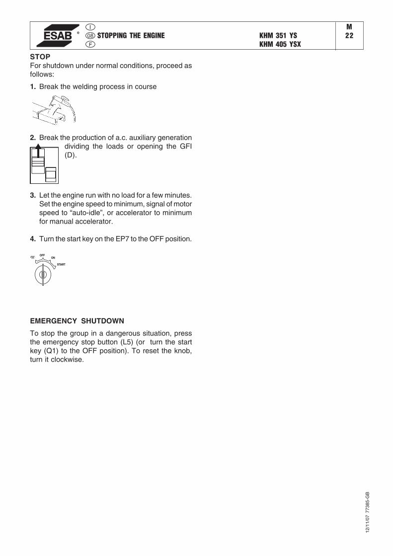
STOPPING THE ENGINE KHM 351 YSKHM 405 YSX
M22
STOPFor shutdown under normal conditions, proceed asfollows:
1. Break the welding process in course
OFFON
START
2. Break the production of a.c. auxiliary generationdividing the loads or opening the GFI(D).
3. Let the engine run with no load for a few minutes.Set the engine speed to minimum, signal of motorspeed to “auto-idle”, or accelerator to minimumfor manual accelerator.
4. Turn the start key on the EP7 to the OFF position.
EMERGENCY SHUTDOWN
To stop the group in a dangerous situation, pressthe emergency stop button (L5) (or turn the startkey (Q1) to the OFF position). To reset the knob,turn it clockwise.
12/1
1/07
773
85-G
B

30/0
1/08
794
12-G
B
ComandiControlsCommandes
KHM 405 YSM31
Pos. Descrizione Description Description91015
59A59B59CC2D
H8I3I8L5NMO8
Q7T
V4X1
Presa di saldatura (+)Presa di saldatura (-)Presa di corrente in c.a.Protezione termica motoreProtezione termica corrente auxProtezione termica alim.trainafilo 42VIndicatore livello combustibileInterruttore differenziale (30mA)Unità controllo motore EP7Commut. riduz. scala saldaturaSelettore AUTOIDLEPulsante stop emergenzaVoltmetroContaoreScheda strum. V/A digitalie scheda LED V.R.D.Selettore modalità saldaturaRegolatore corrente di saldaturaComando invertitore polaritàPresa per comando a distanza
Welding socket ( + )Welding socket ( - )A.C. socketEngine thermal switchAux current thermal switchSupply therm.switch wire feeder 42V
Fuel level lightG.F.I.Engine control unit EP7Welding scale switchAUTOIDLE switchEmergency buttonVoltmeteHour counterV/A digital instruments PCBand Led V.R.D. PCBWelding selector modeWelding current regulatorPolarity inverter controlRemote control socket
Prise de soudage ( + )Prise de soudage ( - )Prises de courant en c.a.Protection thermique moteurProtection thermique courant aux.Protection thermique alimentation 42V filIndicateur niveau carburantlnterrupteur différentielProtection moteur EP7Commutateur échelle soudageSelecteur AUTOIDLEBouton d’urgenceVoltmètreCompte-heuresPlatine Volt/Amp.-mètre digitaleet platine LED V.R.D.Sélecteur modalité soudageRégulateur courant soudageCommande inverseur polaritéPrise pour télécommande
ReferenzlisteSchweißbuchse (+)Schweißbuchse (-)Steckdose ACThermoschutz MotorThermoschutz HilfsstromThermoschutz DrahtvorschubAnzeige KraftstoffpegelFI-Schalter (GFI)Motorschutz EP7Bereichsschalter SchweißstromWahlschalter DrehzahlverstellungNotschalterVoltmeterStundenzählerPlatine-Digitale Anzeige Volt /Ampereund platine-Anzeige V.R.D.SchveißschalterSchweißstromreglerPolwendeschalterSteckdose Fernbedienung
15
910
12
L5
I8
59A
59B
H8C2DN
Q7
T
X1
I3
M
59CV4
(PL Version)
O8
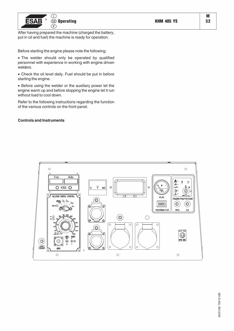
Operating KHM 405 YSM32
After having prepared the machine (charged the battery,put in oil and fuel) the machine is ready for operation.
Before starting the engine please note the following:
• The welder should only be operated by qualifiedpersonnel with experience in working with engine drivenwelders.
• Check the oil level daily. Fuel should be put in beforestarting the engine.
• Before using the welder or the auxiliary power let theengine warm up and before stopping the engine let it runwithout load to cool down.
Refer to the following instructions regarding the functionof the various controls on the front panel.
Controls and Instruments
30/0
1/08
794
12-G
B
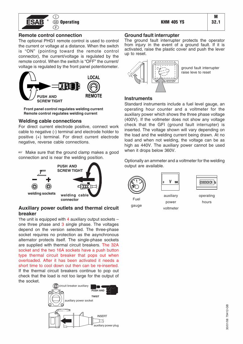
Operating KHM 405 YSM
32.1
Welding cable connectionsFor direct current electrode positive, connect workcable to negative (-) terminal and electrode holder topositive (+) terminal. For direct current electrodenegative, reverse cable connections.
☞ Make sure that the ground clamp makes a goodconnection and is near the welding posítion.
Auxiliary power outlets and thermal circuitbreakerThe unit is equipped with 4 auxiliary output sockets –one three phase and 3 single phase. The voltagesdepend on the version selected. The three-phasesocket requires no protection as the asynchronousalternator protects itself. The single-phase socketsare supplied with thermal circuit breakers. The 32Asocket and the two 16A sockets have a push buttontype thermal circuit breaker that pops out whenoverloaded. After it has been activated it needs ashort time to cool down out then can be re-inserted.If the thermal circuit breakers continue to pop outcheck that the load is not too large for the output ofthe socket.
PUSH ANDSCREW TIGHT
Front panel control regulates welding currentRemote control regulates welding current
LOCAL
REMOTE
ground fault interrupterraise leve to reset
PUSH ANDSCREW TIGHT
welding cableconnector
welding sockets
30/0
1/08
794
12-G
B
Ground fault interrupterThe ground fault interrupter protects the operatorfrom injury in the event of a ground fault. If it isactivated, raise the plastic cover and push the leverup to reset.
TO
PRESS RESET
CIRCUIT BREAKER
TO
PRESS RESET
CIRCUIT BREAKER
PUSH AND
TWIST
circuit breaker auxiliary
auxiliary power socket
INSERT
auxiliary power plug
4/4
½0
Fuel
gauge
operating
hours
auxiliary
power
voltmeter
Remote control connectionThe optional PHG1 remote control is used to controlthe current or voltage at a distance. When the switchis “ON” (pointing toward the remote controlconnector), the current/voltage is regulated by theremote control. When the switch is “OFF” the current/voltage is regulated by the front panel potentiometer.
InstrumentsStandard instruments include a fuel level gauge, anoperating hour counter and a voltmeter for theauxiliary power which shows the three phase voltage(400V). If the voltmeter does not show any voltagecheck that the GFI (ground fault interrupter) isinserted. The voltage shown will vary depending onthe load and the welding current being drawn. At noload and when not welding, the voltage can be ashigh as 440V. The auxiliary power cannot be usedwhen it drops below 360V.
Optionally an ammeter and a voltmeter for the weldingoutput are available.
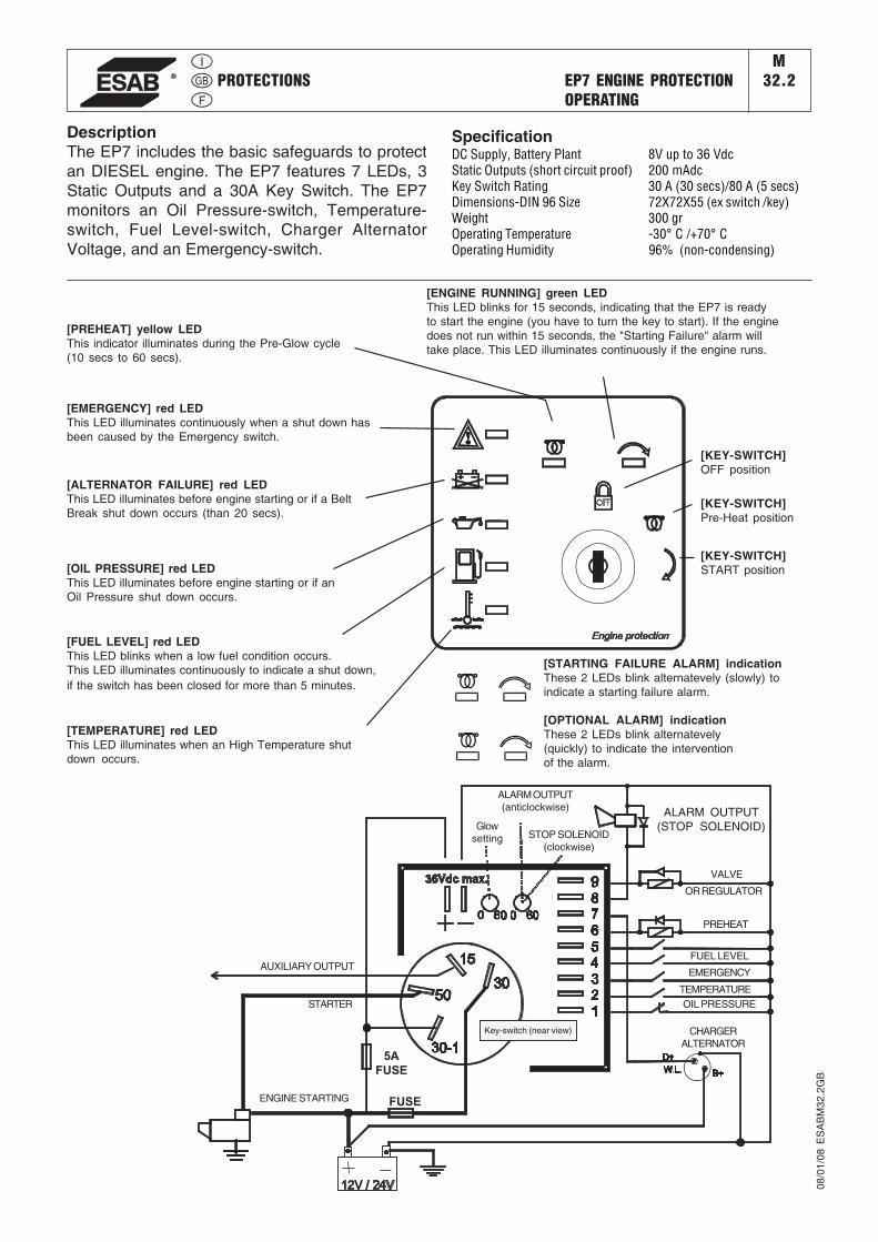
PROTECTIONS EP7 ENGINE PROTECTIONOPERATING
M32.2
08/0
1/08
ES
AB
M32
.2G
B
DescriptionThe EP7 includes the basic safeguards to protectan DIESEL engine. The EP7 features 7 LEDs, 3Static Outputs and a 30A Key Switch. The EP7monitors an Oil Pressure-switch, Temperature-switch, Fuel Level-switch, Charger AlternatorVoltage, and an Emergency-switch.
SpecificationDC Supply, Battery Plant 8V up to 36 VdcStatic Outputs (short circuit proof) 200 mAdcKey Switch Rating 30 A (30 secs)/80 A (5 secs)Dimensions-DIN 96 Size 72X72X55 (ex switch /key)Weight 300 grOperating Temperature -30° C /+70° COperating Humidity 96% (non-condensing)
[PREHEAT] yellow LEDThis indicator illuminates during the Pre-Glow cycle(10 secs to 60 secs).
[ALTERNATOR FAILURE] red LEDThis LED illuminates before engine starting or if a BeltBreak shut down occurs (than 20 secs).
[OIL PRESSURE] red LEDThis LED illuminates before engine starting or if anOil Pressure shut down occurs.
[FUEL LEVEL] red LEDThis LED blinks when a low fuel condition occurs.This LED illuminates continuously to indicate a shut down,if the switch has been closed for more than 5 minutes.
[TEMPERATURE] red LEDThis LED illuminates when an High Temperature shutdown occurs.
[ENGINE RUNNING] green LEDThis LED blinks for 15 seconds, indicating that the EP7 is readyto start the engine (you have to turn the key to start). If the enginedoes not run within 15 seconds, the "Starting Failure" alarm willtake place. This LED illuminates continuously if the engine runs.
[KEY-SWITCH]OFF position
[KEY-SWITCH]Pre-Heat position
[KEY-SWITCH]START position
5AFUSE
FUSE
[EMERGENCY] red LEDThis LED illuminates continuously when a shut down hasbeen caused by the Emergency switch.
Glowsetting
Key-switch (near view)
AUXILIARY OUTPUT
STARTER
ENGINE STARTING
STOP SOLENOID(clockwise)
VALVE
OR REGULATOR
ALARM OUTPUT(STOP SOLENOID)
PREHEAT
FUEL LEVEL
EMERGENCY
TEMPERATUREOIL PRESSURE
[STARTING FAILURE ALARM] indicationThese 2 LEDs blink alternatevely (slowly) toindicate a starting failure alarm.
[OPTIONAL ALARM] indicationThese 2 LEDs blink alternatevely(quickly) to indicate the interventionof the alarm.
ALARM OUTPUT(anticlockwise)
CHARGERALTERNATOR
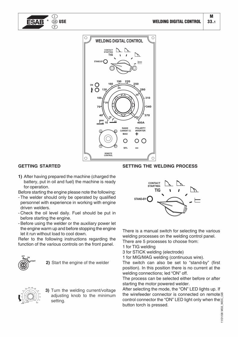
USE WELDING DIGITAL CONTROLM
33.1
GETTING STARTED
1) After having prepared the machine (charged thebattery, put in oil and fuel) the machine is readyfor operation.
Before starting the engine please note the following:- The welder should only be operated by qualifiedpersonnel with experience in working with enginedriven welders.
- Check the oil level daily. Fuel should be put inbefore starting the engine.
- Before using the welder or the auxiliary power letthe engine warm up and before stopping the enginelet it run without load to cool down.
Refer to the following instructions regarding thefunction of the various controls on the front panel.
2) Start the engine of the welder
OFFON
START
3) Turn the welding current/voltageadjusting knob to the minimumsetting.
SETTING THE WELDING PROCESS
11/0
1/08
M33
_WD
C_G
B
There is a manual switch for selecting the variouswelding processes on the welding control panel.There are 5 processes to choose from:1 for TIG welding3 for STICK welding (electrode)1 for MIG/MAG welding (continuous wire).The switch can also be set to “stand-by” (firstposition). In this position there is no current at thewelding connections; led “ON” off.The process can be selected either before or afterstarting the motor powered welder.After selecting the mode, the “ON” LED lights up. Ifthe wirefeeder connector is connected on remotecontrol connector the “ON” LED light only when thebutton torch is pressed.
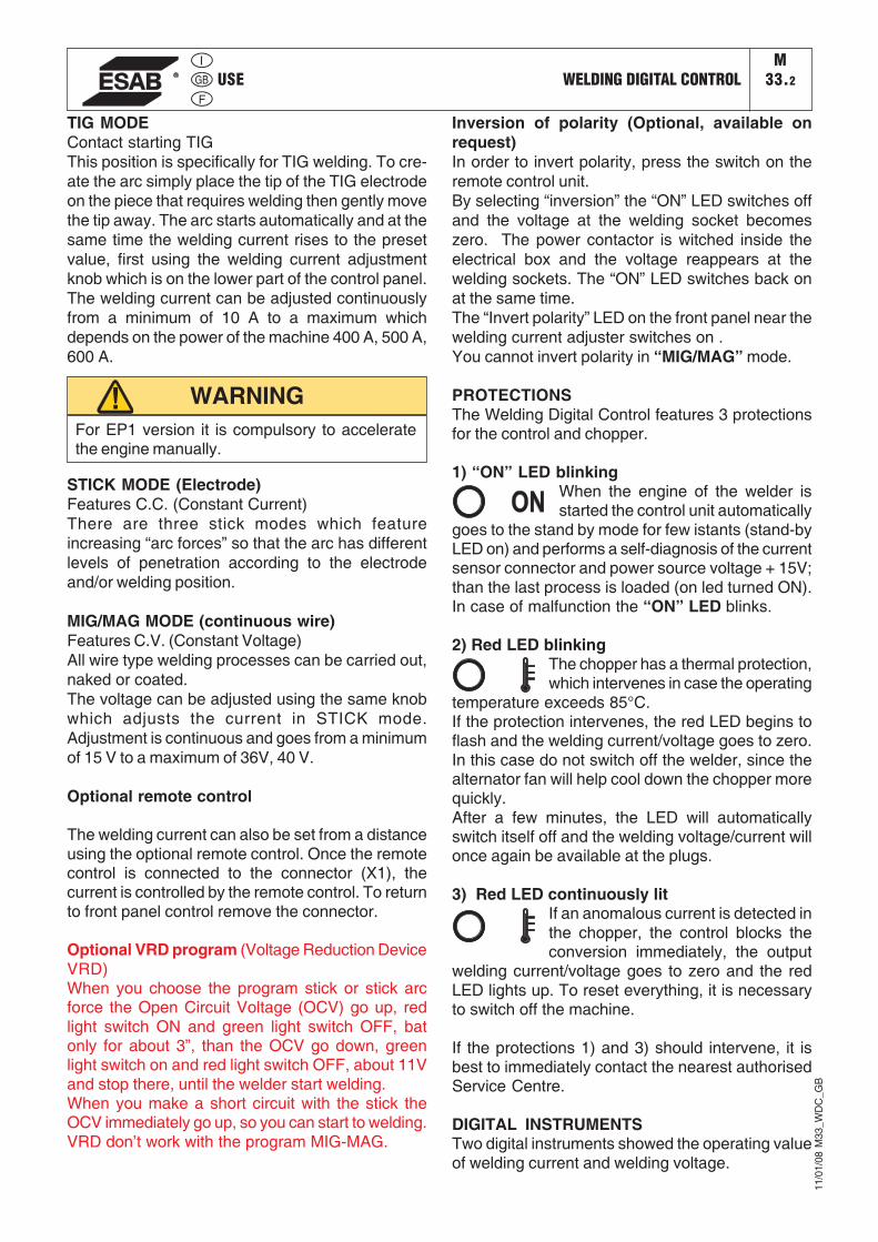
USE WELDING DIGITAL CONTROLM
33.2
TIG MODEContact starting TIGThis position is specifically for TIG welding. To cre-ate the arc simply place the tip of the TIG electrodeon the piece that requires welding then gently movethe tip away. The arc starts automatically and at thesame time the welding current rises to the presetvalue, first using the welding current adjustmentknob which is on the lower part of the control panel.The welding current can be adjusted continuouslyfrom a minimum of 10 A to a maximum whichdepends on the power of the machine 400 A, 500 A,600 A.
11/0
1/08
M33
_WD
C_G
B
Inversion of polarity (Optional, available onrequest)In order to invert polarity, press the switch on theremote control unit.By selecting “inversion” the “ON” LED switches offand the voltage at the welding socket becomeszero. The power contactor is witched inside theelectrical box and the voltage reappears at thewelding sockets. The “ON” LED switches back onat the same time.The “Invert polarity” LED on the front panel near thewelding current adjuster switches on .You cannot invert polarity in “MIG/MAG” mode.
PROTECTIONSThe Welding Digital Control features 3 protectionsfor the control and chopper.
1) “ON” LED blinkingWhen the engine of the welder isstarted the control unit automatically
goes to the stand by mode for few istants (stand-byLED on) and performs a self-diagnosis of the currentsensor connector and power source voltage + 15V;than the last process is loaded (on led turned ON).In case of malfunction the “ON” LED blinks.
2) Red LED blinkingThe chopper has a thermal protection,which intervenes in case the operating
temperature exceeds 85°C.If the protection intervenes, the red LED begins toflash and the welding current/voltage goes to zero.In this case do not switch off the welder, since thealternator fan will help cool down the chopper morequickly.After a few minutes, the LED will automaticallyswitch itself off and the welding voltage/current willonce again be available at the plugs.
3) Red LED continuously litIf an anomalous current is detected inthe chopper, the control blocks theconversion immediately, the output
welding current/voltage goes to zero and the redLED lights up. To reset everything, it is necessaryto switch off the machine.
If the protections 1) and 3) should intervene, it isbest to immediately contact the nearest authorisedService Centre.
DIGITAL INSTRUMENTSTwo digital instruments showed the operating valueof welding current and welding voltage.
For EP1 version it is compulsory to acceleratethe engine manually.
WARNING
STICK MODE (Electrode)Features C.C. (Constant Current)There are three stick modes which featureincreasing “arc forces” so that the arc has differentlevels of penetration according to the electrodeand/or welding position.
MIG/MAG MODE (continuous wire)Features C.V. (Constant Voltage)All wire type welding processes can be carried out,naked or coated.The voltage can be adjusted using the same knobwhich adjusts the current in STICK mode.Adjustment is continuous and goes from a minimumof 15 V to a maximum of 36V, 40 V.
Optional remote control
The welding current can also be set from a distanceusing the optional remote control. Once the remotecontrol is connected to the connector (X1), thecurrent is controlled by the remote control. To returnto front panel control remove the connector.
Optional VRD program (Voltage Reduction DeviceVRD)When you choose the program stick or stick arcforce the Open Circuit Voltage (OCV) go up, redlight switch ON and green light switch OFF, batonly for about 3”, than the OCV go down, greenlight switch on and red light switch OFF, about 11Vand stop there, until the welder start welding.When you make a short circuit with the stick theOCV immediately go up, so you can start to welding.VRD don’t work with the program MIG-MAG.
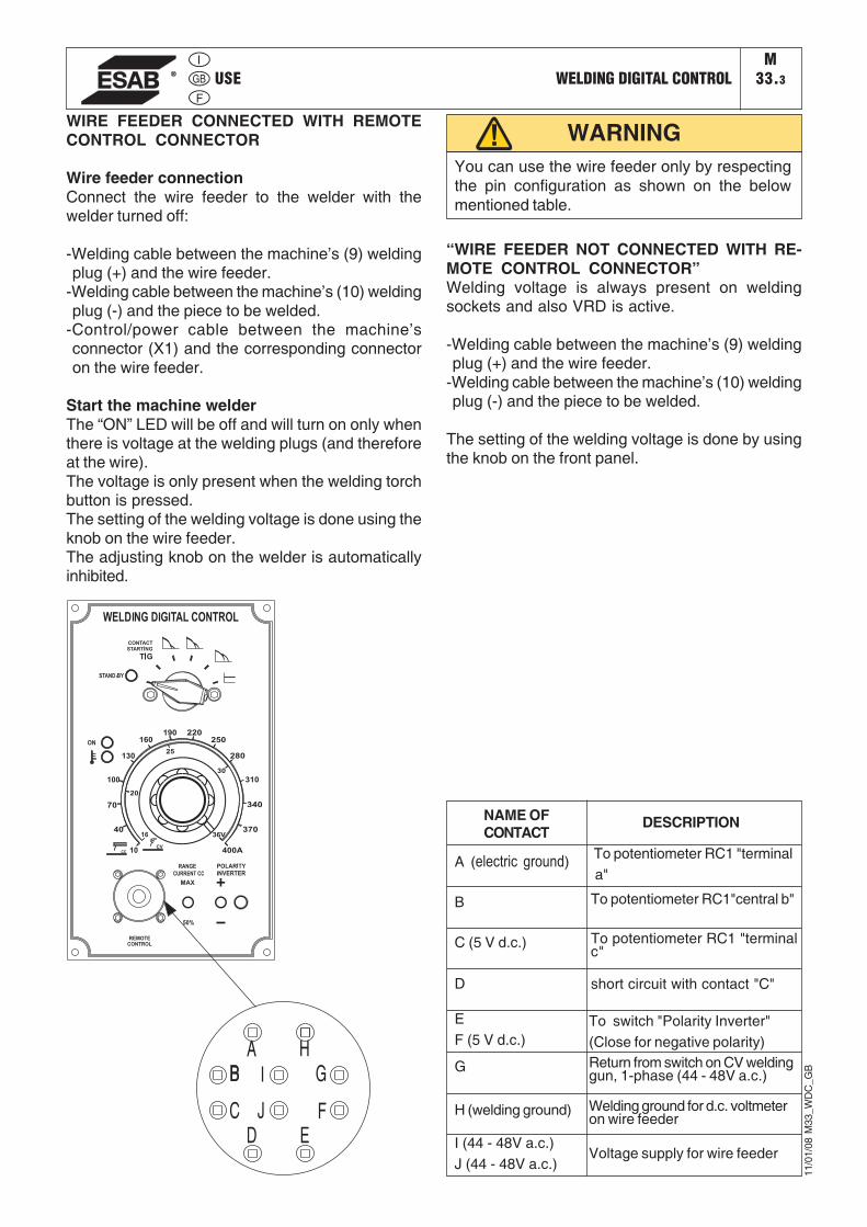
USE WELDING DIGITAL CONTROLM
33.3
WIRE FEEDER CONNECTED WITH REMOTECONTROL CONNECTOR
Wire feeder connectionConnect the wire feeder to the welder with thewelder turned off:
-Welding cable between the machine’s (9) weldingplug (+) and the wire feeder.
-Welding cable between the machine’s (10) weldingplug (-) and the piece to be welded.
-Control/power cable between the machine’sconnector (X1) and the corresponding connectoron the wire feeder.
Start the machine welderThe “ON” LED will be off and will turn on only whenthere is voltage at the welding plugs (and thereforeat the wire).The voltage is only present when the welding torchbutton is pressed.The setting of the welding voltage is done using theknob on the wire feeder.The adjusting knob on the welder is automaticallyinhibited.
You can use the wire feeder only by respectingthe pin configuration as shown on the belowmentioned table.
WARNING
A (electric ground)
B
C (5 V d.c.)
D
EF (5 V d.c.)
G
H (welding ground)
I (44 - 48V a.c.)J (44 - 48V a.c.)
DESCRIPTION
To potentiometer RC1 "terminal a"
To potentiometer RC1"central b"
To potentiometer RC1 "terminalc"
short circuit with contact "C"
NAME OFCONTACT
To switch "Polarity Inverter"(Close for negative polarity)Return from switch on CV weldinggun, 1-phase (44 - 48V a.c.)
Welding ground for d.c. voltmeteron wire feeder
Voltage supply for wire feeder
11/0
1/08
M33
_WD
C_G
B
“WIRE FEEDER NOT CONNECTED WITH RE-MOTE CONTROL CONNECTOR”Welding voltage is always present on weldingsockets and also VRD is active.
-Welding cable between the machine’s (9) weldingplug (+) and the wire feeder.
-Welding cable between the machine’s (10) weldingplug (-) and the piece to be welded.
The setting of the welding voltage is done by usingthe knob on the front panel.
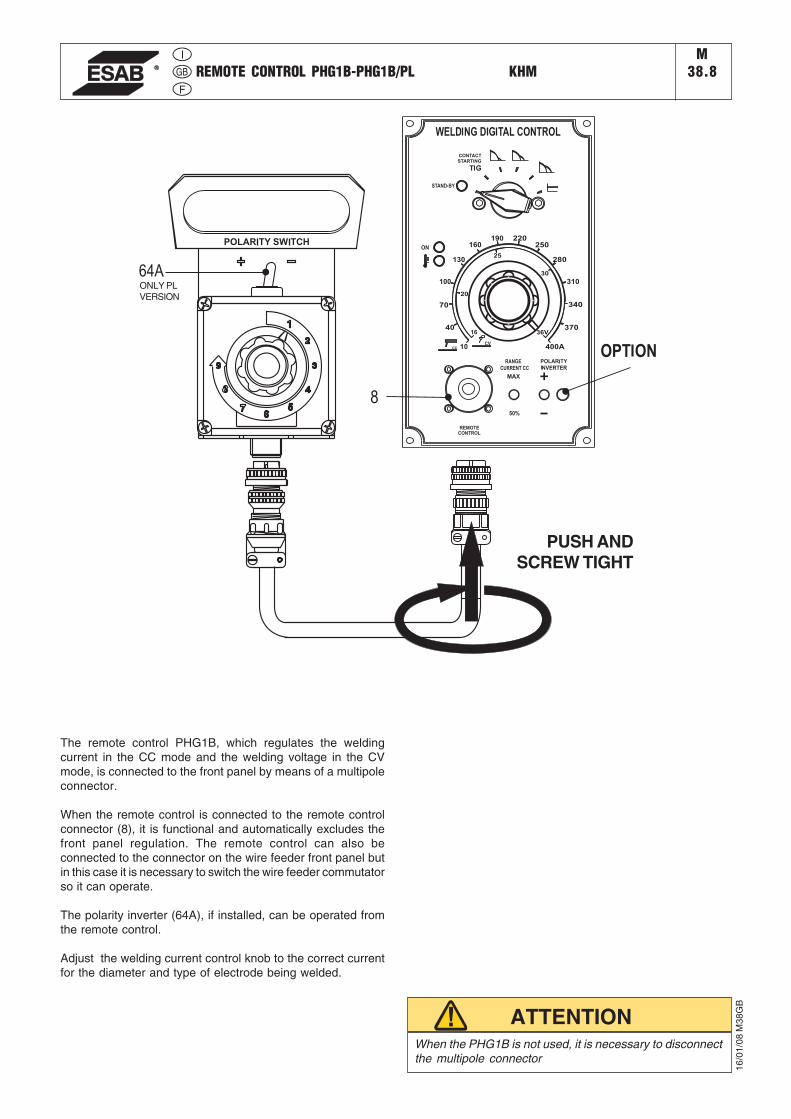
REMOTE CONTROL PHG1B-PHG1B/PL KHMM
38.8
16/0
1/08
M38
GB
PUSH ANDSCREW TIGHT
ONLY PLVERSION
When the PHG1B is not used, it is necessary to disconnectthe multipole connector
ATTENTION
The remote control PHG1B, which regulates the weldingcurrent in the CC mode and the welding voltage in the CVmode, is connected to the front panel by means of a multipoleconnector.
When the remote control is connected to the remote controlconnector (8), it is functional and automatically excludes thefront panel regulation. The remote control can also beconnected to the connector on the wire feeder front panel butin this case it is necessary to switch the wire feeder commutatorso it can operate.
The polarity inverter (64A), if installed, can be operated fromthe remote control.
Adjust the welding current control knob to the correct currentfor the diameter and type of electrode being welded.
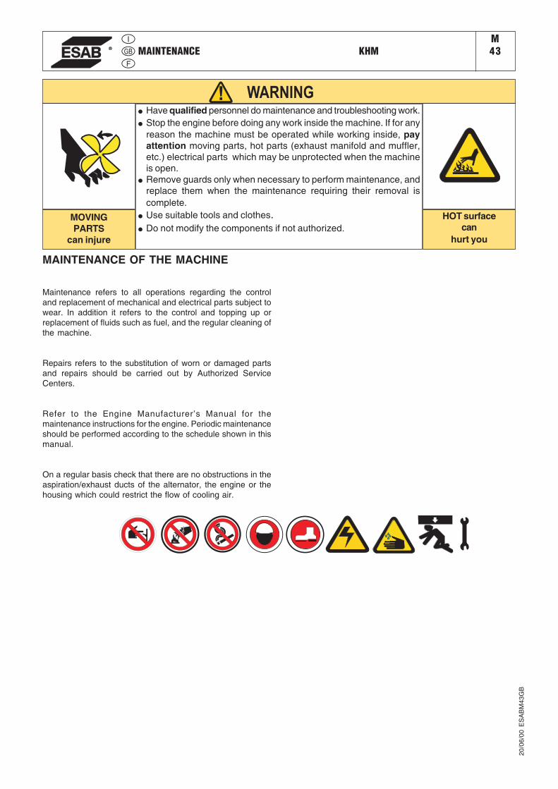
MAINTENANCE KHMM43
20/0
6/00
ES
AB
M43
GB
WARNING● Have qualified personnel do maintenance and troubleshooting work.● Stop the engine before doing any work inside the machine. If for any
reason the machine must be operated while working inside, payattention moving parts, hot parts (exhaust manifold and muffler,etc.) electrical parts which may be unprotected when the machineis open.
● Remove guards only when necessary to perform maintenance, andreplace them when the maintenance requiring their removal iscomplete.
● Use suitable tools and clothes.● Do not modify the components if not authorized.
HOT surfacecan
hurt you
MOVINGPARTS
can injure
MAINTENANCE OF THE MACHINE
Maintenance refers to all operations regarding the controland replacement of mechanical and electrical parts subject towear. In addition it refers to the control and topping up orreplacement of fluids such as fuel, and the regular cleaning ofthe machine.
Repairs refers to the substitution of worn or damaged partsand repairs should be carried out by Authorized ServiceCenters.
Refer to the Engine Manufacturer’s Manual for themaintenance instructions for the engine. Periodic maintenanceshould be performed according to the schedule shown in thismanual.
On a regular basis check that there are no obstructions in theaspiration/exhaust ducts of the alternator, the engine or thehousing which could restrict the flow of cooling air.

MAINTENANCE KHMM
43.3
BATTERY WITHOUT MAINTENANCE
DO NOT OPEN THE BATTERY
The battery is charged automatically from the battery chargercircuit supplied with the engine.
Check the state of the battery from the colour of the warninglight which is in the upper part.
- Green colour: battery OK- Black colour: battery to be recharged- White colour: battery to be replaced
DRY AIR FILTERReplace the air filter cartridge every 200 hours under normalconditions and every 100 hours in dusty environents.
RADIATORCheck the liquid level in the radiator regularly and refill asrequired. In the fall check the amount of antifreeze and addrequired to prevent freezing during the winter months.
ASYNCHRONOUS ALTERNATORNo maintenance is necessary, as the alternator has no brushesor slip rings, and there are no devices for regulation of theoutput.
WARNING LABELS AND DECALSCheck warning labels and decals once a year and replaced ifmissing or unreadable.
CABLES AND CONNECTIONSPeriodically check the condition of the cables and tighten theconnections.
IMPORTANTWhen carrying out maintenance operations becareful to avoid polluting the environment withthe materials used during maintenance. Followall local health and safety regulations.
15/0
9/05
ES
AB
M43
.3G
B
STORAGE KHMM45
20/0
6/00
ES
AB
M45
GB
In case the machine will not be used for more than 30 days, itshould be stored in a suitable area where it is protected fromthe elements to prevent rusting, corrosion and other damageto the machine.
DIESEL ENGINES
If the machine will be stored for short periods of time it isadvisable to start the engine every 10 days and operate it for15-30 minutes under load. This will distribute the oil, rechargethe battery and prevent blockage of the injection system.
For long periods of storage, refer to the engine manufacturer’smanual.
Clean the machine carefully.
Cover the machine with a plastic cover and store in a dryplace.
IMPORTANTWhen carrying out the operations to prepare the machinefor storage, be careful to avoid polluting the environmentwith the materials used during maintenance. Follow alllocal health and safety regulations.
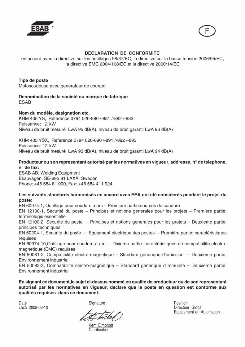
F
DECLARATION DE CONFORMITE'en accord avec la directive sur les outillages 98/37/EC, la directive sur la basse tension 2006/95/EC,
la directive EMC 2004/108/EC et la directive 2000/14/EC
Tipe de posteMotosoudeuse avec generateur de courant
Denomination de la societé ou marque de fabriqueESAB
Nom du modèle, designation etc.KHM 405 YS, Reference 0794 020-880 /-881 /-882 /-883Puissance: 12 kWNiveau de bruit mesuré LwA 95 dB(A), niveau de bruit garanti LwA 96 dB(A)
KHM 405 YSX, Reference 0794 020-890 /-891 /-892 /-893Puissance: 12 kWNiveau de bruit mesuré LwA 93 dB(A), niveau de bruit garanti LwA 94 dB(A)
Producteur ou son representant autorisé par les normatives en vigueur, addresse, n° de telephone,n° de fax:ESAB AB, Welding EquipmentEsabvägen, SE-695 81 LAXÅ, SwedenPhone: +46 584 81 000, Fax: +46 584 411 924
Les suivants standards harmonisés en accord avec EEA ont etè considerés pendant le projet duposte:EN 60974-1, Outillage pour soudure à arc – Premiére partie:sources de soudureEN 12100-1, Securité du poste – Principes et notions generales pour les projets – Premiére partie:terminologie essentielleEN 12100-2, Securité du poste – Principes et notions generales pour les projets – Deuxieme partie:principes techniquesEN 60204-1, Securité du poste – Equipment electrique des postes – Premiére partie: caractéristiquesrequisesEN 60974-10,Outillage pour soudure à arc – Dixieme partie: caractéristiques de compatibilite electro-magnetique (EMC) requisesEN 50081-2, Compatibilite electro-magnetique – Standard generique d'emission – Deuxieme partie:Environnement industrielEN 50082-2, Compatibilite electro-magnetique – Standard generique d'immunité – Deuxieme partie:Environnement industriel
En signant ce document,le sujet ci-dessus nommé,en qualité de producteur ou de son representantautorisé par les normatives en vigueur, declare que le poste en question est conforme auxqualités requises dans ce document.
Date Signature PositionLaxå 2008-03-10 Directeur Global
Equipement et Automation
Kent EimbrodtClarification
KHM 405 YSM1
Index
Cher Client,
Nous désirons vous remercier pour avoir acheté ce produit.
Veuillez bien prendre le temps de lire ce manuel et de vous familiariser avec la machine avant d’essayerde l’utiliser.
Si vous aviez des questions ou des problèmes, veuillez bien contacter le Service Assistance autorisé leplus proche. Ils ont l’expérience et les pièces de rechange d’origine. L’emploi de pièces qui ne sont pasd’origine annule la garantie.
INDEX
DESCRIPTION PAGENFORMATIONS GENERALESINFORMATIONS SUR CE MANUEL M 2DESCRIPTION DES SYMBOLES M 2.1PRECAUTIONS EN GENERAL M 2.5PRECAUTIONS POUR SOUDEUSES M 2.5.1TRANSPORT M 4MONTAGE CHARIOT M 6.2INFORMATIONS SUR L’INSTALLATION M 2.6, M 2.7
OPERATIONSDEBALLAGE M 3DONNEES TECHNIQUES & DESCRIPTION MACHINE M 1.5, M 1.6PREPARATION DU GROUPE M 20DEMARRAGE DU MOTEUR M 21ARRET DU MOTEUR M 22COMMANDES M 31UTILISATION DE LA INSTRUMENTATION M 32...UTILISATION - WELDING DIGITAL CONTROL M 33...TELECOMMANDE PHG1B-PHG1B/PL M 38.8ENTRETIEN M 43, M 43.3MAGASINAGE M 45DIMENSIONS M 53
SCHEMASDIAGRAMME CABLAGES:MOTEUR M 61.1AUXILIAIRE 400T/ 230Mx2 DT M 61.2PUISSANCE SOUDAGE M 61.3CONTROLE SOUDAGE M 61.4
30/0
1/08
794
12-F
����������������/
�������������������
�����������0������
���������0����
��������������������
�������������
��0���������������������������������������
�����������������������- Dans l’enveloppe où vous avez trouvé ce manuel
vous trouverez aussi un manuel pour le moteur, et accessoires (si demandés).
�Ce produit a été projeté pour soudage et génération de puissance électrique pour outils et autres appareils électriques utilisés dans le bâtiment; TOUT AUTRE USAGE n’est pas permis et nous ne pouvons pas etre tenus responsables pour blessures ou dommages résultant d’un emploi incorrect.
Nos produits sont fabriqués en conformité avec les normes de sécurité en vigueur afin d’éviter de blesser les personnes ou d’endommager la machine ou d’autres choses.
�� ���#���������1�'��2�'�(�"� ��'���""���1�'��2�'��3�"�'3��2�������#���� 1���'��(�*�����)��'3�����.�
Faire des modifications à la machine sans notre autorisation écrite annulera la garantie et nous dédouanera de toute responsabilité.�������4��������������
Avant d’utiliser la machine veuillez bien lire attentivement ce manuel et suivre les instructions qui y sont contenues. Ceci vous aidera à éviter des problèmes, blessures possibles et dommages à la machine.
Le manuel est écrit pour du personnel expérimenté et qualifié, qui est familiarisé avec les lois sur la santé et la sécurité et les règlements y-relatifs.
Ce manuel fait partie intégrante du produit et doit être tenu en lieu sûr pour pouvoir être consulté tant que dure le produit. Si la machine est vendue, le manuel doit être transféré au nouveau propriétaire.
Quelques figures contenues dans ce manuel sont destinées à aider à identifier certaines pièces et peuvent ne pas correspondre à la machine en votre possession.
� �3!):�/��$ ���� ���0���� 00�������� �1���� �����������$�� ����� ��0���������2��� ���������������������1����� ������ ������ ������������� �����2�3������
����
������/��1�������
Les en-têtes utilisés dans ce manuel sont destinés à appeler votre attention sur les hasards possibles et les aspects importants des opérations de la machine
Indique une forte possibilité de grave blessure personnelle ou mort si les instructions ne sont pas suivies.
Indique une possibilité de blessure à des personnes ou dommage à l’équipement si les instructions ne sont pas suivies.
Indique que des dommages à l’équipement ou à la propriété peuvent résulter si les instructions ne sont pas suivies.
Ces titres donnent des informations utiles sur la préparation, l’opération et le soin de la machine.
�2
10/1
/01
ES
AB
M2F
��
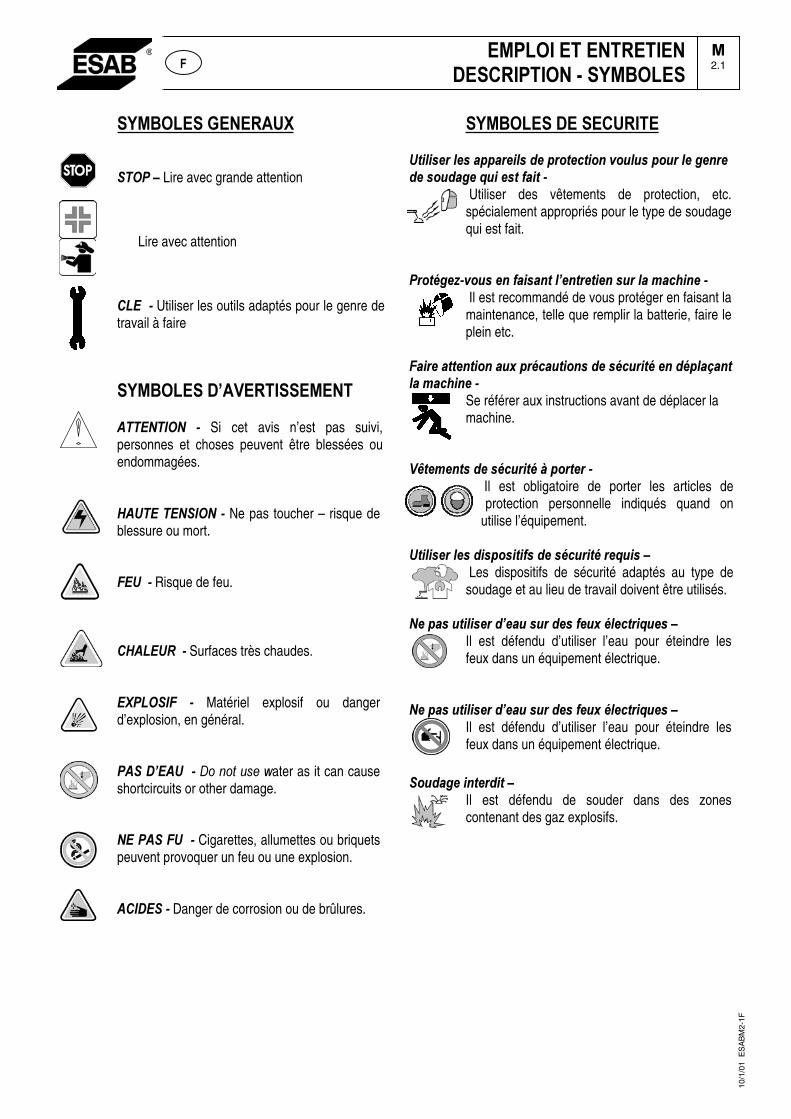
��� ����������
�����Lire avec grande attention
Lire avec attention
������Utiliser les outils adaptés pour le genre de travail à faire
��� ���������������
���������� � Si cet avis n’est pas suivi, personnes et choses peuvent être blessées ou endommagées.
������������� � Ne pas toucher – risque de blessure ou mort.��������� Risque de feu.
���������� Surfaces très chaudes. �
�������� �� Matériel explosif ou danger d’explosion, en général. ������;�����������������!ater as it can cause shortcircuits or other damage. ��������������Cigarettes, allumettes ou briquets peuvent provoquer un feu ou une explosion.�
��������Danger de corrosion ou de brûlures.
����
��� �������������!+.+$)%�.)$�#22#%)+.$�-)�2%3!)�!+3��,3 . $�23 %�.)�')�%)�-)�$3 -#')�< +�)$!�4#+!���
�Utiliser des vêtements de protection, etc. spécialement appropriés pour le type de soudage qui est fait.
�%3!=')"�,3 $�)��4#+$#�!�.;)�!%)!+)��$ %�.#��#��+�)���
Il est recommandé de vous protéger en faisant la maintenance, telle que remplir la batterie, faire le plein etc.
�#+%)�#!!)�!+3��# >�2%=�# !+3�$�-)�$=� %+!=�)��-=2.#?#�!�.#��#��+�)���
Se référer aux instructions avant de déplacer la machine.
���@!)�)�!$�-)�$=� %+!=�A�23%!)%���
Il est obligatoire de porter les articles de protection personnelle indiqués quand on
utilise l’équipement.
�!+.+$)%�.)$�-+$23$+!+4$�-)�$=� %+!=�%)< +$��� Les dispositifs de sécurité adaptés au type de soudage et au lieu de travail doivent être utilisés.
�)�2#$� !+.+$)%�-;)# �$ %�-)$�4) >�=.)�!%+< )$���Il est défendu d’utiliser l’eau pour éteindre les feux dans un équipement électrique.
�)�2#$� !+.+$)%�-;)# �$ %�-)$�4) >�=.)�!%+< )$���Il est défendu d’utiliser l’eau pour éteindre les feux dans un équipement électrique.
�3 -#')�+�!)%-+!���
Il est défendu de souder dans des zones contenant des gaz explosifs.
10/1
/01
ES
AB
M2-
1F
���� �������������������� ����� ��
�2.1�
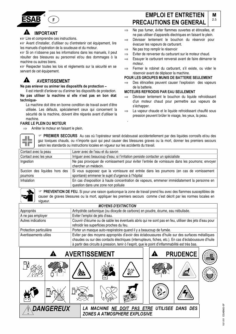
� �/01������� Lire et comprendre ces instructions. � Avant d’installer, d’utiliser ou d’entretenir cet équipement, lire les manuels d’opération de la soudeuse et du moteur.� Si on n’observe pas les informations dans les manuels, il peut résulter des blessures au personnel et/ou des dommages ò la machine ou autres biens. � Respecter toutes les lois et règlements sur la sécurité en se servant de cet équipement.
������2�������/��������� �������� ��������������������������� �3�
Il est interdit d’enlever ou d’animer les dispositifs de protection. �� ��� �������� ��� ����� � ��� ��� 4��� ��� � �� � 5������� �6���
La machine doit être en bonne condition de travail avant d’être utilisée. Les défauts, spécialement ceux qui concernent la sécurité de la machine, doivent être réparés avant d’utiliser la machine.
���������0��������/1�����⇒ Arrêter le moteur en faisant le plein.
⇒ Ne pas fumer, éviter flammes ouvertes et étincelles, et ne pas utiliser d’appareils électriques en faisant le plein.
⇒ Dévisser lentement le bouchon du réservoir pour évacuer les vapeurs de carburant.
⇒ Ne pas trop remplir le réservoir⇒ Eviter de renverser du carburant sur le moteur chaud. ⇒ Essuyer le carburant renversé avant de faire démarrer le
moteur.⇒ Fermer le robinet du carburant, s’il existe, ou vider le
réservoir avant de déplacer la machine. 01���������1�0���/���������������������/����⇒ Des étincelles peuvent causer l’explosion des vapeurs
de la batterie. /1���������1�����0����������/����⇒ Dévisser lentement le bouchon du liquide refroidissant
d’un moteur chaud pour permettre aux vapeurs de s’échapper.
⇒ La vapeur chaude et le liquide refroidissant chauffé sous pression peuvent brûler le visage, les yeux, la peau.
.
��0��/�������1���� Au cas où l’opérateur serait éclaboussé accidentellement par des liquides corrosifs et/ou des gaz toxiques chauds, ou n’importe quoi qui peut causer des blessures graves ou la mort, donner les premiers secours selon les standards ou instructions locales en vigueur sur les accidents du travail.
Contact avec la peau Laver avec de l’eau et du savon Contact avec les yeux Irriguer avec beaucoup d’eau; si l’irritation persiste contacter un spécialiste Ingestion Ne pas provoquer de vomissement pour éviter l’entrée de vomissure dans les poumons; envoyer
chercher un médecin. Succion des liquides hors des poumons
Si vous supposez que la vomissure est entrée dans les poumons (en cas de vomissement spontané) emmener le sujet d’urgence à l’hôpital
Inhalation En cas d’exposition à haute concentration de vapeurs, emmener immédiatement la personne en question dans une zone non polluée
��0��2����1�������� Si pour une raison quelconque la zone de travail prend feu avec des flammes susceptibles de causer de graves blessures ou la mort, appliquer les premiers secours comme c’est décrit par les normes locales en vigueur.
���������� ��� ���Appropriés Anhydride carbonique (ou dioxyde de carbone) en poudre, écume, eau nébulisée. A ne pas employer Eviter l’emploi de jets d’eau. Autres indications Couvrir d’écume ou de sable les éventuels abris qui ne sont pas en feu, utiliser des jets d’eau pour
refroidir les superficies proches du feu. Protection particulière Porter un masque auto-respiratoire quand il y a beaucoup de fumée. Avertissements utiles Eviter par des moyens appropriés d’avoir des éclaboussures d’huile sur des surfaces métalliques
chaudes ou sur des contacts électriques (interrupteurs, fiches, etc.). En cas d’éclaboussure d’huile à partir des circuits à pression, tenir ò l’esprit, que le point d’inflammabilité est très bas.
10/1
/01
ES
AB
M2-
5F
��� ���� ��� ��� � �� ���� ����� �� � ���� ���� ���������������������������� ����
���������
� ����0���������������2�������/���
�/0�1���������������0������1�������������
�2.5�
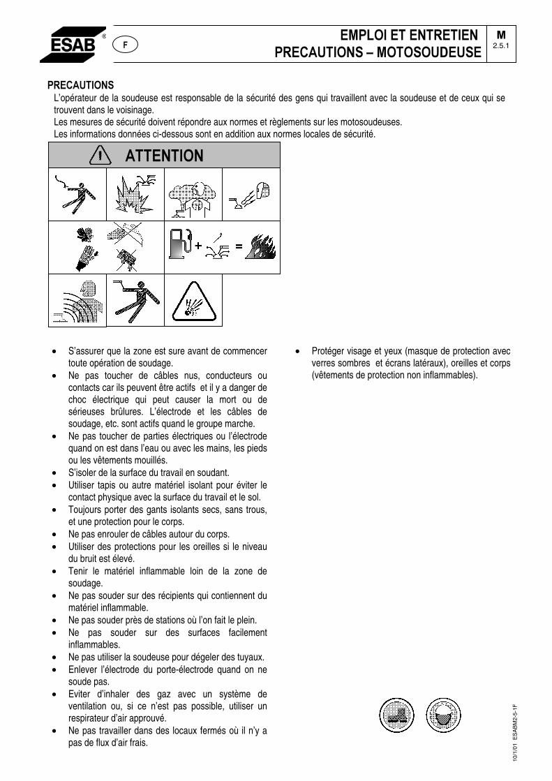
0������1���L’opérateur de la soudeuse est responsable de la sécurité des gens qui travaillent avec la soudeuse et de ceux qui se trouvent dans le voisinage. Les mesures de sécurité doivent répondre aux normes et règlements sur les motosoudeuses. Les informations données ci-dessous sont en addition aux normes locales de sécurité.
• S’assurer que la zone est sure avant de commencer toute opération de soudage.
• Ne pas toucher de câbles nus, conducteurs ou contacts car ils peuvent être actifs et il y a danger de choc électrique qui peut causer la mort ou de sérieuses brûlures. L’électrode et les câbles de soudage, etc. sont actifs quand le groupe marche.
• Ne pas toucher de parties électriques ou l’électrode quand on est dans l’eau ou avec les mains, les pieds ou les vêtements mouillés.
• S’isoler de la surface du travail en soudant. • Utiliser tapis ou autre matériel isolant pour éviter le
contact physique avec la surface du travail et le sol. • Toujours porter des gants isolants secs, sans trous,
et une protection pour le corps. • Ne pas enrouler de câbles autour du corps. • Utiliser des protections pour les oreilles si le niveau
du bruit est élevé. • Tenir le matériel inflammable loin de la zone de
soudage.• Ne pas souder sur des récipients qui contiennent du
matériel inflammable. • Ne pas souder près de stations où l’on fait le plein. • Ne pas souder sur des surfaces facilement
inflammables.• Ne pas utiliser la soudeuse pour dégeler des tuyaux. • Enlever l’électrode du porte-électrode quand on ne
soude pas. • Eviter d’inhaler des gaz avec un système de
ventilation ou, si ce n’est pas possible, utiliser un respirateur d’air approuvé.
• Ne pas travailler dans des locaux fermés où il n’y a pas de flux d’air frais.
• Protéger visage et yeux (masque de protection avec verres sombres et écrans latéraux), oreilles et corps (vêtements de protection non inflammables).
� 0�1���������������0�������1�����1�1�1������
�2.5.1
�������1�
10/1
/01
ES
AB
M2-
5-1F
�
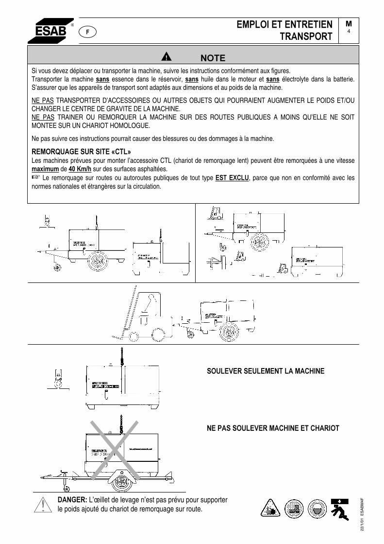
�����������������
�1���2��������/�������/�������
����0����1���2���/���������������1��
������7�L’œillet de levage n’est pas prévu pour supporter le poids ajouté du chariot de remorquage sur route.
�/0�1��������������������01���
��4
Si vous devez déplacer ou transporter la machine, suivre les instructions conformément aux figures. Transporter la machine �� essence dans le réservoir, �� huile dans le moteur et �� électrolyte dans la batterie.S’assurer que les appareils de transport sont adaptés aux dimensions et au poids de la machine.
NE PAS TRANSPORTER D’ACCESSOIRES OU AUTRES OBJETS QUI POURRAIENT AUGMENTER LE POIDS ET/OU CHANGER LE CENTRE DE GRAVITE DE LA MACHINE. NE PAS TRAINER OU REMORQUER LA MACHINE SUR DES ROUTES PUBLIQUES A MOINS QU’ELLE NE SOIT MONTEE SUR UN CHARIOT HOMOLOGUE.
Ne pas suivre ces instructions pourrait causer des blessures ou des dommages à la machine.
��/1�8��������������9���:�Les machines prévues pour monter l’accessoire CTL (chariot de remorquage lent) peuvent être remorquées à une vitesse ��;���� de <=���>� sur des surfaces asphaltées.☞ Le remorquage sur routes ou autoroutes publiques de tout type �����?���, parce que non en conformité avec les normes nationales et étrangères sur la circulation.
22/1
/01
ES
AB
M4F
�
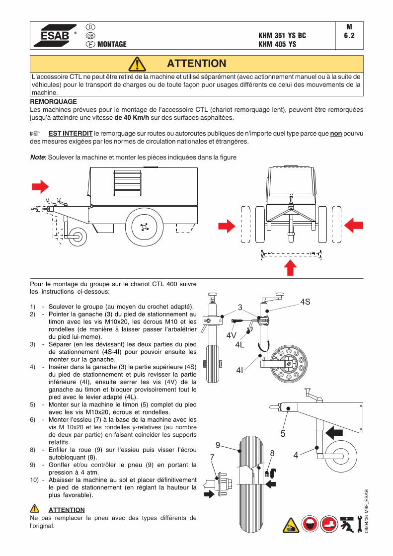
Note: Soulever la machine et monter les pièces indiquées dans la figure
Pour le montage du groupe sur le chariot CTL 400 suivreles instructions ci-dessous:
1) - Soulever le groupe (au moyen du crochet adapté).2) - Pointer la ganache (3) du pied de stationnement au
timon avec les vis M10x20, les écrous M10 et lesrondelles (de manière à laisser passer l’arbalétrierdu pied lui-meme).
3) - Séparer (en les dévissant) les deux parties du piedde stationnement (4S-4I) pour pouvoir ensuite lesmonter sur la ganache.
4) - Insérer dans la ganache (3) la partie supérieure (4S)du pied de stationnement et puis revisser la partieinférieure (4I), ensuite serrer les vis (4V) de laganache au timon et bloquer provisoirement tout lepied avec le levier adapté (4L).
5) - Monter sur la machine le timon (5) complet du piedavec les vis M10x20, écrous et rondelles.
6) - Monter l’essieu (7) à la base de la machine avec lesvis M 10x20 et les rondelles y-relatives (au nombrede deux par partie) en faisant coincider les supportsrelatifs.
8) - Enfiler la roue (9) sur l’essieu puis visser l’écrouautobloquant (8).
9) - Gonfler et/ou contrôler le pneu (9) en portant lapression à 4 atm.
10) - Abaisser la machine au sol et placer définitivementle pied de stationnement (en réglant la hauteur laplus favorable).
ATTENTIONNe pas remplacer le pneu avec des types différents del'original.
ATTENTION
4
5
34S
4I
4L
4V
78
9
REMORQUAGELes machines prévues pour le montage de l’accessoire CTL (chariot remorquage lent), peuvent être remorquéesjusqu’à atteindre une vitesse de 40 Km/h sur des surfaces asphaltées.
☞ EST INTERDIT le remorquage sur routes ou autoroutes publiques de n’importe quel type parce que non pourvudes mesures exigées par les normes de circulation nationales et étrangères.
L’accessoire CTL ne peut être retiré de la machine et utilisé séparément (avec actionnement manuel ou à la suite devéhicules) pour le transport de charges ou de toute façon puor usages différents de celui des mouvements de lamachine.
MONTAGE
M6.2KHM 351 YS BC
KHM 405 YS
06/0
4/06
M6F
_ES
AB
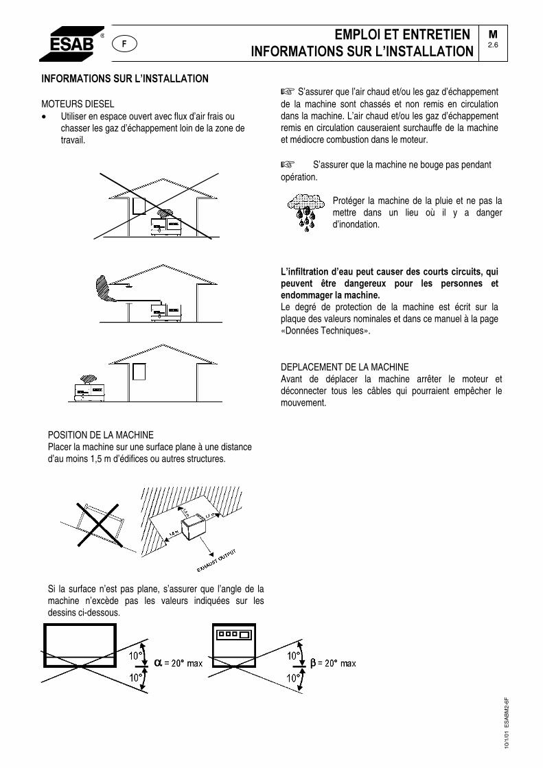
���1�/���1�������������������1��
MOTEURS DIESEL • Utiliser en espace ouvert avec flux d’air frais ou
chasser les gaz d’échappement loin de la zone de travail.
POSITION DE LA MACHINE Placer la machine sur une surface plane à une distance d’au moins 1,5 m d’édifices ou autres structures.
Si la surface n’est pas plane, s’assurer que l’angle de la machine n’excède pas les valeurs indiquées sur les dessins ci-dessous.
� S’assurer que l’air chaud et/ou les gaz d’échappement de la machine sont chassés et non remis en circulation dans la machine. L’air chaud et/ou les gaz d’échappement remis en circulation causeraient surchauffe de la machine et médiocre combustion dans le moteur.
� S’assurer que la machine ne bouge pas pendant opération.
Protéger la machine de la pluie et ne pas la mettre dans un lieu où il y a danger d’inondation.�
����������������������������� ����� ������ �������� �� ������!���� @���� ���"����;� ����� �� � ��� ���� � ����������"�������������#�Le degré de protection de la machine est écrit sur la plaque des valeurs nominales et dans ce manuel à la page «Données Techniques».
DEPLACEMENT DE LA MACHINE Avant de déplacer la machine arrêter le moteur et déconnecter tous les câbles qui pourraient empêcher le mouvement.
�
$/%�1��$��$���$��$�����1�/���1�������������������1��
�2.6
10/1
/01
ES
AB
M2-
6F
��

InstallazioneInstallationInstallation
KHM 405 YSM
2.7
KHM 405 YS
30/0
1/08
794
12-G
B
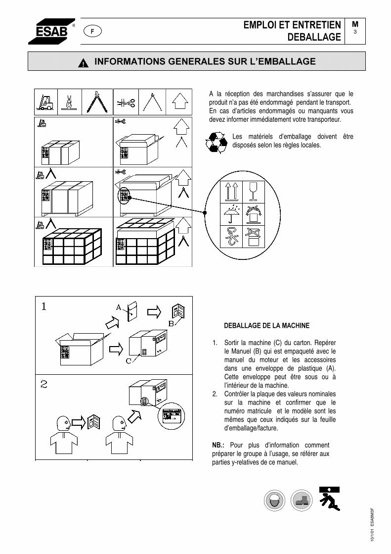
�������������� �������� � ������������
���������������������
1. Sortir la machine (C) du carton. Repérer le Manuel (B) qui est empaqueté avec le manuel du moteur et les accessoires dans une enveloppe de plastique (A). Cette enveloppe peut être sous ou à l’intérieur de la machine.
2. Contrôler la plaque des valeurs nominales sur la machine et confirmer que le numéro matricule et le modèle sont les mêmes que ceux indiqués sur la feuille d’emballage/facture.
�� , Pour plus d’information comment préparer le groupe à l’usage, se référer aux parties y-relatives de ce manuel.
��� �
10/1
/01
ES
AB
M3F
A la réception des marchandises s’assurer que le produit n’a pas été endommagé pendant le transport. En cas d’articles endommagés ou manquants vous devez informer immédiatement votre transporteur.
Les matériels d’emballage doivent être disposés selon les règles locales.
������������������������������
��3��
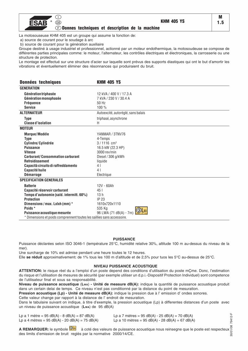
KHM 405 YSM
1.5Donnes techniques et description de la machine
La motosouseuse KHM 405 est un groupe qui assume la fonction de: a) source de courant pour le soudage à arc b) source de courant pour la génération auxiliaireGroupe destiné à usage industriel et professionnel, actionné par un moteur endothermique, la motosoudeuse se compose dedifférentes parties principales comme: le moteur, l’alternateur, les contrôles électriques et électroniques, la carrosserie ou unestructure de protection.Le montage est effectué sur une structure d’acier sur laquelle sont prévus des supports élastiques qui ont le but d’amortir lesvibrations et éventuellement éliminer des résonnances qui produiraient du bruit.
Données techniques KHM 405 YSGENERATION
Génération triphasée 12 kVA / 400 V / 17.3 AGénération monophasée 7 kVA / 230 V / 30.4 AFréquence 50 HzService 100 %
ALTERNATEUR Autoexcité, autoréglé, sans balaisType triphasé, asynchroneClasse d’isolation H
MOTEURMarque/ Modéle YANMAR / 3TNV76
Type 4-TempsCylindre/ Cylindrée 3 / 1116 cm3
Puissance 16.5 kW (22.3 HP)Vitesse 3000 rev/minCarburant/ Consommation carburant Diesel / 306 g/kWhRefroidissement liquideCapacità circuito di raffreddamento 4 lCapacité huile 4 lDémarrage Electrique
SPECIFICATION GENERALESBatterie 12V - 60AhCapacité réservoir carburant 45 lTemps d’autonomie (sald. intermitt. 60%) 13 hProtection IP 23Dimensions / max. Lxlxh (mm) * 1610x720x1110Poids * 535 KgPuissance acoustique mesurée 96 LWA (71 dB(A) - 7m)* Dimensions et poids comprennent toutes les saillies sans accessoire.
30/0
1/08
794
12-F
PUISSANCEPuissance déclarées selon ISO 3046-1 (température 25°C, humidité relative 30%, altitude 100 m au-dessus du niveau de lamer).Une surcharge de 10% est admise pendant une heure toutes le 12 heures.Elle se réduit approximativement: de 1% tous les 100 m d’altitude et de 2,5% pour tuos les 5°C au-dessus de 25°C.
NIVEAU PUISSANCE ACOUSTIQUEATTENTION: le risque rèel du a l’emploi d’un poste depend des conditions d’utilisation du poste mÇme. Donc, l’estimationdu risque et l’utilisation de mesures de sécurité (par exemple utiliser un d.p.i.-Dispositif Protection Individuel) sont competencede l’utilisateur final et sous sa responsabilité.Niveau de puissance acoustique (LWA) - Unité de measure dB(A): indique la quantitè de puissance acoustique produitdans un certain delai de temps. Ce niveau n’est pas conditionné par la distance du point de mesuration.Pression acoustique (Lp) - Unité de measure dB(A): indique la pression due à l’ emission d’ ondes sonores.Cette valeur change par rapport à la distance de l’ endroit de mesuration.Dans le tabulaire suivant on indique, à titre d’exemple, la pression acoustique (Lp) à differentes distances d’un poste avecun niveau de puissance acoustique (LWA) de 95 dB(A)
Lp a 1 mètre = 95 dB(A) - 8 dB(A) = 87 dB(A) Lp a 7 mètres = 95 dB(A) - 25 dB(A) = 70 dB(A)Lp a 4 mètres = 95 dB(A) - 20 dB(A) = 75 dB(A) Lp a 10 mètres = 95 dB(A) - 28 dB(A) = 67 dB(A)
A REMARQUER: le symbole à coté des valeurs de puissance acoustique nous reinsegne que le poste est respecteuxdes limits d’emission de bruit reglés par la normative 2000/14/CE.
2000 / 14 / CE
2000 / 14 / CE
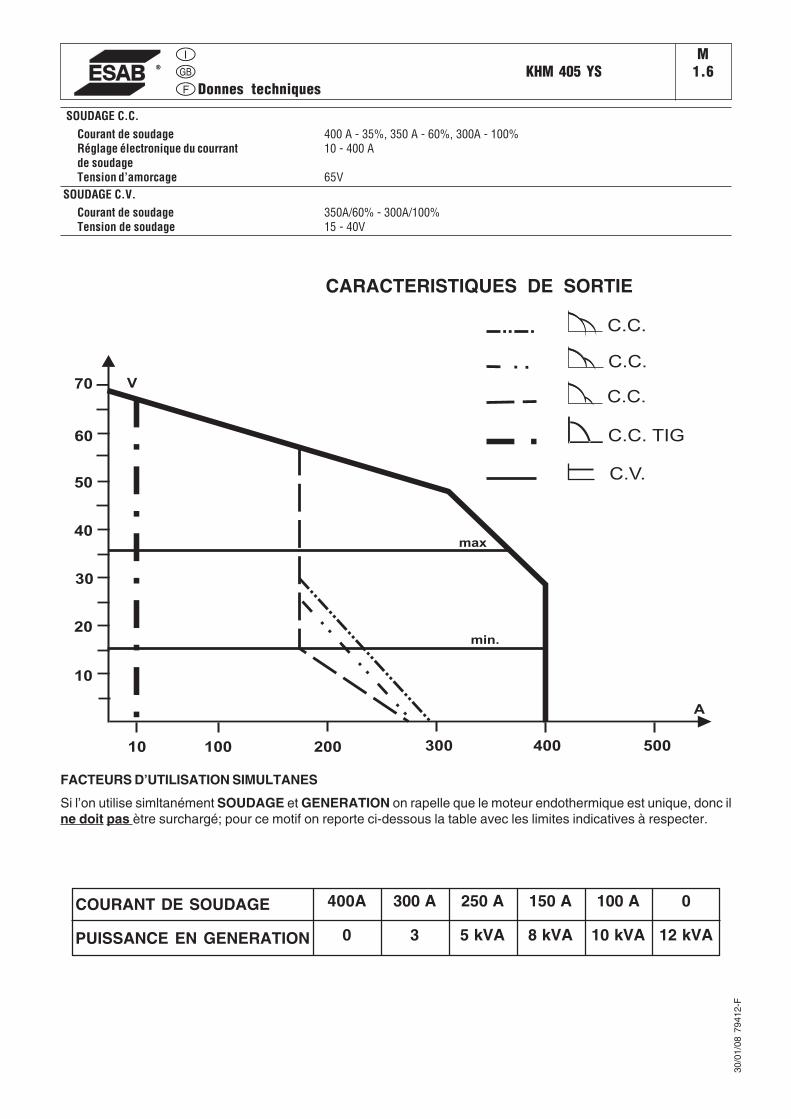
KHM 405 YSM
1.6Donnes techniques
SOUDAGE C.C.Courant de soudage 400 A - 35%, 350 A - 60%, 300A - 100%Réglage électronique du courrant 10 - 400 Ade soudageTension d’amorcage 65V
SOUDAGE C.V.Courant de soudage 350A/60% - 300A/100%Tension de soudage 15 - 40V
30/0
1/08
794
12-F
FACTEURS D’UTILISATION SIMULTANES
Si l’on utilise simltanément SOUDAGE et GENERATION on rapelle que le moteur endothermique est unique, donc ilne doit pas ètre surchargé; pour ce motif on reporte ci-dessous la table avec les limites indicatives à respecter.
8 kVA5 kVA30PUISSANCE EN GENERATION
250 A300 A400ACOURANT DE SOUDAGE 0150 A 100 A
10 kVA 12 kVA
100 200 300 400 500
A
V
10
20
30
40
50
60
70
10
min.
max
C.V.
C.C. TIG
C.C.
C.C.
C.C.
CARACTERISTIQUES DE SORTIE
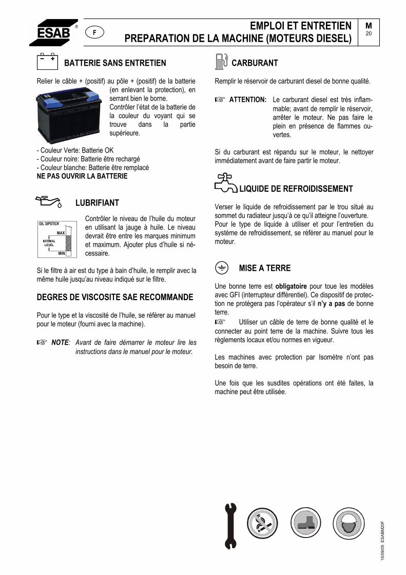
EMPLOI ET ENTRETIENPREPARATION DE LA MACHINE (MOTEURS DIESEL)
BATTERIE SANS ENTRETIEN
M20F
Relier le câble + (positif) au pôle + (positif) de la batterie (en enlevant la protection), en serrant bien le borne. Contrôler l’état de la batterie de la couleur du voyant qui se trouve dans la partie supérieure.
- Couleur Verte: Batterie OK- Couleur noire: Batterie être rechargé- Couleur blanche: Batterie être remplacé NE PAS OUVRIR LA BATTERIE
LUBRIFIANTContrôler le niveau de l’huile du moteur en utilisant la jauge à huile. Le niveau devrait être entre les marques minimum et maximum. Ajouter plus d’huile si né-cessaire.
Si le filtre à air est du type à bain d’huile, le remplir avec la même huile jusqu’au niveau indiqué sur le filtre.
DEGRES DE VISCOSITE SAE RECOMMANDE
Pour le type et la viscosité de l’huile, se référer au manuel pour le moteur (fourni avec la machine).
NOTE: Avant de faire démarrer le moteur lire les instructions dans le manuel pour le moteur.
CARBURANT
Remplir le réservoir de carburant diesel de bonne qualité.
ATTENTION: Le carburant diesel est très inflam-mable; avant de remplir le réservoir, arrêter le moteur. Ne pas faire le plein en présence de flammes ou-vertes.
Si du carburant est répandu sur le moteur, le nettoyer immédiatement avant de faire partir le moteur.
LIQUIDE DE REFROIDISSEMENT
Verser le liquide de refroidissement par le trou situé au sommet du radiateur jusqu’à ce qu’il atteigne l’ouverture. Pour le type de liquide à utiliser et pour l’entretien du système de refroidissement, se référer au manuel pour le moteur.
MAX
MIN
MISE A TERRE
Une bonne terre est obligatoire pour toue les modèles avec GFI (interrupteur différentiel). Ce dispositif de protec-tion ne protègera pas l’opérateur s’il n’y a pas de bonne terre.
Utiliser un câble de terre de bonne qualité et le connecter au point terre de la machine. Suivre tous les règlements locaux et/ou normes en vigueur.
Les machines avec protection par Isomètre n’ont pas besoin de terre.
Une fois que les susdites opérations ont été faites, la machine peut être utilisée.
15/0
9/05
ES
AB
M20
F
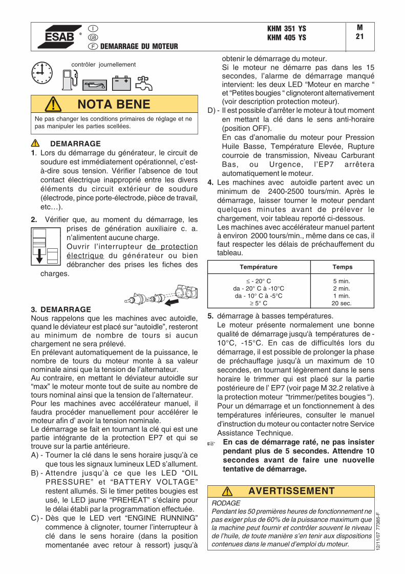
DEMARRAGE DU MOTEUR
KHM 351 YSKHM 405 YS
M21
12/1
1/07
773
85-F
Ne pas changer les conditions primaires de réglage et nepas manipuler les parties scellées.
NOTA BENE
DEMARRAGE1. Lors du démarrage du générateur, le circuit de
soudure est immédiatement opérationnel, c’est-à-dire sous tension. Vérifier l’absence de toutcontact électrique inapproprié entre les diverséléments du circuit extérieur de soudure(électrode, pince porte-électrode, pièce de travail,etc…).
2. Vérifier que, au moment du démarrage, lesprises de génération auxiliaire c. a.n’alimentent aucune charge.Ouvrir l’interrupteur de protectionélectrique du générateur ou biendébrancher des prises les fiches des
charges.
3. DEMARRAGENous rappelons que les machines avec autoidle,quand le déviateur est placé sur “autoidle”, resterontau minimum de nombre de tours si aucunchargement ne sera prélevé.En prélevant automatiquement de la puissance, lenombre de tours du moteur monte à sa valeurnominale ainsi que la tension de l’alternateur.Au contraire, en mettant le déviateur autoidle sur“max” le moteur monte tout de suite au nombre detours nominal ainsi que la tension de l’alternateur.Pour les machines avec accélérateur manuel, ilfaudra procéder manuellement pour accélérer lemoteur afin d’ avoir la tension nominale.Le démarrage se fait en tournant la clé qui est unepartie intégrante de la protection EP7 et qui setrouve sur la partie antérieure.A) - Tourner la clé dans le sens horaire jusqu’à ce
que tous les signaux lumineux LED s’allument.B) - Attendre jusqu’à ce que les LED “OIL
PRESSURE” et “BATTERY VOLTAGE”restent allumés. Si le timer petites bougies estusé, le LED jaune “PREHEAT” s’éclaire pourle délai établi par la programmation effectuée.
C) - Dès que le LED vert “ENGINE RUNNING”commence à clignoter, tourner l’interrupteur àclé dans le sens horaire (dans la positionmomentanée avec retour à ressort) jusqu’à
Température Temps
≤ - 20° Cda - 20° C à -10°Cda - 10° C à -5°C
≥ 5° C
5 min.2 min.1 min.20 sec.
RODAGEPendant les 50 premières heures de fonctionnement nepas exiger plus de 60% de la puissance maximum quela machine peut fournir et contrôler souvent le niveaude l’huile, de toute manière s’en tenir aux dispositionscontenues dans le manuel d’emploi du moteur.
AVERTISSEMENT
contrôler journellementobtenir le démarrage du moteur.Si le moteur ne démarre pas dans les 15secondes, l’alarme de démarrage manquéintervient: les deux LED “Moteur en marche “et “Petites bougies “ clignoteront alternativement(voir description protection moteur).
D) - Il est possible d’arrêter le moteur à tout momenten mettant la clé dans le sens anti-horaire(position OFF).En cas d’anomalie du moteur pour PressionHuile Basse, Température Elevée, Rupturecourroie de transmission, Niveau CarburantBas, ou Urgence, l’EP7 arrêteraautomatiquement le moteur.
4. Les machines avec autoidle partent avec unminimum de 2400-2500 tours/min. Après ledémarrage, laisser tourner le moteur pendantquelques minutes avant de prélever lechargement, voir tableau reporté ci-dessous.Les machines avec accélérateur manuel partentà environ 2000 tours/min., même dans ce cas, ilfaut respecter les délais de préchauffement dutableau.
5. démarrage à basses températures.Le moteur présente normalement une bonnequalité de démarrage jusqu'à températures de -10°C, -15°C. En cas de difficultés lors dudémarrage, il est possible de prolonger la phasede préchauffage jusqu’à un maximum de 10secondes, en tournant légèrement dans le senshoraire le trimmer qui est placé sur la partiepostérieure de l’ EP7 (voir page M 32.2 relative àla protection moteur “trimmer/petites bougies “).Pour un démarrage et un fonctionnement à destempératures inférieures, consulter le manueld’instruction du moteur ou contacter notre ServiceAssistance Technique.
En cas de démarrage raté, ne pas insisterpendant plus de 5 secondes. Attendre 10secondes avant de faire une nuovelletentative de démarrage.
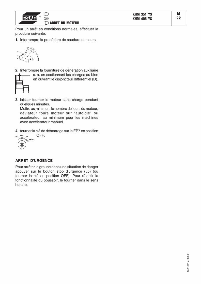
ARRET DU MOTEUR
KHM 351 YSKHM 405 YS
M22
12/1
1/07
773
85-F
Pour un arrêt en conditions normales, effectuer laprocdure suivante:
1. Interrompre la procédure de soudure en cours.
OFFON
START
2. Interrompre la fourniture de génération auxiliairec. a. en sectionnant les charges ou bienen ouvrant le disjoncteur différentiel (D).
3. laisser tourner le moteur sans charge pendantquelques minutes.Mettre au minimum le nombre de tours du moteur,déviateur tours moteur sur “autoidle” ouaccélérateur au minimum pour les machinesavec accélérateur manuel.
4. tourner la clé de démarrage sur le EP7 en positionOFF.
ARRET D'URGENCE
Pour arrêter le groupe dans une situation de dangerappuyer sur le bouton stop d'urgence (L5) (outourner la clé en position OFF). Pour rétablir lafonctionnalité du poussoir, le tourner dans le senshoraire.

30/0
1/08
794
12-G
B
ComandiControlsCommandes
KHM 405 YSM31
Pos. Descrizione Description Description91015
59A59B59CC2D
H8I3I8L5NMO8
Q7T
V4X1
Presa di saldatura (+)Presa di saldatura (-)Presa di corrente in c.a.Protezione termica motoreProtezione termica corrente auxProtezione termica alim.trainafilo 42VIndicatore livello combustibileInterruttore differenziale (30mA)Unità controllo motore EP7Commut. riduz. scala saldaturaSelettore AUTOIDLEPulsante stop emergenzaVoltmetroContaoreScheda strum. V/A digitalie scheda LED V.R.D.Selettore modalità saldaturaRegolatore corrente di saldaturaComando invertitore polaritàPresa per comando a distanza
Welding socket ( + )Welding socket ( - )A.C. socketEngine thermal switchAux current thermal switchSupply therm.switch wire feeder 42V
Fuel level lightG.F.I.Engine control unit EP7Welding scale switchAUTOIDLE switchEmergency buttonVoltmeteHour counterV/A digital instruments PCBand Led V.R.D. PCBWelding selector modeWelding current regulatorPolarity inverter controlRemote control socket
Prise de soudage ( + )Prise de soudage ( - )Prises de courant en c.a.Protection thermique moteurProtection thermique courant aux.Protection thermique alimentation 42V filIndicateur niveau carburantlnterrupteur différentielProtection moteur EP7Commutateur échelle soudageSelecteur AUTOIDLEBouton d’urgenceVoltmètreCompte-heuresPlatine Volt/Amp.-mètre digitaleet platine LED V.R.D.Sélecteur modalité soudageRégulateur courant soudageCommande inverseur polaritéPrise pour télécommande
ReferenzlisteSchweißbuchse (+)Schweißbuchse (-)Steckdose ACThermoschutz MotorThermoschutz HilfsstromThermoschutz DrahtvorschubAnzeige KraftstoffpegelFI-Schalter (GFI)Motorschutz EP7Bereichsschalter SchweißstromWahlschalter DrehzahlverstellungNotschalterVoltmeterStundenzählerPlatine-Digitale Anzeige Volt /Ampereund platine-Anzeige V.R.D.SchveißschalterSchweißstromreglerPolwendeschalterSteckdose Fernbedienung
15
910
12
L5
I8
59A
59B
H8C2DN
Q7
T
X1
I3
M
59CV4
(PL Version)
O8
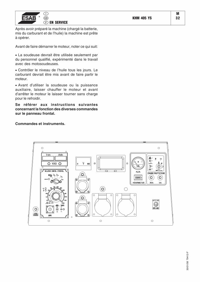
EN SERVICEKHM 405 YS
M32
30/0
1/08
794
12-F
Après avoir préparé la machine (chargé la batterie,mis du carburant et de l’huile) la machine est prêteà opérer.
Avant de faire démarrer le moteur, noter ce qui suit:
• La soudeuse devrait être utilisée seulement pardu personnel qualifié, expérimenté dans le travailavec des motosoudeuses.
• Contrôler le niveau de l’huile tous les jours. Lecarburant devrait être mis avant de faire partir lemoteur.
• Avant d’utiliser la soudeuse ou la puissanceauxiliaire, laisser chauffer le moteur et avantd’arrêter le moteur le laisser tourner sans chargepour le refroidir.
Se référer aux instructions suivantesconcernant la fonction des diverses commandessur le panneau frontal.
Commandes et instruments.
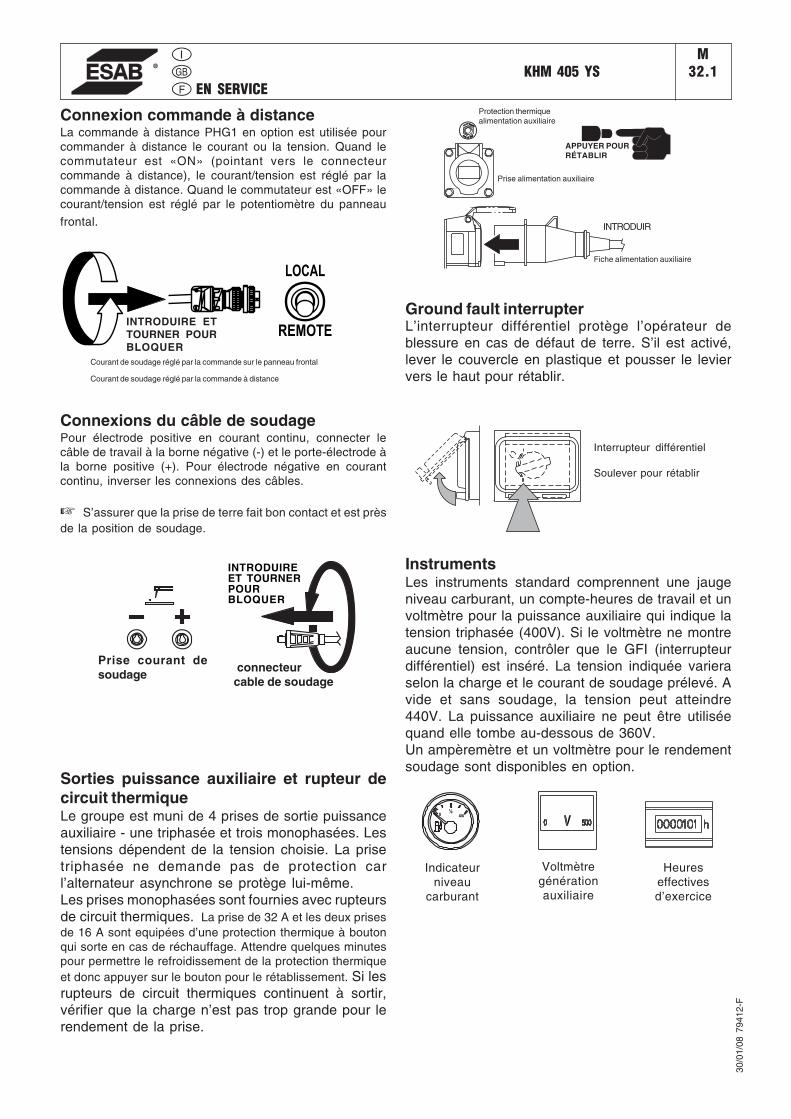
EN SERVICEKHM 405 YS
M32.1
Connexion commande à distanceLa commande à distance PHG1 en option est utilisée pourcommander à distance le courant ou la tension. Quand lecommutateur est «ON» (pointant vers le connecteurcommande à distance), le courant/tension est réglé par lacommande à distance. Quand le commutateur est «OFF» lecourant/tension est réglé par le potentiomètre du panneau
frontal.
Connexions du câble de soudagePour électrode positive en courant continu, connecter lecâble de travail à la borne négative (-) et le porte-électrode àla borne positive (+). Pour électrode négative en courantcontinu, inverser les connexions des câbles.
☞ S’assurer que la prise de terre fait bon contact et est prèsde la position de soudage.
30/0
1/08
794
12-F
Ground fault interrupterL’interrupteur différentiel protège l’opérateur deblessure en cas de défaut de terre. S’il est activé,lever le couvercle en plastique et pousser le leviervers le haut pour rétablir.
InstrumentsLes instruments standard comprennent une jaugeniveau carburant, un compte-heures de travail et unvoltmètre pour la puissance auxiliaire qui indique latension triphasée (400V). Si le voltmètre ne montreaucune tension, contrôler que le GFI (interrupteurdifférentiel) est inséré. La tension indiquée varieraselon la charge et le courant de soudage prélevé. Avide et sans soudage, la tension peut atteindre440V. La puissance auxiliaire ne peut être utiliséequand elle tombe au-dessous de 360V.Un ampèremètre et un voltmètre pour le rendementsoudage sont disponibles en option.
Sorties puissance auxiliaire et rupteur decircuit thermiqueLe groupe est muni de 4 prises de sortie puissanceauxiliaire - une triphasée et trois monophasées. Lestensions dépendent de la tension choisie. La prisetriphasée ne demande pas de protection carl’alternateur asynchrone se protège lui-même.Les prises monophasées sont fournies avec rupteursde circuit thermiques. La prise de 32 A et les deux prisesde 16 A sont equipées d’une protection thermique à boutonqui sorte en cas de réchauffage. Attendre quelques minutespour permettre le refroidissement de la protection thermiqueet donc appuyer sur le bouton pour le rétablissement. Si lesrupteurs de circuit thermiques continuent à sortir,vérifier que la charge n’est pas trop grande pour lerendement de la prise.
INTRODUIRE ETTOURNER POURBLOQUER
Courant de soudage réglé par la commande sur le panneau frontal
Courant de soudage réglé par la commande à distance
LOCAL
REMOTE
INTRODUIREET TOURNERPOURBLOQUER
connecteurcable de soudage
Prise courant desoudage
TO
PRESS RESET
CIRCUIT BREAKER
TO
PRESS RESET
CIRCUIT BREAKER
APPUYER POURRÉTABLIR
Protection thermiquealimentation auxiliaire
Prise alimentation auxiliaire
INTRODUIR
4/4
½0
Indicateurniveau
carburant
Fiche alimentation auxiliaire
Interrupteur différentiel
Soulever pour rétablir
Heureseffectivesd’exercice
Voltmètregénérationauxiliaire
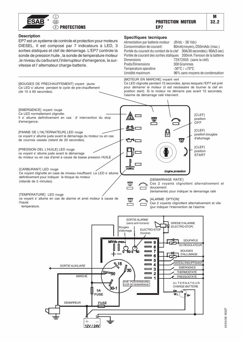
PROTECTIONSPROTECTION MOTEUREP7
M32.2
24/0
4/08
M32
F
DescriptionEP7 est un systeme de controle et protection pour moteursDIESEL. Il est composé par 7 indicateurs à LED, 3sorties statiques et clef de démarrage. L'EP7 controle lasonde de pression huile , la sonde de temperature moteur,le niveau du carburant,l'interrupteur d'emergence, la sur-vitesse et l' alternateur charge-batterie.
[BOUGIES DE PRECHAUFFEMENT] voyant jauneCe LED s' allume pendant le cycle de pre-chauffement(de 10 à 60 secondes).
[PANNE DE L?ALTERNATEUR] LED rougece voyant s' allume juste avant le démarrage du moteur ou en casde courroie cassée (retard de 20 secondes).
[PRESSION DEL L'HUILE] LED rougece voyant s' allume juste avant le démarragedu moteur ou en cas d'arret à cause de basse pression HUILE .
[CARBURANT] LED rougeCe voyant clignotte en case de miveau insuffisant. Le LED s' allumedefinitivement pour indiquer le bloque du moteur(retardé de 5 minutes).
[TEMPERATURE] LED rougece voyant s' allume en cas de alarme et arret moteur à cause del'haute temperature.
[MOTEUR EN MARCHE] voyant vertCe LED clignotte pendant 15 secondes, àpres lesquels l'EP7 est prètpour démarrer le moteur (il est necessaire de tourner la clef enposition start). Si le moteur ne démarre pas avant 15 secondes,l'alarme de démarrage raté intervient.
[CLEF]positionOFF
[EMERGENCE] voyant rougeCe LED normallement clignotte.Il s' allume definitivement en cas d' intervention du stopd'emergence.
Specifiques tecniquesAlimentation par batterie moteur (8Vdc - 36 Vdc)Consommation de courant: 80mA(moyen),/250mAdc (max.)Portée du courant du contact de la clef 30A(30 secondes) / 80A(5 sec)Portée de courant des sorties statiques 200mA /Tension de la batterieDimensions 72X72X55 (sans la clef)Poids/Dimensions 300 GrammesTemperature operative -30°C / +70°CUmidité maximum 96% sans moyens de condensation
[CLEF]position bougiesd'allumage
[CLEF]positionSTART
[DEMARRAGE RATE']Ces 2 voyants clignottent alternativement etdoucement(lentamente) pour indiquer le demarrage raté
[ALARME OPTION]Ces 2 voyants clignottent alternativement et vite(pur indiquer l'intervention de l'alarme
5AFUSE
FUSE
Bougiesd'allumage
VUE POSTERIEURECLEF DE DEMARRAGE
ELECTRO-STOP(horaire)
SOUPAPLE
OU REGOLATEUR
SIRENE D'ALARME(ELECTRO-STOP)
BOUGIESD'ALLUMAGE
NIVEAU INSUFFISANT
EMERGENCE
THERMOSTATE
PRESSOSTATE
SORTIE ALARME(sens anti-horaire)
A L T E R N A T E U RCHARGE-BATTERIE
SORTIE AUXILIARE
MARCHE
DEMARREUR
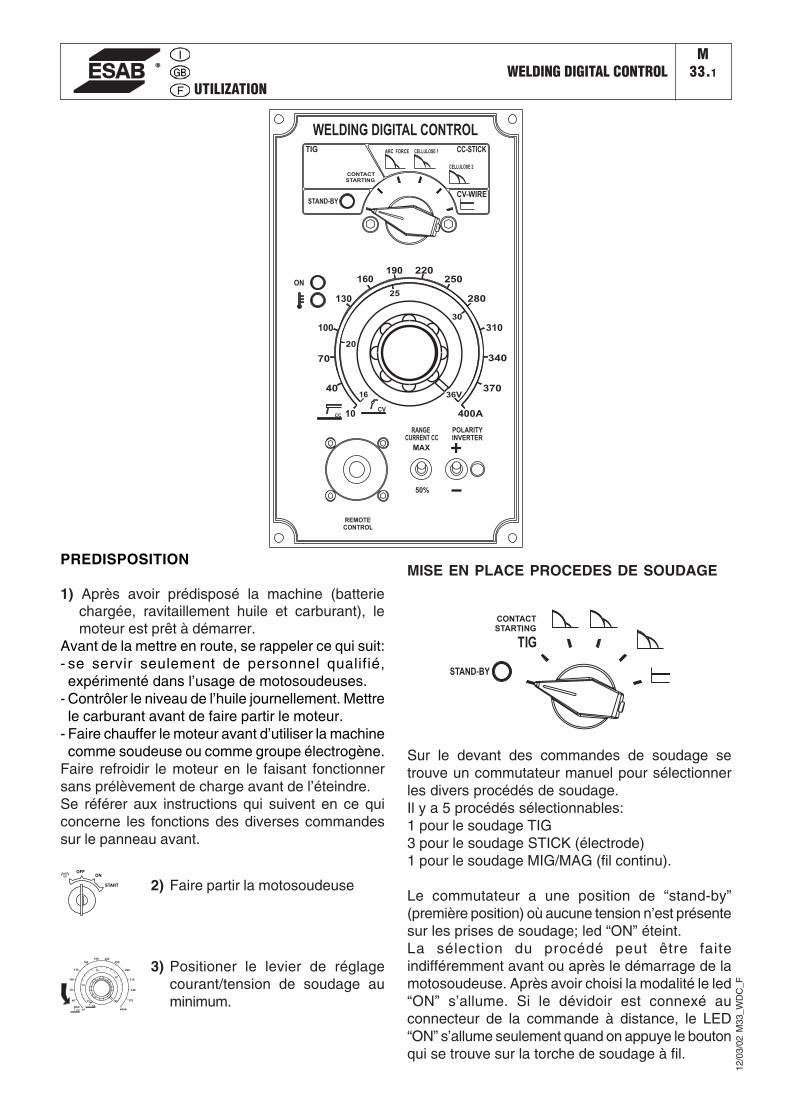
UTILIZATIONWELDING DIGITAL CONTROL
M33.1
12/0
3/02
M33
_WD
C_F
PREDISPOSITION
1) Après avoir prédisposé la machine (batteriechargée, ravitaillement huile et carburant), lemoteur est prêt à démarrer.
Avant de la mettre en route, se rappeler ce qui suit:- se servir seulement de personnel qualifié,expérimenté dans l’usage de motosoudeuses.
- Contrôler le niveau de l’huile journellement. Mettrele carburant avant de faire partir le moteur.
- Faire chauffer le moteur avant d’utiliser la machinecomme soudeuse ou comme groupe électrogène.
Faire refroidir le moteur en le faisant fonctionnersans prélèvement de charge avant de l’éteindre.Se référer aux instructions qui suivent en ce quiconcerne les fonctions des diverses commandessur le panneau avant.
2) Faire partir la motosoudeuseOFF
ON
START
3) Positioner le levier de réglagecourant/tension de soudage auminimum.
MISE EN PLACE PROCEDES DE SOUDAGE
CVCC
STAND-BY
CONTACT
STARTING
REMOTE
CONTROL
70
20
25
40
100
WELDING DIGITAL CONTROL
130
160190 220
250
280
310
340
370
400A
36V16
10
30
ON
POLARITY
CURRENT CC
MAX
50%
INVERTER
RANGE
TIG ARC FORCE CELLULOSE 1
CELLULOSE 2
CC-STICK
CV-WIRE
Sur le devant des commandes de soudage setrouve un commutateur manuel pour sélectionnerles divers procédés de soudage.Il y a 5 procédés sélectionnables:1 pour le soudage TIG3 pour le soudage STICK (électrode)1 pour le soudage MIG/MAG (fil continu).
Le commutateur a une position de “stand-by”(première position) où aucune tension n’est présentesur les prises de soudage; led “ON” éteint.La sélection du procédé peut être faiteindifféremment avant ou après le démarrage de lamotosoudeuse. Après avoir choisi la modalité le led“ON” s’allume. Si le dévidoir est connexé auconnecteur de la commande à distance, le LED“ON” s’allume seulement quand on appuye le boutonqui se trouve sur la torche de soudage à fil.
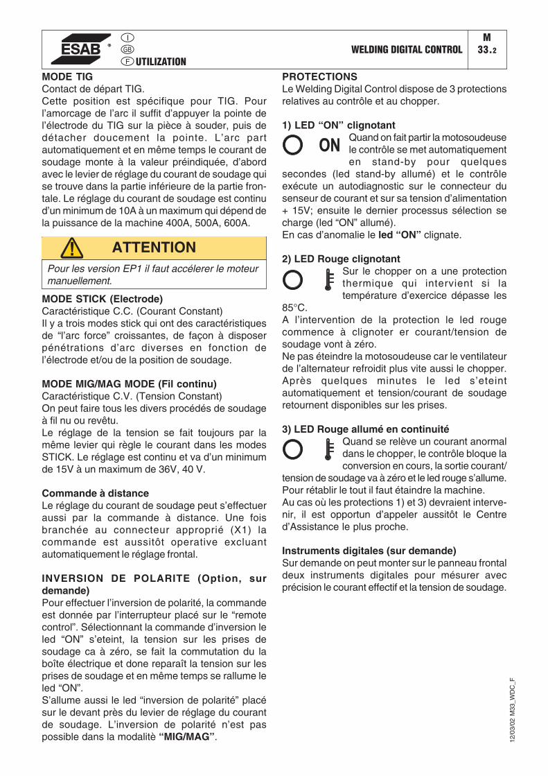
UTILIZATIONWELDING DIGITAL CONTROL
M33.2
12/0
3/02
M33
_WD
C_F
MODE TIGContact de départ TIG.Cette position est spécifique pour TIG. Pourl’amorcage de l’arc il suffit d’appuyer la pointe del’électrode du TIG sur la pièce à souder, puis dedétacher doucement la pointe. L’arc partautomatiquement et en même temps le courant desoudage monte à la valeur préindiquée, d’abordavec le levier de réglage du courant de soudage quise trouve dans la partie inférieure de la partie fron-tale. Le réglage du courant de soudage est continud’un minimum de 10A à un maximum qui dépend dela puissance de la machine 400A, 500A, 600A.
PROTECTIONSLe Welding Digital Control dispose de 3 protectionsrelatives au contrôle et au chopper.
1) LED “ON” clignotantQuand on fait partir la motosoudeusele contrôle se met automatiquementen stand-by pour quelques
secondes (led stand-by allumé) et le contrôleexécute un autodiagnostic sur le connecteur dusenseur de courant et sur sa tension d’alimentation+ 15V; ensuite le dernier processus sélection secharge (led “ON” allumé).En cas d’anomalie le led “ON” clignate.
2) LED Rouge clignotantSur le chopper on a une protectionthermique qui intervient si latempérature d’exercice dépasse les
85°C.A l’intervention de la protection le led rougecommence à clignoter er courant/tension desoudage vont à zéro.Ne pas éteindre la motosoudeuse car le ventilateurde l’alternateur refroidit plus vite aussi le chopper.Après quelques minutes le led s’eteintautomatiquement et tension/courant de soudageretournent disponibles sur les prises.
3) LED Rouge allumé en continuitéQuand se relève un courant anormaldans le chopper, le contrôle bloque laconversion en cours, la sortie courant/
tension de soudage va à zéro et le led rouge s’allume.Pour rétablir le tout il faut étaindre la machine.Au cas où les protections 1) et 3) devraient interve-nir, il est opportun d’appeler aussitôt le Centred’Assistance le plus proche.
Instruments digitales (sur demande)Sur demande on peut monter sur le panneau frontaldeux instruments digitales pour mésurer avecprécision le courant effectif et la tension de soudage.
MODE STICK (Electrode)Caractéristique C.C. (Courant Constant)Il y a trois modes stick qui ont des caractéristiquesde “l’arc force” croissantes, de façon à disposerpénétrations d’arc diverses en fonction del’électrode et/ou de la position de soudage.
MODE MIG/MAG MODE (Fil continu)Caractéristique C.V. (Tension Constant)On peut faire tous les divers procédés de soudageà fil nu ou revêtu.Le réglage de la tension se fait toujours par lamême levier qui règle le courant dans les modesSTICK. Le réglage est continu et va d’un minimumde 15V à un maximum de 36V, 40 V.
Commande à distanceLe réglage du courant de soudage peut s’effectueraussi par la commande à distance. Une foisbranchée au connecteur approprié (X1) lacommande est aussitôt operative excluantautomatiquement le réglage frontal.
INVERSION DE POLARITE (Option, surdemande)Pour effectuer l’inversion de polarité, la commandeest donnée par l’interrupteur placé sur le “remotecontrol”. Sélectionnant la commande d’inversion leled “ON” s’eteint, la tension sur les prises desoudage ca à zéro, se fait la commutation du laboîte électrique et done reparaît la tension sur lesprises de soudage et en même temps se rallume leled “ON”.S’allume aussi le led “inversion de polarité” placésur le devant près du levier de réglage du courantde soudage. L’inversion de polarité n’est paspossible dans la modalitè “MIG/MAG”.
Pour les version EP1 il faut accélerer le moteurmanuellement.
ATTENTION
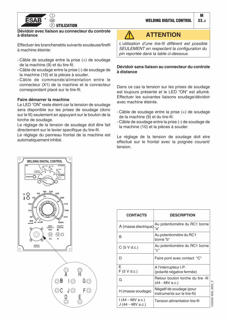
UTILIZATIONWELDING DIGITAL CONTROL
M33.3
12/0
3/02
M33
_WD
C_F
Dévidoir avec liaison au connecteur du controleà distance
Effectuer les branchenebts suivants soudeuse/tirefilà machine éteinte:
- Câble de soudage entre la prise (+) de soudagede la machine (9) et du tire-fil.
- Câble de soudage entre la prise (-) de soudage dela machine (10) et la pièces à souder.
- Câble de commande/alimentation entre leconnecteur (X1) de la machine et le connecteurcorrespondant placé sur le tire-fil.
Faire démarrer la machineLe LED “ON” reste éteint car la tension de soudagesera disponible sur les prises de soudage (doncsur le fil) seulement en appuyant sur le bouton de latorche de soudage.Le réglage de la tension de soudage doit être faitdirectement sur le levier specifique du tire-fil.Le réglage du panneau frontal de la machine estautomatiquement inhibé.
L’utilisation d’une tire-fil différent est possibleSEULEMENT en respectant la configuration dupin reportée dans la table ci-dessous.
ATTENTION
CONTACTS
A (masse électrique)
B
C (5 V d.c.)
D
EF (5 V d.c.)
G
H (masse soudage)
I (44 - 48V a.c.)J (44 - 48V a.c.)
DESCRIPTION
Au potentiomètre du RC1 borne“a”
Au potentiomètre du RC1borne "b"
Au potentiomètre du RC1 borne"c"
Faire pont avec contact "C"
A l’interrupteur I.P.(polarité négative fermée)
Retour bouton torche du tire -fil(44 - 48V a.c.)
Négatif de soudage (pourinstruments sur le tire-fil)
CVCC
STAND-BY
CONTACT
STARTING
REMOTE
CONTROL
70
20
25
40
100
WELDING DIGITAL CONTROL
130
160190 220
250
280
310
340
370
400A
36V16
10
30
ON
POLARITY
CURRENT CC
MAX
50%
INVERTER
RANGE
TIG ARC FORCE CELLULOSE 1
CELLULOSE 2
CC-STICK
CV-WIRE
Dévidoir sans liaison au connecteur du controleà distance
Dans ce cas la tension sur les prises de soudageest toujours présente et le LED “ON” est allumé.Effectuer les suivantes liaisons soudage/dévidoiravec machine éteinte.
- Câble de soudage entre la prise (+) de soudagede la machine (9) et du tire-fil.
- Câble de soudage entre la prise (-) de soudage dela machine (10) et la pièces à souder.
Le réglage de la tension de soudage doit etreeffectué sur le frontal avec la poignée courant/tension.
Tension alimentation tire-fil
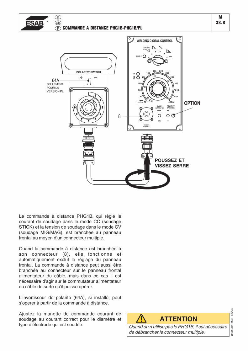
08/0
3/05
M38
_ES
AB
ATTENTION
COMMANDE A DISTANCE PHG1B-PHG1B/PL
M38.8
SEULEMENTPOUR LAVERSION PL
Le commande à distance PHG1B, qui règle lecourant de soudage dans le mode CC (soudageSTICK) et la tension de soudage dans le mode CV(soudage MIG/MAG), est branchée au panneaufrontal au moyen d’un connecteur multiple.
Quand la commande à distance est branchée àson connecteur (8), elle fonctionne etautomatiquement exclut le réglage du panneaufrontal. La commande à distance peut aussi êtrebranchée au connecteur sur le panneau frontalalimentateur du câble, mais dans ce cas il estnécessaire d’agir sur le commutateur alimentateurdu câble de sorte qu’il puisse opérer.
L’invertisseur de polarité (64A), si installé, peuts’operer à partir de la commande à distance.
Ajustez la manette de commande courant desoudage au courant correct pour le diamètre ettype d’électrode qui est soudée. Quand on n’utilise pas le PHG1B, il est nécessaire
de débrancher le connecteur multiple.
POUSSEZ ETVISSEZ SERRE
������������� ����L’entretien se réfère à toutes les opérations concernant le contrôle et le remplacement de pièces mécaniques et électriques sujettes à usure. En addition il se réfère au contrôle et complément ou remplacement de fluides tels que carburant, huile et acide pour batterie, et le nettoyage régulier de la machine.
Les réparations se réfèrent au remplacement de pièces usées ou endommagées, et elles devraient être faites par des Centres de Service autorisés.
Pour le moteur se rapporter au Manuel du Fabricant pour les instructions sur l’entretien. L’entretien périodique devrait être exécuté suivant le programme indiqué dans ce manuel.
Contrôler régulièrement qu’il n’y a pas d’obstructions dans les tuyaux d’aspiration/échappement de l’alternateur, du moteur ou du logement qui pourraient restreindre le flux d’air frais.
��
22/1
/01
ES
AB
M43
F
� $������������������������
�43
����������������������
Le travail d’entretien et de réparation devrait être effectué seulement par du personnel qualifié. Arrêter le moteur avant de faire tout travail sur la machine. Si pour quelque raison, on doit opérer sur la machine en marche, faire attention à ne pas
toucher les parties en mouvement, les surfaces très chaudes, les câbles vifs, etc. qui peuvent être non protégés.
Enlever les gardes de protection seulement quand c’est nécessaire pour faire l’entretien et les replacer immédiatement après avoir achevé l’entretien.
Utiliser des outils convenables et porter des vêtements adaptés.• Ne pas modifier la machine sans autorisation préalable.
Une surface � %&����'�peut vous
faire du mal.
��&(�%��& en mouvement
peuvent blesser.
)
IMPORTANTQuand on fait les opérations d’entretien, avoir soin d’éviter de polluer l’environnement avec les matériaux utilisés pendant la maintenance. Sui-vre tous les règlements locaux relatifs à la santé et à la sécurité.
15/0
9/05
ES
AB
M43
-3F
BATTERIE SANS ENTRETIEN
NE PAS OUVRIR LA BATTERIE La batterie se recharge automatiquement par le circuit charge batterie fourni avec le moteur.
Contrôler l’état de la batterie de la couleur du voyant qui se trouve dans la partie supérieure.
- Couleur Verte: Batterie OK- Couleur noire: Batterie être rechargé- Couleur blanche: Batterie être remplacé
FILTRE A AIR SEC Remplacer la cartouche du filtre à air toutes les 200 heu-res sous des conditions normales et toutes les 100 heures dans des milieux poussiéreux.
RADIATEURContrôler régulièrement le niveau du liquide dans le radia-teur et remplir comme demandé. Si c’est le cas, contrôler la quantité d’antigel et ajouter comme demandé pour em-pêcher de geler pendant les mois d’hiver.
ALTERNATEUR ASYNCHRONE Aucun entretien n’est nécessaire puisque l’alternateur n’a ni balais ni bagues de contact, et qu’il n’y a pas de dispo-sitifs pour réglage du rendement.
ETIQUETTES ET TRANSPARENTS Contrôler étiquettes et transparents une fois par an et les remplacer s’ils manquent ou sont illisibles.
CABLES ET CONNEXIONS Contrôler périodiquement la condition des câbles et serrer les connexions.
EMPLOI ET ENTRETIENENTRETIEN
M43.3F
#��� ��4� �5����5������� ��� 0 � � �� ������0�� ���0�����67� 3����� 8 �����9��� �����������4��������� ����1��� � �������� ���������������� �������� ���������1�1�������9��� ��� ����� ��� 9��� 0���� 0����9���� ������������������������ �������1�1� ��
!�����������
Pour de brèves périodes on conseille, tous les 10 jours environ, de faire fonctionner la machine à pleine charge pendant 15-30 minutes pour une répartition correcte du lubrifiant, pour recharger la batterie et pour prévenir d'éventuels blocages du système d'injection.
Pour de longues périodes d'inutilisation, se référer au manuel du fabricant de moteurs.
Nettoyer soigneusement la carrosserie et toutes les autres parties de la machine.
Protéger la machine avec une housse en plastique et la remiser dans un endroit sec.
�� �!�����En faisant les opérations nécessaires de remisage, éviter que des substances poluantes, liquides, huiles épuisées, etc. apportent des dommages à personnes ou choses ou causent des effets négatifs à l'ambiance, à la santé ou à la sécurité dans le respect total des et/ou dispositions locales en vigueur.
22/1
/01
ES
AB
M45
F
� ��!��������������� �����
�45)
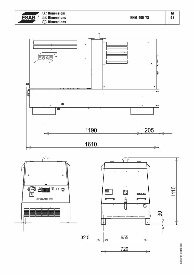
DimensioniDimensionsDimensions
KHM 405 YSM53
2051190
1610
720
65532.5
30
1110
KHM 405 YS
30/0
1/08
794
12-G
B
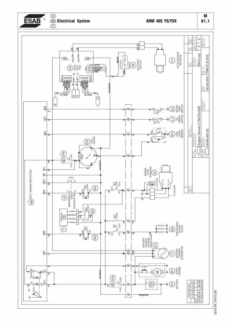
Electrical System KHM 405 YS/YSX
30/0
1/08
794
12-G
B
M61.1
KH
M405
YS
Engin
eY
anm
ar
3T
NV
76-H
GE
79412.p
rg
79
41
2.S
.01
0
2 Appr
ovat
o:
Esp.
Data
Dis.
Appr.
Modifica
Denominazione:
Macchina:
Data:
Progetto:
din°
Pag.n°
5
Date
Appr
.
Appr
oved
:
Proj
ect:
Deno
mina
tion
:
Mach
ine:
Modi
fica
tion
Date
:
DaPag.
Alla
Pag.
ToPage
From
Page
Designer:
ofn°
Desi.
Dis.
n°:
Exp.
Page
n°
Dwg.
n°:
Disegnatore:
11
nero/black
ne
ro/b
lac
k
55
9
ne
ro/b
lac
k
9
STA
RT
ER
KE
Y
OF
F
ON
30
15
/54
30
/11
55
0
ST
3-
+4
2
11
11
11
11
2
2
P4
5A
10
12
12
2
16
6
10
12
16 1
1
13
14
15
-+
S1
-+ M R1
G4
7
B+
IGL T1
U1
51
7
K2
(30
)
(87
)(8
7a
)
sto
pK
1(3
0)
(87
)(8
7a
)
Pr.
10
77
9
34
17
17
RED
RED/WHITE
YELLOW
BLACK
sto
pS
ole
no
idI7
tim
er
18
19
K3
N3T
ime
r
12
68
34
68
63
4
8
34
68
2107
K3
Tim
er5
Wh
iteR
ed
G1
OF
FO
N
STA
RT
15
15
/54
50
30
30
/1
-+
C2
P4
30
A
EN
GIN
EP
RO
TE
CT
ION
(EP
7)
H8
9
06.0
9.2
007
C.B
.
C.B
.
(1)
(2)
(3)
(4)
L5
BA
TT
ER
YS
TA
RT
EN
GIN
EB
AT
TE
RY
CH
AR
GE
ALT
ER
NA
TO
R
PR
EH
EA
TIN
GG
LO
WS
PL
UG
S
FU
EL
LE
VE
L
SE
ND
ER
WA
TE
RT
EM
P.
SW
ITC
H
OIL
PR
ES
S.
SW
ITC
H
EM
ER
GE
NC
YS
TO
P
PU
SH
-BU
TT
ON
HO
LD
CO
IL
PU
LL
CO
IL
WH
ITE
WIR
E
RE
DW
IRE
E1
FU
EL
GA
UG
E
EN
GIN
ES
TO
P
SO
LE
NO
ID
BA
TT
ER
Y
CH
AR
GE
VO
LTA
GE
RE
GU
LA
TO
R
L1
n.c
.
H1
n.o
.
ne
ro/b
lac
k
AC
CE
LE
RA
TIO
N
SO
LE
NO
ID
AU
TO
IDL
EP
CB
AU
TO
IDL
E
RP
MM
AX
AU
TO
IDL
ES
WIT
CH
21
20
21
20
3 364
RE
DW
HIT
EY
EL
LO
WB
LU
E
(HALL2)
RE
DW
HIT
EY
EL
LO
WB
LU
E
(HALL1)
REDWHITE
YELLOW
BLUE
RE
D
WH
ITE
F1
SO
L
SO
L -BATT
TA
TA
HA
LL
1
HA
LL
2
SW
+BATT
1
12
346 5
23
45
67
8
1 32 4
56
78
L8
I8
K1
(86
)
(85
)
N3
Pr.
K2
(86
)
(85
) N3sto
p
4
5
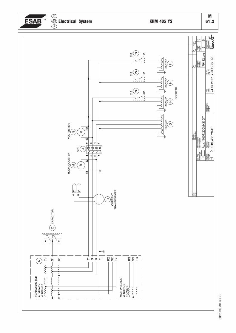
Electrical System KHM 405 YS
30/0
1/08
794
12-G
B
M61.2
KH
M405
YS
-CT
Aux.(4
00T
/230M
x3)
DT
79412.p
rg
79
41
2.S
.02
0
3 App
rova
to:
Esp
.D
ata
Dis
.A
ppr.
Mod
ifica
Den
omin
azio
ne:
Mac
chin
a:D
ata:
Pro
getto
:di
n°P
ag.n
°
5
Dat
eA
ppr.
App
rove
d:
Pro
ject
:D
enom
inat
ion:
Mac
hine
:
Mod
ifica
tion
Dat
e:
Da
Pag
.
Alla
Pag
.To
Pag
e
From
Pag
e
Des
igne
r:
ofn°
Des
i.
Dis
. n°:
Exp
.
Pag
en°
Dw
g.n°
:D
iseg
nato
re:
T1
S1
R1 Y T2
S2
54
53
RS
SS
TS
A R2
22
T S R
VN
IdIdIdId
N
N
D
40
0V
/32
A
G
23
0V
/32
A
H
C
U
30
AP4
23
0V
/16
A
H
23
0V
/16
A
H
51
52
hM
16
AP4
16
AP4
T S R Y
T S R Y
4 6
EX
CIT
AT
ION
AN
D
AU
XIL
IAR
YW
IND
ING
S
MA
INW
ELD
ING
WIN
DIN
GS
(PO
WE
R)
CA
PA
CIT
OR
HO
UR
-CO
UN
TE
R
CU
RR
EN
T
TR
AN
SF
OR
ME
R
G.F
.I.
C.B
.C
.B.
SO
CK
ET
S
C.B
.
VO
LT
ME
TE
R
24.0
7.2
007
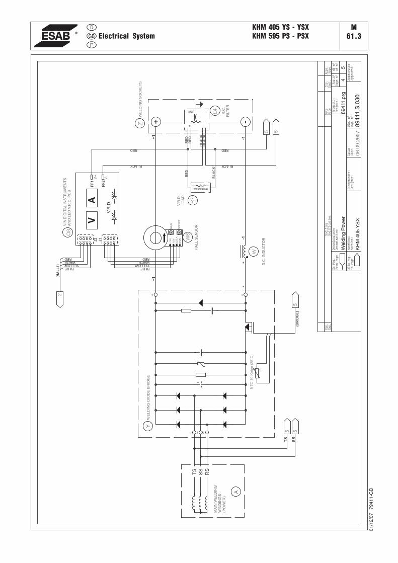
Electrical SystemKHM 405 YS - YSXKHM 595 PS - PSX
01/1
2/07
79
411-
GB
M61.3
KH
M405
YS
X
Weld
ing
Pow
er
89411.p
rg
89
411
.S.0
30
4 Appr
ovat
o:
Esp.
Data
Dis.
Appr
.Mo
difi
ca
Deno
mina
zion
e:
Macc
hina
:Da
ta:
Prog
etto
:di
n°Pa
g.n°
5
Date
Appr
.
Appr
oved
:
Proj
ect:
Deno
mina
tion
:
Mach
ine:
Modi
fica
tion
Date
:
DaPa
g.
Alla
Pag.
ToPa
ge
From
Page
Desi
gner
:
ofn°
Desi
.
Dis.
n°:
Exp.
Page
n°
Dwg.
n°:
Dise
gnat
ore:
06.0
9.2
007
RS
SS
TS
A
Y
-
TS
SS
5 55
-
+1
+1
-1-1
MA
INW
EL
DIN
G
WIN
DIN
GS
(PO
WE
R)
WE
LD
ING
DIO
DE
BR
IDG
E
D.C
.IN
DU
CT
OR
WE
LD
ING
SO
CK
ET
S
HA
LL
SE
NS
OR
BLUEYELLOWWHITERED
(BR
IDG
E)
-+Z
+
NT
C1
0K
oh
m(2
5°C
)
t°
~ ~ ~
+ -
W
+15V
OU
TA
GN
D
-15V
GA
IN
OF
FS
ET
W6
BLUEYELLOW
WHITERED
V/A
DIG
ITA
LIN
ST
RU
ME
NT
SA
ND
LE
DV
.R.D
.P
CB
J2
J1
VA
FF
2
FF
1
V.R
.D.
1 3 5 7
2 4 6 8
1 3 5 7
2 4 6 8
V+
V-
O8
RED
BLACK
V.R
.D.
LO
AD
150ohm/50W
R7
RED
BLACK
RE
D
BL
AC
K
RE
D
BL
AC
K
BL
AC
K
RE
D
5 5
2(H
AL
L1)
+ -
GND
L4
R.C
.
FIL
TE
R
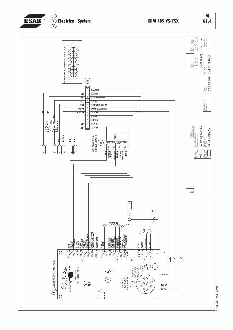
Electrical System KHM 405 YS-YSX
01/1
2/07
79
411-
GB
M61.4
KH
M405
YS
X
Weld
ing
Contr
ol
89411.p
rg
89
411
.S.0
40
5 Appr
ovat
o:
Esp.
Data
Dis.
Appr
.Mo
difi
ca
Deno
mina
zion
e:
Macc
hina
:Da
ta:
Prog
etto
:di
n°Pa
g.n°
5
Date
Appr
.
Appr
oved
:
Proj
ect:
Deno
mina
tion
:
Mach
ine:
Modi
fica
tion
Date
:
DaPa
g.
Alla
Pag.
ToPa
ge
From
Page
Desi
gner
:
ofn°
Desi
.
Dis.
n°:
Exp.
Page
n°
Dwg.
n°:
Dise
gnat
ore:
51
52
BLACK
44
51
52
TS
TS
SS
SS
WHITE
WHITE-ORANGE
VIOLET
GREY
BLACK
BLUE
WHITE-BLACK
WHITE-YELLOW
BROWN
BLACK
SS
SS
TS
RE
D
WH
ITE
BL
UE
PIN
K
GR
EE
N
YE
LL
OW
BL
AC
K
OR
AN
GE
WE
LD
ING
CU
RR
EN
TR
EG
UL
AT
OR
RE
MO
TE
CO
NT
RO
L
SO
CK
ET
WE
LD
ING
CO
NT
RO
LP.C
.B.
WE
LD
ING
P.C
.B.
TR
AN
SF
OR
ME
R
C.B
.
WE
LD
ING
SE
LE
CT
OR
MO
DE
BLUE
WHITE
BLACK
19
41
211
6
P4
10
A
16
10
71
4
22
0V
26
V
18
V
18
V
10
V
E
8
06.0
9.2
007
B C
DE
FG
H I J
A
P3
P1
P2
P5
P4
T
X1
STA
ND
BY
TIG
ON
Q7
MA
X
50
% I3
RA
NG
E
CU
RR
EN
TC
C
12
34
56
78
91
0
111
2
13
14
15
16
12
34
56
78
91
0
111
2
13
14
12
34
56
78
R
RE
DG
RE
EN
WH
ITE
YE
LL
OW
BL
AC
KB
LU
E
OR
AN
GE
PIN
K
WH
ITE
-RE
D
BR
OW
NW
HIT
E-B
LA
CK
WH
ITE
-OR
AN
GE
WH
ITE
-YE
LL
OW
GR
EY
VIO
LE
T
12
34
56
78
910
1112
1314
1516
16
PIN
MO
LE
XF
EM
AL
CO
NN
EC
TO
R
B
RE
D
WH
ITE
YE
LL
OW
BL
UE
(BRIDGE)
OR
AN
GE
(G1
)Y
EL
LO
W(S
2)
WH
ITE
(G3
)B
LA
CK
(S4)
BR
OW
N(G
5)
BL
UE
(S6
)G
RE
EN
(G7
)R
ED
(S8
)G
RE
Y(G
9)
PIN
K(S
10)
VIO
LE
TA
ZU
R
RE
D
BL
AC
K
BLACK
BLACK
RED
3 34 4
4
2
(HALL2)


ESAB subsidiaries and representative offices
Europe
AUSTRIAESAB Ges.m.b.H Vienna--LiesingTel: +43 1 888 25 11 Fax: +43 1 888 25 11 85
BELGIUM S.A. ESAB N.V. Brussels Tel: +32 2 745 11 00 Fax: +32 2 726 80 05
THE CZECH REPUBLIC ESAB VAMBERK s.r.o. PragueTel: +420 2 819 40 885 Fax: +420 2 819 40 120
DENMARKAktieselskabet ESAB Copenhagen--Valby Tel:+45 36 30 01 11 Fax:+45 36 30 40 03
FINLAND ESAB Oy Helsinki Tel: +358 9 547 761 Fax: +358 9 547 77 71
FRANCE ESAB France S.A. Cergy Pontoise Tel:+33 1 30 75 55 00 Fax:+33 1 30 75 55 24
GERMANYESAB GmbH SolingenTel: +49 212 298 0 Fax: +49 212 298 204
GREAT BRITAIN ESAB Group (UK) Ltd Waltham Cross Tel: +44 1992 76 85 15 Fax: +44 1992 71 58 03 ESAB Automation Ltd Andover Tel: +44 1264 33 22 33 Fax: +44 1264 33 20 74
HUNGARY ESAB Kft BudapestTel:+36 1 20 44 182 Fax:+36 1 20 44 186
ITALYESAB Saldatura S.p.A. Mesero (Mi) Tel:+39 02 97 96 81 Fax:+39 02 97 28 91 81
THE NETHERLANDS ESAB Nederland B.V. Utrecht Tel: +31 30 248 59 22 Fax: +31 30 248 52 60
NORWAYAS ESAB Larvik Tel:+47 33 12 10 00 Fax:+47 33 11 52 03
POLAND ESAB Sp.z.o.o Warszaw Tel: +48 22 813 99 63 Fax: +48 22 813 98 81
PORTUGAL ESAB Lda LisbonTel: +351 1 837 1527 Fax: +351 1 859 1277
SLOVAKIA ESAB Slovakia s.r.o. Bratislava Tel:+421 7 44 88 24 26 Fax:+421 7 44 88 87 41
SPAINESAB Ibérica S.A. Alcobendas (Madrid) Tel: +34 91 623 11 00 Fax: +34 91 661 51 83
SWEDENESAB Sverige AB Gothenburg Tel:+46 31 50 95 00 Fax:+46 31 50 92 22
ESAB International AB Gothenburg Tel:+46 31 50 90 00 Fax:+46 31 50 93 60
SWITZERLAND ESAB AG DietikonTel: +41 1 741 25 25 Fax: +41 1 740 30 55
North and South America
ARGENTINA CONARCO Buenos Aires Tel: +54 11 4 753 4039 Fax: +54 11 4 753 6313
BRAZIL ESAB S.A. Contagem--MG Tel: +55 31 333 43 33 Fax: +55 31 361 31 51
CANADA ESAB Group Canada Inc. Missisauga, Ontario Tel: +1 905 670 02 20 Fax: +1 905 670 48 79
MEXICO ESAB Mexico S.A. Monterrey Tel: +52 8 350 5959 Fax: +52 8 350 7554
USAESAB Welding & Cutting Products Florence, SC Tel: +1 843 669 44 11 Fax: +1 843 664 44 58
Asia/Pacific
AUSTRALIA ESAB Australia Pty Ltd ErmingtonTel: +61 2 9647 1232 Fax: +61 2 9748 1685
CHINAShanghai ESAB A/P ShanghaiTel: +86 21 6539 7124 Fax: +86 21 6543 6622
INDIAESAB India Ltd CalcuttaTel: +91 33 478 45 17 Fax: +91 33 468 18 80
INDONESIAP.T. Esabindo Pratama Jakarta Tel: +62 21 460 01 88 Fax: +62 21 461 29 29
MALAYSIAESAB (Malaysia) Snd Bhd SelangorTel: +60 3 703 36 15 Fax: +60 3 703 35 52
SINGAPORE ESAB Singapore Pte Ltd SingaporeTel: +65 861 43 22 Fax: +65 861 31 95
ESAB Asia/Pacific Pte Ltd SingaporeTel: +65 861 74 42 Fax: +65 863 08 39
SOUTH KOREA ESAB SeAH Corporation Kyung--NamTel: +82 551 289 81 11 Fax: +82 551 289 88 63
THAILAND ESAB (Thailand) Ltd Samutprakarn Tel: +66 2 393 60 62 Fax: +66 2 748 71 11
UNITED ARAB EMIRATES ESAB Middle East DubaiTel: +971 4 338 88 29 Fax: +971 4 338 87 29
Representative offices
BULGARIA ESAB Representative Office SofiaTel/Fax: +359 2 974 42 88
EGYPT ESAB Egypt Dokki--Cairo Tel: +20 2 390 96 69 Fax: +20 2 393 32 13
ROMANIA ESAB Representative Office BucharestTel/Fax: +40 1 322 36 74
RUSSIA - CIS ESAB Representative Office Moscow Tel: +7 095 937 98 20 Fax: +7 095 937 95 80 ESAB Representative Office St Petersburg Tel: +7 812 325 43 62 Fax: +7 812 325 66 85
Distributors For addresses and phone numbers to our distributors in other countries, please visit our home page
www.esab.com
ESAB AB SSC Nordic Region Box 80040 S-402 77 Göteborg SWEDENPhone + 46 31 509000 Fax +46 31 509195
www.esab.com050211


![]Ys}˝‡—dUeconweb.ucsd.edu/~v2crawford/Camerer_Ch1intro.pdf]Ys}˝‡—dU ... d(d](https://img.pdfslide.tips/doc/110x75/613063f61ecc515869441112/-ysaa-v2crawfordcamererch1intropdf-ysaadu-dd.jpg)