Embed Size (px)
Citation preview
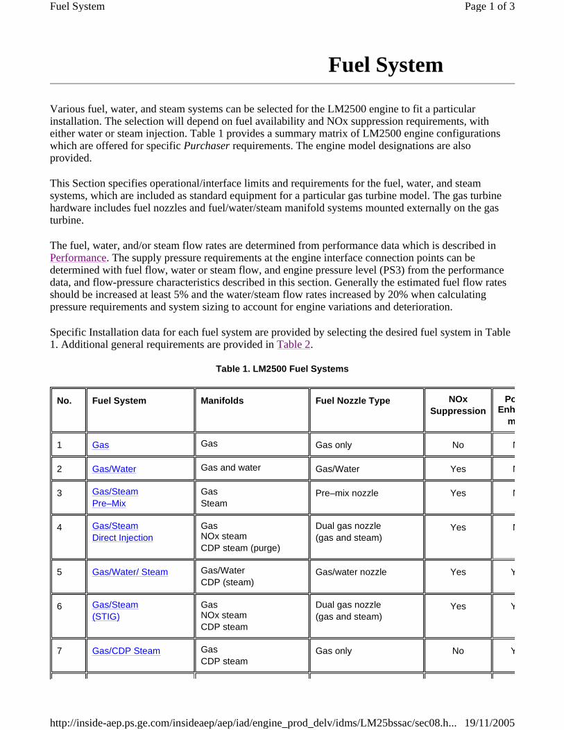
Various fuel, water, and steam systems can be selected for the LM2500 engine to fit a particular installation. The selection will depend on fuel availability and NOx suppression requirements, with either water or steam injection. Table 1 provides a summary matrix of LM2500 engine configurations which are offered for specific Purchaser requirements. The engine model designations are also provided.
This Section specifies operational/interface limits and requirements for the fuel, water, and steam systems, which are included as standard equipment for a particular gas turbine model. The gas turbine hardware includes fuel nozzles and fuel/water/steam manifold systems mounted externally on the gas turbine.
The fuel, water, and/or steam flow rates are determined from performance data which is described in Performance. The supply pressure requirements at the engine interface connection points can be determined with fuel flow, water or steam flow, and engine pressure level (PS3) from the performance data, and flow-pressure characteristics described in this section. Generally the estimated fuel flow rates should be increased at least 5% and the water/steam flow rates increased by 20% when calculating pressure requirements and system sizing to account for engine variations and deterioration.
Specific Installation data for each fuel system are provided by selecting the desired fuel system in Table 1. Additional general requirements are provided in Table 2.
Table 1. LM2500 Fuel Systems
Fuel System
No. Fuel System Manifolds Fuel Nozzle Type NOx Suppression
Power Enhance
m
1 Gas Gas Gas only No N
2 Gas/Water Gas and water Gas/Water Yes N
3 Gas/Steam Pre–Mix
Gas Steam
Pre–mix nozzle Yes N
4 Gas/Steam Direct Injection
Gas NOx steam CDP steam (purge)
Dual gas nozzle (gas and steam)
Yes N
5 Gas/Water/ Steam Gas/Water CDP (steam)
Gas/water nozzle Yes Y
6 Gas/Steam(STIG)
Gas NOx steam CDP steam
Dual gas nozzle (gas and steam)
Yes Y
7 Gas/CDP Steam Gas CDP steam
Gas only No Y
Page 1 of 3Fuel System
19/11/2005http://inside-aep.ps.ge.com/insideaep/aep/iad/engine_prod_delv/idms/LM25bssac/sec08.h...

8 Liquid Single liquid fuel Liquid fuel only with integral flow divider valves
No N
9 Liquid/Water Primary, secondary and water mixing tee
Liquid/water with off–engine fuel pressurizing valve
Yes N
10 Liquid/ Water/ Steam(Mixed Mode)
Same as liquid/water, plus CDP steam
Liquid/water with off–engine pressurizing valve
Yes Y
11 Liquid/ CDP Steam Single liquid fuel CDP steam
Liquid fuel only with integral flow divider valves
No Y
12 Dual Fuel Same as liquid/water plus gas
Dual fuel with off–engine liquid fuel pressurizing valve
No N
13 Dual Fuel/ Water Same as liquid/water plus gas
Dual fuel with off–engine liquid fuel pressurizing valve
Yes N
14 Dual Fuel/ Water/Steam
Same as liquid/water plus Gas CDP steam
Dual fuel with off–engine liquid fuel pressurizing valve
Yes Y
15 Dual Fuel/ CDP Steam
Same as dual fuel CDP steam
Dual fuel with off–engine liquid fuel pressurizing valve
No Y
16 Dual Fuel/ Steam Pre-Mix
Same as dual fuel plus steam
Dual fuel-Steam with off–engine liquid fuel pressurizing valve
Yes N
17 Dual Fuel/ Steam Pre-Mix plus CDP Steam
Same as dual fuel plus steam CDP Steam
Dual fuel-Steam with off–engine liquid fuel pressurizing valve
Yes Y
Table 2 - General Requirements
Gas Fuel Requirements Liquid Fuel Requirements
NOx Abatement Water Requirements NOx Abatement Steam Requirements
,1'(; %$&.�72�723 +20(
Page 2 of 3Fuel System
19/11/2005http://inside-aep.ps.ge.com/insideaep/aep/iad/engine_prod_delv/idms/LM25bssac/sec08.h...

Page 3 of 3Fuel System
19/11/2005http://inside-aep.ps.ge.com/insideaep/aep/iad/engine_prod_delv/idms/LM25bssac/sec08.h...


