Embed Size (px)
Citation preview
Spur Gear
2103320 Des Mach Elem Mech. Eng. Department
Chulalongkorn University
Gear force analysis (1)
Pinion
Gear
Base circle Pitch circle
Pressure line
φ
Pinion
Pressure line
φ
F
Fb
Fr
Gear
Pressure line φ
F
Fb
Fr
FBD
Neglect sliding friction in FBD
Gear force analysis (2)
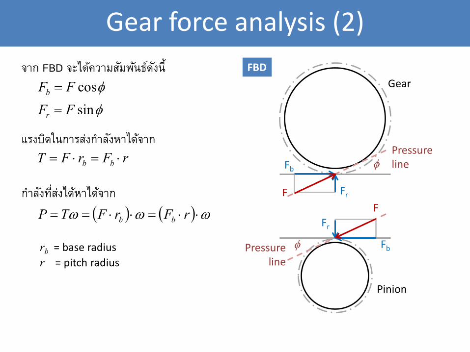
φcosFFb =
φsinFFr =
rFrFT bb ⋅=⋅=
Pinion
Pressure line
φ
F
Fb
Fr
Gear
Pressure line φ
F
Fb
Fr
FBD
( ) ( ) ωωω ⋅⋅=⋅⋅== rFrFTP bb
จาก FBD จะไดค้วามสมัพนัธด์งัน้ี
แรงบดิในการสง่กําลงัหาไดจ้าก
กาํลงัทีส่ง่ไดห้าไดจ้าก
rb = base radius
r = pitch radius
Gear tooth strength
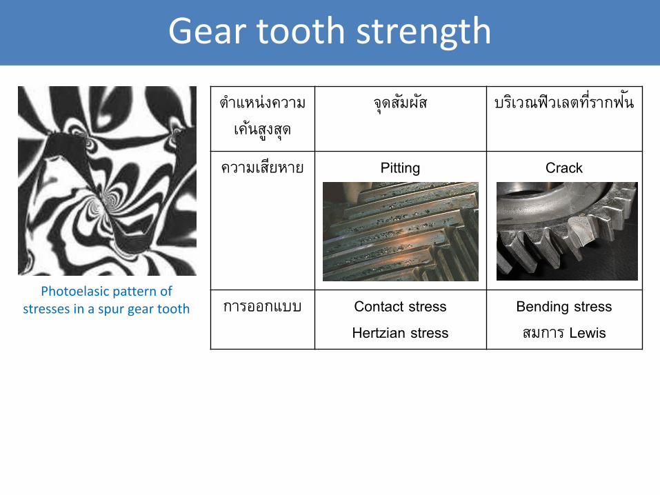
Photoelasic pattern of stresses in a spur gear tooth
ตาํแหน่งความ
เคน้สงูสดุ
จดุสมัผสั บรเิวณฟิวเลตทีร่ากฟนั
ความเสยีหาย Pitting
Crack
การออกแบบ Contact stress
Hertzian stress
Bending stress
สมการ Lewis
Gear tooth bending stress (1)
Fb
L
t
b
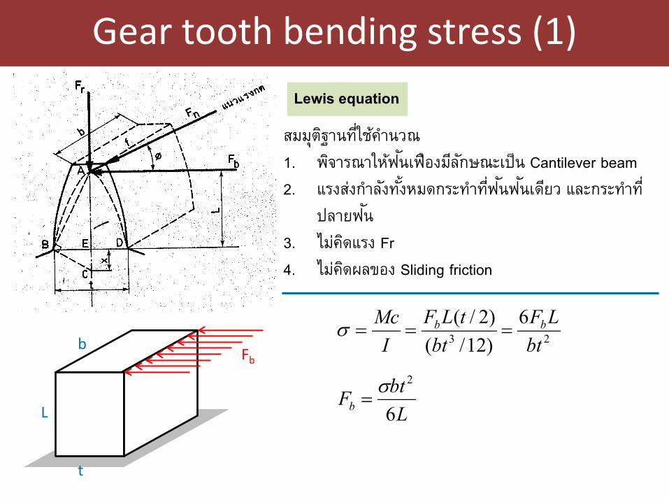
Lewis equation
สมมตุฐิานทีใ่ชค้าํนวณ
1. พจิารณาใหฟ้นัเฟืองมลีกัษณะเป็น Cantilever beam
2. แรงสง่กาํลงัทัง้หมดกระทาํทีฟ่นัฟนัเดยีว และกระทาํที่
ปลายฟนั
3. ไมค่ดิแรง Fr
4. ไมค่ดิผลของ Sliding friction
23
6)12/()2/(
btLF
bttLF
IMc bb ===σ
LbtFb 6
2σ=
Gear tooth bending stress (2)
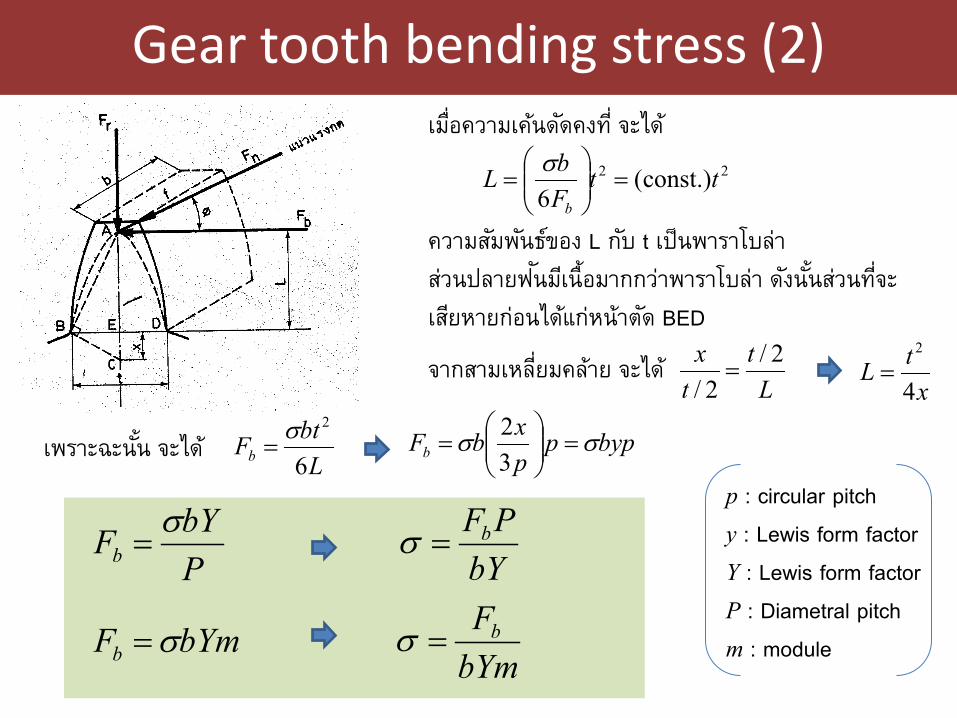
เมือ่ความเคน้ดดัคงที ่จะได ้
22 const.)(6
ttFbL
b
=
=
σ
ความสมัพนัธข์อง L กบั t เป็นพาราโบล่า
สว่นปลายฟนัมเีน้ือมากกวา่พาราโบล่า ดงันัน้สว่นทีจ่ะ
เสยีหายก่อนไดแ้ก่หน้าตดั BED
จากสามเหลีย่มคลา้ย จะได ้
LbtFb 6
2σ=
Lt
tx 2/2/=
xtL4
2
=
เพราะฉะนัน้ จะได ้ bypppxbFb σσ =
=
32
p : circular pitch
y : Lewis form factor
Y : Lewis form factor
P : Diametral pitch
m : module
PbYFb
σ=
bYmFb σ=
bYPFb=σ
bYmFb=σ
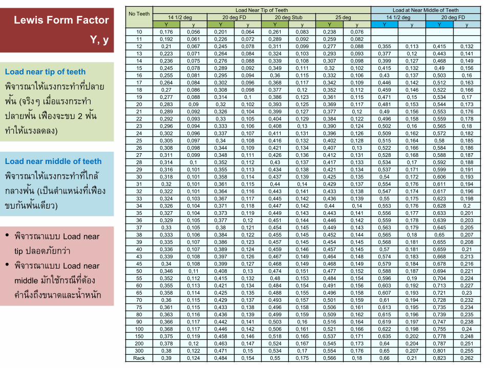
No Teeth Load Near Tip of Teeth Load at Near Middle of Teeth
14 1/2 deg 20 deg FD 20 deg Stub 25 deg 14 1/2 deg 20 deg FD Y y Y y Y y Y y Y y Y y
10 0,176 0,056 0,201 0,064 0,261 0,083 0,238 0,076 11 0,192 0,061 0,226 0,072 0,289 0,092 0,259 0,082 12 0,21 0,067 0,245 0,078 0,311 0,099 0,277 0,088 0,355 0,113 0,415 0,132 13 0,223 0,071 0,264 0,084 0,324 0,103 0,293 0,093 0,377 0,12 0,443 0,141 14 0,236 0,075 0,276 0,088 0,339 0,108 0,307 0,098 0,399 0,127 0,468 0,149 15 0,245 0,078 0,289 0,092 0,349 0,111 0,32 0,102 0,415 0,132 0,49 0,156 16 0,255 0,081 0,295 0,094 0,36 0,115 0,332 0,106 0,43 0,137 0,503 0,16 17 0,264 0,084 0,302 0,096 0,368 0,117 0,342 0,109 0,446 0,142 0,512 0,163 18 0,27 0,086 0,308 0,098 0,377 0,12 0,352 0,112 0,459 0,146 0,522 0,166 19 0,277 0,088 0,314 0,1 0,386 0,123 0,361 0,115 0,471 0,15 0,534 0,17 20 0,283 0,09 0,32 0,102 0,393 0,125 0,369 0,117 0,481 0,153 0,544 0,173 21 0,289 0,092 0,326 0,104 0,399 0,127 0,377 0,12 0,49 0,156 0,553 0,176 22 0,292 0,093 0,33 0,105 0,404 0,129 0,384 0,122 0,496 0,158 0,559 0,178 23 0,296 0,094 0,333 0,106 0,408 0,13 0,390 0,124 0,502 0,16 0,565 0,18 24 0,302 0,096 0,337 0,107 0,411 0,131 0,396 0,126 0,509 0,162 0,572 0,182 25 0,305 0,097 0,34 0,108 0,416 0,132 0,402 0,128 0,515 0,164 0,58 0,185 26 0,308 0,098 0,344 0,109 0,421 0,134 0,407 0,13 0,522 0,166 0,584 0,186 27 0,311 0,099 0,348 0,111 0,426 0,136 0,412 0,131 0,528 0,168 0,588 0,187 28 0,314 0,1 0,352 0,112 0,43 0,137 0,417 0,133 0,534 0,17 0,592 0,188 29 0,316 0,101 0,355 0,113 0,434 0,138 0,421 0,134 0,537 0,171 0,599 0,191 30 0,318 0,101 0,358 0,114 0,437 0,139 0,425 0,135 0,54 0,172 0,606 0,193 31 0,32 0,101 0,361 0,115 0,44 0,14 0,429 0,137 0,554 0,176 0,611 0,194 32 0,322 0,101 0,364 0,116 0,443 0,141 0,433 0,138 0,547 0,174 0,617 0,196 33 0,324 0,103 0,367 0,117 0,445 0,142 0,436 0,139 0,55 0,175 0,623 0,198 34 0,326 0,104 0,371 0,118 0,447 0,142 0,44 0,14 0,553 0,176 0,628 0,2 35 0,327 0,104 0,373 0,119 0,449 0,143 0,443 0,141 0,556 0,177 0,633 0,201 36 0,329 0,105 0,377 0,12 0,451 0,144 0,446 0,142 0,559 0,178 0,639 0,203 37 0,33 0,105 0,38 0,121 0,454 0,145 0,449 0,143 0,563 0,179 0,645 0,205 38 0,333 0,106 0,384 0,122 0,455 0,145 0,452 0,144 0,565 0,18 0,65 0,207 39 0,335 0,107 0,386 0,123 0,457 0,145 0,454 0,145 0,568 0,181 0,655 0,208 40 0,336 0,107 0,389 0,124 0,459 0,146 0,457 0,145 0,57 0,181 0,659 0,21 43 0,339 0,108 0,397 0,126 0,467 0,149 0,464 0,148 0,574 0,183 0,668 0,213 45 0,34 0,108 0,399 0,127 0,468 0,149 0,468 0,149 0,579 0,184 0,678 0,216 50 0,346 0,11 0,408 0,13 0,474 0,151 0,477 0,152 0,588 0,187 0,694 0,221 55 0,352 0,112 0,415 0,132 0,48 0,153 0,484 0,154 0,596 0,19 0,704 0,224 60 0,355 0,113 0,421 0,134 0,484 0,154 0,491 0,156 0,603 0,192 0,713 0,227 65 0,358 0,114 0,425 0,135 0,488 0,155 0,496 0,158 0,607 0,193 0,721 0,23 70 0,36 0,115 0,429 0,137 0,493 0,157 0,501 0,159 0,61 0,194 0,728 0,232 75 0,361 0,115 0,433 0,138 0,496 0,158 0,506 0,161 0,613 0,195 0,735 0,234 80 0,363 0,116 0,436 0,139 0,499 0,159 0,509 0,162 0,615 0,196 0,739 0,235 90 0,366 0,117 0,442 0,141 0,503 0,16 0,516 0,164 0,619 0,197 0,747 0,238 100 0,368 0,117 0,446 0,142 0,506 0,161 0,521 0,166 0,622 0,198 0,755 0,24 150 0,375 0,119 0,458 0,146 0,518 0,165 0,537 0,171 0,635 0,202 0,778 0,248 200 0,378 0,12 0,463 0,147 0,524 0,167 0,545 0,173 0,64 0,204 0,787 0,251 300 0,38 0,122 0,471 0,15 0,534 0,17 0,554 0,176 0,65 0,207 0,801 0,255
Rack 0,39 0,124 0,484 0,154 0,55 0,175 0,566 0,18 0,66 0,21 0,823 0,262
Lewis Form Factor
Y, y
Load near tip of teeth
พจิารณาใหแ้รงกระทาํทีป่ลาย
ฟนั (จรงิๆ เมื่อแรงกระทาํ
ปลายฟนั เฟืองจะขบ 2 ฟนั
ทาํใหแ้รงลดลง)
Load near middle of teeth
พจิารณาใหแ้รงกระทาํทีใ่กล้
กลางฟนั (เป็นตําแหน่งทีเ่ฟือง
ขบกนัฟนัเดยีว)
• พจิารณาแบบ Load near
tip ปลอดภยักวา่
• พจิารณาแบบ Load near
middle มกัใชก้รณีทีต่อ้ง
คาํนึงถงึขนาดและน้ําหนกั
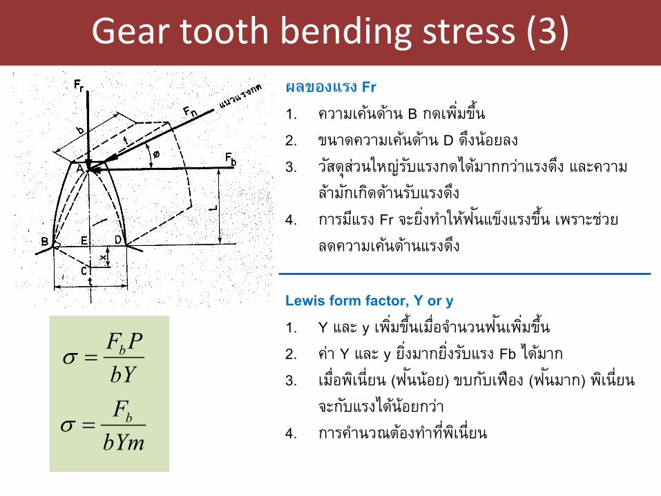
Gear tooth bending stress (3)
ผลของแรง Fr
1. ความเคน้ดา้น B กดเพิม่ขึน้
2. ขนาดความเคน้ดา้น D ดงึน้อยลง
3. วสัดุสว่นใหญ่รบัแรงกดไดม้ากกวา่แรงดงึ และความ
ลา้มกัเกดิดา้นรบัแรงดงึ
4. การมแีรง Fr จะยิง่ทาํใหฟ้นัแขง็แรงขึน้ เพราะชว่ย
ลดความเคน้ดา้นแรงดงึ
Lewis form factor, Y or y
1. Y และ y เพิม่ขึน้เมือ่จาํนวนฟนัเพิม่ขึน้
2. คา่ Y และ y ยิง่มากยิง่รบัแรง Fb ไดม้าก
3. เมือ่พเิน่ียน (ฟนัน้อย) ขบกบัเฟือง (ฟนัมาก) พเิน่ียน
จะกบัแรงไดน้้อยกวา่
4. การคาํนวณตอ้งทาํทีพ่เิน่ียน
bYPFb=σ
bYmFb=σ
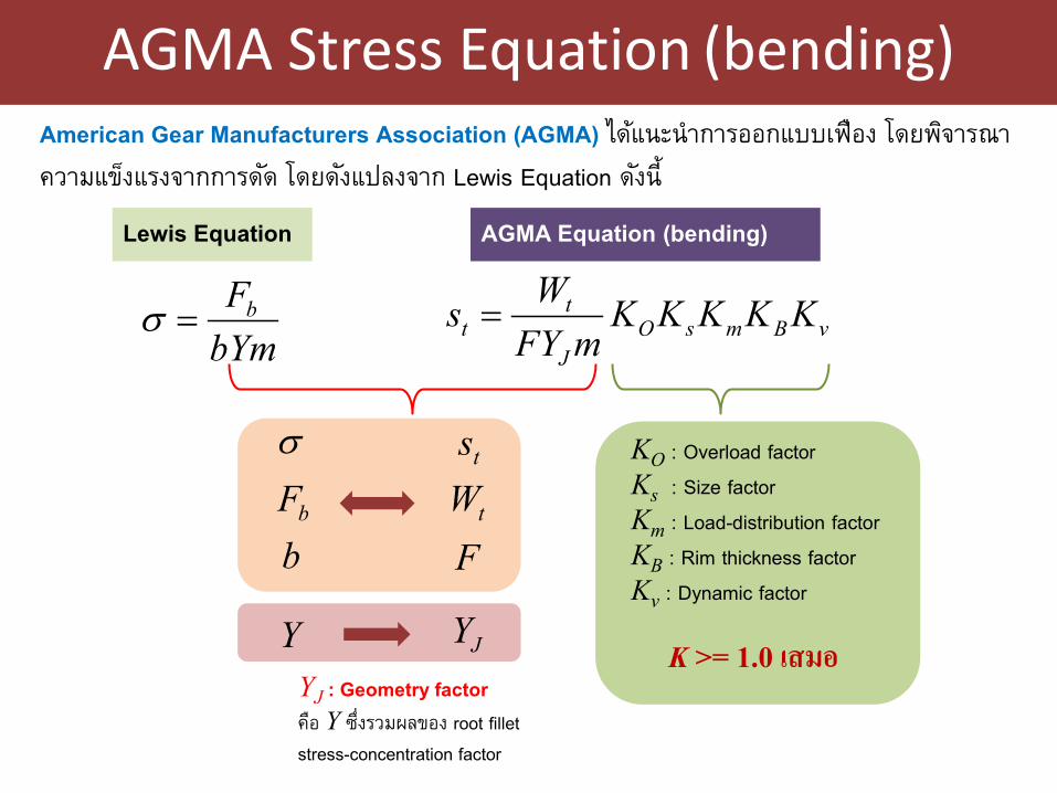
AGMA Stress Equation (bending)
American Gear Manufacturers Association (AGMA) ไดแ้นะนําการออกแบบเฟือง โดยพจิารณา
ความแขง็แรงจากการดดั โดยดงัแปลงจาก Lewis Equation ดงัน้ี
bYmFb=σ
Lewis Equation AGMA Equation (bending)
vBmsOJ
tt KKKKK
mFYWs =
Y JYYJ : Geometry factor คอื Y ซึง่รวมผลของ root fillet stress-concentration factor
KO : Overload factor
Ks : Size factor
Km : Load-distribution factor
KB : Rim thickness factor
Kv : Dynamic factor
K >= 1.0 เสมอ
σ
bFts
tWb F
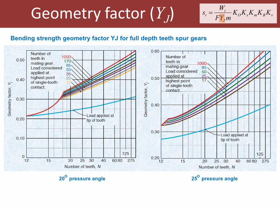
Geometry factor (YJ)
Bending strength geometry factor YJ for full depth teeth spur gears
vBmsOJ
tt KKKKK
mFYWs =
20° pressure angle 25° pressure angle
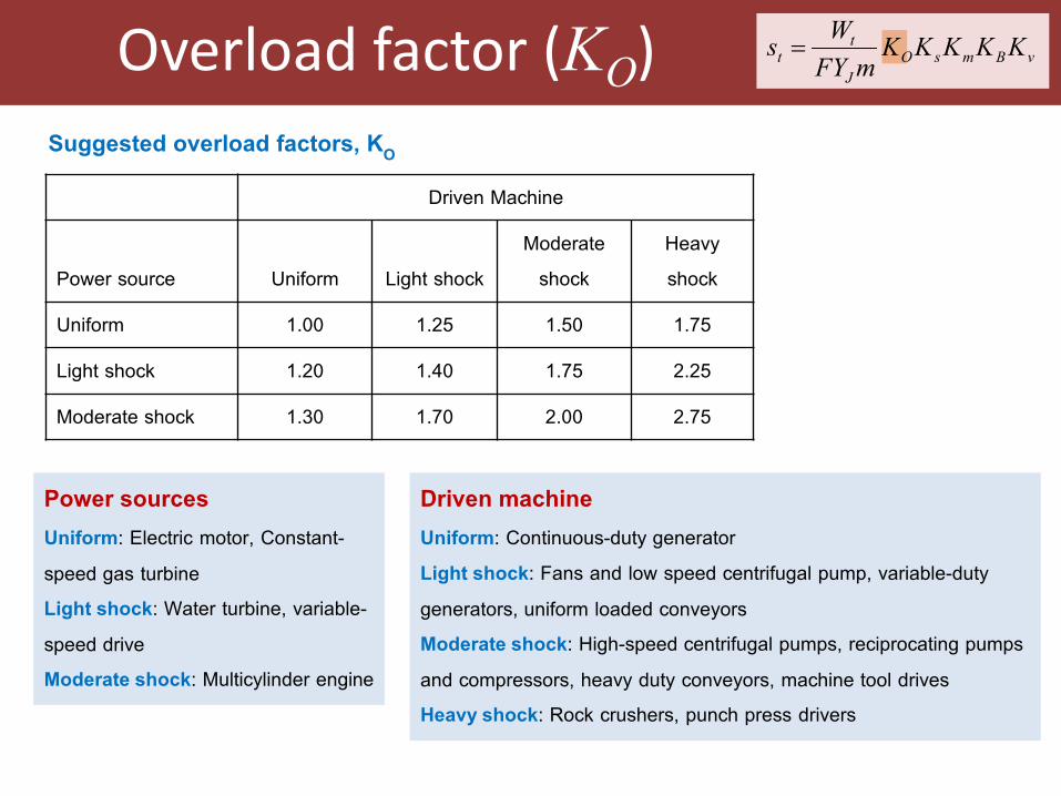
Overload factor (KO)
Suggested overload factors, KO
Driven Machine
Power source Uniform Light shock
Moderate
shock
Heavy
shock
Uniform 1.00 1.25 1.50 1.75
Light shock 1.20 1.40 1.75 2.25
Moderate shock 1.30 1.70 2.00 2.75
Power sources Uniform: Electric motor, Constant-
speed gas turbine
Light shock: Water turbine, variable-
speed drive
Moderate shock: Multicylinder engine
Driven machine Uniform: Continuous-duty generator
Light shock: Fans and low speed centrifugal pump, variable-duty
generators, uniform loaded conveyors
Moderate shock: High-speed centrifugal pumps, reciprocating pumps
and compressors, heavy duty conveyors, machine tool drives
Heavy shock: Rock crushers, punch press drivers
vBmsOJ
tt KKKKK
mFYWs =
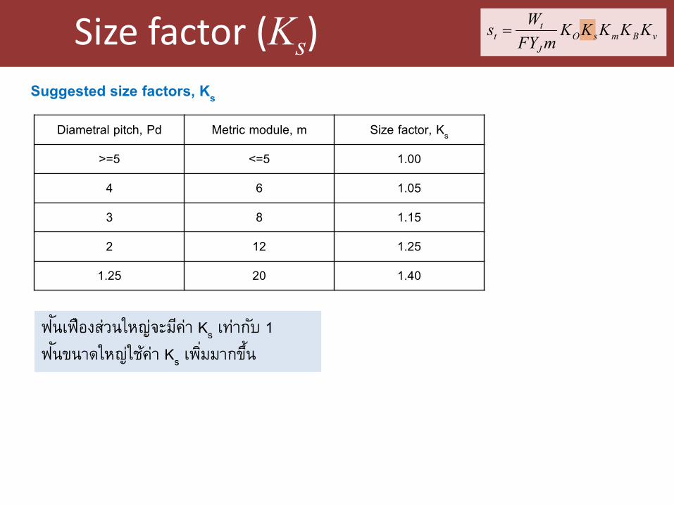
Size factor (Ks)
Suggested size factors, Ks
Diametral pitch, Pd Metric module, m Size factor, Ks
>=5 <=5 1.00
4 6 1.05
3 8 1.15
2 12 1.25
1.25 20 1.40
ฟนัเฟืองสว่นใหญ่จะมคีา่ Ks เทา่กบั 1
ฟนัขนาดใหญ่ใชค้า่ Ks เพิม่มากขึน้
vBmsOJ
tt KKKKK
mFYWs =
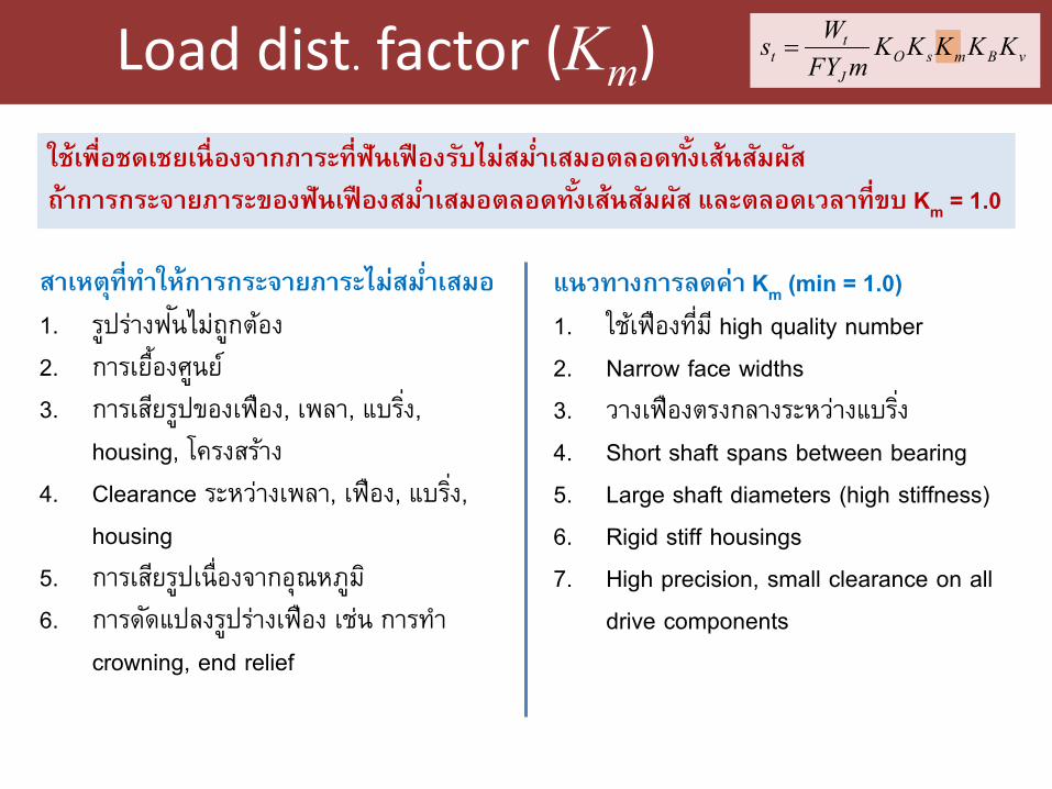
Load dist. factor (Km)
ใช้เพ่ือชดเชยเน่ืองจากภาระท่ีฟันเฟืองรบัไม่สมํา่เสมอตลอดทัง้เส้นสมัผสั
ถ้าการกระจายภาระของฟันเฟืองสมํา่เสมอตลอดทัง้เส้นสมัผสั และตลอดเวลาท่ีขบ Km = 1.0
สาเหตท่ีุทาํให้การกระจายภาระไมส่มํา่เสมอ
1. รปูรา่งฟนัไมถ่กูตอ้ง
2. การเยือ้งศนูย ์
3. การเสยีรปูของเฟือง, เพลา, แบริง่,
housing, โครงสรา้ง
4. Clearance ระหวา่งเพลา, เฟือง, แบริง่,
housing
5. การเสยีรปูเน่ืองจากอุณหภมู ิ
6. การดดัแปลงรปูรา่งเฟือง เชน่ การทาํ
crowning, end relief
แนวทางการลดค่า Km (min = 1.0)
1. ใชเ้ฟืองทีม่ ีhigh quality number
2. Narrow face widths
3. วางเฟืองตรงกลางระหวา่งแบริง่
4. Short shaft spans between bearing
5. Large shaft diameters (high stiffness)
6. Rigid stiff housings
7. High precision, small clearance on all
drive components
vBmsOJ
tt KKKKK
mFYWs =
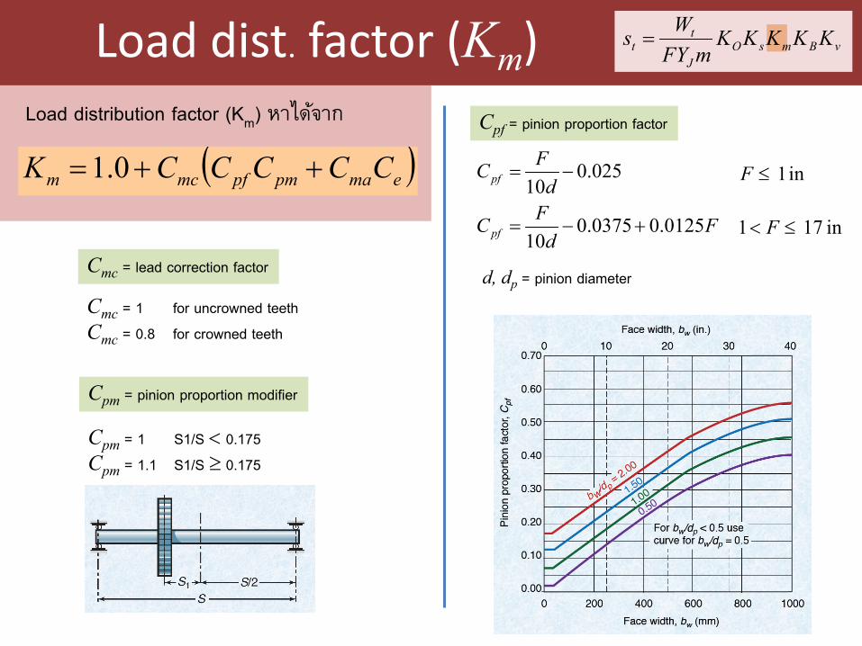
Load dist. factor (Km)
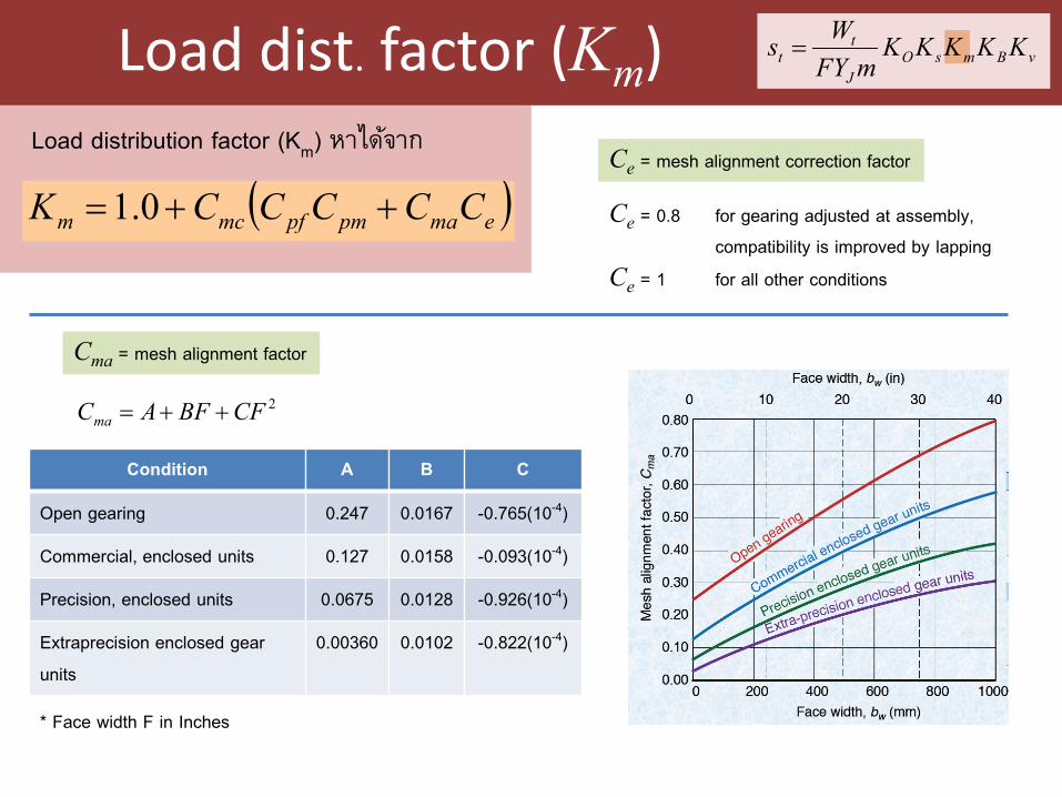
Load distribution factor (Km) หาไดจ้าก
( )emapmpfmcm CCCCCK ++= 0.1
Cmc = 1 for uncrowned teeth
Cmc = 0.8 for crowned teeth
Cmc = lead correction factor
Cpm = pinion proportion modifier
Cpm = 1 S1/S < 0.175
Cpm = 1.1 S1/S ≥ 0.175
Cpf = pinion proportion factor
025.010
−=d
FCpf
Fd
FCpf 0125.00375.010
+−=
in 1 ≤F
in 17 1 ≤< F
d, dp = pinion diameter
vBmsOJ
tt KKKKK
mFYWs =
Load dist. factor (Km)
Load distribution factor (Km) หาไดจ้าก
( )emapmpfmcm CCCCCK ++= 0.1
Cma = mesh alignment factor
Ce = mesh alignment correction factor
Ce = 0.8 for gearing adjusted at assembly, compatibility is improved by lapping
Ce = 1 for all other conditions
2CFBFACma ++=
Condition A B C
Open gearing 0.247 0.0167 -0.765(10-4)
Commercial, enclosed units 0.127 0.0158 -0.093(10-4)
Precision, enclosed units 0.0675 0.0128 -0.926(10-4)
Extraprecision enclosed gear
units
0.00360 0.0102 -0.822(10-4)
* Face width F in Inches
vBmsOJ
tt KKKKK
mFYWs =
Rim thickness factor (KB) vBmsOJ
tt KKKKK
mFYWs =
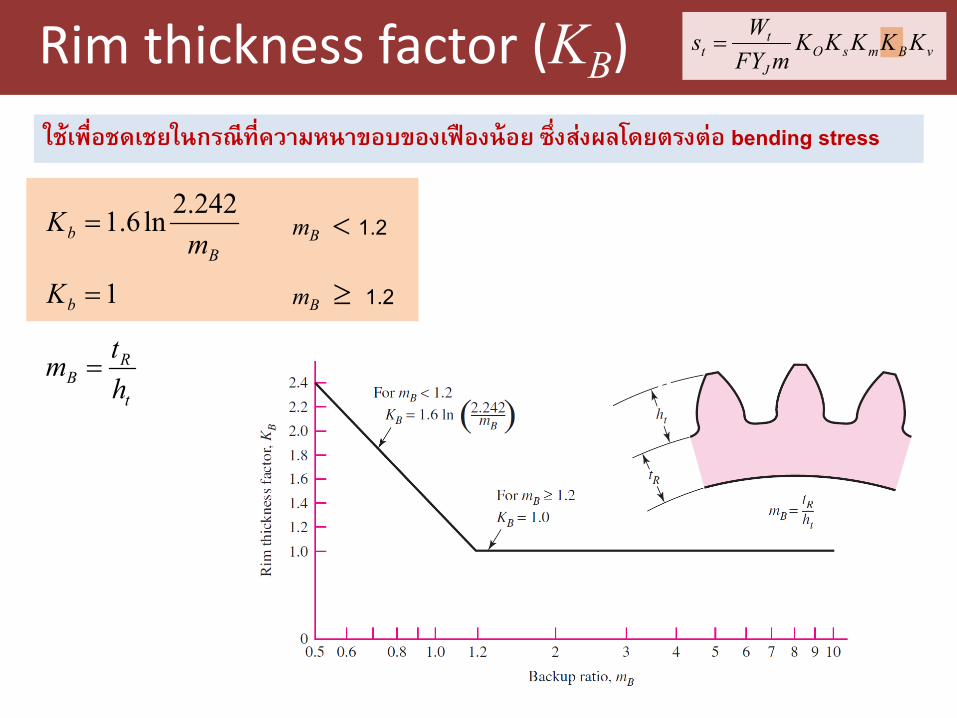
ใช้เพ่ือชดเชยในกรณีท่ีความหนาขอบของเฟืองน้อย ซ่ึงส่งผลโดยตรงต่อ bending stress
Bb m
K 242.2ln6.1=
1=bK mB ≥ 1.2
mB < 1.2
t
RB h
tm =
Dynamic factor (Kv) vBmsOJ
tt KKKKK
mFYWs =
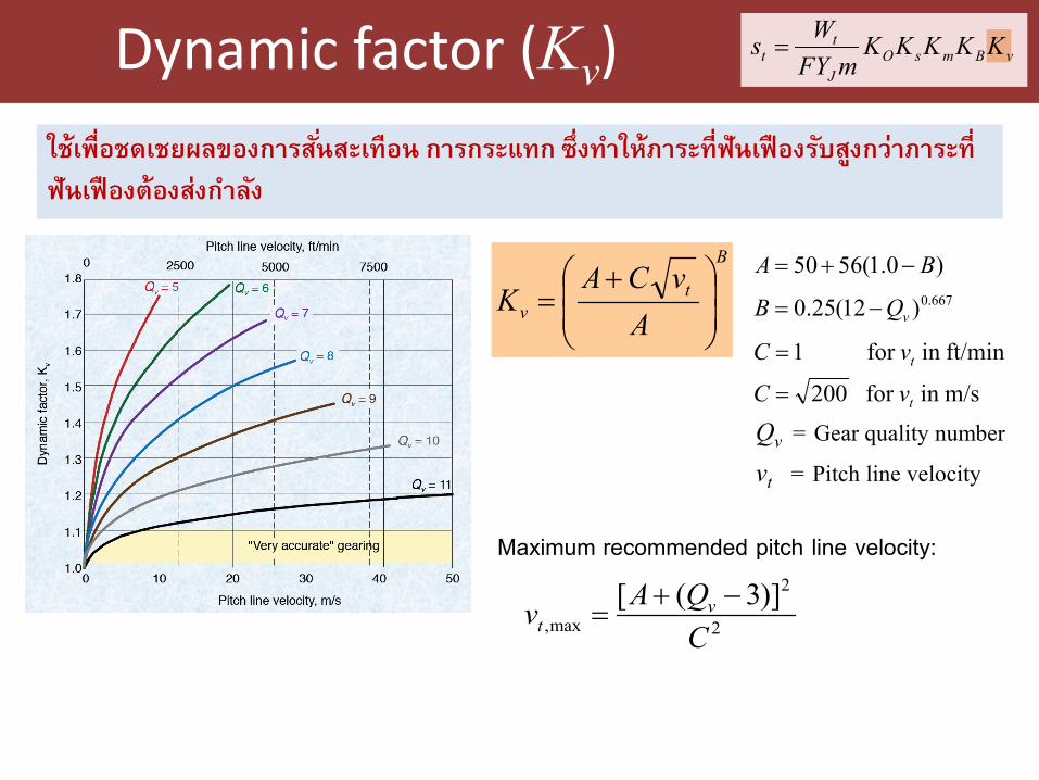
ใช้เพ่ือชดเชยผลของการสัน่สะเทือน การกระแทก ซ่ึงทาํให้ภาระท่ีฟันเฟืองรบัสงูกว่าภาระท่ี
ฟันเฟืองต้องส่งกาํลงั
B
tv A
vCAK
+=
)0.1(5650 BA −+=667.0)12(25.0 vQB −=
m/sin for 200
ft/minin for 1
t
t
vC
vC
=
=
Qv = Gear quality number
vt = Pitch line velocity
Maximum recommended pitch line velocity:
2
2
max,)]3([
CQAv v
t−+
=
Selection of material (bending stress)
vBmsOJ
tt KKKKK
mFYWs =
R
Natat KSF
Yss⋅
=′<
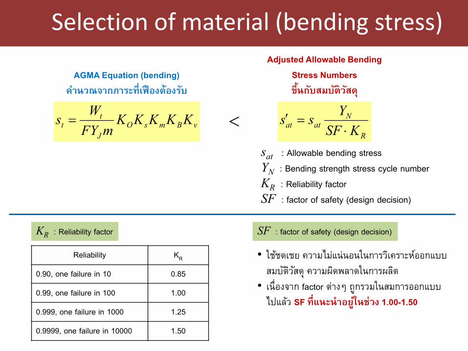
AGMA Equation (bending)
คาํนวณจากภาระท่ีเฟืองต้องรบั
Adjusted Allowable Bending
Stress Numbers
ขึ้นกบัสมบติัวสัด ุ
sat : Allowable bending stress
YN : Bending strength stress cycle number
KR : Reliability factor
SF : factor of safety (design decision)
KR : Reliability factor
Reliability KR
0.90, one failure in 10 0.85
0.99, one failure in 100 1.00
0.999, one failure in 1000 1.25
0.9999, one failure in 10000 1.50
SF : factor of safety (design decision)
• ใชช้ดเชย ความไมแ่น่นอนในการวเิคราะหอ์อกแบบ
สมบตัวิสัดุ ความผดิพลาดในการผลติ
• เนื่องจาก factor ต่างๆ ถูกรวมในสมการออกแบบ
ไปแลว้ SF ท่ีแนะนําอยู่ในช่วง 1.00-1.50
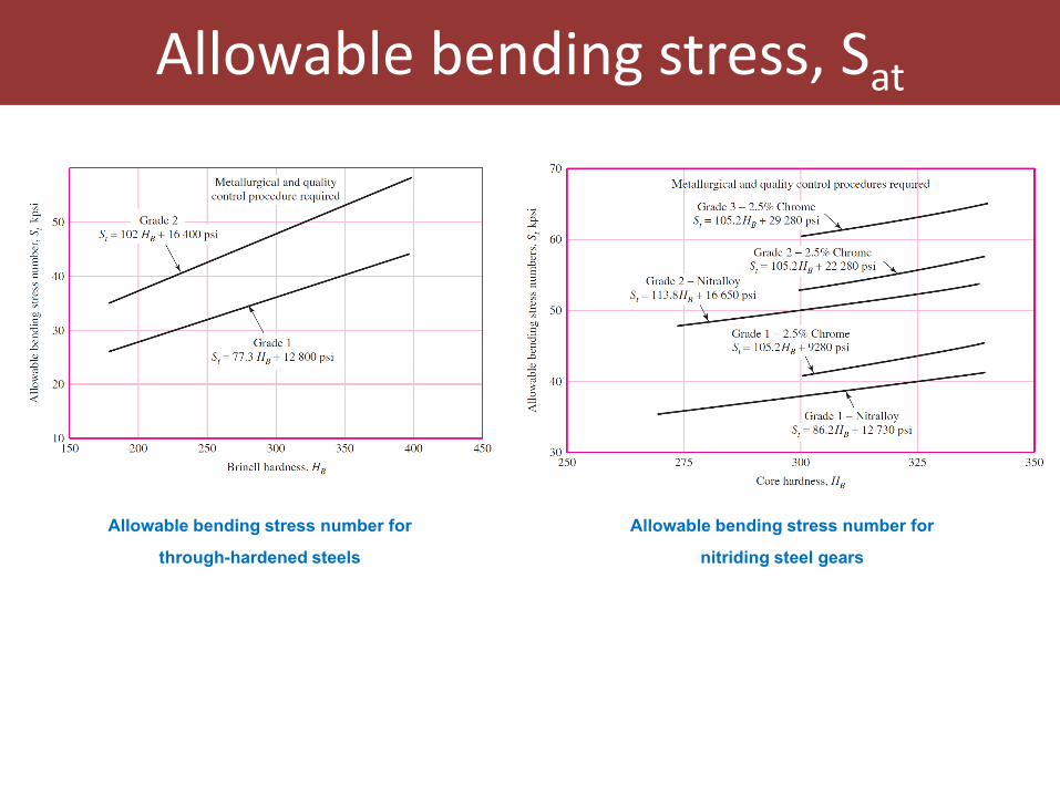
Allowable bending stress, Sat
Allowable bending stress number for
through-hardened steels
Allowable bending stress number for
nitriding steel gears
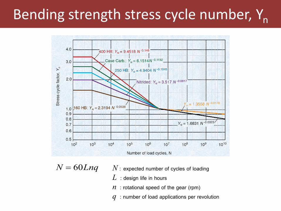
Bending strength stress cycle number, Yn
LnqN 60= N : expected number of cycles of loading
L : design life in hours
n : rotational speed of the gear (rpm)
q : number of load applications per revolution
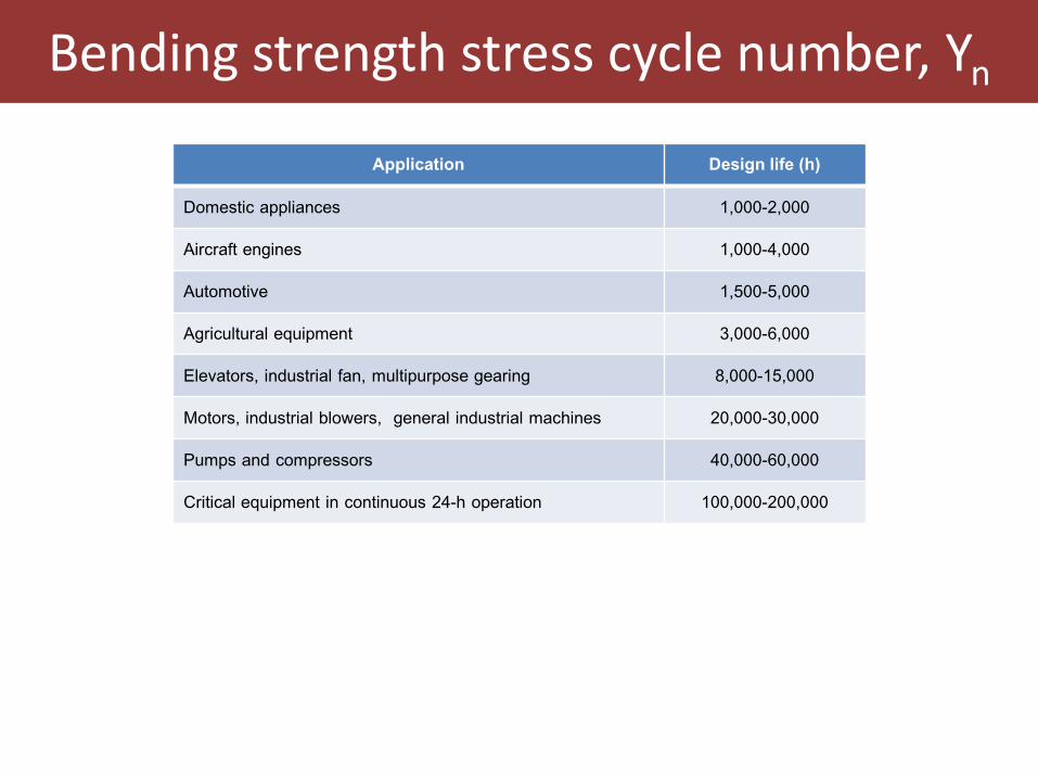
Bending strength stress cycle number, Yn
Application Design life (h)
Domestic appliances 1,000-2,000
Aircraft engines 1,000-4,000
Automotive 1,500-5,000
Agricultural equipment 3,000-6,000
Elevators, industrial fan, multipurpose gearing 8,000-15,000
Motors, industrial blowers, general industrial machines 20,000-30,000
Pumps and compressors 40,000-60,000
Critical equipment in continuous 24-h operation 100,000-200,000
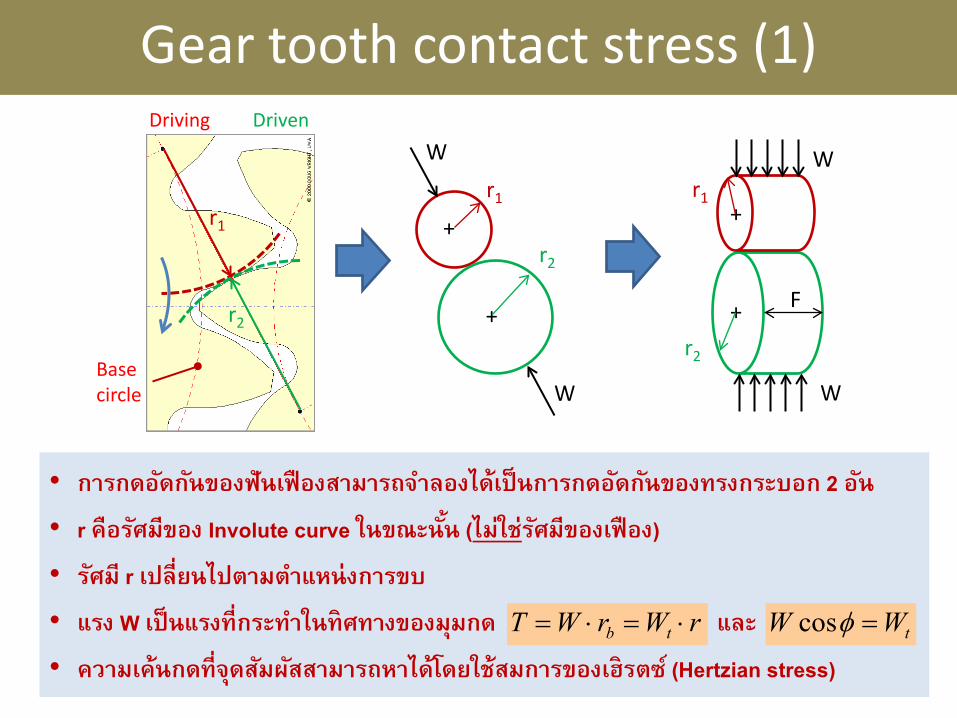
Gear tooth contact stress (1)
r1
r2
Driving Driven
r1
r2
W
W
+
+
+
+
r1
r2
W
W
F
• การกดอดักนัของฟันเฟืองสามารถจาํลองได้เป็นการกดอดักนัของทรงกระบอก 2 อนั
• r คือรศัมีของ Involute curve ในขณะนัน้ (ไม่ใช่รศัมีของเฟือง)
• รศัมี r เปล่ียนไปตามตาํแหน่งการขบ
• แรง W เป็นแรงท่ีกระทาํในทิศทางของมมุกด และ
• ความเค้นกดท่ีจดุสมัผสัสามารถหาได้โดยใช้สมการของเฮิรตซ ์(Hertzian stress)
Base circle
rWrWT tb ⋅=⋅= tWW =φcos
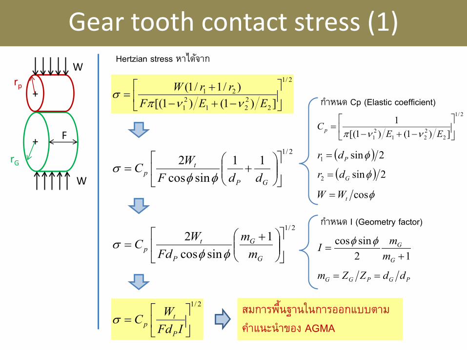
Gear tooth contact stress (1)
+
+
rp
rG
W
W
F
2/1
2221
21
21
])1()1([)/1/1(
−+−
+=
EEFrrWννπ
σ
Hertzian stress หาไดจ้าก
( ) 2sin2 φGdr =
( ) 2sin1 φPdr =
φcostWW =
กาํหนด Cp (Elastic coefficient) 2/1
2221
21 ])1()1([
1
−+−
=EE
Cp ννπ
2/111
sincos2
+=
GP
tp ddF
WCφφ
σ
2/11
sincos2
+=
G
G
P
tp m
mFd
WCφφ
σ
2/1
=
IFdWC
P
tpσ
12sincos
+=
G
G
mmI φφ
PGPGG ddZZm ==
กาํหนด I (Geometry factor)
สมการพืน้ฐานในการออกแบบตาม
คาํแนะนําของ AGMA
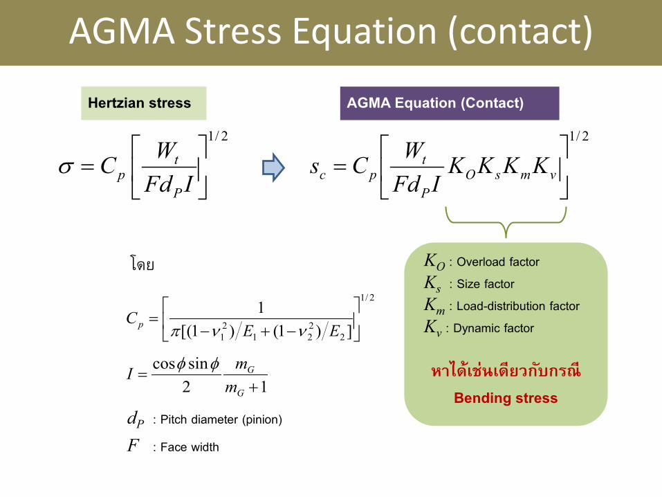
AGMA Stress Equation (contact)
2/1
=
IFdWC
P
tpσ
Hertzian stress AGMA Equation (Contact)
2/1
= vmsO
P
tpc KKKK
IFdWCs
KO : Overload factor
Ks : Size factor
Km : Load-distribution factor
Kv : Dynamic factor
หาได้เช่นเดียวกบักรณี
Bending stress 12
sincos+
=G
G
mmI φφ
2/1
2221
21 ])1()1([
1
−+−
=EE
Cp ννπ
โดย
dP : Pitch diameter (pinion)
F : Face width
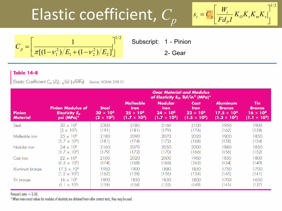
Elastic coefficient, Cp
2/1
= vmsO
P
tpc KKKK
IFdWCs
2/1
2221
21 ])1()1([
1
−+−
=EE
Cp ννπ1 - Pinion
2- Gear
Subscript:
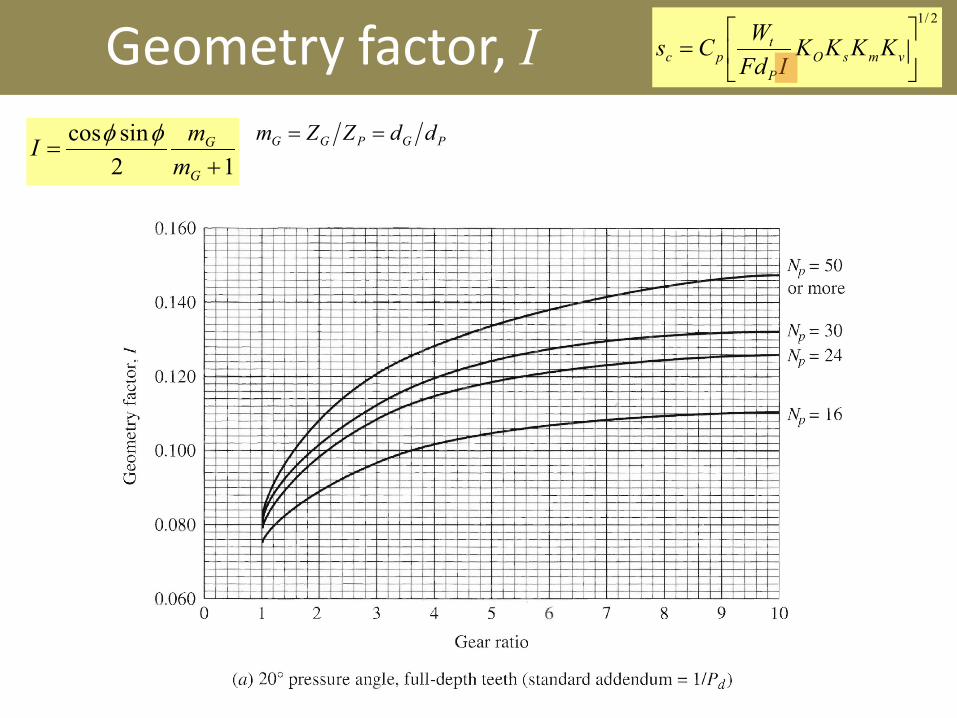
Geometry factor, I 2/1
= vmsO
P
tpc KKKK
IFdWCs
12sincos
+=
G
G
mmI φφ PGPGG ddZZm ==
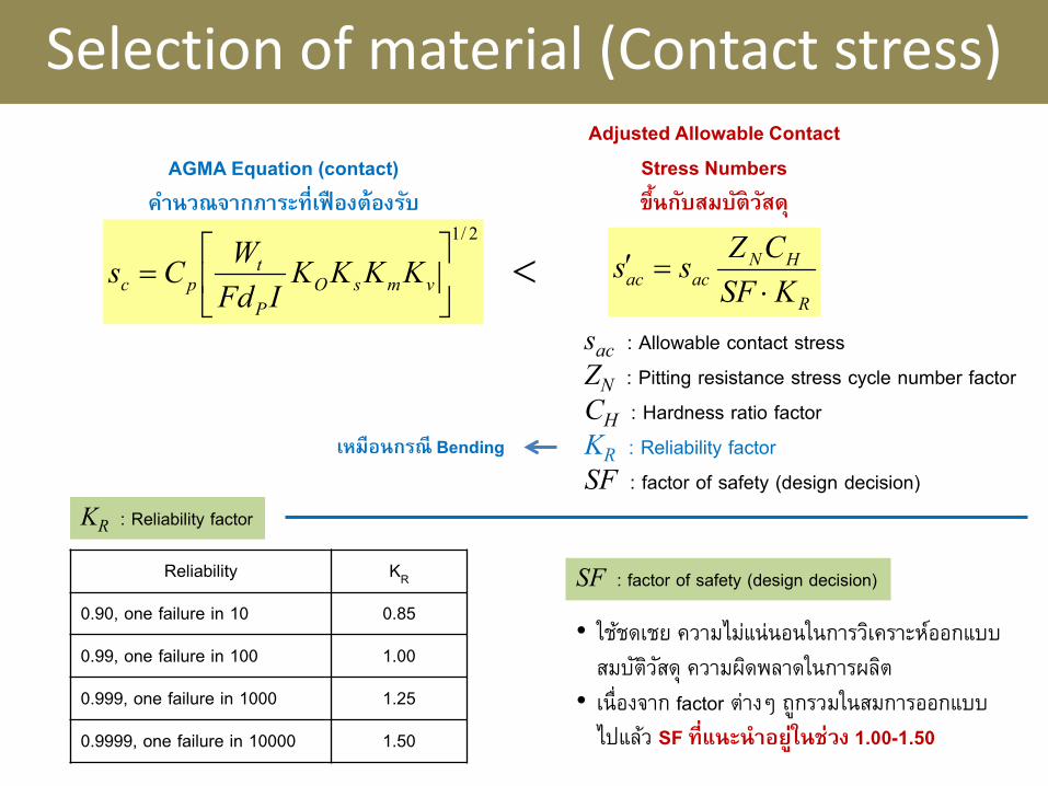
Selection of material (Contact stress)
R
HNacac KSF
CZss⋅
=′<
AGMA Equation (contact)
คาํนวณจากภาระท่ีเฟืองต้องรบั
Adjusted Allowable Contact
Stress Numbers
ขึ้นกบัสมบติัวสัด ุ
sac : Allowable contact stress
ZN : Pitting resistance stress cycle number factor
CH : Hardness ratio factor
KR : Reliability factor
SF : factor of safety (design decision)
KR : Reliability factor
Reliability KR
0.90, one failure in 10 0.85
0.99, one failure in 100 1.00
0.999, one failure in 1000 1.25
0.9999, one failure in 10000 1.50
SF : factor of safety (design decision)
• ใชช้ดเชย ความไมแ่น่นอนในการวเิคราะหอ์อกแบบ
สมบตัวิสัดุ ความผดิพลาดในการผลติ
• เนื่องจาก factor ต่างๆ ถูกรวมในสมการออกแบบ
ไปแลว้ SF ท่ีแนะนําอยู่ในช่วง 1.00-1.50
2/1
= vmsO
P
tpc KKKK
IFdWCs
เหมือนกรณี Bending
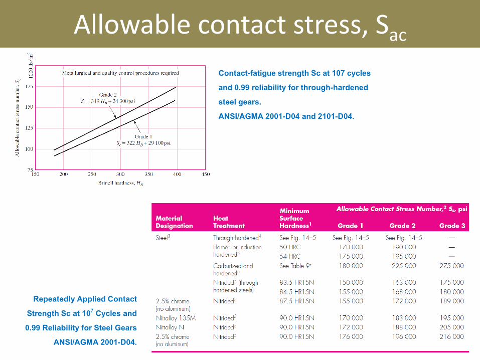
Allowable contact stress, Sac
Repeatedly Applied Contact
Strength Sc at 107 Cycles and
0.99 Reliability for Steel Gears
ANSI/AGMA 2001-D04.
Contact-fatigue strength Sc at 107 cycles
and 0.99 reliability for through-hardened
steel gears.
ANSI/AGMA 2001-D04 and 2101-D04.
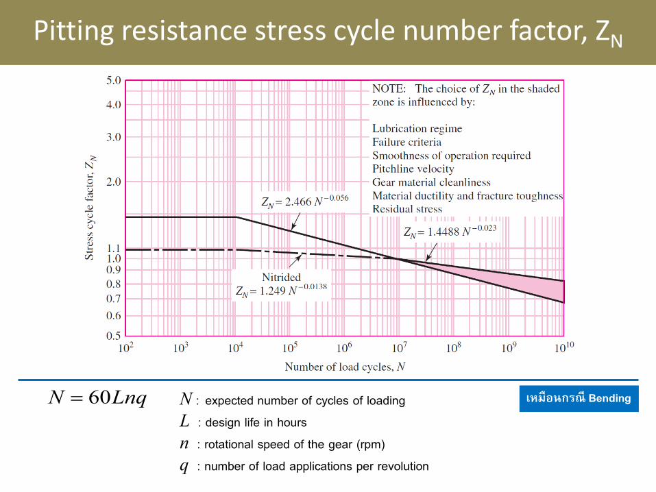
Pitting resistance stress cycle number factor, ZN
LnqN 60= N : expected number of cycles of loading
L : design life in hours
n : rotational speed of the gear (rpm)
q : number of load applications per revolution
เหมือนกรณี Bending
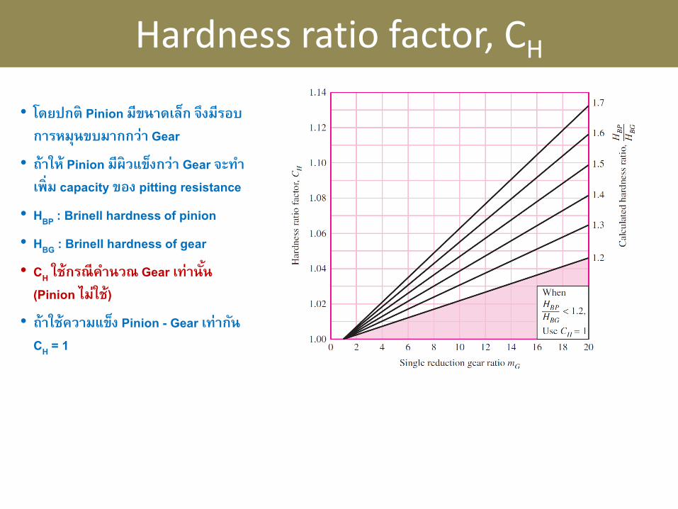
Hardness ratio factor, CH
• โดยปกติ Pinion มีขนาดเลก็ จึงมีรอบ
การหมุนขบมากกว่า Gear
• ถ้าให้ Pinion มีผิวแขง็กว่า Gear จะทาํ
เพ่ิม capacity ของ pitting resistance
• HBP : Brinell hardness of pinion
• HBG : Brinell hardness of gear
• CH ใช้กรณีคาํนวณ Gear เท่านัน้
(Pinion ไม่ใช้)
• ถ้าใช้ความแขง็ Pinion - Gear เท่ากนั
CH = 1
Design Guidelines
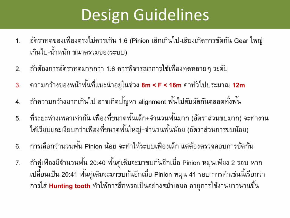
1. อตัราทดของเฟืองตรงไมค่วรเกนิ 1:6 (Pinion เลก็เกนิไป-เสีย่งเกดิการขดักนั Gear ใหญ่
เกนิไป-น้ําหนกั ขนาดรวมของระบบ)
2. ถา้ตอ้งการอตัราทดมากกวา่ 1:6 ควรพจิารณาการใชเ้ฟืองทดหลายๆ ระดบั
3. ความกวา้งของหน้าฟนัทีแ่นะนําอยูใ่นชว่ง 8m < F < 16m คา่ทัว่ไปประมาณ 12m
4. ถา้ความกวา้งมากเกนิไป อาจเกดิปญัหา alignment ฟนัไมส่มัผสักนัตลอดทัง้ฟนั
5. ทีร่ะยะหา่งเพลาเทา่กนั เฟืองทีข่นาดฟนัเลก็+จาํนวนฟนัมาก (อตัราสว่นขบมาก) จะทาํงาน
ไดเ้รยีบและเงยีบกวา่เฟืองทีข่นาดฟนัใหญ่+จาํนวนฟนัน้อย (อตัราสว่นการขบน้อย)
6. การเลอืกจาํนวนฟนั Pinion น้อย จะทาํใหร้ะบบเฟืองเลก็ แต่ตอ้งตรวจสอบการขดักนั
7. ถา้คูเ่ฟืองมจีาํนวนฟนั 20:40 ฟนัคูเ่ดมิจะมาขบกนัอกีเมือ่ Pinion หมนุเพยีง 2 รอบ หาก
เปลีย่นเป็น 20:41 ฟนัคูเ่ดมิจะมาขบกนัอกีเมือ่ Pinion หมนุ 41 รอบ การทาํเชน่น้ีเรยีกวา่
การใส ่Hunting tooth ทาํใหก้ารสกึหรอเป็นอยา่งสมํ่าเสมอ อายุการใชง้านยาวนานขึน้
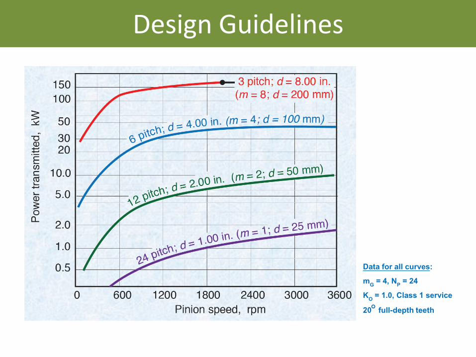
Design Guidelines
Data for all curves:
mG = 4, NP = 24
KO = 1.0, Class 1 service
20° full-depth teeth
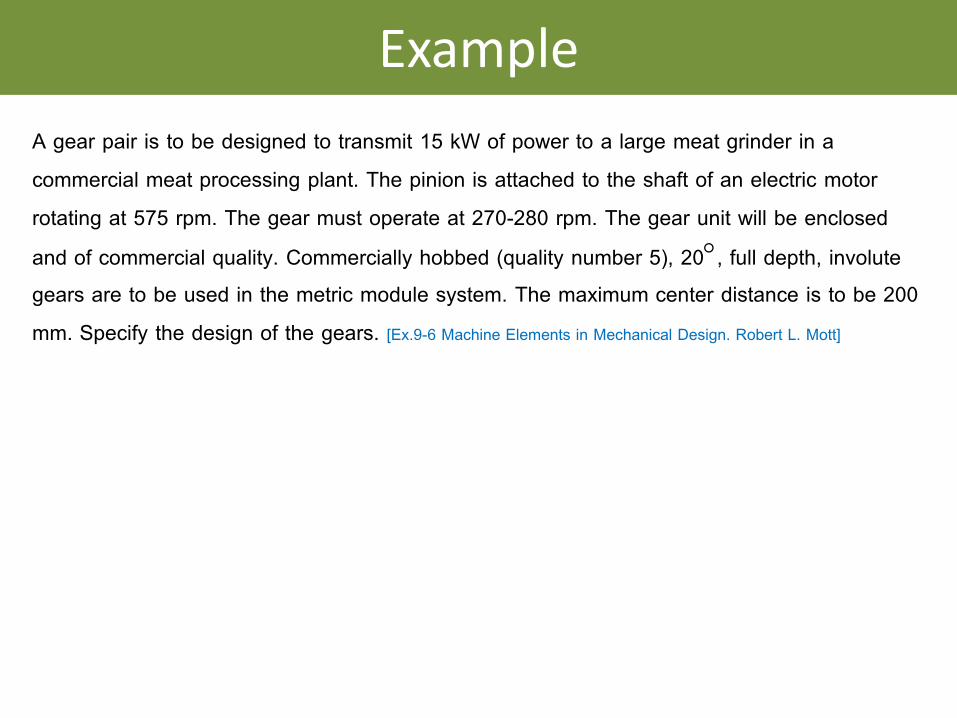
Example
A gear pair is to be designed to transmit 15 kW of power to a large meat grinder in a
commercial meat processing plant. The pinion is attached to the shaft of an electric motor
rotating at 575 rpm. The gear must operate at 270-280 rpm. The gear unit will be enclosed
and of commercial quality. Commercially hobbed (quality number 5), 20°, full depth, involute gears are to be used in the metric module system. The maximum center distance is to be 200
mm. Specify the design of the gears. [Ex.9-6 Machine Elements in Mechanical Design. Robert L. Mott]


![[1] involuteΣ(Spur and Helical Gear Design) 1.3 Software ...Eng).pdf · [1] involuteΣ(Spur and Helical Gear Design) 1 t Fig..1.1 Calculation Result Screen 1.1 Introduction involute](https://img.pdfslide.tips/doc/110x75/5a7894b47f8b9a7b698d1836/1-involutespur-and-helical-gear-design-13-software-engpdf1-involutespur.jpg)
![1.3 Basic rack, accuracy, strength [1] involuteΣiii(spur ...En_1]involuteΣⅲ(Spur and Helical) .pdf · 1 Basic rack setup 1.3 2 Dimension ... Gear strength calculation has several](https://img.pdfslide.tips/doc/110x75/5b869de97f8b9ad1318d57da/13-basic-rack-accuracy-strength-1-involuteiiispur-en1involutespur.jpg)


![[1] involuteΣiii(spur and helical gear design system)Spur...1 [1] involuteΣiii(spur and helical gear design system) 図1.1 involuteΣiii(spur and helical) 1.1 概要 involuteΣⅲ(spur](https://img.pdfslide.tips/doc/110x75/5ae0683d7f8b9a97518d2bd7/1-involuteiiispur-and-helical-gear-design-system-spur1-1-involuteiiispur.jpg)

![日本機械学会 2012 年度年次大会 [2012.9.9 12] Copyright ...shutingli/S111016.pdfKey Words: Gear, Spur Gear, Mesh Stiffness, Contact Analysis, Machining Errors, Tooth Modification](https://img.pdfslide.tips/doc/110x75/6119fe41d39e1375f442924a/oe-2012-201299-12-copyright-shutingli.jpg)