Embed Size (px)
Citation preview
Transportation of Micromachined Structures by Biomolecular Linear Motors
Ryuji Yokokawa*, Shoji Takeuchi*, Takahide Kon**, Reiko Ohkura**, Masaki Edamatsu**, Kazuo Sutoh**, and Hiroyuki Fujita*
*CIRMM/IIS, The University of Tokyo **Graduate School of Arts and Sciences, The University of Tokyo
4-6-1 Komaba, Meguro, Tokyo, 153-8505 Japan Telephone: +81-3-5452-6277, Fax: +81-3-5452-6250, E-mail: [email protected]
ABSTRACT
We have demonstrated a novel micro/nano transportation system using the adenosine triphosphate (ATP)-driven biomolecular motors. Two kinds of linear biomolecular motor systems, microtubule- kinesin [1] and actin- myosin [2], are investigated as driving mechanisms in the system. The rail molecules, microtubules, and actin are patterned on a glass substrate using a regular soft lithography technique with poly(dimethyl siloxane) (PDMS). A few µm order micromachined structure coated with the motor molecules was transported along the rail molecules.
INTRODUCTION
MEMS technology has been matured to produce many commercial products since its birth over ten years ago. Today many application-specific MEMS fields have emerged such as Bio-, RF- and Optical-MEMS. Bio-MEMS, in particular µTAS, has attracted large interest for the past few years. One of the advantages of µTAS is that the amount of chemical for analysis and reaction can be small. Reduction in chemical reaction chamber sizes has been the major way to decrease the amount of chemical solutions. If the concentration of target molecules in the sample is very low as is the case of environmental monitoring or some medical diagnosis, this strategy is obviously limited. Capturing the target molecules by immobilized chemicals that have specific affinity to the target gives an answer to the problem.
For this reason, bead-based assay in µTAS has been intensively studied [3]. Multi molecular analysis can be achieved by using beads with different molecular absorbents and by treating each
bead with different reactants. Several methods have been applied such as dielectrophoresis [4] magnetic field [5] and laser optical tweezer [6] to handle micro objects. These methods, however, have difficulties in handling one object, and the laser may damage biological targets. Here we propose the biomolecular motor system for the nano-scale particle handling in µTAS. Combining the biomolecular motor and conventional MEMS produces a novel hybrid system such as the nano-particle transportation system.
The biomolecular motors are driven by ATP or H+ gradient to drive in an aqueous condition (Table 1). Almost all actuation mechanisms of MEMS, however, depend on electrical or/and mechanical energy sources such as electrostatic, electromagnetic, thermal, and pneumatic energies. Compared with these conventional energy sources, ATP and H+ gradient are more compatible with the aqueous environment such as in µTAS.
Another advantage is that the biomolecular motors are real nano-scale actuators, which are categorized into linear motors and rotary motors as shown in Table 1. Even though the actuation part in MEMS has been minimized thanks to the progress of fabrication techniques, their energy still depends on an external energy source which is larger than the actuator size. The nano-size biomolecular motors can be utilized as a driving force in MEMS/NEMS actuators.
In order to realize such a hybrid system, we focused on biomolecular linear motors [7]. Linear motor systems are generally composed of rail molecules and motor molecules as shown in Table1 and Fig. 1. For example, myosin and kinesin move on their own rail molecules of actin and microtubule; the direction of motion is determined by the polarity of rail molecules. The gliding assay of rail molecules
Table 1: Biomolecular motors
Motor system Type Rail Motor Moving direction
Energy source Vital function
Actin Myosin [2] ± Kinesin [1] + Linear
motor Microtubule Dynein – ATP Gliding movement,
Intracellular transport
Counterclockwise ATP Active transport of H+ F1-ATPase [8]
Clockwise H+ gradient ATP synthesis Rotary motor
Flagellum Counterclockwise/clockwise H+ gradient Propulsive force
0-7803-7744-3/03/$17.00 ©2003 IEEE 8
(3) Piranha oxidization and chemical wash out using centrifugations
(4) Structures are collected in a biochemical buffer
(1) Laser beam lithography and Si etching by DRIE
SOI 2 µmSiO2 1 µm
Si 500 µm
(2) Dicing of the wafer and HF release in a centrifugation tube
HFCentrifugation tube
15000 rpm, 10 minStructures (400 nm~2 µm)
Buffer
Structures to be released
Myosin/Kinesin (motor)
Moving direction
Actin/Microtubule (rail)
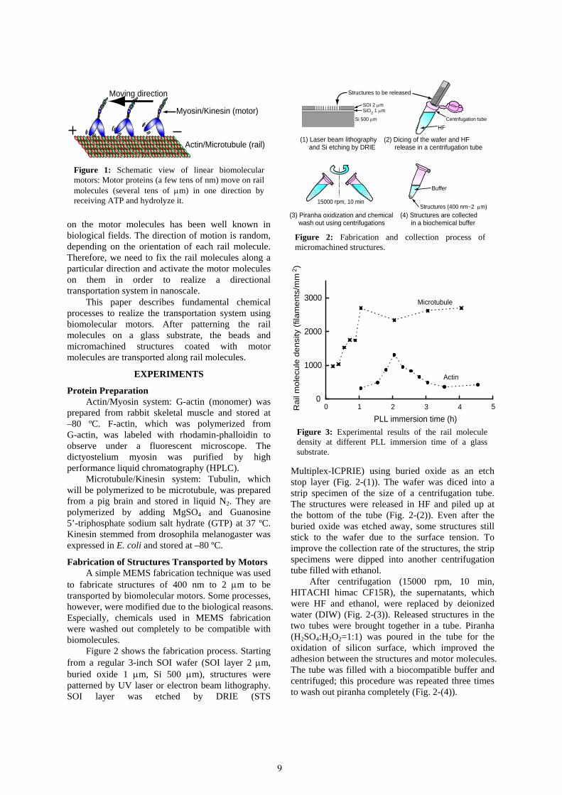
Figure 1: Schematic view of linear biomolecularmotors: Motor proteins (a few tens of nm) move on rail molecules (several tens of µm) in one direction byreceiving ATP and hydrolyze it.
on the motor molecules has been well known in biological fields. The direction of motion is random, depending on the orientation of each rail molecule. Therefore, we need to fix the rail molecules along a particular direction and activate the motor molecules on them in order to realize a directional transportation system in nanoscale.
Figure 2: Fabrication and collection process of micromachined structures.
Microtubule
Actin
PLL immersion time (h)
Rai
l mol
ecul
e de
nsity
(fila
men
ts/m
m2 )
0
1000
2000
3000
0 1 2 3 4 5
This paper describes fundamental chemical processes to realize the transportation system using biomolecular motors. After patterning the rail molecules on a glass substrate, the beads and micromachined structures coated with motor molecules are transported along rail molecules.
EXPERIMENTS
Protein Preparation Actin/Myosin system: G-actin (monomer) was
prepared from rabbit skeletal muscle and stored at –80 ºC. F-actin, which was polymerized from G-actin, was labeled with rhodamin-phalloidin to observe under a fluorescent microscope. The dictyostelium myosin was purified by high performance liquid chromatography (HPLC).
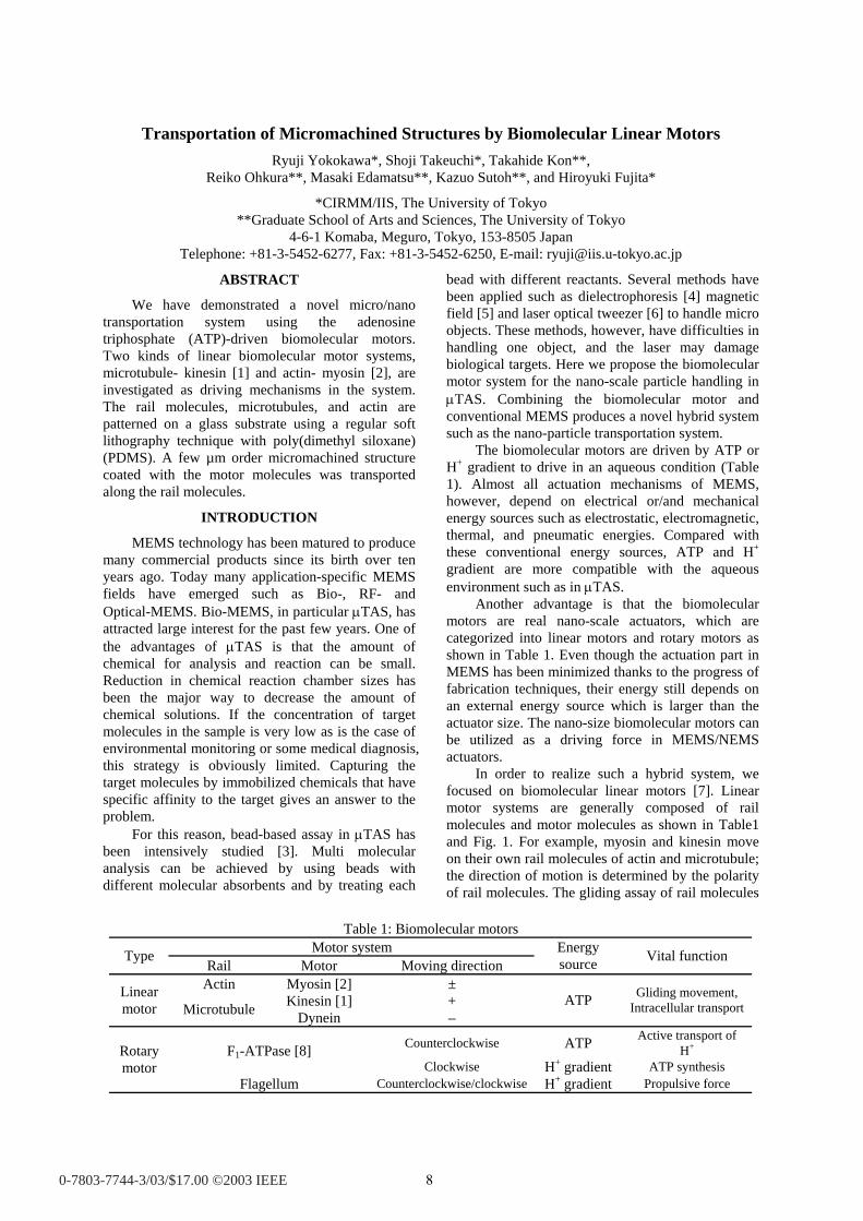
Figure 3: Experimental results of the rail molecule density at different PLL immersion time of a glass substrate.
Microtubule/Kinesin system: Tubulin, which will be polymerized to be microtubule, was prepared from a pig brain and stored in liquid N2. They are polymerized by adding MgSO4 and Guanosine 5’-triphosphate sodium salt hydrate (GTP) at 37 ºC. Kinesin stemmed from drosophila melanogaster was expressed in E. coli and stored at –80 ºC.
Fabrication of Structures Transported by Motors A simple MEMS fabrication technique was used
to fabricate structures of 400 nm to 2 µm to be transported by biomolecular motors. Some processes, however, were modified due to the biological reasons. Especially, chemicals used in MEMS fabrication were washed out completely to be compatible with biomolecules.
Figure 2 shows the fabrication process. Starting from a regular 3-inch SOI wafer (SOI layer 2 µm, buried oxide 1 µm, Si 500 µm), structures were patterned by UV laser or electron beam lithography. SOI layer was etched by DRIE (STS
Multiplex-ICPRIE) using buried oxide as an etch stop layer (Fig. 2-(1)). The wafer was diced into a strip specimen of the size of a centrifugation tube. The structures were released in HF and piled up at the bottom of the tube (Fig. 2-(2)). Even after the buried oxide was etched away, some structures still stick to the wafer due to the surface tension. To improve the collection rate of the structures, the strip specimens were dipped into another centrifugation tube filled with ethanol.
After centrifugation (15000 rpm, 10 min, HITACHI himac CF15R), the supernatants, which were HF and ethanol, were replaced by deionized water (DIW) (Fig. 2-(3)). Released structures in the two tubes were brought together in a tube. Piranha (H2SO4:H2O2=1:1) was poured in the tube for the oxidation of silicon surface, which improved the adhesion between the structures and motor molecules. The tube was filled with a biocompatible buffer and centrifuged; this procedure was repeated three times to wash out piranha completely (Fig. 2-(4)).
9
Kinesin
MicrotubleGlass substrate
Beador
structure
PLL Beador
structure
Attachment of Rail Molecules Compared with the biological gliding assay, the
rail molecules need to be fixed on the substrate for the artificial transportation system. The condition to attach the rail molecules on a glass substrate was optimized. Since rail molecules in general do not have an affinity to the glass surface, an amino acid (Poly-L-Lysine: 0.01 % PLL, Sigma, P4707) was used as a binding material between a glass and the rail proteins. The relationship between the microtubule/actin densities vs. the PLL immersion time is plotted in Fig. 3. The density of microtubules
saturated after 1 hour and kept that density of 3.0×10³ filaments/mm2. The density of actin, on the other hand, was maximized at 2 hours with the density of 1.4×10³ filaments/mm2. The motor molecules are well known to attach on the negatively charged surface such as a glass. This is why the surface of all fabricated structures was negatively charged by dipping into piranha (Fig. 2-(3)).
Patterning of Rail Molecules The patterning technique of the rail molecules
was established to activate the motor molecules in a desired area. PLL was patterned on the area only where we needed to activate motor molecules.
The process is shown in Fig. 4. A PDMS mold, which had channels of 10 - 100 µm in width and 50
Figure 4: PLL patterning technique using a PDMS mold.
Figure 5: Images of patterned microtubules and actin.
Figure 6: Schimatic view of that the kinesin coated bead is transported on microtubule.
Kinesin beads on microtubules
10 µm
Coating
(3) Buffer and microtubule/actin insertion
(1) PLL insertion to channels using a syringe with a rubber connection
(2) Wash & peel off
Make a flow cell
Spacer
Cover glass
Patterned PLLPLL
PDMS channel
Rubber connection
Glass plate
12
5ml
34 Glass area
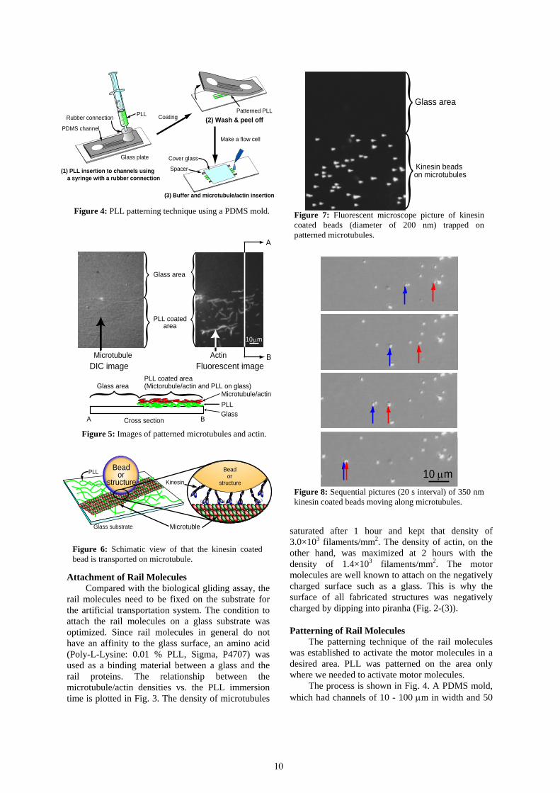
Figure 7: Fluorescent microscope picture of kinesin coated beads (diameter of 200 nm) trapped on patterned microtubules. A
BMicrotubuleDIC image Fluorescent image
Glass area
PLL coatedarea
Actin
Microtubule/actinPLLGlass
A B
Glass area
Cross section
PLL coated area(Mictorubule/actin and PLL on glass)
10µm
Figure 8: Sequential pictures (20 s interval) of 350 nm kinesin coated beads moving along microtubules.
10
µm in depth, was placed on a glass substrate (Fig. 4-(1)). Using a rubber connection, PLL was injected into the channels by applying pressure with a syringe. Extra PLL was washed out by a buffer and the PDMS mold was removed (Fig. 4-(2)). The flow cell was fabricated by placing spacers and a cover glass on the PLL-patterned area (Fig. 4-(3)). Rail molecules were introduced and attached on the PLL-coated area only inside of the flow cell. Successful patterning of microtubules and actin filaments was clearly observed by a differential interference contrast (DIC) microscope and a fluorescent microscope (Olympus, IX70), respectively (Fig. 5).
Transportation System In order to prove the ability of biomolecular
motors to transport artificial structures, we chose the
microtubule-kinesin system. As a first step, bead assay was performed. Carboxylate-modified beads (320 nm diameter, Bangs Lab.) coated with kinesin molecules (Fig. 6) were introduced and trapped on the microtubules patterned area (Fig. 7). They were transported along microtubules at the average speed of 470 nm/s (Fig. 8).
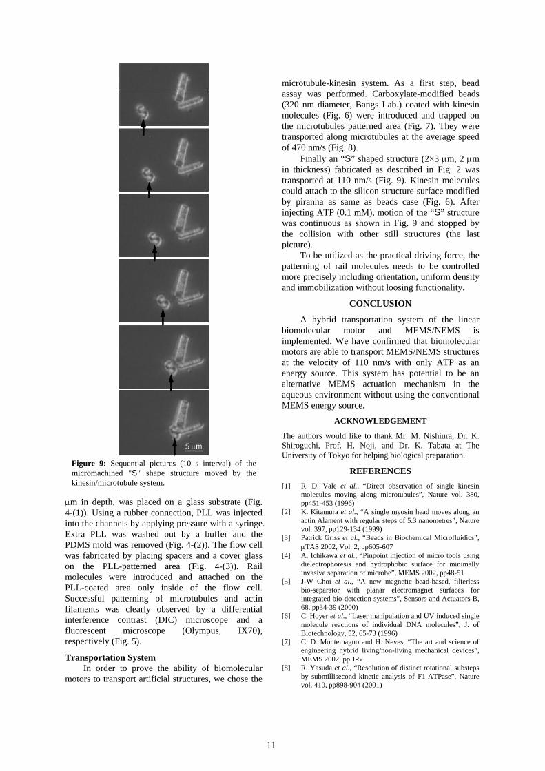
Finally an “S” shaped structure (2×3 µm, 2 µm in thickness) fabricated as described in Fig. 2 was transported at 110 nm/s (Fig. 9). Kinesin molecules could attach to the silicon structure surface modified by piranha as same as beads case (Fig. 6). After injecting ATP (0.1 mM), motion of the “S” structure was continuous as shown in Fig. 9 and stopped by the collision with other still structures (the last picture).
To be utilized as the practical driving force, the patterning of rail molecules needs to be controlled more precisely including orientation, uniform density and immobilization without loosing functionality.
5 µm
CONCLUSION
A hybrid transportation system of the linear biomolecular motor and MEMS/NEMS is implemented. We have confirmed that biomolecular motors are able to transport MEMS/NEMS structures at the velocity of 110 nm/s with only ATP as an energy source. This system has potential to be an alternative MEMS actuation mechanism in the aqueous environment without using the conventional MEMS energy source.
ACKNOWLEDGEMENT
The authors would like to thank Mr. M. Nishiura, Dr. K. Shiroguchi, Prof. H. Noji, and Dr. K. Tabata at The University of Tokyo for helping biological preparation.
Figure 9: Sequential pictures (10 s interval) of themicromachined "S" shape structure moved by thekinesin/microtubule system.
REFERENCES
[1] R. D. Vale et al., “Direct observation of single kinesin molecules moving along microtubules”, Nature vol. 380, pp451-453 (1996)
[2] K. Kitamura et al., “A single myosin head moves along an actin Alament with regular steps of 5.3 nanometres”, Nature vol. 397, pp129-134 (1999)
[3] Patrick Griss et al., “Beads in Biochemical Microfluidics”, µTAS 2002, Vol. 2, pp605-607
[4] A. Ichikawa et al., “Pinpoint injection of micro tools using dielectrophoresis and hydrophobic surface for minimally invasive separation of microbe”, MEMS 2002, pp48-51
[5] J-W Choi et al., “A new magnetic bead-based, filterless bio-separator with planar electromagnet surfaces for integrated bio-detection systems”, Sensors and Actuators B, 68, pp34-39 (2000)
[6] C. Hoyer et al., “Laser manipulation and UV induced single molecule reactions of individual DNA molecules”, J. of Biotechnology, 52, 65-73 (1996)
[7] C. D. Montemagno and H. Neves, “The art and science of engineering hybrid living/non-living mechanical devices”, MEMS 2002, pp.1-5
[8] R. Yasuda et al., “Resolution of distinct rotational substeps by submillisecond kinetic analysis of F1-ATPase”, Nature vol. 410, pp898-904 (2001)
11