Embed Size (px)
Citation preview
Topic 1.4 LevelTopic 1.4 Level-- 11EEB5223/EAB4223 Industrial Automation & Control Systems
Dr. Rosdiazli IbrahimDepartment of Electrical & Electronics EngineeringUniversiti Teknologi Petronas22.03.027Email: [email protected]: 05-368 7821
Industrial Instrumentation and Measurements
Liquid-LevelMeasurements
Topic 1.4 LevelTopic 1.4 Level-- 22EEB5223/EAB4223 Industrial Automation & Control Systems
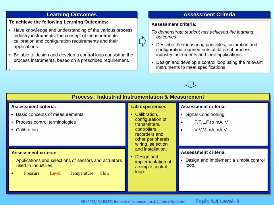
Learning OutcomesLearning OutcomesLearning OutcomesTo achieve the following Learning Outcomes:
• Have knowledge and understanding of the various process industry instruments, the concept of measurements, calibration and configuration requirements and their applications.
• Be able to design and develop a control loop consisting the process instruments, based on a prescribed requirement.
.
Assessment CriteriaAssessment CriteriaAssessment Criteria
Assessment criteria:To demonstrate student has achieved the learning
outcomes
• Describe the measuring principles, calibration and configuration requirements of different process industry instruments and their applications.
• Design and develop a control loop using the relevant instruments to meet specifications
Assessment criteria:• Basic concepts of measurements
• Process control terminologies
• Calibration
Lab experiences• Calibration,
configuration of transmitters, controllers, recorders and other peripherals, wiring, selection and installation.
• Design and implementation of a simple control loop.
Assessment criteria:• Signal Conditioning
• P,T,L,F to mA, V
• V-V,V-mA,mA-V
Assessment criteria:• Applications and selections of sensors and actuators
used in industries
• Pressure Level Temperature Flow
Assessment criteria:• Design and implement a simple control
loop.
Process , Industrial Instrumentation & MeasurementProcess , Industrial Instrumentation & MeasurementProcess , Industrial Instrumentation & Measurement
Topic 1.4 LevelTopic 1.4 Level-- 33EEB5223/EAB4223 Industrial Automation & Control Systems
LEVEL MEASUREMENTSPurpose:To monitor and measure quantitatively the liquid content in vessels , reservoirs and tanks
Type of device used - depends on the accuracy, repeatability, range & instrumentation needed
Topic 1.4 LevelTopic 1.4 Level-- 44EEB5223/EAB4223 Industrial Automation & Control Systems
Measurement can be made directly, or can Measurement can be made directly, or can be inferred (indirectly).be inferred (indirectly).
• Example of direct measurement sensors:o Conductivity electrodes, eg capacitive sensor.
o Ultrasonic
• Example of indirect measurement sensors:
o Static pressure method
Topic 1.4 LevelTopic 1.4 Level-- 55EEB5223/EAB4223 Industrial Automation & Control Systems
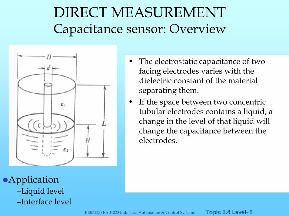
DIRECT MEASUREMENTCapacitance sensor: Overview
• The electrostatic capacitance of two facing electrodes varies with the dielectric constant of the material separating them.
• If the space between two concentric tubular electrodes contains a liquid, a change in the level of that liquid will change the capacitance between the electrodes.
Application–Liquid level–Interface level
Topic 1.4 LevelTopic 1.4 Level-- 66EEB5223/EAB4223 Industrial Automation & Control Systems
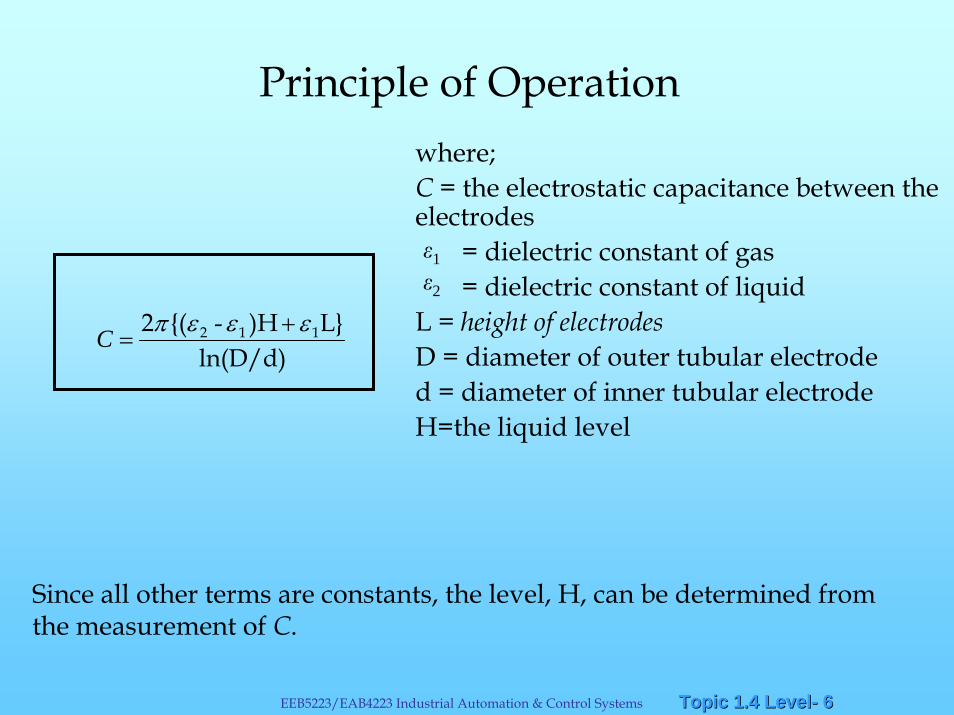
Principle of Operationwhere; C = the electrostatic capacitance between the electrodes
= dielectric constant of gas= dielectric constant of liquid
L = height of electrodesD = diameter of outer tubular electroded = diameter of inner tubular electrodeH=the liquid level
ln(D/d)L})H-{(2 112 εεεπ +
=C
1
2
Since all other terms are constants, the level, H, can be determined from the measurement of C.
Topic 1.4 LevelTopic 1.4 Level-- 77EEB5223/EAB4223 Industrial Automation & Control Systems
Advantages of capacitance sensor• No moving parts• Elements are easily cleaned• Safe elements (explosion-proof instrument)
Limitations• Measurement error may occur
– if a change of temperature changes dielectric constant– if viscous conducting liquids coat the sensing element– due to air bubbles in liquid or foam on top of liquid
Topic 1.4 LevelTopic 1.4 Level-- 88EEB5223/EAB4223 Industrial Automation & Control Systems
DIRECT MEASUREMENTUltrasonic sensor: Overview
• Based on high-frequency sound waves produced by AC signal
• The chosen operating frequency should corresponds to the resonant frequency of transmitter and receiver
• Transmitter - Generates ultrasonic pulse, measure time taken for echo to return
• Receiver - receives reflected signal
Application• Measure level of liquid (miscible and non-miscible liquid)
• Determine position of liquid / sludge interface
Topic 1.4 LevelTopic 1.4 Level-- 99EEB5223/EAB4223 Industrial Automation & Control Systems
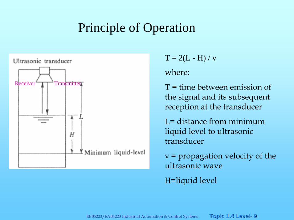
Principle of Operation
H
T = 2(L - H) / v
where:
T = time between emission of the signal and its subsequent reception at the transducer
L= distance from minimum liquid level to ultrasonic transducer
v = propagation velocity of the ultrasonic wave
H=liquid level
TransmitterReceiver
Topic 1.4 LevelTopic 1.4 Level-- 1010EEB5223/EAB4223 Industrial Automation & Control Systems
Advantage• Able to measure level without physical contact
• No moving parts, so inspection and maintenance are easy.
• Reliability of reading unaffected by changes in the composition, density & moisture content of process fluid
• Small and light, installation is easy.
Limitation
• Due to dispersion & absorption, reflected signal weaken
Topic 1.4 LevelTopic 1.4 Level-- 1111EEB5223/EAB4223 Industrial Automation & Control Systems
INDIRECT MEASUREMENTStatic Pressure Measurement of Level
•A convenient means of measuring liquid level, where there is a considerable change in level.
•Employs conventional industrial instruments which is actuated bychanges in hydrostatic pressure head of the liquid as the level changes.
•This head is the “weight” of liquid above a reference level or datum line. Head is often expressed in terms of pressure or level height.
Summary
Topic 1.4 LevelTopic 1.4 Level-- 1212EEB5223/EAB4223 Industrial Automation & Control Systems
EEB 5223 Industrial Automation & Control Systems
Static Pressure Measurement of LevelSummary
•Measurement of pressure due to liquid head can be translated to level height above the datum line by the following basic relationship:
h=P/ρg
where h=height or level
P=pressure due to hydrostatic head
ρ=density of the liquid
g=acceleration due to gravity
•For the readings to be accurate the density have to be constant.
•The accuracy will be affected for e.g., temperature variations is sufficient to cause changes in the density of the liquid.
Topic 1.4 LevelTopic 1.4 Level-- 1313EEB5223/EAB4223 Industrial Automation & Control Systems
The use of DP transmitter for liquid-level measurement:
• The DP transmitter must be positioned below the minimum liquid level.
• Corrections must be made for changes in the density of the liquid.
• If there is a pulsating motion in the liquid, the output of the transmitter will be unstable.
• The tapping tube should be as straight as possible so as not to trap air.
Summary
Topic 1.4 LevelTopic 1.4 Level-- 1414EEB5223/EAB4223 Industrial Automation & Control Systems
Inferential Level MeasurementThis technique obtains a level indication indirectly by monitoring the pressure exerted by the height of the liquid in the vessel.
The pressure at the base of a vessel containing liquid is directly proportional to the height of the liquid in the vessel. This is termed hydrostatic pressure. As the level in the vessel rises, the pressure exerted by the liquid at the base of the vessel will increase linearly.
Mathematically,
P=S.H ,
where
P=Pressure (Pa), S=Weight density of the liquid (N/m3)= g
H=Height of liquid column (m), =Density (kg/m3)
g=acceleration due to gravity (9.81 m/s2)
Topic 1.4 LevelTopic 1.4 Level-- 1515EEB5223/EAB4223 Industrial Automation & Control Systems
Inferential Level Measurement
DP capsules are the most commonly used devices to measure the pressure at the base of a tank.
The level of liquid inside a tank can be determined from the pressure reading if the weight density of the liquid is constant.
Use a pressure capsule that has a sensitivity range that closelymatches the anticipated pressure of the measured liquid.
Topic 1.4 LevelTopic 1.4 Level-- 1616EEB5223/EAB4223 Industrial Automation & Control Systems
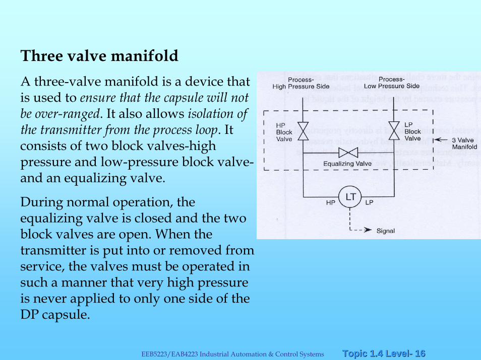
Three valve manifoldA three-valve manifold is a device that is used to ensure that the capsule will not be over-ranged. It also allows isolation of the transmitter from the process loop. It consists of two block valves-high pressure and low-pressure block valve-and an equalizing valve.
During normal operation, the equalizing valve is closed and the two block valves are open. When the transmitter is put into or removed from service, the valves must be operated in such a manner that very high pressure is never applied to only one side of the DP capsule.
Topic 1.4 LevelTopic 1.4 Level-- 1717EEB5223/EAB4223 Industrial Automation & Control Systems
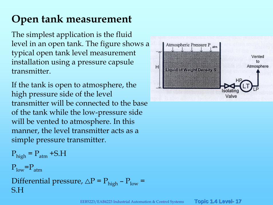
Open tank measurementThe simplest application is the fluid level in an open tank. The figure shows a typical open tank level measurement installation using a pressure capsule transmitter.
If the tank is open to atmosphere, the high pressure side of the level transmitter will be connected to the base of the tank while the low-pressure side will be vented to atmosphere. In this manner, the level transmitter acts as a simple pressure transmitter.
Phigh = Patm +S.H
Plow=Patm
Differential pressure, <P = Phigh – Plow = S.H
Topic 1.4 LevelTopic 1.4 Level-- 1818EEB5223/EAB4223 Industrial Automation & Control Systems
Closed tank MeasurementShould the tank be closed and a gas or vapour exists on top of the liquid, the gas pressure must be compensated for. A change in the gas pressure will cause a change in transmitter output. Moreover, the pressure exerted by the gas phase may be so high that the hydrostatic pressure of the liquid column becomes insignificant.
For example, the measured hydrostatic head in a boiler may be only three meters (30kPa) or so, whereas the steam pressure is typically 5 MPa.
Compensation can be achieved by applying the gas pressure to both high and low-pressure sides of the level transmitter. This cover gas pressure is thus used as a back pressure (or reference pressure) on the LP side of the DP cell. One can immediately see the need for the three-valve manifold to protect the DP cell against these pressures.
Topic 1.4 LevelTopic 1.4 Level-- 1919EEB5223/EAB4223 Industrial Automation & Control Systems
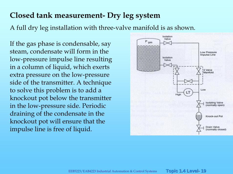
Closed tank measurement- Dry leg systemA full dry leg installation with three-valve manifold is as shown.
If the gas phase is condensable, say steam, condensate will form in the low-pressure impulse line resulting in a column of liquid, which exerts extra pressure on the low-pressure side of the transmitter. A technique to solve this problem is to add a knockout pot below the transmitter in the low-pressure side. Periodic draining of the condensate in the knockout pot will ensure that the impulse line is free of liquid.
Topic 1.4 LevelTopic 1.4 Level-- 2020EEB5223/EAB4223 Industrial Automation & Control Systems
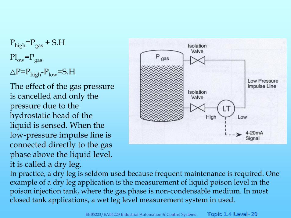
Phigh=Pgas + S.H
Plow=Pgas
<P=Phigh-Plow=S.H
The effect of the gas pressure is cancelled and only the pressure due to the hydrostatic head of the liquid is sensed. When the low-pressure impulse line is connected directly to the gas phase above the liquid level, it is called a dry leg.In practice, a dry leg is seldom used because frequent maintenance is required. One example of a dry leg application is the measurement of liquid poison level in the poison injection tank, where the gas phase is non-condensable medium. In most closed tank applications, a wet leg level measurement system in used.
Topic 1.4 LevelTopic 1.4 Level-- 2121EEB5223/EAB4223 Industrial Automation & Control Systems
Closed tank measurement -Wet Leg System
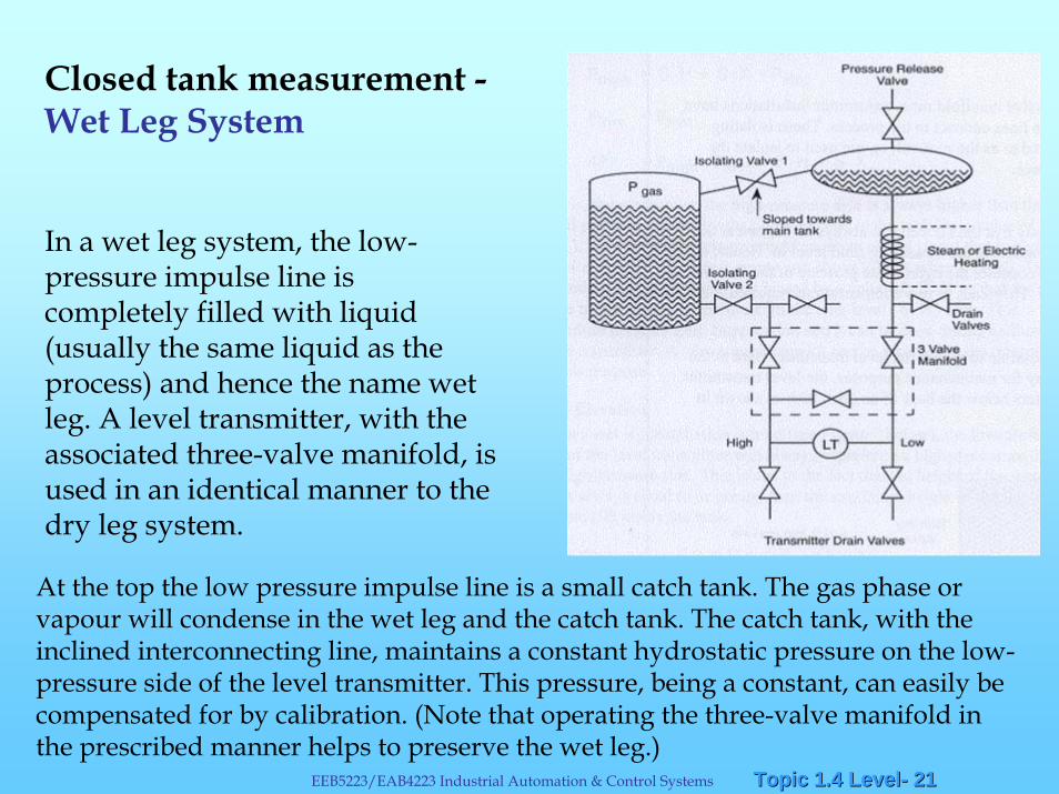
In a wet leg system, the low-pressure impulse line is completely filled with liquid (usually the same liquid as the process) and hence the name wet leg. A level transmitter, with the associated three-valve manifold, is used in an identical manner to the dry leg system.
At the top the low pressure impulse line is a small catch tank. The gas phase or vapour will condense in the wet leg and the catch tank. The catch tank, with the inclined interconnecting line, maintains a constant hydrostatic pressure on the low-pressure side of the level transmitter. This pressure, being a constant, can easily be compensated for by calibration. (Note that operating the three-valve manifold in the prescribed manner helps to preserve the wet leg.)
Topic 1.4 LevelTopic 1.4 Level-- 2222EEB5223/EAB4223 Industrial Automation & Control Systems
If the tank is located outdoors, trace heating of the wet leg might be necessary to prevent it from freezing. Steam lines or an electric heating element can be wound around the wet leg to keep to keep the temperature of the condensate above its freezing point.
Note the two sets of drain valves. The transmitter drain valves would be used to drain (bleed) the transmitter only. The two drain valves located immediately above the three-valve manifold are used for impulse and wet leg draining and filling.
In addition to the three-valve manifold most transmitter installations have valves where the impulse lines connect to the process. These isolating valves, sometimes referred to as the root valves, are used to isolate the transmitter for maintenance.
Wet Leg System continue…
Topic 1.4 LevelTopic 1.4 Level-- 2323EEB5223/EAB4223 Industrial Automation & Control Systems
Level Compensation
It would be idealistic to say that the DP cell can always be located at the exact bottom of the vessel we are measuring fluid level in.
Hence, the `measuring system’ has to consider the hydrostatic pressure of the fluid in the sensing lines themselves.
This leads to two compensations required.
Topic 1.4 LevelTopic 1.4 Level-- 2424EEB5223/EAB4223 Industrial Automation & Control Systems
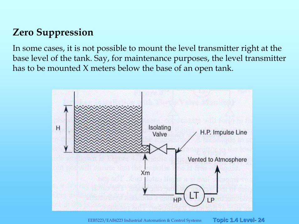
Zero SuppressionIn some cases, it is not possible to mount the level transmitter right at the base level of the tank. Say, for maintenance purposes, the level transmitter has to be mounted X meters below the base of an open tank.
Topic 1.4 LevelTopic 1.4 Level-- 2525EEB5223/EAB4223 Industrial Automation & Control Systems
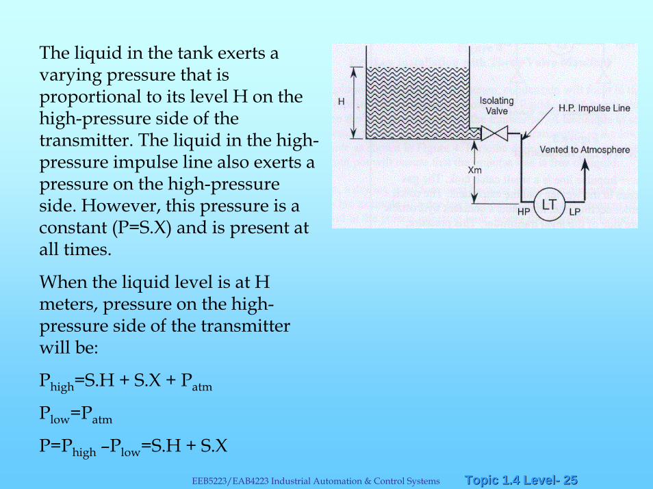
The liquid in the tank exerts a varying pressure that is proportional to its level H on the high-pressure side of the transmitter. The liquid in the high-pressure impulse line also exerts a pressure on the high-pressure side. However, this pressure is a constant (P=S.X) and is present at all times.
When the liquid level is at H meters, pressure on the high-pressure side of the transmitter will be:
Phigh=S.H + S.X + Patm
Plow=Patm
P=Phigh –Plow=S.H + S.X
Topic 1.4 LevelTopic 1.4 Level-- 2626EEB5223/EAB4223 Industrial Automation & Control Systems
That is, the pressure on the high-pressure side is always higher than the actual pressure exerted by the liquid column in the tank ( by a value of S.X).
This constant pressure would cause an output signal that is higher than 4 mA when the tank is empty and above 20 mAwhen it is full. The transmitter has to be negatively biased by a value of -S.X, only.
This procedure is called Zero Suppression and it can be done during calibration of the transmitter.
Topic 1.4 LevelTopic 1.4 Level-- 2727EEB5223/EAB4223 Industrial Automation & Control Systems
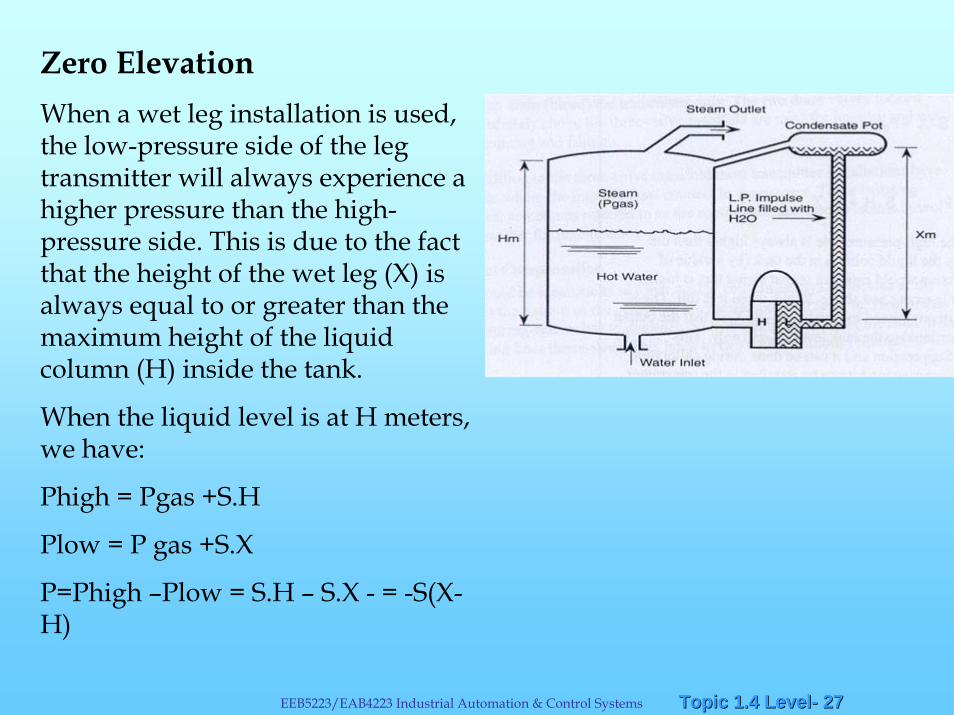
Zero ElevationWhen a wet leg installation is used, the low-pressure side of the leg transmitter will always experience a higher pressure than the high-pressure side. This is due to the fact that the height of the wet leg (X) is always equal to or greater than the maximum height of the liquid column (H) inside the tank.
When the liquid level is at H meters, we have:
Phigh = Pgas +S.H
Plow = P gas +S.X
P=Phigh –Plow = S.H – S.X - = -S(X-H)
Topic 1.4 LevelTopic 1.4 Level-- 2828EEB5223/EAB4223 Industrial Automation & Control Systems
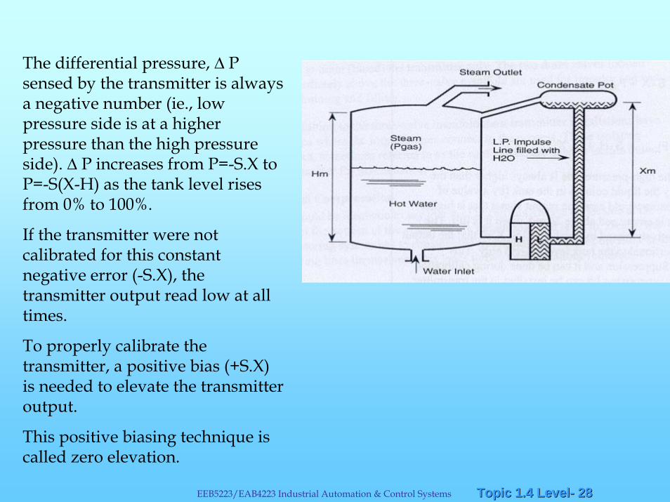
The differential pressure, P sensed by the transmitter is always a negative number (ie., low pressure side is at a higher pressure than the high pressure side). P increases from P=-S.X to P=-S(X-H) as the tank level rises from 0% to 100%.
If the transmitter were not calibrated for this constant negative error (-S.X), the transmitter output read low at all times.
To properly calibrate the transmitter, a positive bias (+S.X) is needed to elevate the transmitter output.
This positive biasing technique is called zero elevation.
Topic 1.4 LevelTopic 1.4 Level-- 2929EEB5223/EAB4223 Industrial Automation & Control Systems
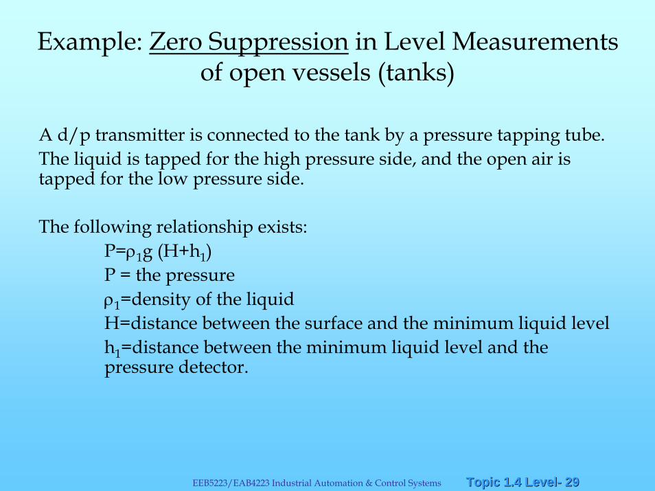
Example: Zero Suppression in Level Measurements of open vessels (tanks)
A d/p transmitter is connected to the tank by a pressure tapping tube.The liquid is tapped for the high pressure side, and the open air is tapped for the low pressure side.
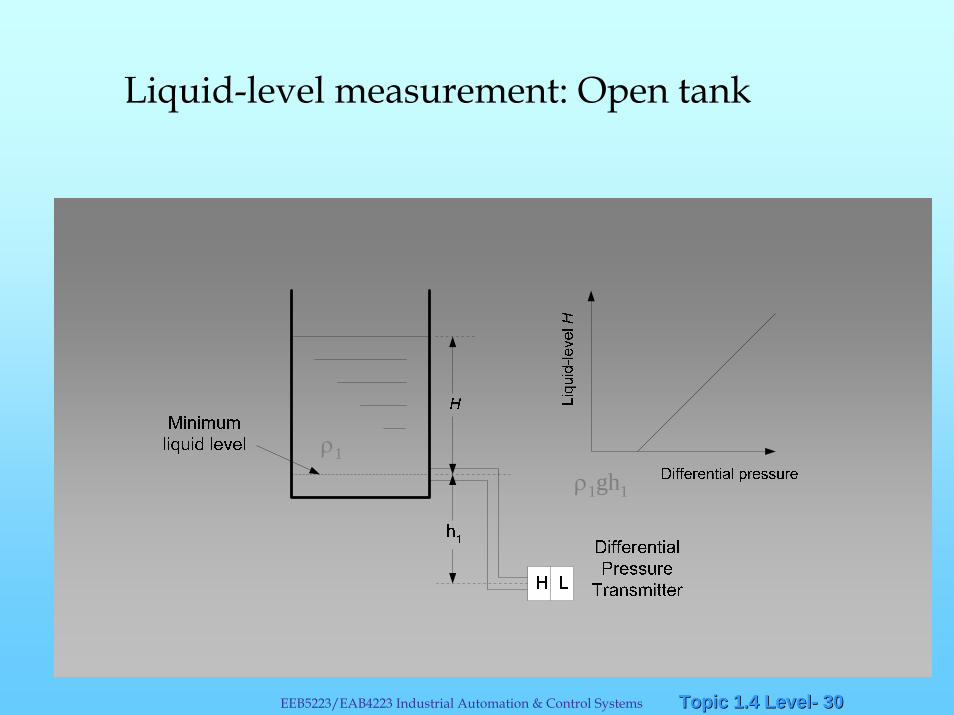
The following relationship exists:P=ρ1g (H+h1)P = the pressureρ1=density of the liquidH=distance between the surface and the minimum liquid levelh1=distance between the minimum liquid level and the pressure detector.
Topic 1.4 LevelTopic 1.4 Level-- 3030EEB5223/EAB4223 Industrial Automation & Control Systems
Liquid-level measurement: Open tank
ρ1gh1
ρ1
Topic 1.4 LevelTopic 1.4 Level-- 3131EEB5223/EAB4223 Industrial Automation & Control Systems
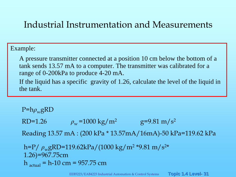
Example:A pressure transmitter connected at a position 10 cm below the bottom of a tank sends 13.57 mA to a computer. The transmitter was calibrated for a range of 0-200kPa to produce 4-20 mA. If the liquid has a specific gravity of 1.26, calculate the level of the liquid in the tank.
Industrial Instrumentation and Measurements
P=h wgRD
RD=1.26 w =1000 kg/m2 g=9.81 m/s2
Reading 13.57 mA : (200 kPa * 13.57mA/16mA)-50 kPa=119.62 kPa
h=P/ wgRD=119.62kPa/(1000 kg/m2 *9.81 m/s2* 1.26)=967.75cmh actual = h-10 cm = 957.75 cm
Topic 1.4 LevelTopic 1.4 Level-- 3232EEB5223/EAB4223 Industrial Automation & Control Systems
Example: Zero Elevation in Level Measurements of closed vessels (tanks)
A DP transmitter is connected to the closed tank: the low pressure tap is the pressure of the gas above the liquid in the upper part of the tank.
The pressure of the gas is also applied to the high pressure tap at the same time. Hence, when taking the pressure differential, it cancels out and so does not affect the transmitter output.
If condensation from the gas in the upper part of the tank collects inside the tapping tube, the low pressure tapping pressure in the tube will change and the output of the d/p transmitter will be affected. To avoid this, the condensation is collected in a drain pot.
Dry leg method
Topic 1.4 LevelTopic 1.4 Level-- 3333EEB5223/EAB4223 Industrial Automation & Control Systems
Liquid-level measurement: Closed tank – Dry Leg
H L
H
h1
Minimumliquid-level
Maximumliquid-level
Dryleg
Drainpot
Differential-pressuretransmitter
Liqu
id-le
vel H
Differential pressure
PG
ρ1
ρ1gh1
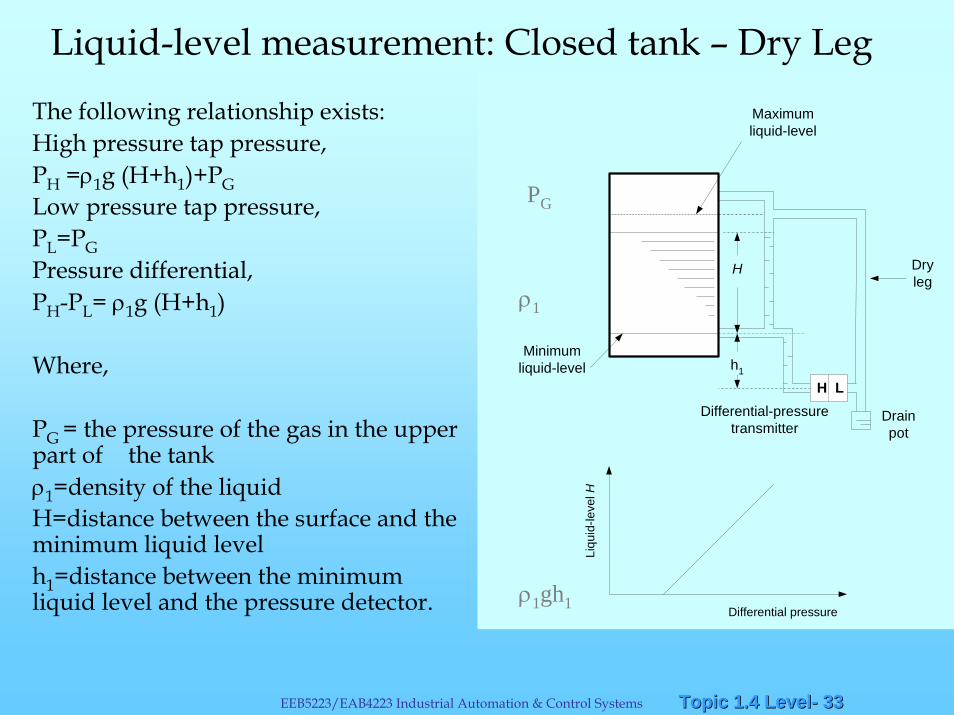
The following relationship exists:High pressure tap pressure, PH =ρ1g (H+h1)+PGLow pressure tap pressure, PL=PGPressure differential, PH-PL= ρ1g (H+h1)
Where,
PG = the pressure of the gas in the upper part of the tankρ1=density of the liquidH=distance between the surface and the minimum liquid levelh1=distance between the minimum liquid level and the pressure detector.
Topic 1.4 LevelTopic 1.4 Level-- 3434EEB5223/EAB4223 Industrial Automation & Control Systems
Example: Zero Elevation in Level Measurements of closed vessels (tanks) – Wet Leg
Wet leg method
Similarly, a d/p transmitter is connected to the closed tank: the low pressure tap is the pressure of the gas above the liquid in the upper part of the tank.
A relatively heavy liquid (high density) that does not easily evaporate to fill the tube. The pressure of the gas in the tank is then applied to the pressure detector through this liquid.
Topic 1.4 LevelTopic 1.4 Level-- 3535EEB5223/EAB4223 Industrial Automation & Control Systems
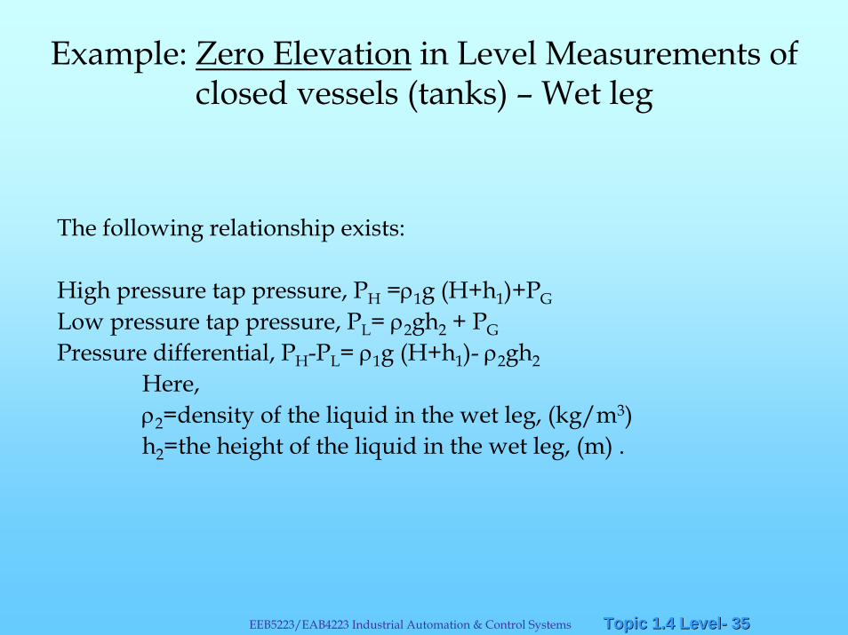
Example: Zero Elevation in Level Measurements of closed vessels (tanks) – Wet leg
The following relationship exists:
High pressure tap pressure, PH =ρ1g (H+h1)+PGLow pressure tap pressure, PL= ρ2gh2 + PGPressure differential, PH-PL= ρ1g (H+h1)- ρ2gh2
Here,ρ2=density of the liquid in the wet leg, (kg/m3)h2=the height of the liquid in the wet leg, (m) .
Topic 1.4 LevelTopic 1.4 Level-- 3636EEB5223/EAB4223 Industrial Automation & Control Systems
Liquid-level measurement: Closed tank-wet leg
H L
H
h1
Minimumliquid-level
Maximumliquid-level
Wetleg
Differential-pressuretransmitter
Liqu
id-le
vel H
Differential pressure
h2ρ1
PG
ρ1gh1- ρ2gh2
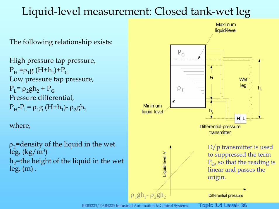
D/p transmitter is used to suppressed the term PG, so that the reading is linear and passes the origin.
The following relationship exists:
High pressure tap pressure, PH =ρ1g (H+h1)+PGLow pressure tap pressure, PL= ρ2gh2 + PGPressure differential, PH-PL= ρ1g (H+h1)- ρ2gh2
where,
ρ2=density of the liquid in the wet leg, (kg/m3)h2=the height of the liquid in the wet leg, (m) .
Topic 1.4 LevelTopic 1.4 Level-- 3737EEB5223/EAB4223 Industrial Automation & Control Systems
Bubbler level measurement system
If the process liquid contains suspended solids or is chemically corrosive or radioactive, it is desirable to prevent it from coming into direct contact with the level transmitter.
In these cases, a bubbler level measurement system, which utilize a purge gas , can be used.
Topic 1.4 LevelTopic 1.4 Level-- 3838EEB5223/EAB4223 Industrial Automation & Control Systems
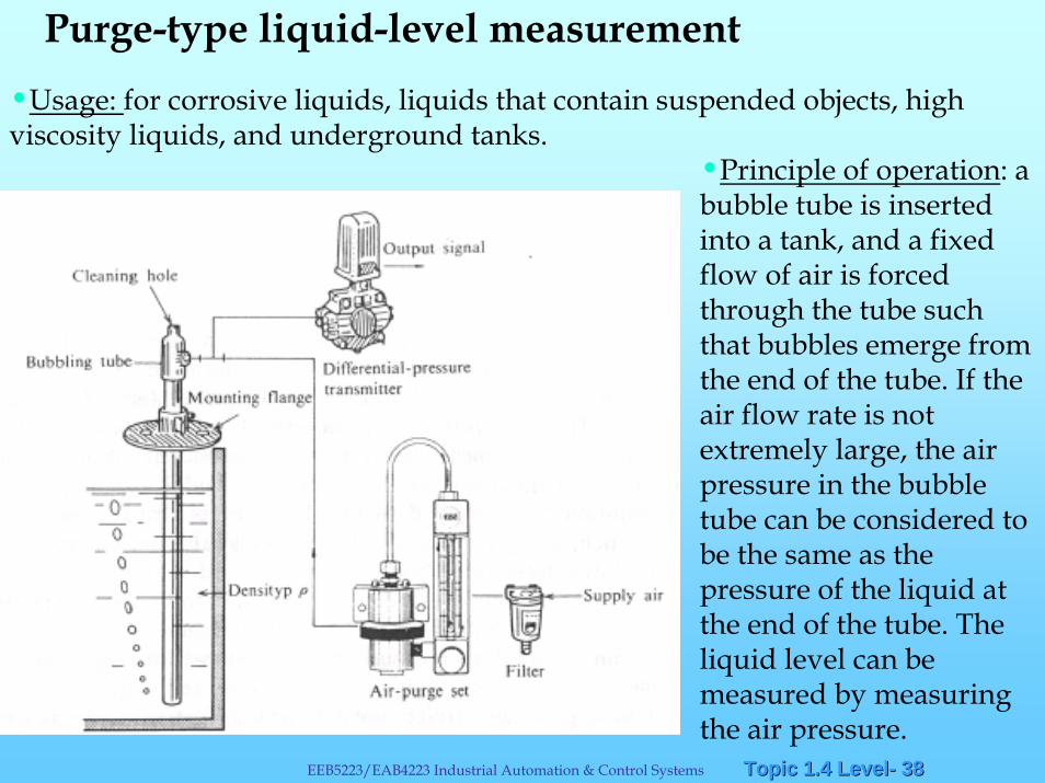
Purge-type liquid-level measurement•Usage: for corrosive liquids, liquids that contain suspended objects, high viscosity liquids, and underground tanks.
•Principle of operation: a bubble tube is inserted into a tank, and a fixed flow of air is forced through the tube such that bubbles emerge from the end of the tube. If the air flow rate is not extremely large, the air pressure in the bubble tube can be considered to be the same as the pressure of the liquid at the end of the tube. The liquid level can be measured by measuring the air pressure.
Topic 1.4 LevelTopic 1.4 Level-- 3939EEB5223/EAB4223 Industrial Automation & Control Systems
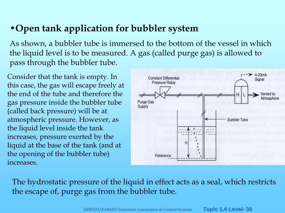
•Open tank application for bubbler systemAs shown, a bubbler tube is immersed to the bottom of the vessel in which the liquid level is to be measured. A gas (called purge gas) is allowed to pass through the bubbler tube.
Consider that the tank is empty. In this case, the gas will escape freely at the end of the tube and therefore the gas pressure inside the bubbler tube (called back pressure) will be at atmospheric pressure. However, as the liquid level inside the tank increases, pressure exerted by the liquid at the base of the tank (and at the opening of the bubbler tube) increases.
The hydrostatic pressure of the liquid in effect acts as a seal, which restricts the escape of, purge gas from the bubbler tube.
Topic 1.4 LevelTopic 1.4 Level-- 4040EEB5223/EAB4223 Industrial Automation & Control Systems
As a result, the gas pressure in the bubbler tube will continue to increase until it just balances the hydrostatic pressure (P=S.H) of the liquid. At this point the backpressure in the bubbler tube is exactly the same as the hydrostatic pressure of the liquid and it will remain constant until any changes in the liquid level occurs. Any excess supply will escape as bubbles through the liquid.
As the liquid level rises, the backpressure in the bubbler tube increases proportionally, since the density of the liquid is constant. A level transmitter (DP cell) can be used to monitor this backpressure. In an open tank installation, the bubbler tube is connected to the high-pressure side of the transmitter, while the low pressure side is vented to atmosphere. The output of the transmitter will be proportional to the tank level.
Topic 1.4 LevelTopic 1.4 Level-- 4141EEB5223/EAB4223 Industrial Automation & Control Systems
A constant differential pressure relay is often used in the purge gas line to ensure that constant bubbling action occurs at all tank levels. The relay maintains a constant flow rate of purge gas in the bubbler tube regardless of tank variations or supply fluctuations. This ensures that bubbling will occur to maximum tank level and the flow rate does not increase at low tank levelin such a way as to cause excessive disturbances at the surface of the liquid. Note that the bubbling action has to be continuous or the measurement signal will not be accurate.
An additional advantage of the bubbler system is that, since it measures only the backpressure of the purge gas, the exact location of the level transmitter is not important. The transmitter can be mounted some distance from the process.
Topic 1.4 LevelTopic 1.4 Level-- 4242EEB5223/EAB4223 Industrial Automation & Control Systems
• Closed tank application for bubbler system
If the bubbler system is to be applied to measure level in a closed tank, some pressure-regulating scheme must be provided for the gas space in the tank. Otherwise, the gas bubbling through the liquid will pressurize the gas space to a point where bubbler supply pressure cannot overcome the static pressure it acts against. The result would be no bubble flow and, therefore, inaccurate measurement signal. Also, as in the case of a closed tank inferential level measurement system, the low-pressure side of the level transmitter has to be connected to the gas space in order to compensate for the effect of gas pressure.
Topic 1.4 LevelTopic 1.4 Level-- 4343EEB5223/EAB4223 Industrial Automation & Control Systems
• Effect of temperature on level measurement
Level measurement systems that use DP as the sensing method are by their very nature affected by temperature and pressure.
H α P/ρΡ α 1/TH α T
For any given amount of liquid in a container, the pressure P exerted at the base will remain constant, but the height will vary directly with the temperature.
Topic 1.4 LevelTopic 1.4 Level-- 4444EEB5223/EAB4223 Industrial Automation & Control Systems
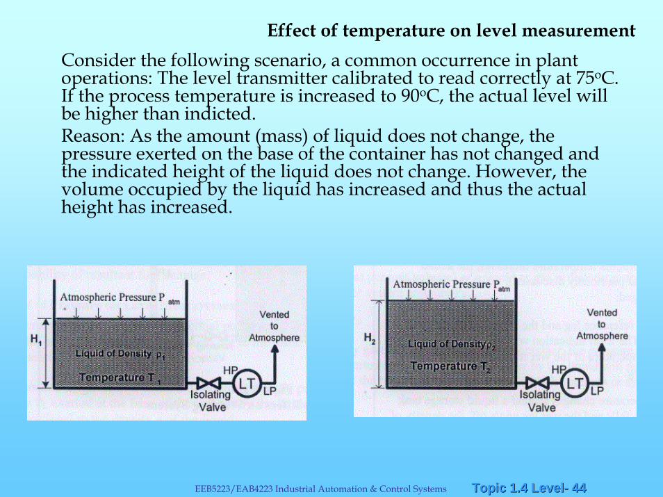
Consider the following scenario, a common occurrence in plant operations: The level transmitter calibrated to read correctly at 75oC. If the process temperature is increased to 90oC, the actual level will be higher than indicted. Reason: As the amount (mass) of liquid does not change, the pressure exerted on the base of the container has not changed and the indicated height of the liquid does not change. However, thevolume occupied by the liquid has increased and thus the actual height has increased.
Effect of temperature on level measurement
Topic 1.4 LevelTopic 1.4 Level-- 4545EEB5223/EAB4223 Industrial Automation & Control Systems
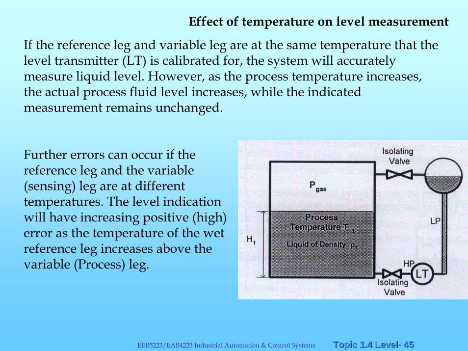
If the reference leg and variable leg are at the same temperature that the level transmitter (LT) is calibrated for, the system will accurately measure liquid level. However, as the process temperature increases, the actual process fluid level increases, while the indicated measurement remains unchanged.
Further errors can occur if the reference leg and the variable (sensing) leg are at different temperatures. The level indication will have increasing positive (high) error as the temperature of the wet reference leg increases above the variable (Process) leg.
Effect of temperature on level measurement
Topic 1.4 LevelTopic 1.4 Level-- 4646EEB5223/EAB4223 Industrial Automation & Control Systems
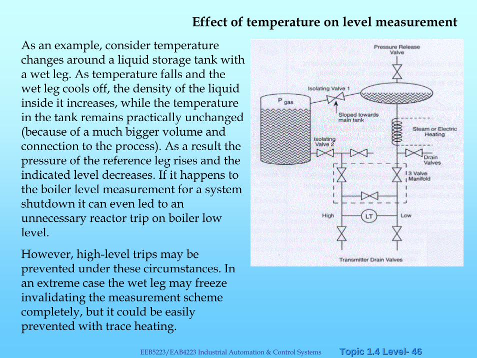
As an example, consider temperature changes around a liquid storage tank with a wet leg. As temperature falls and the wet leg cools off, the density of the liquid inside it increases, while the temperature in the tank remains practically unchanged (because of a much bigger volume and connection to the process). As a result the pressure of the reference leg rises and the indicated level decreases. If it happens to the boiler level measurement for a system shutdown it can even led to an unnecessary reactor trip on boiler low level.
However, high-level trips may be prevented under these circumstances. In an extreme case the wet leg may freeze invalidating the measurement scheme completely, but it could be easily prevented with trace heating.
Effect of temperature on level measurement
Topic 1.4 LevelTopic 1.4 Level-- 4747EEB5223/EAB4223 Industrial Automation & Control Systems
False high level indication can be caused by an increased wet leg temperature, gas or vapour bubbles or a drained wet leg.
A high measured tank level, with the real being dangerously low, may prevent the actuation of a safety system on a low value of the trip parameter.
The real level may even get sufficiently low to cause either the cavitationof the pumps that take suction from the tank or gas ingress into the pumps and result in gas locking and a reduced or no flow condition.
Effect of temperature on level measurement
Topic 1.4 LevelTopic 1.4 Level-- 4848EEB5223/EAB4223 Industrial Automation & Control Systems
• Effect of pressure on level measurement
Level measurement systems that use DP as the sensing method are by their very nature affected by temperature and pressure.
H α PL/ρρ α PSH α 1/PS
For any given amount of liquid in a container, the pressure PL (liquid pressure) exerted at the base will remain constant, but the height will vary inversely with the process or system pressure.
Most liquids are fairly incompressible and the process pressure will not affect the level unless there is significant vapour content.
Topic 1.4 LevelTopic 1.4 Level-- 4949EEB5223/EAB4223 Industrial Automation & Control Systems
Failures and abnormalitiesOver pressure:
Diaphragms and bellows are usually the most sensitive and fast-acting of all pressure sensors. They are the most prone to fracture on over-pressuring. Bourdon tubes are very robust and can handle very high pressures, although when exposed to over-pressure they become slightly distended and will read high.
Faulty sensing lines:
A cracked or punctured sensing line has the characteristic of consistently low readings.
Loss of loop electrical power:
The output of DP transmitter will drop to zero or become irrational with a loss of power supply.
Topic 1.4 LevelTopic 1.4 Level-- 5050EEB5223/EAB4223 Industrial Automation & Control Systems
Level Measurement System Errors
The level measurement techniques used inferred processes and not direct measurements. Namely, the indication of fluid level is based on the pressure exerted on a DP cell by the height of the liquid in the vessel. This places great importance on the physical and environmental problems that can affect the accuracy of this indirect measurement.
Over-pressuring – distorted the internal diaphragm of DP cell.
Obstructed sensing lines – clogged sensing lines, inaccurate reading.False high level indication can be caused by a leaking or drained wet leg.
A leaking variable (process) leg can cause false low-level indication.
End of Lecture notes on Liquid-Level MeasurementsEnd of Lecture notes on Liquid-Level Measurements