Embed Size (px)
Citation preview
1
Table of Contents…………………………………………..……… 1-1
Introduction…………………………………………………..….. 2-2
Transient Voltage Suppressors…………………………………. 3-3
Information for Designer…………………………………………. 4-5
Multilayer varistor introduction …………………….….……… 6-6
Part number identification ………………………………… 7-7
ML - A Series High surge protection………………………….. 8-8
ML - C Series Classification…….………………………………. 9-11
CH Series………………..………………………………….……… 12-12
ESD solution protection varistor…………………………. 13-13
Array Varistor………………………………………………… 14-14
MOV Disc Varistor protection……………………………….. 15-15
New development item 16-16
Package information…………………………………………….. 17-17
Typical application ………………………………………………. 18-18
Test information………………………………………….………. 19-19
Reliability experiment……………………………………………. 20-20
Recommendation for soldering……………………………….. 21-22
Cross reference …………………………………………….. 23-24
SMD Transient Voltage Suppressors Table of contents
2
Company Profile SFI, is the trading mark and logo of SFI Groups, which are established under the spiritual concept of “Innovation, Services, Quality, and sincerity”. There are three subsidiary companies under SFI Groups, including Sun Flower semiconductor Co., Ltd established in Aug 1999(known as Sun Flower Instruments Inc. established in 1984)is responsible for the production mainly on mono-chip, multilayer chip TVS, advanced varistors etc. and the nearly completed brand factory, Leader Well Technology Co., Ltd for satisfying the tremendous supplies of the worldwide demand on the varistor in the new century, and the mission of SFI Electronics Technology Inc is responsible for the marketing and sales under the independent responsibilities on production, marketing and sales.
Advanced Techniques Applied In order to meet the market trend and fast market change, we build our R&D team to control the reliability and stability of the products. We have been utilizing the advanced material and manufacturing techniques on producing the electronic elements and parts. In Taiwan, we are the first company to launch the Zinc Oxide (ZnO) based Ceramic Semiconductor devices with full range and with the highly advanced multilayer formation technologies to apply the high density circuit assemblies. We obtained many kinds of patents and awards for excellent product designs, and had been selected by government to attend the inter- national trade fair on behalf of Taiwan. Our SFI varistors and TVSs reliably protect the electronics systems from overvoltages by limiting surge voltages and by absorbing energy. They are used to safeguard the components, to ensure electromagnetic compatibility and suppress the transients caused by electrostatic discharge. In other words they have the added advantage of greater surge current and energy handling capabilities as well as EMI/RFI attenuation. SFI varistors and TVSs have established themselves as a secure and low-cost means of protection in general-purpose use.
SMD Transient Voltage Suppressors Introduction
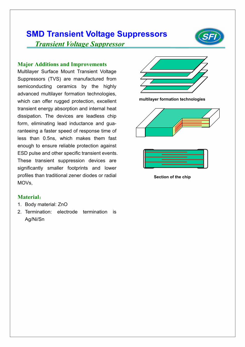
Major Additions and Improvements Multilayer Surface Mount Transient Voltage Suppressors (TVS) are manufactured from semiconducting ceramics by the highly advanced multilayer formation technologies, which can offer rugged protection, excellent transient energy absorption and internal heat dissipation. The devices are leadless chip form, eliminating lead inductance and gua- ranteeing a faster speed of response time of less than 0.5ns, which makes them fast enough to ensure reliable protection against ESD pulse and other specific transient events. These transient suppression devices are significantly smaller footprints and lower profiles than traditional zener diodes or radial MOVs, Material: 1. Body material: ZnO 2. Termination: electrode termination is
Ag/Ni/Sn
SMD Transient Voltage Suppressors Transient Voltage Suppressor
multilayer formation technologies
Section of the chip
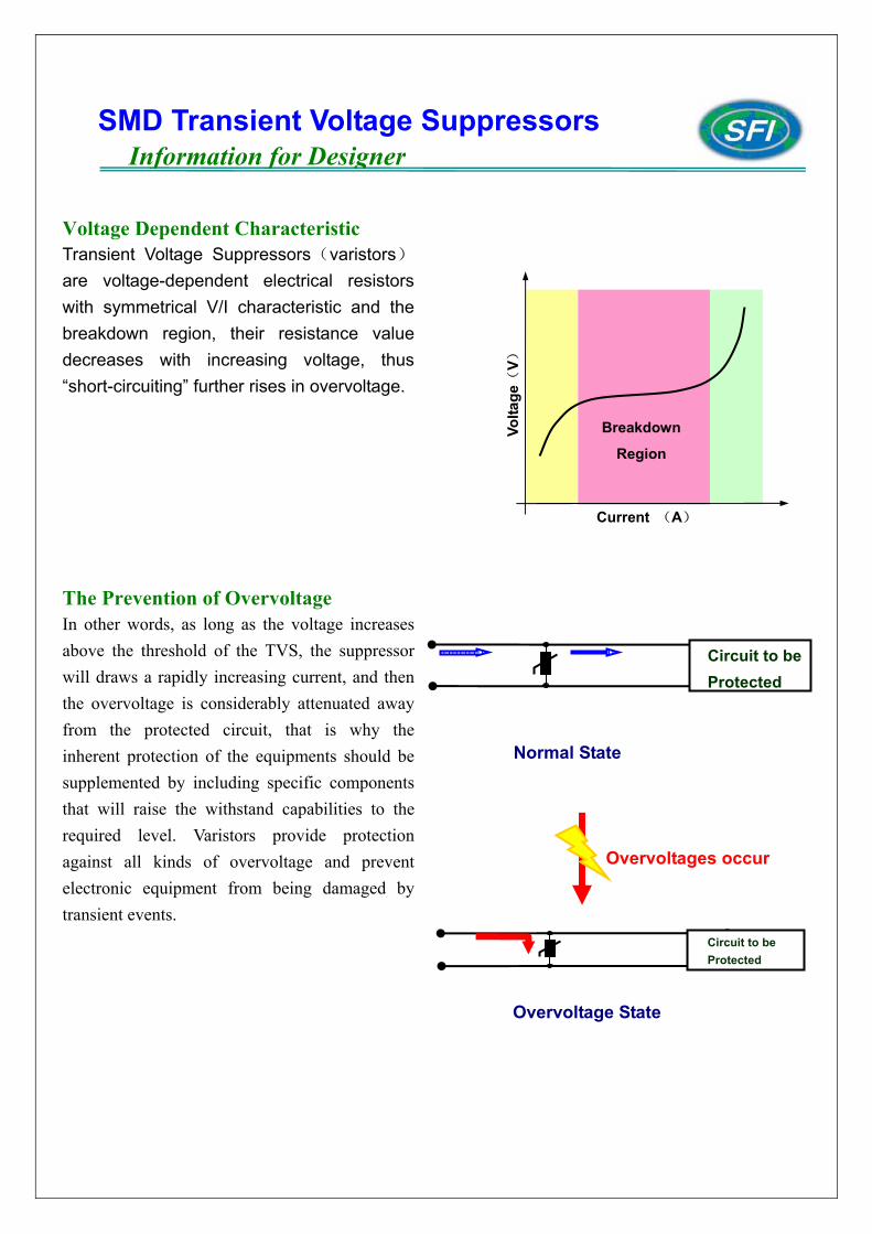
Voltage Dependent Characteristic Transient Voltage Suppressors(varistors) are voltage-dependent electrical resistors with symmetrical V/I characteristic and the breakdown region, their resistance value decreases with increasing voltage, thus “short-circuiting” further rises in overvoltage. The Prevention of Overvoltage In other words, as long as the voltage increases above the threshold of the TVS, the suppressor will draws a rapidly increasing current, and then the overvoltage is considerably attenuated away from the protected circuit, that is why the inherent protection of the equipments should be supplemented by including specific components that will raise the withstand capabilities to the required level. Varistors provide protection against all kinds of overvoltage and prevent electronic equipment from being damaged by transient events.
SMD Transient Voltage Suppressors Information for Designer
Breakdown
Region
Current (A) Vo
ltage
(V)
Circuit to be Protected
Normal State
Overvoltage State
Overvoltages occur
Circuit to be Protected
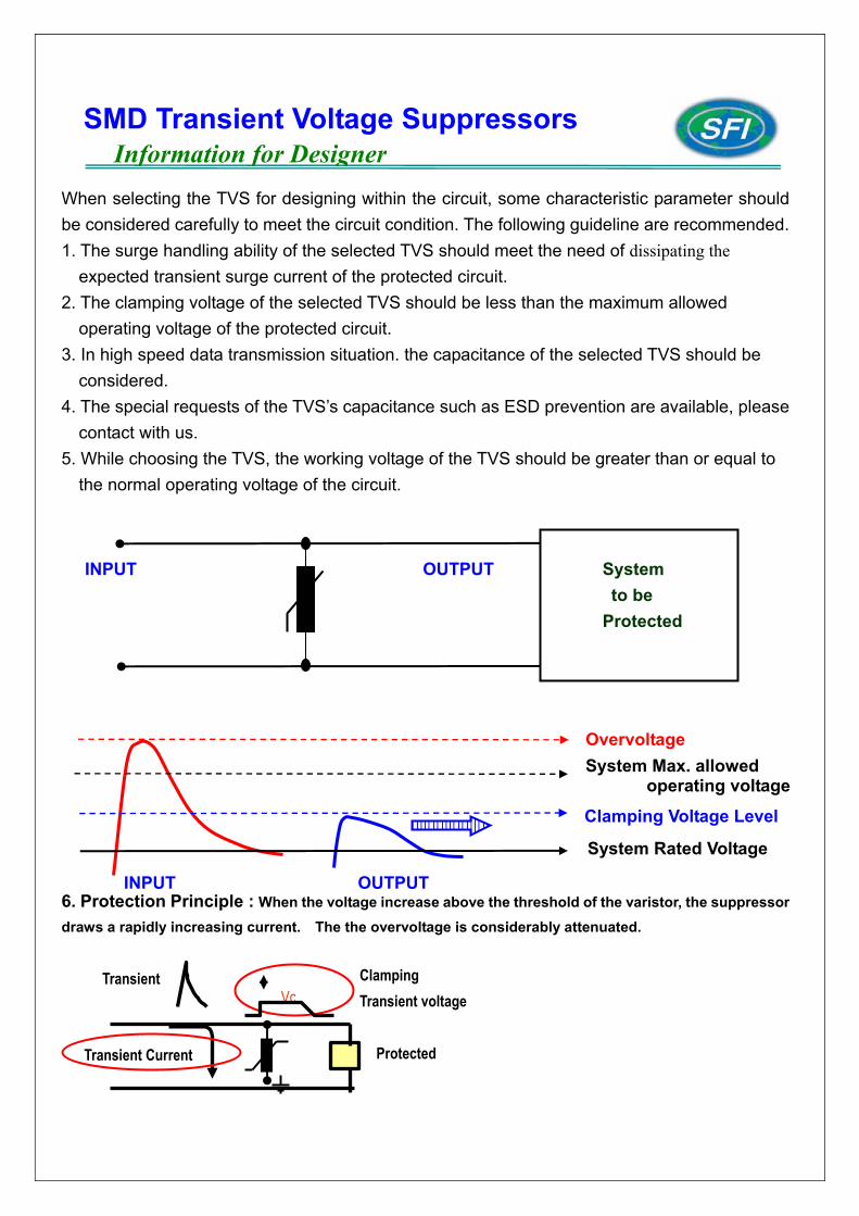
When selecting the TVS for designing within the circuit, some characteristic parameter should be considered carefully to meet the circuit condition. The following guideline are recommended. 1. The surge handling ability of the selected TVS should meet the need of dissipating the expected transient surge current of the protected circuit. 2. The clamping voltage of the selected TVS should be less than the maximum allowed
operating voltage of the protected circuit. 3. In high speed data transmission situation. the capacitance of the selected TVS should be considered. 4. The special requests of the TVS’s capacitance such as ESD prevention are available, please contact with us. 5. While choosing the TVS, the working voltage of the TVS should be greater than or equal to the normal operating voltage of the circuit. 6. Protection Principle : When the voltage increase above the threshold of the varistor, the suppressor draws a rapidly increasing current. The the overvoltage is considerably attenuated.
Transient Vc
Clamping Transient voltage
Transient Current Protected
SMD Transient Voltage Suppressors Information for Designer
Overvoltage
Clamping Voltage Level
System Rated Voltage
System Max. allowed operating voltage
System to be Protected
INPUT OUTPUT
OUTPUT INPUT
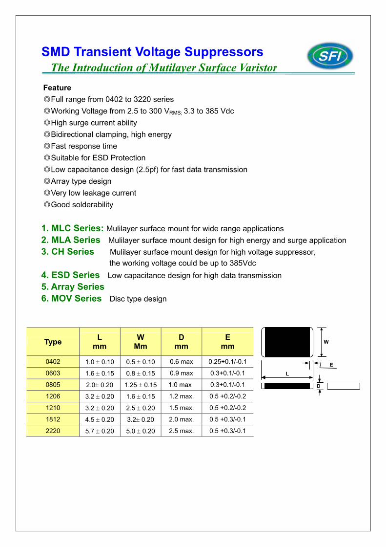
Feature
◎Full range from 0402 to 3220 series ◎Working Voltage from 2.5 to 300 VRMS; 3.3 to 385 Vdc ◎High surge current ability ◎Bidirectional clamping, high energy ◎Fast response time
◎Suitable for ESD Protection ◎Low capacitance design (2.5pf) for fast data transmission ◎Array type design ◎Very low leakage current ◎Good solderability
1. MLC Series: Mulilayer surface mount for wide range applications 2. MLA Series Mulilayer surface mount design for high energy and surge application 3. CH Series Mulilayer surface mount design for high voltage suppressor,
the working voltage could be up to 385Vdc 4. ESD Series Low capacitance design for high data transmission 5. Array Series 6. MOV Series Disc type design
Type L mm
W Mm
D mm
E mm
0402 1.0 ± 0.10 0.5 ± 0.10 0.6 max 0.25+0.1/-0.1
0603 1.6 ± 0.15 0.8 ± 0.15 0.9 max 0.3+0.1/-0.1
0805 2.0± 0.20 1.25 ± 0.15 1.0 max 0.3+0.1/-0.1
1206 3.2 ± 0.20 1.6 ± 0.15 1.2 max. 0.5 +0.2/-0.2
1210 3.2 ± 0.20 2.5 ± 0.20 1.5 max. 0.5 +0.2/-0.2
1812 4.5 ± 0.20 3.2± 0.20 2.0 max. 0.5 +0.3/-0.1
2220 5.7 ± 0.20 5.0 ± 0.20 2.5 max. 0.5 +0.3/-0.1
SMD Transient Voltage Suppressors The Introduction of Mutilayer Surface Varistor
W
L
D
E
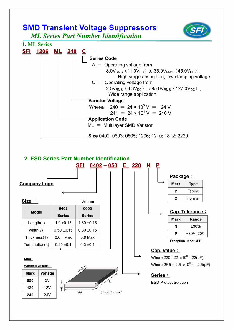
1. ML Series SFI 1206 ML 240 C
Series Code A = Operating voltage from 8.0VRMS(11.0VDC)to 35.0VRMS(45.0VDC), High surge absorption, low clamping voltage. C = Operating voltage from 2.5VRMS(3.3VDC)to 95.0VRMS(127.0VDC),
Wide range application. Varistor Voltage
Where: 240 = 24 × 100 V = 24 V 241 = 24 × 101 V = 240 V
Application Code ML = Multilayer SMD Varistor
Size 0402; 0603; 0805; 1206; 1210; 1812; 2220
SMD Transient Voltage Suppressors ML Series Part Number Identification
2. ESD Series Part Number Identification SFI 0402 – 050 E 220 N P
Cap. Value: Where 220 =22 ×100 = 22(pF)
Where 2R5 = 2.5 ×100 = 2.5(pF)
Size : Unit mm
Model 0402
Series
0603
Series
Length(L) 1.0 ±0.15 1.60 ±0.15
Width(W) 0.50 ±0.15 0.80 ±0.15
Thickness(T) 0.6 Max 0.9 Max
Termination(a) 0.25 ±0.1 0.3 ±0.1
Company Logo
Series: ESD Protect Solution
Package: Mark Type
P Taping
C normal
MAX
Working Voltage:
Mark Voltage
050 5V
120 12V
240 24V
Cap. Tolerance:Mark Range
N ±30%
P +80%-20%
Exception under 5PF
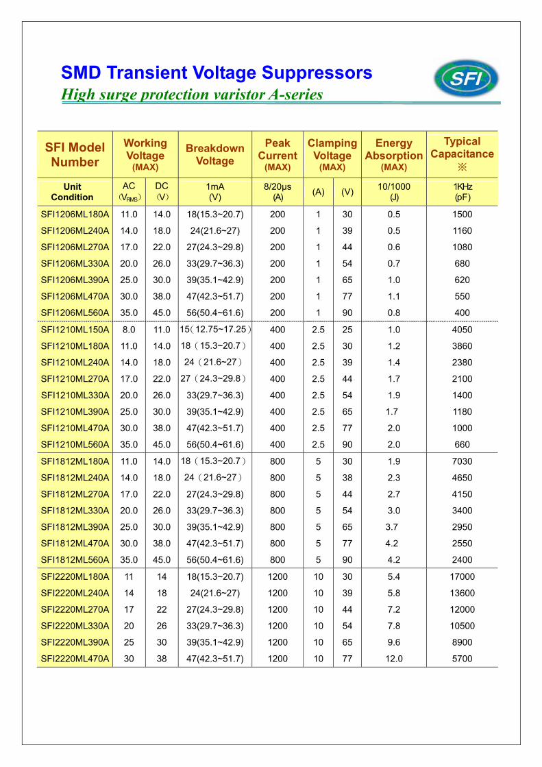
SFI Model Number
Working Voltage
(MAX)
Breakdown Voltage
Peak Current
(MAX)
ClampingVoltage
(MAX)
Energy Absorption
(MAX)
Typical Capacitance
※
Unit Condition
AC(VRMS)
DC (V)
1mA (V)
8/20µs (A) (A) (V) 10/1000
(J) 1KHz (pF)
SFI1206ML180A
SFI1206ML240A
SFI1206ML270A
SFI1206ML330A
SFI1206ML390A
SFI1206ML470A
SFI1206ML560A
11.0
14.0
17.0
20.0
25.0
30.0
35.0
14.0
18.0
22.0
26.0
30.0
38.0
45.0
18(15.3~20.7)
24(21.6~27)
27(24.3~29.8)
33(29.7~36.3)
39(35.1~42.9)
47(42.3~51.7)
56(50.4~61.6)
200
200
200
200
200
200
200
1
1
1
1
1
1
1
30
39
44
54
65
77
90
0.5
0.5
0.6
0.7
1.0
1.1
0.8
1500
1160
1080
680
620
550
400
SFI1210ML150A
SFI1210ML180A
SFI1210ML240A
SFI1210ML270A
SFI1210ML330A
SFI1210ML390A
SFI1210ML470A
SFI1210ML560A
8.0
11.0
14.0
17.0
20.0
25.0
30.0
35.0
11.0
14.0
18.0
22.0
26.0
30.0
38.0
45.0
15(12.75~17.25)
18(15.3~20.7)
24(21.6~27)
27(24.3~29.8)
33(29.7~36.3)
39(35.1~42.9)
47(42.3~51.7)
56(50.4~61.6)
400
400
400
400
400
400
400
400
2.5
2.5
2.5
2.5
2.5
2.5
2.5
2.5
25
30
39
44
54
65
77
90
1.0
1.2
1.4
1.7
1.9
1.7
2.0
2.0
4050
3860
2380
2100
1400
1180
1000
660
SFI1812ML180A
SFI1812ML240A
SFI1812ML270A
SFI1812ML330A
SFI1812ML390A
SFI1812ML470A
SFI1812ML560A
11.0
14.0
17.0
20.0
25.0
30.0
35.0
14.0
18.0
22.0
26.0
30.0
38.0
45.0
18(15.3~20.7)
24(21.6~27)
27(24.3~29.8)
33(29.7~36.3)
39(35.1~42.9)
47(42.3~51.7)
56(50.4~61.6)
800
800
800
800
800
800
800
5
5
5
5
5
5
5
30
38
44
54
65
77
90
1.9
2.3
2.7
3.0
3.7
4.2
4.2
7030
4650
4150
3400
2950
2550
2400
SFI2220ML180A
SFI2220ML240A
SFI2220ML270A
SFI2220ML330A
SFI2220ML390A
SFI2220ML470A
11
14
17
20
25
30
14
18
22
26
30
38
18(15.3~20.7)
24(21.6~27)
27(24.3~29.8)
33(29.7~36.3)
39(35.1~42.9)
47(42.3~51.7)
1200
1200
1200
1200
1200
1200
10
10
10
10
10
10
30
39
44
54
65
77
5.4
5.8
7.2
7.8
9.6
12.0
17000
13600
12000
10500
8900
5700
SMD Transient Voltage Suppressors High surge protection varistor A-series
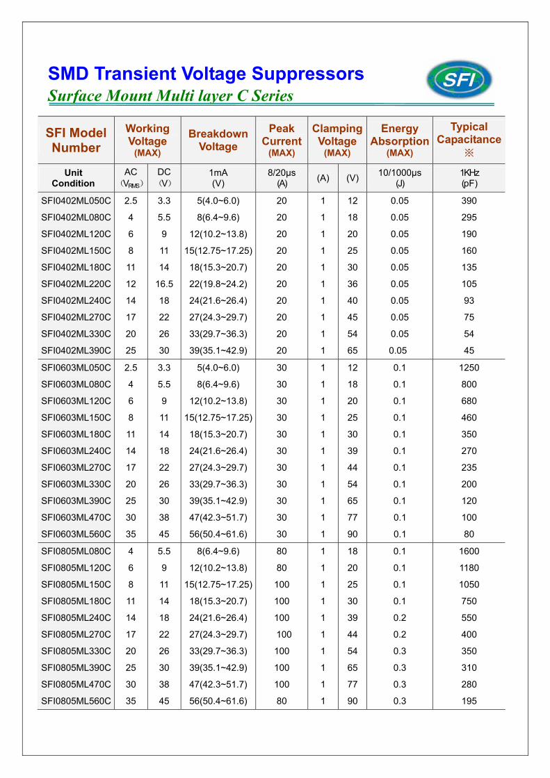
SFI Model Number
Working Voltage
(MAX)
Breakdown Voltage
Peak Current
(MAX)
ClampingVoltage
(MAX)
Energy Absorption
(MAX)
Typical Capacitance
※
Unit Condition
AC(VRMS)
DC (V)
1mA (V)
8/20µs (A) (A) (V) 10/1000µs
(J) 1KHz (pF)
SFI0402ML050C
SFI0402ML080C
SFI0402ML120C
SFI0402ML150C
SFI0402ML180C
SFI0402ML220C
SFI0402ML240C
SFI0402ML270C
SFI0402ML330C
SFI0402ML390C
2.5
4
6
8
11
12
14
17
20
25
3.3
5.5
9
11
14
16.5
18
22
26
30
5(4.0~6.0)
8(6.4~9.6)
12(10.2~13.8)
15(12.75~17.25)
18(15.3~20.7)
22(19.8~24.2)
24(21.6~26.4)
27(24.3~29.7)
33(29.7~36.3)
39(35.1~42.9)
20
20
20
20
20
20
20
20
20
20
1
1
1
1
1
1
1
1
1
1
12
18
20
25
30
36
40
45
54
65
0.05
0.05
0.05
0.05
0.05
0.05
0.05
0.05
0.05
0.05
390
295
190
160
135
105
93
75
54
45
SFI0603ML050C
SFI0603ML080C
SFI0603ML120C
SFI0603ML150C
SFI0603ML180C
SFI0603ML240C
SFI0603ML270C
SFI0603ML330C
SFI0603ML390C
SFI0603ML470C
SFI0603ML560C
2.5
4
6
8
11
14
17
20
25
30
35
3.3
5.5
9
11
14
18
22
26
30
38
45
5(4.0~6.0)
8(6.4~9.6)
12(10.2~13.8)
15(12.75~17.25)
18(15.3~20.7)
24(21.6~26.4)
27(24.3~29.7)
33(29.7~36.3)
39(35.1~42.9)
47(42.3~51.7)
56(50.4~61.6)
30
30
30
30
30
30
30
30
30
30
30
1
1
1
1
1
1
1
1
1
1
1
12
18
20
25
30
39
44
54
65
77
90
0.1
0.1
0.1
0.1
0.1
0.1
0.1
0.1
0.1
0.1
0.1
1250
800
680
460
350
270
235
200
120
100
80
SFI0805ML080C
SFI0805ML120C
SFI0805ML150C
SFI0805ML180C
SFI0805ML240C
SFI0805ML270C
SFI0805ML330C
SFI0805ML390C
SFI0805ML470C
SFI0805ML560C
4
6
8
11
14
17
20
25
30
35
5.5
9
11
14
18
22
26
30
38
45
8(6.4~9.6)
12(10.2~13.8)
15(12.75~17.25)
18(15.3~20.7)
24(21.6~26.4)
27(24.3~29.7)
33(29.7~36.3)
39(35.1~42.9)
47(42.3~51.7)
56(50.4~61.6)
80
80
100
100
100
100
100
100
100
80
1
1
1
1
1
1
1
1
1
1
18
20
25
30
39
44
54
65
77
90
0.1
0.1
0.1
0.1
0.2
0.2
0.3
0.3
0.3
0.3
1600
1180
1050
750
550
400
350
310
280
195
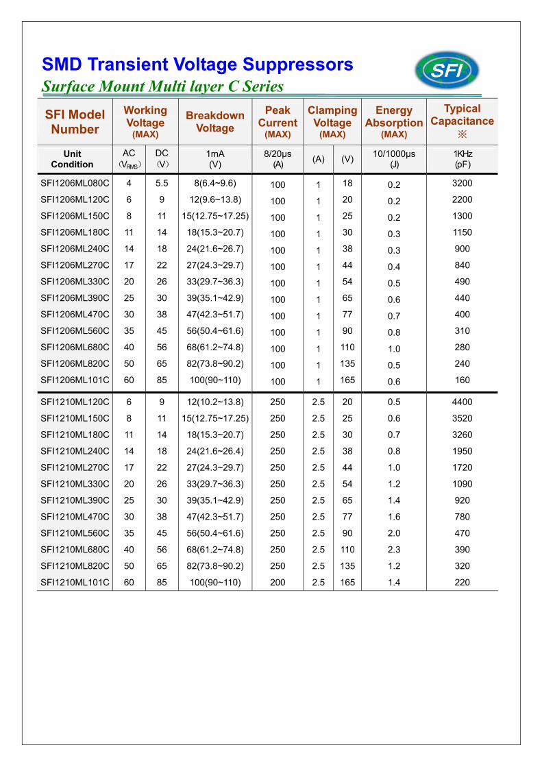
SMD Transient Voltage Suppressors Surface Mount Multi layer C Series
SFI Model Number
Working Voltage
(MAX)
Breakdown Voltage
Peak Current
(MAX)
ClampingVoltage
(MAX)
Energy Absorption
(MAX)
Typical Capacitance
※
Unit Condition
AC(VRMS)
DC (V)
1mA (V)
8/20µs (A) (A) (V) 10/1000µs
(J) 1KHz (pF)
SFI1206ML080C
SFI1206ML120C
SFI1206ML150C
SFI1206ML180C
SFI1206ML240C
SFI1206ML270C
SFI1206ML330C
SFI1206ML390C
SFI1206ML470C
SFI1206ML560C
SFI1206ML680C
SFI1206ML820C
SFI1206ML101C
4
6
8
11
14
17
20
25
30
35
40
50
60
5.5
9
11
14
18
22
26
30
38
45
56
65
85
8(6.4~9.6)
12(9.6~13.8)
15(12.75~17.25)
18(15.3~20.7)
24(21.6~26.7)
27(24.3~29.7)
33(29.7~36.3)
39(35.1~42.9)
47(42.3~51.7)
56(50.4~61.6)
68(61.2~74.8)
82(73.8~90.2)
100(90~110)
100
100
100
100
100
100
100
100
100
100
100
100
100
1
1
1
1
1
1
1
1
1
1
1
1
1
18
20
25
30
38
44
54
65
77
90
110
135
165
0.2
0.2
0.2
0.3
0.3
0.4
0.5
0.6
0.7
0.8
1.0
0.5
0.6
3200
2200
1300
1150
900
840
490
440
400
310
280
240
160
SFI1210ML120C
SFI1210ML150C
SFI1210ML180C
SFI1210ML240C
SFI1210ML270C
SFI1210ML330C
SFI1210ML390C
SFI1210ML470C
SFI1210ML560C
SFI1210ML680C
SFI1210ML820C
SFI1210ML101C
6
8
11
14
17
20
25
30
35
40
50
60
9
11
14
18
22
26
30
38
45
56
65
85
12(10.2~13.8)
15(12.75~17.25)
18(15.3~20.7)
24(21.6~26.4)
27(24.3~29.7)
33(29.7~36.3)
39(35.1~42.9)
47(42.3~51.7)
56(50.4~61.6)
68(61.2~74.8)
82(73.8~90.2)
100(90~110)
250
250
250
250
250
250
250
250
250
250
250
200
2.5
2.5
2.5
2.5
2.5
2.5
2.5
2.5
2.5
2.5
2.5
2.5
20
25
30
38
44
54
65
77
90
110
135
165
0.5
0.6
0.7
0.8
1.0
1.2
1.4
1.6
2.0
2.3
1.2
1.4
4400
3520
3260
1950
1720
1090
920
780
470
390
320
220
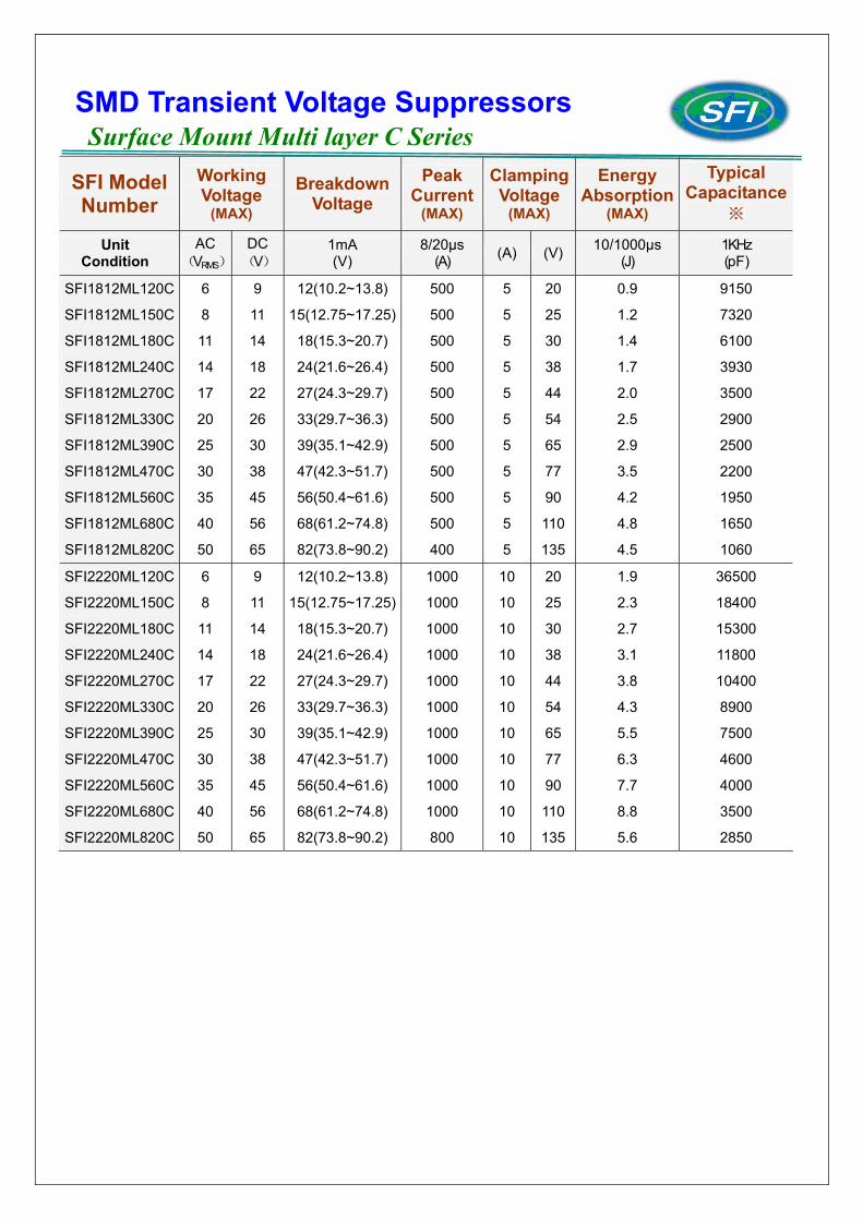
SMD Transient Voltage Suppressors Surface Mount Multi layer C Series
SFI Model Number
Working Voltage
(MAX)
Breakdown Voltage
Peak Current
(MAX)
ClampingVoltage
(MAX)
Energy Absorption
(MAX)
Typical Capacitance
※
Unit Condition
AC(VRMS)
DC (V)
1mA (V)
8/20µs (A) (A) (V) 10/1000µs
(J) 1KHz (pF)
SFI1812ML120C
SFI1812ML150C
SFI1812ML180C
SFI1812ML240C
SFI1812ML270C
SFI1812ML330C
SFI1812ML390C
SFI1812ML470C
SFI1812ML560C
SFI1812ML680C
SFI1812ML820C
6
8
11
14
17
20
25
30
35
40
50
9
11
14
18
22
26
30
38
45
56
65
12(10.2~13.8)
15(12.75~17.25)
18(15.3~20.7)
24(21.6~26.4)
27(24.3~29.7)
33(29.7~36.3)
39(35.1~42.9)
47(42.3~51.7)
56(50.4~61.6)
68(61.2~74.8)
82(73.8~90.2)
500
500
500
500
500
500
500
500
500
500
400
5
5
5
5
5
5
5
5
5
5
5
20
25
30
38
44
54
65
77
90
110
135
0.9
1.2
1.4
1.7
2.0
2.5
2.9
3.5
4.2
4.8
4.5
9150
7320
6100
3930
3500
2900
2500
2200
1950
1650
1060
SFI2220ML120C
SFI2220ML150C
SFI2220ML180C
SFI2220ML240C
SFI2220ML270C
SFI2220ML330C
SFI2220ML390C
SFI2220ML470C
SFI2220ML560C
SFI2220ML680C
SFI2220ML820C
6
8
11
14
17
20
25
30
35
40
50
9
11
14
18
22
26
30
38
45
56
65
12(10.2~13.8)
15(12.75~17.25)
18(15.3~20.7)
24(21.6~26.4)
27(24.3~29.7)
33(29.7~36.3)
39(35.1~42.9)
47(42.3~51.7)
56(50.4~61.6)
68(61.2~74.8)
82(73.8~90.2)
1000
1000
1000
1000
1000
1000
1000
1000
1000
1000
800
10
10
10
10
10
10
10
10
10
10
10
20
25
30
38
44
54
65
77
90
110
135
1.9
2.3
2.7
3.1
3.8
4.3
5.5
6.3
7.7
8.8
5.6
36500
18400
15300
11800
10400
8900
7500
4600
4000
3500
2850
SMD Transient Voltage Suppressors Surface Mount Multi layer C Series
MODEL
NUMBER MAXIMUM RATING(TA=125℃) CHARACTERISTICS(TA=25℃)
SFI Model Number
MAX. ALLOWABLE
VOLTAGE
SURGE
CURRENT
ENERGY
ABSORPTION
(10/1000µs)
MAX. CLAMPING VOLTAGE
VARISTOR VOLTAGE
TYPICAL CAPACITANCE
Thickness
T± 1
AC(VRMS) DC(V) 8/20µs(A) (J) (A) (V) (V) pF(KHz) (mm)
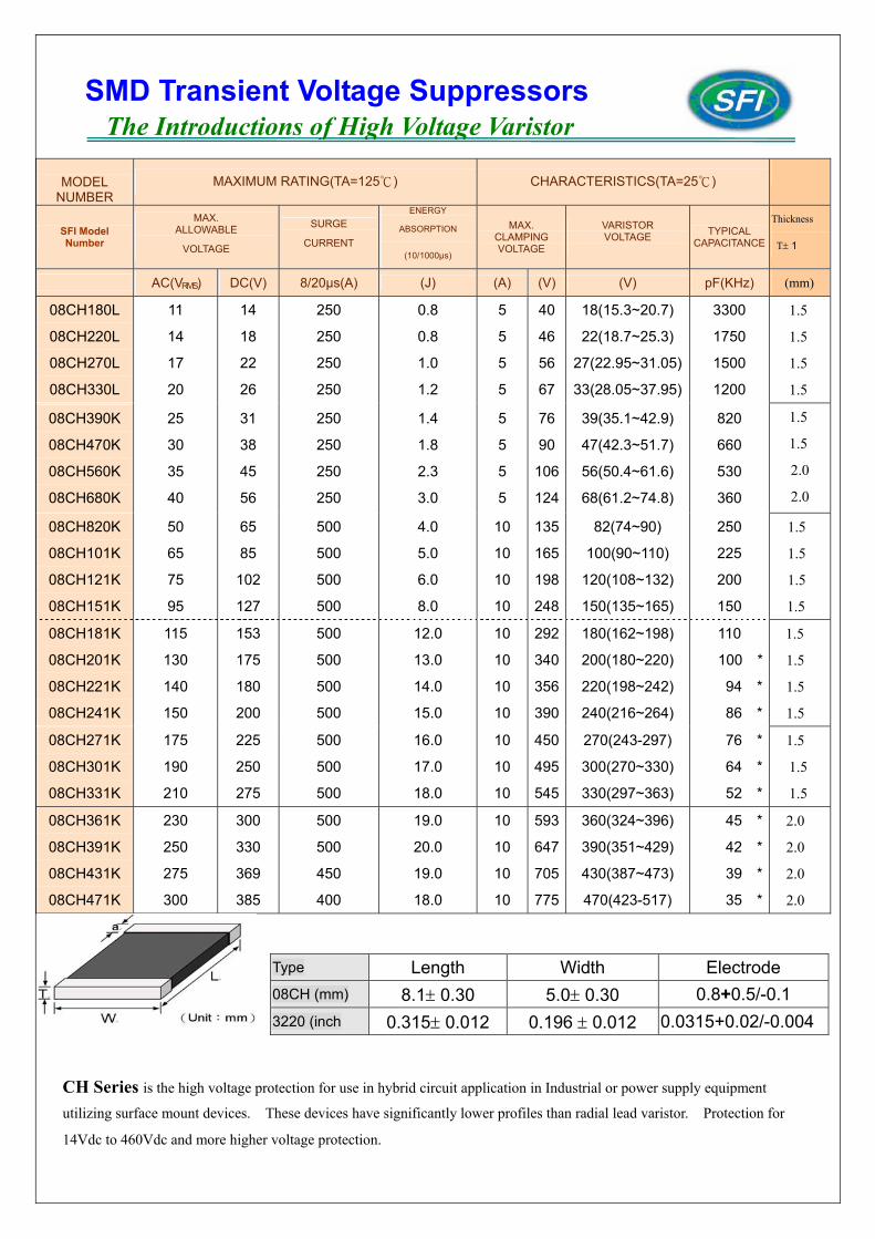
08CH180L
08CH220L
08CH270L
08CH330L
11
14
17
20
14
18
22
26
250
250
250
250
0.8
0.8
1.0
1.2
5
5
5
5
40
46
56
67
18(15.3~20.7)
22(18.7~25.3)
27(22.95~31.05)
33(28.05~37.95)
3300
1750
1500
1200
1.5
1.5
1.5
1.5
08CH390K
08CH470K
08CH560K
08CH680K
25
30
35
40
31
38
45
56
250
250
250
250
1.4
1.8
2.3
3.0
5
5
5
5
76
90
106
124
39(35.1~42.9)
47(42.3~51.7)
56(50.4~61.6)
68(61.2~74.8)
820
660
530
360
1.5
1.5
2.0
2.0
08CH820K
08CH101K
08CH121K
08CH151K
50
65
75
95
65
85
102
127
500
500
500
500
4.0
5.0
6.0
8.0
10
10
10
10
135
165
198
248
82(74~90)
100(90~110)
120(108~132)
150(135~165)
250
225
200
150
1.5
1.5
1.5
1.5
08CH181K
08CH201K
08CH221K
08CH241K
115
130
140
150
153
175
180
200
500
500
500
500
12.0
13.0
14.0
15.0
10
10
10
10
292
340
356
390
180(162~198)
200(180~220)
220(198~242)
240(216~264)
110
100 *
94 *
86 *
1.5
1.5
1.5
1.5
08CH271K
08CH301K
08CH331K
175
190
210
225
250
275
500
500
500
16.0
17.0
18.0
10
10
10
450
495
545
270(243-297)
300(270~330)
330(297~363)
76 *
64 *
52 *
1.5
1.5
1.5
08CH361K
08CH391K
08CH431K
08CH471K
230
250
275
300
300
330
369
385
500
500
450
400
19.0
20.0
19.0
18.0
10
10
10
10
593
647
705
775
360(324~396)
390(351~429)
430(387~473)
470(423-517)
45 *
42 *
39 *
35 *
2.0
2.0
2.0
2.0
CH Series is the high voltage protection for use in hybrid circuit application in Industrial or power supply equipment
utilizing surface mount devices. These devices have significantly lower profiles than radial lead varistor. Protection for
14Vdc to 460Vdc and more higher voltage protection.
Type Length Width Electrode 08CH (mm) 8.1± 0.30 5.0± 0.30 0.8+0.5/-0.1 3220 (inch 0.315± 0.012 0.196 ± 0.012 0.0315+0.02/-0.004
SMD Transient Voltage Suppressors The Introductions of High Voltage Varistor
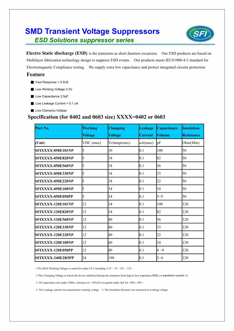
Electro Static discharge (ESD) is the transients as short duration excursion. Our ESD products are based on
Multilayer fabrication technology design to suppress ESD events. Our products meets IEC61000-4-2 standard for
Electromagnetic Compliance testing. We supply extra low capacitance and protect integrated circuits protection
Feature
Specification (for 0402 and 0603 size) XXXX=0402 or 0603
1 The MAX Working Voltage is suited for under 24 V including 3.3V、5V、8V、12V。
2.This Clamping Voltage at which the device stabilized during the transition from high to low impedance 8/20μs waveform current 1A
3. All capacitance test under 1MHz, tolerance at +-30%(N) exception under 5pF for +80% -20%。
4. The Leakage current was measured at working voltage 5. The Insulation Resistor was measured at working voltage
Part No, Working
Voltage
Clamping
Voltage
Leakage
Current
Capacitance
Volume
Insulation
Resistance
(Unit) VDC (max) Vclamp(max) uA(max) pF Ohm(Min)
SFIXXXX-050E101NP 5 30 0.1 100 50
SFIXXXX-050E820NP 5 34 0.1 82 50
SFIXXXX-050E560NP 5 34 0.1 56 50
SFIXXXX-050E330NP 5 34 0.1 33 50
SFIXXXX-050E220NP 5 34 0.1 22 50
SFIXXXX-050E100NP 5 34 0.1 10 50
SFIXXXX-050E050PP 5 34 0.1 5~9 50
SFIXXXX-120E101NP 12 34 0.1 100 120
SFIXXXX-120E820NP 12 34 0.1 82 120
SFIXXXX-120E560NP 12 40 0.1 56 120
SFIXXXX-120E330NP 12 40 0.1 33 120
SFIXXXX-120E220NP 12 40 0.1 22 120
SFIXXXX-120E100NP 12 60 0.1 10 120
SFIXXXX-120E050PP 12 80 0.1 4 ~9 120
SFIXXXX-240E2R5PP 24 198 0.1 2~4 120
SMD Transient Voltage Suppressors ESD Solutions suppressor series
■ Fast Response < 0.5nS
■ Low Working Voltage 3.3V
■ Low Capacitance 2.5pF
■ Low Leakage Current < 0.1 uA
■ Low Clamping Voltage
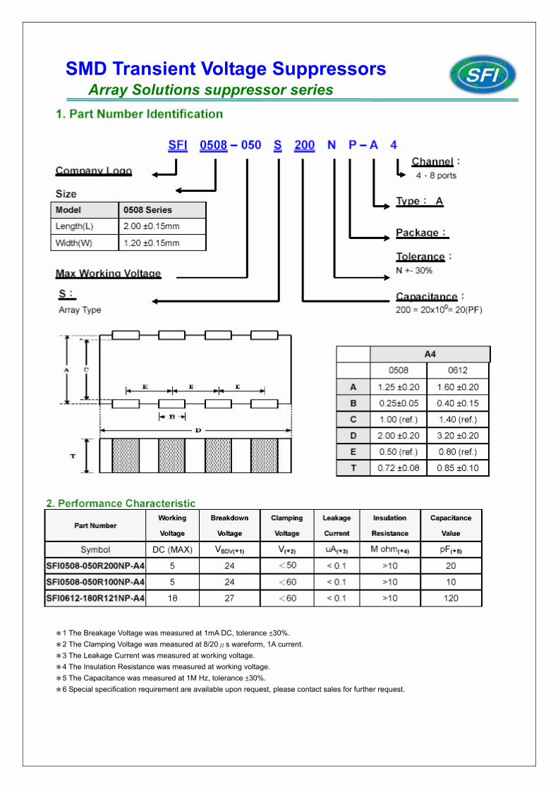
*1 The Breakage Voltage was measured at 1mA DC, tolerance ±30%. *2 The Clamping Voltage was measured at 8/20μs wareform, 1A current. *3 The Leakage Current was measured at working voltage. *4 The Insulation Resistance was measured at working voltage. *5 The Capacitance was measured at 1M Hz, tolerance ±30%. *6 Special specification requirement are available upon request, please contact sales for further request.
SMD Transient Voltage Suppressors Array Solutions suppressor series
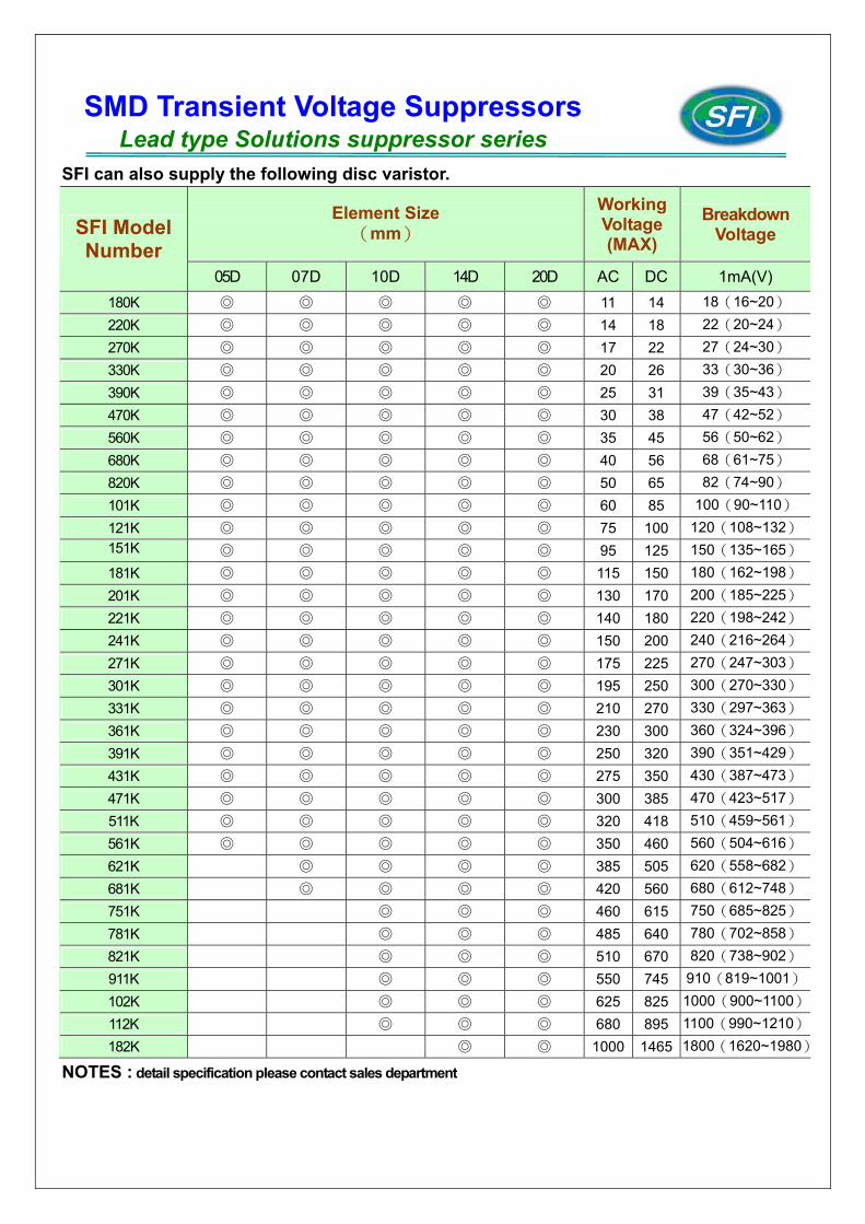
SFI can also supply the following disc varistor.
Element Size (mm)
Working Voltage (MAX)
Breakdown Voltage SFI Model
Number 05D 07D 10D 14D 20D AC DC 1mA(V)
180K ◎ ◎ ◎ ◎ ◎ 11 14 18(16~20) 220K ◎ ◎ ◎ ◎ ◎ 14 18 22(20~24) 270K ◎ ◎ ◎ ◎ ◎ 17 22 27(24~30) 330K ◎ ◎ ◎ ◎ ◎ 20 26 33(30~36) 390K ◎ ◎ ◎ ◎ ◎ 25 31 39(35~43) 470K ◎ ◎ ◎ ◎ ◎ 30 38 47(42~52) 560K ◎ ◎ ◎ ◎ ◎ 35 45 56(50~62) 680K ◎ ◎ ◎ ◎ ◎ 40 56 68(61~75) 820K ◎ ◎ ◎ ◎ ◎ 50 65 82(74~90) 101K ◎ ◎ ◎ ◎ ◎ 60 85 100(90~110) 121K ◎ ◎ ◎ ◎ ◎ 75 100 120(108~132)151K ◎ ◎ ◎ ◎ ◎ 95 125 150(135~165)181K ◎ ◎ ◎ ◎ ◎ 115 150 180(162~198)201K ◎ ◎ ◎ ◎ ◎ 130 170 200(185~225)221K ◎ ◎ ◎ ◎ ◎ 140 180 220(198~242)241K ◎ ◎ ◎ ◎ ◎ 150 200 240(216~264)271K ◎ ◎ ◎ ◎ ◎ 175 225 270(247~303)301K ◎ ◎ ◎ ◎ ◎ 195 250 300(270~330)331K ◎ ◎ ◎ ◎ ◎ 210 270 330(297~363)361K ◎ ◎ ◎ ◎ ◎ 230 300 360(324~396)391K ◎ ◎ ◎ ◎ ◎ 250 320 390(351~429)431K ◎ ◎ ◎ ◎ ◎ 275 350 430(387~473)471K ◎ ◎ ◎ ◎ ◎ 300 385 470(423~517)511K ◎ ◎ ◎ ◎ ◎ 320 418 510(459~561)561K ◎ ◎ ◎ ◎ ◎ 350 460 560(504~616)621K ◎ ◎ ◎ ◎ 385 505 620(558~682)681K ◎ ◎ ◎ ◎ 420 560 680(612~748)751K ◎ ◎ ◎ 460 615 750(685~825)781K ◎ ◎ ◎ 485 640 780(702~858)821K ◎ ◎ ◎ 510 670 820(738~902)911K ◎ ◎ ◎ 550 745 910(819~1001)102K ◎ ◎ ◎ 625 825 1000(900~1100)112K ◎ ◎ ◎ 680 895 1100(990~1210)182K ◎ ◎ 1000 1465 1800(1620~1980)
NOTES : detail specification please contact sales department
SMD Transient Voltage Suppressors Lead type Solutions suppressor series
SFI have the strong R&D team to continual producing new overvoltage protection for Customer valued application and circuit protection. We supply customer all series protection from low voltage to high voltage and from single type to array type. Now our product roadmap are including following. More detail schedule and product specification, please contact our sales team for further request.
1. Extra low capacitance (0.5pf) ESD protection Chip varistor the material is ZnO and the low capacitance need very high technical to production. SFI have the strong technical and our current mass production item capacitance is 2.5pf. We still keep continual making research for under 0.5pf capacitance for customer application.
2. Low voltage Array series type We are also making develop item of array 0508 and 0612 series for the working voltage lower 12.5V and low capacitance request.
3. ESD and EMI function together Array products We also making new item of array with EMI function for customer.
SMD Transient Voltage Suppressors New Development and product roadmap item
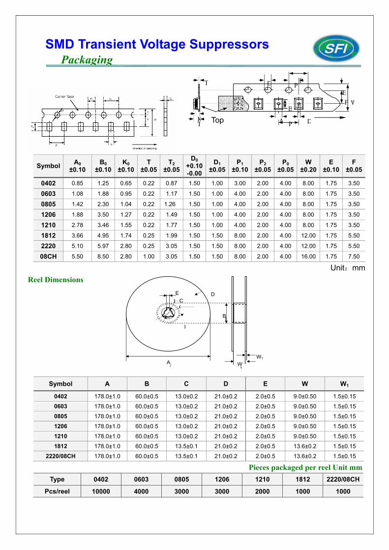
Symbol A0 ±0.10
B0 ±0.10
K0 ±0.10
T ±0.05
T2 ±0.05
D0 +0.10-0.00
D1 ±0.05
P1 ±0.10
P2 ±0.05
P0 ±0.05
W ±0.20
E ±0.10
F ±0.05
0402 0.85 1.25 0.65 0.22 0.87 1.50 1.00 3.00 2.00 4.00 8.00 1.75 3.50
0603 1.08 1.88 0.95 0.22 1.17 1.50 1.00 4.00 2.00 4.00 8.00 1.75 3.50
0805 1.42 2.30 1.04 0.22 1.26 1.50 1.00 4.00 2.00 4.00 8.00 1.75 3.50
1206 1.88 3.50 1.27 0.22 1.49 1.50 1.00 4.00 2.00 4.00 8.00 1.75 3.50
1210 2.78 3.46 1.55 0.22 1.77 1.50 1.00 4.00 2.00 4.00 8.00 1.75 3.50
1812 3.66 4.95 1.74 0.25 1.99 1.50 1.50 8.00 2.00 4.00 12.00 1.75 5.50
2220 5.10 5.97 2.80 0.25 3.05 1.50 1.50 8.00 2.00 4.00 12.00 1.75 5.50
08CH 5.50 8.50 2.80 1.00 3.05 1.50 1.50 8.00 2.00 4.00 16.00 1.75 7.50
Unit:mm Reel Dimensions
Pieces packaged per reel Unit mmType 0402 0603 0805 1206 1210 1812 2220/08CH
Pcs/reel 10000 4000 3000 3000 2000 1000 1000
Symbol A B C D E W W1
0402 178.0±1.0 60.0±0.5 13.0±0.2 21.0±0.2 2.0±0.5 9.0±0.50 1.5±0.15
0603 178.0±1.0 60.0±0.5 13.0±0.2 21.0±0.2 2.0±0.5 9.0±0.50 1.5±0.15
0805 178.0±1.0 60.0±0.5 13.0±0.2 21.0±0.2 2.0±0.5 9.0±0.50 1.5±0.15
1206 178.0±1.0 60.0±0.5 13.0±0.2 21.0±0.2 2.0±0.5 9.0±0.50 1.5±0.15
1210 178.0±1.0 60.0±0.5 13.0±0.2 21.0±0.2 2.0±0.5 9.0±0.50 1.5±0.15
1812 178.0±1.0 60.0±0.5 13.5±0.1 21.0±0.2 2.0±0.5 13.6±0.2 1.5±0.15
2220/08CH 178.0±1.0 60.0±0.5 13.5±0.1 21.0±0.2 2.0±0.5 13.6±0.2 1.5±0.15
EC
D
A
B
W WA
B
CE
W1
D
SMD Transient Voltage Suppressors Packaging
A P D
B
D PP
EWF
Top
T
KT
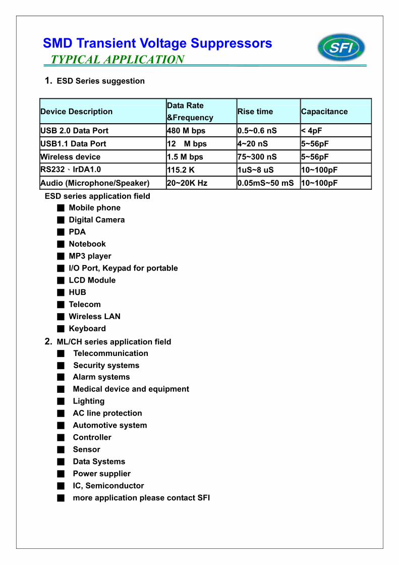
1. ESD Series suggestion
Device Description Data Rate &Frequency
Rise time Capacitance
USB 2.0 Data Port 480 M bps 0.5~0.6 nS < 4pF USB1.1 Data Port 12 M bps 4~20 nS 5~56pF Wireless device 1.5 M bps 75~300 nS 5~56pF RS232、IrDA1.0 115.2 K 1uS~8 uS 10~100pF Audio (Microphone/Speaker) 20~20K Hz 0.05mS~50 mS 10~100pF
ESD series application field ■ Mobile phone ■ Digital Camera ■ PDA ■ Notebook ■ MP3 player ■ I/O Port, Keypad for portable ■ LCD Module ■ HUB ■ Telecom ■ Wireless LAN ■ Keyboard
2. ML/CH series application field ■ Telecommunication ■ Security systems ■ Alarm systems ■ Medical device and equipment ■ Lighting ■ AC line protection ■ Automotive system ■ Controller ■ Sensor ■ Data Systems ■ Power supplier ■ IC, Semiconductor ■ more application please contact SFI
SMD Transient Voltage Suppressors TYPICAL APPLICATION
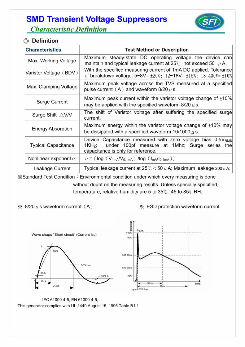
◎ Definition Characteristics Test Method or Description
Max. Working Voltage Maximum steady-state DC operating voltage the device can maintain and typical leakage current at 25℃ not exceed 50 μA.
Varistor Voltage(BDV) With the specified measuring current of 1mA DC applied. Tolerance of breakdown voltage: 5~8V= ±20%; 12~18V= ±15%; 18~430V= ±10%
Max. Clamping Voltage Maximum peak voltage across the TVS measured at a specified pulse current(A)and waveform 8/20μs.
Surge Current Maximum peak current within the varistor voltage change of ±10% may be applied with the specified waveform 8/20μs.
Surge Shift △V/V The shift of Varistor voltage after suffering the specified surge current.
Energy Absorption Maximum energy within the varistor voltage change of ±10% may be dissipated with a specified waveform 10/1000μs .
Typical Capacitance Device Capacitance measured with zero voltage bias 0.5VRMS1KHZ; under 100pf measure at 1Mhz; Surge series the capacitance is only for reference.
Nonlinear exponentα α=〔log(V1mA/V0.1mA)/log(ImA/I0.1mA)〕
Leakage Current Typical leakage current at 25℃<50μA; Maximum leakage 200μA;
※Standard Test Condition:Environmental condition under which every measuring is done without doubt on the measuring results. Unless specially specified, temperature, relative humidity are 5 to 35℃, 45 to 85﹪RH.
※ 8/20μs waveform current(A) ※ ESD protection waveform current
IEC 61000-4-5, EN 61000-4-5, This generator complies with UL 1449 August 15. 1996 Table B1.1
SMD Transient Voltage Suppressors Characteristic Definition
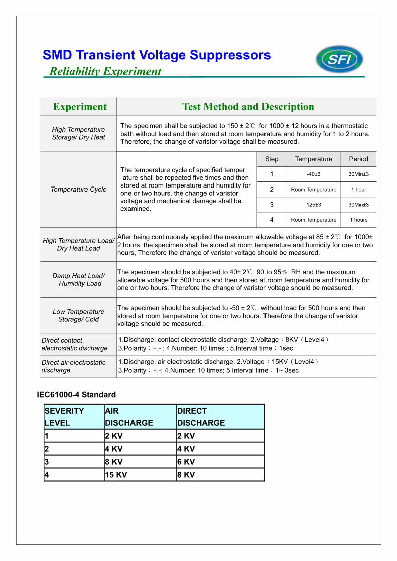
Experiment Test Method and Description
High Temperature Storage/ Dry Heat
The specimen shall be subjected to 150 ± 2℃ for 1000 ± 12 hours in a thermostatic bath without load and then stored at room temperature and humidity for 1 to 2 hours. Therefore, the change of varistor voltage shall be measured.
Step Temperature Period
1 -40±3 30Min±3
2 Room Temperature 1 hour
3 125±3 30Min±3
Temperature Cycle
The temperature cycle of specified temper -ature shall be repeated five times and then stored at room temperature and humidity for one or two hours. the change of varistor voltage and mechanical damage shall be examined.
4 Room Temperature 1 hours
High Temperature Load/ Dry Heat Load
After being continuously applied the maximum allowable voltage at 85 ± 2℃ for 1000± 2 hours, the specimen shall be stored at room temperature and humidity for one or two hours, Therefore the change of varistor voltage should be measured.
Damp Heat Load/ Humidity Load
The specimen should be subjected to 40± 2℃, 90 to 95﹪ RH and the maximum allowable voltage for 500 hours and then stored at room temperature and humidity for one or two hours. Therefore the change of varistor voltage should be measured.
Low Temperature Storage/ Cold
The specimen should be subjected to -50 ± 2℃, without load for 500 hours and then stored at room temperature for one or two hours. Therefore the change of varistor voltage should be measured.
Direct contact electrostatic discharge
1.Discharge: contact electrostatic discharge; 2.Voltage:8KV(Level4) 3.Polarity:+,- ; 4.Number: 10 times ; 5.Interval time:1sec
Direct air electrostatic discharge
1.Discharge: air electrostatic discharge; 2.Voltage:15KV(Level4) 3.Polarity:+,-; 4.Number: 10 times; 5.Interval time:1~ 3sec
IEC61000-4 Standard
SEVERITY LEVEL
AIR DISCHARGE
DIRECT DISCHARGE
1 2 KV 2 KV 2 4 KV 4 KV 3 8 KV 6 KV 4 15 KV 8 KV
SMD Transient Voltage Suppressors Reliability Experiment
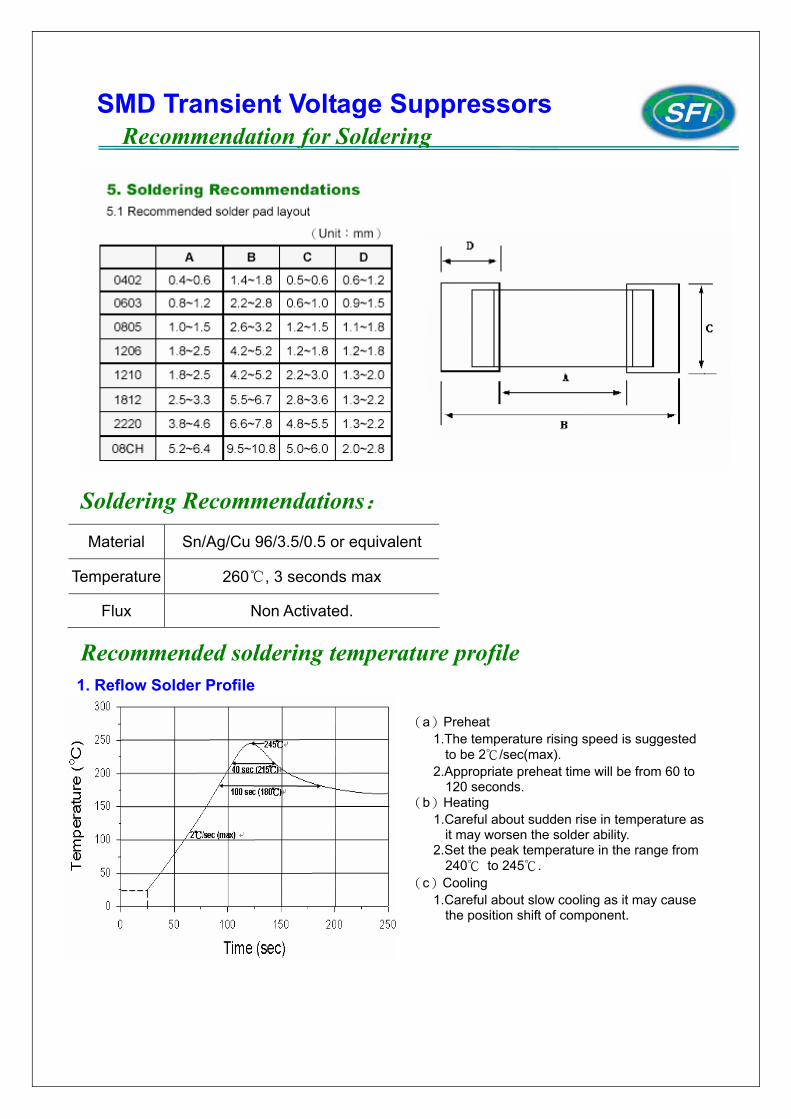
Soldering Recommendations: Material Sn/Ag/Cu 96/3.5/0.5 or equivalent
Temperature 260℃, 3 seconds max
Flux Non Activated.
Recommended soldering temperature profile
1. Reflow Solder Profile
SMD Transient Voltage Suppressors Recommendation for Soldering
(a)Preheat 1.The temperature rising speed is suggested
to be 2℃/sec(max). 2.Appropriate preheat time will be from 60 to
120 seconds. (b)Heating
1.Careful about sudden rise in temperature as it may worsen the solder ability.
2.Set the peak temperature in the range from 240℃ to 245℃.
(c)Cooling 1.Careful about slow cooling as it may cause
the position shift of component.
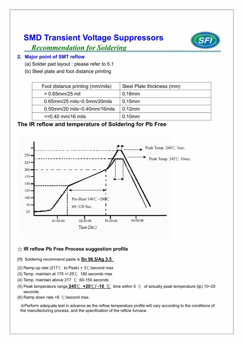
2. Major point of SMT reflow
(a) Solder pad layout : please refer to 5.1 (b) Steel plate and foot distance printing
Foot distance printing (mm/mils) Steel Plate thickness (mm) > 0.65mm/25 mil 0.18mm 0.65mm/25 mils~0.5mm/20mils 0.15mm 0.50mm/20 mils~0.40mm/16mils 0.12mm <=0.40 mm/16 mils 0.10mm
The IR reflow and temperature of Soldering for Pb Free
☆ IR reflow Pb Free Process suggestion profile
(1) Soldering recommend paste is Sn 96.5/Ag 3.5
(2) Ramp-up rate (217℃ to Peak) + 3℃/second max (3) Temp. maintain at 175 +/-25℃ 180 seconds max (4) Temp. maintain above 217 ℃ 60-150 seconds (5) Peak temperature range 245℃ +20℃/ -10 ℃ time within 5 ℃ of actually peak temperature (tp) 10~20
seconds (6) Ramp down rate +6 ℃/second max.
SMD Transient Voltage Suppressors Recommendation for Soldering
※Perform adequate test in advance as the reflow temperature profile will vary according to the conditions of the manufacturing process, and the specification of the reflow furnace.
Peak Temp. 260℃ 3sec.
Peak Temp. 245℃ 10sec.
Pre-Heat 140℃~200℃
60~120 Sec.
Recommended Soldering Condition 1 (1) Solder :
0.12~0.18mm Thread solder (Sn96.5:Ag3.5) with soldering flux in the core. Rosin-based and non-activated flux is recommended.
(2) Preheating The Varistors shall be preheated so that Temperature Gradient between the devices and the tip of soldering iron is 150℃ or below.
(3)Soldering Iron Rated Power of 20w max with 3mm soldering tip in diameter. Temperature of soldering iron tip 300℃ max ( The required amount of solder shall be melted in advance on the soldering tip.)
(4)Cooling :After soldering. The Varistors shall be cooled gradually at room ambient temperature.
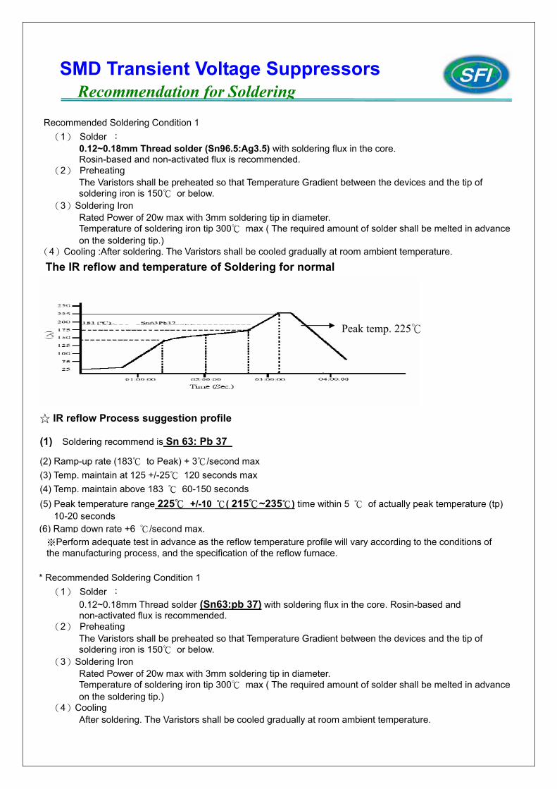
The IR reflow and temperature of Soldering for normal
☆ IR reflow Process suggestion profile
(1) Soldering recommend is Sn 63: Pb 37
(2) Ramp-up rate (183℃ to Peak) + 3℃/second max (3) Temp. maintain at 125 +/-25℃ 120 seconds max (4) Temp. maintain above 183 ℃ 60-150 seconds (5) Peak temperature range 225℃ +/-10 ℃( 215℃~235℃) time within 5 ℃ of actually peak temperature (tp)
10-20 seconds (6) Ramp down rate +6 ℃/second max.
* Recommended Soldering Condition 1 (1) Solder :
0.12~0.18mm Thread solder (Sn63:pb 37) with soldering flux in the core. Rosin-based and non-activated flux is recommended.
(2) Preheating The Varistors shall be preheated so that Temperature Gradient between the devices and the tip of soldering iron is 150℃ or below.
(3)Soldering Iron Rated Power of 20w max with 3mm soldering tip in diameter. Temperature of soldering iron tip 300℃ max ( The required amount of solder shall be melted in advance on the soldering tip.)
(4)Cooling After soldering. The Varistors shall be cooled gradually at room ambient temperature.
Peak temp. 225℃
※Perform adequate test in advance as the reflow temperature profile will vary according to the conditions of the manufacturing process, and the specification of the reflow furnace.
SMD Transient Voltage Suppressors Recommendation for Soldering
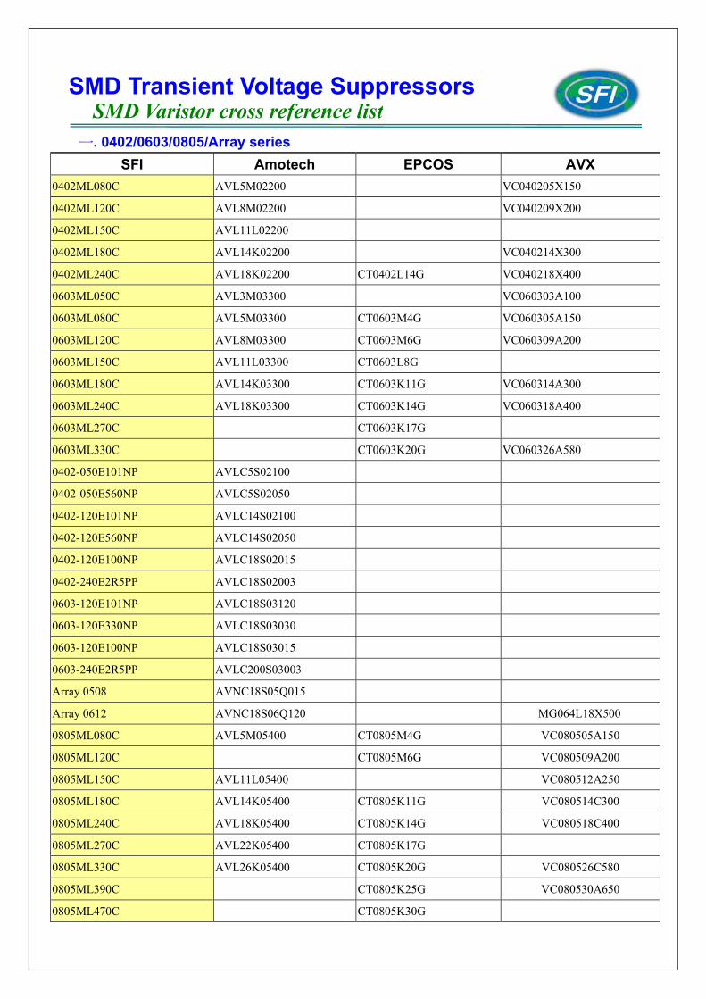
一. 0402/0603/0805/Array series SFI Amotech EPCOS AVX
0402ML080C AVL5M02200 VC040205X150
0402ML120C AVL8M02200 VC040209X200
0402ML150C AVL11L02200
0402ML180C AVL14K02200 VC040214X300
0402ML240C AVL18K02200 CT0402L14G VC040218X400
0603ML050C AVL3M03300 VC060303A100
0603ML080C AVL5M03300 CT0603M4G VC060305A150
0603ML120C AVL8M03300 CT0603M6G VC060309A200
0603ML150C AVL11L03300 CT0603L8G
0603ML180C AVL14K03300 CT0603K11G VC060314A300
0603ML240C AVL18K03300 CT0603K14G VC060318A400
0603ML270C CT0603K17G
0603ML330C CT0603K20G VC060326A580
0402-050E101NP AVLC5S02100
0402-050E560NP AVLC5S02050
0402-120E101NP AVLC14S02100
0402-120E560NP AVLC14S02050
0402-120E100NP AVLC18S02015
0402-240E2R5PP AVLC18S02003
0603-120E101NP AVLC18S03120
0603-120E330NP AVLC18S03030
0603-120E100NP AVLC18S03015
0603-240E2R5PP AVLC200S03003
Array 0508 AVNC18S05Q015
Array 0612 AVNC18S06Q120 MG064L18X500
0805ML080C AVL5M05400 CT0805M4G VC080505A150
0805ML120C CT0805M6G VC080509A200
0805ML150C AVL11L05400 VC080512A250
0805ML180C AVL14K05400 CT0805K11G VC080514C300
0805ML240C AVL18K05400 CT0805K14G VC080518C400
0805ML270C AVL22K05400 CT0805K17G
0805ML330C AVL26K05400 CT0805K20G VC080526C580
0805ML390C CT0805K25G VC080530A650
0805ML470C CT0805K30G
SMD Transient Voltage Suppressors SMD Varistor cross reference list
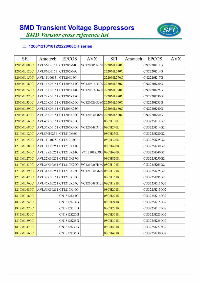
二. 1206/1210/1812/2220/08CH series
SFI Amotech EPCOS AVX SFI Amotech EPCOS AVX 1206ML080C AVL5M06151 CT1206M4G VC120605A150 2220ML180C CN2220K11G
1206ML120C AVL8M06151 CT1206M6G 2220ML240C CN2220K14G
1206ML150C AVL11L06151 CT1206L8G 2220ML270C CN2220K17G
1206ML180C AVL14K06151 CT1206K11G VC120614D300 2220ML330C CN2220K20G
1206ML240C AVL18K06151 CT1206K14G VC120618D400 2220ML390C CN2220K25G
1206ML270C AVL22K06151 CT1206K17G 2220ML470C CN2220K30G
1206ML330C AVL26K06151 CT1206K20G VC120626D580 2220ML560C CN2220K35G
1206ML390C AVL31K06151 CT1206K25G 2220ML680C CN2220K40G
1206ML470C AVL38K06151 CT1206K30G VC120630D650 2220ML820C CN2220K50G
1206ML560C AVL45K06151 CT1206K35G 08CH180L CU3225K11G2
1206ML680C AVL56K06151 CT1206K40G VC120648D101 08CH240L CU3225K14G2
1210ML120C AVL8M10251 CT1210M6G 08CH330L CU3225K20G2
1210ML150C AVL11L10251 CT1210L8G 08CH390K CU3225K25G2
1210ML180C AVL14K10251 CT1210K11G 08CH470K CU3225K30G2
1210ML240C AVL18K10251 CT1210K14G VC121018J390 08CH680K CU3225K40G2
1210ML270C AVL22K10251 CT1210K17G 08CH820K CU3225K50G2
1210ML330C AVL26K10251 CT1210K20G VC121026H560 08CH101K CU3225K65G2
1210ML390C AVL31K10251 CT1210K25G VC121030G620 08CH121K CU3225K75G2
1210ML470C AVL38K06151 CT1210K30G 08CH151K CU3225K95G2
1210ML560C AVL45K10251 CT1210K35G VC121048G101 08CH181K CU3225K115G2
1210ML680C AVL56K10251 CT1210K40G 08CH201K CU3225K130G2
1812ML180C CN1812L11G 08CH221K CU3225K140G2
1812ML240C CN1812K14G 08CH241K CU3225K150G2
1812ML270C CN1812K17G 08CH271K CU3225K175G2
1812ML330C CN1812K20G 08CH361K CU3225K230G2
1812ML390C CN1812K25G 08CH391K CU3225K250G2
1812ML470C CN1812K30G 08CH431K CU3225K275G2
1812ML560C CN1812K35G 08CH471K CU3225K300G2
SMD Transient Voltage Suppressors SMD Varistor cross reference list