Embed Size (px)
Citation preview

Restricted Access Barrier Systems & Isolators
Gordon Farquharson
July 2017

Slide 2 © PharmOut 2017
Learning objectives
We will Learn
• What isolators are and why they were developed
• The difference between a RABS and an isolator
• The fundamental types of isolators
• The basics of isolator design and how materials are aseptically transferred to the isolator interior
• How isolators are decontaminated

Slide 3 © PharmOut 2017
Cleanroom contamination
• People are the greatest source of bio-contamination in the manufacture of sterile products.
• Separation of the people from the aseptic zone is the best method for controlling contamination.
• Physical barrier segregation is the method of choice

Slide 4 © PharmOut 2017
Increasing system integrity
Increased sterility assurance
RABS
Isolators
The aseptic integrity spectrum”
Advanced aseptic processing

Slide 5 © PharmOut 2017
Characterising The Technologies
© PharmOut 20155

Slide 6 © PharmOut 2017
Traditional cleanroom – characteristics
• Grade B/ISO7 Room scale critical environment contains operators
• Critical Grade A/ISO5 Aseptic process Core located in the Grade B/ISO7 room
• Operators open equipment from surrounding Grade B/ISO7 room to load the process and intervene using defined SOPs. High reliance on operator garments
• Bio-decontamination…
‒ Topical disinfection of surfaces
‒ Room fumigation in some cases (rare these days)
• Separation between operators and aseptic process core
‒ Polycarbonate doors
‒ Screens
‒ Curtains

Slide 7 © PharmOut 2017
Conveyor
Vial
Nozzle
Filling
Mechanism
Conventional Clean Room
HEPA Filters
Class 100
(ISO 5)
Grade B
RoomGrade A
Zone
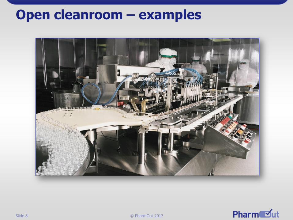
Traditional cleanroom – principles
Slide 8 © PharmOut 2017
Open cleanroom – examples

Slide 9 © PharmOut 2017
Open cleanroom – examples

Slide 10 © PharmOut 2017
Traditional cleanroom –is it acceptable today?
• The traditional open cleanroom practice of 30 years ago is now under great pressure – examples:
• Lack of sterilisation of stopper hoppers, bowl feeders and placers
• Requirement to achieve Grade A continuity in the handling of change parts and components such as stoppers – requirement to mimic the protection afforded by the isolator or RABS
• My personal opinion is that the “open Cleanroom” approach is no longer acceptable practice = NOT cGMP

Slide 11 © PharmOut 2017
The minimum acceptable practice today
• Rigid screens separate personnel from the aseptic process.
• Highly controlled access to the machine enclosure.

Slide 12 © PharmOut 2017
Conveyor
Vial
Nozzle
Filling
Mechanism
HEPA Filters
Class 100
(ISO 5)
3-6" From
HEPAS
Class 10,000
(ISO 7)
HVAC - Fans
Grade A
Zone
Grade B
Room
Minimum open cleanroom – principles (limited access)

Slide 13 © PharmOut 2017
The “RABS” restricted access barrier system

Slide 14 © PharmOut 2017
Definitions (ISPE)
• A barrier system is:
• “A system of physical partitions that affords Grade A protection by partially separating its interior from the surrounding environment utilizing airflow.”
• Restricted Access Barrier System (RABS) is:
• “An aseptic processing system that provides an enclosed, but not closed, environment meeting Grade A conditions utilizing a rigid-wall enclosure and air overspill to separate its interior from the surroundingenvironment.”
Slide 15 © PharmOut 2017
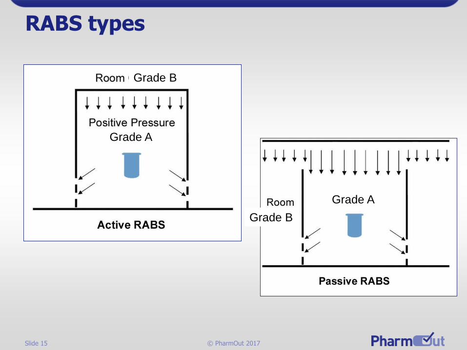
RABS types
Grade A
Grade A
Grade B
Grade B

Slide 16 © PharmOut 2017
RABS – characteristics
• The Grade B/ISO7 Room scale critical environment contains operators
• Critical Grade A/ISO5 Aseptic process Core sits in Grade B/ISO7 room
• Operators use glove ports for intervention, and closed component handling from the surrounding Grade B/ISO7 room
• Bio-decontamination…generally as open room
‒ Topical disinfection of surfaces
‒ Room fumigation in some cases (rare these days)
• Separation between operators and Grade A/ISO5 Aseptic process core
‒ Polycarbonate doors
‒ Screens
With glove ports and transfer
ports for components

Slide 17 © PharmOut 2017
Conveyor
Vial
Nozzle
Filling
Mechanism
HEPA Filters
Class 100
(ISO 5)
HVAC
Class
10,000
(ISO 7)
Grade B
Grade A
Locally increased
UDAF zone to protect door opening for very limited
interventions
Grade B
Room
Passive RABS
In passive RABS
resistance to airflow can
cause lateral flows.
RABS – principles

Slide 18 © PharmOut 2017
Conveyor
Vial
Nozzle
Filling
Mechanism
HEPA Filters
Class 100
(ISO 5)
HVAC
Class
10,000
(ISO 7)
Grade A
Locally increased UDAF zone to protect door opening
for very limited interventionsGrade B
Room
Active RABS
RABS – principles

Slide 19 © PharmOut 2017
RABS – examples

Slide 20 © PharmOut 2017
RABS – examples

Slide 21 © PharmOut 2017
The “closed RABS”“gassable RABS”restricted access barrier system

Slide 22 © PharmOut 2017
Conveyor
Vial
Nozzle
Filling
Mechanism
HEPA Filters
Class 100
(ISO 5)
HVAC
Class10,000(ISO 7)
Grade BGrade A
This variation has the ability to close a valve to allow a closed system gassing, fumigation or bio-decontamination or surface sterilisation.
HEPA Filters
HVAC
HEPA Filters
HVAC
Closed RABS – principles

Slide 23 © PharmOut 2017
Conveyor
Vial
Nozzle
Filling
Mechanism
HEPA Filters
Class 100
(ISO 5)
HVAC
Class
10,000
(ISO 7)
Grade B Grade A
Closed RABS – principles
This variation has the ability to close a valve to allow a closed system gassing, fumigation or bio-decontamination or surface sterilisation.

Slide 24 © PharmOut 2017
The “Isolator”

Slide 25 © PharmOut 2017
US FDA’s view of (aseptic processing) isolators
• A well-designed positive pressure isolator, supported by adequate procedures for its maintenance, monitoring, and control, offers tangible advantages over traditional aseptic processing, including fewer opportunities for microbial contamination during processing.

Slide 26 © PharmOut 2017
Definitions (ISPE)
• An (aseptic) isolator is defined as
• “A decontaminated unit meeting Grade A conditions that provides uncompromised, continuous, isolation of its interior from the surrounding environment.”

Slide 27 © PharmOut 2017
Isolator – characteristics
• Small contained enclosure excludes process operators
• Critical Grade A Aseptic process Core sits in Grade C or D “at rest” room
• Operators only open equipment when off-line. Human access via glove ports, and closed process loading
• Bio-decontamination…
• Topical disinfection of surfaces inside isolator
• or more often …… Internal Isolator aerosol or vapour sanitisation
• Separation between operators and aseptic process core
• Isolator shell
• Windows
• Glove ports
• Transfer ports sterilised change-parts & components

Slide 28 © PharmOut 2017
Conveyor
Vial
Nozzle
Filling
Mechanism
Isolator
HEPA Filters
Class 100
(ISO 5)
AirReturn
Class
100,000
(ISO 8)
Isolator – principles
Grade A
Grade C
or min Grade D

Slide 29 © PharmOut 2017
Isolator – examples

Slide 30 © PharmOut 2017
Isolator – examples

Slide 31 © PharmOut 2017
Photo Courtesy of Bosch Packaging –www.boschpackaging.com
1989 – ampoule filling isolator with softwall isolator

Slide 32 © PharmOut 2017
www.pharmsystems.com/ LabServices/LabFacility_...Half suit (SS/polycarbonate isolator)

Slide 33 © PharmOut 2017
Isolator transfer operations
• The mechanisms chosen for the various transfer operations are crucial to protect the aseptic processing core.
• A direct interface with the autoclave, de-pyrogenation tunnel, and/or sterilizing transfer device, is the most secure approach.
• The transfer mechanism should be capable of protecting the interior from bio-contamination. The major consideration is the ability to sterilize or surface bio-decontaminate the contents of the transfer device before allowing access to the controlled workspace.

Slide 34 © PharmOut 2017
Isolator “rapid transfer ports”
• A common technique for passing items into the enclosure is via a rapid transfer port (RTP).
• In this case, items are sterilized in a canister which is designed to be docked onto the transfer door of the enclosure without transferring contamination from outside to inside.
• The docking process seals the outer face of the transfer door to the lid of the canister in an air tight manner. Air tightness is ensured by the use of multiple-lip seal gaskets.

Slide 35 © PharmOut 2017
Rapid transfer ports
Courtesy Central Research Laboratories - www.skan.ch/Rtp.pdf

Slide 38 © PharmOut 2017
Isolator technology –some other important considerations
• Glove Systems and Gauntlets
• Leak Detection
• Bio-decontamination method
• Airflow Modeling
• Vapour and Material Compatibility
• Environmental Monitoring

Slide 39 © PharmOut 2017
Gloves – the weak point ?
• Monitoring should be carried out routinely and should include frequent leak testing of the isolator and glove/sleeve system. EU Annex 1
• The integrity of gloves, half-suits, and seams should receive daily attention and be addressed by a comprehensive preventative maintenance program. FDA Aseptic guide

Slide 40 © PharmOut 2017
Isolator glove leak tests
• Methods
• Pressure decay test (most common)
• Oxygen diffusion test
• Frequency
• Before batch or campaign

Slide 41 © PharmOut 2017
Enclosure leak test methods
• Quantified
• Pressure decay test
• Leakage rate test – Maintaining a constant pressure with a known flow rate
• Detective work – finding leaks
• Tracer gas
• Smoke
• Ultrasonics

Slide 42 © PharmOut 2017
Isolator bio-decontamination
• Cleaning of enclosure should be carried out before decontamination
• It should be noted that only surface bio-decontamination is accomplished by the various treatments that may be used.
• Surfaces must be exposed sufficiently to the agent in order to achieve isolator bio-decontamination.

Slide 43 © PharmOut 2017
Frequency of bio-decontamination
• The design of the interior and content of an isolator should allow for its frequent decontamination.
• When an isolator is used for multiple days between decontamination cycles, the frequency adopted should be justified. (ultimately validated by process media simulations)
• This frequency, established during validation studies, should be re-evaluated and increased if production data indicate deterioration of the microbiological quality of the isolator environment.

Slide 44 © PharmOut 2017
Decontamination cycles
• Cycles should be developed with an appropriate margin of over-kill to provide confidence in robustness of the decontamination processes.
• Normally, a four- to six-log reduction can be justified depending on the application.
• The specific BI spore concentration and resistance used and the selection of BI placement sites should be justified.
• The uniform distribution of a defined concentration of decontaminating agent should also be evaluated as part of these studies.

Slide 45 © PharmOut 2017
How are isolators bio-decontaminated?
• Most common bio-decontamination agent is vaporized hydrogen peroxide used as a vapour-in-air mixture although other materials are available. Recently aerosolized H2O2 has been introduced.
• Operation must be conducted at controlled temperature and relative humidity (~30%)
• Catalytic converters to remove breakdown products of hydrogen peroxide at the end of a bio-decontamination cycle with H2O2

Slide 46 © PharmOut 2017
Typical vapour H2O2 cycle*
• Dehumidification – Reduction of relative humidity
• Condition – Rapid increase to desired hydrogen peroxide vapor concentration
• Biodecontamination – Maintenance of desired hydrogen peroxide vapor concentration
• Aeration – Rapid reduction of hydrogen peroxide vapor
*Cycle used by STERIS VHP® M1000 Modular Continuous
Biodecontamination System – www.steris.com

Slide 47 © PharmOut 2017
Typical bio-decontamination cycle
STERIS VHP® M1000 Modular Continuous
Biodecontamination System – www.steris.com

Slide 48 © PharmOut 2017
Environmental monitoring
• The expectation is to follow cleanroom practice as defined in the GMPs.
• The greatest challenge is the transfer of microbiological media INTO and OUT of the isolator during processing.
• The micro monitoring ensures acceptable microbiological quality of:
• Air
• Surfaces
• Gloves (or half-suits)
• Airborne particle monitoring is required to evaluate particle levels within the isolator during processing.

Slide 49 © PharmOut 2017
Summary
Learned
• What isolators are and why they were developed
• What distinguishes a RABS from an isolator
• The fundamental types of isolators
• The basics of isolator design and how materials are aseptically transferred to the isolator interior
• How isolator surfaces are decontaminated
• Environmental monitoring follows cleanroom practice

Slide 50 © PharmOut 2017
Thank you for your time.Questions?
Gordon Farquharson
www.pharmout.net
Executive Consultant